1. Introduction
When an aircraft flies in icing weather conditions, ice forms on windward surfaces because of the freezing of supercooled water droplets. Ice accumulation on the wings of an aircraft can negatively impact its lift and manoeuvrability, increasing the risk of accidents and impacting flight performance. In severe cases, this can create safety hazards [
1]; therefore, airworthiness standards require must be configured with a corresponding anti-icing system to the wings. Aerothermal anti-icing technology transfers hot engine air to the wing surface through the compressor's pilot line. Compared with traditional aerothermal anti-icing technology, electric anti-icing systems have the advantages of a fast response time, simple system design, flexible heating mode, and good compatibility with composite materials [
2]. With the gradual increase in the use of composite materials in the main load-bearing structures of civil airliners [
3], electrothermal anti-/de-icing technology has become one of the most promising anti-/de-icing technologies.
Owing to the anisotropic arrangement of the reinforcement material, the mechanical and thermomechanical properties of composite structures are characterized by significant anisotropy. Composite structures with electrically heated anti-icing systems are typically composed of multiple layers, including an insulation layer, a heating layer, and a bonding layer. This multilayer configuration further increases the complexity of the mechanical and thermal properties of the composite structure. Composite structures are susceptible to external impacts and other effects during service, which can cause delamination damage within laminated structures [
4,
5,
6,
7]. On the one hand, the multilayer structure formed after the addition of the electrothermal anti-icing system greatly increases the probability of delamination damage and is likely to lead to the emergence of interlayer delamination cracks, and the high temperature of electrothermal heating is prone to causing delamination because of the concentration of temperature and thermal stress [
8]. On the other hand, delamination damage can lead to an uneven temperature distribution during electric heating, which affects the anti-icing efficiency. Therefore, the ability of composite electrothermal systems containing delamination damage in terms of the temperature field and mechanics needs to be studied urgently.
In most cases, delamination damage in composite materials is difficult to detect in time via conventional inspection methods, and composite components on aircrafts often continue to operate in a damaged state. This unrepaired damage can significantly affect the mechanical and thermal properties of the material, which in turn poses a potential threat to flight safety. Polla, A [
9] et al. investigated the effect of heat on the mechanical properties of Carbon Fiber Reinforced Plastic(CFRPs) and reported that composites containing cracks are affected by temperature and that the absolute strength threshold of the matrix decreases as the temperature approaches the glass transition temperature, which affects the properties of the composite. Tay et al. [
10] studied the mechanical properties of composites containing preset delamination and reported that residual thermal stresses have a greater effect on delamination near the surface of the composite. Furthermore, another study reported that composite laminates with preset damage exhibit approximately 14% lower bending strength than undamaged laminates, and experience higher surface temperatures under electric heating conditions[
11]. There is an interaction between delamination damage and temperature distribution; thus, numerical calculations of the thermal multiphysics fields are necessary to study the electrothermal anti-icing structure of a wing subjected to delamination damage.
Numerical calculation is an important method for studying changes in material and structural properties in multiple physical fields and is widely used by scholars in calculations for wing anti-/de-icing systems[
12,
13,
14]. Shen et al. [
15] established a thermal conductivity equation for anisotropic composites, conducted numerical simulations on wings to investigate the impact of anisotropy on electrothermal anti-icing systems, and obtained the temperature of the anti-icing surface. Lou et al. [
16] used a uniform heat flux boundary to heat the leading edge of the inner skin of a wing and calculated the thermal load on the wing skin on the basis of external flow fields and droplet impact; by performing coupled heat transfer calculations between the inner and outer skins, they obtained the temperature field on the de-icing surface. However, none of these methods can accurately simulate multiple delamination events and matrix crack damage in composite structures at the same time. The thermally extended layer-by-layer/3D solid element method used in this work not only simulates the composite material layer-by-layer but also accurately analyses the displacement and stress fields at the delamination leading edges and crack tips, and the two methods can be combined to improve the convergence speed by optimizing the algorithm and increasing the accuracy of the calculation.
In summary, delamination damage in composite materials prevents the structure from achieving its designed stiffness and strength during service. When combined with a multilayered anti-icing system, this will significantly increase the complexity and severity of the issue and put forward higher requirements for theoretical calculations and experimental implementation, which may be the main reason for the lack of relevant research at present. Therefore, this work integrates the study of delamination damage in composite materials with electrothermal anti-icing systems. It utilizes the thermally extended layer-by-layer/3D solid element method to explore the complex interactions between two features. More importantly, considering that delamination is more likely to occur in multilayered anti-icing and de-icing systems, this project conducts thermomechanical multiphysics numerical simulations to study the electrothermal anti-icing structure of composite wing leading edges with delamination damage. This investigation explores the impact of delamination damage at different locations on the temperature field, thermal stress, and displacement due to thermal deformation of the electrothermal anti-icing structure. These findings provide theoretical support for the application of electrothermal anti-icing systems in composite materials.
2. Composite Wing Leading Edge Modelling and Anti-Icing Environment Settings
2.1. Composite Wing Leading Edge Modelling
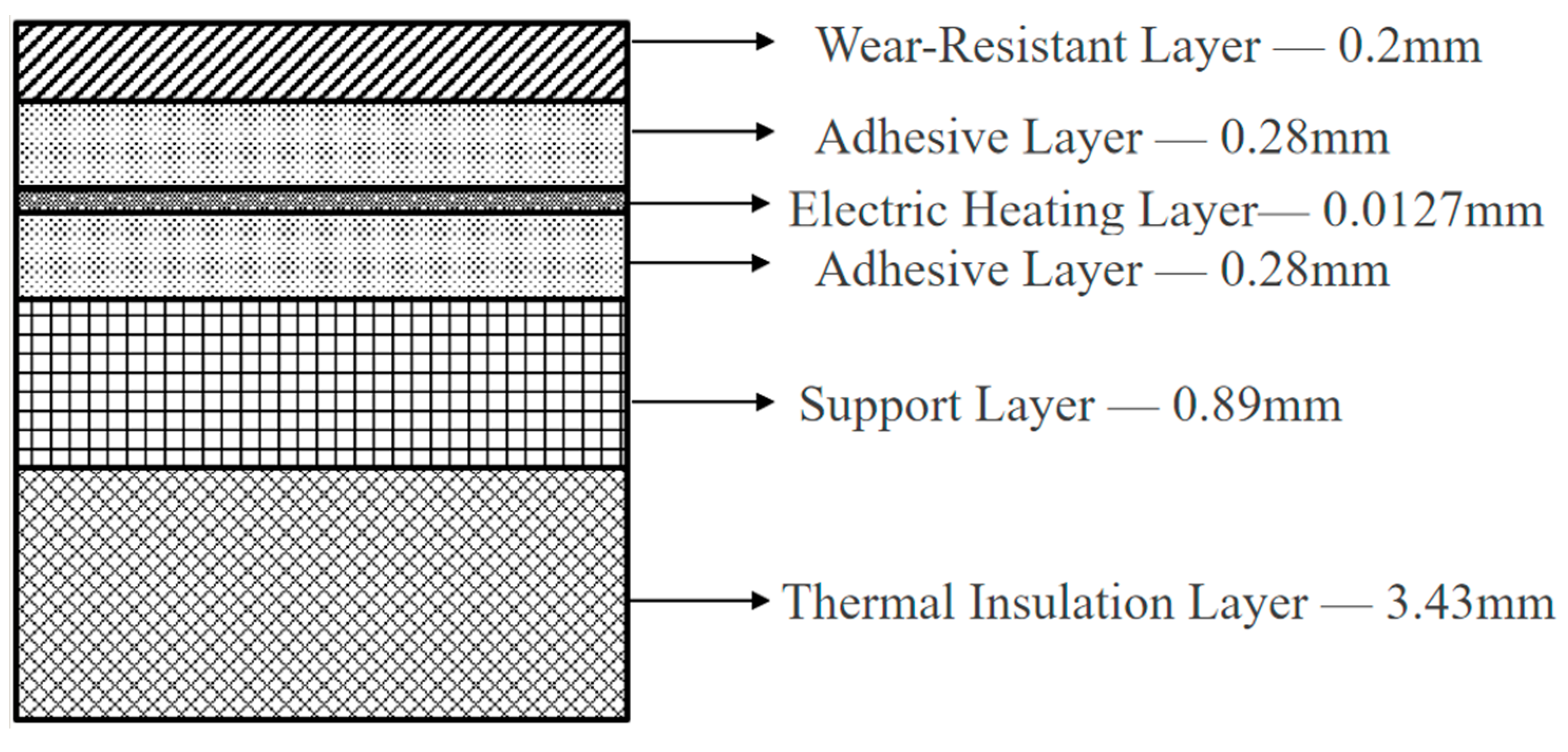
In this study, the model of the electric heating de-icing system referenced is based on experiments conducted by NASA [
17]. This de-icing model employs a multilayered material structure, which consists of, from the top to the bottom, a wear-resistant layer (carbon fibre composite) with a thickness of 0.2 mm, followed by an adhesive layer (H77 adhesive) that is 0.28 mm thick, an electric heating layer (nickel‒chromium alloy) measuring 0.0127 mm, another adhesive layer measuring 0.28 mm, a support layer (glass fibre composite) with a thickness of 0.89 mm, and a thermal insulation layer (silicone foam) with a thickness of 3.43 mm. The physical parameters of each layer of material are shown in
Table 1. Considering that the support layer material is anisotropic, it has different thermal conductivities, moduli of elasticity, coefficients of thermal expansion, and Poisson's ratios in the three directions, whereas the wear-resistant layer, adhesive layer, electric heating layer, and thermal insulation layer are isotropic and therefore have the same electrical conductivity in the three directions.
Figure 1
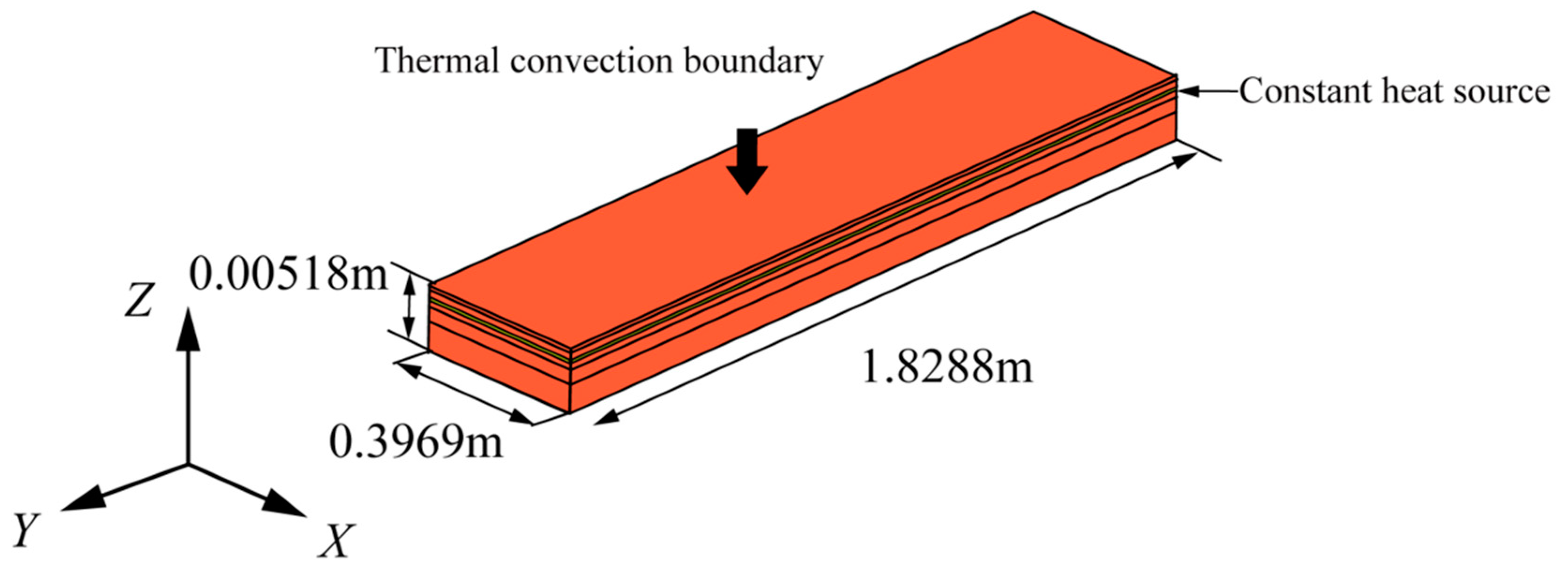
Heating units are generally distributed in a regular pattern on wings. A multilayer thermal conduction structure model of a flat plate is set up with reference to the wing configuration, incorporating seven heating units labelled A, B, C, D, E, F, and G, as shown in
Figure 2. The length of the flat plate is set to 1.8288 m and is designated the Y direction, whereas its width is 0.3937 m and is designated the X direction. The direction perpendicular to the plate is designated the Z direction. Heating units are placed in the central area of the model, with a length of 0.9144 m in the Y direction and a width of 0.19685 m in the X direction. The widths and heating powers for different zones are detailed in
Table 2.
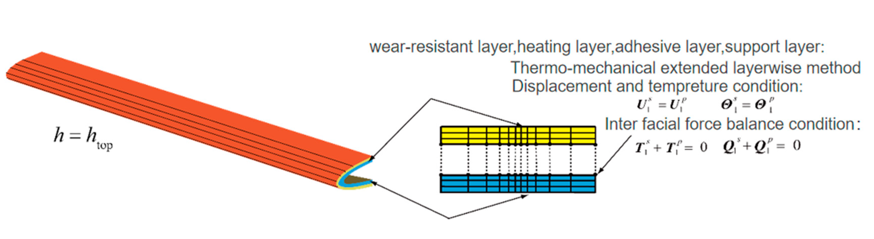
This paper uses the expansion layer-by-layer/3D solid element method [
18,
19,
20,
21,
22,
23,
24,
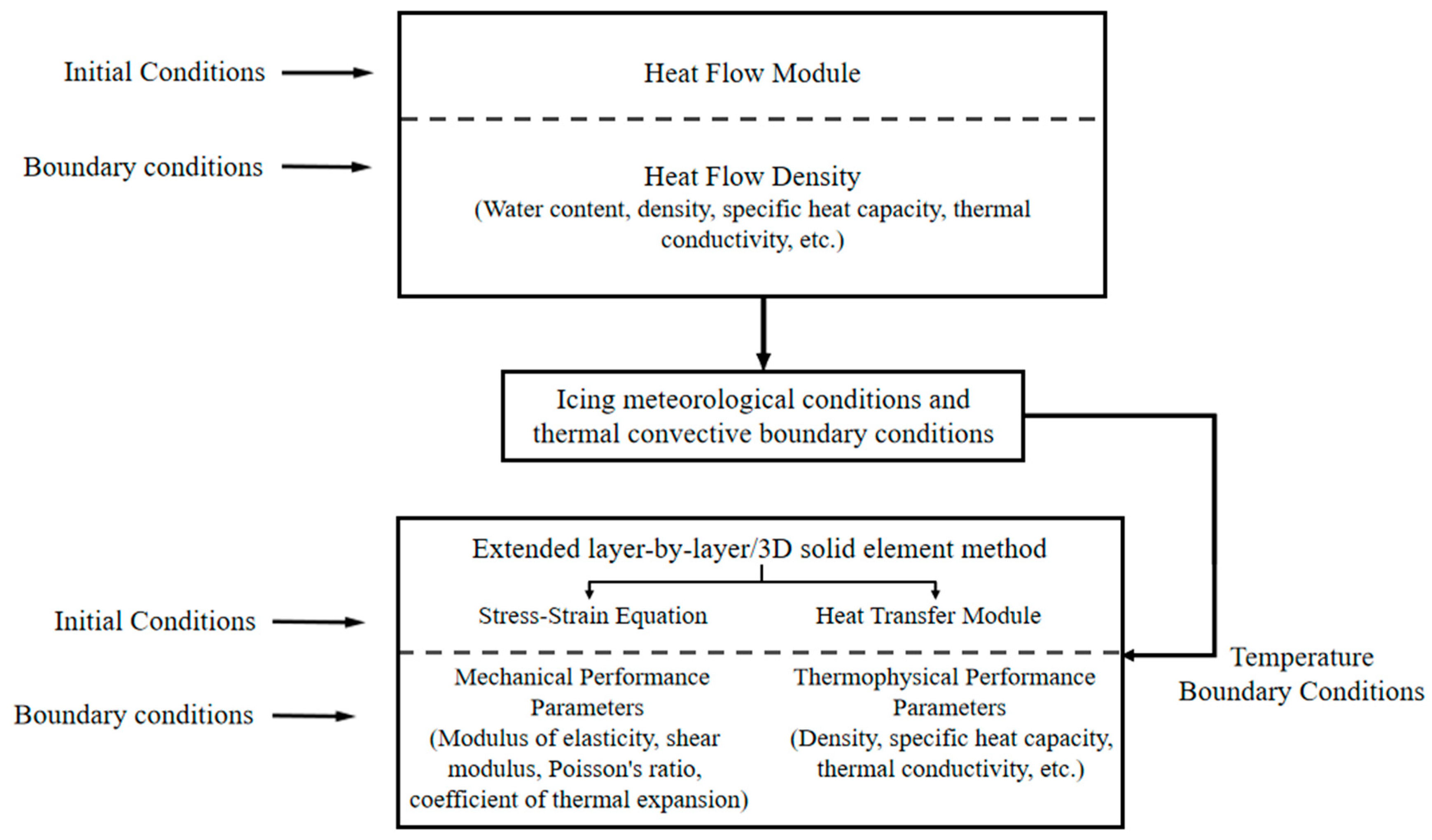
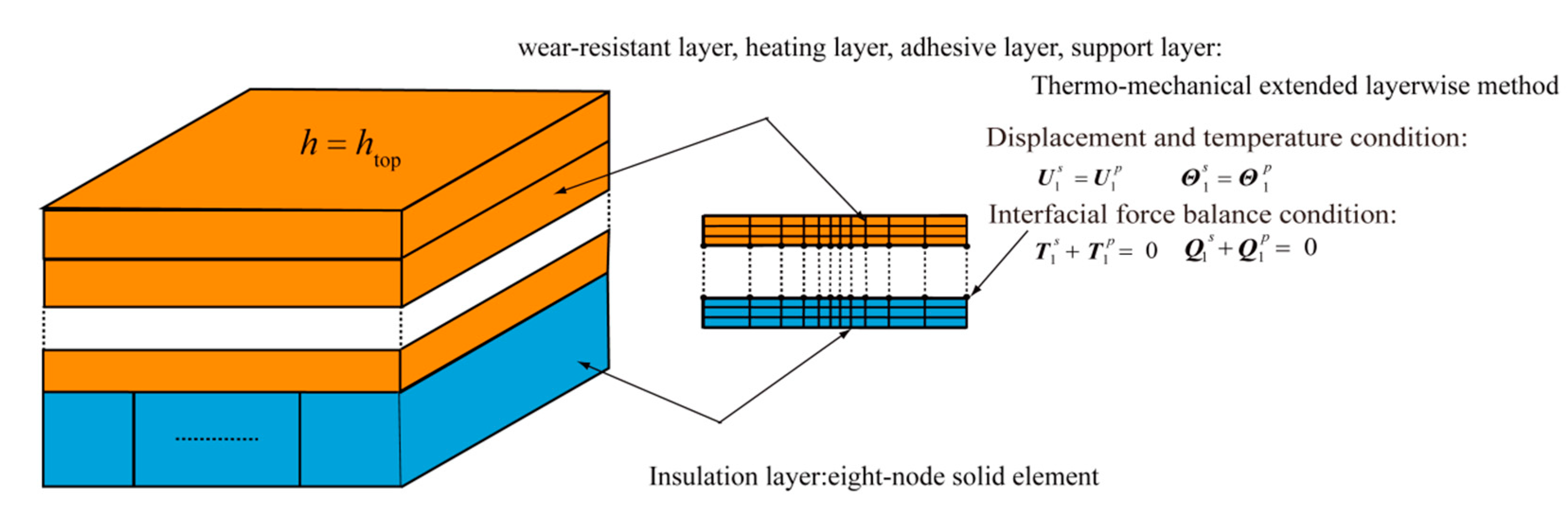
25] to investigate the electrothermal de-icing process of composite laminated panels. The upper part of the thermal insulation layer, which is prone to delamination damage, is investigated by the thermal expansion layer-by-layer method, and the thermal insulation layer, which is not prone to delamination damage, is investigated by the eight-node 3D solid element method for simulation. The equilibrium and coordination conditions between the thermal expansion layer-by-layer method and the eight-node 3D solid element method are based on compatibility conditions for temperature, displacement, and internal force balance. Finally, on the basis of the thermally extended layer-by-layer/3D solid element, the heat source and thermal convection boundary conditions are loaded into the model in the form of thermal loads, resulting in a thermodynamic model capable of simulating the electrothermal anti-icing process when applied to damaged composite laminates. The specific implementation process is shown in
Figure 4.
The mechanical properties of the materials in each layer are shown in
Table 3 and
Table 4. The mechanical properties of the OCV-LTX1240 glass fibre unidirectional tape with known anisotropic parameters were chosen to represent the support layer, i.e., the glass fibre resin layer.
Figure 5 illustrates the coordinate system, geometric dimensions, and boundary conditions. To simulate the electric heating structure fixed to the wing by rivets,the displacement boundary condition surrounding the structure is established as fully fixed constraints during the analysis process.
2.2. Composite Material Anti-Icing Environment and Delamination Damage Setting
The meteorological conditions for aircraft icing used for the calculations in this paper are those of Case 67A [
26], as shown in
Table 5. The droplet collection coefficients and convective environment coefficients are taken from the experimental values.
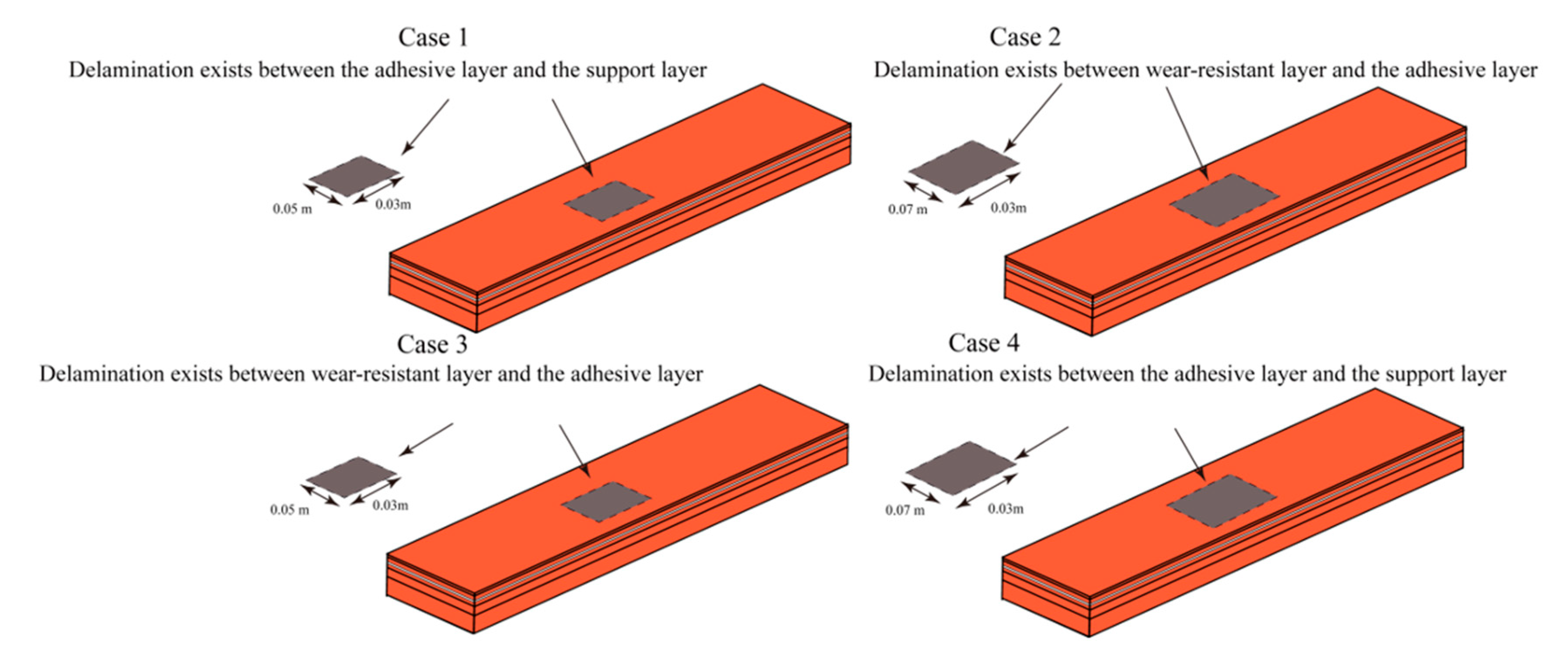
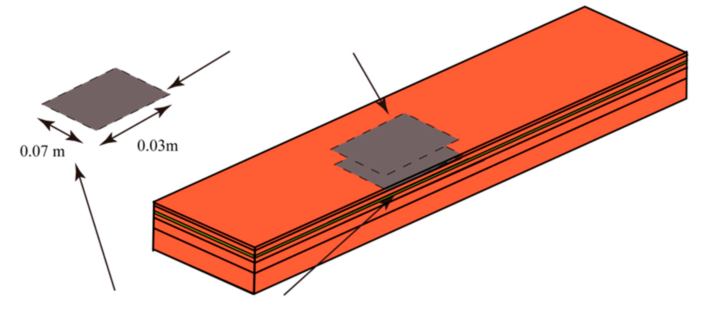
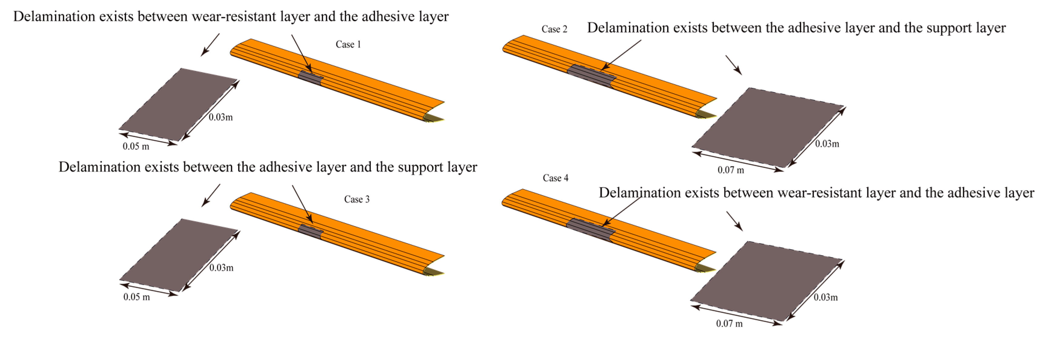
To compare the effects of the location of delamination damage and the size of the delamination damage region on the anti-icing performance of the electrically heated structure, calculations were carried out in this work for four cases, including two delamination damage locations and two delamination damage areas, as shown in
Figure 6.
2.3. Validation of Calculation Methods
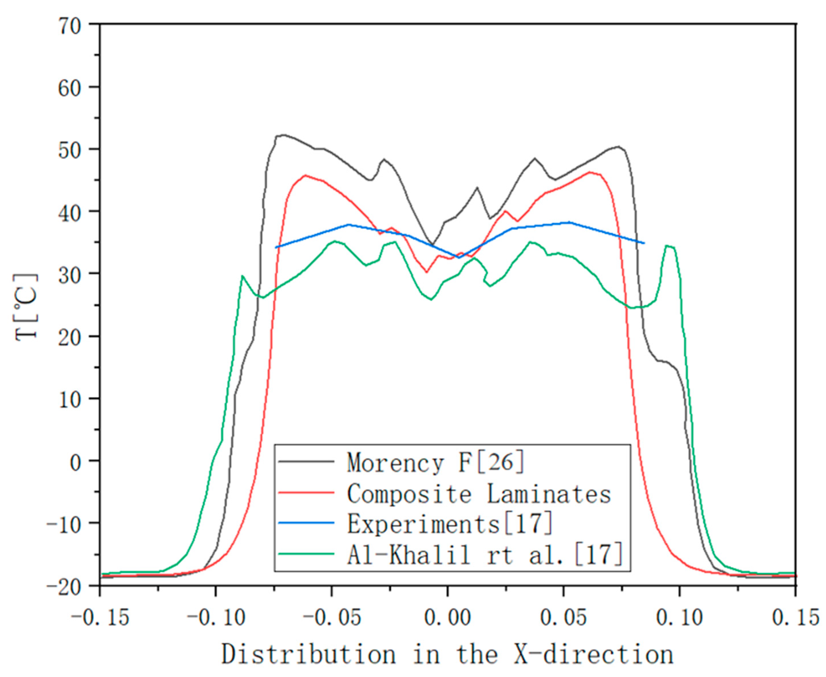
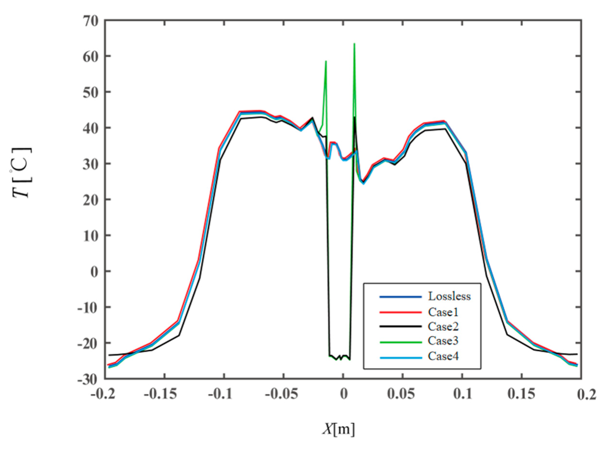
Al-Khalil, Morency [
17,
26], and others have investigated the electrothermal anti-icing process for wings when the meteorological conditions are those of Case 67A using experimental and computational methods and have provided experimental and simulation results for water collection coefficients, overflow water distributions, and temperature distributions of the anti-icing surfaces. Therefore, this calculation condition is also chosen for use in this paper, as shown in
Figure 7. The surface temperature distribution obtained by numerical simulation is very close to the change trend reported in the literature, and the simulation results and experiments are similar, which verifies the feasibility of the model and calculation method.
3. Finite Element Equations for Thermally Extended Layer-by-Layer/3D Solid Elements
The thermally extended layer-by-layer/3D solid element method was used to simulate the electrically heated anti-icing process for composite laminates [
18]. A brief description of the method is given in this section.
3.1. Heat Mixed Variational Theorem
The heat mixing variational theorem is used as a starting point for the theoretical derivation [
27]. The heat mixing variational principle is given by the following equation:
where σαβ, εαβ, uα, and eα represent the stress tensor, strain tensor, displacement vector, and temperature gradient vector, respectively;
,
, and
represent the entropy density, constant positive reference temperature, and density, respectively;
represents the temperature change relative to the reference temperature
; fα and Fα represent the body force and surface force on the boundary
; s represents the internal heat source; hα represents the heat flux vector; and
represents the heat flux on the boundary.
The force and thermal boundary conditions can be written as follows:
where
is the unit normal vector of the boundary.
The gradient relationship between the strain field and the thermal field is given by the following equation:
The constitutive equation is given by the following equation:
where
is the matrix of elastic stiffness constants,
is the stress temperature matrix,
is the coefficient of thermal expansion, and
is the coefficient of thermal conductivity.
3.2. Finite Element Equation for Thermally Extended Layer-by-Layer/3D Solid Elements
The part above the thermal insulation layer is simulated using the thermal expansion layer-by-layer method. For a detailed description of the thermal expansion layer-by-layer method, please refer to [
23]. The finite element equation utilized in this method is as follows:
In the equation,
;
;
;
; and
. M, K, and C are the mass, stiffness, and damping matrices, respectively; see the
Appendix A for specific expressions.
and
are mechanical and temperature load vectors, respectively, which can be expressed as follows:
where ht is the heat flux from the upper surface of the composite material.
Eight-node 3D solid elements are used to model the thermal insulation layer with the following finite element formula for the 3D thermally coupled problem:
The total finite element control equations are assembled via the dynamic thermal method proposed by Li [
28] et al. All the degrees of freedom (displacements and temperatures) in the control equations for the portion above the thermal insulation layer are divided into two groups: (1) the degrees of freedom that contact the thermal insulation layer (external degrees of freedom) and (2) the other degrees of freedom that do not contact the thermal insulation layer (internal degrees of freedom). Therefore, equations (3−5) can be transformed as follows:
where the superscript p refers to the extended layer-by-layer method. The subscript 1 indicates the degrees of freedom and loads (external degrees of freedom) that are at the interface between the extended layer-by-layer method and the 3D solid element method. Subscript 2 indicates degrees of freedom and loads that are not at the interface between the extended layer-by-layer method and the 3D solid element method (internal degrees of freedom). M, K, and C are the mass, stiffness, and damping of the thermomechanical extended layerwise method (TELM), all of which are given in specific form in the Appendix. The control equation (3−8) for the 3D solid element method can be similarly rewritten as follows:
where the superscript s refers to a 3D solid element. M, K, and C are the mass, stiffness, and damping of the 3D solid element, the specific forms of which are also given in the
Appendix A.
The displacement conditions, temperature conditions, and interface force balance conditions between the extended layer-by-layer and 3D solid element interface are simplified; the insulation layer and the support layer are considered rigidly connected, and their specific expressions are shown in equations (3-11).
A schematic of the method is shown in
Figure 8:
We can assemble the final control equation by using the compatibility conditional equation (3-11), which is given by the following equation:
4. Temperature Distribution of Composites with Multiple Delamination Damage Events
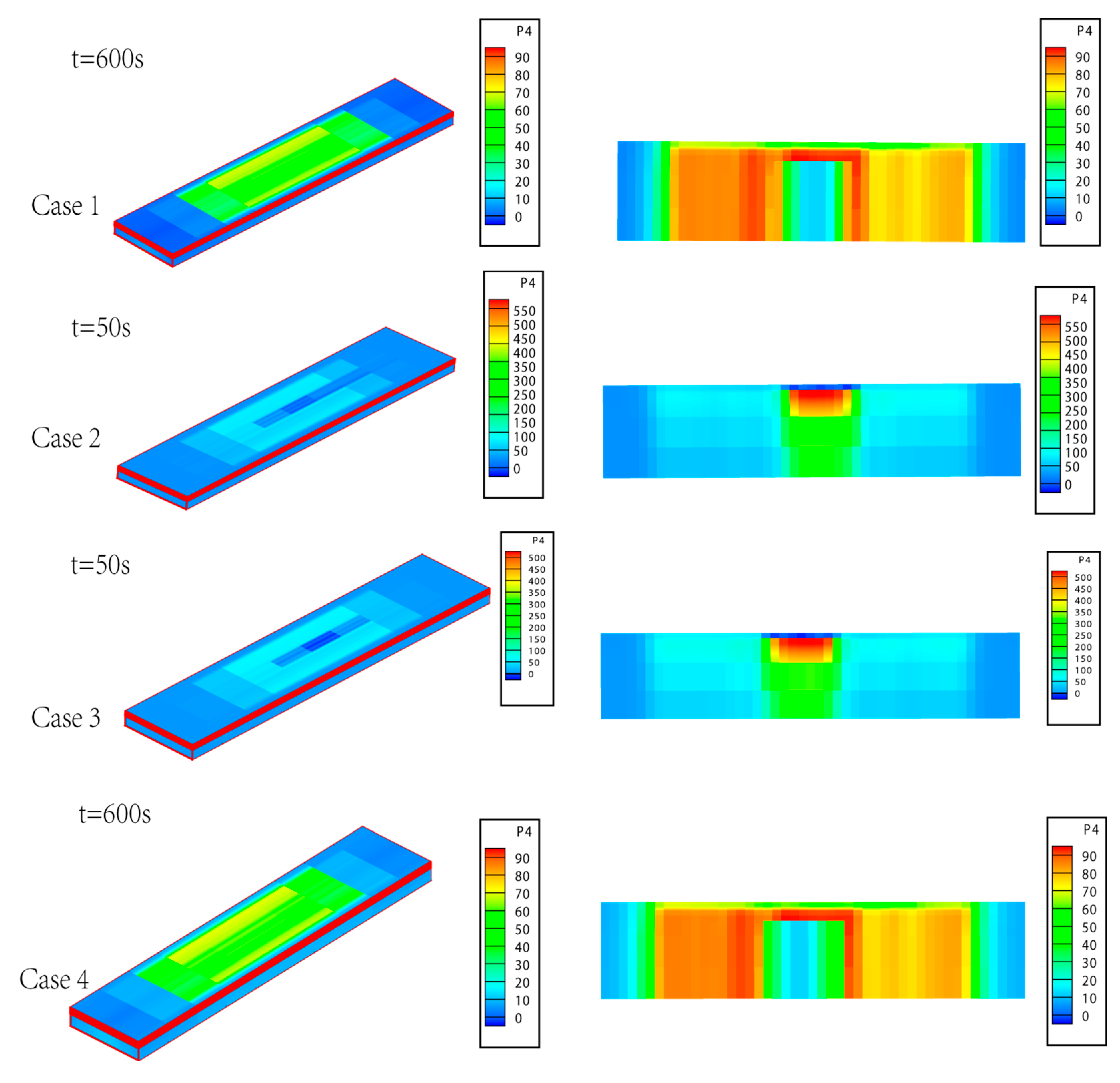
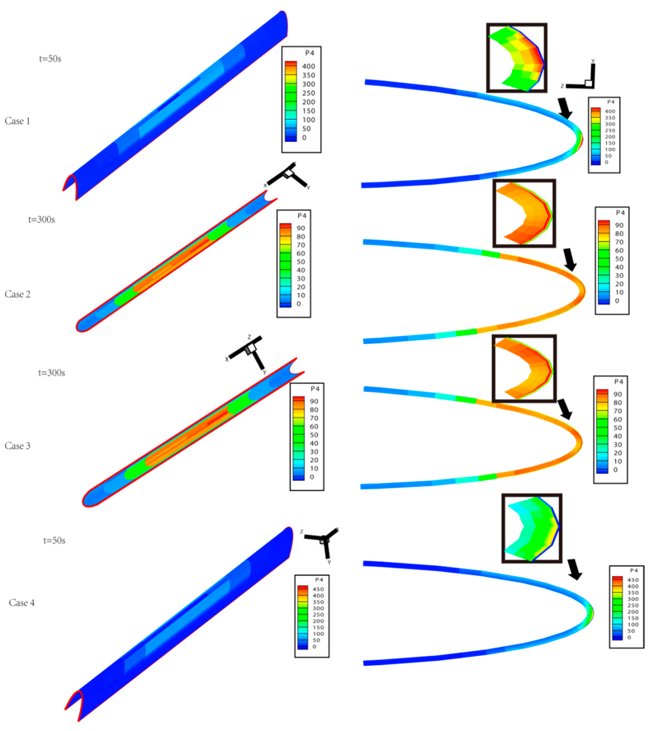
Figure 9 presents the temperature distributions of the composite laminate electric heating structures under different delamination conditions. The analysis indicates that when delamination occurs between the support layer and the adhesive layer (i.e., Case 1 and Case 4), temperature transfer cannot occur along the thickness direction, and the temperature distribution in the thickness direction is uneven, ultimately resulting in a nonuniform thermal stress distribution, which adversely affects structural integrity and safety.
Similarly, when delamination occurs between the wear-resistant layer and the adhesive layer (i.e., Case 2 and Case 3), the maximum temperature reaches approximately 500 °C at t = 50 s. This is because the influence of delamination damage causes the structure in the delaminated area to behave as a thermal conduction model with a high-power heat source but without convective heat transfer, leading to a sharp increase in temperature, which is unacceptable in engineering applications. The operational temperature range for the polyimide resin, the matrix material most commonly used in aircraft composite structures, is between 288 °C and 316 °C [
29], at which point the member is already in a state of failure; therefore, no further calculations are carried out for the later time steps.
Furthermore, a comparison of Case 2 and Case 3 reveals that with the expansion of the delamination area, the maximum temperature increases from 500 °C (Case 3) to 550 °C (Case 2), and the low-temperature region on the outer surface further expands. This phenomenon occurs because the expansion of the delaminated area obstructs temperature transfer along the thickness, further impeding the diffusion of heat from the heating zone. Consequently, the larger the delamination area is, the higher the maximum temperature and the lower the average temperature of the anti-icing surface, which ultimately leads to premature failure of the component and low anti-icing efficiency.
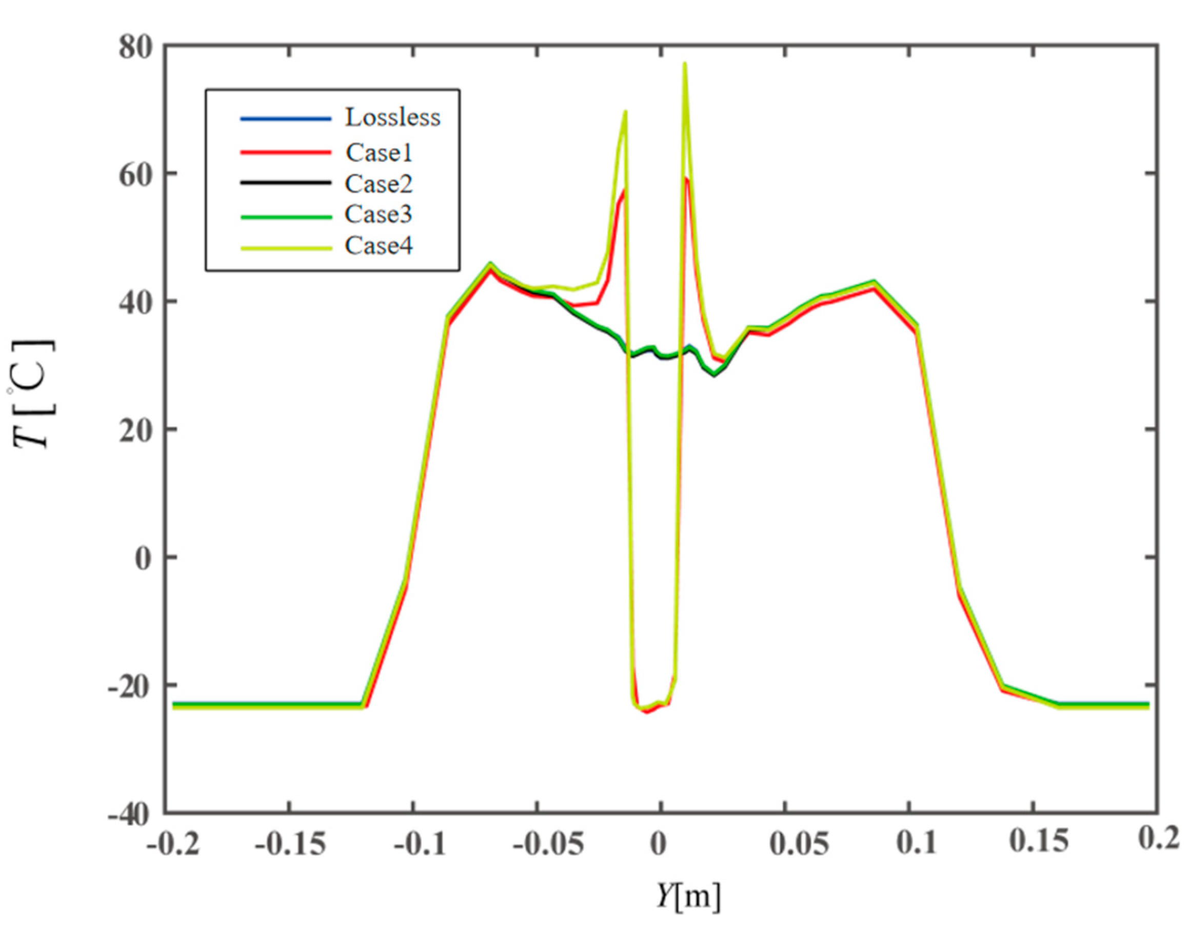
Figure 10 shows the temperature distribution on the anti-icing surface under different delamination conditions when t = 300 s and Y = 0.9144 m. A comparison of Case 1 and Case 3 indicates that, with the same delamination area, different locations of delamination lead to different anti-icing efficiencies for the anti-icing surface of the electrically heated composite material structure. Moreover, a comparison of Case 2 and Case 3 reveals that when the delamination region is between the electric heating layer and the anti-icing surface, the impact of delamination significantly affects the anti-icing efficiency. Notably, a marked increase in temperature is observed in front of and behind the low-temperature area of the anti-icing surface, which is due to the impact of delamination damage, leading to a sharp increase in the temperature of the delamination area below the surface and an increase in the temperature of the anti-icing surface around the delamination area.
A comparison of the results with those of the undamaged case reveals that for Case 1 and Case 4, when delamination damage occurs below the electric heating layer, the delamination area does not affect the temperature distribution on the anti-icing surface, and the temperature distribution curves almost overlap. This phenomenon occurs because delamination does not affect the upwards transfer of heat in this configuration; therefore, the heating effect of the electrically heated area on the surface is not affected.
To react to realistic situations with multiple delamination damage events, the multiple delamination damage events shown in
Figure 11 are selected for this study, and the anti-icing performance and the thermal performance are compared with those of the undamaged case.
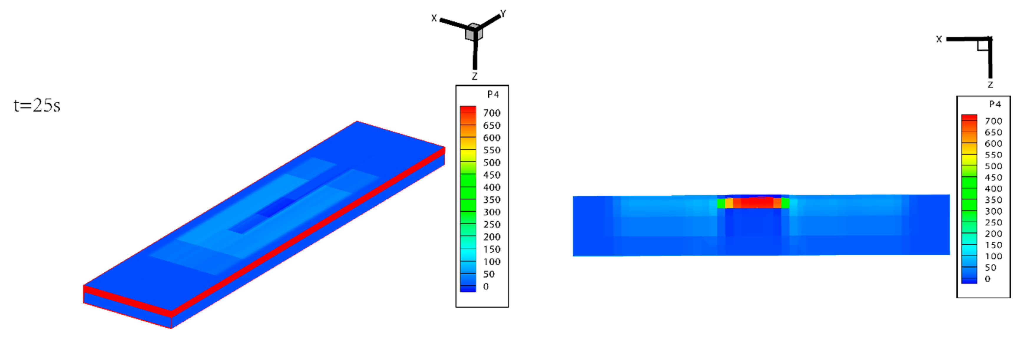
Figure 12 presents cloud diagrams of the temperature distribution in the composite laminate electric heating structure with multiple instances of delamination damage.
Because delamination damage occurs both above and below the electrically heated layer at the same time, the upwards and downwards transfer of temperature is obstructed. Consequently, the structure exhibits characteristics of both Case 2 and Case 4, with low-temperature regions on the anti-icing surface, a steep increase in temperature in the local area, and the lower part of the delamination area is almost not heated. As shown in
Figure 12, the maximum temperature of the structure reaches 700 °C at t = 25 s. Compared with that shown in
Figure 10, the maximum temperature in the case of multiple damage events is much greater than that in the case of a single damage event. This phenomenon arises because the damage interrupts the thermal transfer pathways in both directions. Moreover, the regions between the two delamination damage zones consist of an electric heating layer and an adhesive layer, where the electric heating layer is relatively thin and the thermal conductivity of the adhesive layer is very low. This configuration results in the blockage of heat transfer and causes severe local heating.
5. Surface Temperature and Thermal Stress Distribution of Airfoils with Preset Damage
In this paper, on the basis of Li [
28] et al., the existing thermal expansion layer-by-layer/3D solid element method is applied to study the electrically heated anti-icing process of a wing with an NACA0012 airfoil. The effects of delamination damage on the anti-icing performance and thermal deformation of a wing's electroheating structure are analysed.
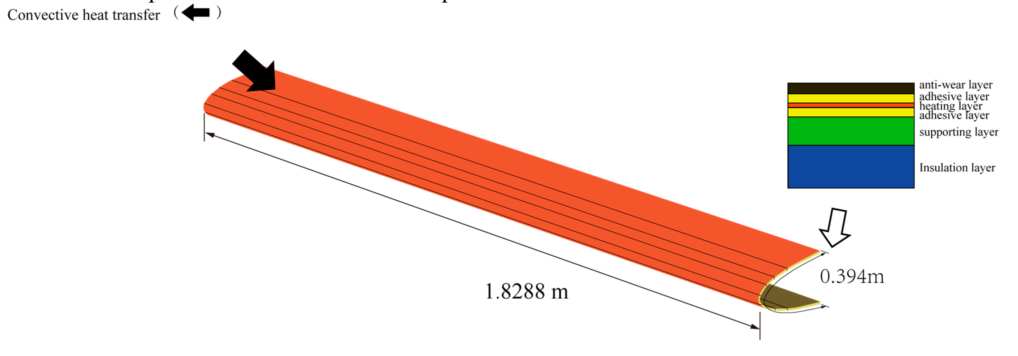
Figure 13 presents the geometric dimensions and boundary conditions of the wing leading-edge model utilized in this study. To simulate a wing fixed by rivets, the solid support boundary condition is set on the right side of the wing, constraining displacements in all three directions to zero. The corresponding constant heat source is applied at the location of the heating layer shown in
Figure 13. To simulate the atmospheric icing environment in which the electrically heated structure of the composite laminate is located, the environmental conditions, as well as the mechanical and thermophysical parameters of each layer, remain consistent with those described earlier. Both the environmental temperature and the initial temperature are set to 251.6 K.
To compare the effects of the location of the delamination damage and the size of the delamination damage on the anti-icing performance of the electrically heated wing structure, two delamination damage locations and two delamination damage areas were considered, as shown in
Figure 14.
An analysis of
Figure 15 shows that when delamination damage occurs between the wear-resistant layer and the adhesive layer, as in Case 1 and Case 4, a phenomenon similar to that observed in earlier flat composite materials is evident. In this case, the temperature in the delaminated region increases sharply. Furthermore, compared with the maximum temperature of 550 °C recorded in the previous laminated anti-icing system, the maximum temperature of the wing's electrothermal anti-icing system, which has the same delamination damage location and area, decreases to approximately 450 °C. This finding indicates that when delamination damage occurs above the electric heating layer, its impact on the wing structure is less significant than its effect on flat structures. At the same time, in this case, a high-temperature region with temperatures ranging from approximately 200 °C to 450 °C emerges around the damage. If the temperature in this region can be detected in time, further deterioration of the situation can be prevented by manually switching off the electric heating anti-icing system. A comparison of Cases 2 and 3 reveals that when delamination damage occurs between the support layer and the adhesive layer, the temperature distribution differs significantly from that observed in flat structures. Notably, the support layer and thermal insulation layer surrounding the delaminated region of the wing do not exhibit the low-temperature zones observed in the flat configuration. Compared with that under undamaged conditions, the temperature only decreases by approximately 10 °C. This is due to the influence of the curvature factor, which causes delamination damage to have a relatively small effect on curved components.
As shown in
Figure 16, a comparison of the temperature distributions for five different cases at t = 300 s and X = 0.9144 m provides significant insights. The temperature curves for the undamaged condition, Case 2, and Case 3 nearly coincide, indicating that when delamination damage occurs beneath the electric heating layer, delamination damage has less influence on the surface temperature of the wing. In contrast, comparisons of Cases 1 and 4 under undamaged conditions demonstrate that when delamination damage occurs above the electric heating layer, the surface temperature of the wing significantly varies, with the region near the centre point remaining almost unheated, whereas a marked increase in temperature is observed in the area surrounding the delaminated region on the wing surface. Moreover, a comparison with the composite flat structure in
Figure 9 shows that when delamination occurs between the corrosion-resistant wear layer and the adhesive layer and the delamination area remains constant, the peak temperature near the low-temperature region of the wing's anti-icing surface is greater than that observed in the flat structure.
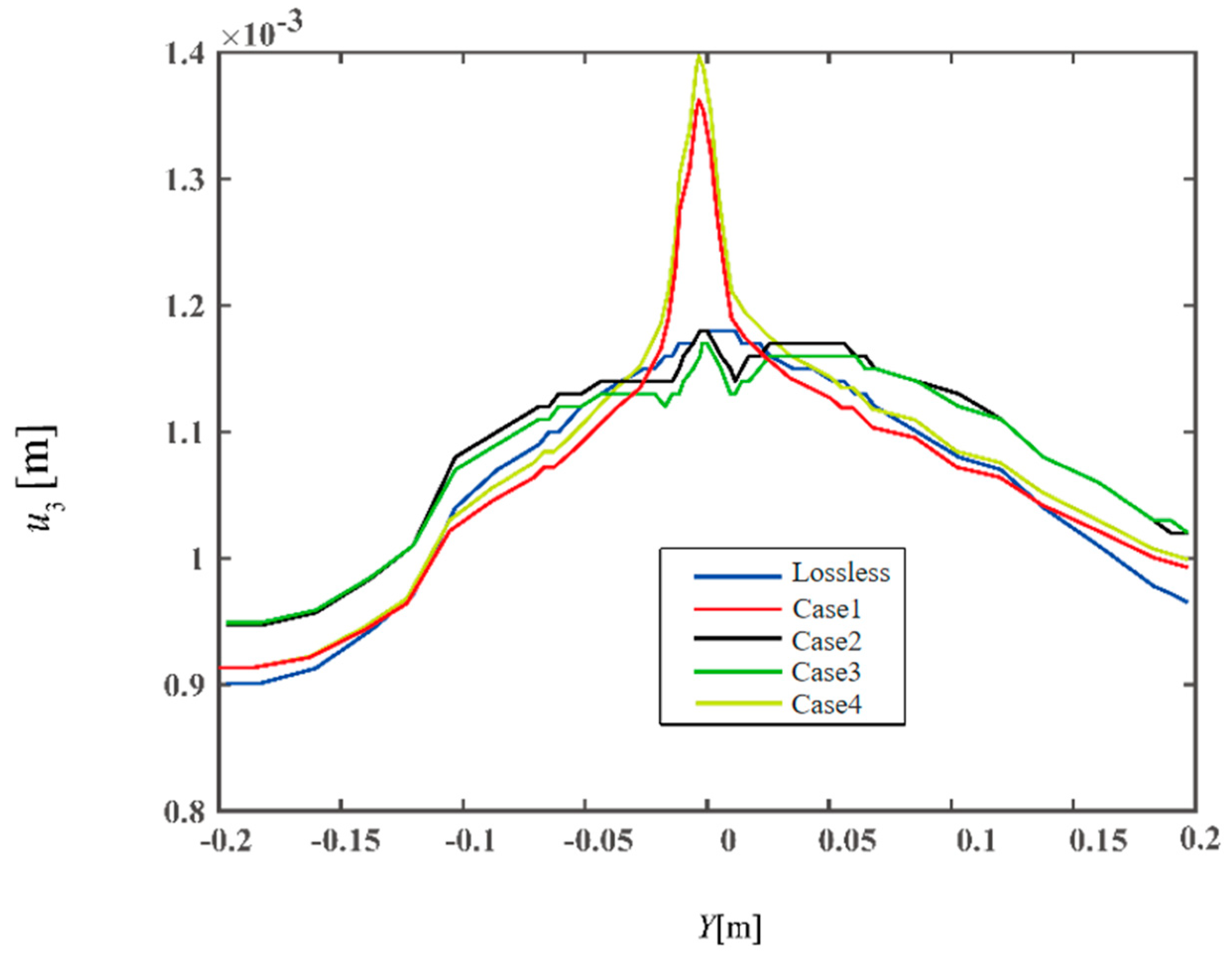
Figure 17 shows the displacement distribution in the direction perpendicular to the wing surface (u3 direction) at the position where the abscissa X is 0.9144 m after heating for 300 s for five different cases. The analysis reveals that the displacement distributions for the nondamaged case, Case 2, and Case 3 are relatively similar. However, Case 1 and Case 4 exhibit significant displacements near the centre due to thermal deformation, which is caused by the increased temperature difference resulting from delamination damage.
6. Conclusions
This study considers the heat conduction issues associated with the actual heating process, which incorporates both a constant heat source and heat flow on the anti-icing surface. This provides a supplement to the thermal expansion layer-by-layer/3D solid finite element method by deriving a new theoretical framework that accommodates the corresponding boundary conditions. The computational analysis focuses on the temperature field, displacement distribution in the axial direction, and thermal stress distribution during the electrothermal anti-icing process of preventing ice from forming on composite laminated plates with preset damage electrothermally. These findings indicate that when delamination damage occurs above the electric heating layer, the anti-icing structure in the delaminated region can be modelled as a thermal conduction case with a high-power heat source and negligible convective heat transfer, which exceeds the maximum usage temperature of the material and significantly impacts the thermodynamic performance of the structure. Conversely, when delamination damage occurs below the electric heating layer, the delamination damage has almost no effect on the temperature distribution on the anti-icing surface. Furthermore, multiple damage events have a much more pronounced effect on heat transfer obstruction, ultimately resulting in a maximum temperature that is considerably higher than that observed when considering only a single delamination event.
For aircraft wing structures with preset damage, when delamination occurs above the electric heating layer, the maximum temperature of the structure reaches 450 °C at 50 s, and the structure temperature is far greater than the material tolerance temperature. Consequently, the temperature of the anti-icing surface in the delaminated region approaches the ambient temperature, which severely reduces the anti-icing efficiency. Conversely, when delamination occurs below the electric heating layer, its impact on the temperature distribution of the anti-icing surface is negligible. Moreover, the hindrance of heat transfer due to multiple types of damage becomes more pronounced, resulting in greater detrimental effects on the structure's thermal performance.
Author Contributions
Writing—review and editing, X.H.; writing—original draft preparation, Z.W.; methodology, X.S.; data curation, H.C.; validation, J.Y.; resources, Y.N. All authors have read and agreed to the published version of the manuscript.
Funding
This research was funded by the Civil Aviation Security Capacity Building Funds of China (Grant No. ASSA2022/11) and Fundamental Research Funds for the Central Universities (Grant No. 3122024056).
Data Availability Statement
The original data contributes presented in the study are included in the article; further inquires can be directed to the corresponding authors.
Conflicts of Interest
The authors declare no conflicts of interest.
Appendix A
The unit mass matrix of the thermomechanical extended layerwise method (TELM) is given by the following equation:
The unit stiffness matrix of the TELW is given by the following equations:
The unit damping matrix of the TELW is given by the following equations:
The laminate stiffness coefficients
,
,
, and
given by the interpolating polynomials based on the revised elastic constants and thickness directions are given by the following equations:
The laminate stress temperature coefficients
and
are given by the following equations:
The thermal conductivity of the laminate
is as follows:
The cell stiffness matrix of the finite element method(FEM) is given by the following equations:
The cell damping matrix of the FEM is given by the following equations:
The cell mass matrix of the FEM is given by the following equation:
The unit displacement, temperature, and load vectors of the FEM are given by the following equations:
where
and
are given by the following equations:
References
- Lin, G.; Bu, X., Shen, X. Aircraft icing and anti-icing techniques, Beijing University of Aeronautics and Astronautics Press: Beijing, China, 2016; pp. 1–46.
- Kong,F. Analysis of the impact of icing on aircraft flight safety and protection techniques. Journal Article 2018, 69–70.
- Cao, S.; Wang, J. The development trend of low-speed impact delamination damage of composite laminates. Metallurgy and Materials 2021, 41, 139–140. [Google Scholar]
- Cheng, X. Modelling and Detection of Delamination in Plate Structures. Master's degree, Chongqing Jiaotong University, Chongqing, 2015.
- Johnson, A.; Holzapfel, M. Influence of delamination on impact damage in composite structures. Composites Science and Technology 2004, 66, 807–815. [Google Scholar]
- Li, S.; Reid, S.; Zou, Z. Modelling damage of multiple delaminations and transverse matrix cracking in laminated composites due to low velocity lateral impact. Composites Science and Technology 2004, 66, 827–836. [Google Scholar]
- Huo, L.; Kassapoglou, C.; Alderliesten, R.C. Influence of neighbouring damage on delamination growth in multiple indented composites. Materials & Design.
- Mao, Y. Analysis for Temperature Field and Thermal Stress of Composite Skin of Wings during Electrothermal Anti-Icing Process. Master's degree, Nanjing University of Aeronautics and Astronautics, Nanjing, 2018.
- Polla A; Frulla G; Cestino E. Coupled Thermo-Mechanical Numerical Modeling of CFRP Panel under High-Velocity Impact. Aerospace2023,10,.
- Tay E, T. Analysis of Delamination Growth in Laminated Composites with Consideration for Residual Thermal Stress Effects. Journal of Composite Materials 2002, 36, 1299–1320. [Google Scholar]
- Niu, Y. Lu C. Yao J. Effect of electro-thermal coupling on the residual strength of CFRP laminates containing prepositioning damage. Plastics Industry 2023, 51, 108–113. [Google Scholar]
- Reid, T.; Baruzzi, G.S.; Habashi, W.G. FENSAP-ICE: Unsteady conjugate heat transfer simulation of electrothermal de-icing. Aircr 2012, 49, 1101–1109. [Google Scholar]
- Zhengzhi W,Huanyu Z,Senyun L. Numerical Simulation of Aircraft Icing under Local Thermal Protection State. Aerospace 2022, 9, 84–84. [Google Scholar] [CrossRef]
- Morita, K.; Kimura, S.; Sakaue, H. Hybrid System Combining Ice-Phobic Coating and Electrothermal Heating for Wing Ice Protection. Aerospace 2020, 7, 102. [Google Scholar] [CrossRef]
- Shen X, Liu X, Lin G. Effects of anisotropic composite skin on electrothermal anti-icing system. Proceedings of the Institution of Mechanical Engineers, Part G: Journalof Aerospace Engineering 2019, 233, 5403–5413. [Google Scholar] [CrossRef]
- Lou Y, Bu X, Shen X. Simulation of and experimental research on rivulet model onairfoil surface. Aerospace 2022, 9, 570. [Google Scholar]
- Al-Khalil, Horvath C, Miller D, et al. Validation of NASA thermal ice protection computer codes. III-The validation of ANTICE. AIAA, Reno, NV, U.S., Jan. 6-9, 1997.
- Li, D.H.; Liu, Y.; Zhang, X. An extended layerwise method for composite laminated beams with multiple delaminations and matrix cracks. Int J Numer Methods Eng. 2015, 101, 407–434. [Google Scholar]
- Li, D.; Zhang, F.; Xu, J. Incompatible extended layerwise method for laminated composite shells. Int. J. Mech. Sci. 2016, 119, 243–252. [Google Scholar]
- Li, D.; Zhang, X.; Sze, K.; et al. Extended layerwise method for laminated composite plates with multiple delaminations and transverse cracks. Computational Mechanics, 2016, 58, 657–679. [Google Scholar]
- Li, D.; Zhang, F. Full extended layerwise method for the simulation of laminated composite plates and shells. Comput. Struct. 2017, 187, 101–113. [Google Scholar]
- Li, D. Delamination and transverse crack growth prediction for laminated composite platesand shells. Comput. Struct. 2016, 177, 39–55. [Google Scholar]
- Li, D.; Fish, J. Thermomechanical extended layerwise method for laminated composite plates with multiple delaminations and transverse cracks. Compos. Struct. 2018, 185, 665–683. [Google Scholar]
- Li, D.; Shan, W.; Zhang, F. Steady-state thermomechanical analysis of composite laminated plate with damage based on extended layerwise method. Arch Appl Mech. 2020, 90, 415–435. [Google Scholar]
- Li, D.; Ma, S. Dynamic thermomechanical analysis on composite sandwich plates with damage. Continuum Mech. Thermodyn. 2021, 33, 2167–2201. [Google Scholar]
- Morency F, Tezok F, Paraschivoiu I. Anti-icing system simulation using CANICE. Journal of Aircraft 1999, 36, 999–1006. [Google Scholar] [CrossRef]
- Benjeddou A, Andrianarison O. A heat mixed variational theorem for thermoelastic multilayered composites. Computers & Structures 2006, 84, 1247–1255. [Google Scholar]
- Li, D.; Ma, S. Study on Thermomechanical Extended-layewise/Solid-elements Method for Thermomechanical Problems of Thermal Barrier Coatings Structure with Damage. Aeronautical Science & Technology 2021, 32, 12–24. [Google Scholar]
- Yang, Y. China's aviation composites industry development outlook. Science & Technology Information 2022, 20, 161–163. [Google Scholar]
Figure 1.
Multilayer material structure for the electric heating anti-icing system.
Figure 1.
Multilayer material structure for the electric heating anti-icing system.
Figure 2.
Setting of the heating unit of the flat plate model.
Figure 2.
Setting of the heating unit of the flat plate model.
Figure 3.
Schematic of the simulation of the thermal insulation layer and other layers via the extended layer-by-layer/3D solid element method.
Figure 3.
Schematic of the simulation of the thermal insulation layer and other layers via the extended layer-by-layer/3D solid element method.
Figure 4.
Flowchart for numerical simulation of multiphysics field coupling in multilayered materials during the electric heating process.
Figure 4.
Flowchart for numerical simulation of multiphysics field coupling in multilayered materials during the electric heating process.
Figure 5.
Geometric and boundary conditions of electrically heated composite laminates.
Figure 5.
Geometric and boundary conditions of electrically heated composite laminates.
Figure 6.
Schematic diagram of the electric heating structure for composite laminates with different delamination conditions.
Figure 6.
Schematic diagram of the electric heating structure for composite laminates with different delamination conditions.
Figure 7.
Comparison of different methods for the study of the wing surface temperature distribution under Case 67A meteorological conditions.
Figure 7.
Comparison of different methods for the study of the wing surface temperature distribution under Case 67A meteorological conditions.
Figure 8.
Schematic of the simulated thermal insulation layer and other layers.
Figure 8.
Schematic of the simulated thermal insulation layer and other layers.
Figure 9.
Temperature distribution plots for the composite laminate electric heating structure with different delamination events.
Figure 9.
Temperature distribution plots for the composite laminate electric heating structure with different delamination events.
Figure 10.
Comparison of the temperature distributions at time t=300 s and X=0.9144 m.
Figure 10.
Comparison of the temperature distributions at time t=300 s and X=0.9144 m.
Figure 11.
Electrically heated composite laminates with multiple delamination damage events.
Figure 11.
Electrically heated composite laminates with multiple delamination damage events.
Figure 12.
Temperature distribution of electrically heated composite laminates with multiple delamination damage events.
Figure 12.
Temperature distribution of electrically heated composite laminates with multiple delamination damage events.
Figure 13.
Schematic of an electrically heated wing structure.
Figure 13.
Schematic of an electrically heated wing structure.
Figure 14.
Electric heating structures for wings with different degrees of layered damage.
Figure 14.
Electric heating structures for wings with different degrees of layered damage.
Figure 15.
Temperature distribution of electrically heated wing structures with different layers.
Figure 15.
Temperature distribution of electrically heated wing structures with different layers.
Figure 16.
Comparison of the temperature distributions at time t=300 s and X=0.9144 m.
Figure 16.
Comparison of the temperature distributions at time t=300 s and X=0.9144 m.
Figure 17.
Comparison of the displacement distributions of the perpendicular direction (u3), when t=300 s and Y =0.9144 m.
Figure 17.
Comparison of the displacement distributions of the perpendicular direction (u3), when t=300 s and Y =0.9144 m.
Table 1.
Physical parameters of each layer of material.
Table 1.
Physical parameters of each layer of material.
| |
λx
W/(m·K) |
λy
W/(m·K) |
λz
W/(m·K) |
ρ
kg/m3 |
Cp
J/(kg·K) |
| wear-resistant layer |
16.265 |
16.265 |
16.265 |
8026 |
502.4 |
| adhesive layer |
0.256 |
0.256 |
0.256 |
1384 |
1256 |
| electric heating layer |
41 |
41 |
41 |
8907 |
385.2 |
| support layer |
0.294 |
4.4 |
0.294 |
1796.5 |
1570 |
| thermal insulation layer |
0.121 |
0.121 |
0.121 |
648.8 |
1130.4 |
Table 2.
Heating unit parameters.
Table 2.
Heating unit parameters.
| Heating Unit |
F |
D |
B |
A |
C |
E |
G |
| X-direction width (m) |
0.0381 |
0.0254 |
0.0254 |
0.01905 |
0.0254 |
0.0254 |
0.0381 |
| Electric heating power per unit volume (109) |
1.587 |
1.709 |
2.563 |
3.417 |
2.074 |
1.465 |
1.465 |
| Heating Unit |
F |
D |
B |
A |
C |
E |
G |
Table 3.
Mechanical properties of each layer of material.
Table 3.
Mechanical properties of each layer of material.
| |
Elastic modulus
(GPa) |
Liner coefficient of thermal expansion(α×10-6/℃) |
Poisson’s ratio |
| wear-resistant layer |
193 |
16.5 |
0.29 |
| adhesive layer |
0.0078 |
200 |
0.49 |
| electric heating layer |
206 |
13.3 |
0.28 |
| thermal insulation layer |
3 |
40 |
0.35 |
Table 4.
Mechanical properties of support layer.
Table 4.
Mechanical properties of support layer.
| |
Elastic modulus
(GPa) |
Liner coefficient of thermal expansion(α×10-6/℃) |
|
Shear modulus
(GPa) |
Poisson’s ratio |
| X |
10 |
17.8 |
XY |
5 |
0.3 |
| Y |
45 |
4.9 |
YZ |
5 |
0.3 |
| Z |
10 |
17.8 |
XZ |
3.8 |
0.4 |
Table 2.
Mechanical properties of each layer of material.
Table 2.
Mechanical properties of each layer of material.
| Case |
67A |
| V∞, m/s |
89.4 |
| T∞, ℃ |
-21.6 |
| LWC, g/m3
|
0.55 |
| MVD, μm |
20 |
| Angle of attack, α |
0 |
|
Disclaimer/Publisher’s Note: The statements, opinions and data contained in all publications are solely those of the individual author(s) and contributor(s) and not of MDPI and/or the editor(s). MDPI and/or the editor(s) disclaim responsibility for any injury to people or property resulting from any ideas, methods, instructions or products referred to in the content. |
© 2025 by the authors. Licensee MDPI, Basel, Switzerland. This article is an open access article distributed under the terms and conditions of the Creative Commons Attribution (CC BY) license (http://creativecommons.org/licenses/by/4.0/).