
Submitted:
17 February 2025
Posted:
17 February 2025
You are already at the latest version
Abstract
Radio-frequency (RF) microwave wireless power transfer (WPT) offers an efficient means of delivering energy to a wide array of devices over long distances. Previous RF WPT systems faced significant challenges including complex hardware and control systems, software deficiencies, insufficient rectification power, lack of high-performance substrate materials, and electromagnetic radiation hazards. Addressing these issues, this paper has proposed the world’s first watt-level RF WPT system capable of intelligent continuous tracking and occlusion judgment. Our 5.8 GHz band RF WPT system integrates several advanced technologies such as the millimeter-precision lidar, the multi-object image recognition algorithm, the accurate 6-bit continuous beamforming algorithm, the compact 16-channel 32 W high-power transmitting system, a pair of ultra-low axial ratio circularly polarized antenna arrays, ultra-low-loss high-strength ceramic substrates, and a 2.4 W high-power Schottky diode array rectifier achieving a rectification efficiency of 66.8%. Additionally, we constructed a platform to demonstrate the application of the proposed RF WPT system in battery-free vehicles, achieving unprecedented 360∘ uninterrupted power supply to the battery-free vehicle. In summary, this system represents the most functionally complete RF WPT system to date, serving as a milestone for several critical fields such as smart living, transportation electrification, and battery-less/free societies.
Keywords:
RF WPT
; MPT
; wireless charging
; rectifier
; antenna array
; auto-tracking
; AI
; wireless power transfer
1. Introduction
Wireless Power Transfer is an attractive method of transferring energy without physical contact, offering convenience and the possibility to power many electrical devices. Especially now, with various electronic devices and new-energy electric vehicles that require a large number of batteries, the issues of resource consumption and environmental pollution associated with batteries still need to be addressed urgently [1]. Therefore, battery-free or battery-light solutions are of great significance to society as a whole. Smart living represents another excellent application scenario for RF WPT, as illustrated in Figure 1. This technology enables us to eliminate cluttered charging cables and achieve genuine wireless charging, which brings significant convenience. There are many ways of WPT at different power levels and different distances [2], since RF electromagnetic waves can propagate over long distances in a vacuum or in air and are therefore considered one of the most effective means of far-field WPT.
RF WPT has a long history. However, due to certain limitations such as low efficiency, high cost, complex systems, and potential radiation hazards, it has not been commercialized on a large scale [5]. A typical beamforming RF WPT system consists of several components, including the RF source, power divider, phase shifter, attenuator, rectifier, transmitting (Tx) and receiving (Rx) antenna, and a dc power management system [6]. Some recent works have also introduced the application of metasurfaces in RF WPT, which has broadened the scope of RF WPT applications and represents one of the potential development paths for the future [3,4]. However, most current research focuses on rectifiers or rectennas, which are devices used to harvest RF energy and convert it to dc power. Based on the different components of the rectifier device, they can be mainly categorized into three types: GaAs Schottky diode rectifiers [7,8,9,10,11,12], GaN Schottky diode rectifiers [13,14,15,16], and GaN transistor rectifiers [17,18,19,20]. GaAs Schottky diodes are more suitable for low-power applications such as the Internet of Things (IoT) due to their high efficiency and low cost, and they are also the most popular commercially available components for WPT applications. Compared to GaAs rectifiers, the maximum rectification power of GaN transistor rectifiers is significantly higher, often exceeding 10 W, while maintaining high efficiency at high power levels. However, they also have notable disadvantages: the self-driving GaN transistor rectifier is much larger than the GaAs Schottky diode rectifiers [18], and GaN transistors are very expensive. In addition, GaN Schottky diodes are almost not commercially available, posing challenges for future large-scale applications.
The design of the Tx and Rx antennas is crucial because circularly polarized (CP) antennas are not sensitive to changes in the relative orientation of the Tx and Rx antennas, which can be employed in far-field WPT. A pair of antennas with high gain and a low axial ratio can effectively reduce energy loss, therefore, a massive Tx antenna array combined with efficient beamforming algorithms is a feasible solution. Traditional commercial RF substrates often struggle to withstand high RF transmission power, suffer from high dielectric losses, and are prone to deformation as a result of heating. However, preparing large-area low-loss substrates is very challenging, highlighting the need for higher-performance materials for use in Tx antenna substrates. The design of an efficient and intelligent RF WPT system is also complex, costly and challenging, resulting in few complete WPT systems with tracking functions in current research [21,22,23,24,25,26]. An auto-tracking far-field WPT system operating at a 5.8 GHz frequency is proposed in [21]. This system employed a backscattered pilot signal to achieve energy focusing, allowing Rx nodes to operate without batteries. However, the Rx node requires a complex activation circuit and a backscattering module for communication, which significantly increases the power consumption and complexity of the Rx nodes. Time reversal is another method to achieve WPT, as it can provide high-efficiency energy focusing over various distances and enable quasi-continuous wave WPT [22]. Nevertheless, the receiver must also be equipped with a complex communication module, and a significant challenge is that its communication and pilot signals occupy a certain amount of time within a charging cycle. This means that when the receiver moves quickly, the received power decreases throughout the charging cycle. To improve tracking speed, the charging cycle must be shortened, which increases the proportion of communication time and reduces efficiency. Other methods to obtain the Tx phases include angle tracking [24], retroreflective methods [23], and retrodirective methods [25]. However, these methods face issues such as redundancy and power consumption of the communication module, poor speed and accuracy of the tracking system, limited rectification power, and difficulty in identifying obstructions on the power transmission path.
The emergence of artificial intelligence systems has enabled real-time object tracking. More recently, Bo Yang et al. proposed an auto-tracking WPT system based on image recognition and beamforming technology [26]. The main advantage of their work compared to others is that the position of the Rx device is estimated using a camera, eliminating the need for communication modules at the Tx and Rx ends, which is crucial for the miniaturization of Rx devices. Since the digital phase shifter is only 4-bit with accuracy, the entire working area was divided into several sections according to the 1-D angle. However, their work had several shortcomings, such as the requirement to know the true size of the charged object to accurately calculate the Z coordinates, the insufficient number and accuracy of phase shifters that only allowed for rough 1-D scanning, the inability to detect human body occlusion and re-track after losing the target, and the absence of rectifiers in the design.
In this paper, we develop a truly intelligent auto-tracking RF WPT system, which is the most advanced multi-field RF WPT system compared to existing works. It can be directly applied to charge various devices in our daily lives, particularly in complex environments where people are present, achieving a level of intelligence and versatility akin to commercial-grade devices. We also demonstrate a dynamic RF WPT system designed for battery-free vehicles, showcasing the superiority of our designed system. The entire system features several highlights, including:
- Design of a 16-channel high-power microwave Tx system for RF WPT.
- A high performance ceramic Tx antenna array, and a compact multi-layer circularly polarized Rx antenna array.
- Multi-object recognition and tracking algorithm based on deep learning, which can accurately detect human obstruction, and recover tracking of the original quickly after target losing.
- MM-level precision lidar positioning system based on spatial projection algorithm.
- Efficient beamforming algorithm, and the integration of the object information system, object tracking system, occlusion judgment system, target re-tracking system, and energy focusing algorithm into a user interface (UI).
- Extremely compact high-efficiency 2.5W-level Schottky diode rectifier.
2. Principle and Methods
Framework of the Proposed RF WPT System
The proposed RF WPT system is composed of three main parts: the Tx end, the Rx end, and the intelligent algorithm system. The overview and principle of our proposed RF WPT system is shown in Figure 2. At the Tx end, an RF signal source generates continuous RF waves at 5.8 GHz band, which are then fed into a 16-way power divider. Each output port of the power divider serves as an individual Tx channel, where a digital attenuator and a digital phase shifter are employed to control the phase and amplitude of the RF waves. A RF power amplifier follows the digital phase shifter, with its output port serving as the Tx channel’s output. Given that the system is intended to charge various electronic devices placed randomly, it is essential to have a pair of low axial ratio Tx and Rx phased array antennas to effectively transmit energy in any relative direction. In our proposed system, we designed a sequentially rotated low axial ratio 64-element Tx antenna array to generate left-handed circularly polarized (LHCP) waves, with four antenna elements being fed by one Tx channel.
The aforementioned devices constitute the Tx end of the system. At the Rx end, a 16-element, multi-layer, LHCP microstrip Rx antenna array is employed to minimize polarization loss and reduce antenna size. This configuration ensures a low axial ratio and maintains a compact size. All the energy received by the Rx antenna is collected by a power combiner located at the base of the Rx antenna array. Subsequently, the combined RF energy is directed into a compact high-power rectifier, where it is converted into dc power for charging batteries or powering motors in battery-free devices.
In addition to the Tx and Rx ends, the intelligent algorithm system also plays a crucial role, and the process begins with object identification and classification. An RGB camera captures streaming video, and each frame is transmitted to a pre-trained convolutional neural network model for object recognition. Once multiple objects are recognized simultaneously, the next step involves locating them using a lidar module, which generates a point cloud to obtain the Z0 depth information of the current image frame. A spatial projection algorithm is then employed to derive the 3D coordinate information, where Z0 is used as the known input parameter to calculate the unknown X0 and Y0 parameters. At this stage, the classification and location information of all objects is established, allowing a WPT target to be selected on the computer screen. With the assistance of object tracking and tracking recovery algorithms, the intelligent RF WPT system can continuously track the specified target. Additionally, the occlusion judgment algorithm helps prevent human exposure to high-power RF waves, which is critically important for safe daily use.
In the subsequent step, the continuous 3D coordinates of the tracked object are used as input parameters for the beamforming algorithm. Given that the digital phase shifter and digital attenuator operate on discrete values, it is essential to convert the calculated optimal phase and amplitude values into the nearest achievable discrete values by our proposed the nearest neighbor interpolation method. The computer then sends commands to the Tx system to control the direction of the energy beam accordingly. These components collectively form the framework of our proposed RF WPT system.
Tx System
In the proposed RF WPT Tx system, the output power of the signal source is 5.0 dBm in 5.8 GHz band, and it is connected to a 16-channel power divider. Within each Tx channel, a 6-bit digital attenuator with a minimum step of 0.5 dB and a 6-bit digital phase shifter with a minimum step angle of are employed. These components operate on fixed discrete values, with each capable of achieving 64 different settings. When the computer sends a command value by the beamforming algorithm, it is necessary to select the closest match from these 64 discrete values as the final Tx attenuation and phase shift setting. Data transfer between the Tx system and the computer is carried out via the UART protocol over an asynchronous RS-422 link, with a transmission rate of 921,600 bps. At the output port of each Tx channel, an RF power amplifier with a gain of 40.0 dB and a maximum output power of 2.0 W (33.0 dBm) is used to transmit energy to the Tx antenna.
Tx and Rx Antenna Array
The design of the Tx and Rx antennas emphasizes high gain, low loss, and a low axial ratio to maintain high transmission efficiency in any direction over long distances. A sequentially rotated feeding CP antenna is an effective approach to achieving low axial ratios in large-scale antenna arrays [27,28,29]. In this method, a patch antenna is physically rotated three times by around a central point to create a 4-element antenna sub-array, with the feeding phases of each patch differing sequentially by . As shown in Figure 3a,b, four Tx antennas within a sub-array are connected to a ring power divider in our design (the detailed methods can be seen in Appendix A.1). The four ports of the ring power divider output equal power with phase differences of , allowing 16 Tx channels to control 64 Tx antennas for enhanced energy focusing. Each 4-element sub-array undergoes three rotations to form a 16-element antenna array, additionally, the input phase of each sub-array also differs sequentially by . By replicating this 16-element array to expand it into a 64-element array, an ultra-low axial ratio CP Tx antenna array is achieved. The spacing between each patch antenna is approximately half the wavelength of the 5.8 GHz electromagnetic wave (26.0 mm).
To address issues of high loss, low power capacity, and potential beam deviation due to thermal bending commonly observed in commercial high-frequency substrates, we have independently designed and utilized the tape casting method to fabricate a super-low loss alumina ceramic substrate. This substrate features a thickness of 0.6 mm, a dielectric constant of , a dissipation factor (at 10 GHz), and a bending strength exceeding 600 MPa. The outstanding characteristics of this material ensure efficient and stable operation of the Tx antenna array at high power levels for extended periods, with minimal deformation. Each Tx antenna sub-array is fed from the metal pin using a SubMiniature version A (SMA) connector on the bottom layer, with the SMA connected to one channel of the Tx system via RF coaxial cable. The size of the cutting corner of the metal pattern on the top layer and the feeding position can be adjusted to ensure a lower axial ratio and return loss simultaneously, which is effective in designing large-scale CP antenna arrays. As shown in Figure 3e, the single 4-element sub-array Tx antenna achieves a minimum return loss of S11< -33.8 dB at 5.75 GHz. The overall Tx antenna array achieves a high gain of 26.5 dB, and the center axial ratio is less than 0.057 dB, which are almost perfect CP waves, demonstrating that the Tx antenna array can efficiently transmit LHCP waves to the target.
At the Rx end, a 4×4 LHCP antenna array is utilized to harvest RF energy, as shown in Figure 3c,d. This array employs a similar cutting-corner and bottom feeding patch antenna design with 20.0 mm spacing on the top layer. The collected power flows into a 16-way power combiner on the bottom layer through metallized vias. The multilayer structure consists of 7 layers: 4 metal layers and 3 dielectric layers. From top to bottom, these layers include the antenna pattern layer, a 0.508-mm-thick Rogers 4003C layer, a grounding (GND) layer, a 0.1-mm-thick FR-4 Prepreg (PP) layer, another GND layer, a second 0.508-mm-thick Rogers 4003C layer, and a power combiner layer. The Rogers 4003C layer has a relative dielectric constant of and a dissipation factor , while the PP layer has a relative dielectric constant of and a dissipation factor . The combined RF energy is output to the rectifier via an SMA connector. As shown in Figure 3g, the Rx antenna array achieves a return loss of S11< -17.5 dB at 5.75 GHz. The Rx antenna also achieves a gain of 14.2 dB and the center axial ratio is measured to be less than 2.2 dB.
Rectifier
Rectifiers are key components that influence the overall efficiency of RF systems. Due to the large size and high cost of transistor-based rectifier circuits, they are not suitable for most common electronic devices. However, many other designs based on Schottky diodes are limited by circuit configuration and power capacity, with rectification power rarely exceeding 1 W. Our rectifier design offers three main advantages: ultra-compact size, high power capacity, and high efficiency. The rectifier uses a 0.252-mm-thick Rogers 5880 substrate and a 47 pF capacitor as a dc block. The Rogers 5880 substrate has a relative dielectric constant of and a dissipation factor . Two HSMS-282L Schottky diodes from Broadcom are soldered between the microstrip transmission line and the ground (GND) plate. Each HSMS-282L component contains three individual parallel-connected Schottky diodes, totaling six diodes. As shown in Figure 4b,c, the circuit consists of a dc pass filter, a transformer, a GND plate, and an impedance matching network. The dc pass filter suppresses the fundamental frequency (5.8 GHz) RF wave and its and harmonics, reflecting them back into the Schottky diode for re-rectification to enhance efficiency (please refer to Appendix A.3). The stub length is approximately of the corresponding harmonic frequency, and a transformer is used to minimize energy loss. The impedance matching network matches the impedance of Schottky diodes to and includes two stubs for harmonic suppression at and . The GND pad of the Schottky diode is connected to the bottom metal layer by a metallized via for improved grounding. As shown in Figure 4d, the maximum measured efficiency is with an input power of 2400 mW and a load resistance of . The efficiency remains above for input powers ranging from 200 mW to 4000 mW, demonstrating high efficiency at high input power levels.
Object Information System
The overview of the intelligent algorithm is shown in Figure 5. The object information system consists mainly of two systems: the object classification system and the object positioning system. The object classification system is based on the YOLOv5 deep learning computer vision model [30,31]. This model is capable of recognizing most common objects and can be re-trained to recognize uncommon objects, such as receiving antennas, while maintaining a high processing frame rate. We utilize both object detection and instance segmentation functions, and when a colored video stream is input to the computer, it is divided into individual frames for processing. First, all objects in the RGB image are recognized and classified, and the area containing each recognized object is delineated with a bounding box in the image.
In our system, we use an D435i depth camera to capture colored video streams and depth information. Compared to positioning systems in other works [21,22,23,24,25,26], our proposed lidar positioning system achieves a significantly higher positioning accuracy of less than 2% at a distance of 2 m and supports a higher frame rate of up to 90 frames per second. Additionally, it does not require any communication module in the Rx devices, which enables the possibility to flexibly and conveniently charge objects of various types and power levels and is also suitable for high-speed moving objects.
The next step involves using the object positioning system, which is based on the spatial projection algorithm, to obtain the precise 3D spatial coordinates of all recognized objects. As shown in Figure 4a, the lidar is placed at a distance of below the center of the Tx antenna array, with its optical axis kept parallel to the normal direction of the Tx antenna board. The focal distance of the image plane obtained by the RGB camera is , a known parameter, and the coordinates of the object on the image plane are represented by the geometric center position of the bounding box. Since the lidar obtains the depth coordinate of the object via the point cloud, rather than absolute coordinates, the key is to use the RGB image information and the depth information to calculate the actual and coordinates of the object. Equation (1) can be used to calculate and based on the triangle similarity theorem.
The 3D spatial coordinates of the object relative to the center of the Tx antenna can be expressed as . All classification information and 3D coordinates of the recognized objects are then output to the object tracking system for further processing.
Object Tracking System
In daily life, continuously transferring power to a target object using an RF WPT system is challenging due to issues such as occlusion and target loss. Currently, no RF WPT system can continuously track a target while preventing human exposure to high-power RF radiation. To address this, we have designed an intelligent object tracking system, which consists of three subsystems: object tracking, occlusion judgment, and tracking recovery.
In the object tracking subsystem, the classification information and 3D spatial coordinates of all recognized objects are displayed on the real-time RGB video stream. Users can select any recognized object using the mouse, and a screenshot of the selected area is stored and displayed on the UI. The system calculates the distance between the center of the selected area and all recognized objects, automatically selecting the object with the smallest distance for tracking. The Intersection over Union (IoU) algorithm [32], as shown in Equation (2), is used to calculate the intersection ratio of two images. The IoU between the tracked object and all recognized objects with the same classification label is calculated in each frame, and the object with the highest IoU value is selected to achieve high-speed continuous tracking. The principle behind this is that the position difference of the same object in adjacent frames is minimal, resulting in significant overlap of detection boxes and a larger IoU.
In the occlusion judgment subsystem, if the tracked object suddenly disappears, the system records the last frame of the object within the bounding box area and sends a command to the Tx system to maximize the attenuation values of all digital attenuators, thereby minimizing power transmission. Another scenario occurs when people enter the charging zone, causing the bounding box of `people’ to overlap with that of the tracked object. In this case, in addition to adjusting the Tx attenuation to the maximum, the system issues an alarm to warn people to stay clear of the charging zone.
The tracking recovery subsystem aids in re-tracking the object after it is lost, employing two algorithms. The previously mentioned IoU algorithm can be utilized when the position and direction of the tracked object do not change significantly upon reappearance. However, if there are substantial changes in distance and orientation, inaccuracies in target recovery may occur. To enhance re-tracking accuracy, a hashing method is employed to compare figure similarity, as discussed in [33]. Specifically, the difference value hash (dHash) algorithm is used to facilitate fast and accurate searching of the disappeared target, as shown in Figure 5.
The aforementioned algorithm enables the RF WPT system to continuously output the 3D spatial coordinates of the tracked object across various complex scenarios, making it extremely practical.
Beamforming Algorithm
If the antenna array has i rows, j columns and k layers, for a single-layer planar antenna array (k = 1), the 3D spatial coordinates of the ai,j,k antenna element relative to a1,1,1 can be expressed as
Then the 3D location matrix of antenna elements can be written as , . For the object located at (X, Y, Z), its distance matrix to each antenna element can be written as
When converting the distance matrix to a phase matrix , a negative sign is needed to indicate that the farther the antenna element is from the target, the earlier the transmission needs to occur. The phase matrix can be calculated, as shown in Equation (5).
For convenience, the phase matrix is converted to a phase difference matrix relative to , and the radians of all elements in are converted to angles in the range of 0 - . Then the calculated phase shift angle matrix can be obtained, Equations (6) - (7) show the above processes.
Since the matrix represents only a theoretical calculation result, it must be converted into a matrix that can be implemented in the Tx system. Most other studies have achieved this by dividing different WPT regions, as seen in references such as [24,26,34]. However, this method has limited spatial resolution and poor tracking ability. We propose using the nearest neighbor interpolation method for matrix conversion to ensure that the phase shift values are as close as possible to the calculated results. For an n-bit precision digital phase shifter, the possible angle value matrix is presented in Equation (8). Each element in is replaced by the nearest value in to form a new matrix . The argmin function is employed in Equation (9) to achieve the desired conversion.
The equation above elucidates the principle of the beamforming algorithm, which theoretically applies to any planar antenna array. Given that the antenna we designed includes four antenna elements within the same subarray, all fed by a single Tx channel, it is necessary to treat the entire subarray as a single antenna element during the calculation process. Ultimately, the phase matrix must be combined with the /// Tx phases required by the sequentially rotated array. This combined matrix is then converted into machine code and transmitted to the Tx system via the UART protocol over an asynchronous RS-422 link. Furthermore, the attenuation matrix (0 dB for WPT or 50 dB for protection) is also transmitted, thus completing the WPT process.
Results
In this section, we carried out experiments to demonstrate the outstanding performance of the proposed system, and photographs of the RF WPT system are shown in Figure 6. Except for the signal source and Tx antenna array, all Tx components were integrated into a single metal chassis. The Rx system consists of the Rx antenna array and rectifier, which are connected by SMA connectors. The RF WPT experiment was conducted in the microwave anechoic chamber for system-level measurements, as shown in Figure 6f. Taking into account the actual S-parameters of the Tx and Rx antennas, the system ultimately operated at 5.75 GHz (in 5.8 GHz ISM band). To protect the test equipment, the attenuation value of all channels was first adjusted to -30 dB. Then, using computer commands, the main beam deflection angle was varied from to in increments. After each angle adjustment, the scanning frame equipped with a waveguide probe was used to perform a scan at a distance of 5. Once the scan was completed, the probe was rotated and scanned again. The field strength and phase at each point were recorded to calculate the two-dimensional radiation pattern and axial ratio of the Tx array antenna. Figure 7 shows the measured results of the 2-D radiation pattern.
To measure the rectified dc power, the attenuation of all channels was adjusted to 0 dB, allowing the output power of the Tx system to reach its maximum. Then, the receiver was replaced with the Rx antenna and rectifier. The two ports of the rectifier were connected to the input and output ports of the electronic load (ITECH 8511A), respectively, with the load resistance set to . The voltage values displayed on the electronic load at different relative distances and angles between the Tx and Rx antennas were recorded, and the dc power was calculated, as shown in Figure 6g. It was observed that when the beam was at , the system’s WPT efficiency was highest. Due to the inherent aperture of the Tx antenna array, the received power reached its maximum at approximately .
Figure 8 illustrates the usage process of the user interface. The calculated phase values matrix , the commanded phase values , and the command codes are displayed in the black area. The photo of the tracked object is shown in the green area, the tracked object information and warning system is displayed in the red area, the accurate position coordinates of the tracked object are presented in the blue area, and the object information system is depicted in the colored RGB video stream. When charging electronic devices, the user simply needs to select an object on the screen, which can then be auto-tracked continuously, even if it is blocked by the human body or other objects and reappears at different positions. The system also automatically warns people to stay away from the WPT area, fundamentally mitigating the risk of human exposure to electromagnetic waves, thereby offering great practical value.
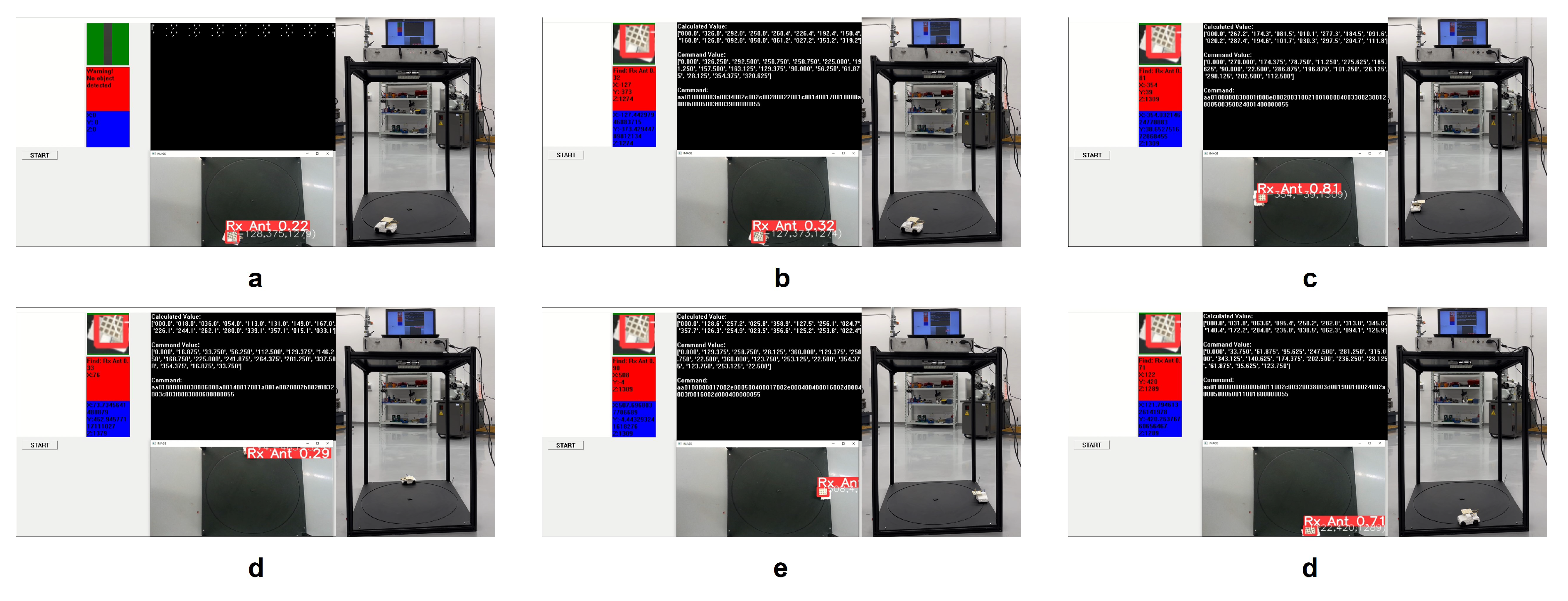
To demonstrate the strong practicality of our proposed system, we constructed a far-field WPT demonstration platform for battery-free vehicles. The Tx system and antenna array were placed above the platform, and a battery-free vehicle was positioned on a track with a diameter of 90 cm below, at a vertical distance of 130 cm from the Tx antenna. When the system was activated, all information about the Rx antenna was displayed on the UI interface, as shown in Figure 9 (refer to the video in the Supplementary Video). After selecting the Rx antenna with the mouse, the vehicle immediately started running and could maintain continuous operation in any orientation. This experiment fully demonstrated the stability of our proposed WPT system in transmitting energy to objects in any relative position.
Discussion
The maximum received power of existing auto-tracking RF WPT systems has been below 600 mW, and their intelligence level was relatively low [21,22,23,24,25,26]. Most systems also required complex circuits at the Rx end for localization. Compared to systems in other papers, our proposed system did not require any communication modules at the Rx end. It is currently the only auto-tracking RF WPT system that has achieved a watt-level dc power for home-use, and its level of intelligence and safety is unprecedented. This work encompassed numerous innovations in devices, materials, algorithms, and systems. For contemporary society, RF WPT is undoubtedly highly attractive, whether in the context of smart living, intelligent transportation, low-altitude economy, and battery-free society. The core of this work is not to pursue the optimal performance of each component, but rather to establish an innovative, mature, versatile, and user-friendly system.
It can be observed from Figure 7 that when the beam deflection angle was , the majority of the energy was focused within the region, achieving a good focusing effect for the electromagnetic wave. When the deflection angle reached , the energy of the side lobes began to approach the intensity of the main beam. This was because, to achieve efficient WPT in any relative orientation, we employed the sequentially rotated antenna design with ultra-low axial ratio mentioned earlier. This method offered extremely high transmission efficiency at non-large deflection angles, but it could cause side lobe issues at large deflection angles. However, since our system primarily operated in the far field, the scanning range was sufficient to cover a large area. In addition, our human protection system was effective only for the main beam. When the scanning angle is too large, sidelobes may inevitably pose potential radiation risks. Therefore, to ensure the absolute safety and reliability of the RF WPT system, the scanning range should not be excessively large. To further enhance beam directivity, larger aperture antenna arrays and more antenna elements should be used.
Since the Rx antenna array we designed was extremely compact, as the distance increased, the proportion of the Rx antenna’s area within the main beam’s projection area rapidly decreased, leading to a significant drop in rectified dc power. The received phase of each antenna element in the Rx antenna array is different and uncontrollable, so having too many antenna elements may cause electromagnetic waves to cancel each other out, reducing the total received power. To further enhance the received power, it is preferable to use multiple rectennas. For the rectifier, as power increases, thermal losses can significantly rise, leading to greater discrepancies between measured and simulated results. However, since the antenna area is limited in practical use, high thermal losses are unlikely at lower power levels in the Rx end. Therefore, the power range of our proposed rectifier is reasonable.
Hardware and System
The metal layers of the Tx and Rx antennas are copper layers with a thickness of m, and their surfaces are treated by the immersion gold process. During the WPT experiment, the SG6-A portable RF signal source was used, and the Keysight U2002A USB Power Sensor was employed as the power meter to measure all the RF power in the experiment. When measuring the RF power of the Tx output channel, a Keysight 773D Coaxial Directional Coupler and a -40 dB adjustable attenuator were used to protect the RF power sensor. Due to the difficulty of fabricating ultra-thin ceramic substrates larger than 20 cm × 20 cm using the tape casting method, we divided the substrate into four equal pieces. After production, these pieces were bonded to a 1 mm thick stainless steel plate, and circular patterns were laser-cut for the placement of SMA connectors, as shown in Figure 6e.
In the demonstration experiment for the battery-free vehicle, we constructed a frame using aluminum profiles and placed 1.0 cm thick acrylic panels on both the top and bottom. The Tx system was mounted on the top panel, which had a laser-cut square hole at its center to allow RF coaxial cables to connect the Tx system to the Tx antenna array below. Positioned close to the antenna, the lidar was oriented vertically towards the track plane. This track plane consisted of two stacked acrylic panels, with the top panel featuring a laser-cut circular pattern. A bearing on the underside of the vehicle chassis fit into this circular groove, enabling the vehicle to move continuously along the track.
Software
All the software was developed using Python and NVIDIA CUDA. Our object recognition system is built on the COCO 128 dataset, with an additional model specifically for recognizing the Rx antenna. To accomplish this, we captured and annotated 300 images of the Rx antenna. We then conducted 300 training iterations with this dataset, which enabled reliable recognition of the Rx antenna at any position on the track. During the training and experimentation process, we achieved a recognition rate of over 90 frames per second using only a mobile NVIDIA GTX 1070 graphics card. This performance makes the system well-suited for applications involving high-speed moving targets.
As shown in Figure 9, once the Calculated Values are determined, the Command Values need to be converted into a hexadecimal command to be sent to the Tx system. The command code begins with the fixed initial bytes `aa 01 00’. Following this, every four characters represent the hexadecimal phase and attenuation values for each channel. For example, `00 00’ corresponds to a phase of and an attenuation of 0 dB, while `01 01’ corresponds to a phase of and an attenuation of 0.5 dBm, and so forth. The command ends with the fixed bytes `00 00 55’.
When measuring the 2-D far-field radiation pattern, the waveguide probe performs repeated scans in the X-Y plane. To ensure stable measurement results, we set fixed phase and attenuation values for each channel of the Tx system using the testing software before commencing measurements. This testing software is distinct from the intelligent tracking algorithm utilized in the main software.
Conclusions
In this paper, the superiority and practicality of the system was fully demonstrated, representing a significant milestone in WPT applications. In the future, we expect higher efficiency, higher power and smarter systems to become available.
Supplementary Materials
The following supporting information can be downloaded at the website of this paper posted on Preprints.org.
Author Contributions
Z.Y., C.H. and W.W. initiated the research and designed the experiments; Z.Y. and C.H. designed and manufactured the Tx ceramic antenna array; Z.Y. and B.H. measured and analyzed the data with W.J.; Z.Y. designed the automatic tracking software and conducted all the simulations. Z.Y. and W.J. designed and manufactured the battery-free vehicle RF WPT demonstration platform; All the authors contributed to the writing of the manuscript.
Funding
This work was supported by the Natural Science Foundation of China (NSFC) (Grant No. 12074279).
Data Availability Statement
The data that support the findings of this study are available from the corresponding author upon reasonable request.
Acknowledgments
The authors thank Wave Functional Metamaterial Research Facility (WFMRF) in the Hong Kong University of Science and Technology (Guangzhou) for instrumental support.
Conflicts of Interest
Authors declare that they have no competing interests.
Appendix A
Appendix A.1. Design of the Tx Antenna Array
The Tx antenna subarray consists of four patch antennas, with their detailed dimensions labeled in Figure A1.
Figure A1.
Geometric dimensions of the Tx antenna subarray from (a) top view and (b) rear view
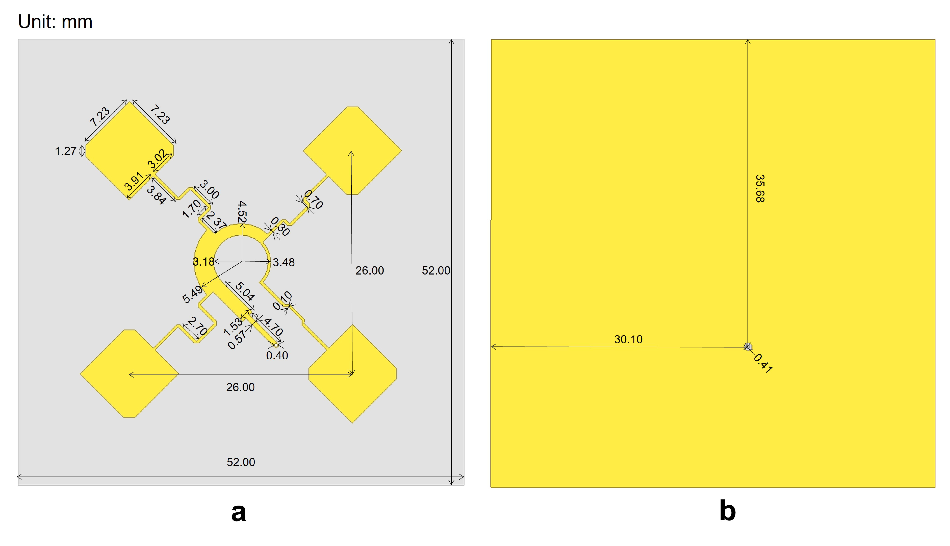
The sequentially rotated Tx antenna array was used to obtain an extremely low axial ratio. We initially conducted simulations of a single patch antenna using Ansys HFSS to ensure its performance at the frequency of 5.80 GHz. To achieve the lowest possible axial ratio, we adjusted the size of the cutting corners and the feeding position of the patch antenna element.
Figure A2.
Configuration of the 4-element Tx antenna subarray
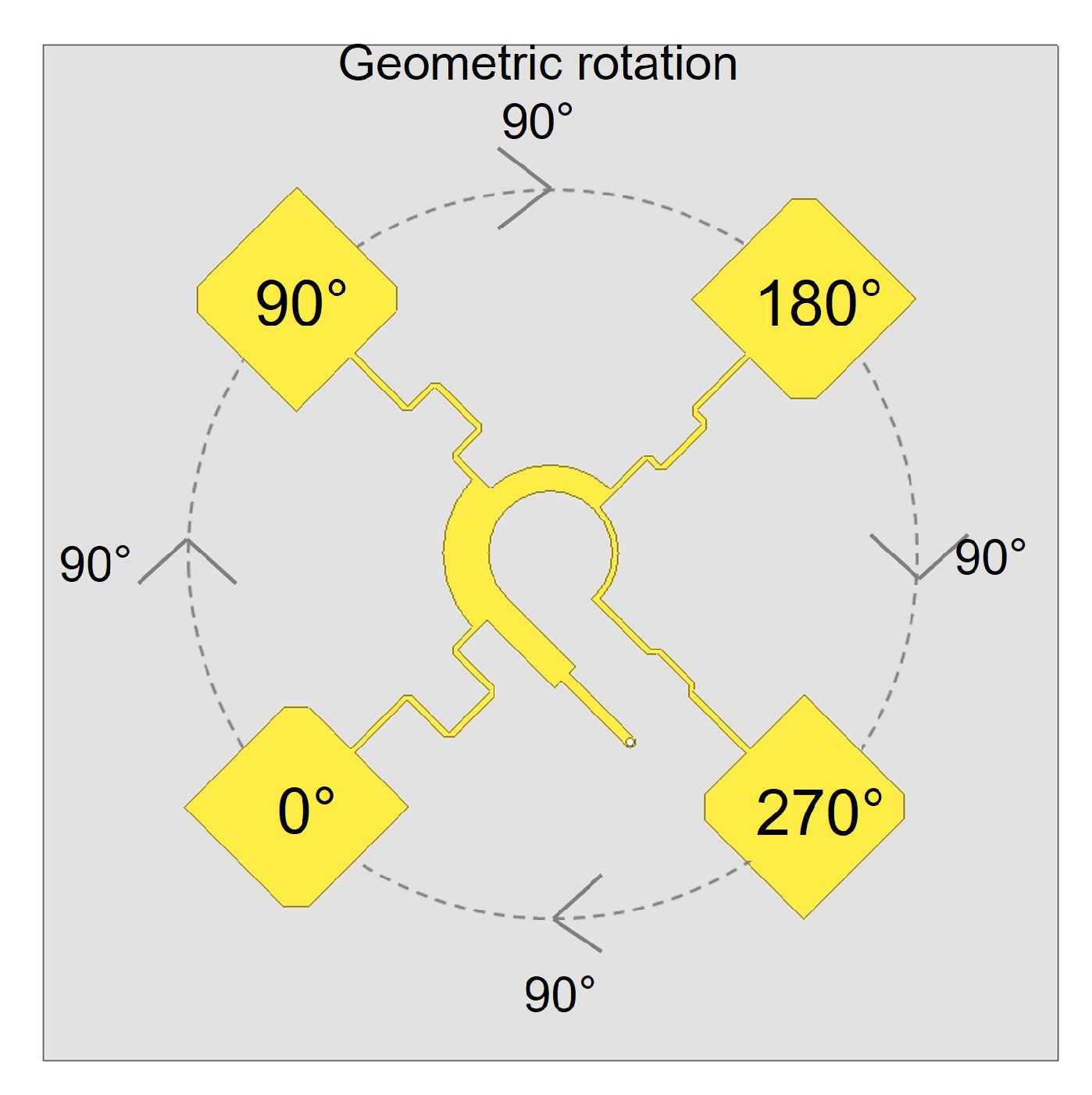
Once the design of the individual antenna element was complete, we performed three geometric rotations around a central point to form a 4-element subarray, as illustrated in Figure A2. After the rotations, the spacing between the antenna elements was approximately equal to the half-wavelength of the 5.8 GHz RF wave in the vacuum, which is 26.0 mm. The four antennas were then connected to a common ring power divider, with the four ports of the divider delivering nearly equal power outputs, and a phase difference of sequentially.
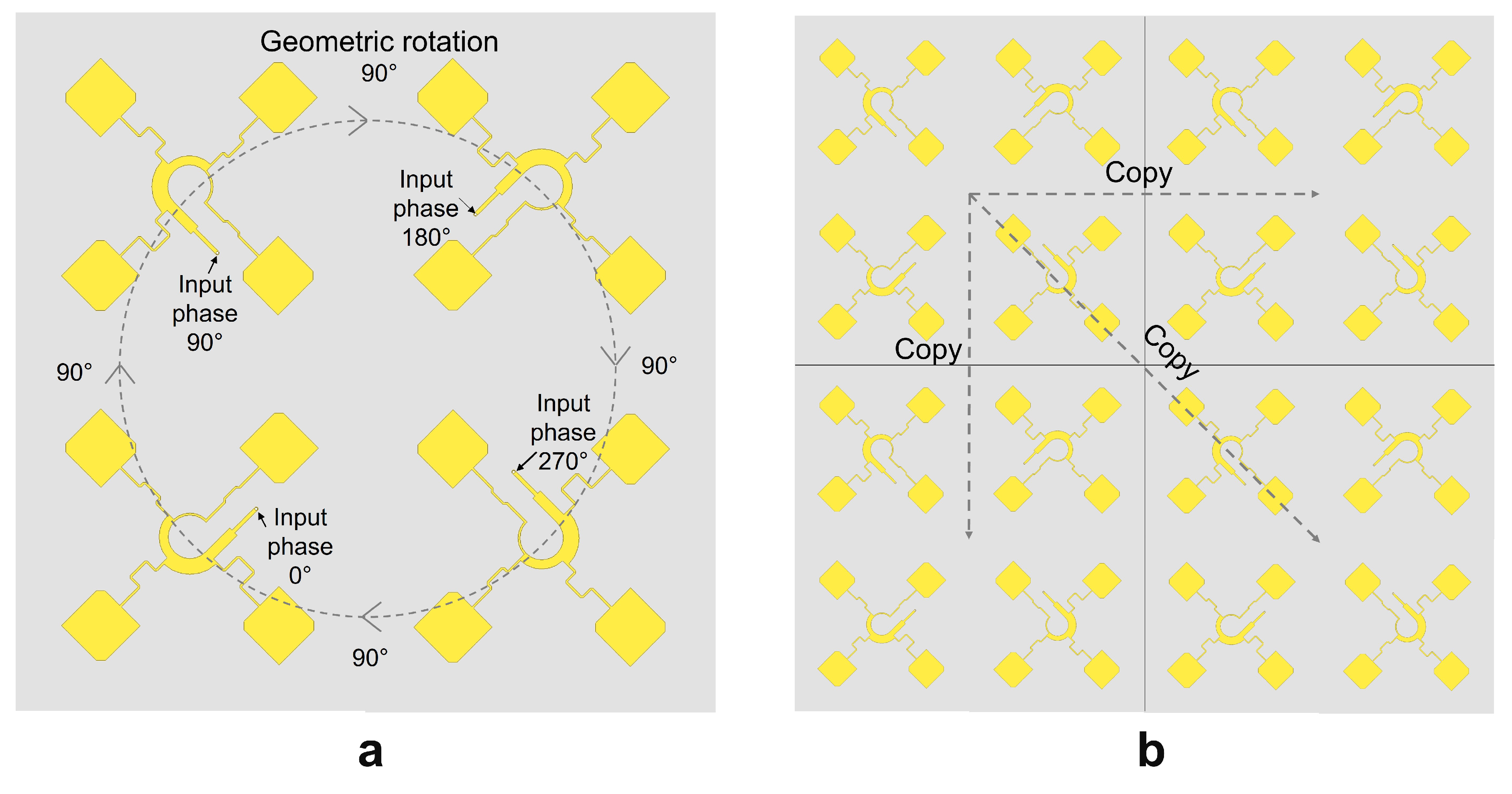
The process of generating a 16-element subarray was similar to the formation of the 4-element subarray, and the key difference was that the 4-element subarray was treated as a unit and rotated as a whole. As shown in Figure A3a, the 4-element antenna subarray was rotated three times around its vertex to form the 16-element subarray. Unlike 4-element subarray, where different feeding phases were achieved by adjusting the lengths of the microstrip transmission lines, in 16-element subarray, different feeding phases were directly controlled by the digital phase shifters in the Tx system. In both cases, the phase differences were sequentially increased by .
In the process of expanding the 16-element subarray to the 64-element Tx antenna array, the 16-element subarray was simply replicated three times without any rotation, as shown in Figure A3b. This approach not only streamlined the design process but also offered practical advantages in manufacturing. Due to the large area of the 64-element antenna array, it was challenging to manufacture it in a single process using ceramic tape casting. Therefore, the solution was to produce multiple 16-element sub-arrays and then solder them onto a metal plate to form the final Tx antenna array.
Figure A3.
Configuration of (a) the 16-element subarray and (b) the 64-element Tx antenna array
Appendix A.2. Design of the Rx Antenna Array
Due to the difficulty in controlling the phase received by each antenna at the Rx end, the Rx antenna employed a different design approach to achieve circular polarization. The detailed dimensions are shown in Figure A4. It can be observed that the design of the receiving antenna was more compact, with narrower spacing between antenna elements. This configuration aimed to achieve a higher antenna density, thereby enhancing the efficiency of energy transmission.
Figure A4.
Configuration of the Rx antenna
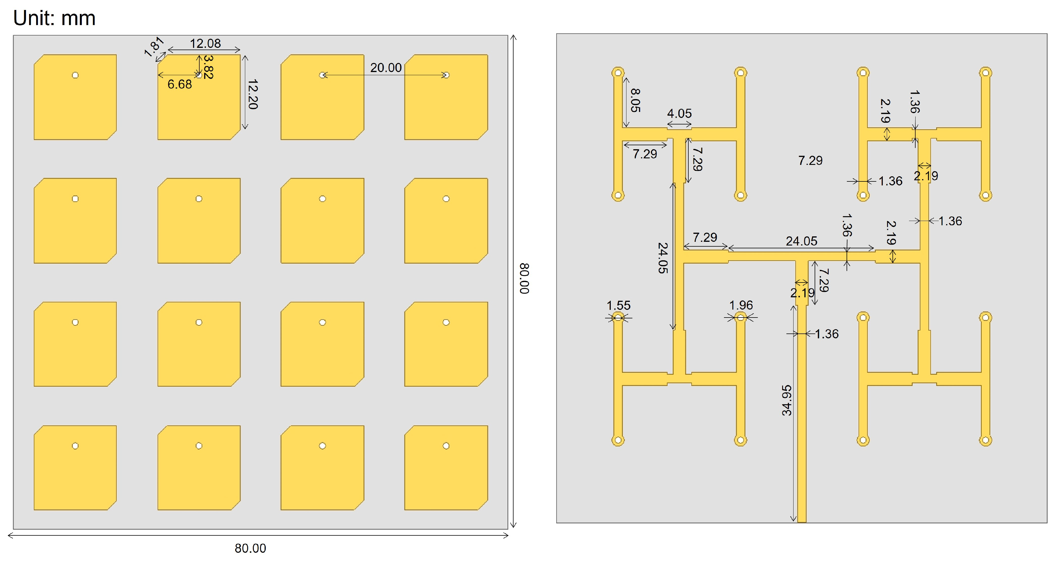
The Rx antenna array utilized a multi-layer board design, which effectively involved bonding two double-sided copper-clad substrates together using a pre-preg (PP) sheet. The top layer served as the antenna layer, while the second and third layers functioned as the dielectric layer and the GND layer for the Rx antenna, respectively. The fourth layer consisted of the PP layer, and the fifth and sixth layers served as the power divider’s GND layer and dielectric layer. The bottom layer was the signal layer of the power divider. The adjustment of the axial ratio for the Rx antenna was primarily achieved by controlling the side length, the chamfer length, and the feeding position of the patch antenna. The antenna and power divider were connected through metalized vias, and the impedance of the power divider transmission lines was optimized to ensure a low reflection loss.
Appendix A.3. Design of the Rectifier
The rectifier is a critical component in determining energy efficiency. Due to the lower breakdown voltage of GaAs Schottky diodes compared to GaN materials, we employed a parallel configuration of multiple diodes to achieve a higher power capacity. The HSMS-286L Schottky diode used in our design contains three individual diodes within a single component package. By placing one HSMS-286L on each side of the main transmission line, we effectively utilized a total of six independent Schottky diodes for rectification.
Figure A5.
Geometric dimensions of the rectifier
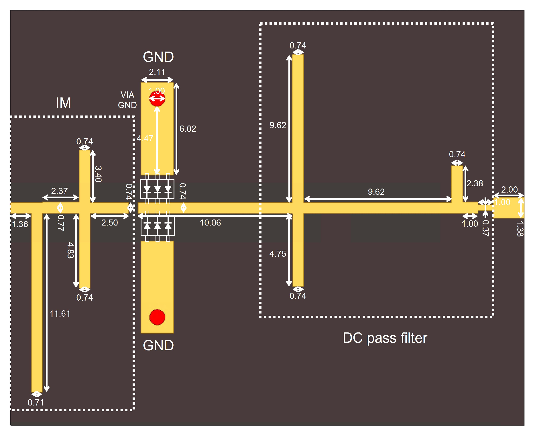
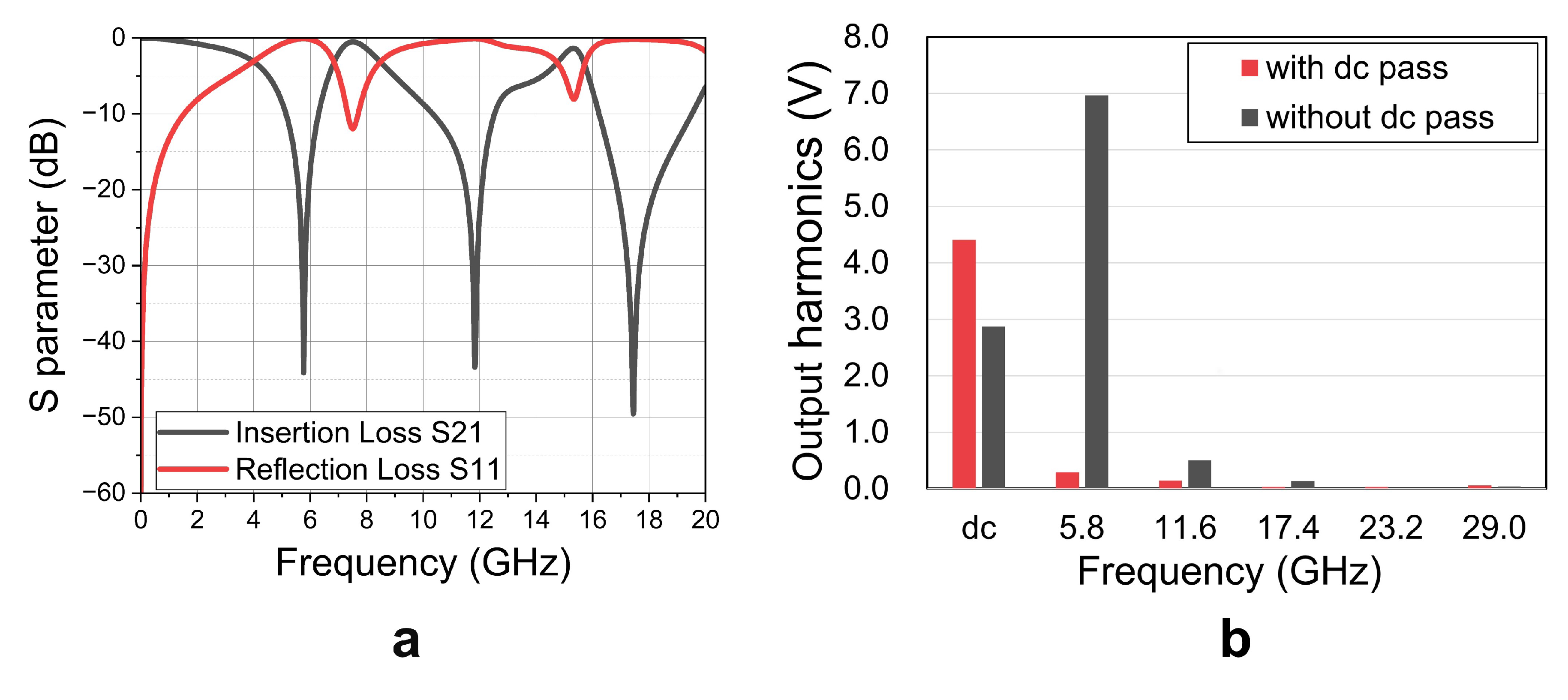
The dimensions of the rectifier are shown in Figure A5, which primarily consists of a dc pass filter, a harmonic suppression impedance matching (IM) network, transmission lines, Schottky diodes, and GND plates. The purpose of the dc pass filter is to suppress the output of RF energy and reflect the harmonics back to the Schottky diodes for re-rectification, thereby enhancing the overall system efficiency. Given that the fundamental frequency is 5.80 GHz, with significant second-order harmonics at 11.60 GHz and third-order harmonics at 17.40 GHz, the dc pass filter focused primarily on suppressing these three components. The stub lengths corresponding to these three frequencies are approximately equal to , , and of the wavelength of 5.80 GHz in the dielectric. The S-parameters of the dc pass filter are shown in Figure A6a, it can be observed that the insertion loss S21 at these three frequencies is less than -20 dB. The harmonics distribution with and without the dc pass filter before impedance matching is shown in Figure A6b. It is evident that after the addition of the dc pass filter, the RF components at the output significantly decreased, resulting in an increase in dc voltage. A transmission line was placed between the Schottky diodes and the dc pass filter to reduce reflections.
Figure A6.
Simulated results of the dc pass filter. (a) The S-parameter, and (b) the output harmonics distribution figure with and without the dc pass filter
Figure A6.
Simulated results of the dc pass filter. (a) The S-parameter, and (b) the output harmonics distribution figure with and without the dc pass filter
The impedance matching network serves two primary functions: first, it reduces the return loss at the fundamental frequency of 5.80 GHz, allowing the majority of RF energy to enter the Schottky diodes for rectification; second, it suppresses the second-order and third-order harmonics at 11.60 GHz and 17.40 GHz. This ensures that the harmonics generated by the diodes cannot pass through the input or output ports, but are confined within the rectifier for re-rectification or dissipation.
Figure A7.
Simulated (a) S-parameter of the impedance matching network, (b) impedance observed from the input port with different input power and (c) the final return loss of the rectifier with different input power
Figure A7.
Simulated (a) S-parameter of the impedance matching network, (b) impedance observed from the input port with different input power and (c) the final return loss of the rectifier with different input power
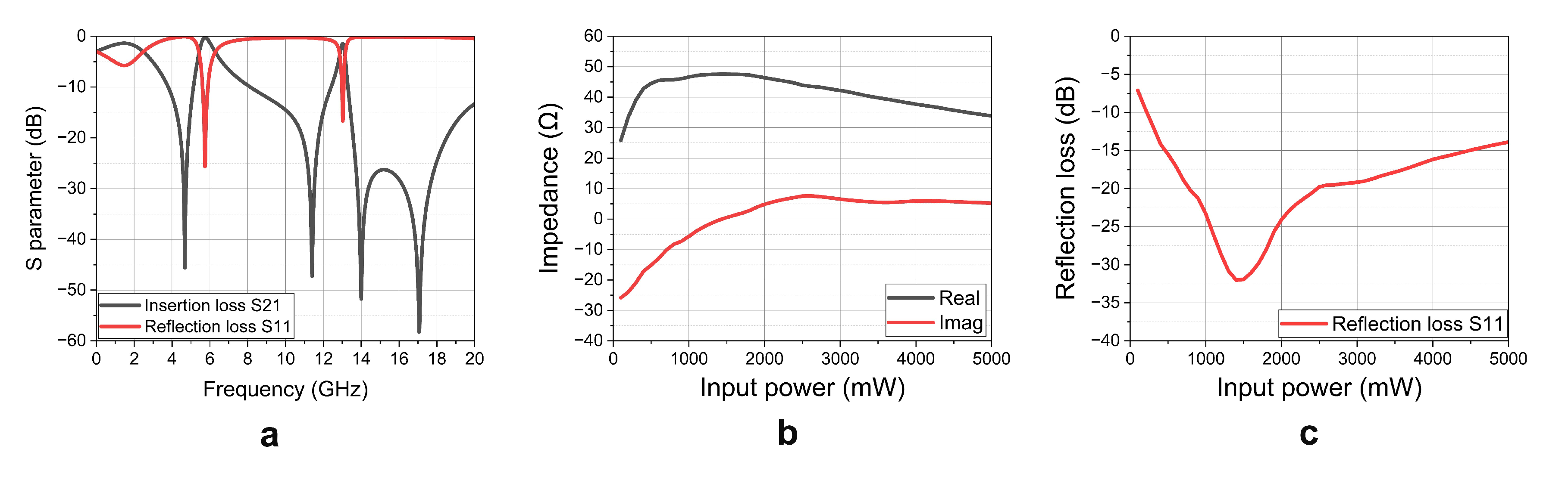
The S-parameter of the impedance matching network is shown in Figure A7a. It shows that the return loss at 5.80 GHz is S11 < -17.2 dB, indicating effective energy transfer at the fundamental frequency, while there is significant transmission loss with S21< -25.1 dB at 11.60 GHz and S21< -34.7 dB at 17.40 GHz. This confirms that the impedance matching network successfully fulfills its intended functions.
After performing impedance matching, the input impedance observed from the input port, as depicted in Figure A7b, is 44.7 + at the point of highest efficiency of 2400 mW. This value is close to the impedance of the SMA connector. Additionally, the reflection loss S11 was simulated to assess the performance of the proposed rectifier, as shown in Figure A7c. The results indicate that the insertion loss remains below -15 dB as the input power ranges from 500 mW to 4500 mW, demonstrating that the rectifier maintains good matching performance across a broad power range.
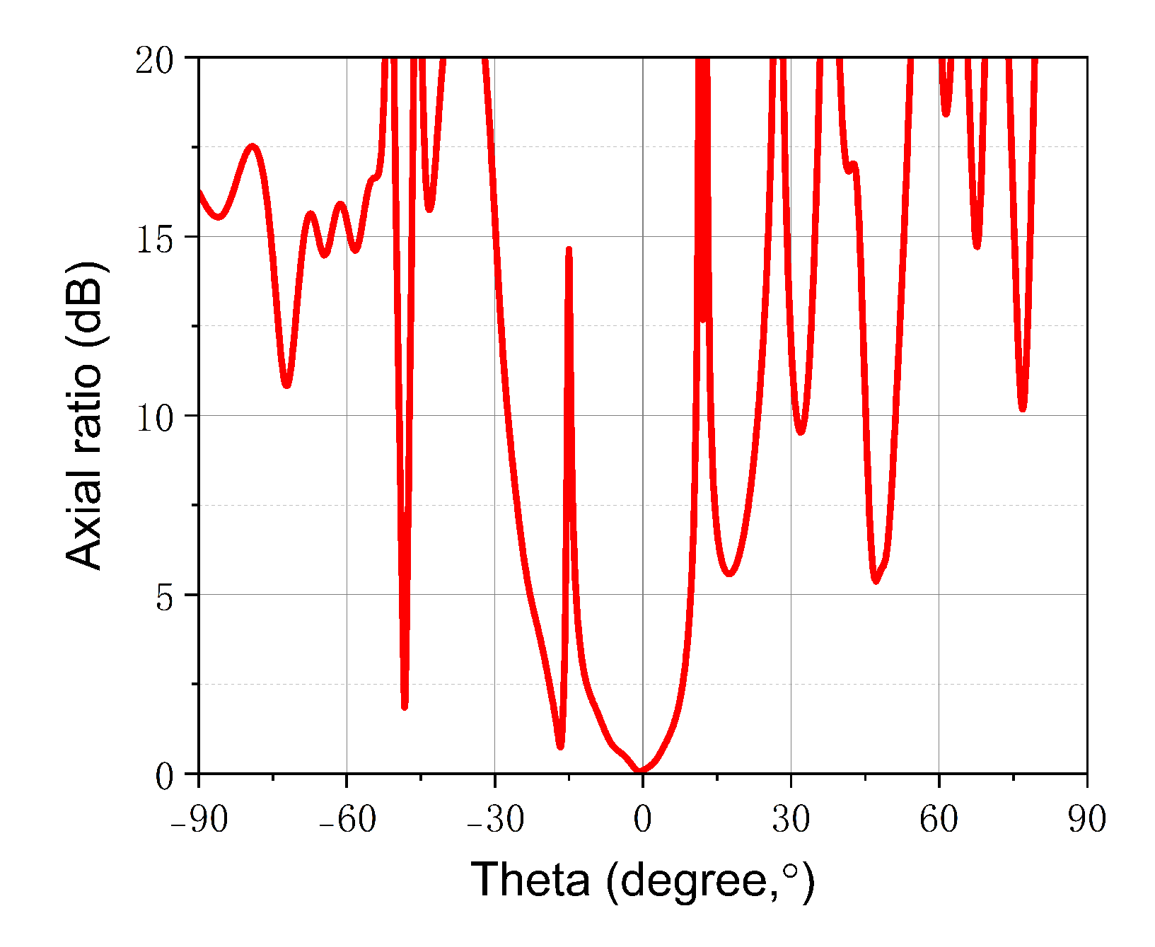
Appendix A.4. Measurement of the Axial Ratio of the Tx Antenna Array
The sequentially rotated ultra-low axial ratio antenna array is employed in the Tx end to get nearly perfect circularly polarized RF waves. In order to demonstrate the performance of the proposed design, we have measured the axial ratio of the Tx antenna array in the microwave anechoic chamber. The results are shown in Figure A8,it can be observed that the Tx axial ratio is near to zero at the center position, means that the RF wave are nearly perfect circularly polarized.
Figure A8.
Measured axial ratio of the Tx antenna array
References
- Wang, M.; Tan, Q.; Yu, J.; Xia, D.; Zhang, W.; Zhang, C.C.; Zhang, Z.; Wang, J.; Liu, K.; Li, J. Pollution-free recycling of lead and sulfur from spent lead-acid batteries via a facile vacuum roasting route. Green Energy and Resources 2023, 1, 100002. [Google Scholar] [CrossRef]
- Song, M.; Jayathurathnage, P.; Zanganeh, E.; Krasikova, M.; Smirnov, P.; Belov, P.; Kapitanova, P.; Simovski, C.; Tretyakov, S.; Krasnok, A. Wireless power transfer based on novel physical concepts. Nature Electronics 2021, 4, 707–716. [Google Scholar] [CrossRef]
- Li, W.; Yu, Q.; Qiu, J.H.; Qi, J. Intelligent wireless power transfer via a 2-bit compact reconfigurable transmissive-metasurface-based router. Nature Communications 2024, 15, 2807. [Google Scholar] [CrossRef] [PubMed]
- Xia, D.X.; Han, J.Q.; Mu, Y.J.; Guan, L.; Wang, X.; Ma, X.J.; Zhu, L.H.; Lv, T.G.; Liu, H.X.; Shi, Y.; et al. Adaptive wireless-powered network based on CNN near-field positioning by a dual-band metasurface. Nature Communications 2024, 15, 1–11. [Google Scholar] [CrossRef]
- Brown, W.C. The history of power transmission by radio waves. IEEE Transactions on microwave theory and techniques 1984, 32, 1230–1242. [Google Scholar] [CrossRef]
- Rodenbeck, C.T.; Jaffe, P.I.; Strassner II, B.H.; Hausgen, P.E.; McSpadden, J.O.; Kazemi, H.; Shinohara, N.; Tierney, B.B.; DePuma, C.B.; Self, A.P. Microwave and millimeter wave power beaming. IEEE journal of microwaves 2021, 1, 229–259. [Google Scholar] [CrossRef]
- Du, Z.X.; Zhang, X.Y. High-efficiency microwave rectifier with less sensitivity to input power variation. IEEE Microwave and Wireless Components Letters 2017, 27, 1001–1003. [Google Scholar] [CrossRef]
- Du, Z.X.; Zhang, X.Y. High-efficiency single-and dual-band rectifiers using a complex impedance compression network for wireless power transfer. IEEE Transactions on industrial electronics 2017, 65, 5012–5022. [Google Scholar] [CrossRef]
- Huang, M.; Lin, Y.L.; Ou, J.H.; yin Zhang, X.; Lin, Q.W.; Che, W.; Xue, Q. Single-and dual-band RF rectifiers with extended input power range using automatic impedance transforming. IEEE Transactions on Microwave Theory and Techniques 2019, 67, 1974–1984. [Google Scholar] [CrossRef]
- Liu, C.; Lin, H.; He, Z.; Chen, Z. Compact patch rectennas without impedance matching network for wireless power transmission. IEEE Transactions on Microwave Theory and Techniques 2022, 70, 2882–2890. [Google Scholar] [CrossRef]
- Xiao, H.; Zhang, H.; Song, W.; Wang, J.; Chen, W.; Lu, M. A high-input power rectifier circuit for 2.45-GHz microwave wireless power transmission. IEEE Transactions on Industrial Electronics 2021, 69, 2896–2903. [Google Scholar] [CrossRef]
- Yang, Y.; Li, J.; Li, L.; Liu, Y.; Zhang, B.; Zhu, H.; Huang, K. A 5.8 GHz circularly polarized rectenna with harmonic suppression and rectenna array for wireless power transfer. IEEE Antennas and Wireless propagation letters 2018, 17, 1276–1280. [Google Scholar] [CrossRef]
- Dang, K.; Zhang, J.; Zhou, H.; Huang, S.; Zhang, T.; Bian, Z.; Zhang, Y.; Wang, X.; Zhao, S.; Wei, K.; et al. A 5.8-GHz high-power and high-efficiency rectifier circuit with lateral GaN Schottky diode for wireless power transfer. IEEE Transactions on Power Electronics 2019, 35, 2247–2252. [Google Scholar] [CrossRef]
- Dang, K.; Zhang, J.; Zhou, H.; Yin, S.; Zhang, T.; Ning, J.; Zhang, Y.; Bian, Z.; Chen, J.; Duan, X.; et al. Lateral GaN Schottky barrier diode for wireless high-power transfer application with high RF/DC conversion efficiency: From circuit construction and device technologies to system demonstration. IEEE Transactions on Industrial Electronics 2019, 67, 6597–6606. [Google Scholar] [CrossRef]
- Joseph, S.D.; Hsu, S.S.; Alieldin, A.; Song, C.; Liu, Y.; Huang, Y. High-power wire bonded GaN rectifier for wireless power transmission. IEEE Access 2020, 8, 82035–82041. [Google Scholar] [CrossRef]
- Li, Y.; Pu, T.F.; Li, X.B.; Zhong, Y.R.; Yang, L.A.; Fujiwara, S.; Kitahata, H.; Ao, J.P. GaN Schottky barrier diode-based wideband and medium-power microwave rectifier for wireless power transmission. IEEE Transactions on Electron Devices 2020, 67, 4123–4129. [Google Scholar] [CrossRef]
- Wang, Y.; Wei, G.; Dong, S.; Dong, Y.; Yu, X.; Li, X. A high-efficiency self-synchronous rf–dc rectifier based on time-reversal duality for wireless power transfer applications. Electronics 2021, 11, 90. [Google Scholar] [CrossRef]
- You, F.; Dong, S.; Wang, Y.; Yu, X.; Li, C. Design method of self-driving RF-DC rectifier based on waveform-guided solutions to passive matching network. IEEE Transactions on Power Electronics 2018, 34, 6498–6509. [Google Scholar] [CrossRef]
- You, F.; Dong, S.W.; Wang, Y.; Zhang, S.; Yu, X.; He, S. Design of a self-driving transistor-based RF-DC converter based on optimized harmonic-tuned rectification waveforms. IEEE Transactions on Microwave Theory and Techniques 2020, 68, 4433–4444. [Google Scholar] [CrossRef]
- Zhang, Z.; Fusco, V.; Cheng, Z.; Buchanan, N.; Gu, C. A Transistor-Based Dual-Band High-Efficiency Rectifier With Dual-Polarity Modes. IEEE Microwave and Wireless Components Letters 2021, 32, 169–172. [Google Scholar] [CrossRef]
- Belo, D.; Ribeiro, D.C.; Pinho, P.; Carvalho, N.B. A selective, tracking, and power adaptive far-field wireless power transfer system. IEEE Transactions on Microwave Theory and Techniques 2019, 67, 3856–3866. [Google Scholar] [CrossRef]
- Hu, L.; Ma, X.; Yang, G.; Zhang, Q.; Zhao, D.; Cao, W.; Wang, B.Z. Auto-tracking time reversal wireless power transfer system with a low-profile planar RF-channel cascaded transmitter. IEEE Transactions on Industrial Electronics 2022, 70, 4245–4255. [Google Scholar] [CrossRef]
- Koo, H.; Bae, J.; Choi, W.; Oh, H.; Lim, H.; Lee, J.; Song, C.; Lee, K.; Hwang, K.; Yang, Y. Retroreflective transceiver array using a novel calibration method based on optimum phase searching. IEEE Transactions on Industrial Electronics 2020, 68, 2510–2520. [Google Scholar] [CrossRef]
- Park, I.; Lee, E.; Ku, H. Angle tracking automatic beamforming for microwave power transfer systems. In Proceedings of the 2020 IEEE Wireless Power Transfer Conference (WPTC). IEEE, 2020, pp. 16–18.
- Rotenberg, S.A.; Podilchak, S.K.; Re, P.D.H.; Mateo-Segura, C.; Goussetis, G.; Lee, J. Efficient rectifier for wireless power transmission systems. IEEE Transactions on Microwave Theory and Techniques 2020, 68, 1921–1932. [Google Scholar] [CrossRef]
- Yang, B.; Mitani, T.; Shinohara, N. Auto-Tracking Wireless Power Transfer System With Focused-Beam Phased Array. IEEE Transactions on Microwave Theory and Techniques 2022.
- Mohammadi-Asl, S.; Nourinia, J.; Ghobadi, C.; Majidzadeh, M. Wideband compact circularly polarized sequentially rotated array antenna with sequential-phase feed network. IEEE Antennas and Wireless Propagation Letters 2017, 16, 3176–3179. [Google Scholar] [CrossRef]
- Xu, J.; Hong, W.; Jiang, Z.H.; Zhang, H.; Wu, K. Low-profile wideband vertically folded slotted circular patch array for Ka-band applications. IEEE Transactions on Antennas and Propagation 2020, 68, 6844–6849. [Google Scholar] [CrossRef]
- Yan, N.; Ma, K.; Luo, Y. An SISL sequentially rotated feeding circularly polarized stacked patch antenna array. IEEE transactions on antennas and propagation 2019, 68, 2060–2067. [Google Scholar] [CrossRef]
- Zhu, X.; Lyu, S.; Wang, X.; Zhao, Q. TPH-YOLOv5: Improved YOLOv5 based on transformer prediction head for object detection on drone-captured scenarios. In Proceedings of the Proceedings of the IEEE/CVF international conference on computer vision, 2021, pp. 2778–2788.
- Jocher, G.; Chaurasia, A.; Stoken, A.; Borovec, J.; Kwon, Y.; Michael, K.; Fang, J.; Yifu, Z.; Wong, C.; Montes, D.; et al. ultralytics/yolov5: v7. 0-yolov5 sota realtime instance segmentation. Zenodo 2022.
- Rezatofighi, H.; Tsoi, N.; Gwak, J.; Sadeghian, A.; Reid, I.; Savarese, S. Generalized intersection over union: A metric and a loss for bounding box regression. In Proceedings of the Proceedings of the IEEE/CVF conference on computer vision and pattern recognition, 2019, pp. 658–666.
- Liu, L.; Yu, M.; Shao, L. Unsupervised local feature hashing for image similarity search. IEEE transactions on cybernetics 2015, 46, 2548–2558. [Google Scholar] [CrossRef]
- Park, J.H.; Tran, N.M.; Hwang, S.I.; Kim, D.I.; Choi, K.W. Design and implementation of 5.8 GHz RF wireless power transfer system. IEEE Access 2021, 9, 168520–168534. [Google Scholar] [CrossRef]
Figure 1.
The proposed RF WPT system in smart living scenarios

Figure 2.
Intelligent RF WPT System Overview.
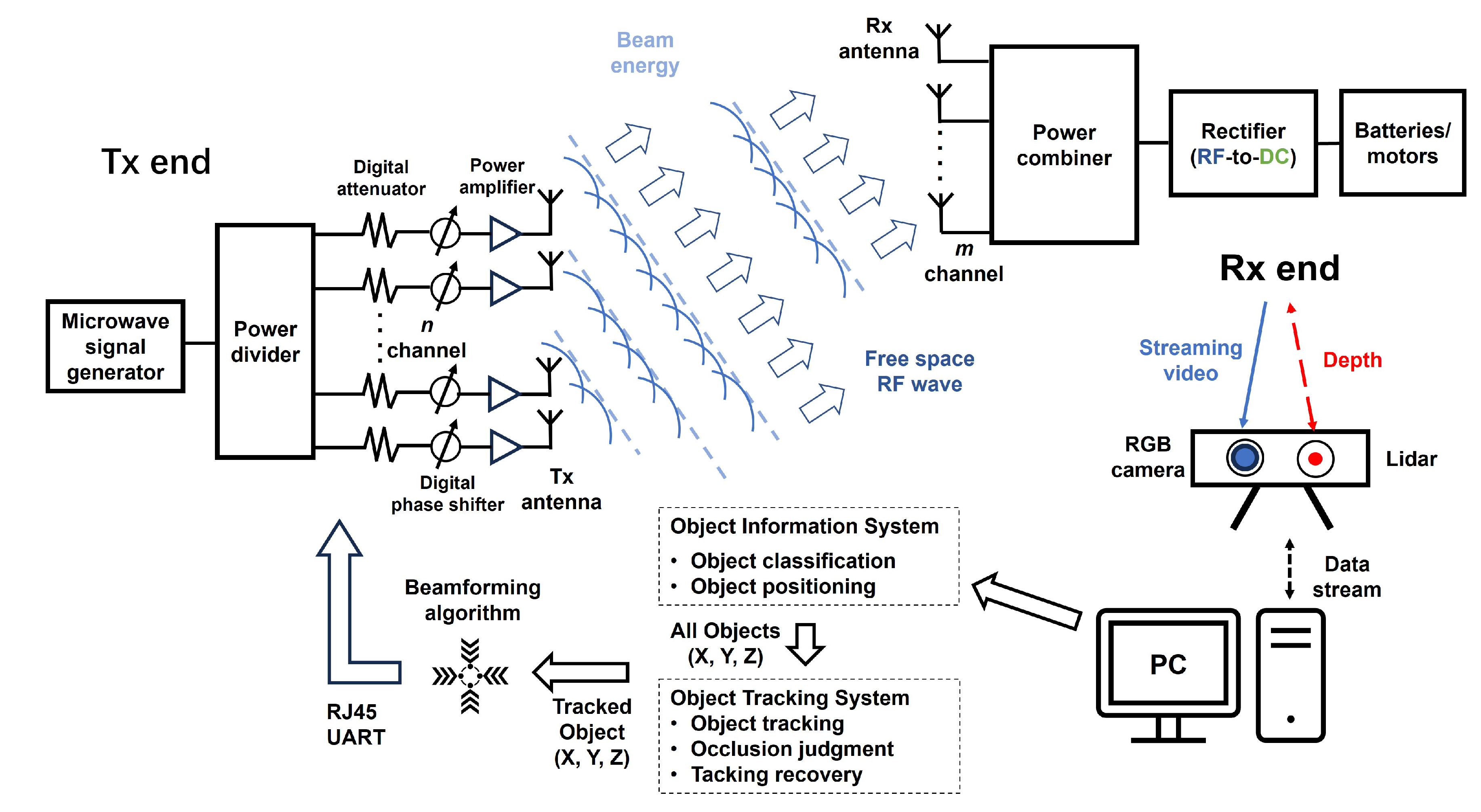
Figure 3.
Configuration of the Tx antenna from (a) top view and (b) rear view, the Rx antenna from (c) top view and (d) rear view. The return loss (e),(g) and normalized gain (f),(h) of the Tx and Rx antenna, respectively.
Figure 3.
Configuration of the Tx antenna from (a) top view and (b) rear view, the Rx antenna from (c) top view and (d) rear view. The return loss (e),(g) and normalized gain (f),(h) of the Tx and Rx antenna, respectively.
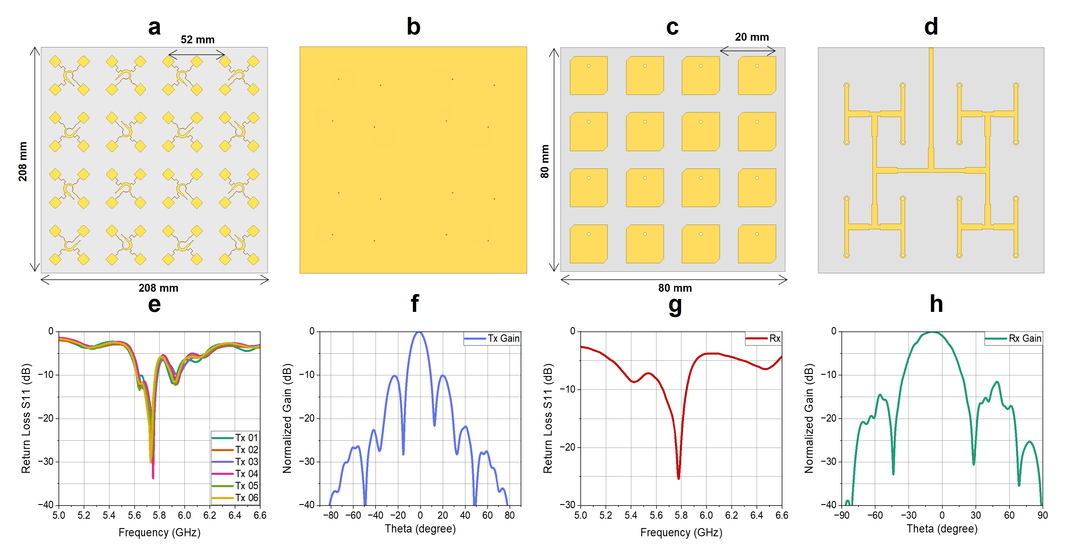
Figure 4.
(a) The principle diagram of the spatial projection algorithm. (b) Configuration of the rectifier, (c) photography of the manufactured rectifier circuit and (d) measured and simulated rectification efficiency of the rectifier.
Figure 4.
(a) The principle diagram of the spatial projection algorithm. (b) Configuration of the rectifier, (c) photography of the manufactured rectifier circuit and (d) measured and simulated rectification efficiency of the rectifier.
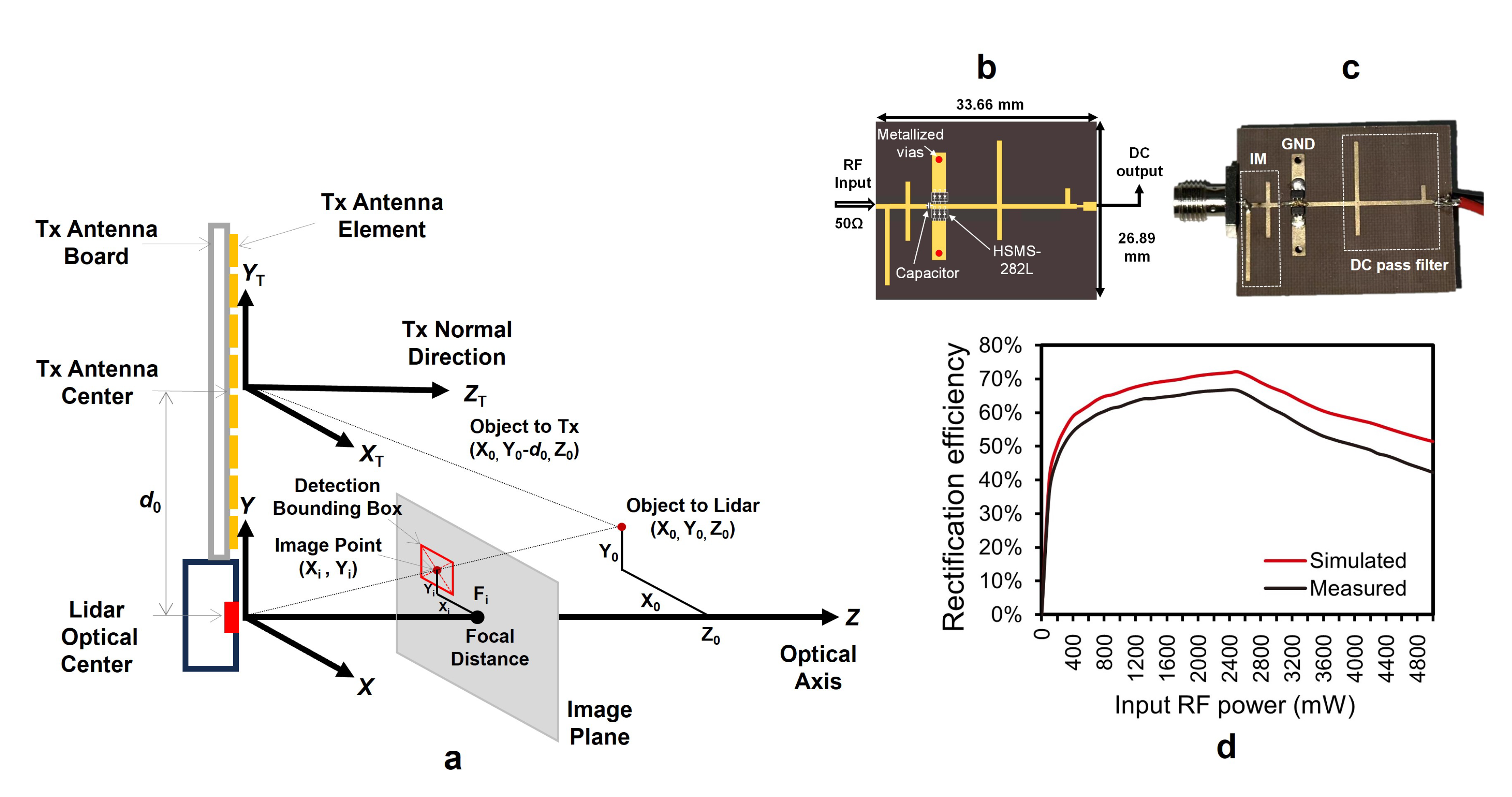
Figure 5.
The schematic diagram and flowchart of RF WPT intelligent algorithms and their subsystems.
Figure 5.
The schematic diagram and flowchart of RF WPT intelligent algorithms and their subsystems.
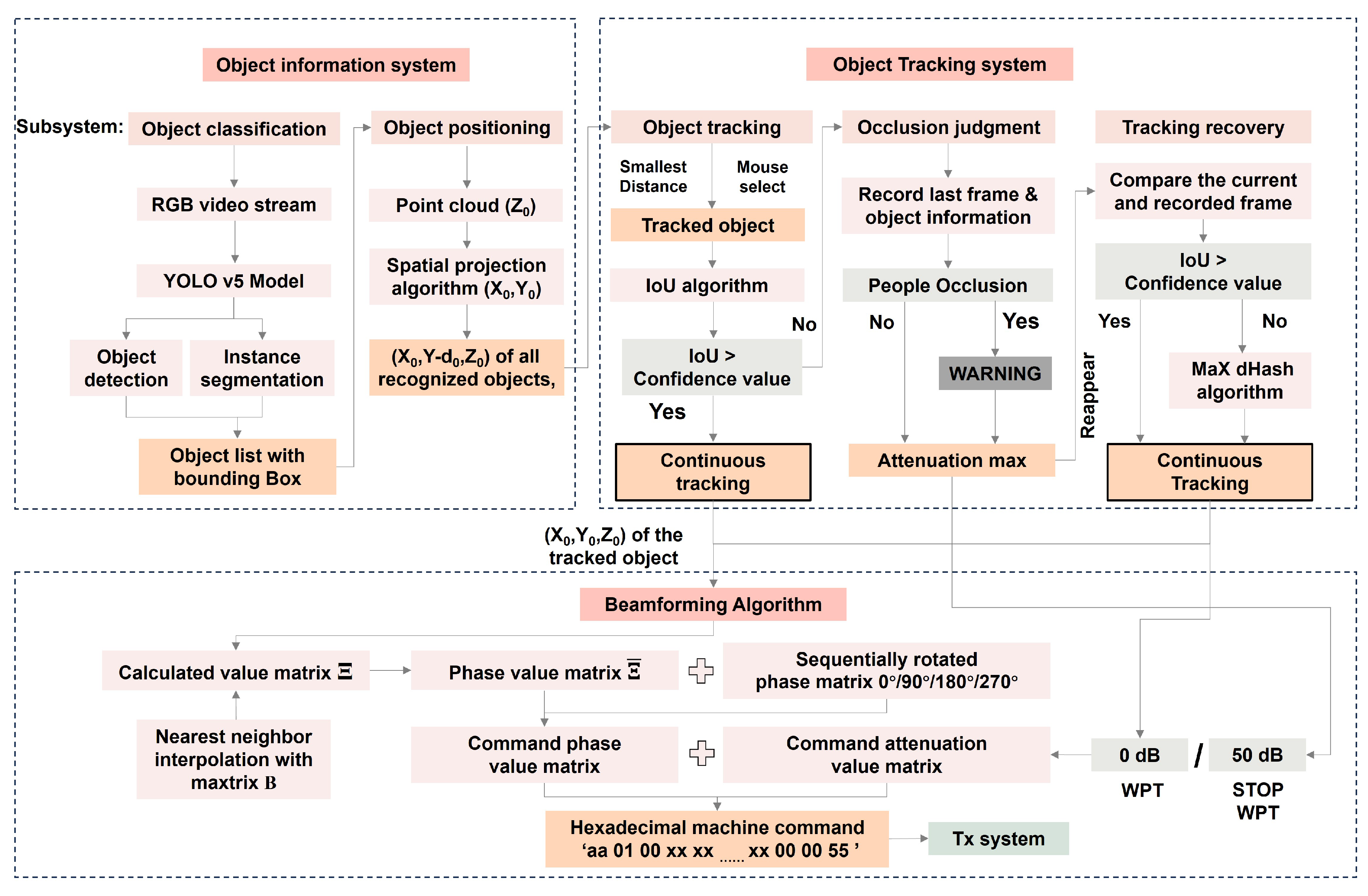
Figure 6.
Photos of the Tx system from (a) front view and (b) back view, the (c) Rx system, the Tx antenna array from (d) top view and (e) rear view. (f) Experiment of the RF WPT system in the microwave anechoic chamber, and (g) measured output dc power of the Rx system with respect to the distance from the Tx system at different angles.
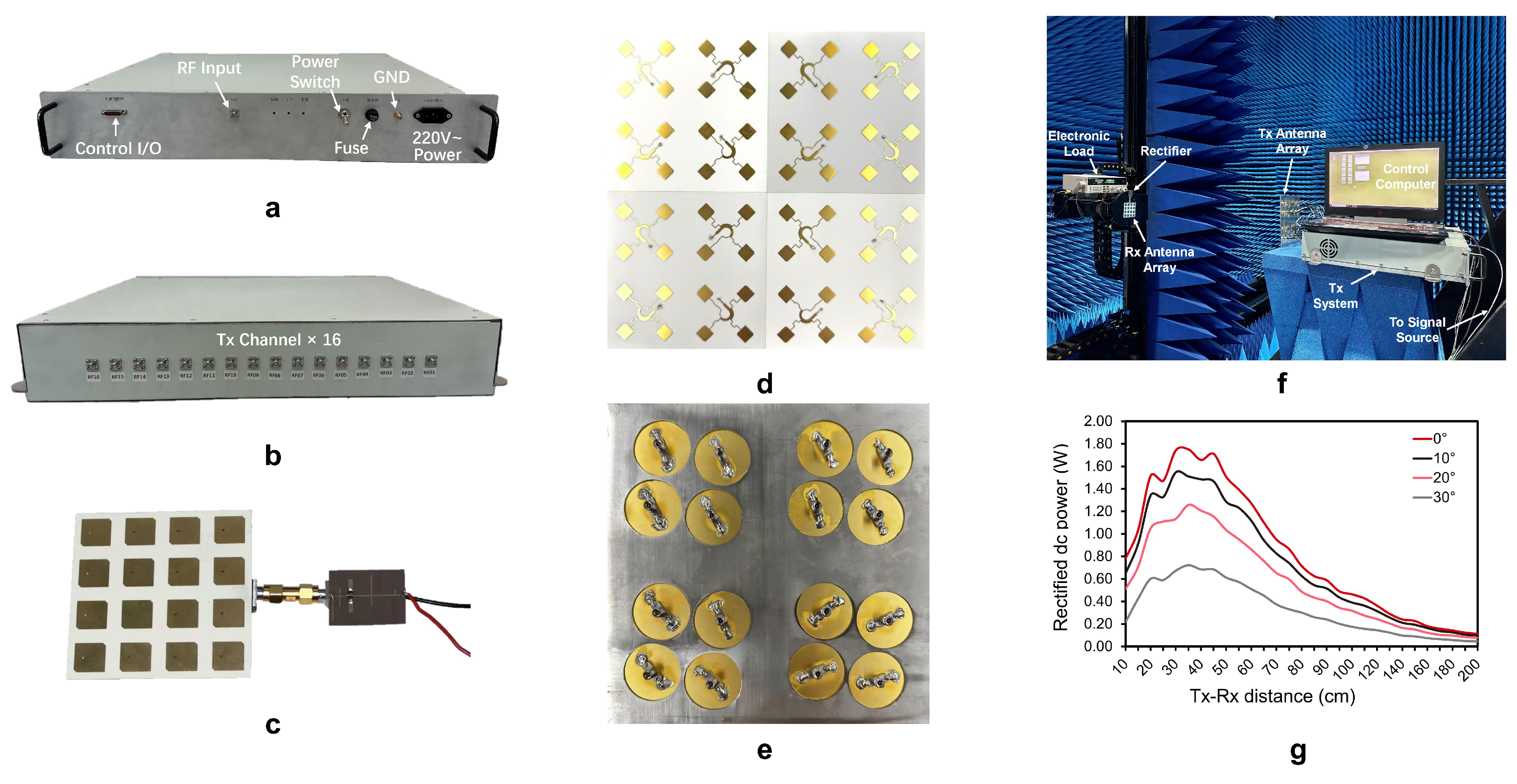
Figure 7.
Measured 2-D far-field radiation pattern of the Tx antenna array when the beam angle was (a) , (b) , (c) , (d) , (e) , (f) , (g) , (h) , (i) , (j) , (k) and (l) .
Figure 7.
Measured 2-D far-field radiation pattern of the Tx antenna array when the beam angle was (a) , (b) , (c) , (d) , (e) , (f) , (g) , (h) , (i) , (j) , (k) and (l) .
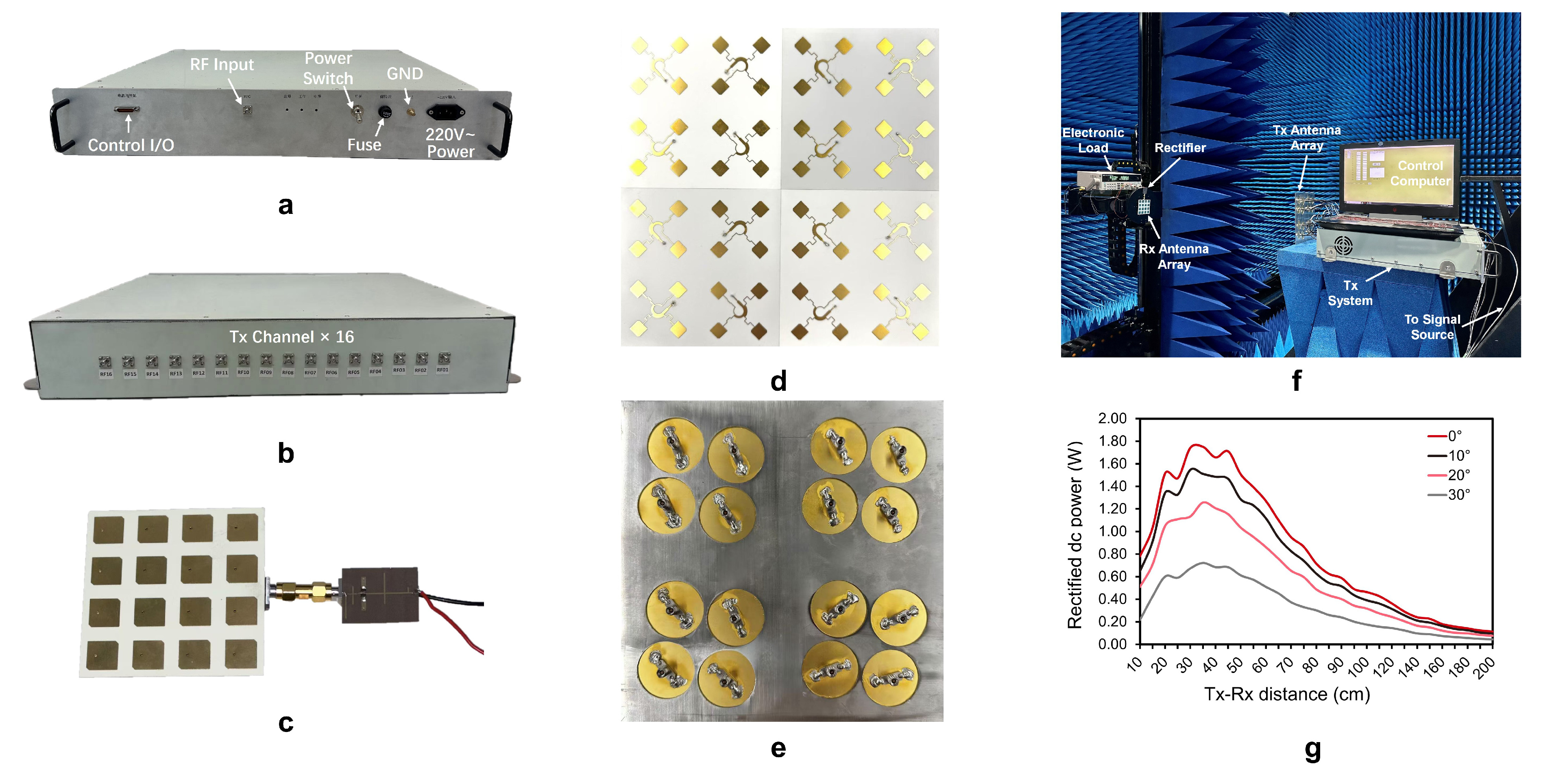
Figure 8.
UI Display of the intelligent algorithm system: (a) Upon software launch, information of all objects was displayed on the RGB video stream. (b) Selecting the cell phone as the tracked object, the phone’s information and image were displayed in the colored area, while phase and command codes were shown in the black area. (c) When the cell phone was moved, both the phase and command codes changed. (d) When the bounding boxes of the person and the cell phone overlapped but no occlusion occurred, the system continued to operate normally. (e) After placing the cell phone on the left side, the phase and command changed. (f) The moment the human body obstructed the view of the cell phone, the system immediately stopped working and issued an alert in the red area. (g) When there was no obstruction by the human body, the system continued to track the cell phone as the target and resumed normal operation. (h) When the cell phone was removed, the target moved significantly until the target was lost and the system stopped working. (i) Upon putting back the cell phone, the system immediately resumed normal tracking.
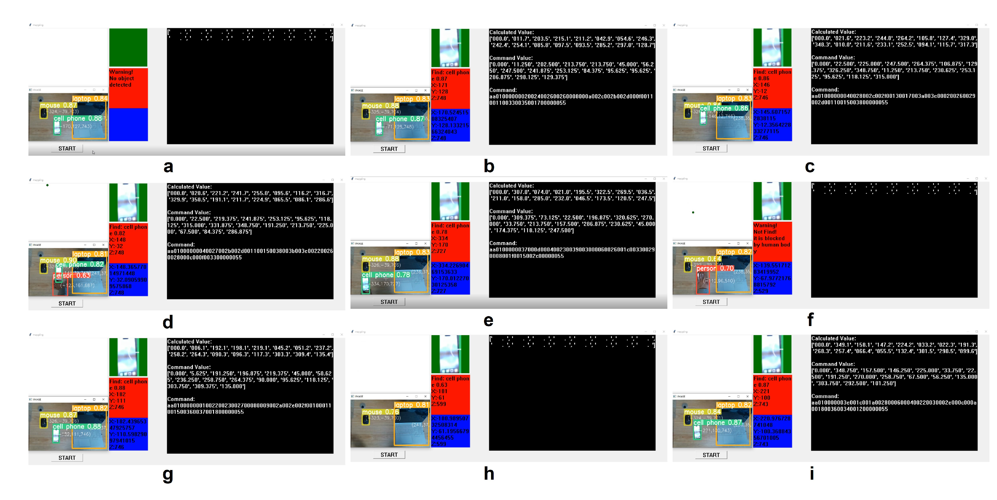
Figure 9.
The battery-free vehicle WPT demonstration platform and UI interface. (a) Successful Rx antenna recognition, awaiting mouse click to initiate RF WPT. (b) After selecting the Rx antenna, all relevant information was displayed on the UI, and the vehicle commenced movement. The vehicle subsequently moved to (c) the 9 o’clock position, (d) the 12 o’clock position, (e) the 3 o’clock position, and (f) the 6 o’clock position, maintaining stable operation throughout.
Disclaimer/Publisher’s Note: The statements, opinions and data contained in all publications are solely those of the individual author(s) and contributor(s) and not of MDPI and/or the editor(s). MDPI and/or the editor(s) disclaim responsibility for any injury to people or property resulting from any ideas, methods, instructions or products referred to in the content. |
© 2025 by the authors. Licensee MDPI, Basel, Switzerland. This article is an open access article distributed under the terms and conditions of the Creative Commons Attribution (CC BY) license (http://creativecommons.org/licenses/by/4.0/).
Copyright: This open access article is published under a Creative Commons CC BY 4.0 license, which permit the free download, distribution, and reuse, provided that the author and preprint are cited in any reuse.


