
Submitted:
11 February 2025
Posted:
11 February 2025
You are already at the latest version
Abstract
In the EU funded BRAVA project, technologies for a Fuel Cell based Power Generation System for aviation are being developed. In this paper, the test results for a demonstrator for a novel two-phase pumped cooling system with 20 kW cooling capacity are presented. This system uses the evaporation of a liquid to remove waste heat from the heat sources. Several concepts have been tested with this demonstrator, including the ‘no accumulator’ concept, which offers a large mass reduction compared to conventional cooling systems. Also, the system can be rotated, and the influence of the orientation has been tested.
Keywords:
Two-phase
; cooling
; pump
; methanol
; fuel cell
; accumulator
1. Introduction
In the EU funded BRAVA (Breakthrough Fuel Cell Technologies for Aviation) project, breakthrough technologies for a Fuel Cell based Power Generation System for aviation are being developed for aircraft capable of carrying up to 100 passengers on distances of up to 1,000 nautical miles. One of these technologies is the cooling system for the fuel cells. In another study [1], it was shown by analysis that a two-phase pumped cooling system using methanol as coolant can have a much lower mass than a conventional liquid ethylene glycol water cooling system. The mass benefit is especially large when a novel ‘no accumulator’ concept is used. In order to investigate the feasibility of this concept, a test setup with 20 kW cooling capacity was built. The test results of this setup are described in this paper.
2. Description of the Setup
Figure 1 shows a schematic drawing of the 20 kW two-phase cooling (2-PC) system. A pump transports liquid to the evaporators. In the evaporators, the heat from the heat source is absorbed and the liquid (partly) turns into vapour (i.e. the term ‘two-phase’ refers to the phase transition of the fluid from liquid to vapour). The vapour/liquid mixture then flows to the condensers. In the condensers, the absorbed heat is transferred to the air that flows through the air heat exchangers, and the vapour is turned back into liquid. The saturation temperature in the system depends on the pressure, and this pressure is controlled by the accumulator. Most 2-PC have a Heat Controlled Accumulator (HCA) [2,3,4,5]. In a HCA, both vapour and liquid are present and the saturation temperature in the system is controlled by a heater on the vessel. The main advantage of a HCA is that it is relatively simple. Disadvantages of a HCA are the energy consumption of the heater, and the sensitivity to the direction of acceleration. However, it is also possible to use a Pressure Controlled Accumulator (PCA). In a PCA, only subcooled liquid and no vapour is present and the pressure of the liquid in the accumulator can be controlled with pressurized air or N2 gas which is separated from the liquid by a bellows, bladder, or diaphragm. The 20 kW system uses a 5 litres Varem expansion vessel (which is also used in residential heating systems) with an EPDM bladder. Figure 2 to figure 4 show CAD drawings and figure 5 shows photos. The system has 16 parallel evaporator plates divided over 2 parallel branches. The heat load of 20 kW is generated by foil heaters attached to the evaporator plates. The system has 4 air heat exchangers in a parallel configuration. A fan is used to force air through the heat exchangers. The airflow through the heat exchangers can be (partly) blocked by inserting a plate between the air duct and the heat exchangers, see figure 4. The system has two flow meters. The difference between the measured flow of these flow meters can be used to derive the methanol flow into and out of the accumulator. The system also has a motorized control valve to bypass the condenser. The setup has 4 viewing glasses with cameras to monitor the flow pattern and presence of gas bubbles at several locations. With this setup, the following will be tested:
- Saturation temperature control with a PCA.
- Influence of orientation by rotating the system.
- Different methods to control evaporator inlet temperature.
- Influence of blocked airflow through a condenser.
- Testing of the ‘no accumulator’ concept. For this, the system is equipped with a valve between the accumulator and the loop.
Figure 1.
Schematic drawing of the 20 kW test setup.
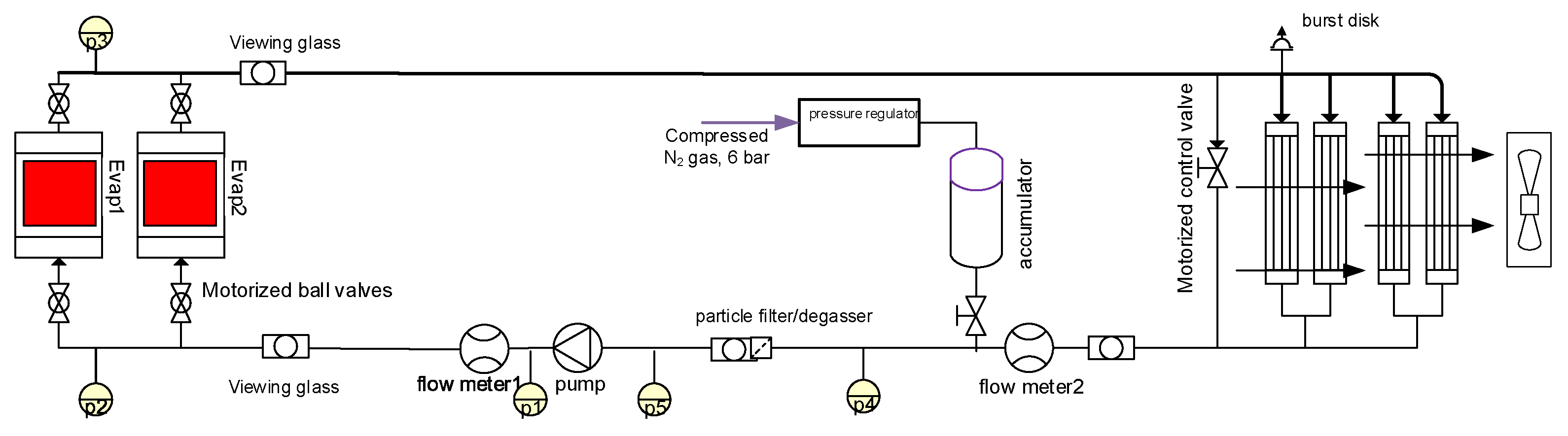
Figure 2.
CAD drawing of the 20 kW test setup.
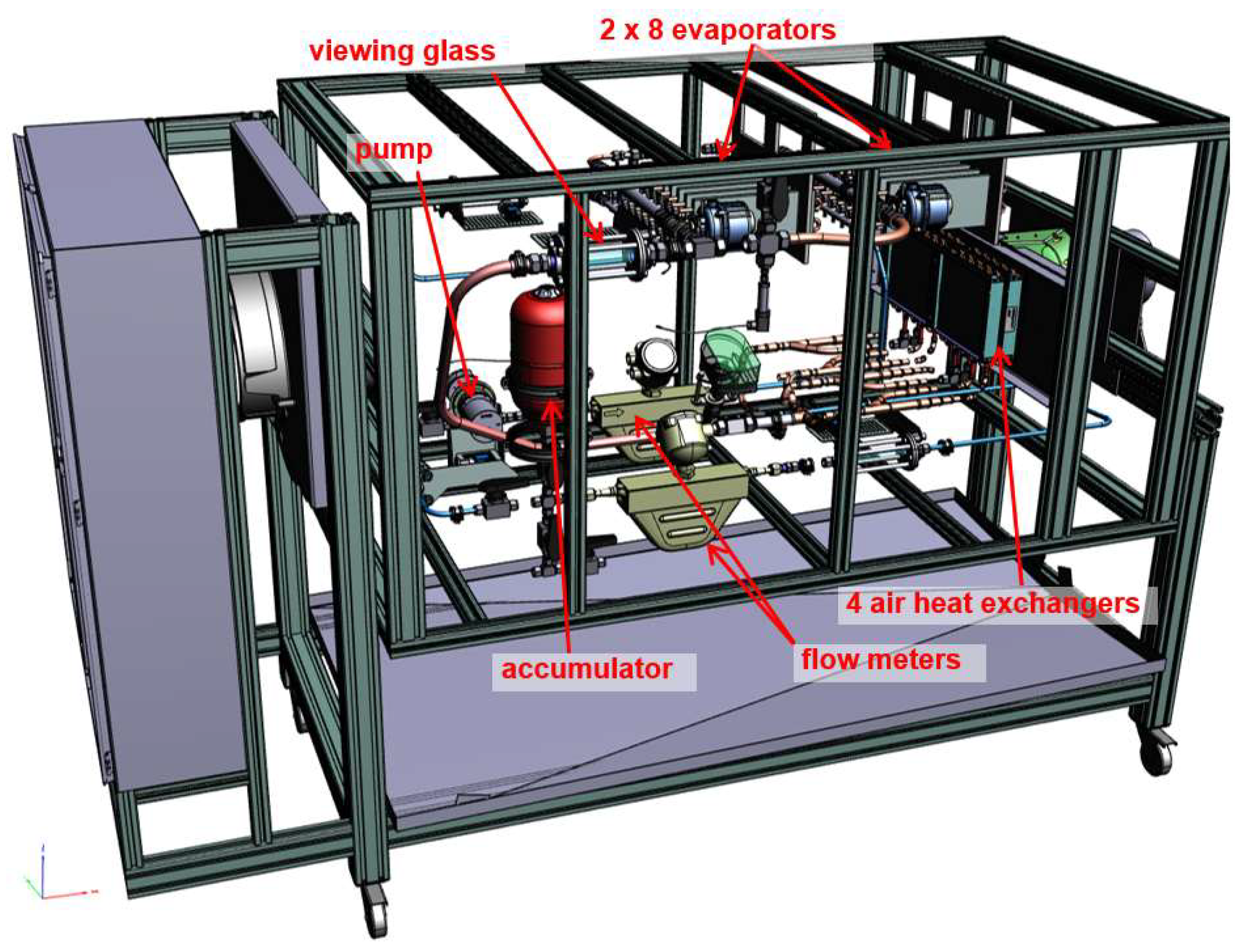
Figure 3.
CAD drawing of the evaporator section.
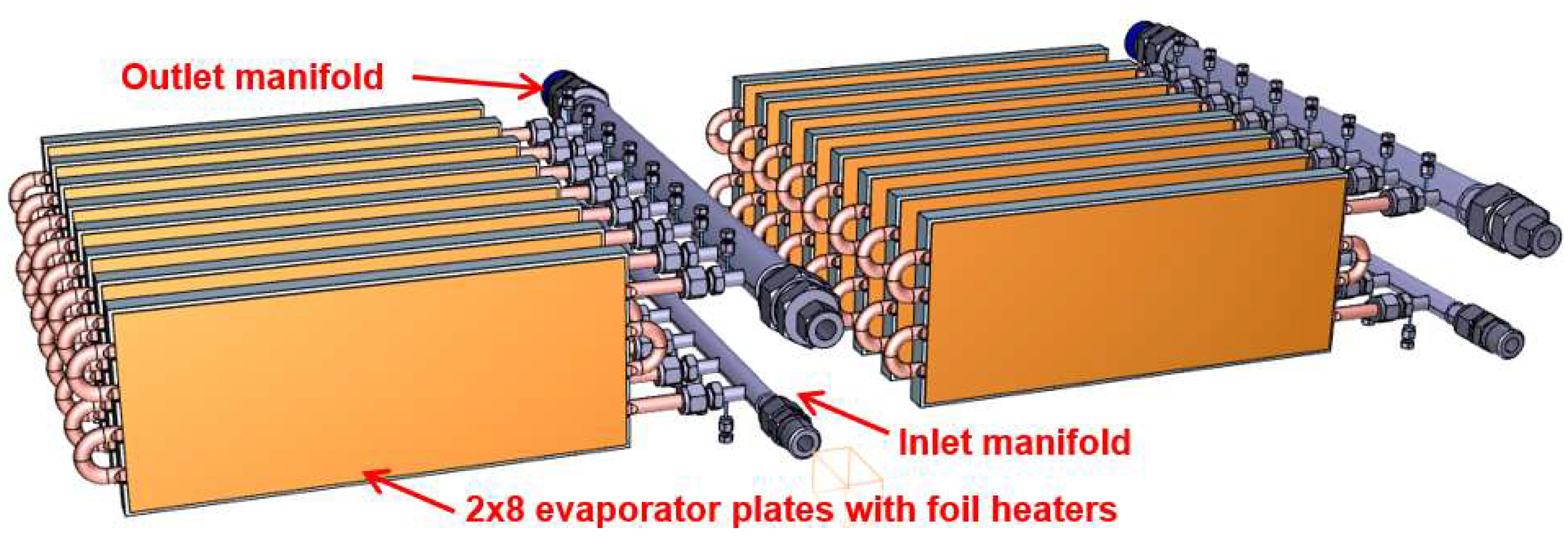
Figure 4.
CAD drawing of the condenser section.
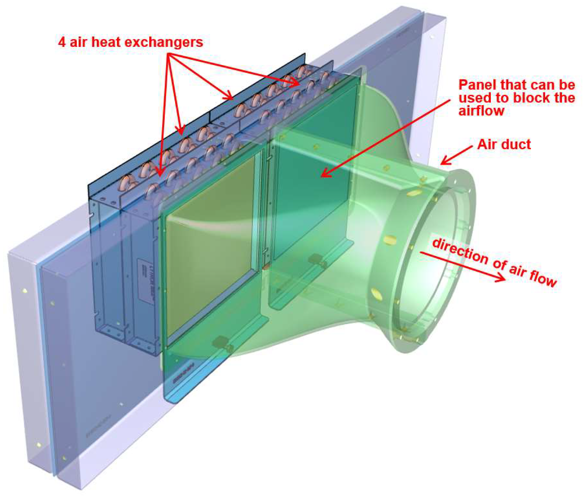
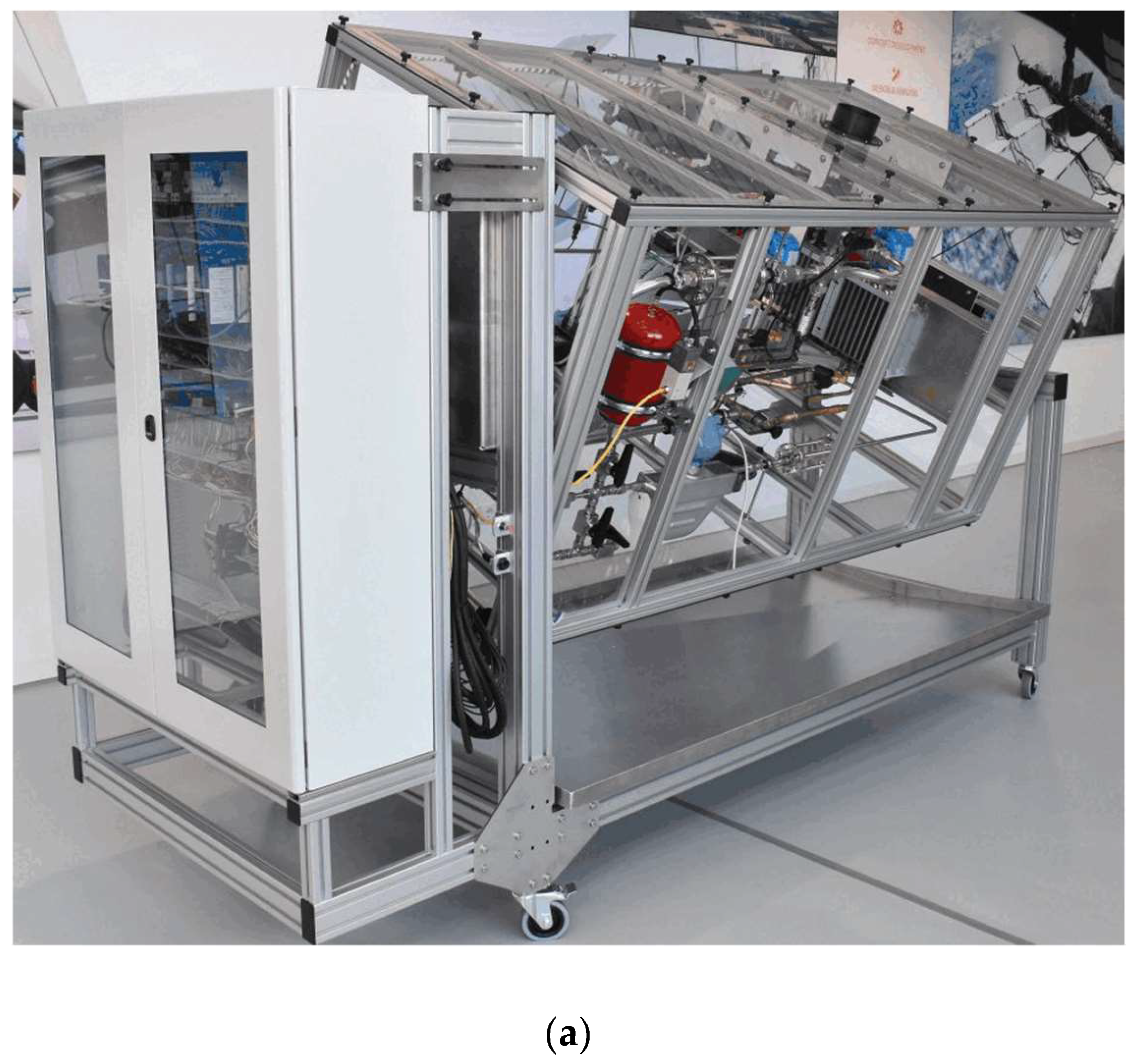
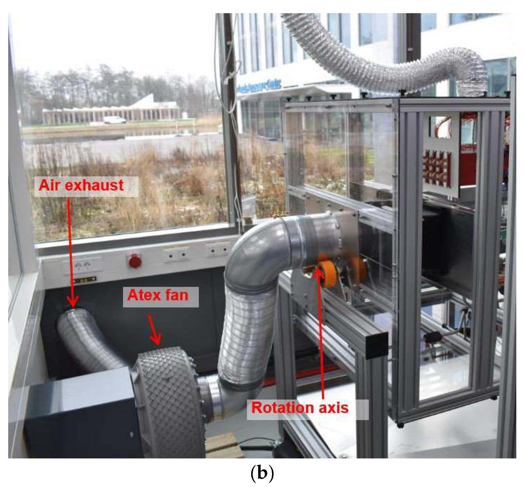
Figure 5.
(a) Photo of the 20 kW test setup in partly rotated (22.5°) orientation; (b) Photo of the fan that is used to force air through the air heat exchangers.
Figure 5.
(a) Photo of the 20 kW test setup in partly rotated (22.5°) orientation; (b) Photo of the fan that is used to force air through the air heat exchangers.
3. Test Results with Accumulator
3.1. Instantaneous Full Power
The BRAVA cooling system has to be able to handle variations in the heat load. The most extreme heat load variation is instantaneous full power on and off. Figure 6 (a) shows the applied heater power on the evaporator. At t=0.1 hours, the heat load is increased from 0 to 20 kW and at t=1.1 hours, it is reduced back to 0 W. Figure 6 (b) shows the control signals for the pump, the fan, and the bypass valve. The pump is set to 17%, which results in a mass flow of approximately 60 g/s, see figure 7 (a). The fan is set to 70% and the bypass valve remains closed during the test. Figure 7 (b) shows the measured temperatures at the two evaporator inlet branches (dashed and solid grey lines) and the temperatures at the outlets of the 16 evaporator plates (solid coloured lines for 8 evaporator outlets in branch 1, and dashed coloured lines for 8 outlets in branch 2). The black line indicates the saturation temperature, which is derived from the pressure at the evaporator outlet. At t=0.1 hours, the saturation temperature is set to 95 °C, by controlling the pressure in the accumulator (which is increased from 1 bar to 3 bara, see figure 8 (a)). When the evaporator heater power is turned on, the evaporator outlet temperatures quickly rise until the saturation temperature is reached and the liquid starts to boil. However, before the onset of boiling, the liquid is superheated to 115 °C before it quickly drops to the saturation temperature of 95 °C. This liquid superheat is further discussed in the next section.
Figure 9 (a) shows the vapour mass fraction at the evaporator exit. This vapour mass fraction is calculated from the evaporator inlet temperature, the mass flow, and the evaporator heat input. Figure 9 (b) shows the methanol liquid volume inside the accumulator. This volume is obtained by integrating the measured difference in the mass flows before and after the accumulator, and by dividing this mass by the liquid density.
3.2. Prevention of Liquid Superheat
In figure 7 (b), liquid superheat is observed before the methanol starts to boil. This liquid superheat is caused by the lack of boiling nucleation sites on the smooth tubing wall of the evaporator. Also, methanol is prone to liquid superheat e.g. because of its relatively high surface tension. One of the methods to prevent liquid superheat is to inject small gas bubbles (e.g. N2 or air) just before the evaporator. Figure 10 shows the measured temperature with the same test sequence as described in the previous section, except that a small amount (~16 ml) of N2 gas is injected before the evaporator when the liquid temperature reaches the boiling temperature. This gas injection prevents liquid superheat. The 20 kW system has a SpiroVent air separator that can expel the injected N2.
Liquid superheat is very geometry dependent. E.g. liquid superheat was not observed in tests with two-phase methanol with an evaporator made from bipolar plates from a fuel cell. A possible reason is that these bipolar plates have small sharp-cornered gaps [1], which act as nucleation sites for boiling.
3.3. Controlling the Evaporator Inlet Temperature with Bypass Valve or Fan Speed
In the measurements described in the previous sections, the liquid enters the evaporator with a temperature of around 70 °C. In the requirements for the 2-PC [2], it is specified that the evaporator inlet temperature can be controlled between 75 and 85 °C. In the 20 kW setup, the evaporator inlet temperature can be controlled with 2 methods:
- The fan speed can be varied; A lower fan speed results in less cooling capacity and thereby a higher evaporator inlet temperature. In an aircraft, this would be similar to reducing the airflow through the ram air heat exchanger with e.g. a ram air door.
- The condenser bypass valve can be opened. This increases the evaporator inlet temperature.
The fan and the bypass valve can be regulated via a PID controller that tries to control the evaporator inlet temperature to the setpoint value. Figure 11 (a) shows the measured temperatures at the evaporator inlet and outlet. Between t=0.5 and 2 hours, the evaporator inlet temperature is controlled by varying the fan speed and the temperature is set to 75, 80, and 85 °C. Between 2.4 and 3.9 hours, the inlet temperature is controlled by opening the bypass valve. Figure 11 (b) shows the control signals to the fan and bypass valve. This measurement shows that the evaporator inlet temperature can be controlled between 75 and 85 °C with these methods.
3.4. Influence of Orientation
In a two-phase cooling system, gravity effects could influence the system, e.g. causing dry-out of evaporators that are located higher than other evaporators. The 20 kW setup is designed such that it can operate in every orientation. For example, at the inlet of each evaporator is a flow restriction that consists of an orifice that has a diameter of 1.5 mm. This flow restriction results in a pressure difference of approximately 0.08 bar, which is larger than the pressure difference that can be caused in the evaporator by gravity, and this ensures an equally distributed flow over all 16 evaporators in each orientation. Figure 12 and 13 show the measured temperatures with the same test sequence as in section 3.1 ‘Instantaneous full power’, except that the system is rotated with 90°, 180°, and 270° (see figure 5 for a photo of a partly rotated system and the rotation axis). The results are very similar, which indicates that the system can operate in these orientations.
3.5. Influence of Blocked Condenser
A 2-PC can have parallel condensers. The system should still function (albeit with a reduced heat rejection capacity) if the airflow through one of the condensers is blocked. The frictional pressure drop strongly increases with increasing vapour mass fraction. When the airflow through a condenser is blocked, the vapour is not condensed back into liquid and this results in a higher pressure drop than in the other condenser branches. Since there has to be an equal pressure difference over each branch, this higher vapour fraction will result in a smaller mass flow through this blocked condenser (and a higher mass flow through the still functioning condensers). As a result, the cooling system will remain functioning, even if the airflow through one of the condensers is (partly) blocked. In order to test this, a measurement similar to the test described in section 3.1 (‘Instantaneous full power’) was carried out, except that the air flow through 2 of the 4 condensers is blocked by a metal plate (see figure 4). Figure 14 (a) shows the control values to the heater, pump and fan. Because the airflow through half of the condensers is blocked, the maximum heat rejection capacity of the system is reduced to 16 kW (with 100% fan speed). Figure14 (b) shows the measured temperatures at the evaporators and figure 15 the measured temperatures near the condenser. The air flow through condenser 1 and 2 is blocked and the temperatures at the outlet of these condensers (TcondOut1 and TcondOut2) are equal to the saturation temperature because the fluid is not cooled in these condensers. Also the temperature where the flows from condenser 1 and 2 are combined (TcondOut12) is at saturation temperature. The temperatures at the outlet of condenser 3 and 4 (TcondOut3 and TcondOut4) are well below saturation temperature. The temperature of the combined flows from all 4 condensers (TcondOut) is around 80 °C. This measurement shows that the system still functions if the airflow through some parallel condenser branches is blocked.
4. Test Results Without Accumulator
In the previous sections, a configuration of the setup with accumulator was tested. This accumulator controls the pressure (and thereby saturation temperature) in the system, and accommodates density changes (resulting from changes in liquid temperature and vapour fraction) of the fluid in 2-PC. The accumulator enables the loop to be completely filled with liquid (when no heat load is applied) and to be partly filled with vapour (when a heat load is applied).
It is also possible to have a 2-PC without accumulator [3]. A system without accumulator results in a huge mass saving, not only because of the absent mass of the accumulator, but also because of a large reduction of the fluid mass in the system (since a large part of the internal volume of the system is filled with vapour) [1]. However, without an accumulator, it is not straightforward to guarantee that the pump has subcooled liquid at the inlet, and to generate pressure in the system before the pump can be started. Also, once the system is started, control of the saturation temperature/pressure in the system is not straightforward. For this reason, the feasibility of a system without accumulator is tested with the 20 kW setup. The test setup has a manual valve between the accumulator and the loop. In order to fill the loop with the correct amount of fluid, the system is operated with a heat load of 20 kW with this valve open. When a steady state is reached, the valve between the accumulator and the loop is closed. The loop is now partly filled with methanol vapour and liquid and the tests described in the next sections were carried out.
4.1. Instantaneous Full Power
Figure 16 (a) shows the control signal for the pump, fan, bypass valve and evaporator heaters. Figure 16 (b) shows the measured temperatures and figure 17 shows the measured pressures. When the system is at rest, the pressure in the system is 0.25 bara. This is higher than the saturation pressure of 0.13 bara for pure methanol at 20° C. The reason is that the system contains some air, e.g. because some air is dissolved in the methanol before it is put into the system. When the pressure in the system is below ambient pressure, this dissolved air is released from the methanol which results in a pressure in the system above the saturation pressure from the methanol.
At t=0.04 hours, the heater power and fan are turned on. The heater power results in evaporation of some liquid that was present in the evaporator and the pressure and saturation temperature in the system increases. After a minute, the pump is turned on. As a result, more liquid enters the evaporator, which partly evaporates and results in a quick rise in system pressure and saturation temperature. In contrast to a system with accumulator, there is no liquid superheat. The saturation temperature keeps rising until a steady-state temperature of around 95 °C is reached. Since there is no accumulator, the pressure and saturation temperature in the system cannot be directly set. Instead, it depends on the heat load and on the fan speed. This is further discussed in the next section.
4.2. Control of Saturation Temperature with Fan Speed
In a system without accumulator, the saturation temperature can be controlled by varying the air flow through the air heat exchanger; when the fan speed is increased, a larger fraction of the condenser will be filled with liquid, and this reduces the pressure in the system. A decrease in fan speed increases the pressure in the system. Figure 18 (a) shows the control signals during the test, and Figure 18 (b) shows the measured temperatures. At t=0.04 hours, the heat load is set to 20 kW. Via a PID controller that regulates the fan speed, the saturation temperature is controlled to the setpoint temperature of 90 °C. After 30 minutes, the setpoint for the saturation temperature is increased to 95 °C, and after another 30 minutes, the setpoint is changed to 85 °C. At t=1.7 hours, the heat load is decreased to 10 kW and the setpoint for the saturation temperature is set to 90 °C, 95 °C, 85 °C, and 75 °C (each setpoint value is kept for 30 minutes). At t=3.7 hours, the heat load is decreased to 5 kW and the setpoint for the saturation temperature is set to 75 °C and 65 °C. The measurement shows that the saturation temperature can be controlled by the fan speed.
4.3. Control of the Evaporator Inlet Temperature
In a system without accumulator, the saturation temperature can controlled with the fan speed, see previous section. The evaporator inlet temperature can be controlled with two methods:
- By varying the opening of the condenser bypass valve
- By varying the pump speed
Figure 19 (a) shows the measured temperatures during a test. At t=0.04 hours, the heat load is set to 20 kW. The fan speed is controlled such that the saturation temperature in the system is 95 °C. When the condenser bypass valve is closed, the evaporator inlet temperature is approximately 75 °C. At t=0.5 hours, the setpoint for the evaporator inlet temperature is set to 80 °C and at t=1 hour, the setpoint for the evaporator inlet temperature is increased to 85 °C. Figure 19 (a) shows the measured temperatures during a similar test. In this test the bypass valve remains closed. Instead, the mass flow is varied: At t=0.55 hours, the mass flow is reduced from 57 g/s to 40 g/s and this reduces the evaporator inlet temperature to 66 °C. At t=0.9 hours, the mass flow is increased to 74 g/s and this increases the evaporator inlet temperature to 78 °C. At t=1.2 hours, the mass flow is increased to 100 g/s and this increases the evaporator inlet temperature to 81 °C.
4.4. Influence of Orientation
With accumulator, the 2-PC can start and operate in every orientation (see section 3.4). Without accumulator, the loop is partly filled with vapour, and the system can only be started when the pump is located at the bottom of the system and gravity supplies liquid to the pump inlet. Once the pump has started and flow is generated, the 2-PC functions in every orientation. This is illustrated by Figure 20, which shows the control signals and temperatures during a test where the system is rotated from 0° to 180° (so to ‘upside down’ orientation) around t=0.66 hours.
4.5. Imbalance in the Heat Load
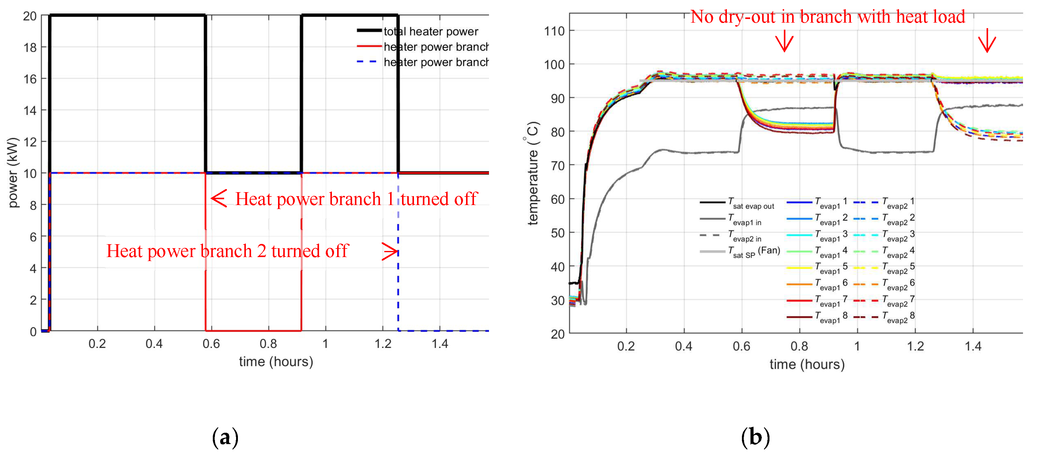
In the previous tests, the evaporator heat load was applied to all 16 parallel evaporator. However, in an actual application, the heat load can be unevenly distributed over the different parallel branches, for example due to a malfunction of a fuel cell. When there is no heat load in a parallel branch, it will cool down and fill with liquid. In a 2-PC without accumulator, this liquid has to come from other parts in the system, and this can results in dry-out. In order to test if the evaporator section can handle an imbalance in the heat load between the branches in a system without accumulator, a ‘worst case’ test was carried out in which half of the evaporators receive full power and the other evaporators suddenly receive no power. Figure 21 (a) shows the applied powers during the test. First, the heaters for all evaporators in both branches are turned on. At t=0.6 hours, the heaters in branch 1 are turned off. After another 20 minutes, the heaters in branch 1 are turned on and after another 20 minutes (at t=1.2 hours) the heaters in branch 2 are turned off. Figure 21 (b) shows the measured temperatures. Even with this extreme imbalance in the heat load, none of the evaporator branches shows any sign of dry-out. This means that the system without accumulator can handle an imbalance in the heat load.
5. Test Results with Small Accumulator
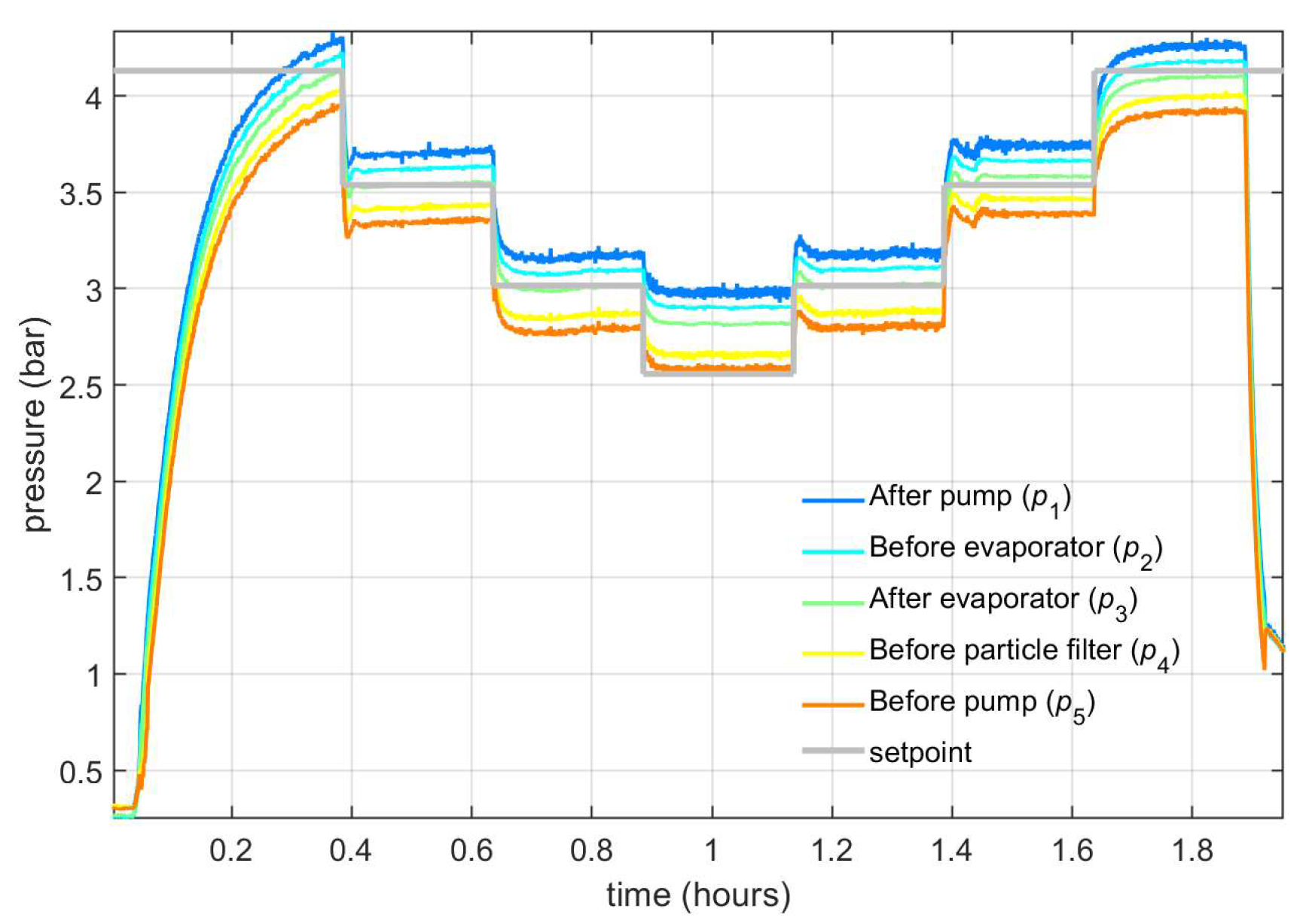
In section 3, test results with a ‘normal-sized’ accumulator were discussed. Such an accumulator enables the loop to be completely filled with liquid (when no heat load is applied) and to be partly filled with vapour (when a heat load is applied). The minimum volume of a ‘normal’ accumulator is equal to the volume of the system between the evaporator inlet and the condenser outlet (i.e. the part of the system where vapour can occur) plus the volume of the liquid needed for expansion due to temperature variations. For the 20 kW test setup, this minimum volume is approximately 3.5 litres, see figure 9.(b). In section 4, test results for a system without accumulator were discussed. Instead of using a ‘normal-sized’ or no accumulator, it is also possible to use a ‘small’ accumulator. Figure 22 shows the control signals and temperatures during a test with an accumulator with a volume of 1 litre. This is smaller than the minimal required volume of 3.5 litres to accommodate all fluid density changes. At the start of the test, the saturation temperature is set to 105 °C, which corresponds to a pressure of 4.1 bara, see figure 23. The pressure in the loop is lower than the pressure in the small accumulator and there is no liquid in the accumulator. When the heat load is applied (around t=0.04 hours), the pressure and thereby saturation temperature in the loop quickly starts to rise, until the pressure in the loop reaches the pressure in the accumulator. At that moment, some liquid will flow into the accumulator and the saturation temperature in the loop can be controlled with the accumulator. The setpoint for the accumulator is then decreased in steps from 105 °C, to 100, 95, and 90 °C. When the pressure in the accumulator is reduced, liquid flows into the accumulator. When the setpoint is set to 90 °C, the accumulator is completely filled with liquid and the saturation temperature cannot be further reduced by the accumulator.
The advantage of a small accumulator compared to a normal accumulator is the reduction in mass, not only because of the smaller mass of the accumulator, but also because of a large reduction of the fluid mass in the system. Also, there is no liquid superheat in the system with small accumulator. An advantage of a system with small accumulator compared to a system without accumulator is that it gives margin in the amount of fluid that is needed in the system, which can be convenient e.g. in case of a small leak in the system.
Figure 22.
Test with mall accumulator (a) Control signals; (b) Measured evaporator temperatures.
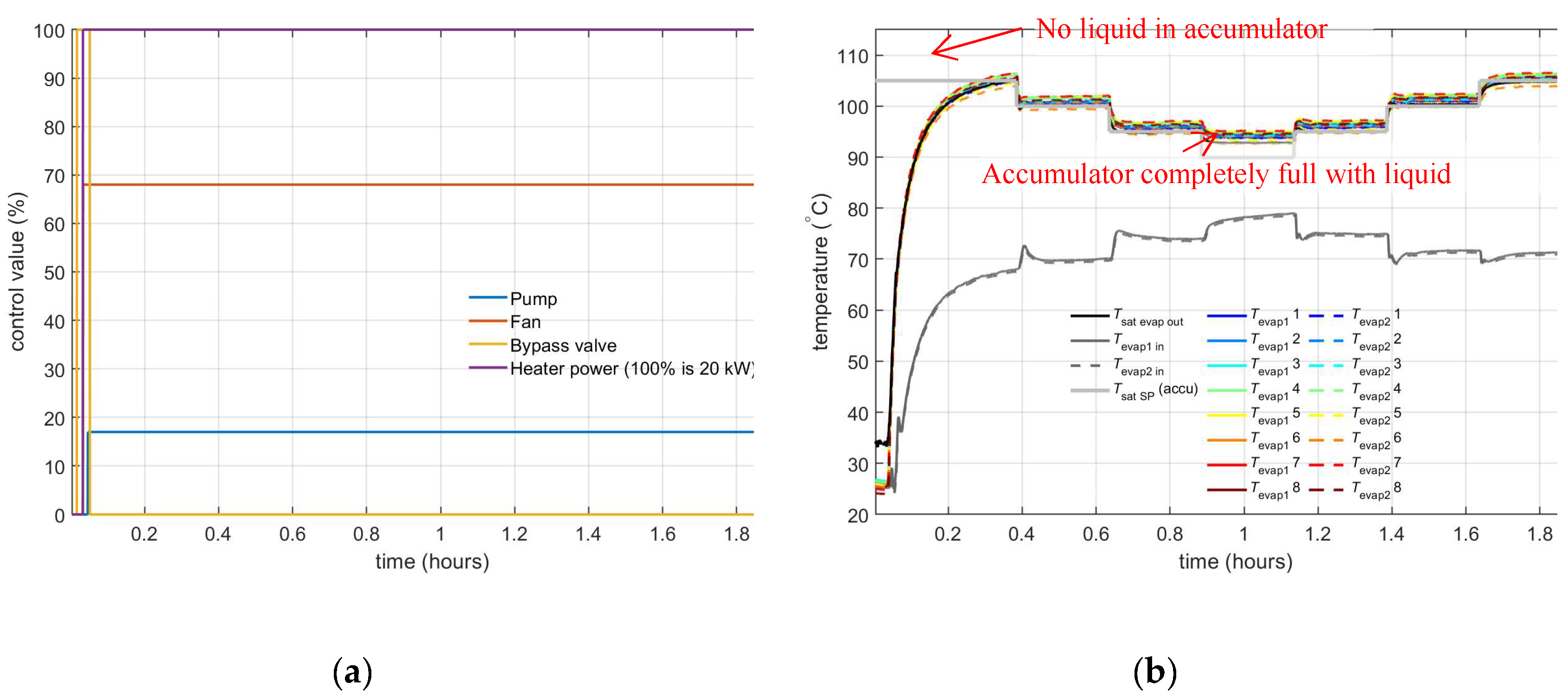
Figure 23.
Pressures for the test with small accumulator.
6. Discussion and Conclusion
With a 2-PC system with 20 kW cooling capacity, several concepts were tested. These tests show that saturation temperature control with a pressure controlled accumulator works well and that the subcooling at the evaporator inlet can be controlled via the fan for the air heat exchanger or via the condenser bypass valve. Also, the 20 kW system can operate in different orientations and the system still functions if the airflow through some parallel condenser branches is blocked.
A system without accumulator results in a huge mass saving, not only because of the absent mass of the accumulator, but also because of a large reduction of the fluid mass in the system. Test were carried out with a 20 kW system without accumulator and these tests showed that the saturation temperature can be controlled with the fan for the air heat exchanger. When a system without accumulator is in rest, the pressure in the system is 0.25 bar, which is below the ambient pressure. If the system is not air leak tight, air can leak into the system. Air leak into the system has no influence on the performance, since this air will be expelled from the system via the air separator (which has also been tested). However, an inleak of (moist) air into the system might have unexpected consequences, e.g. on corrosion. Another drawback of a system without accumulator is that it can only be started when the pump is located at the bottom of the system and gravity supplies liquid to the pump inlet. However, once the pump has started and flow is generated, the 2-PC functions in every orientation.
Author Contributions
Conceptualization, G. Mühlthaler and M.B. Buntz; methodology, H.J. van Gerner, S. Scholten; software, H.J. van Gerner, T. Luten; validation, H.J. van Gerner; formal analysis, H.J. van Gerner; investigation, H.J. van Gerner, S. Scholten; resources, H.J. van Gerner; data curation, H.J. van Gerner; writing—original draft preparation, H.J. van Gerner; writing—review and editing, T. Luten, G. Mühlthaler and M.B. Buntz; visualization, H.J. van Gerner, T. Luten; supervision, H.J. van Gerner; project administration, H.J. van Gerner; funding acquisition, H.J. van Gerner. All authors have read and agreed to the published version of the manuscript.
Funding
This BRAVA project is funded by the European Union’s Horizon under grant agreement number 10110149. This publication reflects the authors’ views. Neither the European Union nor the Clean Hydrogen Joint Undertaking can be held responsible for them.
Data Availability Statement
The raw data supporting the conclusions of this article will be made available by the authors on request.
Conflicts of Interest
The funders had no role in the design of the study; in the collection, analyses, or interpretation of data; in the writing of the manuscript; or in the decision to publish the results.
References
- van Gerner, H.J. ; Luten, T; Resende, W.; Mühlthaler, G.;Buntz, M.B. System analysis and comparison between a 2 MW conventional liquid cooling system and a novel two-phase cooling system for fuel cell powered aircraft. Energies (submitted). 2024. [Google Scholar]
- Resende, W. BRAVA deliverable report D2.1; PGS System Architecture and Requirements. Airbus 2023. [Google Scholar]
- Donders, S. N. L.; Banine, V. Y.; Moors, J. H. J; Verhagen, M. C. M.; Frijns, O. V. W.; van Donk, G.; van Gerner, H. J. Thermal conditioning system for thermal conditioning a part of a lithographic apparatus and a thermal conditioning method, Patent US8610089, 2013.
- van Es, J; Pauw, A; van Donk, G; van Gerner, H.J.; Laudi, E; He, Z; Gargiulo, C; Verlaat, B. AMS02 Tracker Thermal Control Cooling System commissioning and operational results. 43rd International Conference on Environmental Systems 2013.
- van Gerner, H.J. de Smit, M; van Es, J; Migneau, M. Lightweight Two-Phase Pumped Cooling System with Aluminium Components produced with Additive Manufacturing. 49th International Conference on Environmental Systems 2019.
- van Gerner, H.J. Kunst, R; van den Berg, T.H.; van Es, J; Tailliez, A; Walker, A; Ortega, C; Centeno, M; Roldan, N; Castaneda, C; Castro, C. Development and Testing of a Two-Phase Mechanically Pumped Loop for Active Antennae. 52nd International Conference on Environmental Systems 2023.
- van Gerner, H.J. Cao, C; Pedroso, D. A.; te Nijenhuis, A.K.; Castro, I; Dsouza, H. Two-phase pumped cooling system for power electronics; analyses and experimental results. 30th International Workshop on Thermal Investigations of ICs and Systems (THERMINIC) 2024.
Figure 6.
(a) Applied evaporator heater power; (b) Control signals.
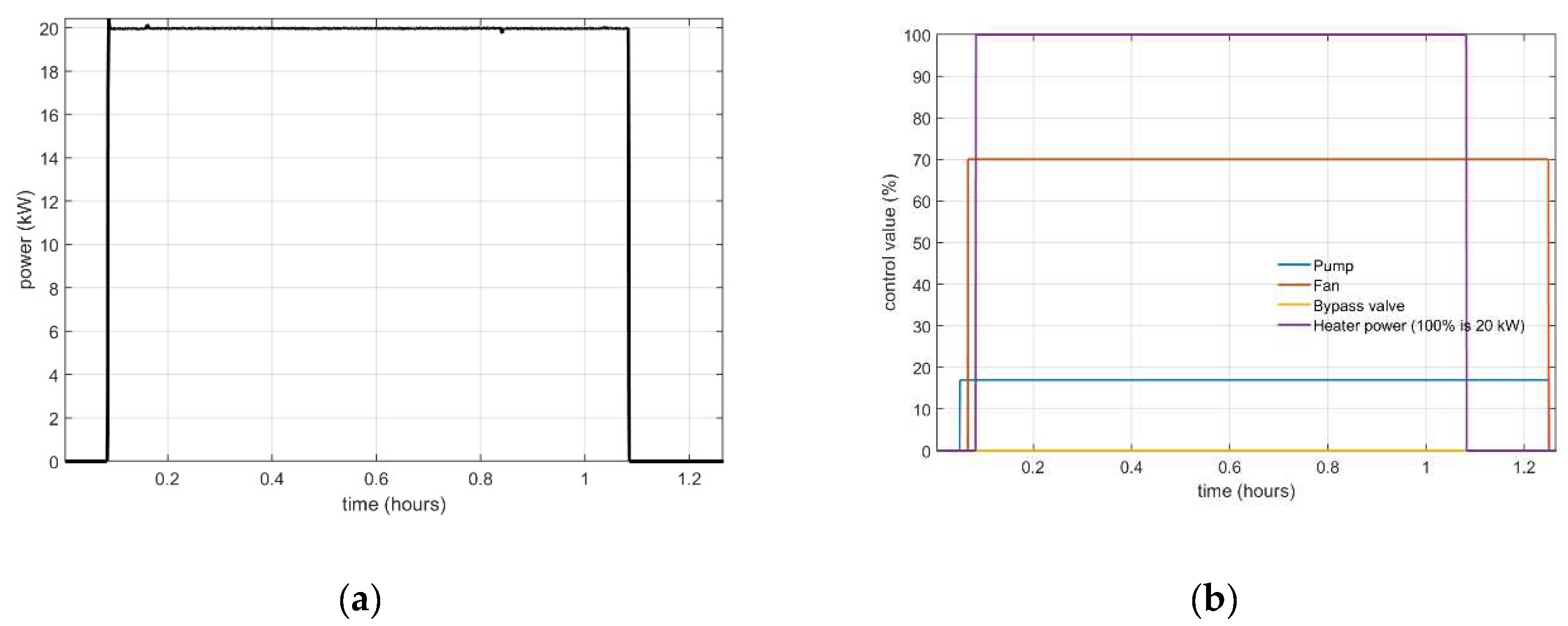
Figure 7.
(a) Measured mass flows; (b) Measured temperatures.
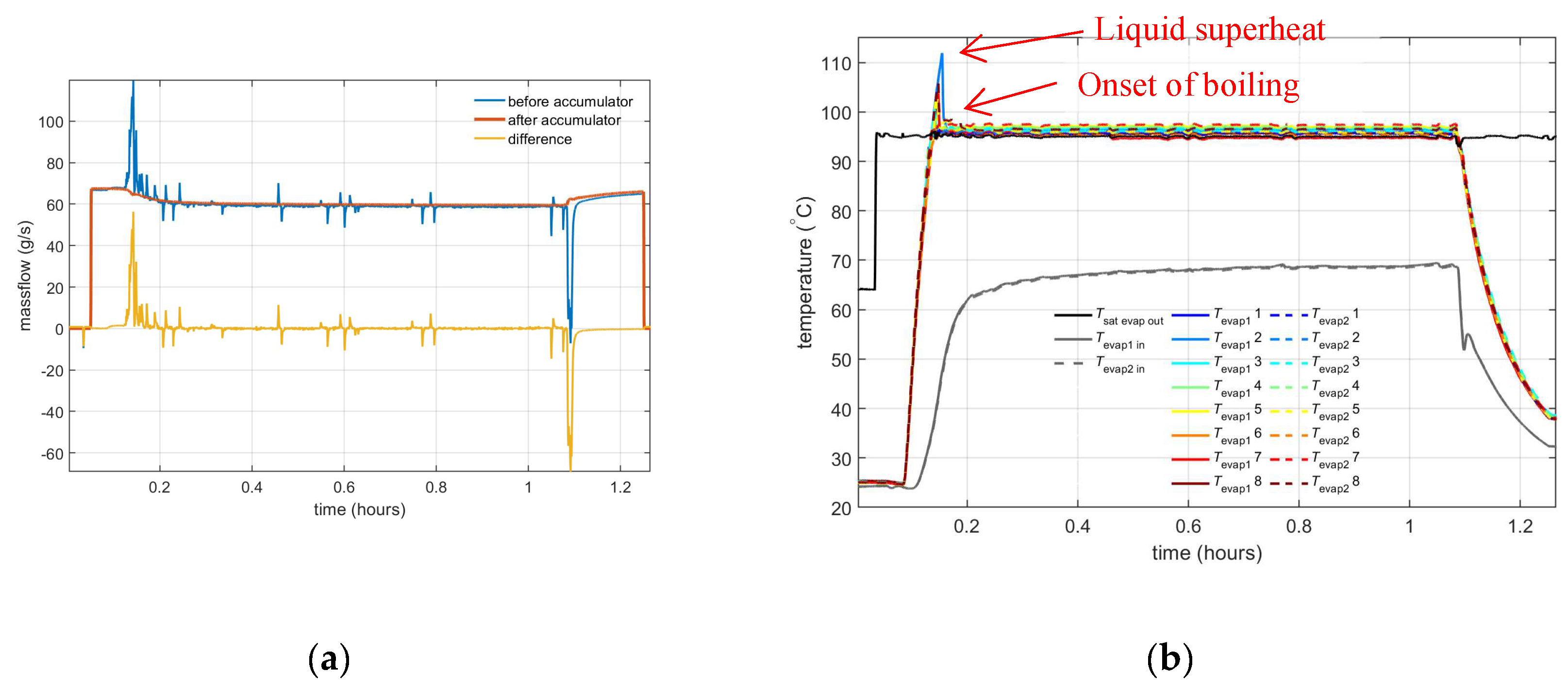
Figure 8.
(a) Measured pressures; (b) Measured pressure difference over the pump and evaporator.
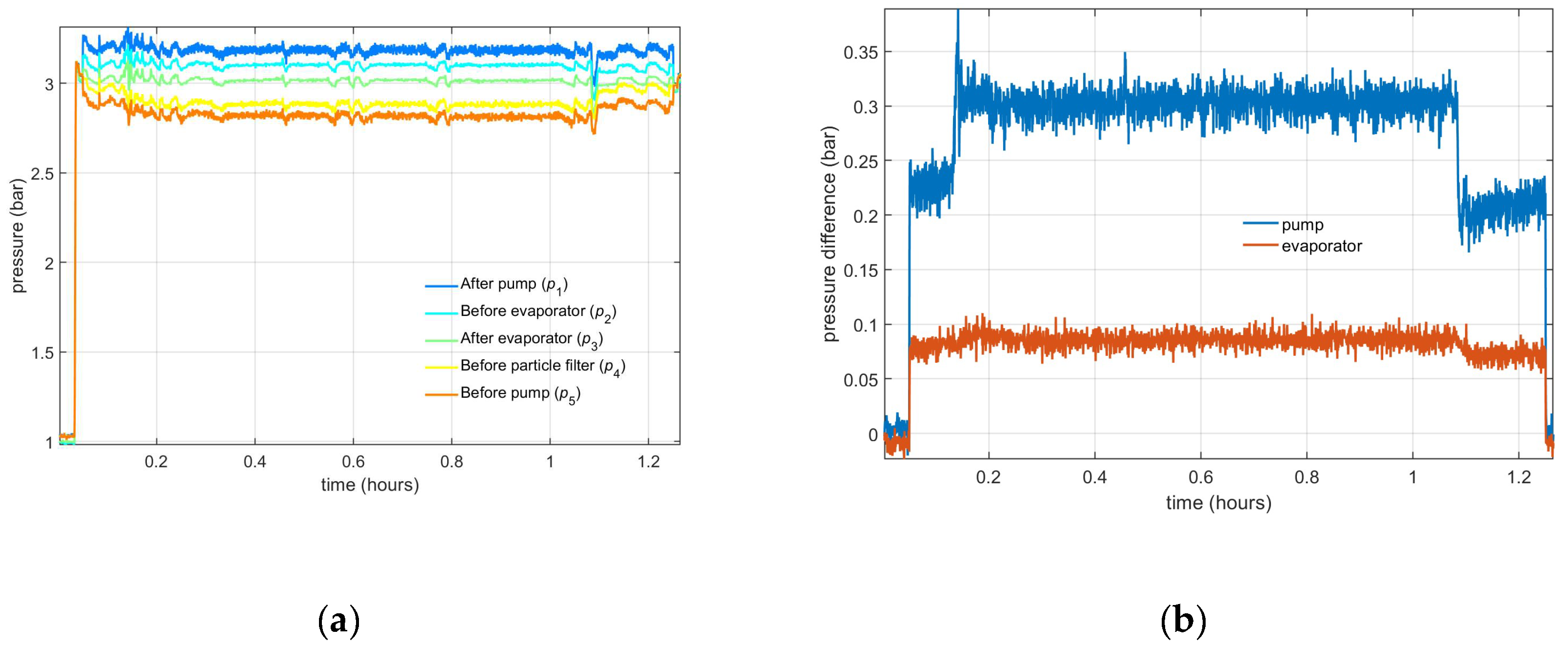
Figure 9.
(a) Calculated vapour mass fraction at evaporator outlet; (b) Methanol liquid volume in accumulator.
Figure 9.
(a) Calculated vapour mass fraction at evaporator outlet; (b) Methanol liquid volume in accumulator.
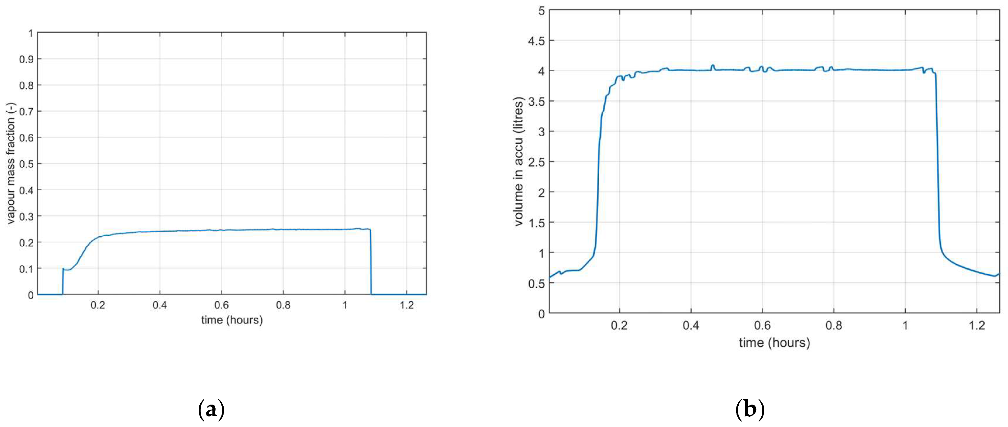
Figure 10.
Measured temperatures.
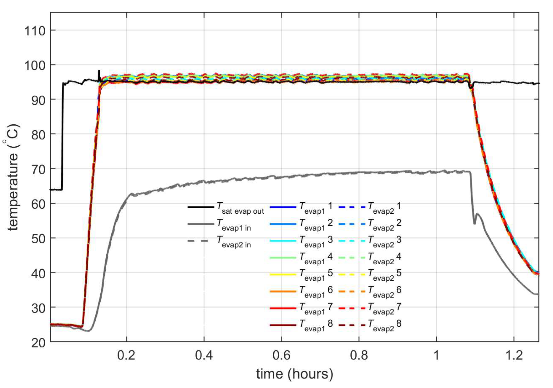
Figure 11.
(a) Measured temperatures; (b) Control signals.
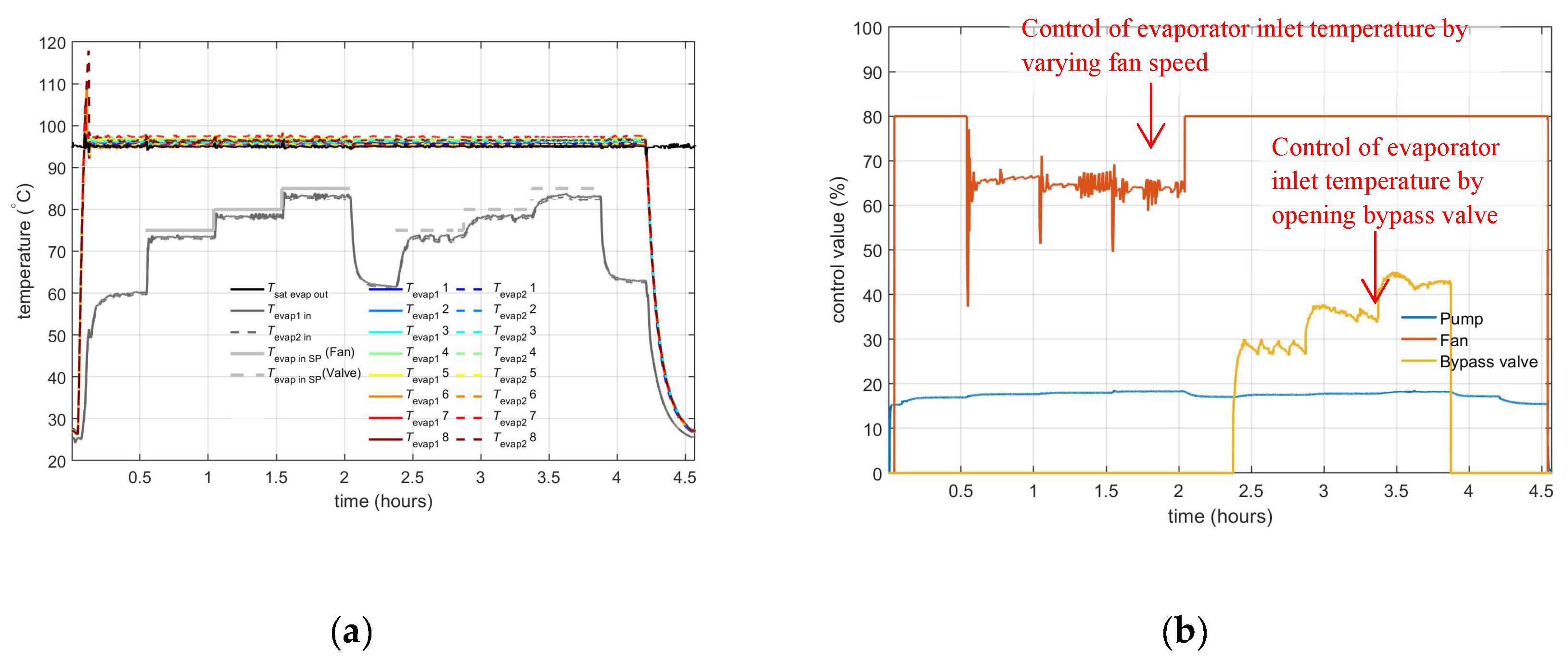
Figure 12.
Measured temperatures (a) with the system rotated 90°; (b) with the system rotated 180° (‘upside down’).
Figure 12.
Measured temperatures (a) with the system rotated 90°; (b) with the system rotated 180° (‘upside down’).
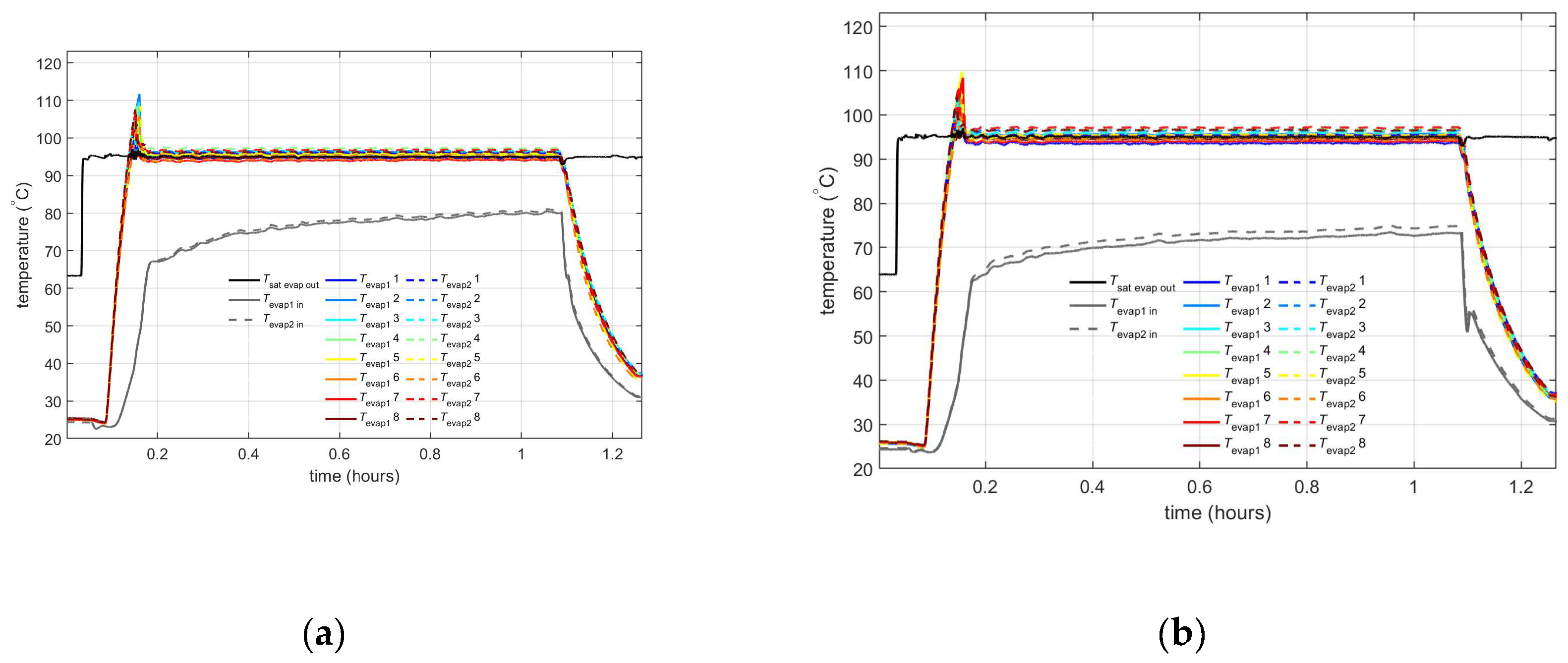
Figure 13.
Measured temperatures with the system rotated 270°.
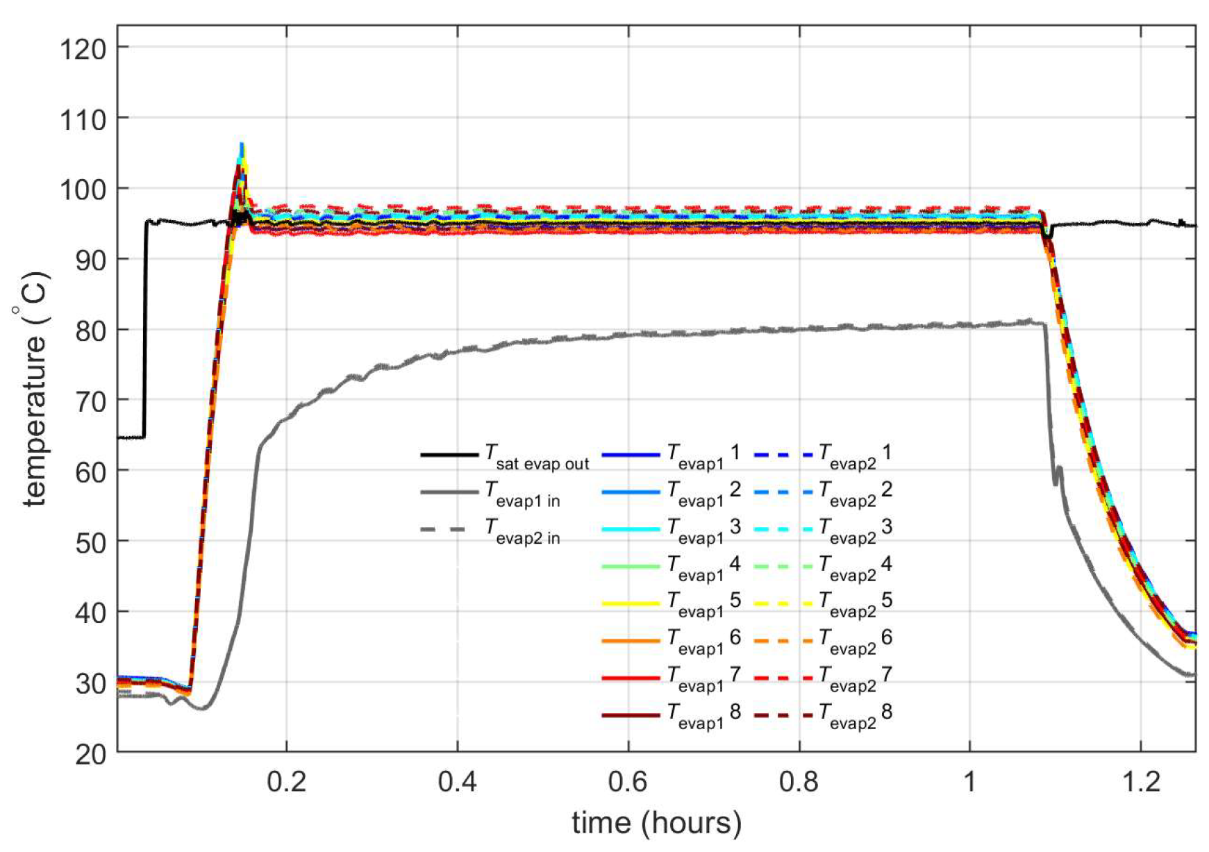
Figure 14.
(a) Control signals; (b) Measured evaporator temperatures.
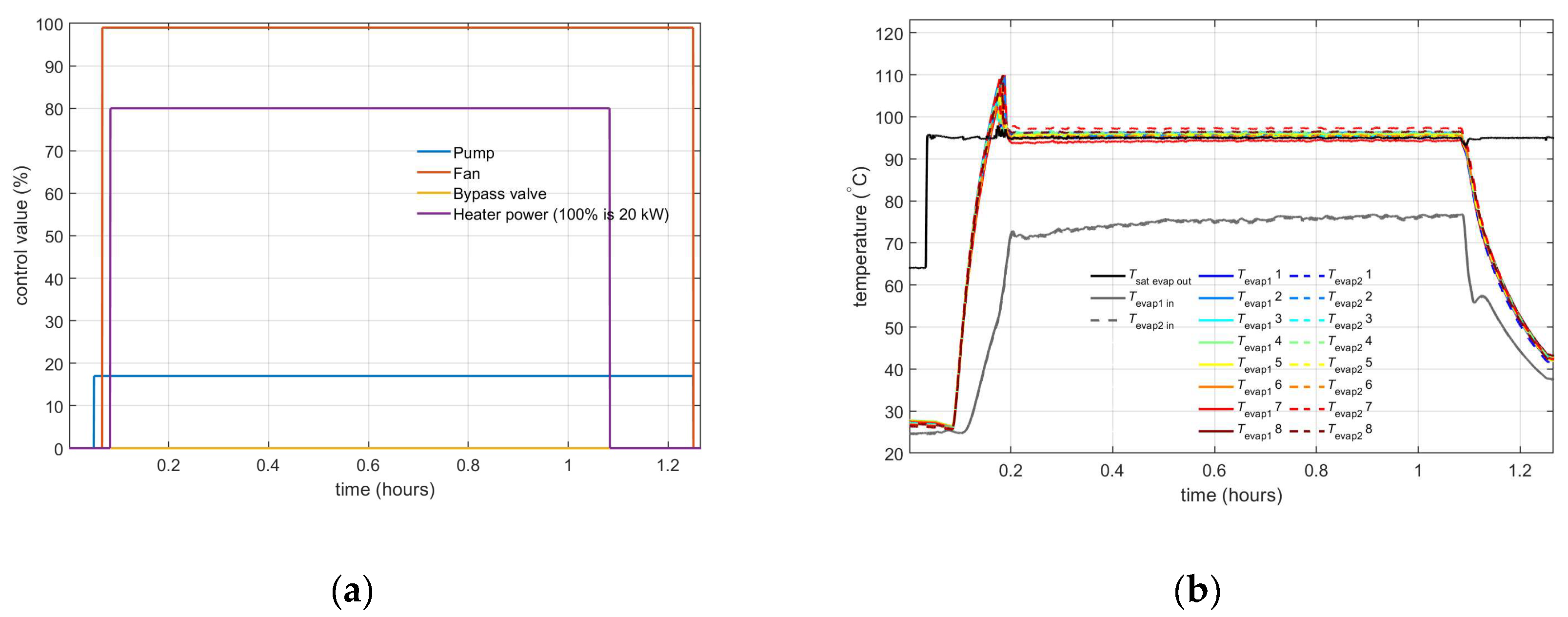
Figure 15.
Measured condenser temperatures.
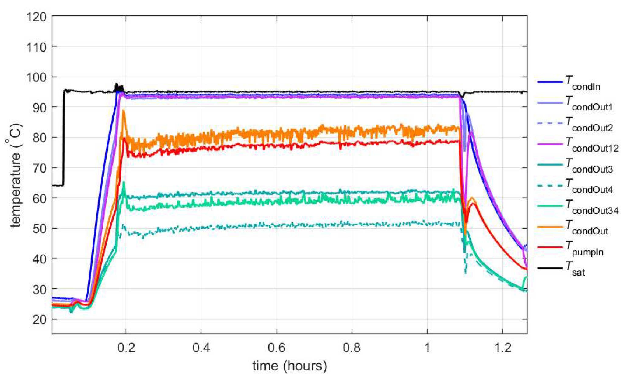
Figure 16.
(a) Control signals; (b) Measured evaporator temperatures.
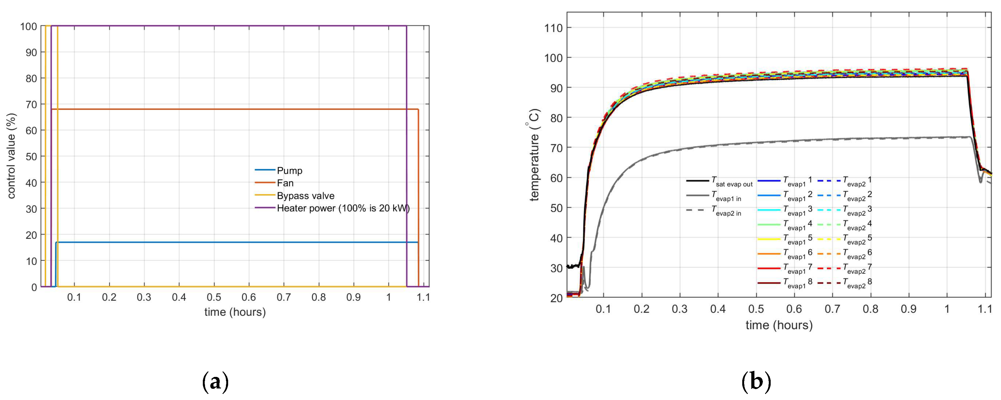
Figure 17.
Measured pressures.
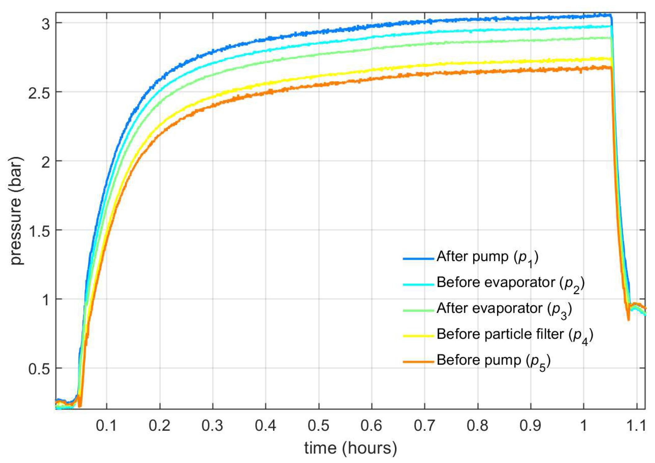
Figure 18.
(a) Control signals; (b) Measured evaporator temperatures.
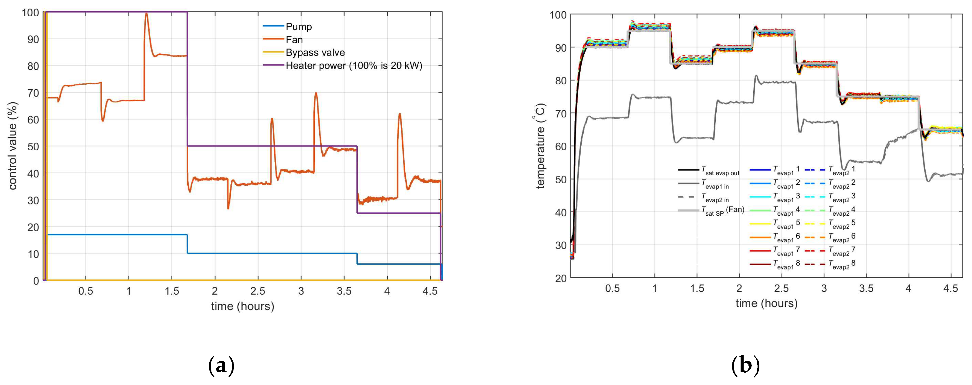
Figure 19.
Measured evaporator temperatures (a) with Tevap inlet control with valve; (b) with Tevap inlet control with pump.
Figure 19.
Measured evaporator temperatures (a) with Tevap inlet control with valve; (b) with Tevap inlet control with pump.
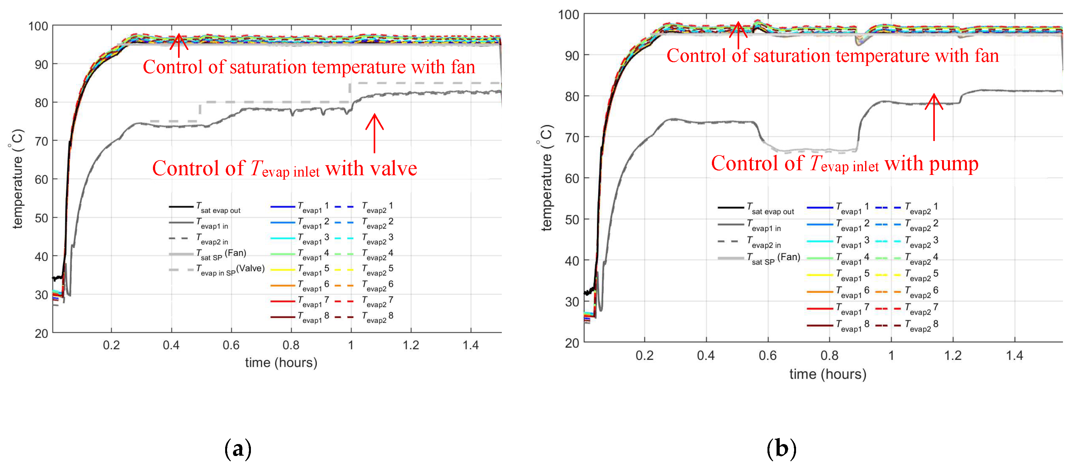
Figure 20.
(a) Control signals; (b) Measured evaporator temperatures.
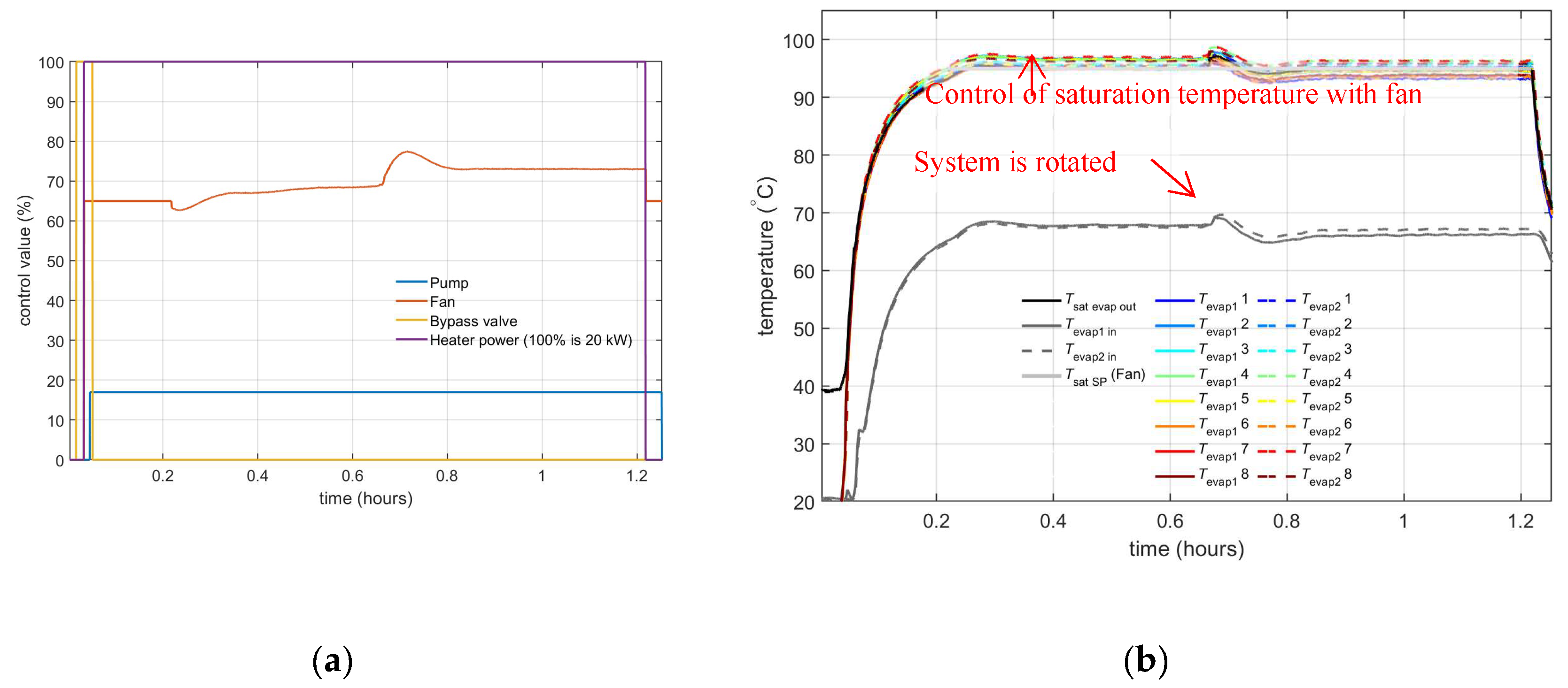
Figure 21.
(a) Evaporator heat input; (b) Measured evaporator temperatures.
Disclaimer/Publisher’s Note: The statements, opinions and data contained in all publications are solely those of the individual author(s) and contributor(s) and not of MDPI and/or the editor(s). MDPI and/or the editor(s) disclaim responsibility for any injury to people or property resulting from any ideas, methods, instructions or products referred to in the content. |
© 2025 by the authors. Licensee MDPI, Basel, Switzerland. This article is an open access article distributed under the terms and conditions of the Creative Commons Attribution (CC BY) license (http://creativecommons.org/licenses/by/4.0/).
Copyright: This open access article is published under a Creative Commons CC BY 4.0 license, which permit the free download, distribution, and reuse, provided that the author and preprint are cited in any reuse.


