
Submitted:
08 February 2025
Posted:
11 February 2025
You are already at the latest version
Abstract
This paper presents results of complimentary experimental (by electron microscopy, X-ray diffraction, diffuse reflectance, photoluminescence (PL) and FTIR spectroscopy) and computational (by molecular dynamics and DFT-based electronic structure methods) studies of oxide glasses of xP2O5-yMoO3-zBi2O3-(1-x-y-z)K2O system and glass ceramics based on them (crystal @glass), where the KBi(MoO4)2 complex oxide is the crystal component (KBi(MoO4)2 @glass). The behavior of the observed PL characteristics is analyzed in synergy with results of calculations of their atomic structures and changes in the oxygen environment of bismuth atoms during the transition crystal interphase glass. It has been shown that the optical absorption and PL characteristics of such systems are largely determined by content of Bi2O3 and MoO3 oxides in the initial charge, and by content bismuth ions in different charge states which exist in the produced glass and glass ceramics. It was found that the blue PL (spectral range 375 – 550 nm) of both glasses and glass ceramics originates from radiative transitions 3P1 1S0 in bismuth ions Bi3+. The yellow-red PL (range 550 – 850 nm) should be mainly associated with the luminescence of bismuth ions in lower charge states, Bi2+, Bi+ and Bi0. The thickness of the interphase layers of glass ceramics is estimated to be 1.5-2.0 nm. It has been shown that the changes in the spectra of optical absorption and PL / PL excitation of the glass ceramics occur due to the decrease in the number of oxygen atoms in the nearest surrounding of bismuth ions in the interphase region and these changes can be used for spectral probing of the formation and presence of interphase layers.
Keywords:
glass ceramics
; phosphate-molybdate glass
; atomic structure
; molecular dynamics
; luminescence
1. Introduction
Oxide glass ceramics are composite materials in which particles of an oxide crystal component are dispersed in an oxide glass matrix. Considerable interest in the study of such materials is associated with the wide range of their potential applications, in particular, in electronics [1], lighting [2,3], optical thermometry [4,5], biomedicine and dentistry [5,7,8], as sealing materials [9,10], etc.
Glass-ceramic materials can show a number of unique properties compared to those of their original components. These non-additive properties of glass-ceramics can be significantly determined, in particular, by existence of an interphase at the boundary between the glass and crystalline phases, which is characterized by specific atomic structure and, accordingly, unique characteristics [11,12,13,14]. For example, for electrically conductive glass-ceramics, modification of the interphase can reduce the resistivity of the material [15]. It was found that the types and strengths of chemical bonds in the interphase determine the creep resistance of the SiOC glass-ceramics [16]. Polarization of the interphase can also affect the dielectric breakdown performance of ferroelectric barium strontium titanate oxide glass ceramics [17]. As for luminescent glass-ceramics, formation of an interphase region can be manifested in a change in the luminescence spectral profile, decay time, or an increase of its intensity [13,18,19].
It is obvious that the study of peculiarities of formation of interphase regions in glass ceramics, the atomic structure and interaction processes in interphase areas is important for elaboration and application of novel composite materials. The development of new glass ceramics requires the selection of the optimal composition of the amorphous matrix, the concentration and particle size of the crystalline component, and the manufacturing and post-treatment parameters of the resulting product. Implementation of these procedures, in turn, requires a significant amount of experimental research, significant consumption of valuable reagents, electricity and time. Theoretical and computational modelling of the atomic structure and calculation of the electronic structure and properties of glass, crystal and glass ceramics can significantly reduce the number of such experiments and associated costs.
At present, theoretical and computational modelling of the electronic structure of interphases of composite materials is a top-level task of solid-state physics and materials science [20,21,22,23]. The most common approach in the computational study of the electronic structure of interfaces and interphases is the use of band-periodic methods based on the DFT formalism [1,20,22,23]. However, electronic structure calculation methods use an adiabatic approximation that does not allow effective modelling of the mutual diffusion of atoms of material components [24,25], which causes the appearance of the above-mentioned interphase layers.
The mutual diffusion of atoms of the composite components can be effectively modelled using molecular dynamics (MD) calculations [13,26,27]. It should also be noted that MD methods allow us to study bulk systems of several thousand atoms, while for more accurate DFT approximations, geometric optimization of a system of several hundred atoms usually overconsumes computer time. For this reason, in our computational studies we use molecular dynamics tools.
It should be noted that due to great complexity of atomic structure and composition glass-ceramic composites, the computational methods, and the MD method in particular, can only approximate the real atomic and electronic properties of such materials. In view of this, the correlation of the results of experiment and modelling is a necessary criterion for the adequacy of the selected calculation parameters. The luminescence experimental method used in this work makes it possible to examine the structure studied glass ceramics at the micro/nano scale. The luminescence centers (LCs) in solids are localized formations consisting of a center’s core (ions of mercury-like, transition and rare earth elements, etc.) and a shell (atoms/ions/molecules/defects of the immediate environment). The luminescent characteristics of a crystal are primarily determined by the LCs core - the energy structure of its electronic and vibrational levels. However, the characteristics of the cores can be significantly modified by the interaction with the environment and the symmetry of the latter. This feature allows us to qualify the center core as a luminescent probe of the solid state structure. In this work, we use the luminescent probe, where the bismuth ion is the core.
The choice of glass ceramics for experimental studies was made in accordance with the following considerations. It is known that only certain oxides, in particular B2O3, P2O5, SiO2, GeO2, As2O3 are glass-forming, while other oxides are either only conditionally glass-forming oxides (e.g. Bi2O3) or modifiers (e.g. A2O where A is an alkali metal) [28,29]. Among these, As2O3 is toxic, GeO2 is quite expensive, and SiO2 is very refractory. Glasses based on B2O3 and P2O5 are often hygroscopic, so we focused on phosphate glasses, which when the oxygen to phosphorus ratio [O]/[P] > 3 [30] are quite resistant to moisture. Here, we present results for the bismuth-containing phosphate-molybdate system xP2O5-yMoO3-zBi2O3-(1-x-y-z)K2O. The introduction of bismuth and molybdenum into the system provides absorption in the UV region of the spectrum and can be accompanied by luminescence of the system in a wide range of light, from the UV to red and IR [31,32,33]. This, along with other important useful properties of bismuth-containing glasses and glass ceramics, determines the continuous interest shown by researchers and technologists [34,35,36].
As for the crystalline component, KBi(MoO4)2, its choice was motivated by the composition of chemical elements, which is close to the composition of glass matrix. In our opinion, this approach made it possible to expect that the interphase space would have an "intermediate" chemical composition, and mechanical stresses in the glass ceramics would be minimized.
Previously, we have already studied some samples of phosphate-molybdate glass ceramics based on the amorphous matrix 31.79P2O5-25.43MoO3-5.69Bi2O3-37.09K2O and micro/nanocrystals KBi(MoO4)2:RE, where RE = Eu, Pr [37,38]. The study of the luminescent properties of these glass ceramics under direct excitation of RE ions (λex = 473 nm) showed that the emission bands of RE ions undergo a broadening compared to the case of luminescence of KBi(MoO4)2:RE crystals [39]. In addition, in the case of glass ceramics with KBi(MoO4)2:Eu phosphor, an abnormally intense broad emission band in the region of 5D0 ® 7F0 transition of Eu3+ ion (560-582 nm) was observed [37]. Based on these experimental results, it was assumed that RE ions partially migrated to the glass component. The rather high intensity of the red radiation of Eu3+/Pr3+ ions in these test samples indicated the prospects for further development of luminescent coatings for chip LEDs on the base of xP2O5-yMoO3-zBi2O3-(1-x-y-z)K2O - KBi(MoO4)2:RE glass-ceramics. That is why, a detailed experimental study of the optical, in particular luminescent, properties of this type of materials and their analysis using the results of theoretical modelling was found to be reasonable.
This paper presents the results of comprehensive studies using experimental and computational methods of oxide glasses of the xP2O5-yMoO3-zBi2O3-(1-x-y-z)K2O system and glass ceramics based on them, where the KBi(MoO4)2 complex oxide is the crystal component (KBi(MoO4)2 @Glass) . The photoluminescence (PL) of such glasses and glass ceramics based on them was detected for the first time. The behavior of the observed PL characteristics is analyzed in synergy of results of calculations of their atomic structure and changes in the oxygen environment of bismuth atoms during the "crystal ® interphase ® glass" transitions. In particular, it has been found that the structure of the nearest oxygen environment of bismuth in the interphase regions of the composite differs significantly from the structure of the bismuth environment both in KBi(MoO4)2 crystal and in the glass, which affects the optical macro-characteristics of the studied materials.
2. Materials and Methods
2.1. Samples
Phosphate-molybdate glasses of the xP2O5-yMoO3-zBi2O3-(1-x-y-z)K2O system (x – in the range 23.01 – 40.31; y – in the range 13.55 – 46.02; z – in the range 1.00 – 5.69) were made by conventional melt quenching technique. The thoroughly grinded mixtures of K2CO3, KH2PO4, Bi2O3 and MoO3 analytically pure raw materials have been heated in platinum crucibles up to 1000 °C and kept at this temperature for 2 hours for homogenization. The melt obtained was poured onto a pre-heated (t ≈ 400 °C) glass-carbon crucible and annealed in a furnace with temperature 450 °C for 2 h. Afterwards the furnace was turned off for natural cooling. The compositions of the glasses and some other experimental and calculated characteristics are accumulated in the Table S1 (Supplementary Materials). The samples are marked as G1, G1.48, …, consistently with the Bi2O3 content increasing.
Glass-ceramics samples have been prepared in a similar manner. The calculated amount of crystalline powder has been added to the glass prepared by the given above melt quenching technique in a glass-carbon crucible at 450 °C under constant stirring. The mixture obtained has been annealed for 2 hours. Afterwards the furnace has been switched off for natural cooling. The glass-ceramic samples containing 10 wt. % of KBi(MoO4)2 crystalline powders in the G5.69 glass are noted as GC5.69. The details of the crystal synthesis can be found in [40].
The photoluminescence (PL) and PL excitation spectra (PLE) were recorded on as-prepared samples of glass and glass-ceramics. X-ray diffraction and diffuse light reflection studies were performed on grinding glasses and glass-ceramics.
2.2. Experimental Equipment
Densities of the samples were measured three times for each glass by well-known Archimedes method. The obtained averaged values with standard deviations are collected in Table S1. Scanning electron microscope Tescan Mira 3 LMU with a 20-nm electronic beam diameter was used for SEM measurements. Powder X-ray diffraction (XRD) patterns were measured with use of Shimadzu XRD-6000 diffractometer (curved pyrolytic graphite counter monochromator, CuKα radiation with λ = 1.54184 Å) operating in Bragg–Brentano (Θ/2Θ) geometry (2Θ = 5 – 70°). The IR spectra were measured with user of a PerkinElmer Spectrum BX FTIR device. Diffuse reflection spectra of the samples were measured with a Perkin Elmer Lambda 950 spectrometer. The PL emission and excitation spectra were measured using Horiba/Jobin-Yvon Fluorolog-3 spectrofluorometer equipped with 450 W xenon lamp. All the experiments were performed at room temperature of the samples.
2.3. Calculation Approach
To model the atomic structure of glasses and interphase regions in glass-ceramics based on glass matrices xP2O5-yMoO3-zBi2O3-(1-x-y-z)K2O and KBi(MoO4)2 crystals, three-dimensional periodic cells were constructed using structural data processing utilities of the BIOVIA Materials Studio 2019 software package [41].
The initial filling of the periodic cells (the vacuum layer of the cells in the case of interface, see Supplementary Material, Figure S1) was performed using Amorphous Cell Packing utility [41]. The molecular fragments (molecular groups and cations) of initial filling of the cells were chosen of the base of analysis of experimental data on FTIR spectroscopy (details will be given below, in Sec. 3.2.1). The atomic structures of glasses and interphases were calculated using MD methods implemented in Forcite utility of Materials Studio package. Using additional calculations, we found that for the best compliance between the calculation results and experimental data, we should use the parameters of interatomic interaction corresponding to the set of Universal Forcefield Types [41] with options for specific elements given in Supplementary Material (Table S2). The charges of all atoms in the cells were set using the Charge equilibration utility with the set of parameters QEq_charged1.1 [41].
We used the following scheme for calculating the atomic structure of glasses MD methods. Such a scheme is a typical approach in the present-day modelling of the atomic structure of oxide glasses (see [42]), and in the case of the glass cells included the following steps:
- Melting at Tmelt = 5000 K (NVT, δt = 1 fs, t = 100 ps), Nose Thermostat, other calculation parameters were set default [41].
- Quenching to T = 300 K (NVT, δt = 1 fs, quenching rate = 40 K/ps).
- Equilibration at T = 300 K and P = 1 atm (NPT, δt = 1 fs, t = 100 ps). This step allows us to obtain the calculated densities of all modelled glass samples.
- Production at T = 300 K (NVT, δt = 1 fs, t = 100 ps). We obtained 10 different structures to provide sufficient statistical weight in the subsequent analysis of the properties of the studied systems. The use of about 10 such structures to average the calculated characteristics is usually considered sufficient to adequately describe the properties of glasses [43].
Geometry optimization (Fine optimization criteria, external pressure 10-4 GPa, full cell optimization [41]). It is believed that a necessary step in obtaining an adequate atomic structure of glass by MD methods is its additional geometric optimization in the same approximations [43,44].
In the case of the Crystal@Glass interphase cells, the same MD scheme was applied as for the glass cells, except step 3) "Equilibration at RT", since the NPT ensemble cannot be used in the presence of frozen atoms in the cell (in the case of glass, this step was needed primarily to obtain the calculated density value ρ and compare it with the experimental data).
The structural characteristics and macro-properties of glasses and interphase layers, the atomic structure of which was calculated by MD methods, were calculated using Analysis procedures of Forcite utility [41].
Due to significant consumption of computer resources, it is practically impossible to perform DFT calculations for such large periodic cells as we used in the MD method (Figure S1). Therefore, for geometric structure optimizations by the DFT method of glasses and interphases, we used smaller cells, which (in the starting geometry) had a size of 12x12x12 Å and orthogonal lattice vectors (example of such cell is presenter in Supplementary Material, Figure S2). To obtain the starting geometry of atomic positions, the 12x12x12 Å cells were filled with atoms and molecular fragments of glass or interphase in certain proportions. Such proportions (chemical composition of elements) in the case of glass were taken from experimental data, and in the case of interphase, they were determined from the results of MD calculations of the atomic structure. The initial filling of the 12x12x12 Å cells was performed using the Amorphous Cell Packing utility with a set of atoms and molecular fragments. The parameters of the procedure for initial cell packing for DFT calculations were chosen the same as in the case of filling large cells used in MD calculations.
In order to create a sufficient statistical base for analysis, 8 cells of 12x12x12 Å of glass composition # 7 (see Supplementary Material, Table S1) with the same chemical composition and density but different atomic structures were generated using Amorphous Cell Packing. Similarly, 8 cells were generated with the composition and density corresponding to the interphase of KBi(MoO4)2 crystal with glass # 7. A full geometric optimization procedure (both atomic coordinates and cell parameters were optimized) in the DFT approximation was applied to each of the 16 structures. In subsequent analysis, the results of calculated atomic structures were averaged over 8 glass and 8 interphase DFT-optimized cells.
For geometry optimizations of the glass and interphase cells, we used the DFT-based band-periodic pseudopotential electronic structure method implemented in CASTEP, which is part of the Materials Studio package [41]. In these calculations, ion-electron interactions were modelled by nonlocal pseudopotentials of the Vanderbilt type [45]. Exchange-correlation effects were taken into account in the GGA approximation using the PBE potential approximation [46]. The energy threshold defining the size of the plane wave basis was 340.0 eV. The geometry of the nuclei was optimised using the Broyden-Fletcher-Goldfarb-Shenno (BFGS) minimisation technique [47] with the simultaneous convergence criterion for energy and force on the atoms, which were 10-5 eV per atom and 0.03 eV/Å per atom, respectively. The geometric optimisation calculations were performed only for the point G of the Brillouin zone.
3. Results and Discussion
3.1. Part 1. Characterization of the Glasses and Glass-Ceramics
Characteristics of the representative glass samples of xP2O5-yMoO3-zBi2O3-(1-x-y-z)K2O system were experimentally measured for different combinations (x, y, z) values. Due to significant number of experimental measurements required to study the whole set of synthesized glass compositions 1 – 7 (see SM, Table S1), the experimental studies in this paper were limited to only several representative glass compositions (glass compositions # 1, 2, 4 and 7 in Table S1 correspond respectively to the samples denoted as G1, G1.48, G4.12 and G5.69, in Table 1 below) and GC5.69 glass ceramics.

Table 1.
Optical band gaps, Bi2O3 and MoO3 content, and normalized intensities of the PL bands
| Glass name | Eg, eV | Oxide content, mol % |
MoO3 / Bi2O3 ratio | Normalized PL intensity, r.u. | ||||
|---|---|---|---|---|---|---|---|---|
| I(Tot) | I(Blue) | I(YR) | ||||||
| Bi2O3 | MoO3 | |||||||
| G1 | 3.62 | 1.00 | 11.17 | 11.17 | 1.00 | 1.0 | 1.0 | |
| G1.48 | 3.61 | 1.48 | 16.53 | 11.17 | 1.23 | 1.5 | 1.1 | |
| G4.12 | 3.44 | 4.12 | 46.02 | 11.17 | 4.24 | 8.4 | 2.9 | |
| G5.69 | 3.60 | 5.69 | 25.43 | 4.47 | 4.89 | 7.5 | 4.1 | |
3.1.1. SEM Data
Characteristic SEM images for the glass samples, crystal, and the glass ceramics are shown in Figure 1.
Figure 1.
SEM images of the G5.69 glass (a), KBi(MoO4)2 powder (b,c), and GC5.69 glass-ceramics samples (d,e).
Figure 1.
SEM images of the G5.69 glass (a), KBi(MoO4)2 powder (b,c), and GC5.69 glass-ceramics samples (d,e).
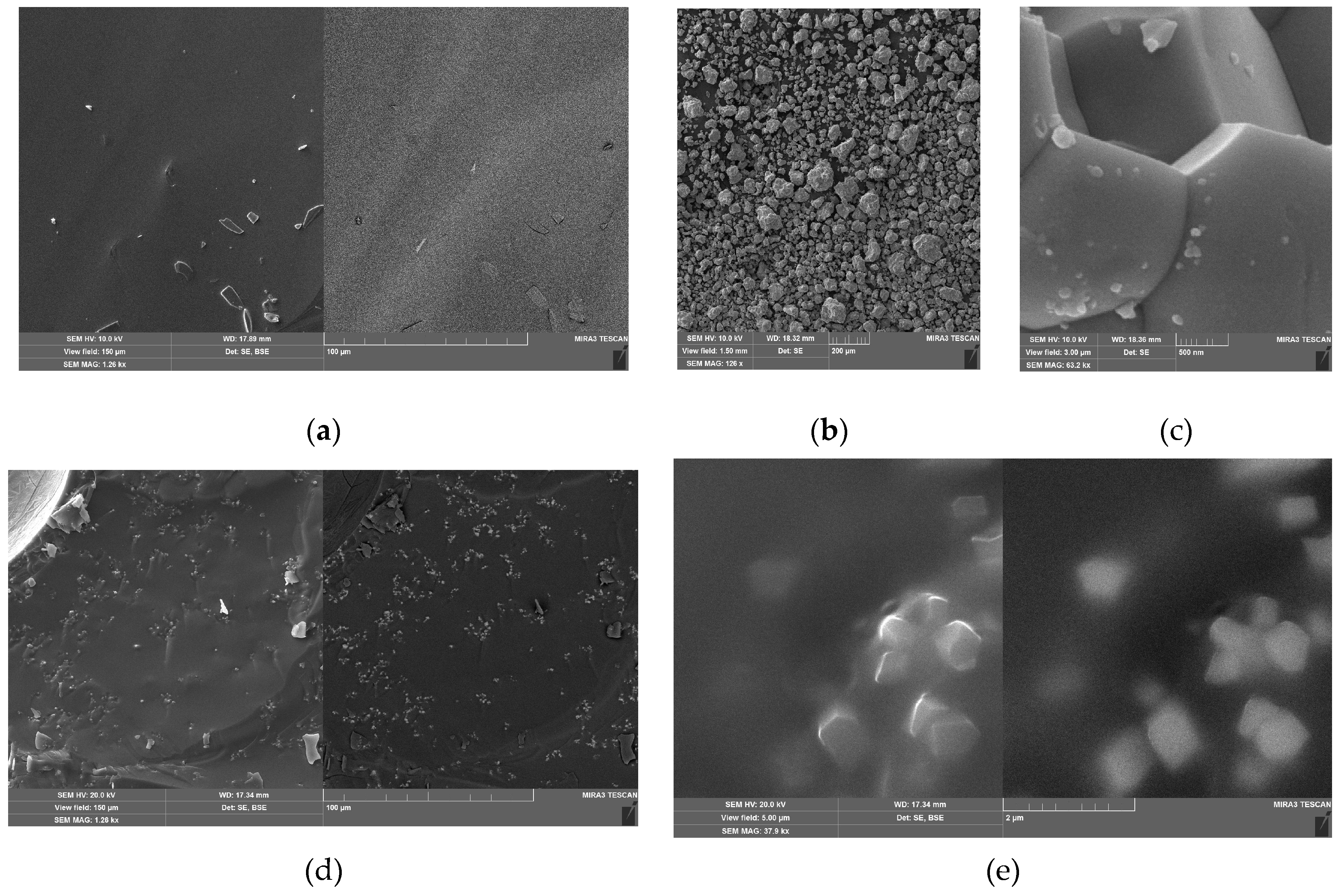
It can be seen that the glass surface is quite smooth. There are also small fragments of glass on the surface (the left part of Figure 1a corresponds to the image of the formed SE, and the right part to the BSE), which were formed as a result of cleavage during the preparation of the sample for measurements. The polycrystalline powder contains agglomerates up to 100 µm in size (Figure 1b). These agglomerates consist of prismatic micro- and nano-sized crystallites (Figure 1c). The studied glass ceramics contain a significant number of crystallites, which lie both near the surface (SE image, left part in Figure 1d) and in the sample bulk (BSE, right part in Figure 1d). A detailed view of the area of the glass-ceramic sample with crystalline inclusions (Figure 1e) shows similar crystal morphology in Figure 1c and Figure 1e. That is, under the above conditions of obtaining glass-ceramics, no significant transformations of the crystal component occur. This result is quite expected, since the melting point of Kbi(MoO4)2 crystals is about 750° C [39].
3.1.2. Diffuse Reflection Data
Diffuse reflection spectra for the listed in Table 1 samples are shown in Figure 2a. As the Figure shows, the reflection coefficient for the studied glasses is low (R < 20 %) in the UV spectral range (λ < 370 nm), while in the visible range, at λ > 400 nm, the reflection coefficient increases to 50 – 80 %.
Figure 2.
Diffuse reflection spectra of the: (a) G1(1), G1.48 (2), G4.12 (3), and G5.69 glasses (4); (b) KBi(MoO4)2 crystalline powder (1), G5.69 glass (2), and GC5.69 glass-ceramics (3)
Figure 2.
Diffuse reflection spectra of the: (a) G1(1), G1.48 (2), G4.12 (3), and G5.69 glasses (4); (b) KBi(MoO4)2 crystalline powder (1), G5.69 glass (2), and GC5.69 glass-ceramics (3)
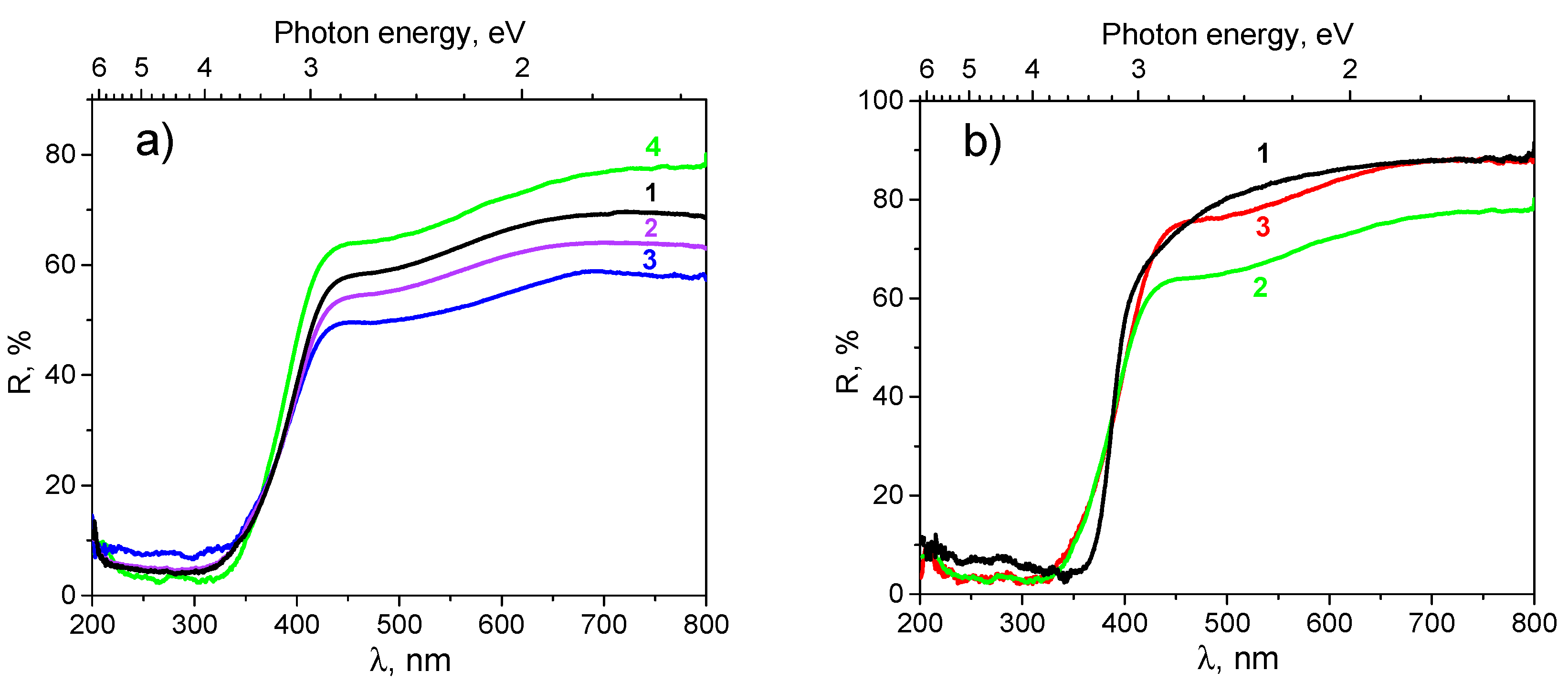
The region of sharp change of reflection (350 – 400 nm) obviously corresponds to the absorption edge of the glasses. Analysis of the shape of the spectra at the absorption edge, according to the widely used Kubelka-Munk theory and Tauc plot technique [48,49], allowed us to estimate the optical band gaps Eg for these glasses. The estimated values of Eg lie in 3.44 – 3.62 eV range (Table 1).
It is known that absorption in 200-400 nm range can be caused by molecular phosphate and molybdate groups, molybdenum and bismuth ions (see details in [33,34,35,50,51] and the text below). The wide absorption bands in 450 – 650 nm range (transitions in the forbidden zone) occur due to defects in the glass matrix. Some increase in absorption at the long-wavelength limit of the measurement range (700 – 800 nm) should be of the same nature.
As Figure 2a shows, the G5.69 glass has the lowest absorption in the visible light range (370 – 800 nm) and the highest absorption in the UV range (200 – 370 nm) among all glass samples studied (if we assume that light scattering for all samples is the same). This fact makes the G5.69 glass the most interesting for further elaboration of luminescent glass ceramics based on it.
In Figure 2b, the diffuse reflection spectra of G5.69 glass are compared with corresponding spectra of GC5.69 glass ceramics and Kbi(MoO4)2 polycrystalline powder. These data confirm the above-mentioned assumptions about the nature of absorption of the studied systems. At λ < 400 nm, the spectra of glass and glass ceramics practically coincide, while at λ > 400 nm, the reflection of the glass is much lower, although the shape of the spectra is preserved (Figure 2b, curves 2 and 3). Therefore, it can be assumed that in this region, the increase in diffuse reflection of the glass ceramics sample is due to light scattering on the Kbi(MoO4)2 micro/nanocrystals incorporated into the glass. The increase of absorption of crystals in 275 – 375 nm range may be due to an increase in the relative amount of bismuth ions and MoO42- groups compared to their amount in the glass and glass ceramics. At the same time, it can be seen that the crystals practically do not show a defect-related absorption band in 450 – 650 nm range. This result evidently follows from the expected lower defectiveness of the lattice structure of crystals compared to that of glass and glass ceramics.
3.1.3. Photoluminescence Spectroscopy
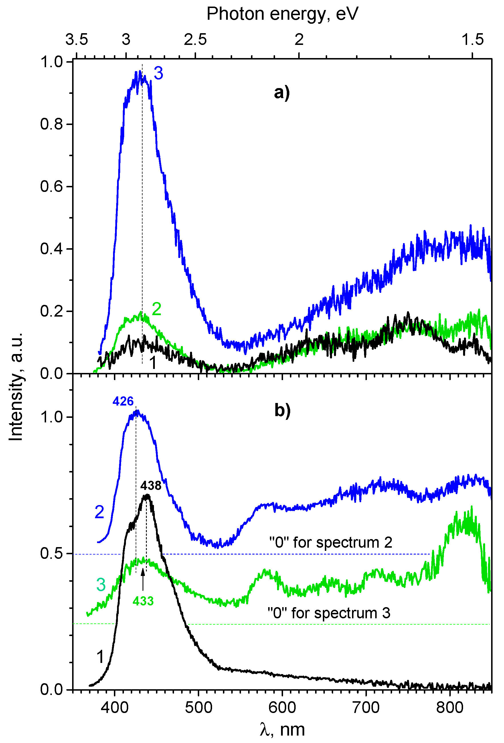
The studied glasses and glass ceramics, when excited in their absorption region, exhibit photoluminescence with intensity sufficient for analysing its spectral behaviour. The most intensive PL band with a maximum near 435 nm is located in the blue luminescence range 375 – 525 nm (below we refer this band as the “blue” PL). The spectral profile of this band is asymmetric, and therefore, it consists of at least two components. In addition to this band, the spectra also reveal a wide band extending from 550 to 850 nm (Figure 3), referred below as “yellow-red” PL. For G1 glass, four components with maxima λmax in the vicinity of 580, 635, 750, and 830 nm can be distinguished in this band (Figure 3a, curve 1). When moving from the glasses G1, G1.48 to glass G4.12, the total PL intensity increases by a factor of 4.24. However, the rate of such increase is different for the “blue” and “yellow-red” bands. While the “blue” band increases by ~ 8.4 times, the “yellow-red” band increases only by 2.9 times (see Table 1).
At the same time, the components of the “yellow-red” band are almost indistinguishable for the case of G4.12 glass sample (Figure 3a, curve 3). The absence of clear correlations in changes of intensity of the “blue” and “yellow-red” bands is evidence of their different origin. The same conclusion should be drawn regarding the origin of the components of “yellow-red” band, whose intensity in transition G1 ® G1.48 ® G4.12 also changes uncorrelated: here, the intensity of the long-wave components with λmax at 750 and 830 nm increases more strongly (Figure 3a). Thus, the origins of these components are different.
Figure 3.
The PL spectra of: (a) glass samples G1 (1), G1.48 (2), and G4.12 (3); (b) Kbi(MoO4)2 crystalline powder (1), G5.69 glass (2), and GC5.69 glass-ceramics (3); λex = 365 nm.
Figure 3.
The PL spectra of: (a) glass samples G1 (1), G1.48 (2), and G4.12 (3); (b) Kbi(MoO4)2 crystalline powder (1), G5.69 glass (2), and GC5.69 glass-ceramics (3); λex = 365 nm.
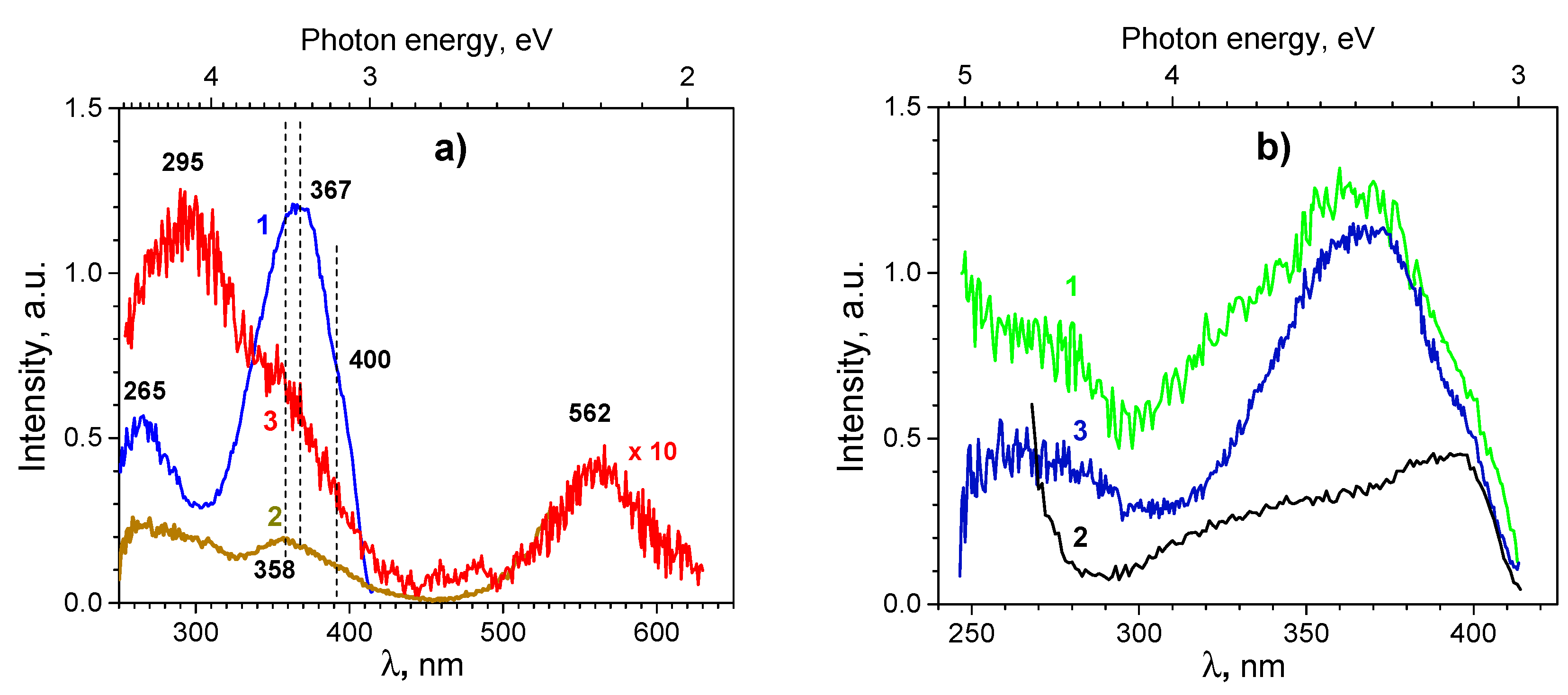
The “blue” PL is excited by short-wave UV light in a band with maximum around 265 nm and in the long-wave UV region, in a band with maximum around 367 nm (Figure 4a, curve 1). Both excitation bands likely are complex. The first one is a composition of at least two, and the second one (367 nm) of at least three components, of which the middle one has the highest intensity, and the other two look like side wings. It is easy to see that the excitation bands correspond to the features of diffuse reflection/absorption spectra described above.
Figure 4.
(a) PL excitation spectra of G4.12 glass measured at λem = 435 (1), 570 (2), and 650 nm (3). (b) PL excitation spectra of the KBi(MoO4)2 polycrystalline powder (1), G5.69 glass (2), and GC5.69 glass-ceramics (3); λem = 435 nm.
Figure 4.
(a) PL excitation spectra of G4.12 glass measured at λem = 435 (1), 570 (2), and 650 nm (3). (b) PL excitation spectra of the KBi(MoO4)2 polycrystalline powder (1), G5.69 glass (2), and GC5.69 glass-ceramics (3); λem = 435 nm.
The spectra of “blue” PL and its excitation for the systems studied here are consistent with the PL spectra of Bi3+ ions in various types of crystals and glasses [40,52,53].
Comparison of the “blue” PL spectra of glass with the recorded PL spectra of Kbi(MoO4)2 crystal confirms that the “blue” PL band should be associated with the luminescence of Bi3+ ions. It is well known that Bi atoms have the electronic configuration (Xe)4f145d106s26p3, whose outer (s, p) electrons can combine in various chemical compounds to form charge states 0, +1, +2, +3, and +5. In particular, Bi3+ ions have a 6s2 electronic configuration, which is quite sensitive to influence of the nearest surrounding. The ground state in this configuration is 1S0, and the excited states are 3P0, 3P1, 3P2, and 1P1 (in order of the energy increasing). According to the selection rules for electro-dipole transitions with light absorption, the 1S0 → 3P0 and 1S0 → 3P2 transitions are strictly prohibited. Therefore, the photoexcitation of Bi3+ ions usually occurs due to the 1S0 ® 3P1, 1P1 transitions. For example, for the glasses of composition xMoO3–30B2O3–(70–x)Bi2O3, transition 1S0 → 1P1 was associated with excitation band at 225 nm, whereas the bands at 300 and 365 nm were assigned to 1S0 ® 3P1 transition. The doubling of the latter transition was explained by the location of Bi3+ ions in positions with different structures of the nearest surrounding [57]. Accordingly, the luminescence of Bi3+ ions occurs due to 3P1 ® 1S0 radiative transition, which causes the noted spectral band of “blue” PL. The peak position of this band can lie between 425 and 570 nm, which is determined by the interaction of Bi3+ ions with the environment, namely the structure and symmetry of the latter.
The spectral characteristics of observed "blue" PL bands of glasses and KBi(MoO4)2 crystal are quite similar, so it should be assumed that the nearest surrounding of Bi3+ ions in the studied glasses and Kbi(MoO4)2 crystals is also similar. In Kbi(MoO4)2 crystals, bismuth ions are surrounded by 8 oxygen ions located at a distance 2.55 – 2.63 Å (average < d > ≈ 2.59 Å). These oxygen ions form the first coordination sphere of the bismuth ions, while the second sphere of the environment (at distances ~3.80 – 4.10 Å) contains 8 molybdenum ions, 4 oxygen ions and 4 positions that can be equally occupied by both bismuth and potassium ions [39,58]. Changes in the structure and composition of Bi3+ environment lead to changes in the spectral characteristics of their optical absorption and luminescence. Thus, the asymmetry of the “blue” PL band and the appearance of several bands in its excitation spectra can be attributed to the presence of Bi3+ ions in crystals and glasses, which are in a slightly different environment.
In the PL spectrum of Kbi(MoO4)2 crystal, one can also see a long-wavelength “tail” of low intensity extending from 500 to 800 nm (Figure 3b, curve 1). Its manifestation is associated with radiative transitions in defective molybdate groups and other defects of the crystal lattice, primarily with vacancies in the oxygen sublattice [39,40].
Taking into account the literature and our own data, we can confidently state that the “blue” PL band at 435 nm (Figure 3a) and the associated excitation bands at 265 and 367 nm (Figure 4a, curve 1) are caused by the excitation and emission processes in Bi3+ ions, which, similar to the case of Kbi(MoO4)2 crystals, are mainly surrounded by 8 oxygen O2- ions. It is obvious that the structure of the nearest surrounding of Bi3+ ions can change when the glass composition changes. As Figure 3 and Figure 4 show, the peak position of the “blue” PL band insignificantly depends on the glass composition, however, the side wings of the band differ, resulting in a change in the band shape. This observation may be an indication of the fact that the distance between the Bi3+ and the nearest oxygen ions and the structure in the first coordination sphere do not change, while the second and third spheres undergo changes.
The spectra of studied glasses also show additional, if compared to the case of Kbi(MoO4)2 crystals, PL (Figure 3) and PL excitation bands (Figure 4a, curves 2 and 3). The spectrum of additional PL is located in 550 – 850 nm region, longer than the spectrum of the “blue” PL of Bi3+, and therefore here and below this additional PL will be referenced as “yellow-red”. The spectrum of the “yellow-red” luminescence is formed by several components, the peak positions of which can be roughly defined as 580 (a weakly expressed band), 635, 750, and 830 nm. In the excitation spectra of the “yellow-red” PL, in addition to the bands inherent in the excitation of Bi3+ ions, bands with maxima at approximately 295, 460, 480, and 560 nm are observed. The relative intensity of these bands depends on registration wavelength λem. When registering at λem= 570 nm (Figure 4a, curve 2), a band with a maximum in the vicinity of 300 nm is clearly visible in the spectrum. At such registration wavelength, the excitation band of the “blue” PL (367 nm) is “deformed” compared to curve 1 in Figure 4a, and its maximum is shifted to 358 nm, i.e., towards the above-mentioned short-wavelengh wing. At λem = 650 nm, the band at 295 nm already dominates in the excitation spectrum, and in addition to it, the peaks at 458 and 483 nm and a relatively wide band at 562 nm are observed (Figure 4a, curve 3).
Similar spectral and luminescent manifestations were observed earlier for bismuth-containing glasses and were associated with the absorption and luminescence of bismuth ions in different charges existing in an oxygen environment of different structure and composition. Earlier, it was also emphasized that the formation of several bismuth ions of different charge states could be the result of reversible auto-thermal reduction of Bi3+ ions down to the Bi0 state, which can occur during melting, or one of the transformations of intermediate valence states: Bi3 + ↔ Bi2+ ↔ Bi+ ↔ Bi0 [57,59,60,61]. Therefore, the set of luminesce bands was associated with electronic transitions in ions/atoms/groups such as Bi5+, Bi2+, Bi+, BiO, Bi2-/Bi22-, Bi2-/Bi2, Bi and their clusters [59,60,61,62,63]. Table 2 shows some literature data on the assignment of luminescence bands and there excitation in bismuth-containing glasses.
Table 2.
Assignments of photoluminescence (PL) and PL excitation (PLE) bands in bismuth-containing glasses to specific transitions (literature data).
Table 2.
Assignments of photoluminescence (PL) and PL excitation (PLE) bands in bismuth-containing glasses to specific transitions (literature data).
| Glass composition | Band location: region (λmax), nm |
Band assignments and comments | Refs. | |
|---|---|---|---|---|
| PL | PLE | |||
| 33SrO-67B2O3-1Bi2O3 | (560) | 200 – 230 (218) | 1) Transitions in Bi3+ ions: PLE bands at 218, 344, and 355 nm; 2) 2P3/2 ↔ 2P1/2 transitions in Bi2+ ions: PLE band at 480 nm and PL band at 690 nm. Relative contribution of these bands into overall PL or PLE spectra depends on the ratio between glass-forming B2O3 and network modifier SrO oxides. |
[59,60,61,62] |
| 300 – 400 (344) | ||||
| 400 – 550 (480) | ||||
| (690) |
(350) | |||
| (480) | ||||
| MO3-B2O3-CeO2-Bi2O3 (M= Mo or W) | (600) | (300) | PL and PLE bands ascribed to 2P3/2 ↔ 2P1/2 transitions in Bi2+ ions. |
[35] |
| (610) | ||||
| xMoO3–30B2O3–(70–x)Bi2O3 (x = 0, 2.5, 5, 7.5, and 10 in mol%) | (600) | (300) | [57] | |
| (620) | ||||
| (95−x) SiO2·xSrO·5Al2O3·2Bi2O3 (x = 30, 35, 40, 45, 50, in mol%) | (640) | (532) | [52] | |
| MO-B2O3-Bi2O3 (M=Ca, Sr, Ba) | (660) | (470) | 1) 2P3/2 ↔ 2P1/2 transitions in Bi2+ ions: PLE band at 470 nm and PL band at 660 nm; 2) The infrared emission peak possibly comes from Bi ions in low valence state. |
[59,62] |
| (1300) | (808) | |||
| 23B2O3–5ZnO–72Bi2O3–xCuO | (804) | (530) |
3P2 → 3P0 transitions in Bi+ ions: PL band; 3P0 → 1S0 transitions in Bi+ ions: PLE band |
[60] |
According to the data collected in Table 2, it can be stated that decreasing of the charge state of bismuth ions (Bi3+® Bi2+, Bi+) leads to red-shifting of the absorption and luminescence bands of Bi-related centers. Oxygen coordination of bismuth is another factor that probably influences the positions of these bands. In particular, it is assumed that IR luminescence (1000 to 1600 nm) in bismuth-containing glasses can be attributed to the X22P3/2 ® X12P1/2 radiation transition in the BiO groups [52], as Bi2O3 can be partially converted into the noted molecular species at high temperature.
The picture of luminescence processes described above becomes more complicated for glasses containing molybdate molecular groups and molybdenum ions. As a rule, molybdate groups in oxide glasses, if they form a network, exist in the form of MoO42- tetrahedra. The Mo5+ ions can also exist in such systems in small quantities (up to 1 – 2 %) [64]. The weak intensity of PL band at 850 nm was attributed to emission of the Mo3+ ions in the lead borate glasses (P2O5)-(Li2O)-(CaO)-(Al2O3)-(MoO3) [65], although an earlier work [51] stated that the peak of the PL band of Mo3+ ions should be in the vicinity of 970 nm.
In bismuth-containing glasses of the MoO3–B2O3–Bi2O3 type, the absorption peaks near 360, 450 and 460 nm can be related to Mo3+ ions, while the absorption peaks in 360 – 380 and 710 – 780 nm ranges can be associated with the Mo5+ ions, and the Mo4+ ions can cause an absorption band near 550 nm [53]). At 300 nm excitation, these glasses show a “blue” PL with a maximum at 460 nm, and glasses with MoO3 content above 7.5 M show PL bands with maxima at 600 and 620 nm, the intensity of which increased with increasing molybdenum content. Due to the overlap of emission and absorption bands of Mo and Bi ions in such systems, excitation energy transfer between Mo and Bi ions can occur. This phenomenon also affects and complicates luminescence processes in the glasses under study.
In addition to the noted above, in molybdate glasses containing bismuth, mutual redox reactions between Bi and Mo can occur. These reactions result in the partial oxidation of Mo3+ and Mo5+ into Mo6+ ions (the latter do not exhibit noticeable luminescence) and the simultaneous partial reduction of Bi3+ into Bi2+ ions [35 and elsewhere]. These transformations should quench the intensity of the “blue” fluorescence of Mo3+ and Bi3+ ions and, conversely, promote the growth of the intensity of the “yellow-red” luminescence of bismuth ions with increasing Bi2O3 content. It is easy to see that this is exactly the behavior of the spectral and luminescent characteristics of the glasses studied here. Indeed, Table 1 shows that for the first three samples, the total PL intensity (ITot), the intensity of the “blue” (IBlue) and the “yellow-red” PL (IYR) increase by 4.2, 8.4 and 2.9 times, respectively, with a 4.12-fold increase of Bi2O3 content. As can be seen, the increase in PL (ITot) corresponds to an increase in the content of the bismuth-oxide component of the glass, which confirms association of PL with bismuth ions. With a further increase in Bi2O3 content by a factor of 1.38, up to 5.69 M, ITot increases by a factor of 1.15, IYR by a factor of 1.39, and the intensity of the blue PL even decreases by a factor of 0.9. The latter changes are manifestations of the above-mentioned transformations of bismuth ions towards a decrease in their charge and, accordingly, transformation of the “blue” PL spectra into the bands of “red” and near-IR emission.
3.2. Part 2. Insight from Interphase Layers
Results of experiments presented below were used in computational studies of the interphase layers.
3.2.1. FTIR Spectroscopy Data
The FTIR spectroscopy of studied glasses (Figure 5) provided information on active vibrational system of the investigated materials, which clarified the sets of molecular groups (fragments) to be taken into account for adequate computational modelling.
Figure 5.
FTIR spectra of G1 (1), G1.48 (2), G4.12 (3) and G5.69 (4) glasses.
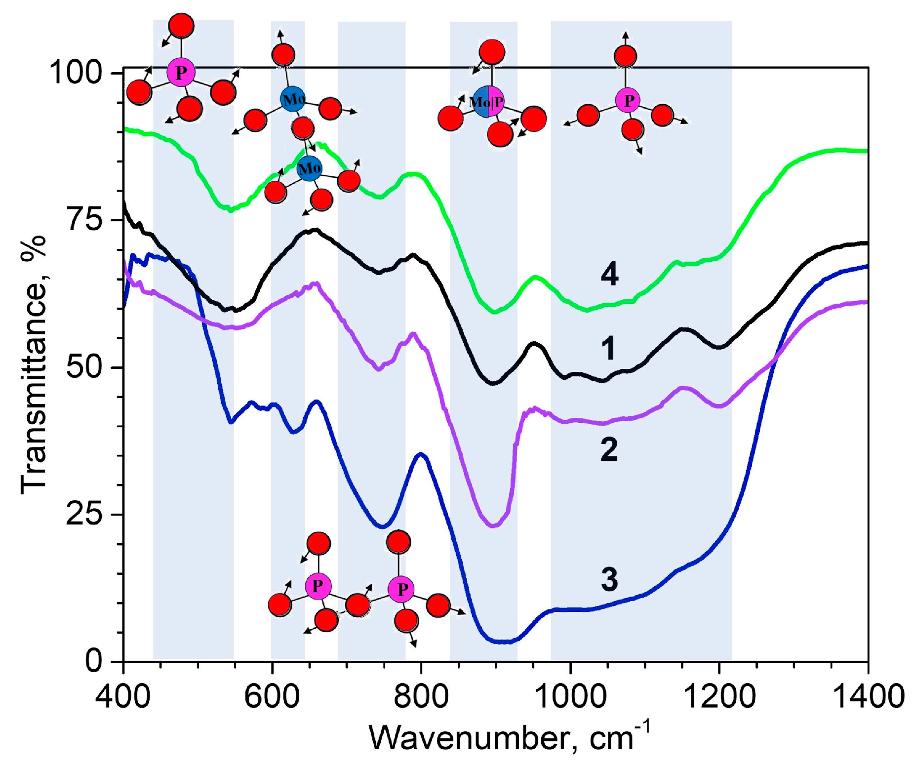
The FTIR spectra show a set of characteristic bands which have been expected for phosphate-molybdate glasses (Figure 5). A wide band with a maximum near 540 – 550 cm-1 corresponds to O–P–O bending vibration mode [66,67]. The absorption band at 640 cm-1 found for glasses with the highest content of MoO3 (36 – 46 %) has been attributed to MoO42- and Mo2O72- bending vibration modes [68]. The bands observed near 745 cm-1 were attributed to stretching modes of the bridging oxygen atoms (P–O–P) in P2O7, P3O9, P3O10, P4O13 chains. This band is shifted to higher frequencies, from 739 to 752 cm-1 with the MoO3 content increase. The complex bands located around 900 – 1204 cm-1 are attributed to symmetric stretching of non-bridging oxygen in PO43- tetrahedra [67], and asymmetric stretching vibration of P–O–P in the PO2- groups [69]. The band observed at 1222 cm-1 is assigned to symmetric stretching vibrations of PO3- groups. The band with low intensity at 1245 cm-1 is assigned to P=O asymmetric stretching vibration of phosphate tetrahedra located in the chains.
It should be noted that Intensity of various vibration bands of phosphate structures Is Increased with increase of MoO3 content. Consequently, molybdenum oxide as a glass modifier increases the number of non-bridging oxygens in the phosphate network and acts as ionic cross-linker among phosphate groups lowering the polymerization level of phosphate nets.
In accordance with the results of IR spectroscopy and literature data, the unit cells used in calculations of glasses and crystal/glass interfaces were initially filled (see details in Sec. 2.3) with molecular groups РО4, P3O9, P3O10, P4O13, MoO4, Mo2O7, as well as individual K and Bi atoms. The ratio between the numbers of molecular groups was chosen so that the XRD spectra and density of the modelled structures, after MD optimization were as close as possible to the experimental data. The ratios of the number of molecular groups used for initial filling of the cells are given in Table S1.
3.2.2. XRD and Density: Experimental and Calculated Data
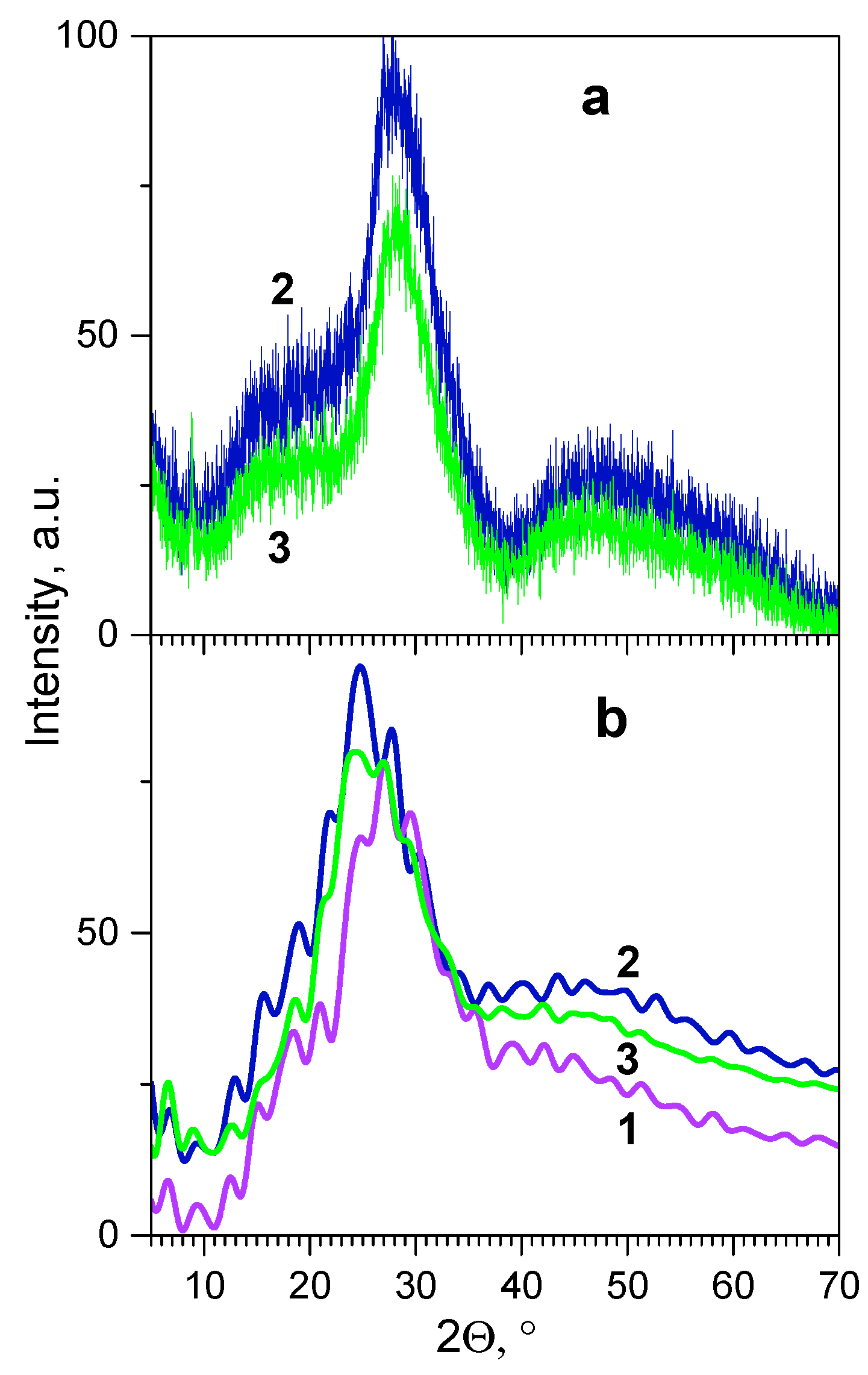
Comparison of the calculated and experimentally measured XRD patterns (Figure 6) and density (Figure 7) shows a fairly good compliance between the calculation results and experimental data. Indeed, Figure 6 shows that the calculated XRD patterns reproduce well such features of the experimental diffractograms as the main peak in the 25-30° region of 2Θ, an additional shoulder in 10-22° region, and the general profile of the curve above 35°.
Figure 6.
Experimental (a) and calculated (b) XRD patterns for the studied glasses: G1.48 (1), G4.12 (2), and G5.69 (3).
Figure 6.
Experimental (a) and calculated (b) XRD patterns for the studied glasses: G1.48 (1), G4.12 (2), and G5.69 (3).
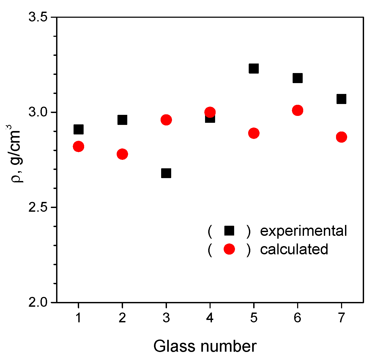
The data on the density of the samples (Figure 7) show that, despite a certain error, the calculations satisfactorily reproduce the trends in the density of studied glasses. This compliance of the calculation results with experimental data evidences the adequacy of chosen approximations, parameters and scheme of MD calculations.
Figure 7.
Experimental and calculated density versus glass composition number (see Table S1).
Figure 7.
Experimental and calculated density versus glass composition number (see Table S1).
3.2.3. Determination of Thickness and Chemical Composition of Interphase Region
As a result of applying the MD procedure to the interphase cell, part of which contained crystal and the other part glass, a significant mixing (mutual diffusion) of glass and crystal atoms occurred (an example of such mixed structure is presented in SM, Figure S1b). The degree of mixing can be quantitatively characterized by the calculated concentration profiles of chemical elements. Note that the part of the cell corresponding to the z-coordinate values from 0 to ~18 Å was initially filled with Kbi(MoO4)2 crystal atoms, while the rest of the cell was filled with the glass of composition # 4 (G4.12). Atomic coordinates of the crystal layer located below the initial crystal/glass boundary (z in range from 0 to ~4 Å) were “frozen” at all steps of MD calculation scheme (see Sec. 2.3).
Figure 8 shows the calculated concentration profiles of chemical elements calculated along the normal to the “Kbi(MoO4)2/glass” interface, i.e. along the z-coordinate. Concentration profiles were calculated for two glass compositions, #4 (G4.12) and #7 (G5.69), after initial filling (black curves in Figure 8) and after applying the MD calculation procedure (red curves). In order to obtain a sufficient statistical base, the curves shown in the figure were obtained by averaging the corresponding data over 10 different structures. The vertical dashed line indicates the projection of the conditional crystal/glass boundary (interface plane) that existed at the initial filling stage (the plane corresponds to z≈ 17 ± 0.5 Å).
Figure 8.
Concentration profiles of constituent elements of KBi(MoO4)2@glass interphase cell calculated along the normal to initial boundary for glasses G5.69 (a) and G4.12 (b): after initial filling (black curves) and after the MD calculations (red curves). The initial crystal/glass boundary is marked with a vertical dashed line.
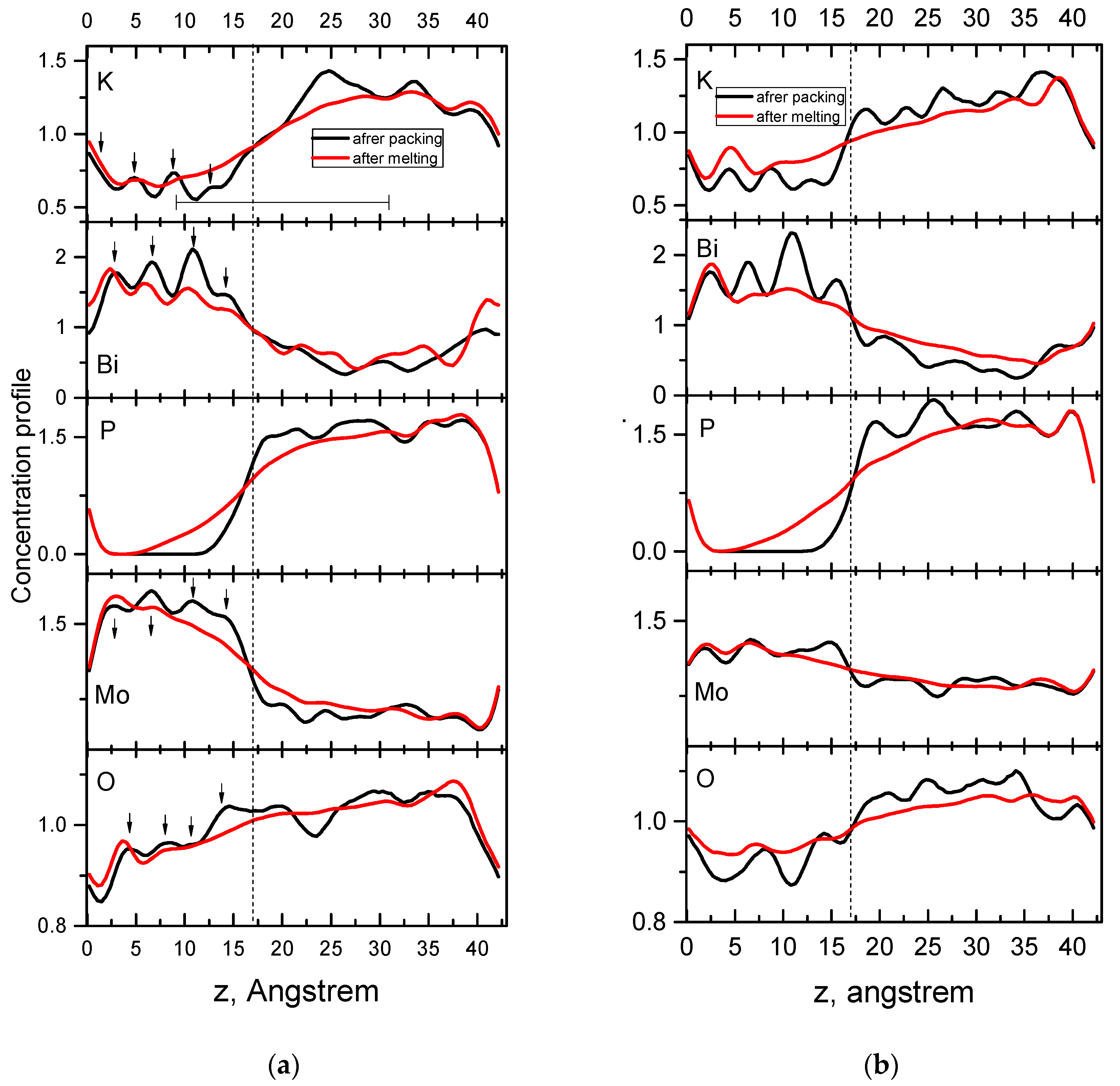
As Figure 8 shows, in the case of G5.69 glass (left part of the figure), the initial concentration profiles in the crystal region (black curves) are characterized by a set of peaks and dips with a clear periodicity along the z coordinate. This behavior of the profiles is an obvious consequence of the crystal atomic structure periodicity, namely, the existence of layers of potassium and bismuth ions and molybdate groups in it. The local concentration maxima (indicated by vertical arrows in the figure) obviously correspond to position of the layer of a particular element kind.
After the MD calculation procedure, the crystal and glass atoms mix to form an interphase layer. The width (thickness) of the latter can be estimated as the range z, where the change in the concentration profiles "before" and "after" the MD procedure is significant. This assessment is most indicative of the phosphorus profile, since its concentration in the KBi(MoO4)2 crystal region is zero. As a result, according to the phosphorus profile, the interphase lies within the range of z from 7.5 to 22.5 Å. It can be seen that significant changes in the concentration of all other elements also occur in this range (the range is indicated by a horizontal line in the left top part of Figure 8). Thus, according to results of the calculations, the thickness of the interphase layer in the KBi(MoO4)2@G5.69 glass ceramics should be estimated at ~15 Å.
As the left part of Figure 8 shows, the concentration curves for K and Mo reveal significant mixing of these elements, and the peaks corresponding to the outermost layers of the crystal practically disappear after the MD procedure. In contrast, the situation for Bi is somewhat different: the Bi layers in the crystal region remain clearly visible in the concentration curve even after the MD procedure. This fact indicates that bismuth ions move relatively weakly (compared to other elements in the crystal) towards the glass.
Phosphorus atoms, on the contrary, diffuse from the glass to the crystal (corresponding concentration curve decreases monotonically in the glass-to-crystal direction). The change in the oxygen concentration curves, although also noticeable, lies within the statistical error of the averaging, since the oxygen content of the crystal and glass G5.69 was approximately the same at the stage of initial filling.
As the data in the right part of Figure 8 show, the concentration profiles of KBi(MoO4)2@G4.12 interphase are generally similar to those described above and lead to similar conclusions, in particular, regarding the thickness of the interfacial layer. However, the concentration profile of bismuth is an exception. As can be seen from the figure, in the case of the G4.12 glass, the three peaks of the Bi concentration curve in the KBi(MoO4)2 crystal, closest to the initial boundary, disappear after the MD procedure. This means that during formation of KBi(MoO4)2@G4.12 interphase, deeper layers of bismuth atoms of the crystal are disordered if compared with KBi(MoO4)2@G5.69 case. This is probably due to the higher (almost twice) content of molybdate groups in G4.12 glass compared to G5.69 one (see Table S1). Thus, the increase in the content of molybdate groups in the glass enhances the diffusion of bismuth cations from the KBi(MoO4)2 crystal to phosphate-molybdate glass.
This conclusion is consistent with the change in the composition of the interphase layer compared to the composition of the glass phase (see below). Concentration profiles of the KBi(MoO4)2@G4.12 interphase cell (Figure 8, right) show that in the z-coordinate region between ~10 and ~30 Å there is a significant redistribution of chemical element concentrations relative to the corresponding concentrations in the composite components - KBi(MoO4)2 crystal and G4.12 glass. Right this region with a thickness of ~20 Å can be considered the interphase layer of the composite system KBi(MoO4)2@G4.12.
Similar results regarding the thickness of the interphase layer were obtained for composite glass-ceramic systems with other compositions. Thus, according to the calculation results, the thickness of the interphase layers in the "KBi(MoO4)2@(xP2O5-yMoO3-zBi2O3-(1-x-y-z)K2O) glass-ceramics can be estimated as ~1.5-2.0 nm.
By counting the number of atoms in the noted part of the interphase cell (between 10 and 30 Å along the z-axis), we found that the chemical composition of the interphase region approximates the formula K12P6Mo10Bi5O61. If we compare this formula with composition of the glass component (K18P13Mo5Bi3O61, see SM, Table S1), significant changes become evident. In particular, a twofold increase in the molybdenum content in the interphase is accompanied by a 1.67-fold increase in the bismuth content; the number of oxygen atoms does not change, and the potassium and phosphorus content decreases by 1.5 and 2.17 times, respectively. Thus, it can be argued that in the interphase region, the number of oxygen atoms near molybdenum and bismuth ions should decrease compared to the case of the glass medium. In the case of interphase of KBi(MoO4)2@G5.69 system, the DFT-based geometry optimizations were carried out with use of rather small cells (12x12x12 Å). These cells were filled with the same fragments as in the G5.69 glass case (see SM, Table S1), however with different amounts: (P3O9) - 2 units, (MoO4) - 6 units, (Mo2O7) - 2 units, K - 12 units, and Bi - 5 units. The chosen ratio of fragments corresponds to the chemical composition of the interphase determined above - (K12P6Mo10Bi5O61). The results of geometric optimization of structures are analyzed below.
3.2.4. Analysis of Structure of the Nearest Surrounding of Bismuth Cations
Using results of the structural geometry optimizations by the DFT method, we analyzed the composition and structure of the nearest oxygen surrounding of bismuth cations located in different spatial regions of KBi(MoO4)2@G5.69 system. For this purpose, we estimated content of different types of ВiOn polyhedra (with coordination number n = 2, 3, 4, ..., 8) in the crystal, glass, and interphase of this glass-ceramic system using SHAPE utility program [70]. The analysis was applied to 8 geometry-optimized structures of G5.69 glass and KBi(MoO4)2@G5.69 interphase with the subsequent statistical averaging of the results. For the case of the KBi(MoO4)2 crystal, the analysis was performed using its crystal structure taken from literature [71]. The analysis took into account all oxygen atoms at a distance of less than 3.2 Å from bismuth atoms.
Results of analysis by SHAPE utility are summarized in Table 3. Among other structural characteristics, the Table contains the calculated parameters S, which characterize degree of deviation of the polyhedron from the ideal one. The value of S is calculated as a measure of deviation from the ideal polyhedron of a certain dimension, which is expressed through the standard deviation of the lengths of each of the B-O bonds. The parameter is normalized to 100% so that a value of S = 0 corresponds to a complete coincidence of the structure with an ideal polyhedron of a certain dimension and symmetry, and a value of S = 100% is not achieved in principle [72]. Thus, the smaller is the value of S, the closer the structure is to the ideal polyhedron of the corresponding dimension and symmetry.
Table 3.
Characteristics of the oxygen surrounding of bismuth atoms in the crystal, glass and interphase of KBi(MoO4)2@G5.69 system.
Table 3.
Characteristics of the oxygen surrounding of bismuth atoms in the crystal, glass and interphase of KBi(MoO4)2@G5.69 system.
| Types of polyhedra |
KBi(MoO4)2 crystal | Glass G5.69 | Interphase | |||
|---|---|---|---|---|---|---|
| Content, %. | ΔS 1 | Content, %. | ΔS | Content, %. | ΔS | |
| BiO2+ BiO3 | - | - | - | - | 5.3 | - |
| BiO4 | - | - | 4.2 | 0.697 | 15.8 | 0.674-7.591 |
| BiO5 | - | - | 50.0 | 0.433-14.867 | 50.0 | 0.339-12.064 |
| BiO6 | - | - | 41.6 | 1.263-11.995 | 28.9 | 1.503-24.535 |
| BiO7 | - | - | 4.2 | 2.974 | - | - |
| BiO8 | 100 | 0.481 | - | - | - | - |
1 ΔS is the numerical range in which fall the S values calculated for all polyhedra of corresponding system.
For convenience, in calculations of the S parameter the following approximations were used. If Bi cation is surrounded by 5 oxygen atoms, then it is considered to be an octahedron with an oxygen vacancy - the symmetry of the position in such an ideal "Vacant octahedron" is C4v. If Bi has 6 oxygens in its surrounding, then it is treated as "Octahedron" of symmetry Oh. Deviations from the octahedron were considered only for both 5- and 6-coordinated bismuth atoms.
Results of analysis show that in KBi(MoO4)2 crystal, all bismuth atoms are surrounded by 8 oxygen atoms, which form distorted triangular dodecahedrons (point group of symmetry of bismuth ion is D2d). In contrast, for glass, there is a significant decrease in the coordination number of the oxygen environment of bismuth atoms. The ВіО8 polyhedra are absent there at all, and the most common form of oxygen surroundings are ВіО5 and ВіО6 polyhedra (see Table 3). In the case of interphase, the coordination of bismuth is even simpler: the number of polyhedra of BiO6 decreases by about half compared to glass, the number of BiO4 increases fourfold, and the simplest structures of bismuth surrounding appear - BiO3 and BiO2. Degree of deviation from an ideal form of BiO6 in the interphase (see the corresponding values of ΔS in the Table 3) is obviously higher than for such polyhedra in the glass.
Thus, according to the results of our analysis, the structure of the nearest oxygen surrounding of bismuth in the KBi(MoO4)2 crystal (only BiO8 polyhedra) is fundamentally different from the corresponding structure of bismuth environment in glass (mainly BiO5 and BiO6 polyhedra), and in the interphase regions of glass ceramics. In the latter, BiO2 and BiO3 structures appear and the number of BiO4 increases.
4. Concluding Remarks
It is worth to compare results of experimental studies of glass systems presented in the first part of this paper with results of computational studies of glass-ceramic systems presented in the second part. From this comparison, it can be seen that an increase in the bismuth oxide content in the glass, as well as formation of an interphase layer in glass ceramics, result in an increase in the number of bismuth ions coordinated by (bonded with) fewer oxygen atoms. Consequently, some peculiarities of spectral/luminescent properties should be common for both studied glasses and glass ceramics.
For real glass-ceramic systems with a sufficient total volume of interphase regions, changes in the quantitative composition of different types of bismuth polyhedra can be observed experimentally. Indeed, Figure 2 shows that in the 450 – 650 nm region, the reflection spectrum of GC5.69 glass-ceramics differs significantly from the reflection spectra of both G5.69 glass and the KBi(MoO4)2 crystal. This difference can be attributed to the influence of interphase regions.
The luminescence manifestations of interphase layers are more noticeable. So, in the excitation spectra of the "blue" PL of glass (Figure 4, curve 2), in contrast to the excitation spectrum of such PL in crystals (Figure 4, curve 1), the main band is observed at 367 nm (see Figure 3). The same band dominates the excitation spectrum of glass-ceramics (Figure 4, curve 3), but here the contribution of bands in the 300 – 350 and 350 – 425 nm regions, which are characteristic of crystals, increases significantly. We also attributed these differences to the appearance of interphase layers in the composition of GC5.69 glass ceramics.
Regarding the manifestation of these layers in the PL spectra of the glass ceramics, it should be emphasized that according to data in Table 1, the "yellow-red" PL band increases by a factor of 1.55 compared to the "blue" PL band in G4.12 → G5.69 transition. The relative intensity of IYR/IBlue is 1.73. Comparison of the PL spectra characteristics of G5.69 glass and GC5.69 glass ceramics shows that G5.69 → GC5.69 transition is accompanied by an increase in the relative intensity of the "yellow-red" PL: IYR/IBlue increases from 1.73 to 1.96. This increase in IYR/IBlue, as can be seen from Figure 2, is mainly due to the longest-wavelength components of the "yellow-red" PL in the region of 700 – 850 nm. It has already been shown above (Part 1) that such changes in the spectra of glass are due to an increase in the contribution of bismuth ions with low charge and low coordination with oxygen atoms. Thus, the described luminescence manifestations confirm the influence of interphase layers on the properties of the studied glass-ceramic samples.
5. Conclusions
The properties of a set of glasses of the xP2O5-yMoO3-zBi2O3-(1-x-y-z)K2O system (where, x – in 23.01 – 40.31; y - in 13.55 – 46.02; z - in 1.00 – 5.69 range) and based on them crystal@glass ceramics where the crystal component is luminescent crystalline particles KBi(MoO4)2 have been produced and studied by experimental and theoretical methods.
It has been shown that the optical absorption and photoluminescence characteristics of such systems are largely determined by content of Bi2O3 and MoO3 oxides in the initial charge, and by content bismuth ions in different charge states which exist in the produced glass and glass ceramics.
In particular, the "blue" photoluminescence (spectral range 375 – 550 nm) of both glasses and glass ceramics originates from radiative transitions 3P1 ® 1S0 in bismuth ions Bi3+. The "Yellow-red" PL (spectral range 550 – 850 nm) should be mainly associated with the luminescence of bismuth ions in lower charge states – Bi2+, Bi+ and Bi0, and therefore it should be assumed that the increasing contribution of "yellow-red" PL to the total luminescence spectrum occurs due to an increase in the number of such lower-charge ions.
In glass-ceramics based on the xP2O5-yMoO3-zBi2O3-(1-x-y-z)K2O glass matrix and crystals KBi(MoO4)2, interphase layers are formed between the glass and crystal phases, the thickness of which is estimated to be 1.5 – 2.0 nm. According to theoretical results, the structure and composition of the interphase layers differ from those of both the glass and crystal components. In particular, if compared to the case of glass, content of bismuth and molybdenum in the interphase layer increases by 1.7 and 2 times respectively, and the content of potassium and phosphorus decreases by 1.5 and 2.17 times respectively, whereas content of oxygen is almost unchanged.
This decrease in the number of oxygen atoms in the nearest surrounding of bismuth ions in the interphase region is accompanied by changes in the spectra of optical absorption and PL / PL excitation, which allows to use these changes for spectral probing of the formation and presence of interphase layers.
Supplementary Materials
The following supporting information can be downloaded at: Preprints.org, Procedure of atomic structure modeling, Figure S1: Periodic cell constructed for interphase of KBi(MoO4)2@G5.69 system: initially filled and after MD calculations; Figure S2: An example 12x12x12 Å periodic cell of G5.69 glass, used in the DFT-based geometry optimizations; Table S1: Chemical composition, experimental and calculated densities of synthesized and modeled samples of the P2O5 - MoO3-Bi2O3-K2O glass system; Table S2: Parameters of interatomic interaction used in MD calculations.
Author Contributions
Conceptualization, Y.H, V.C., and S.N.; methodology, Y.H., S.N., and A.S.; software, V.B., Y.Z.; validation, K.T., S.N. and Y.Z.; formal analysis, V.C.; investigation, Y.H., V.C., K.T., S.N.; resources, Y.Z.; data curation, V.B., and V.C.; writing—original draft preparation, Y.H., V.C., and S.N.; writing—review and editing, Y.H., K.T., A.S., Y.Z., and S.N.; visualization, Y.H., and V.C.; supervision, A.S. and S.N.; project administration, S.N.; funding acquisition, S.N. All authors have read and agreed to the published version of the manuscript.
Funding
This work has received funding through the EURIZON 3010 project which is funded by the European Union under grant agreement No. 871072.
Data Availability Statement
The original contributions presented in this study are included in the article and supplementary material. Further inquiries can be directed to the corresponding author.
Acknowledgments
Serhii Nedilko thanks the Polish Academy of Sciences for the possibility of the research stay and spectroscopy measurements at the Institute of Physics PAS, Warsaw, Poland during these difficult times for Ukraine.
Conflicts of Interest
The authors declare no conflicts of interest
References
- Benyounoussy, S.; Bih, L.; Muñoz, F.; Rubio-Marcos, F.; Bouari, A.E. Effect of the Na2O–Nb2O5–P2O5 glass additive on the structure, dielectric and energy storage performances of sodium niobate ceramics. Heliyon 2021, 7, e07113. [Google Scholar] [CrossRef] [PubMed]
- He, M.; Jia, J.; Zhao, J.; Qiao, X.; Du, J.; Fan, X. Glass-ceramic phosphors for solid state lighting: a review. Ceram. Int. 2021, 47, 2963–2980. [Google Scholar] [CrossRef]
- Wang, D.; Xu, X.; Zhao, J.; Zheng, T.; Guo, Y.; Lv, J. The effect of Nd3+-doped phosphor-in-glass on WLED. Opt. Mater. 2024, 153, 115552. [Google Scholar] [CrossRef]
- Zhang, R.; Shang, F.; Chen, G. NaLaMo2O8: Yb3+, Er3+ transparent glass ceramics: Up-conversion luminescence and temperature sensitivity property. Ceram. Int. 2022, 48, 16099–16107. [Google Scholar] [CrossRef]
- Xing, J.; Qin, L.; Tang, J.; Li, L.; Shang, F.; Chen, G. Enhanced upconversion luminescence and temperature sensing feature in NaBi(MoO4)2: Er3+, Yb3+ transparent glass ceramics. J. Non-Cryst. Solids 2022, 576, 121267. [Google Scholar] [CrossRef]
- Mubina, M. K.; Shailajha, S.; Sankaranarayanan, R.; Smily, S.T. Enriched biological and mechanical properties of boron doped SiO2-CaO-Na2O-P2O5 bioactive glass ceramics (BGC). J. Non-Cryst. Solids, 2021, 570, 121007. [Google Scholar] [CrossRef]
- Piatti, E.; Miola, M.; Verné, E. Tailoring of bioactive glass and glass-ceramics properties for in vitro and in vivo response optimization: a review. Biomater. Sci. 2024, 12, 4546–4589. [Google Scholar] [CrossRef]
- Fu, L.; Engqvist, H.; Xia, W. Glass–ceramics in dentistry: A review. Materials, 2020, 13, 1049. [Google Scholar] [CrossRef]
- Rodríguez-López, S.; Pascual, M.J. Sintering/crystallization and viscosity of sealing glass-ceramics. Crystals, 2021, 11, 737. [Google Scholar] [CrossRef]
- Ebrahium, M.M.; Abo-Mosallam, H.A.; Mahdy, E.A. Effect of K2WO4 on structure and properties of low melting glasses in K2O–Fe2O3–P2O5 system as sealing materials. Ceram. Int. 2024, 50, 941–949. [Google Scholar] [CrossRef]
- Swain, R.E.; Reifsnider, K.L.; Jayaraman, K.; El-Zein, M. Interface/interphase concepts in composite material systems. J. Thermoplast. Compos. Mater. 1990, 3, 13–23. [Google Scholar] [CrossRef]
- Nedilko, S.G. Interphases in luminescent oxide nanostructured glass-ceramics. J. Mater. Sci.: Mater. Electron. 2023, 34, 998. [Google Scholar] [CrossRef]
- Wan, T.; Wu, M.; Pan, Q.; Deng, L.; Zhang, H.; Huang, X.; et al. Regulating interfacial diffusion of nanocrystal-in-glass composites: Insights from atomistic simulation. J. Am. Ceram. Soc. 2024, 107, 5825–5840. [Google Scholar] [CrossRef]
- Bocker, C.; Rüssel, C.; Avramov, I. Transparent nano crystalline glass-ceramics by interface controlled crystallization. Int. J. Appl. Glass Sci. 2013, 4, 174–181. [Google Scholar] [CrossRef]
- Bhattacharya, S.; Acharya, A.; Das, A.S.; Bhattacharya, K.; Ghosh, C.K. Lithium ion conductivity in Li2O–P2O5–ZnO glass-ceramics. J. Alloys Compd. 2019, 786, 707–716. [Google Scholar] [CrossRef]
- Stabler, C.; Schliephake, D.; Heilmaier, M.; Rouxel, T.; Kleebe, H.J.; Narisawa, M.; et al. Influence of SiC/Silica and Carbon/Silica Interfaces on the high-temperature creep of silicon oxycarbide-based glass ceramics: A case study. Adv. Eng. Mater. 2019, 21, 1800596. [Google Scholar] [CrossRef]
- Huang, J.; Zhang, Y.; Ma, T.; Li, H.; Zhang, L. Correlation between dielectric breakdown strength and interface polarization in barium strontium titanate glass ceramics. Appl. Phys. Lett. 2010, 96, 042902. [Google Scholar] [CrossRef]
- Gorni, G.; Balda, R.; Fernández, J.; Iparraguirre, I.; Velázquez, J.J.; Castro, Y.; et al. Oxyfluoride glass–ceramic fibers doped with Nd3+: Structural and optical characterization. CrystEngComm, 2017, 19, 6620–6629. [Google Scholar] [CrossRef]
- Shyu, J.J.; Wu, C.H. Enhancement of photoluminescence intensity of sintered CaAlSiN3: Eu2+ red phosphor-bismuthate glass composites. Int. J. Appl. Ceram. Technol. 2023, 20, 3163–3170. [Google Scholar] [CrossRef]
- Li, L.; Mi, J.; Yong, Y.; Mao, B.; Shi, W. First-principles study on the lattice plane and termination dependence of the electronic properties of the NiO/CH3NH3PbI3 interfaces. J. Mater. Chem. C. 2018, 6, 8226–8233. [Google Scholar] [CrossRef]
- López-Caballero, P.; Ramallo-López, J.M.; Giovanetti, L.J.; Buceta, D.; Miret-Artés, S.; López-Quintela, M.A.; et al. Exploring the properties of Ag5–TiO2 interfaces: stable surface polaron formation, UV-Vis optical response, and CO2 photoactivation. J. Mater. Chem. A. 2020, 8, 6842–6853. [Google Scholar] [CrossRef]
- Schulzendorf, M.; Hinaut, A.; Kisiel, M.; Jöhr, R.; Pawlak, R.; Restuccia, P.; et al. Altering the properties of graphene on Cu (111) by intercalation of potassium bromide. ACS Nano. 2019, 13, 5485–5492. [Google Scholar] [CrossRef] [PubMed]
- Chung, W.J.; Nam, Y.H. A review on phosphor in glass as a high power LED color converter. ECS J. Solid State Sci. Technol. 2020, 9, 016010. [Google Scholar] [CrossRef]
- Smith, B.; Akimov, A.V. Modeling nonadiabatic dynamics in condensed matter materials: some recent advances and applications. J. Phys.: Condens. Matter. 2020, 32, 073001. [Google Scholar] [CrossRef] [PubMed]
- Ottoboni, F.S.; Poirier, G.; Cassanjes, F.C.; Messaddeq, Y.; Ribeiro, S.J. Crystallization study of molybdate phosphate glasses by thermal analysis. J. Non-Cryst. Solids. 2009, 355, 2279–2284. [Google Scholar] [CrossRef]
- Zhao, Y.; Du, J.; Cao, X.; Zhang, C.; Xu, G.; Qiao, X.; et, l. A modified random network model for P2O5–Na2O–Al2O3–SiO2 glass studied by molecular dynamics simulations. RSC Adv. 2021, 11, 7025–7036. [Google Scholar] [CrossRef]
- Sun, H.; Yang, J.; Zhang, R. Composition engineering on the structure and transport properties of CaO–SiO2–P2O5 system: A computational insight. Metall. Material. Trans. B. 2024, 55, 1812–1829. [Google Scholar] [CrossRef]
- Sun, K.H. Fundamental condition of glass formation. J. Am. Ceram. Soc. 1947, 30, 277–281. [Google Scholar] [CrossRef]
- Hashimoto, H.; Onodera, Y.; Tahara, S.; Kohara, S.; Yazawa, K.; Segawa, H.; et al. Structure of alumina glass. Sci. Rep. 2022, 12, 516. [Google Scholar] [CrossRef]
- Brow, R.K.; Alam, T.M.; Tallant, D.R.; Kirkpatrick, R.J. Spectroscopic studies on the structures of phosphate sealing glasses. MRS Bull. 1998, 23, 63–67. [Google Scholar] [CrossRef]
- Dan, H.K.; Phan, A.L.; Ty, N.M.; Zhou, D.; Qiu, J. Optical bandgaps and visible/near-infrared emissions of Bin+-doped (n= 1, 2, and 3) fluoroaluminosilicate glasses via Ag+-K+ ions exchange process. Opt. Mater. 2021, 112, 110762. [Google Scholar] [CrossRef]
- Thabit, H.A.; Sayyed, M.I. , Es-soufi, H.; Bafaqeer, A.; Ismail, A.K. Insights into the influence of Bi2O3 on the structural and optical characteristics of novel Bi2O3–B2O3–TeO2–MgO–PbO glasses. Opt. Quantum Electron. 2024, 56, 332. [Google Scholar] [CrossRef]
- Na, Y.H.; Kim, N.J.; Im, S.H.; Cha, J.M.; Ryu, B.K. Effect of Bi2O3 on structure and properties of zinc bismuth phosphate glass. J. Ceram. Soc. Japan. 2009, 117, P–1273. [Google Scholar] [CrossRef]
- Kitamura, N.; Fukumi, K.; Nakamura, J.; Hidaka, T.; Hashima, H.; Mayumi, Y.; Nishii, J. Optical properties of zinc bismuth phosphate glass. Mater. Sci. Eng.: B. 2009, 161, 91–95. [Google Scholar] [CrossRef]
- Abo-Naf, S.M.; Abdel-Hameed, S.A.M.; Fayad, A.M.; Marzouk, M.A.; Hamdy, Y.M. Photoluminescence behavior of MO3-B2O3-CeO2-Bi2O3 (M= Mo or W) glasses and their counterparts nano-glass-ceramics. Ceram. Int. 2018, 44, 21800–21809. [Google Scholar] [CrossRef]
- Cui, J.; Sun, X.Y.; Wen, Y.; Chen, R.; Yu, M.; Du, W.; Xiao, Z. Cyan luminescence from Bi ions-doped borosilicate glass induced by the gradual substitution of MO (M= Ca, Sr, Ba). Opt. Mater. 2023, 144. [Google Scholar] [CrossRef]
- Terebilenko, K.; Alekseev, O.; Lazarenko, M.; Nedilko, S.G.; Slobodyanik, M.; Boyko, V.; Chornii, V. Luminescent Bi-containing Phosphate-Molybdate Glass-Ceramics. In Proceedings of the 2020 IEEE 10th International Conference Nanomaterials: Applications & Properties (NAP), Sumy, Ukraine, 9-13 November 2020. pp. 01–1. [CrossRef]
- Chornii, V.; Boyko, V.; Nedilko, S.G.; Terebilenko, K.; Slobodyanik, M. Synthesis, Morphology and Luminescence Properties of Pr3+- containing Phosphate-Molybdate Glass-Ceramics. In Proceedings of the 2021 IEEE 11th International Conference Nanomaterials: Applications & Properties (NAP), Odesa, Ukraine, 5-11 September 2021; pp. 1–4. [Google Scholar] [CrossRef]
- Terebilenko, K.; Miroshnichenko, M.; Tokmenko, I.; Chornii, V.; Hizhnyi, Y.; Nedilko, S.; Slobodyanik, N. Synthesis and luminescence properties of KBi(MoO4)2:Eu3+. Solid State Phenom. 2015, 230, 160–165. [Google Scholar] [CrossRef]
- Hizhnyi, Y.; Nedilko, S.G.; Chornii, V.; Nikolaenko, T.; Zatovsky, I.V.; Terebilenko, K.V.; Boiko, R. Electronic structure and luminescence spectroscopy of M'Bi(MoO4)2 (M'= Li, Na, K), LiY(MoO4)2 and NaFe(MoO4)2 molybdates. Solid State Phenom. 2013, 200, 114–122. [Google Scholar] [CrossRef]
- BIOVIA Materials Studio. An Integrated, Multi-scale Modeling Environment. Available online: https://www.3ds.com/products-services/biovia/products/molecular-modeling-simulation/biovia-materials-studio (accessed on: 22.01.2025).
- Sahu, P.; Pente, A.A.; Singh, M.D.; Chowdhri, I.A.; Sharma, K.; Goswami, M.; et al. Molecular dynamics simulation of amorphous SiO2, B2O3, Na2O–SiO2, Na2O–B2O3, and Na2O–B2O3–SiO2 glasses with variable compositions and with Cs2O and SrO dopants. J. Phys. Chem. B, 2019, 123(29), 6290-6302. [CrossRef]
- Dicks, O.A.; Shluger, A.L. Theoretical modeling of charge trapping in crystalline and amorphous Al2O3. J. Phys.: Condens. Matter. 2017, 29, 314005. [Google Scholar] [CrossRef]
- Dag, S.; Wang, L.W. Atomic and electronic structures of nano-and amorphous CdS/Pt interfaces. Phys. Rev. B. 2010, 82, 241303. [Google Scholar] [CrossRef]
- Laasonen, K.; Car, R.; Lee, C.; Vanderbilt, D. Implementation of ultrasoft pseudopotentials in ab initio molecular dynamics. Phys. Rev. B. 1991, 43, 6796. [Google Scholar] [CrossRef] [PubMed]
- Perdew, J.P.; Burke, K.; Ernzerhof, M. Generalized gradient approximation made simple. Phys. Rev. Lett. 1996, 77, 3865. [Google Scholar] [CrossRef] [PubMed]
- Pfrommer, B.G.; Côté, M.; Louie, S.G.; Cohen, M.L. Relaxation of crystals with the quasi-Newton method. J. Comput. Phys. 1997, 131, 233–240. [Google Scholar] [CrossRef]
- Kubelka, P. New contributions to the optics of intensely light–scattering materials. Part I. J. Opt. Soc. Am. 1948, 38, 448–456. [Google Scholar] [CrossRef] [PubMed]
- Tauc, J.; Grigorovici, R.; Vancu, A. Optical properties and electronic structure of amorphous germanium. Phys. Status Solidi (B). 1966, 15, 627–637. [Google Scholar] [CrossRef]
- Wen, H.; Cheng, B.M.; Tanner, P.A. Optical properties of selected 4d and 5d transition metal ion-doped glasses. RSC Adv., 2017, 7, 26411–26419. [Google Scholar] [CrossRef]
- Gan, F.; Liu, H. Spectroscopy of transition metal ions in inorganic glasses. J. Non-Cryst. Sol. 1986, 80, 20–33. [Google Scholar] [CrossRef]
- Arunakumar, R.; Krushna, B.R.; Ramakrishna, G.; Mamatha, G.R.; Sharma, S.C.; Kumar, S.; et al. Development of highly thermal-stable blue emitting Y4Al2O9: Bi3+ phosphors for w-LEDs, fingerprint and data security applications. Mater. Sci. Eng.: B. 2025, 312, 117833. [Google Scholar] [CrossRef]
- Krasnikov, A.; Mihokova, E.; Nikl, M.; Zazubovich, S.; Zhydachevskyy, Y. Luminescence spectroscopy and origin of luminescence centers in Bi-doped materials. Crystals, 2020, 10, 208. [Google Scholar] [CrossRef]
- Wang, X.; Wang, J.; Li, X.; Luo, H.; Peng, M. Novel bismuth activated blue-emitting phosphor Ba2Y5B5O17: Bi3+ with strong NUV excitation for WLEDs. J. Mater. Chem. C. 2019, 7, 11227–11233. [Google Scholar] [CrossRef]
- Zorenko, Y.; Gorbenko, V.; Voznyak, T.; Vistovsky, V.; Nedilko, S.; Nikl, M. Luminescence of Bi3+ ions in Y3Al5O12: Bi single crystalline films. Radiat. Meas. 2007, 42, 882–886. [Google Scholar] [CrossRef]
- Ren, J.; Yang, L.; Qiu, J.; Chen, D.; Jiang, X.; Zhu, C. Effect of various alkaline-earth metal oxides on the broadband infrared luminescence from bismuth-doped silicate glasses. Solid State Commun. 2006, 140, 38–41. [Google Scholar] [CrossRef]
- Abo-Naf, S.M.; Elwan, R.L.; ElBatal, H.A. Photoluminescence, optical properties, thermal behavior and nanocrystallization of molybdenum-doped borobismuthate glasses. J. Mater. Sci.: Mater. Electron. 2018, 29, 4915–4925. [Google Scholar] [CrossRef]
- Samal, S.K.; Yadav, J.; Naidu, B.S. Upconversion properties of Er, Yb co-doped KBi(MoO4)2 nanomaterials for optical thermometry. Ceram. Int. 2023, 49, 20051–20060. [Google Scholar] [CrossRef]
- Liu, J.F. Luminescence properties of bismuth-doped SrO-B2O3 Glasses with multiple valences state, Optik. 2015, 126, 4115–4118. [CrossRef]
- Singh, S.P.; Chakradhar, R.P.S.; Rao, J.L.; Karmakar, B. Electron paramagnetic resonance, optical absorption and photoluminescence properties of Cu2+ ions in ZnO–Bi2O3–B2O3 glasses. J. Magn. Magn. Mater. 2013, 346, 21–25. [Google Scholar] [CrossRef]
- Zhou, S.; Jiang, N.; Zhu, B.; Yang, H.; Ye, S.; Lakshminarayana, G.; et al. Multifunctional bismuth-doped nanoporous silica glass: from blue-green, orange, red, and white light sources to ultra-broadband infrared amplifiers. Adv. Funct. Mater. 2008, 18, 1407–1413. [Google Scholar] [CrossRef]
- Liu, J.; Zhu, J.; Yu, H. Near infrared luminescence of bismuth-doped MO-B2O3 (M= Ca, Sr, Ba) glasses. J. Wuhan Univ. Technol.-Mater. Sci. Ed., 2015, 30, 715–719. [Google Scholar] [CrossRef]
- Dan, H. K.; Trung, N.D.; Tam, N.M.; Ha, L.T.; Ha, C.V.; Zhou, D.; Qiu, J. Optical band gaps and spectroscopy properties of Bim+/Eun+/Yb3+ co-doped (m= 0, 2, 3; and n= 2, 3) zinc calcium silicate glasses. RSC Adv., 2023, 13, 6861–6871. [Google Scholar] [CrossRef]
- Reddy, M.S.; Raja, V.S.; Veeraiah, N. Molybdenum ion as a structural probe in PbO-Sb2O3-B2O3 glass system by means of dielectric and spectroscopic investigations. Eur. Phys. J.-Appl. Phys. 2007, 37, 203–211. [Google Scholar] [CrossRef]
- Fernández, J.; Mendioroz, A.; Balda, R.; Arriandiaga, M.A.; Weber, M.J. Site-selective laser spectroscopy of Mo3+ in phosphate glass. Phys. Rev. B. 1995, 52, 181. [Google Scholar] [CrossRef]
- Faqyr, F.; Boukili, A.E.; Boudad, L.; El Amraoui, M.; Taibi, M.; Guedira, T. Novel Li2− 2xK2xPbP2O7 glass system: Synthesis, thermal, structural and dielectric properties. Inorg. Chem. Commun. 2024, 167, 112664. [Google Scholar] [CrossRef]
- Thipperudra, A.; Manjunatha, S.; Pushpalatha, H.L.; Kumar, M.P. DSC, FTIR studies of borophosphate glasses doped with SrO, Li2O. J. Phys.: Conf. Ser. 2021, 1921, 012110. [Google Scholar] [CrossRef]
- Rada, M.; Rada, S.; Pascuta, P.; Culea, E. Structural properties of molybdenum-lead-borate glasses. Spectrochim. Acta A Mol. Biomol. Spectrosc. 2010, 77, 832–837. [Google Scholar] [CrossRef] [PubMed]
- Chatterjee, A.; Majumdar, S.; Ghosh, A. Effect of network structure on dynamics of lithium ions in molybdenum phosphate mixed former glasses. Solid State Ionics 2020, 347, 115238. [Google Scholar] [CrossRef]
- M. Llunell, D. Casanova, J. Cirera, P. Alemany, S. Alvarez, Shape: Program for the Stereochemical Analysis of Molecular Fragments by Means of Continuous Shape Measures and Associated Tools. Departament de Quhımica Fhısica, Departament de Quhımica Inorganica, and Institut de Quhımica Teorica i Computacional Universitat de Barcelona: Barcelona, Spain, 2013.
- Klevtsov, P.V.; Vinokurov, V.A.; Klevtsova, R.F. Double molybdates and tungstates of alkali metals with bismuth, M+Bi(TO4)2. Kristallografiya, 1973, 18, 1192–1197. [Google Scholar]
- Pinsky, M.; Avnir, D. Continuous symmetry measures. 5. The classical polyhedra. Inorg. Chem. 1998, 37, 5575–5582. [Google Scholar] [CrossRef]
Disclaimer/Publisher’s Note: The statements, opinions and data contained in all publications are solely those of the individual author(s) and contributor(s) and not of MDPI and/or the editor(s). MDPI and/or the editor(s) disclaim responsibility for any injury to people or property resulting from any ideas, methods, instructions or products referred to in the content. |
© 2025 by the authors. Licensee MDPI, Basel, Switzerland. This article is an open access article distributed under the terms and conditions of the Creative Commons Attribution (CC BY) license (https://creativecommons.org/licenses/by/4.0/).
Copyright: This open access article is published under a Creative Commons CC BY 4.0 license, which permit the free download, distribution, and reuse, provided that the author and preprint are cited in any reuse.


