
Submitted:
08 February 2025
Posted:
10 February 2025
You are already at the latest version
Abstract
The main task of the research involves creating a Digital Twin (DT) application serving as a framework for Virtual Commissioning (VC) with Supervisory Control and Data Acquisition (SCADA) and Cloud storage solutions as well as smart Internet of Things (IoT) integrated automation system with Virtual Private Network (VPN) remote control for assembly and disassembly robotic cell (A/DRC) equipped with six-Degree of Freedom (6-DOF) ABB 120 industrial robotic manipulator (IRM). A three dimensional (3D) virtual model is developed using Siemens NX Mechatronics Concept Designer (MCD), while the Programable Logic Controller (PLC) is programmed in Siemens Totally Integrated Automation (TI) Portal. A Hardware-in-the-Loop (HIL) simulation strategy is primarily used. This concept is implemented and executed as part of a VC approach, where the designed PLC programs are integrated and tested against the physical controller. Closed loop control and RM inverse kinematics model are validated and tested in PLC, following HIL strategy by integrating Industry 4.0 concepts. A SCADA application is also deployed, serving as a DT operator panel for process monitoring and simulation. Cloud data collection and analysis, as well as supervising and synchronization DT tasks are also integrated and explored. Additionally, it provides communication interfaces via PROFINET IO to SCADA and Human Machine Interface (HMI), and through Open Platform Communication - Unified Architecture (OPC-UA) for Siemens NX-MCD with DT virtual model. Virtual A/DRC simulations are performed using Synchronized Timed Petri Nets (STPN) model for control strategy validation based on task planning integration and synchronization with other IoT devices. The objective is to obtain a clear and understandable representation layout of the A/DRC, and to validate the DT model by comparing process dynamics and robot motion kinematics between physical and virtual replica. Thus, following the results of the current research work, integration of digital technologies in manufacturing, like VC, IoT and Cloud, is useful to validate and optimize manufacturing processes, error detection and reducing the risks before the actual physical system is built or deployed.
Keywords:
VC
; DT
; A/RC
; Industry 4.0
; digital manufacturing
; HIL
; PLC
; SCADA
; HMI
; OPC-UA
; SHPN
1. Introduction
In the manufacturing and automation industry adopting new Industry 4.0 concepts like advanced-manufacturing technology and intelligent digital technologies integration, has become essential for achieving success in a fast-evolving and competitive market. Industry 4.0 plays a key role in the engineering digital transformation, by introducing smart manufacturing technologies like IoT, and digitalization into manufacturing and industrial processes.
DT technology involves virtual transformation of the field, by shifting and replacing traditional, physical factory to a more digital-focused approach model. It achieves this by incorporating and integrating advanced software tools and technologies, to enhance business factory operations and processes. As part of the DT technology, VC technique is used, by means of a virtual environment process, for simulating and testing the system off-site, typically in the context of manufacturing or industrial automation.
Digital transformation and smart factory are fundamental concepts in modern days industrial manufacturing and automation, defined by the integration of digital technologies such as the IoT, DT, VC, Cloud robotics, and storage in big data analytics [1]. DT is a dynamic, clear and understandable representation, a virtual replica of the physical system that offers a detailed, real-time perspective on assets information, mirroring system behavior, properties and interactions. In the manufacturing industry, a DT is a virtual model and process visualization platform that integrates and accurately replicates the characteristics, performance, and operations of the actual physical system, [2], and [3].
The integration of twins into engineering processes is rapidly accelerating, primarily driven by Industry 4.0. This advancement brings "smart" manufacturing system capabilities into the digital realm, enhancing connectivity and facilitating improvements across performance indicators, production, system support, prediction, efficiency, quality and reducing operational costs and risks [4], [5], and [6].
As part of the DT technology, VC tool and technique is used, to increase the production and performance on a long-term basis by optimizing the operations tasks, to improve the traceability by monitoring, analyzing and tracking every aspect of all manufacturing process like costs, risks and reducing delays associated with the real on-site commissioning. Is well known that a variety of potential problems can arise when manufacturing automation system is first time deployed, during integration with IO Field and actual controller (PLC): software bugs or obsolete/unnecessary functions, machine sequence and operations faults, sensors or communication issues. Therefore, DT is used to perform commissioning for equipment and systems virtually first, to minimize the downtime risks and errors during real, on-site commissioning. The main goal is to identify potential problems at an early stage which can be solved at the virtual environment level, before the real process is put into operation.
In this paper, we focus mainly on the design, modelling and software implementation of DT robotic cell platform application, as seen in Figure 1, by developing a virtual replica for an A/DRC assisted by ABB 120 IRM for assembly and disassembly of a predefined 5-component product [7]. The objective is to implement a complex virtual environment development using cutting edge digital technology for remotely monitoring, analyzing, designing, optimizing engineering processes and operations without requiring direct intervention on the physical equipment. Consequently, the presented manufacturing technology facilitates the integration of the VC concept by leveraging the bi-directional data exchange flow between the dynamic digital representation of the physical system. By allowing the integration of IoT to Cloud infrastructure, a stable, flexible tech backbone is built, this digital platform provides a safe and robust tool for real-time remote monitoring with optimized performance, simulating scenarios, and predicting maintenance needs or potential outcomes, ultimately leading to smarter decision-making and improved overall efficiency [8].
The primary contribution aspects and originality of this research are focused mainly on the areas of Cloud data collection, software implementation and optimization [9], 3D modeling methods followed by simulation with MATLAB and ABB Robot Studio, and the integration of the bi-directional data exchange flow within the digital model and the physical process.
The PLC software design introduces a new approach, beyond the logic for IRM and A/DRC automation control, referred to as the physical layer. It includes a set of PLC function blocks for kinematic computation, translating models from MATLAB to PLC code for use in the digital simulation environment of the complete engineering process. Additionally, it provides communication interfaces via PROFINET IO to SCADA and HMI, and through OPC UA for Siemens NX MCD with DT virtual model. A closed form inverse kinematics solution for the ABB 120 IRM is implemented in PLC, using geometric approach, which generates and selects the right solution according robot configuration input in a reasonable faster time due to its analytic nature of the computation method.
The rest of the paper is organized as follows: hardware structure, basic design concept and architecture of the A/DRC assisted by ABB 120 IRM, IoT integrated within the DT application and Cloud environment, is presented in Section 2. Theoretical framework of 6-DoF RM kinematics is addressed in Section 3, highlighting the analytical methods for both calculation and implementation of inverse kinematics. Robotic cell tasks operations and modelling using Petri Nets is also discussed. This section covers 3D virtual model implementation as well, using Siemens NX MCD software. Section 4 focuses on the design, implementation and testing of a DT application including PLC program design. In this chapter, VC- “smart” manufacturing systems as new concepts of Industry 4.0 are introduced and the integration with DT for manufacturing system is discussed. SCADA serving as an DT operator control interface for collecting, monitoring, and visualizing live data or Cloud history within the framework of the presented DT technology is described in Section 5. In this chapter, the integration of the remote solutions via Cloud or VPN is also presented, exploring Node-RED application for building powerful, smart IoT integrated automation system. A/DRC testing and simulations for virtual model operations, as well as real-time control results for DT and Cloud solution implementation are essential key points and will be discussed in Section 6. Section 7 is focused on discussing the outcomes, analyzing data and report findings. The last section, Section 8, outlines the final conclusions of the proposed approach.
2. A/DRC System Characterization
2.1. Hardware Structure of the A/DRC
Regarding flexible manufacturing technology within an A/DRC environment, a system has been designed to allow the complete products assembly and disassembly process on the station assisted by ABB 120 IRM, [10]. The entire process was designed to meet the requirements for adapting the initial manufacturing system to a flexible one, allowing A/D tasks for two technical different workpieces, in the same cell.
Robotic cell, shown in Figure 1, comprises a Siemens S7-1200 PLC-controlled A/D unit, equipped with SCADA supervision with IO field data collection and monitoring capabilities. This station manages various tasks at the operational level, from storing and supplying subcomponents, to delivering the fully assembled product onto the cell’s conveyor unit, which functions as a transport line. Although the presented robotic cell is a laboratory setup, it employs the ABB 120 IRM to recreate, mirror and simulate a real industrial process by executing multiple A/D tasks [11], the last, is to place the final built product (assembly) or to recover disassembled components and place them into the respective storage units on the side of the cell station (disassembly). Each final product comprises five components for assembly: base pallet, body, top, and two inserted cylinders, which can be either plastic or metal [12]. The assembly process is carried out through IRM repetitive operations of picking up and handling/transporting components to the designated assembly area within the cell. Thus, the system is equipped with storage areas for the components needed for assembly; ABB 120 IRM picks up the necessary components and completes each assembly operation in full. In the case of disassembly task, the reverse assembly process occurs, PLC is handling operations while the disassembled components are picked up and placed by RM to their corresponding storage areas from the robotic cell. The complete system setup is built on a centralized PLC architecture, synchronized with DT environment, to operate the ABB 120 IRM equipped with an electric gripper, enabling coordinated management, motion planning and control of all subsystems. A/DRC control strategy employs IRM feedback of joint angles to the S7-1200 PLC, receives signals from the sensors located on the conveyor, process cameras image and transmits control signals to the actuating elements, as well as to interface the controller of the conveyor motor.
As mentioned, the basic design concept of the hardware architecture integrates three major subsystems, which operate, communicate, and synchronize together: PLC, SCADA and DT 3D-virtualization of the complete process using Siemens NX MCD [13], by means of PROFINET and OPC UA interfaces, acting as a complete flexible manufacturing cell with DT functionality that performs synchronized tasks for operations and functionality of the engineering process.
PROFINET interface enables HMI and SCADA to communicate with PLC, providing greater interoperability [14]. Therefore, several assembly tasks can be assigned to the A/DRC station, followed by the disassembly operation of the subcomponents using ABB 120 IRM. Process monitoring sensors are connected to the digital inputs of the PLC, components such as solenoid valves and actuators are connected to the PLC’s digital outputs while Jetson Nano using Node-RED [15], helps integration of cell’s sensors to IoT application within DT and Cloud platform by means of OPC UA. Complex execution components, such as servomotor drivers, are also connected and controlled by the PLC via the PROFINET protocol. Thus, this system can be classified as an IoT system from an Industry 4.0 perspective. This type of communication enables quick and easy information data exchange between the robotic cell system devices, sensors and the transport system, enabling communication technologies and applications over the Internet.
A HMI linked to the system’s network, facilitates the interconnection between the manufacturing system and the external decision-making environments. This allows the operator to quickly and efficiently input the necessary production data setpoints—such as the number of products and the configuration of the intermediate layer of parts for each product. The HMI also enables the operator to control and monitor the production process, providing access to information regarding the status of robotic cell workstations and production progress. Moreover, the HMI connection to the system’s PROFINET network, enables fast and precise communication with all other cell workstations and integrated devices. This ensures swift communication, as well as good synchronization between workstations, thus avoiding potential issues and errors that may arise during production.
To identify the type and position of components, A/DRC uses a visual identification system in the control loop, with integrated video cameras into the IRM workspace, system called Visual System (VS) [12], [16], [17]. Data captured by the visual system is processed within the robot controller, to pick up the necessary components and to position them in the desired locations. Following the processed information from the VS 3D eye-to-hand HD cameras, and from the robotic cell IO Field Devices, the control, positioning and tracking tasks are synchronized and executed by the ABB 120 IRM by means of PLC commands [12].
2.2. ABB 120 IRM
ABB 120 IRM is used in this research. It is one of the smallest 6-axis industrial robots from ABB Robotics, compact with a small weight of only 25 kg, 3 kg payload capacity (up to 4 kg in certain positions) and a reach of 580 mm. Due to its lightweight design, smooth motion control, and high accuracy, ABB 120 IRM is a very popular choice for flexible manufacturing industries, widely adopted across multiple industries like electronics, pharmaceuticals, material handling and assembly applications like pick-and-place, testing, and inspection of components. Its compact size allows it to operate in confined spaces and integrate into various work cells efficiently. ABB 120 IRM is part of ABB’s compact industrial robot lineup and is well-regarded for its versatility and ease of integration flexibility and efficiency especially for applications requiring high precision and speed in tight spaces. Designed for industrial environment, robot feature specific types of capabilities, like advanced motion control technology with an open-source Robot automation Framework including Rapid programming language which simplifies complex motion paths and operations providing communication and provides easy integration in a variety of industrial automation system setups [18]. The six-axis configuration gives it high flexibility, with each axis offering a specific range of motion and a great Smooth Path Control for precise path following. This configuration creates a comprehensive 3D workspace, (Figure 2). Full rotational reach and extended flexibility in end-effector orientation, is providing usability in compact environments, particularly when mounted on various surfaces. The robot is controlled with the IRC5 ABB compact controller and control software, RobotWare which supports every aspect of the robot system, such as motion control, system integration and communication with third party devices, enabling simulation and offline programming development, which minimizes setup time and optimizes performance [19]. ABB 120 IRM performances and product detailed specifications per axes are shown in Figure 3.
The end-effector robot arm position data and target to where is heading are communicated by robot IRC5 controller at any cycle time to PLC using a robtarget data type format. Robtarget data type consists of four components:
- translation - position (Px, Py and Pz) of the end effector expressed in mm;
- rotation - orientation, expressed in the form of a quaternions (q1, q2, q3, q4);
- robot configuration - axis configuration of the robot (cf1, cf4, cf6 and cfx). The configuration supervision will check the axes 1, 4, and 6, will not move more than 180 degrees;
- external axes - position of the external axes (eax_a, eax_b, eax_c, eax_d, eax_e, eax_f).
Rotation quaternions or Euler parameters arranged in quaternion form, as seen in ABB robot target position data type, describes the axis-angle representation, commonly used method for defining any 3D rotation (or sequence of rotations). This representation can serve as an alternative to rotation matrices in the three-dimensional space, by specifying only two parameters: a unit vector for the rotation axis and the rotation angle about an axis. Therefore for a given unit vector axis (x,y,z) to which a rotation angle ω is applied, the Euler parameters can be defined using following conversion:
Given the rotation quaternion for the end effector orientation, as defined in ABB:
the corresponding rotation matrix T, for robot direct kinematics can be calculated in terms of the unit quaternion components:
When calculating the corresponding axis positions (joint angles) through inverse kinematics, for the 6-axis robot, there will be 8 possible solutions generated [20], [21] and [22]. This means that the robot is able to reach the same end effector position and orientation, with several different link angles or configurations for the RM axes [23]. For reducing/selecting the desired joint angles solution (θ1, θ2, θ3, θ4, θ5, θ6) out of the 8 possible, ABB provides a subset of data through the robot target data type, therefore the robot configuration data type is specified using axis 1, 4 and 6 quadrant values. For a rotating axis, the configuration values define the quadrant of the robot axis meaning 90° quarter revolution in a positive or negative direction. When the RM movement is finalized, RM controller checks that the robot has reached the programmed configuration.
3. Modelling and Simulation of the A/DRC
3.1. ABB 120 IRM Kinematics. Modeling, Analysis and Validation
3.1.1. Forward Kinematics
A kinematic chain is a mechanical representation of a robot motion in space. Is defined as a mathematical relation between the end-effector position and orientation (pose) of the joint coordinates. ABB 120 IRM posture is determined by the complete mechanical pose representation, specifically for 6-DoF characteristics, meaning 6 joint articulations or joint variables. The direct kinematics general approach is based on linear algebra, to compute the joint variables function of the RM mechanical structure with respect to the initial, reference frame [23]. Consider an object-rigid body in space, and a frame attached to it. Rotation matrices provides a mathematical representation of the frame orientation. The fundamental rotational matrices [8], or sometimes called elementary rotations matrices define a rotation about an arbitrary axis in space for geometrical frame alignment, when both coordinate frames Σ share the same origin O. These matrices differ, depending on which axis the frame is rotated. The rotation of frame Σuvw with respect to frame Σxyz around x, y and z axis are shown in Figure 4.
Starting from position vector of a single point in frame Σuvw:
and position vector in frame Σxyz:
the displacement vector is defined and represents the position of a frame with respect to the other frame in coordinate axes. By adopting the rigid body successive frame rotation, the translation or displacement vector of a frame n with respect to coordinate frame n-1, in coordinate axes can be written:
For rotation along a single joint coordinate axes x, y and z respectively, as a function of a single angles [α, β, γ] T, the fundamental rotational matrices [24], or elementary rotations matrices, are defined in:
For direct kinematics computing, to simplify the calculation, the homogeneous transformation matrix is preferred, combining a single joint axis rotation matrix (3x3) with displacement matrices (3x1) into a single matrix, 4x4 form. For describing a movement in three-dimensional space in a more compact way, the homogenous coordinate transformation matrix is used to represents a frame, translated to a new position P and rotated over another frame, described by the rotation matrix R, as follows:
where, σ is the scale factor which usually is 1.
For the forward kinematics approach and calculation of the 6-DoF RM position and orientation, the homogenous transformation matrix A, representing how a frame Σ has to be displaced to achieve the next frame, will be renamed as T matrix, to describe further the complete kinematic chain by using post-multiplication proprieties. Denavit-Hartenberg (D-H) convention is used, [25] and [26], to describe the open kinematic chain structure, which introduces four parameters (scalars), represented in Figure 5. These parameters vary with the RM joint motion, to represent a coordinate frame Σ displacement in space to achieve the next one.
The graphical representation and interpretation of the DH parameters for describing each robot link, are as follows:
- θi - angle/ rotation between axis Xi−1 and axis Xi, about the axis Zi-1, which varies with the joint motion;
- di - coordinate of the origin Oi translation distance along the Zi−1 axis of the previous frame;
- αi - the rotation angle between axis Zi-1 and axis Zi about the axis Xi;
- ai- the translation distance between origin coordinates Oi and Oi-1, along axis Xi.
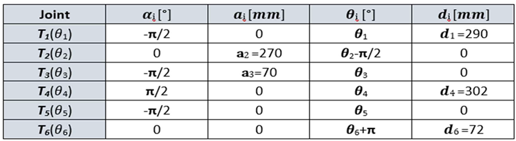
According to dimensions provided by ABB in the product specifications for ABB 120 IRM (Figure 3), D-H kinematic parameters are shown in TABLE 1, while D-H link coordinate system and frame assignment for the robot joints, is presented further in Figure 6. To represent the relation between two frames Σi and Σi-1 such as the representation or specification of the orthogonal coordinate frames, by translating or rotating frame Σi-1 to achieve the next frame Σi, joint to joint homogenous transformation matrix Ti is used, where . For every joint i, greater than 1, associated with the degree of freedom, each transformation matrix is a function of θi angle, which gives the relationship between the frame Σi over the frame Σi-1, starting with the initial frame Σ0. Therefore, using the D-H parameters, for every link or joint coordinate i, representing each of the 6 links, such that where m is 6, Ti can be written, by successive post multiplication of the single transformations [27]:
The D-H parameters from TABLE 1, defined by the manipulator kinematic parameters, are substituted into the homogeneous transformation matrices, or sometimes called relative transforms, for generating the joint-to-joint transformation matrices for each frame and link dimension [24], which maps the coordinates of adjacent links i − 1 over the link i. The initial frame Σ0 is moved to achieve the next frame Σ1, origin O1 and rotate it with about the x-axis. Translation distance along the z-axis is L1, as pointed in Figure 7a.

Table 1.
ABB 120 IRM D-H parameterization used to determine the homogeneous transformation matrix.
Frame Σ2 is achieved by shifting Σ1 with along the z-axis and rotate it with about the z-axis. (Figure 7b)
Frame Σ3 is achieved by shifting Σ2 with along the z-axis and rotate it with about the x-axis. (Figure 7c)
Frame Σ4 is achieved by shifting Σ3 with along the x-axis, shifting with along the z-axis and rotate it with about the x-axis. (Figure 8a)
Frame Σ5 is achieved by shifting Σ4 with along the x-axis and rotate it with about the x-axis. (Figure 8b)
Frame Σ6 is achieved by shifting Σ5 with along the x-axis and rotate it with about the z-axis. (Figure 8c)
Matrix denotes the homogeneous transformation, by relating the description of a point in frame Σi to the description of the same point in frame Σi-1. The algebraic approach of the forward kinematics can be expressed as a matrix successive concatenation, by multiplying all six transformation matrices according to D-H convention [27], [28] and [29]. This allows the complete transformation from the origin of the base robot to the RM end effector by splitting of the transformation matrix into matrices, which generates a rotation matrix and a translation vector to calculate the position and orientation of a kinematic chain from the joint variables.
By extracting the fourth column of T, the end effector position vector is achieved. Further, is the normal vector, the sliding vector and is the approach vector:
By defining D-H parameter table and calculating the homogeneous transformation matrix T, a mathematical representation of the robot forward kinematic structure is achieved. To calculate the inverse kinematics solutions, the homogeneous transformation matrix T is the starting point, referred as the input for the inverse kinematics problem. In this scenario, for reaching a desired position and orientation of the end-effector, each joint coordinates are calculated, associated with the degree of freedom denoted by the set of unknown variables (θ1, θ2, θ3, θ4, θ5, θ6).
3.1.2. Inverse Kinematics
There are several ways to calculate the inverse kinematics solution, which can be tested with respect to each other, geometric approach - used further in this paper, as well as the algebraic method which can be solved by equation systems using numerical methods [21]. In order to simplify the problem, kinematic decoupling method is implemented by splitting the inverse kinematics general problem into two separate directions using the relative position and orientation of the intersection of the three reference systems in one point: first homogenous matrix -defines the position and second matrix -for solving the orientation problem of the spherical wrist. The geometric solution for the first joint angle is determined by reducing the three-dimensional problem into a XY-plane, taking into consideration only the first three joints and keeping in mind that the wrist motion of the fourth coordinate system is not influencing the equation. The first angle θ1 is calculated by computing the position of the wrist P4 from the rotation matrix T by using the approach vector a, and position vector p, of the end effector position. (Figure 9) Geometric solution for the inverse kinematics of the first link angle θ1 admits two possible solutions although is not always physical or mechanical possible, θ1 and (θ1 + π), as calculated below:
Geometric solution for the inverse kinematics of the joint angle θ2 and θ3, as drafted in Figure 10, admits two solutions.
For elbow up:
For elbow down:
As discussed, by applying the kinematic decoupling approach and using the desired orientation of the end effector, the last three joint angles can be calculated by finding a set of Euler-angles corresponding to the desired rotation matrix which is equal to the rotation matrix for the Euler-angles [28] and [29].
For the nonsingular case, meaning , which implies, there are two possible geometric solutions for the inverse kinematics orientation:
For wrist up:
For wrist down:
For the singular configuration (θ5 =0), meaning cos(θ5) in the matrix is 1, it generates an infinite number of solutions (degenerate solution, in this case, θ4 cannot be determined), only the sum of θ4+ θ6 can be found, thus it is common to arbitrarily set θ4 to null and solve the θ6 joint angle.
For wrist up:
For wrist down:
Figure 11 shows the inverse kinematics motion space simulation for RM joint angles and .
3.2. Assembly Tasks Planning and STPN Model
3.2.1. Planning Assembly Tasks
A/DRC assisted by ABB 120 IRM performs assembly and disassembly operations of a predefined 5-component product for two workpieces called WP1 and WP2, [7], [12] and [30]. The assembly flow process starts from storing and supplying subcomponents to finally delivering the fully assembled selected type of product onto the cell conveyor unit, which functions as a transport line. The workpiece to be assembled consists of five components: a base pallet, a body, a top, and two inserted cylinders, which may be either plastic or metal. For introducing flexibility in manufacturing, two workpieces can be handled in the robotic cell depending on operator’s selection. Top part is different, it can be either with square edges (WP1) or with rounded shape (WP2). The assembly process involves RM performing repetitive tasks of picking, handling, and transporting the subcomponents to the specified assembly area within the cell, task planning for the assembly process of WP1 or WP2, is shown in Figure 12. First, the base pallet is placed on the conveyor FC2, then product is partially assembled on a suspended bracket called Assembly Tray FC1. Body, top and cylinders are fitted in this location, then the structure is placed on the base pallet. Once the assembly is complete, the assembled workpiece is transported via the conveyor FC2 to the right side of the cell, the delivering point for assembled products, serving as a starting point for another manufacturing process.
3.2.2. STPN Model for Assembly
STPN model for A/DRC assembly operation starts by selecting one of the workpieces WP1 or WP2 to be integrated per component by the manufacturing process into the final product. The assembly process involves RM is picking the subcomponents from the storage units, handling and assembling them on the Assembly Tray FC1 and transporting the assembled workpiece on the conveyor FC2 to the right-side exit line of the cell, all this with the corresponding time durations. Synchronizing signals for assembly process are required, for time-align and monitoring checks issues of the PLC program. Therefore, Ready signal from previous operations like assembly or disassembly is a condition for starting the current cell task. The STPN model, simulated in Sirphyco [31] is shown in Figure 13.
The STPN is defined as follows:
where is the Timed Petri Net model corresponds to the assembly function.
, is the partitioned set of assembly model places:
(Orange color places), represents the states of the PLC program functions control tasks:
(Olive color places), are the discrete states of the flexible assembly tasks:
(Blue color places), are the states generated for cell monitoring and supervision of the important tasks during flexible assembly process:
is the partitioned transition set of assembly for :
- , are the discrete transitions acknowledging that no other operation is running (Assembly or Disassembly);
- transition for assembly conditions: SCADA assembly command is ON, and cell is Ready (no other operation is running);
- , are the discrete transitions of the flexible assembly tasks;
- is the final transition when assembled workpiece is transported by the conveyor FC2 to the right-side exit line of the robotic cell.
For assembly on the robotic cell assisted by ABB 120 IRM, the supervision places (Figure 14), in the set (56) delegated to monitor the transitions set (57) are as follows:
- P30, T1 supervision transition is executed when assembly task starts, conditions are met, meaning SCADA assembly command is ON, and cell is Ready (no other operation is running).
- P31, transition T5 is executed when Base plate is placed on the conveyor FC2.
- P32, T7 supervision transition is performed when Body part is placed on the Assembly Tray FC1.
- P33, T9 transition is carried out when assembly actions for choosing Top Part with Round or Square Edges corresponding to selected WP1 or WP2 to be manufactured.
- P34, transition T11 is executed when choosing the Metal cylinder for assembly.
- P35, transition T13 is executed when choosing the Plastic cylinder for assembly.
- P36, T15 transition is running when the assembled workpiece on the conveyor FC2 is transported to the exit line of the robotic cell.
- P37, T16 supervision transition is executed when Assembly task is finalized in the cell and Ready signal is set to ON.
is the input incidence function.
is the output incidence function.
is the initial marking set of tokens corresponding to Assembly places of the STPN modeled process.
is a function that defines the timings associated to the transitions.
is the set of external events.
Sync application in definition (51) is a function from the set of discrete transitions corresponding to the assembly of A/DRC external events joined with the neutral element e,
The synchronization signal that generates Ready signal when no Assembly task is running in robotic cell:
The synchronization signal that generates Ready signal when no Disassembly task is running in robotic cell:
3.3. Disassembly Tasks Planning and STPN Mode
3.3.1. Planning Disassembly Tasks
Workpieces ready for disassembly process are delivered on conveyor FC2, on the right side of the robotic cell, serving as a “check in” location point for products ready to disassembly. Further, workpiece is transported by conveyor FC2 to the dismantling location where RM will do the rest of the disassembly process through repetitive tasks of picking and placing subcomponents in the reverse order as assembly operation was performed. Cylinders, top and body parts will be extracted and placed to the dedicated slide compartments on the cell, front bottom panel. Last task performed by RM is taking the base pallet from FC2 and placing it into the designated storage place W1, inside the cell. Task planning for the disassembly process is shown in Figure 15. The local control system-HMI is shown as well, for selection and starting the disassembly process.
3.3.2. STPN Model for Disassembly
The disassembly process involves first that WP1 or WP2 workpieces will be delivered for disassembly process on the right side of the station and transported on the FC2 conveyor. RM is picking and placing the structure to the Assembly Tray FC1 where all the subcomponents will be dismantled, then finally the last part is handled, base pallet, which will be stored on the dedicated storage unit. All this disassembly operations and transitions are executed with the corresponding time durations. The same two synchronizing signals, as for assembly process are required, for time-align and monitoring checks issues of the PLC program. Therefore, Ready signals from previous operations like assembly or disassembly will be the starting condition for disassembly task. The STPN model, simulated in Sirphyco [31] is drafted in Figure 16.
The STPN model for the disassembly process is defined by the following set:
where: TPN is the Timed Petri Net model, is the external events array of transitions, and Sync is an application signals set corresponding to a set of transitions- conditions to be met, defined as external events involved in the disassembly process.
The TPN is a sextuplet:
The elements of the Timed Petri Net model corresponding to the disassembly function are:
is the partitioned set of disassembly , model places:
(Orange color places), represents the states of the PLC program disassembly functions control tasks:
(Olive color places), represents the discrete set of states, associated with the functions of the flexible disassembly tasks:
(Blue color places), are the states generated for robotic cell monitoring and supervision of the main tasks during flexible disassembly process for WP1 or WP2:
- is the partitioned transition set of assembly for :
- , are the discrete transitions acknowledging that no other operation is running (Assembly or Disassembly).
- transition for disassembly conditions: SCADA disassembly command is ON, and cell is Ready (no other operation is running).
- , are the discrete transitions of the flexible assembly tasks.
- is the final transition when workpiece subcomponents are dismantled, transported, placed and stored in their storage units.
For robotic cell, WP1 or WP2 disassembly operation, assisted by ABB 120 IRM, the supervision places in the set (74) delegated to monitor the transitions in the set (75). Supervision transitions modelled with STPN in Sirphyco, Figure 17, for the disassembly process of the WP1 or WP2, are as follows:
- P22, T1 supervision transition is executed when SCADA disassembly command is triggered.
- P23, T4 supervision transition is executed when disassembly task starts, conditions are met, meaning SCADA disassembly command is ON, and cell is Ready (no other operation is running).
- P24, T5 supervision transition is executed when workpiece to be dismantled is delivered on transport conveyor FC2, at a specific position to be handled by the ABB 120 IRM.
- P25, T6 supervision transition is executed when upper part of the workpiece is placed on the Assembly Tray FC1, and RM is extracting the first cylinder.
- P26, T7 transition is carried out when and RM is extracting the second cylinder.
- P27, T8 supervision transition is performed when Top part is picked and placed by RM on the corresponding storage unit.
- P28, T9 supervision transition is executed when Body part is picked and placed by RM on the corresponding storage unit.
- P29, T10 supervision transition is executed when Base part (Pallet) is transported by the conveyor FC2 to the right-side exit line of the cell, to be external stored and Disassembly process is finalized and Ready signal is set to ON.
- is the input incidence function.
- is the output incidence function.
is the initial marking set of tokens corresponding to Disassembly places of the STPN modeled process.
is a function that defines the timings associated to the transitions.
Same as in Assembly process, the Sync application in definition (69) is a function from the set of discrete transitions corresponding to assembly and disassembly external events:
The synchronization signal that generates a Ready signal when no assembly task is running in robotic cell:
The synchronization signal that generates a A/DRC Ready signal when no disassembly task is running in robotic cell:
3.4.3. D Virtual Model Implementation Using Siemens NX MCD
In this paper, 3D modelling and dynamics of the physical process including robot kinematic motion is developed in Siemens NX MCD [13], starting with the ABB 120 IRM model, developed in CATIA CAD Tool. (Figure 18) The rest of the integrated mechatronic equipment is also digitally modeled like the conveyor belt, gripper, storage units for each of the final product components and the housing of the complete setup. In this 3D model project, we use specifications and models from manufacturer catalogs to accurately replicate and mirror the physical layer. This approach ensures a consistent representation of the machines in the factory, aligning their dimensions, physical properties, and kinematic behavior with the actual mechatronics equipment [32] and [33]. 3D model representation, as an important part of the Digital Twin (DT) technology has to be converted to a proper simulation model that interacts with the twins, using specialized software tools, by integrating mechanical and software components into a unified simulation environment [1] and [2].
These include product lifecycle management (PLM) platforms, such as Siemens NX MCD-used in this research, which integrates Siemens Digital Industries Software products, or other 3D factory simulation software solutions for manufacturing and robot offline programming (OLP). MCD is an application inside Siemens NX that allows the simulation and design of kinematic models using external signals based on CAD files. The physics-based 3D model, utilizing Digital Twin (DT) technology, can be controlled and simulated in real-time with the actual PLC through Hardware-in-the-Loop (HIL). This approach enables early verification of the code and identification of potential issues for engineering process control program validation. As shown in Figure 18, 3D model in NX MCD design starts with creating Solids, then to each part it gets assigned a Rigid Body feature. For that, physical characteristics are assigned as well like weight, center of mass and inertia which influence the body dynamics in the simulation. Further Collision Body proprieties are assigned to motion graphical elements, to be able to have physical interaction with the other objects. Machine motions and dynamic interactions between components are applied for each of the 6 robot axes (θ1, θ2, θ3, θ4, θ5, θ6) therefore NX MCD joints connections implementation is performed, to enable virtual kinematic movements [32], according to linked signals interfaced and calculated by the virtual controller. Furthermore, controls are defined for the physics simulation of the entire machine in the digital space, providing an interface for simulating kinematic model behaviors in response to PLC inputs. NX MCD allows communication protocols with external programs, in this project standard OPC UA interface is used for broader connectivity. The 3D virtual interface, NX MCD establish a communication over OPC UA with PLC. A separate MCD signal should be created for each IO Field variable which enables the mapping of sensor and actuator signals to virtual components for precise testing.
4. Digital Twin Technology
4.1. Multilevel Architecture
This paper focuses on the design, implementation and testing of a DT application for A/DRC line assisted by ABB 120 IRM. Although on large-scale, complex systems, distributed architecture is preferred, in this application, a centralized multilevel architecture is applied for virtual robotics validation, to enable product simulation and for the control strategy of the presented manufacturing processes. A fully functional DT application is implemented in this research, by developing a virtual replica for A/DRC operations of two different, predefined workpieces, each of the products consisting of 5 subcomponents [7]. In case of disassembly, recovery functionality of the disassembled components for future reprocessing or repair is also implemented. The multilevel control structure, features both distributed and centralized topology, all shown in Figure 19, consisting of the following equipment layers:
- Remote operation level, SCADA and local HMI, for remote control of the A/D devices, for handling operations and for real time monitor and data acquisition [14].
- Communication level, handles data transfer and A/D tasks synchronization. SIMATIC IOT2050 has an important role in this hardware structure concept, as a bidirectional data transfer gateway for all edge devices with the Cloud platform [9].
- Control level with PLC S7-1200 which acts as a Central System that controls and synchronizes the overall A/D operations. Moreover, the PLC handles communication and program execution for all devices like ABB IRC5C IRB120 controller, with the Intelligent Siemens Servomotor Drives SINAMICS V90 and NVIDIA Jetson Nano - a small, powerful computer used for embedded applications, especially for Image-system processing solutions. Components detection task is performed by the OVP 800 video processing unit (VPU) with OpenCV-Python open-source library [16].
- Process level, the robotic cell devices like: ABB 120 IRM with electric gripper, conveyor motors, storage, electrical and pneumatic actuators, all IO Field sensors and HMI KTP 700 as A/DRC local visualization and control system.
4.2. PLC Software Design
In the context of HIL PLC simulation, DT technology can be adopted to test and enhance the performance of the physical PLC, leading to improved productivity and reduced errors in the manufacturing process. Within the framework of Industry 4.0, where the fusion of physical and digital systems drives innovation, PLC DT technology is gaining greater importance. As technology continues to evolve, even more sophisticated applications of PLC DT technology are expected in the future. Starting from the main idea of building a virtual replica of the physical process and behavior, a PLC project is design in Siemens TIA Portal to simulate, monitor, and optimize its performance before software deploying and onsite commissioning [34]. Moreover, additional features can be added, like integration with IoT devices or Cloud Storage data and History Cloud DT playback for tracking and diagnosing potential events or problems that can arise during the normal operation [9]. Therefore, for developing an accurate virtual model, PLC software is mirrored, keeping the same logics and behavior as the physical system, but programmed to communicate via OPC UA with the twins - NX MCD 3D virtual model [13]. OPC UA is one of the most straightforward and efficient protocols for enabling communication between multiple Industry 4.0 and IoT applications, minimizing the potential for communication issues, in this project, PLC acts as an OPC Server. Additional software tools are integrated for model validation, simulating various scenarios and control strategies, detecting potential issues or software bugs. The physical system I/O handler providing robotic cell status from sensors, actuators and ABB RM positions and axis angles is replicated within a separate PLC function block -called Virtual I/O handler, by evaluating the same control logic and sensor behaviors. When DT is active, Virtual I/O handler is the middleware for I/O data sent and received by the virtual model, as seen in Figure 20.
ABB RobotStudio functions [19], dealing with operations of the robotic cell like product assembly and disassembly are also emulated in the main PLC, generating the designated motion angles and positions through inverse kinematics implementation and sent further to Virtual I/O Handler. The core function that implements the analytical method algorithm for computing the joint values (θ1, θ2, θ3, θ4, θ5, θ6) of the ABB 120 IRM is the inverse kinematics function block. (Figure 21) Function blocks for inverse kinematics calculation, motion planning, and path generation, along with the software integration, communication with Virtual I/O Handler, and operation within the DT model, are developed in Siemens TIA Portal V17 [34]. The design aims to create a reusable framework applicable to other PLCs. While modern PLCs feature more efficient processors and expanded memory, implementing and designing a 6-DoF robot inverse kinematics calculation remains an uncommon task in PLC programming and engineering. This is because analytical methods for determining joint solutions based on the robot end effector's position require intensive mathematical computations, particularly higher-order matrix operations. These demands challenges related to PLC-specific issues, such as execution cycle time limitations and expertise level for code optimization. The designed program calculates and returns a single joint angle solution based on the robot arm's position, provided as input from the ABB RM RobotStudio emulation software module, keeping the standard ABB robtarget data type format for position. Based on the SCADA user input selection, whether it involves: visualizing the robot's live parameters or real-time process data, opting to model and simulate various A/D operations with different cycle times, analyzing and compare performance or identify potential issues, the PLC consistently receives the end effector's position as an input. Based on the provided linear speed parameters, a separate function block handles path planning and motion control by segmenting the path between robot targets and interpolating the positions. The function block responsible for path planning and controlling linear motion (using the MoveL command) from the initial position to the desired final position is shown in Figure 22. It employs a smooth function, known as Cubic Polynomials, when the desired velocities at intermediate points are non-zero and is an efficient way to interpolate between two points in space, ensuring that both - position and velocity constraints are met.
Cubic polynomials is a commonly used method in robotics for smooth path planning, particularly in applications requiring continuous motion and velocity profiles. (Figure 23) This method ensures efficient and precise control of robotic systems, balancing simplicity with effective performance in many practical scenarios. A separate robot position is generated for each timestamp i out of n time segments, which is then used as input for each calculation step of the robot joints through the inverse kinematics algorithm. A watchdog was implemented to ensure smooth graphical movement at each timestamp during the robot's motion between two targets.
This guarantees stable, real-time communication, rapid data reception, preventing error handling and unintended manipulator movements, [6] and [29]. Out of the 8 generated solutions for the inverse kinematics, a single solution is selected by computing the best fit that complies to the mechanical limitations and physical characteristics of the ABB 120 IRM (as shown in Figure 3). This solution is chosen based on the target configuration quadrant for axes 1, 4, and 6, along with the robot's target data type. Robot task space trajectory-Linear Motion simulation in MATLAB [22], is presented in Figure 24.
Three conditional execution controls are implemented in the main PLC program OB1, as an option that determines if the specific instructions or module will be executed, according to operator choice, as seen in Figure 20: History Cloud Simulation, Cloud Storage Source and Virtual Commissioning. In normal situation, with no user intervention in the cell functionality, the A/D operations are carried out/executed on the physical system. The DT is turned off, and essential robotic cell structured data, such as axis angles, positions, sensor statuses, actuator states, and various process stages—are captured and stored in a JSON-like format in the Cloud. Cloud is used to collect, process, and store data for real-time analysis and long-term storage [9].
In this project setup, MongoDB Cloud platform is selected for its flexibility, scalability, and ease of use, making it an ideal solution for virtually mapping the entire physical process. The calculated virtual data can be stored in the Cloud, instead of real process data, when the DT system is running, this option is selected from the SCADA DT Panel. By reading the Siemens PLC DB23 process live data, Node-RED is used to store data in MongoDB offering a powerful, flexible, and scalable solution for handling data from both sources [15].
Virtual Commissioning option is also integrated into the system by testing a Clone PLC functionality against the real function block programs. Sensors from the physical system are integrated into the digital model allowing real-time data to be used for the simulation. The real physical I/O handler sensor data can be fed into the virtual system, enabling the simulation to reflect real-world sensor behavior. Therefore, the readings from conveyor and ABB IRM can be compared to the calculated values data in the DT to ensure consistency and accuracy. History Cloud Simulation is used the replay and simulate past scenarios and robotic cell system operations based on real-world data collected over time, often using data stored in the Cloud. The process data, along with the robot's state, axis angles and positions are logged and can be monitored at each moment during the motion path segmentation. This simulation can be used for various purposes, such as performance analysis, predictive modeling, system optimization, and event failures to better understand process behavior and make more informed decisions for the future.
4.3. DT Communication, Synchronization and Control
For building the 3D virtual interface, to be able to connect the PLC in a HIL configuration, NX MCD establish a communication over OPC UA [13], therefore a Signal Mapping table is required for cross-reference connection with external signals, configured in the OPC UA Server from PLC. The OPC interface supports mapping with the IEC61131-3 language-PLC specific protocol, offers wide range of use and connectivity. Moreover, OPC UA is more and more preferred as standardized protocol to transfer data between different levels of automation. The communication is done in real time, and information can be transferred between client and server and from server to server, the minimum update time for OPC is approx. 100ms. When using a virtual controller in a Hardware-in-the-Loop configuration seen in Figure 25, a physical PLC is needed to synchronize and run simulation with the same internal clock speed as the rest of the system, avoiding communications latency between the PLC and emulation software [35]. Further, PLC software design is also providing a new approach, besides the logics for the robotic cell and RM automation control - known as the physical layer, it provides communication interface links through PROFINET IO to SCADA and HMI [14]. For linking PLC with the DT, an extra gateway is used, SIMATIC IOT2050, providing IoT support for data to be transmitted to the Cloud and can exchange data between physical and virtual models, providing data transmission and data aggregation, in case is needed. Is well used for converting a range of communication protocols, due to specific feature like its capability of Remote accessing I/O’s (Digital, Analog) and expansion with different types of smart sensors or Edge Devices, [9] and [36].
4.4. Virtual Commissioning Concept. Hardware-in-the-loop (HIL) Simulation
Aligning with the current trends in manufacturing, the integration of twins in engineering process is accelerating mainly due to Industry 4.0, bringing these “smart” manufacturing systems capabilities into digital world. As part of the DT technology, VC tool concept and technique is used, offering the potential to minimize the considerable delays and expenses typically involved in the challenging process of classical commissioning, system integration and operation with (PLC).
By using virtual models or virtual workspaces to simulate the behavior of physical systems, especially desired robot behaviors, allows early identification of potential issues generated from the process of physical integration and commissioning without shutting down production. It provides a safe and secure powerful tool for remote real-time monitoring, optimizing performance, simulating patterns and predicting maintenance needs or emerging outcomes, leading to smarter decisions and enhanced overall efficiency [5]. Therefore, VC increases the production and performance on a long-term basis by optimizing the operations tasks, improving the traceability by monitoring, analyzing and tracking every aspect of all manufacturing process and to significantly reduce the human risks, delays and costs associated with the real on-site commissioning. However, for VC to be accurate and successful model-driven DT, the process representation, virtual plant model and tasks simulation must precisely represent the real manufacturing system.
Since early development of VC for manufacturing system, there are 4 commissioning strategies/configurations used mainly to check, debug and perform tests the controller behavior, system implementation and manufacturing operations are working as expected.
- Real or classical commissioning: testing the physical plant (Manufacturing devices) against the physical hardware controllers (PLC) without the help of digital modeling techniques. In this case real physical plant is tested on the site, the real physical controller is connected to the real physical plant.
- Hardware-in-the-Loop (HIL), meaning virtual model that is used to test and control the real physical controller.
- Reality-in-the-Loop, alternatively, involves testing virtual controllers against a constructed or real, physical plant.
- Software-in-the-Loop (SIL) or Constructive Commissioning, employs testing both, virtual plant model and Virtual controller.
The presented manufacturing technology allows the integration of the VC concept by taking advantage of the integrated bi-directional data exchange flow between the dynamic digital representation and the physical system. To connect the A/DRC hardware controllers with the NX MCD 3D model virtual plant, mainly HIL simulation strategy is adopted, implemented and performed as Soft Commissioning approach, by testing the designed PLC programs against the physical PLC. (Figure 25) By using the real physical controller, HIL configuration offers the advantage of delivering the same performance as it would run in actual production by testing the hardware into all the situations to make sure it can succeed in all scenarios as programmed. Same happens when there is a big software or hardware change, it ensures that everything still works the way is intended. As mentioned, a key requirement for testing VC strategy setup is that the virtual factory model must behave exactly as the real model.
In what concern HIL implementation for virtual plant models to work in tandem with PLC, since simulation has a specific, separate internal clock, this has to be synchronized with the real, onsite PLC, for tasks to operate and for time dependent functions to remain valid. For the implemented DT, specific functions are designed in order that PLC to be manipulated, to synchronize and run in the same speed as the rest of the system and not affecting the performance of the test. HIL focuses on the PLC software that operates these systems.
Its primary benefit is the ability to identify errors early on the factory implementation process, thereby reducing the need for extensive debugging during the physical commissioning phase. A set of PLC function blocks are implemented for the kinematic computation, from modeling in MATLAB [22], to PLC code, for digital simulation environment of the complete engineering process.
As described in chapter 2.2.4, Virtual 3D Model is developed in the Simatic NX MCD, software with a big focus in manufacturing and mechatronics lines design, by integrating robots technologies from many different brands like ABB, KUKA and Fanuc and allowing big connectivity feature [13].
5. Remote Monitoring and Control
5.1. Digital Twin Control Panel – SCADA
SCADA plays a critical role in DT technology implementation, visualizing real-time data from sensors, actuators, and other devices connected to physical assets. Data is crucial for the DT, by using real live data as well as the data aggregated/calculated or Cloud history, to accurately replicate and monitor the physical system in real time by acting as the bridge between physical systems and their virtual counterparts. SCADA systems serve as the backbone for DT technology by supplying the real-time data needed in accurate simulations and monitoring purposes [1], [14]. Together, they create a powerful tool for improving system performance, predicting maintenance needs, and enabling smarter decision-making across industries. This integration is becoming increasingly important as businesses adopt Industry 4.0 and IoT technologies to stay competitive in a data-driven world. SCADA systems enhance the capabilities of twins by collecting, monitoring, and visualizing data from physical process, enabling better decision-making, predictive analysis, and system optimization [21]. Operators can test various scenarios, visualize them in SCADA, optimize workflows, and model the effects of process changes before implementing them into the physical system. Operators can monitor performance, make adjustments from anywhere, especially in remote facilities which can be supervised and tested using a combination of SCADA and DT virtual models, ensuring flexibility in managing complex systems.
In this research, for VC implementation of A/DRC physical process, beyond the 3D digital model representation, there is a need for a graphical user interface (GUI) tool. This visualization tool, serving as an DT operator control panel, is essential for interacting with the DT, it refers to a seamless two-way, bidirectional automated data exchange interface between physical and digital objects. It facilitates data monitoring, analysis, and comparison, as well as signaling and processing various events. Additionally, it supports simulation time reporting, user interaction, and setup control. SCADA also allows the users to manage data and control different scenarios or operations within the DT platform, including custom mimics- interactive graphical displays, especially design for testing the calculation of the inverse kinematics, DT interaction and process representation based on live and history Cloud data. These mimics allow the user to perform and test in DT virtual model various functions for centralized control and management of different hypotheses and scenarios. This enables testing and diagnosing potential operational lags or calculation errors and identifying performance issues or slowdowns in the engineering process. As seen in Figure 20, by using the computation resources for PLC code execution (as described in Section 4.2) user can take advantage of the visualized interactive data regarding the inverse kinematics calculation by entering the end effector robot position given as an input, all the 8 possible solutions are displayed on the screen. Rotation matrix is also visualized, and the correct solution is highlighted in red. (Figure 26) Based on the operator's selection, clicking the Simulate button allows the robot's movement calculated set of angles to be visualized on the 3D model within NX MCD. The user can monitor and analyze real-time DT readings, at each step of the robot's movement, starting from the given position to final target, including linear translation path segmentation and inverse kinematics calculations. (Figure 27) Robotic cell performance parameters can be monitored on this mimic, by setting different linear motion velocities or robot axis speed, allowing various operations to be tested, including using Live Robot data as part of the Digital Shadow concept within DT technology. If a test scenario meets the required performance criteria, the validated speed parameters can be downloaded by the operator into the PLC. Historical Cloud Data is also presented, upon request is made available a target event time is entered and sent further for processing in Node-RED for building the necessary Cloud interrogation queries, [37] and [38]. (Figure 28) Further the retrieved data is plotted on the screen, shown in Figure 29, the major timeline spikes are visualized from the 180 seconds History interrogation query time and can be sent for playback in the DT 3D Model representation in NX MCD visualization.
5.2. IoT-Cloud Based Control and Data acquisition
The purpose of the presented architecture features the IoT Cloud connection for collecting all IO Field sensor data, enables database storage and analytics for integrating the processed data into DT application, for virtual historical and real-time process presentation [38]. Using IoT-Cloud based DT online monitoring system brings important features for the end user, regarding process information and online remote control of the A/DRC tasks using cutting edge technology to monitor and to detect abnormal behavior and equipment failure using model-driven HIL simulations. Moreover, Cloud storage providers offer robust security features, including encryption, access controls and compliance with industry standards, especially ISO 27001, regarding information security management system [1], [9] and [36].
The proposed framework (Figure 30) for controlling and remotely monitoring of the A/DRC via the model-driven DT using IoT consists of the following components:
- IoT sensing device.
- Embedded computer NVIDIA Jetson Nano, acting as a Node-RED IoT interface and Docker Engine client-server application. Remote connection is also available through dedicated VNC-Compatible Free Remote Desktop Software [37].
- ABB IRC5C controller, execute the user configured program for the industrial robotic manipulator of the robotic cell and communication to PLC.
- Siemens IOT2050, an IoT gateway device, enables the bidirectional communication of the PLC with the IoT Cloud platform over a wireless connection.
- Siemens PLC 1214C type, acting as main control unit, send and receive data from all the robotic cell devices including LAN connected servo drives, process sensor data and is responsible with synchronization of the A/DRC tasks. Data is further available for SCADA system, Cloud storage (MongoDB) and DT application.
Locally, at the operation level, by using the station HMI or on the Remote SCADA application, user can control and simulate the process A/D operations, as well as monitoring all the signals, sensor values, calculated data and RM motion positions and angles transmitted by PLC on the screens [14]. Additionally, by using the onsite ABB touch pendant, operator can execute the actions configured by user in the ABB IRC5C controller and programmed in RobotStudio [19].
The video processing unit, OVP 800, by running ROS2 Humbles camera management, controls the three IFM Cameras video streams through the IFM3D_ROS2 library. It facilitates data exchange with the PLC and integration with Node-RED hosted on Embedded computer NVIDIA Jetson Nano which acts as a IoT gateway and Cloud middleware device [15], [37]. (Figure 31) By integrating the video processing unit connection with the Jetson Nano, OVP 800 acts as a IoT sensing device. Jetson Nano embedded computer can send all the image processed data, robotic cell events and sensor data to the IoT Cloud platform over a wireless Internet network connection for storage and for further vision data processing [16], [17]. Siemens IOT2050 is a cutting-edge platform ideal for developing IoT smart applications and automating various industrial processes, designed for efficient IoT data management and communication [36]. In this DT project, it allows the integration with cell devices and sensors, send/receive data to/from PLC, enabling real-time data collection, processing, and control via Cloud platform with enhanced connectivity features. (Figure 30)
Data collected on the Cloud platform (MongoDB) can be further manipulated for advanced processing, prepare it for analysis and presentation, for building different IoT Cloud applications such as remote SCADA for monitoring and Data analysis Server, moreover for receiving an earlier robotic cell timeframe data set for playback in DT application [9]. Network connection reliability for Wi-Fi and Internet has a critical role, therefore in the event of a Wi-Fi connection failure, IoT capability and functionality for Cloud based Control and Data acquisition is affected, no data transmission is accomplished, only DT warning messages and Cloud reporting services will be pushed in the application message viewer.
5.3. Remote HMI VPN Control
The proposed system uses two SCADA applications, one locally and one remote for monitoring and control of the A/D operations on a robotic cell process, equipped with an ABB 120 IRM. The structure and functionality of the entire system is based on a multilevel, decentralized architecture, integrating IoT, smart manufacturing and intelligent digital technologies, like VC technique in the context of Industry 4.0. Therefore, authorized users can safely monitor, control the cell process from anywhere, providing context that will help operators comprehend and predict potential unwanted events by delivering effective situational awareness. Moreover, by implementing and programming the robotic cell 3D virtual model A/D operations and task planning, including the ABB 120 IRM motions, Remote SCADA acts as a DT operator panel for process simulation, data collection presentations and analysis, with remote operation capabilities via Cloud or VPN [9], [35], [39] and [40]. The DT platform allows the complete management and control of the A/DRC processes and devices, with the possibility of customizing the simulations according to specific needs. In this project, a IoT Cloud based control and remote access application is implemented. Cloud Remote access allows operators to intervene on the robotic cell in a fast and secure way, reducing onsite interventions, saving time and resources. A third-party Cloud software platform is required, Mongo DB, to interconnect IoT devices, Cloud computing and storage in order to dynamically access remotely, for visualization and monitoring in SCADA, for analysis or prediction. MongoDB offer extra features as well, like integrating with other Cloud application or Reporting Service for data visualization [38]. Node-RED is a programming tool for dealing with IoT devices typically used for connecting different nodes, APIs and online services together to build powerful smart IoT integrated automation system. Node-RED server running locally on Jetson Nano IoT device provides Secure Remote access and visualize the robotic cell stored data on the Cloud. Simple and intuitive operational interface is developed for remotely monitoring the A/D operations and control all IoT devices, for security configuration, reports, trends, and alarm acknowledgment. Accessing Node-RED dashboard over the Internet through VPN connections provides enhanced security environment by using Industry-Standard Encryption like Secure Socket Layer (SSL), and Transport Layer Security (TLS) [36].
6. Robotic Cell Real-Time Results and DT Virtual Model Validation
To evaluate and validate the DT model environment against the FC real mechatronic process assisted by ABB 120 6-DoF IRM, several tests and analyses were performed. From the trajectory and joint angles compared results, the robot virtual model was able to follow reasonably well the desired trajectory profile. DT model slight differences were found, originating from PLC inverse kinematics algorithm calculations, especially from rounding the huge expressions of the rotation matrices and conversions, as well as some communication delays generated from data communication links, but these errors tend slowly to zero and does not affect the overall setup performance or bring behavior difference. (Figure 32)
Comparing the results, for a MoveL motion command from a selected robot target to home position, as seen in Figure 36, the proposed virtual model offers a very close equivalence to the engineering process and a decent approximation for robot tracking (Figure 33, Figure 34 and Figure 35), positioning and joint axes angles.
7. Discussion
This research paper was undertaken to build a HIL DT framework with Cloud solutions and Remote VPN capabilities for a robotic cell assisted by 6-DOF ABB 120 IRM based on a PLC implementation for RM inverse kinematic virtual model.
Modeling of the A/DRC operations is performed using Synchronized Timed Petri Nets (STPN) model based for task planning integration and control strategy validation.
In this work, as seen in results for model validation through motion simulation, the robotic cell DT with RM 3D model based on inverse kinematics motion, solution developed in PLC, can confidently replicate not only the position of the manipulated objects but also its orientation of the 6-axis robot manipulator behavior and interaction.
Although model calculation, simulation and PLC software designed is based on a robotic cell using the ABB 120 IRM, the robot model can be changed easily in the PLC function block inverse kinematics design calculation so that it corresponds to other similar robotic manipulators.
Following digital model developing and running simulations, real-time implementations are integrated within the digital environment for validation and testing, where the results from the physical system are cross-referenced with simulation outputs.
For A/DRC operations, synchronization with robotic cell signals and events is needed, for time-align and monitoring checks issues of the PLC program with the virtual controller. In a Hardware-in-the-Loop simulation, physical PLC is needed to synchronize and run simulations with the same internal clock speed as the rest of the system, avoiding communications latency between the PLC and emulation software, to ensures consistency in analysis.
While integration of DT technology into engineering processes is rapidly accelerating, primarily driven by the Industry 4.0 revolution, however, addressing the challenges of cost, security, scalability, and complexity in data management and Cloud communication and storage, are essential to its long-term success.
The implementation and integration of digital technologies in manufacturing, like VC, IoT and Cloud can enhance the overall productivity, performance, efficiency, and reliability of the robotic cell, although a DT system can have an expensive initial cost in designing and deploying into the real engineering process.
Low-latency communication between the physical robotic cell and its twin is crucial for real-time applications, which can be technically challenging. Robotic cell brings complexity in modeling and simulation, especially changes in physical system or adding extra operations and tasks in process require continuous updates to the DT model. Real-time data streams add complexity to monitoring and control like real-time data acquisition from IoT devices embedded in the robotic cell which collect data and store to the Cloud continuously.
Robotic cells generate vast amounts of real-time data therefore streams from IoT devices require advanced storage and processing capabilities. Real-time data collection and transmission rely on robust IoT ecosystems. Data processing enhance system capabilities, making real-time validation an indispensable part of modern operations although data quality checks and integration from various sources into a unified model is a complex task.
As DT technology continues to expand across various industries, it generates and processes vast amounts of sensitive data in real-time. Ensuring compliance with data regulations and robust security policies is not just a technical challenge regarding data complexity, vulnerable to cybersecurity threats attack, moreover it requires compliance with General Data Policies. Access control solutions in SCADA, PLC and Cloud environments, data classification - to identify and classify data based on sensitivity, data anonymization and end-to-end encryption during DT to Cloud transmission interface might be a solution.
8. Conclusions
Digital twin technology is a key element of the fourth industrial revolution. By integrating real-time data, cutting-edge simulations, and smart analytics, it offers deep, insights into the behavior and performance of complex systems, transforming industries and enabling smarter decision-making and operational efficiency.
This research work aims to evaluate whether integration of intelligent digital technologies in manufacturing systems and especially in the robotic domain, like VC, should be included in their suite of tool for testing the programs under different scenarios, for operations tasks, delays optimization and to minimize the costs associated with on-site commissioning.
The implementation and simulation of a DT model for VC against the real work environment provide greater engineering opportunity, allows for the design process to be more effective and brings a more efficient and convenient way for testing the behavior of physical systems. Moreover, DT along with HIL integrated VC, IoT and Cloud solutions are promising approaches for manufacturing industries to precisely calculate, control, monitor and predict every subsequent event of the physical process.
Adopting these smart technologies is increasing production performance through process optimization, ensuring high reliability of their system and reducing many risks towards cost production and safety. The DT virtual robotic cell enables the manufacturing company to explore new operational strategies for real-time control applications, such as adding components to the system to enhance production efficiency. Additionally, having a digital model upgraded with Cloud storage solutions can easily accommodate the growing data requirements allowing real-time data collection and monitoring of robotic cells equipped with IoT sensors, enabling faster decision-making, troubleshooting potential issues and significantly reduces downtime associated with maintenance tasks.
Future work should focus on addressing the challenges in Industry 5.0, such as the integration of collaborative robots into manufacturing systems, particularly within robotic cells, and their connection with DT technology. This is an area that requires further attention, designing robotic cells to ensure safe collaboration with human workers requires additional safety protocols, sensors, and programming. By adding layers of complexity in terms of data collection, processing, and response of the robotic cell, it requires advanced design, careful integration, and more sophisticated control systems to ensure efficiency and reliability. Moreover, the complexity of a robotic cell in its design, operation, and integration with DT should be addressed starting from adding multiple robots or adding extra tasks into a single robotic cell and combined with implementation of VC techniques in this setup.
Author Contributions
Conceptualization, all authors; methodology: A.F. (Adrian Filipescu), D.I., A.F. (Adriana Filipescu), and G.S.; software: G.S. and D.I.; validation: A.F. (Adrian Filipescu); formal analysis: G.S. D.I., and A.F. (Adriana Filipescu); writing—original draft preparation: A.F. (Adrian Filipescu), and A.F. (Adriana Filipescu); writing—review and editing: A.F. (Adrian Filipescu), A.F. (Adrian Filipescu); project administration: A.F. (Adrian Filipescu); funding acquisition, A.F. (Adrian Filipescu). All authors have read and agreed to the published version of the manuscript
Funding
This article (APC) will be supported by “Dunarea de Jos” University of Galati.
Institutional Review Board Statement
Not applicable.
Informed Consent Statement
Not applicable.
Data Availability Statement
Data availability is not applicable to this article as the study did not report any data.
Conflicts of Interest
The authors declare no conflicts of interest.
References
- Ma, Xin; Tao, Fei; Zhang, Meng; Wang, Tian; Zuo, Ying. (2019). Digital twin enhanced human-machine interaction in product lifecycle. Procedia CIRP. 83. 789-793. [CrossRef]
- Botín-Sanabria, D.M.; Mihaita, A.-S.; Peimbert-García, R.E.; Ramírez-Moreno, M.A.; Ramírez-Mendoza, R.A.; Lozoya-Santos, J.d.J. Digital Twin Technology Challenges and Applications: A Comprehensive Review. Remote Sens. 2022, 14, 1335. [CrossRef]
- Florescu, A. Digital Twin for Flexible Manufacturing Systems and Optimization Through Simulation: A Case Study. Machines 2024, 12, 785. [CrossRef]
- Kritzinger, Werner; Karner, Matthias; Traar, Georg; Henjes, Jan; Sihn, Wilfried. (2018). Digital Twin in manufacturing: A categorical literature review and classification. IFAC-PapersOnLine. 51. 1016-1022. [CrossRef]
- Negri, Elisa; Fumagalli, Luca; Macchi, Marco. (2017). A Review of the Roles of Digital Twin in CPS-based Production Systems. Procedia Manufacturing. 11. 939-948. [CrossRef]
- Guerra-Zubiaga, David; Bondar, Alex; Escobedo, Gilberto; Schumacher, Arthur. (2019). Digital Twin in a Manufacturing Integrated System: Siemens TIA and PLM Case Study. [CrossRef]
- Mincă, E.; Filipescu, A.; Cernega, D.; Șolea, R.; Filipescu, A.; Ionescu, D.; Simion, G. Digital Twin for a Multifunctional Technology of Flexible Assembly on a Mechatronics Line with Integrated Robotic Systems and Mobile Visual Sensor—Challenges towards Industry 5.0. Sensors 2022, 22, 8153. [CrossRef]
- Guerrero, L. V.; López, V. V.; Mejía, J. E. (2014). Virtual Commissioning with Process Simulation (Tecnomatix). Computer-Aided Design and Applications, 11(sup1), S11–S19. [CrossRef]
- Saha, O.; Dasgupta, P. A Comprehensive Survey of Recent Trends in Cloud Robotics Architectures and Applications. Robotics 2018, 7, 47. [CrossRef]
- Filipescu, A.; Simion, G.; Ionescu, D.; Filipescu, A. IoT-Cloud, VPN, and Digital Twin-Based Remote Monitoring and Control of a Multifunctional Robotic Cell in the Context of AI, Industry, and Education 4.0 and 5.0. Sensors 2024, 24, 7451. [CrossRef]
- Konstantinov, S.; Assad, F.; Ahmad, B.; Vera, D.A.; Harrison, R. Virtual Engineering and Commissioning to Support the Lifecycle of a Manufacturing Assembly System. Machines 2022, 10, 939. [CrossRef]
- Filipescu, A.; Ionescu, D.; Filipescu, A.; Mincă, E.; Simion, G. Multifunctional Technology of Flexible Manufacturing on a Mechatronics Line with IRM and CAS, Ready for Industry 4.0. Processes 2021, 9, 864. [CrossRef]
- Siemens NX Mechatronics Concept Designer (MCD). Available online: https://plm.sw.siemens.com/en-US/nx/cad-online/ (accessed on 20 January 2025).
- SIMATIC SCADA Systems. Available online: https://www.siemens.com/global/en/products/automation/industry-software/automation-software/scada.html (accessed on 20 January 2025).
- Node-RED web-based flow editor for remote control, Node-RED 4.0 released—News—Node-RED Forum (nodered.org). Available online: https://discourse.nodered.org/t/node-red-4-0-released/88815 (accessed on 20 January 2025).
- OpenCV. Available online: https://opencv.org (accessed on 20 January 2025).
- Microsoft Visual Studio. Available online: https://www.visualstudio.com/vs/cplusplus (accessed on 20 January 2025).
- Hadi Barhaghtalab, M.; Meigoli, V.; Golbahar Haghighi, M.R.; et al. (2018). Dynamic analysis, simulation, and control of a 6-DOF IRB-120 robot manipulator using sliding mode control and boundary layer method. Journal of Central South University. 25. 2219-2244. [CrossRef]
- ABB RobotStudio Desktop Robotics. Available online: https://new.abb.com/products/robotics/software-and-digital/robotstudio/robotstudio-desktop (accessed on 20 January 2025).
- Manocha, D.; Canny, J. F. Efficient inverse kinematics for general 6R manipulators. IEEE Transactions on Robotics and Automation, vol. 10, no. 5, pp. 648-657, Oct. 1994. [CrossRef]
- Lee C. S. G.; Ziegler, M. Geometric approach in solving inverse kinematics of PUMA robots. IEEE Transactions on Aerospace and Electronic Systems, vol. AES-20, no. 6, pp. 695-706, Nov. 1984. [CrossRef]
- MathWorks. Available online: https://www.mathworks.com (accessed on 20 January 2025).
- Chapelle, F.; Bidaud, P. Closed form solutions for inverse kinematics approximation of general 6R manipulators. Mechanism and machine theory, vol. 39, pp. 323-338, Mar. 2004. [CrossRef]
- Ionescu, D.; Filipescu, A.; Simion, G.; Șolea, R.; Filipescu, A.; Șerbencu, A. PLC Inverse Kinematics Model-Driven Digital Twin Focused on HIL for a Flexible Robotic Cell. 2024 18th International Conference on Control, Automation, Robotics and Vision (ICARCV), pp.1195-1200. [CrossRef]
- Hartenberg, R. S.; Denavit, J. A kinematic notation for lower pair mechanisms based on matrices. Journal of applied mechanics, vol. 77, pp. 215-221, June 1955. [CrossRef]
- Rocha, Carlos; Tonetto, Cristiane; Dias, Altamir. (2011). A comparison between the Denavit-Hartenberg and the screw-based methods used in kinematic modeling of robot manipulators. Robotics and Computer-integrated Manufacturing - ROBOT COMPUT-INTEGR MANUF. 27. 723-728. [CrossRef]
- Seven, O.F.; Ankarali, A. (2019). Inverse kinematics analysis of IRB120 robot arm. SETSCI Proc. ISAS ’19, vol. 4, pp.383-390.
- Nicolescu, A.F.; Ilie, F.M.; Alexandru T.G. Forward and inverse kinematics study of industrial robots taking into account constructive and functional parameters modeling. Proceedings in Manufacturing Systems, Volume 10, Issue 4, 2015, 157−16; ISSN 2067-9238.
- Almaged, M. (2017). Forward and Inverse Kinematic Analysis and Validation of the ABB IRB 140 Industrial Robot. International Journal of Electronics, Mechanical and Mechatronics Engineering, 7(2), 1383–1401.
- Ionescu, D.; Filipescu, A.; Simion, G.; Mincă, E.; Cernega, D.; Șolea, R.; Filipescu, A. Communication and Control of an Assembly, Disassembly and Repair Flexible Manufacturing Technology on a Mechatronics Line Assisted by an Autonomous Robotic System. Inventions 2022, 7, 43. [CrossRef]
- Sirphyco Simulateur de Réseaux de Petri, Sirphyco-Simulateur-de-Reseaux-de-Petri. Available online: https://www.toucharger.com (accessed on 20 January 2025).
- Bahani, Abderrahim; Ech-Chhibat, Moulay El; Ait el Attar, Hicham; Samri, Hassan. (2023). The Inverse Kinematics Evaluation of 6-DOF Robots in Cooperative Tasks Using Virtual Modeling Design and Artificial Intelligence Tools. The International Journal of Robotics Research. 12. 121-130. [CrossRef]
- Schluse, M.; Rossmann, J.. (2016). From simulation to experimentable digital twins: Simulation-based development and operation of complex technical systems. 1-6. [CrossRef]
- Totally Integrated Automation Portal, TIA Portal V17. Available online: https://www.siemens.com/tia-portal (accessed on 20 January 2025).
- Pacheco-Gutierrez, S.; Niu, H.; Caliskanelli, I.; Skilton, R. A Multiple Level-of-Detail 3D Data Transmission Approach for Low-Latency Remote Visualisation in Teleoperation Tasks. Robotics 2021, 10, 89. [CrossRef]
- Roy, S.; Vo, T.; Hernandez, S.; Lehrmann, A.; Ali, A.; Kalafatis, S. IoT Security and Computation Management on a Multi-Robot System for Rescue Operations Based on a Cloud Framework. Sensors 2022, 22, 5569. [CrossRef]
- Nițulescu, I.-V.; Korodi, A. Supervisory Control and Data Acquisition Approach in Node-RED: Application and Discussions. IoT 2020, 1, 76-91. [CrossRef]
- Omidi, S.A.; Baig, M.J.A.; Iqbal, M.T. Design and Implementation of Node-Red Based Open-Source SCADA Architecture for a Hybrid Power System. Energies 2023, 16, 2092. [CrossRef]
- Arenas-Rosales, F.; Martell-Chavez, F.; Sanchez-Chavez, I.Y.; Paredes-Orta, C.A. Virtual UR5 Robot for Online Learning of Inverse Kinematics and Independent Joint Control Validated with FSM Position Control. Robotics 2023, 12, 23. [CrossRef]
- VNC (Virtual Network Computing), RealVNC® Remote Access Software for Desktop and Mobile|RealVNC. Available online: https://www.realvnc.com (accessed on 20 January 2025).
Figure 1.
A/DRC with ABB 120 IRM. DT Physical and Virtual Layer Communication topology.
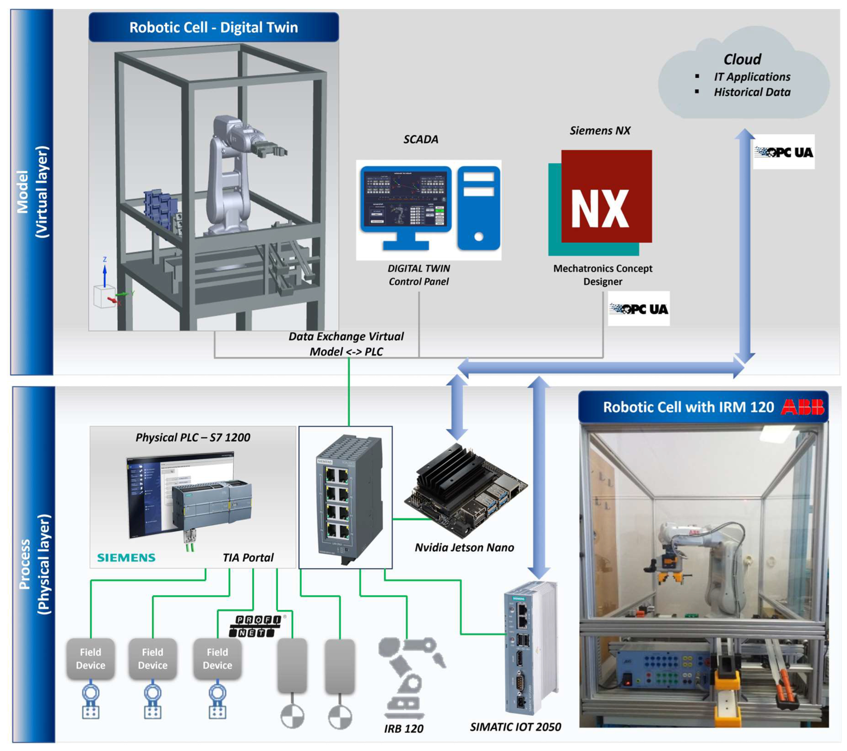
Figure 2.
6-DoF ABB 120 IRM Reachable Workspace.
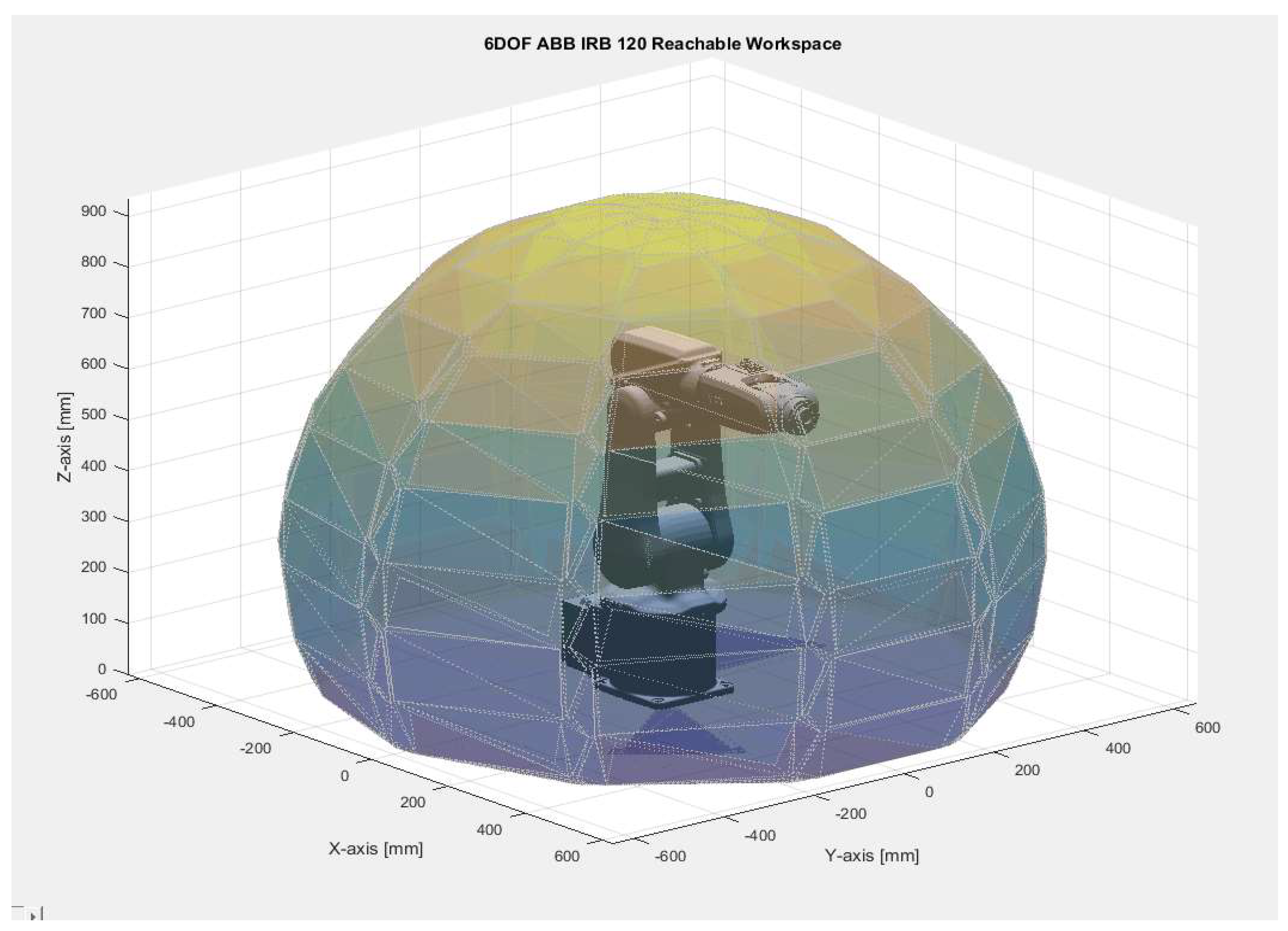
Figure 3.
ABB 120 IRM Joint angle and velocity limits.
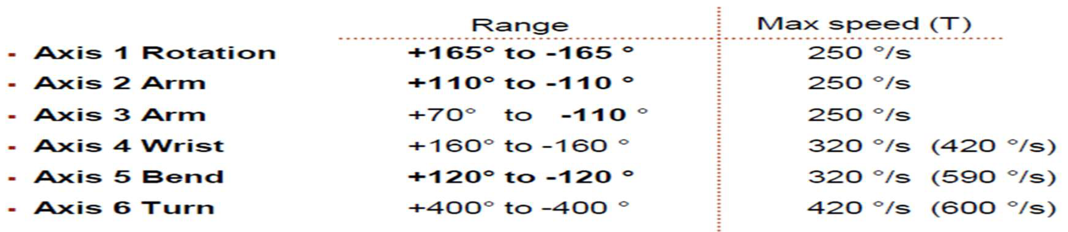
Figure 4.
Elementary rotations of frame Σuvw with respect to frame Σxyz: a)around X-axis; b) around Y-axis; c) around Z-axis.
Figure 4.
Elementary rotations of frame Σuvw with respect to frame Σxyz: a)around X-axis; b) around Y-axis; c) around Z-axis.
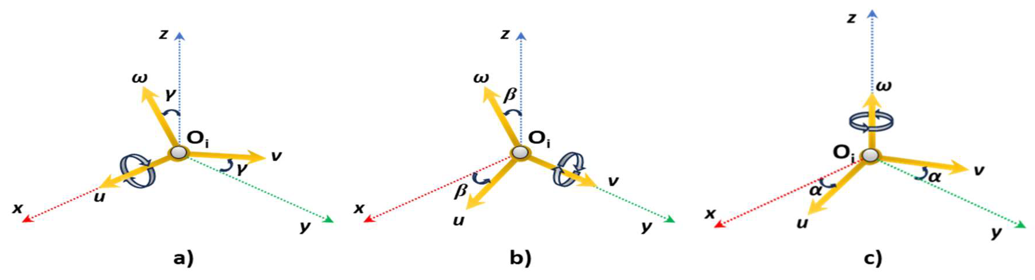
Figure 5.
D-H parameters for frame Σi starting from previous coordinate frame Σi-1.
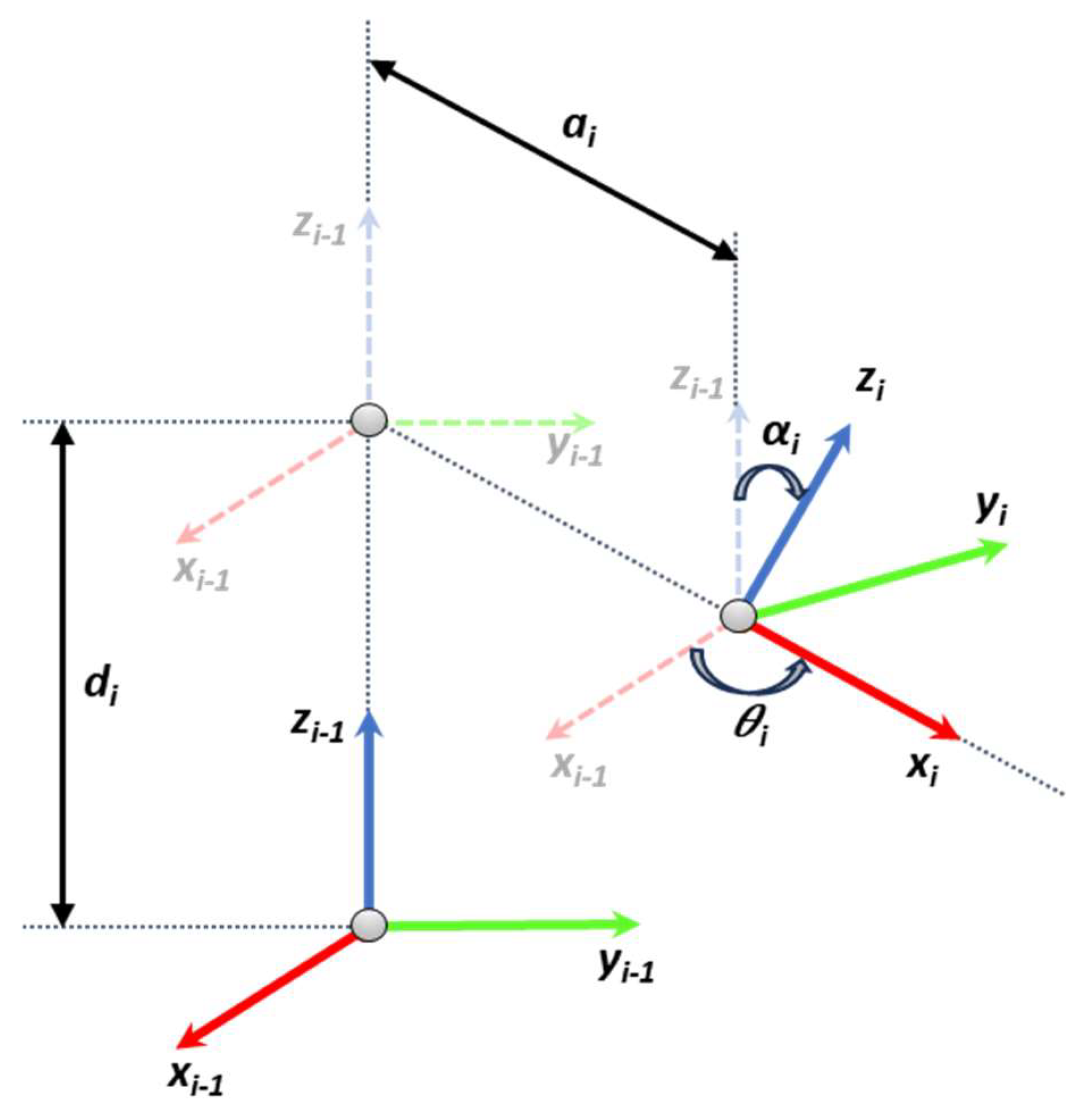
Figure 6.
D-H Frame assignment and parameters for ABB 120 IRM.
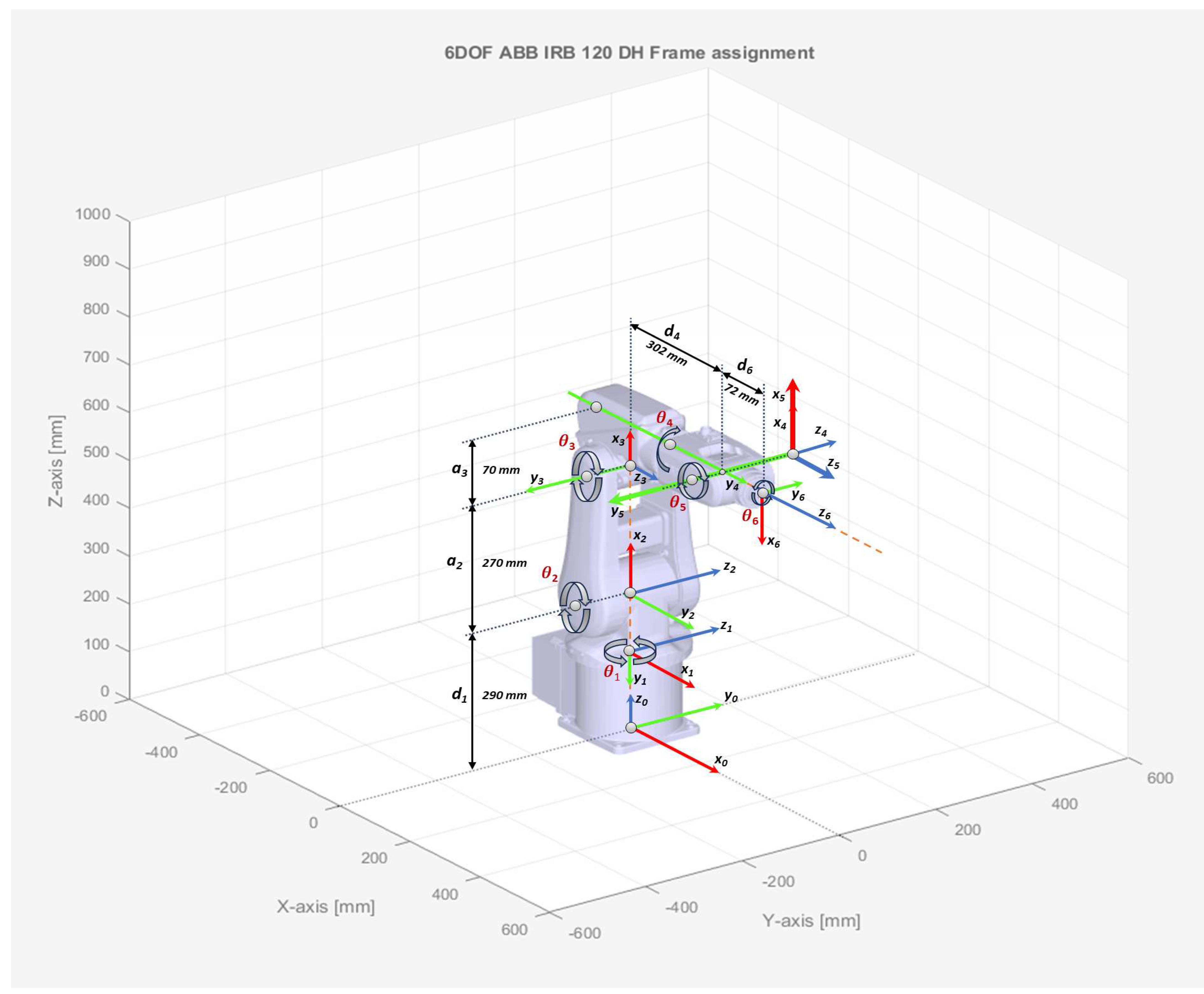
Figure 7.
ABB 120 IRM frame transformations according to D-H convention: a) frame Σ0 to frame Σ1; b) frame Σ1 to frame Σ2; c) frame Σ2 to frame Σ3 .
Figure 7.
ABB 120 IRM frame transformations according to D-H convention: a) frame Σ0 to frame Σ1; b) frame Σ1 to frame Σ2; c) frame Σ2 to frame Σ3 .
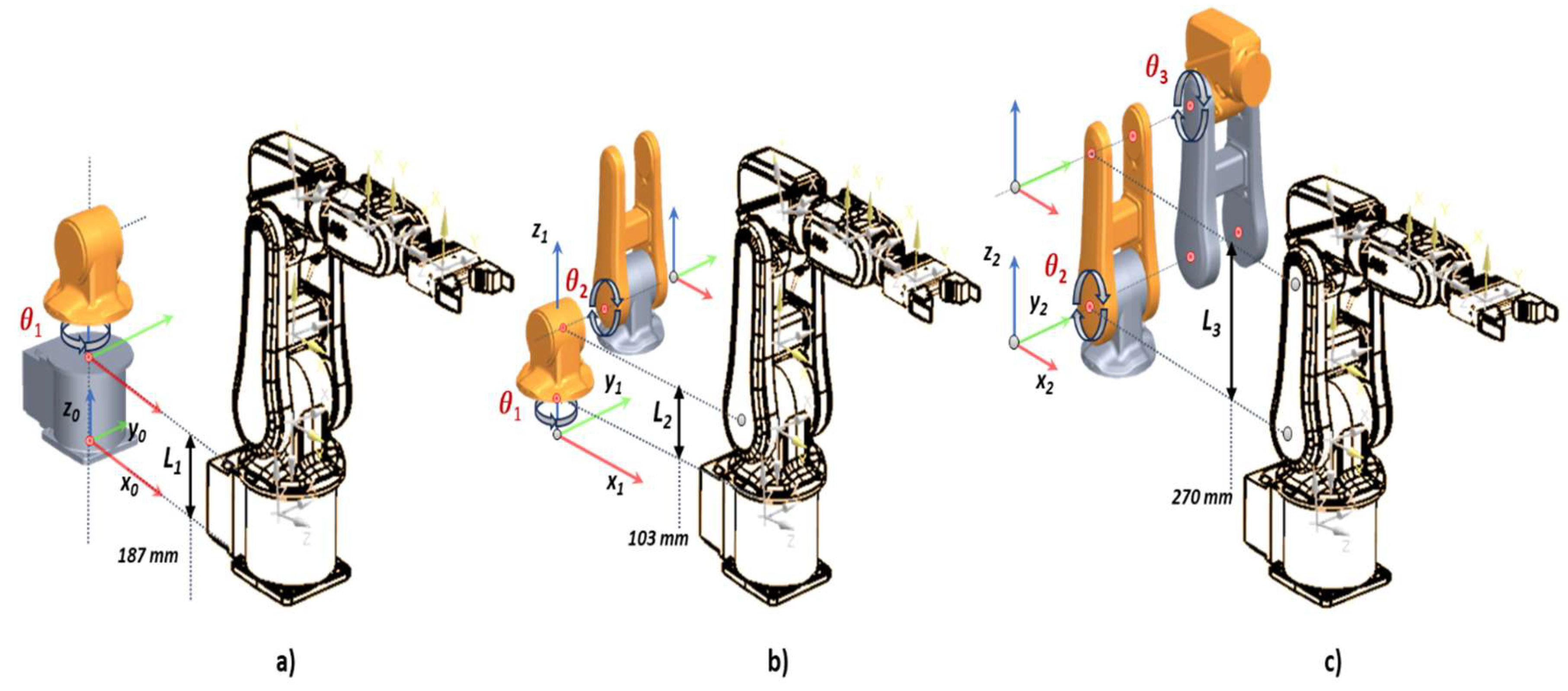
Figure 8.
ABB 120 IRM frame transformations according to D-H convention: a) frame Σ3 to frame Σ4; b) frame Σ4 to frame Σ5; c) frame Σ5 to frame Σ6 .
Figure 8.
ABB 120 IRM frame transformations according to D-H convention: a) frame Σ3 to frame Σ4; b) frame Σ4 to frame Σ5; c) frame Σ5 to frame Σ6 .
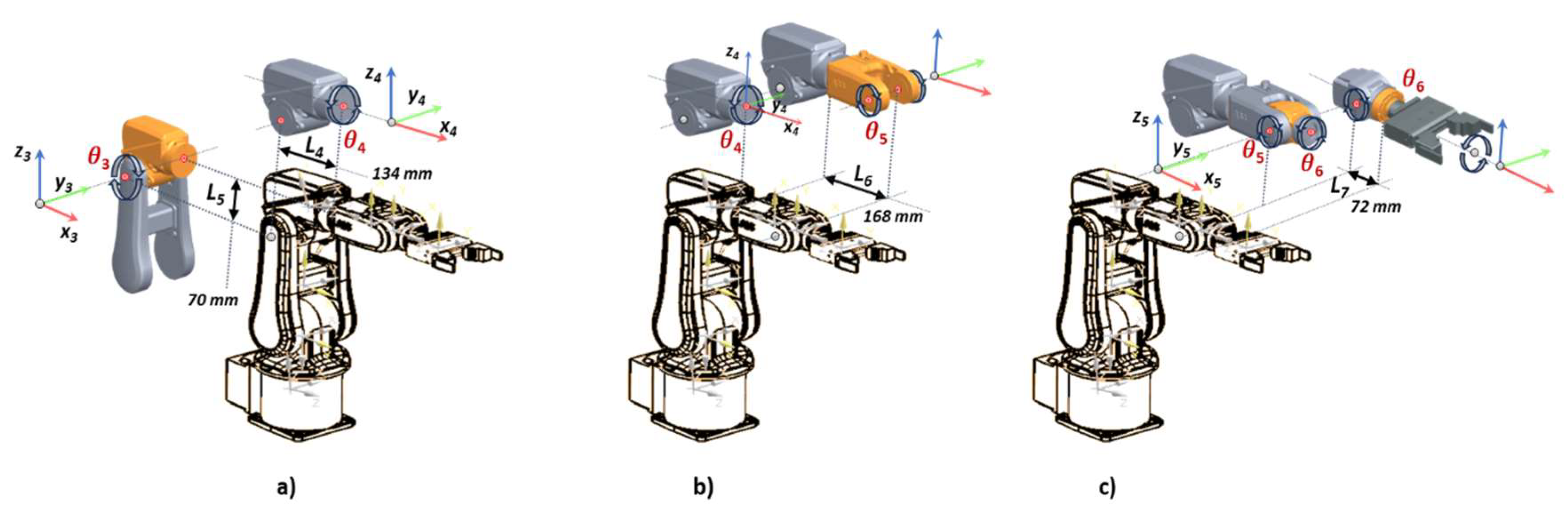
Figure 9.
Joint θ1 geometrical solution approach.
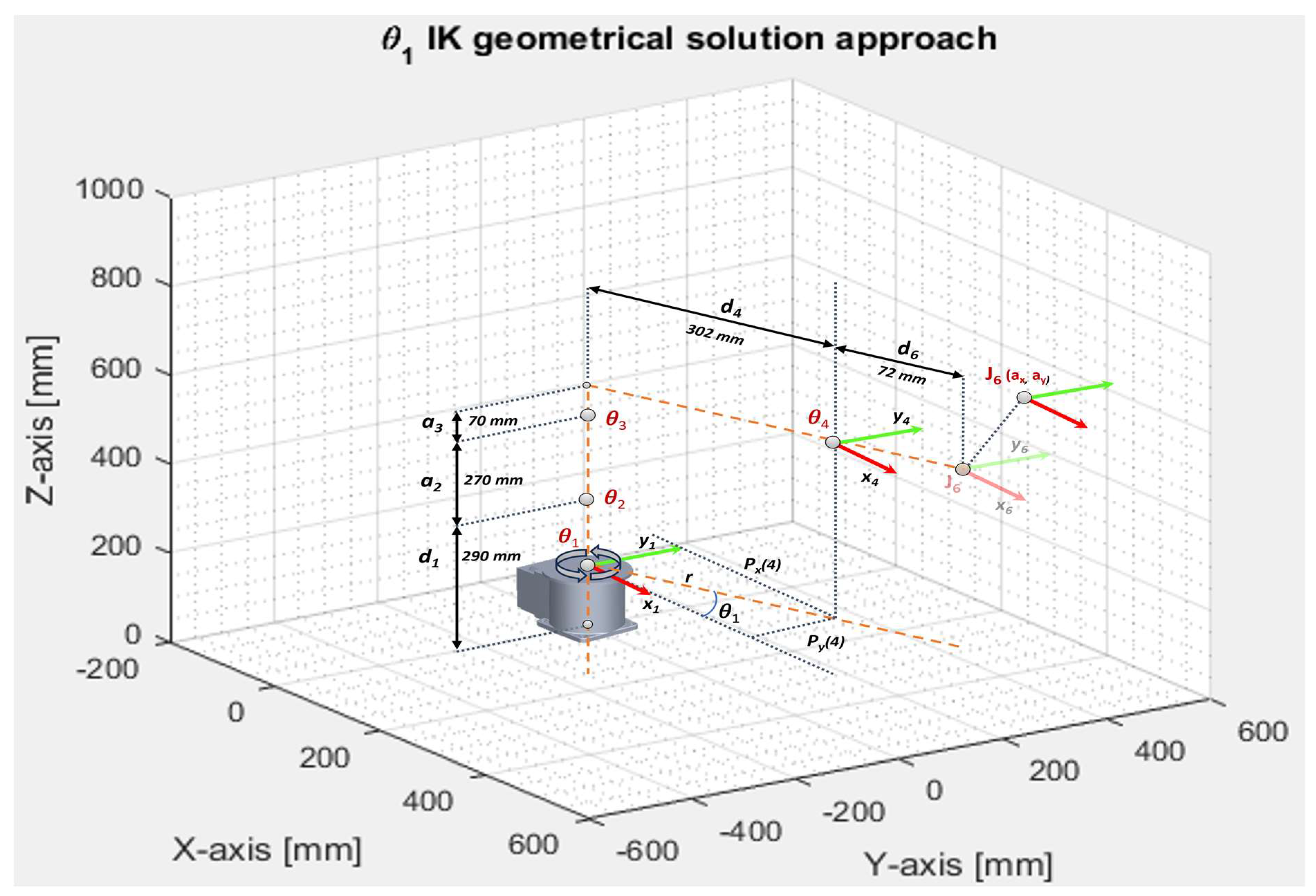
Figure 10.
Joints θ2 and θ3 geometrical solution approach.
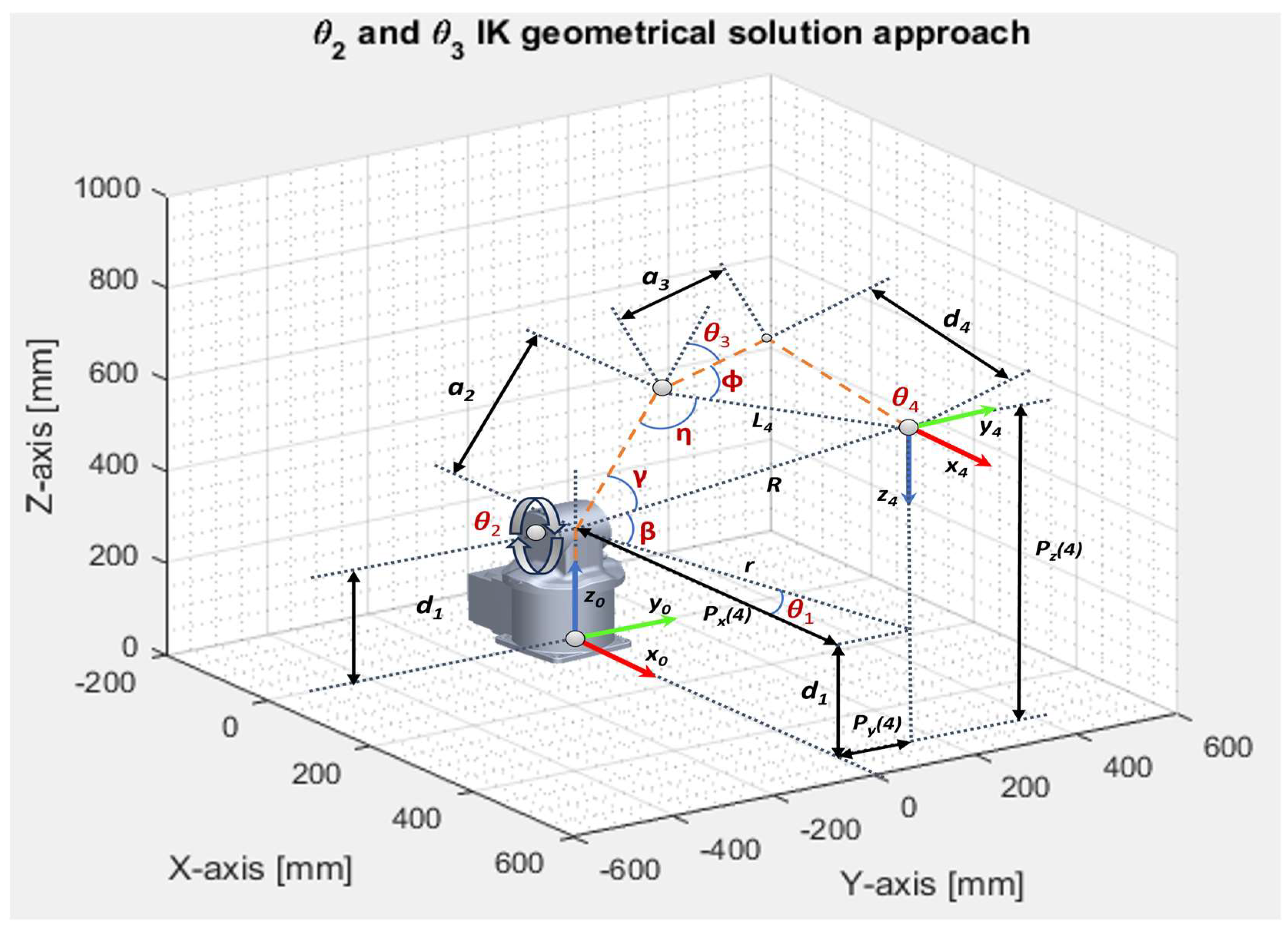
Figure 11.
ABB 120 IRM Linear motion space simulation with Inverse Kinematics: a) joint angle; b) joint angle; c) joint angle; d) joint angle.
Figure 11.
ABB 120 IRM Linear motion space simulation with Inverse Kinematics: a) joint angle; b) joint angle; c) joint angle; d) joint angle.
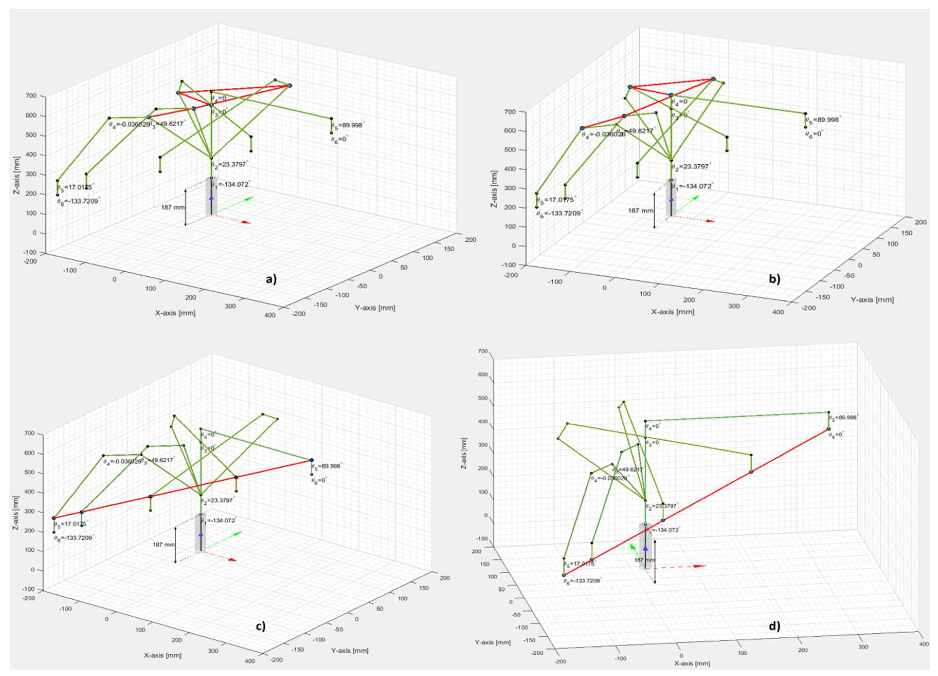
Figure 12.
Node-RED task planning for the assembly of WP1 or WP2.
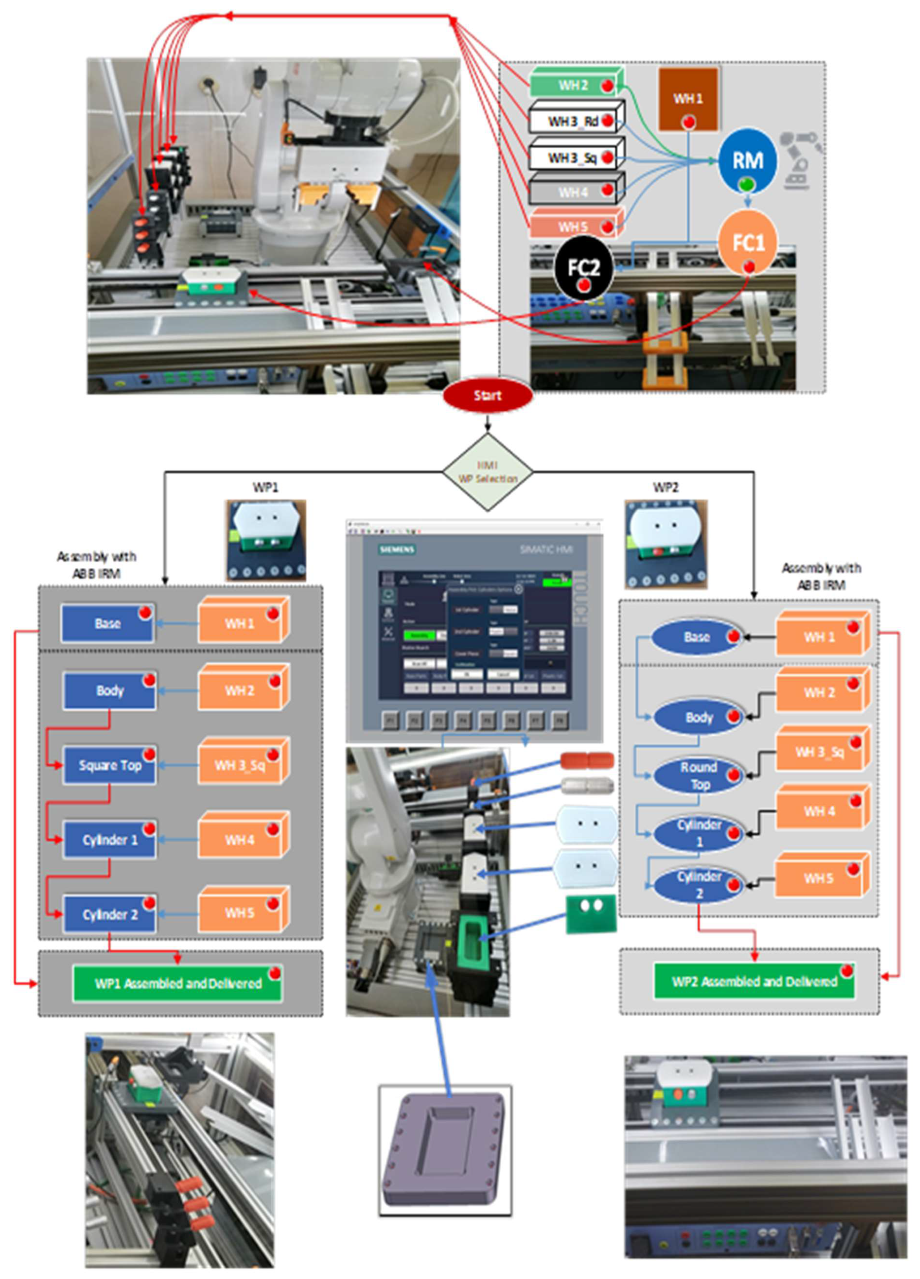
Figure 13.
STPN model for assembly of WP1 or WP2.
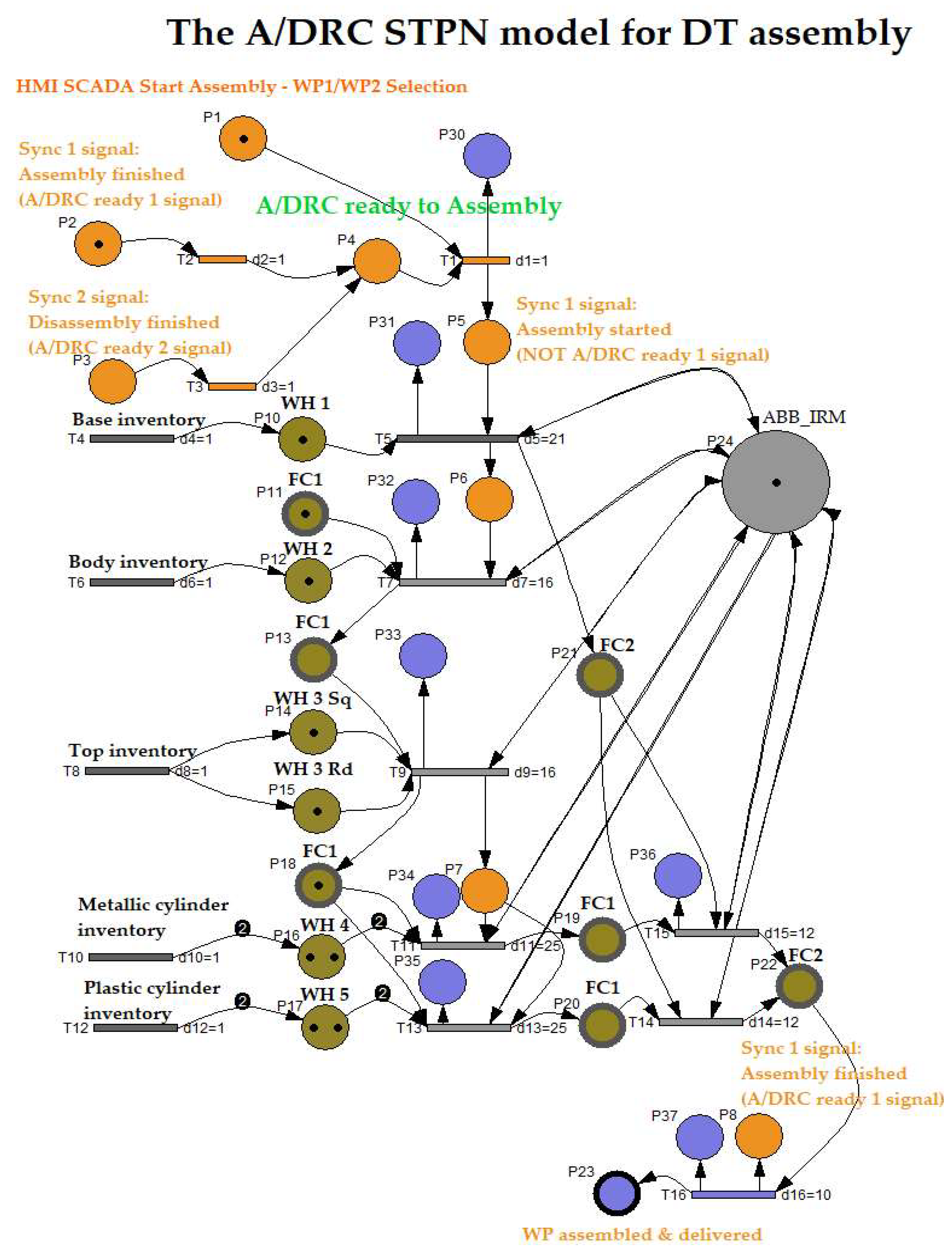
Figure 14.
Sirphyco simulation of STPN model for the assembly of WP1 or WP2.
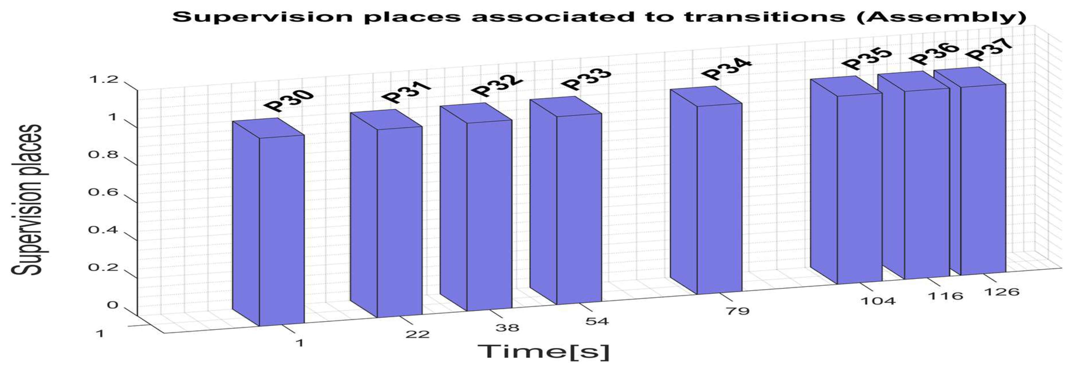
Figure 15.
Node-RED task planning for disassembly of WP1 or WP2.
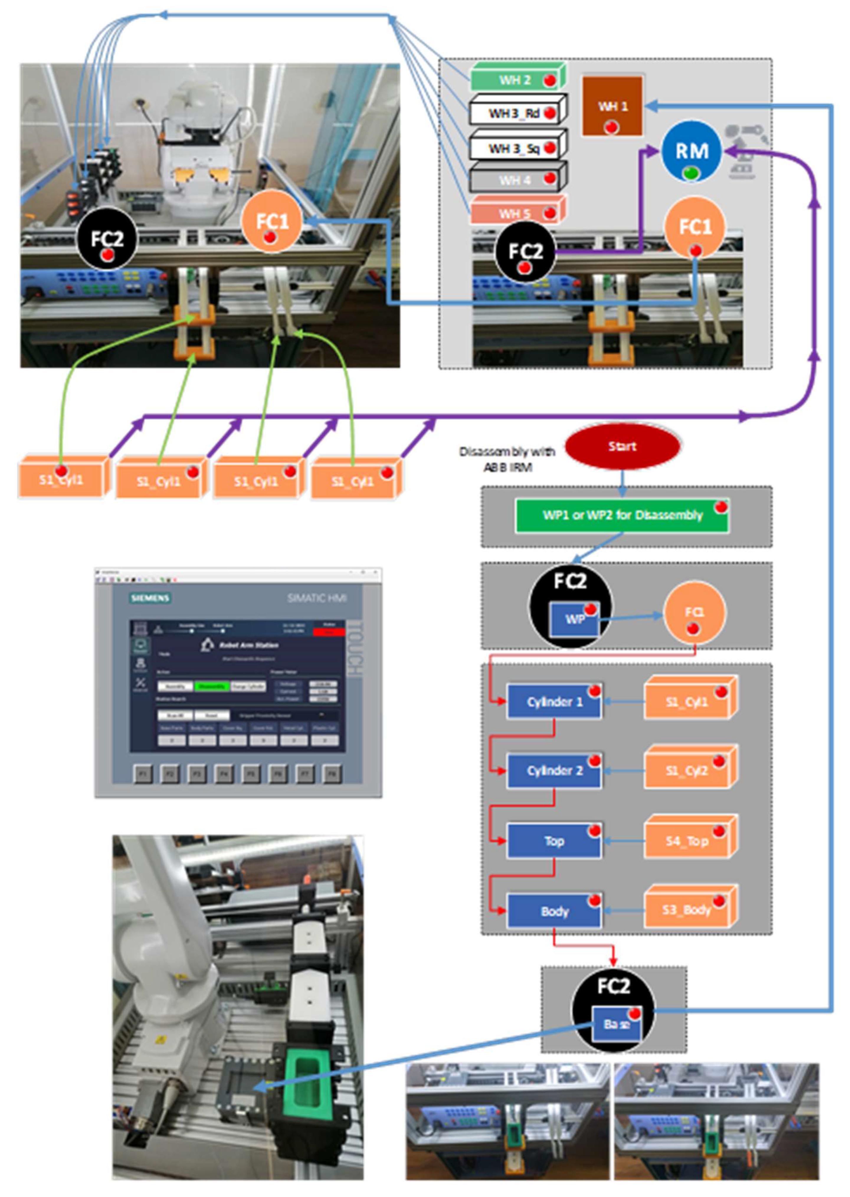
Figure 18.
DT 3D Model designing in NX Mechatronics Concept Designer.
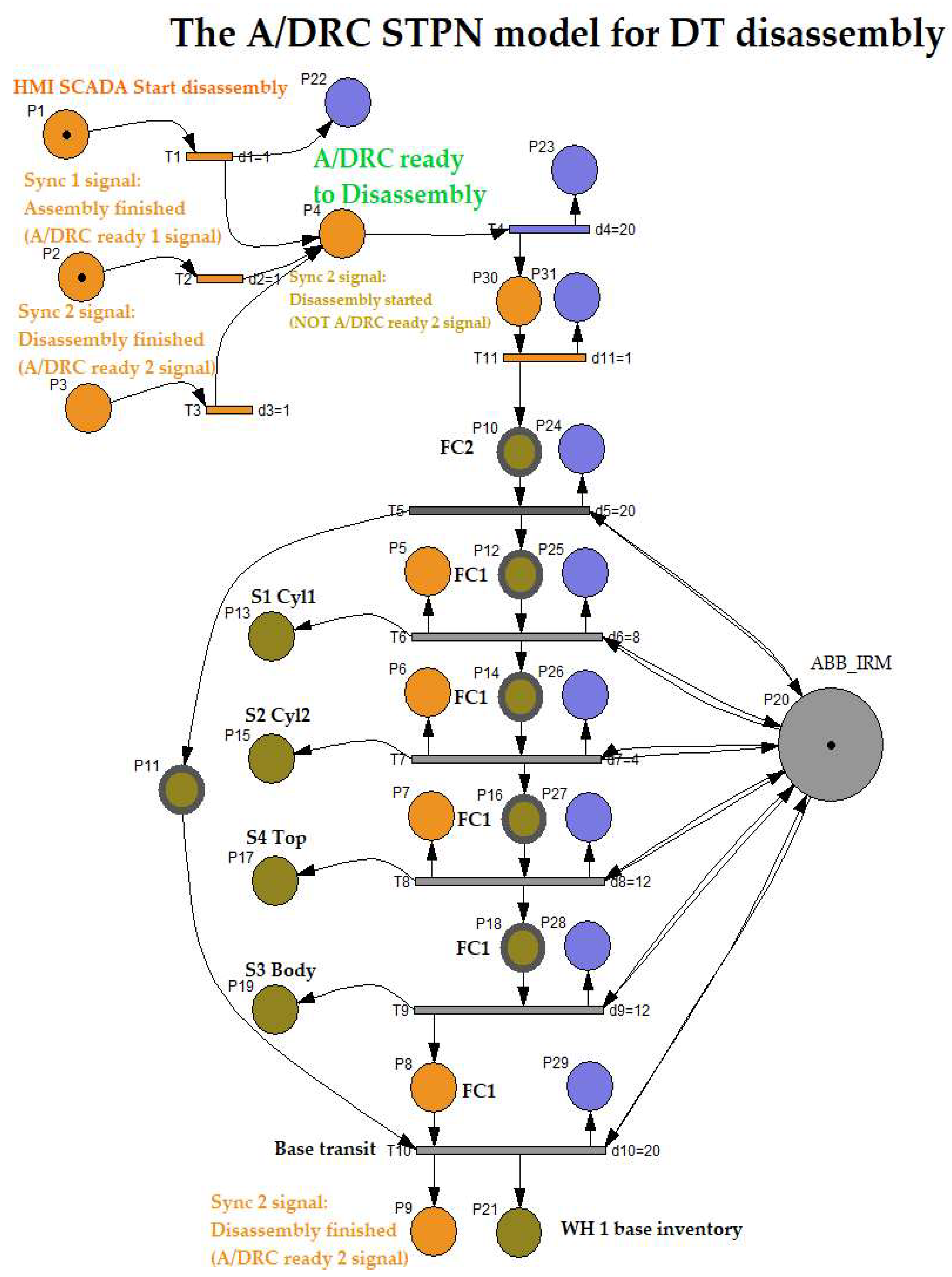
Figure 16.
STPN model for disassembly of WP1 or WP2.
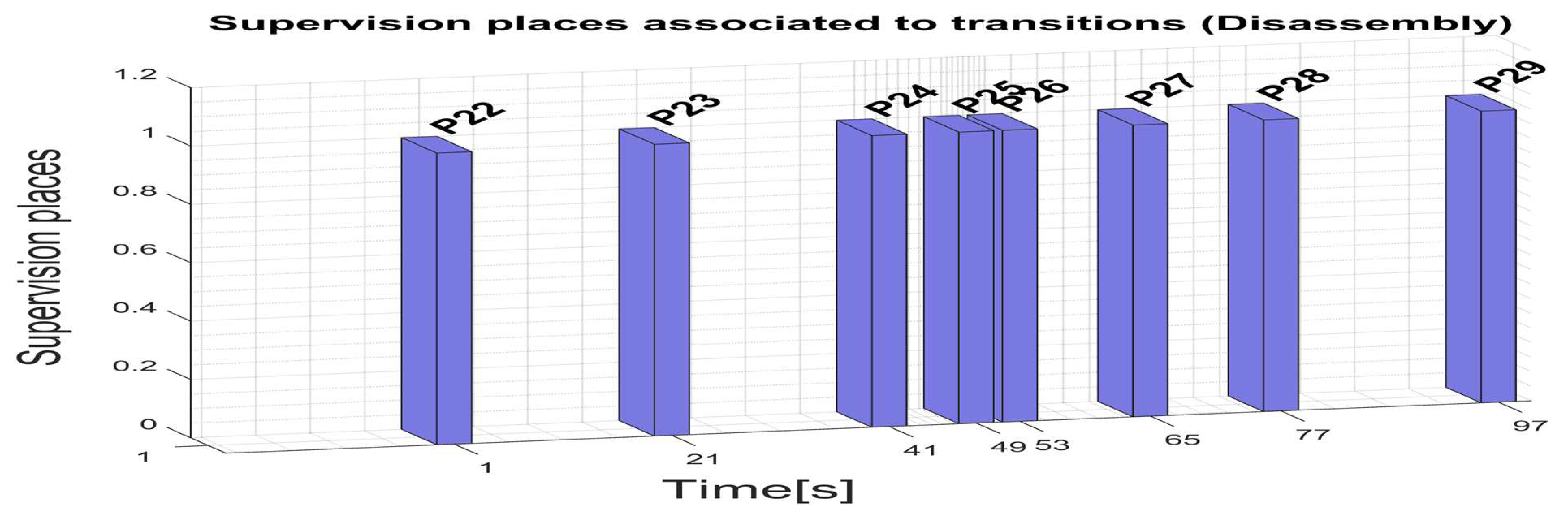
Figure 17.
Sirphyco simulation of STPN model for the disassembly.
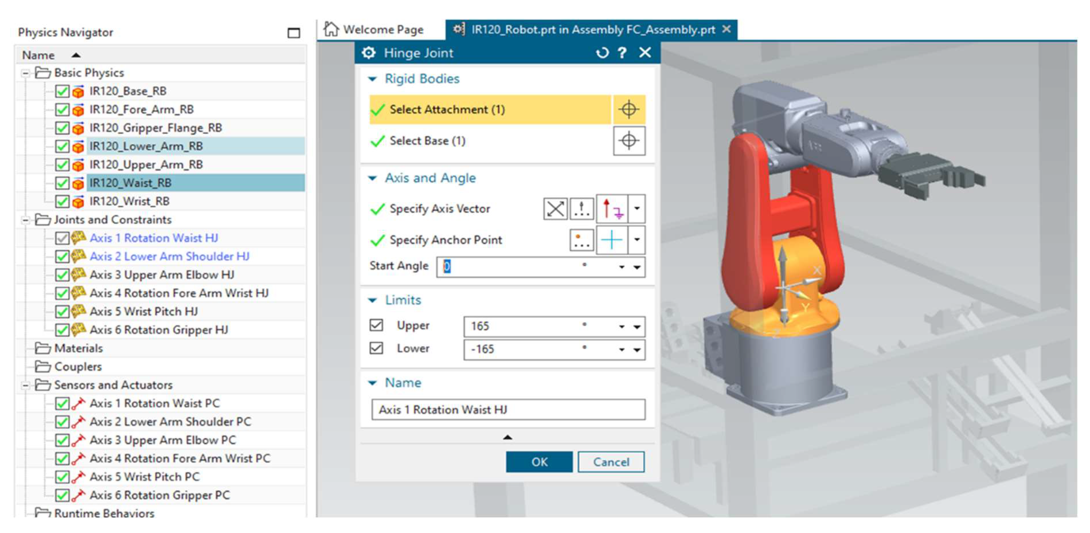
Figure 19.
Cloud and VPN based Control Multilevel Architecture.
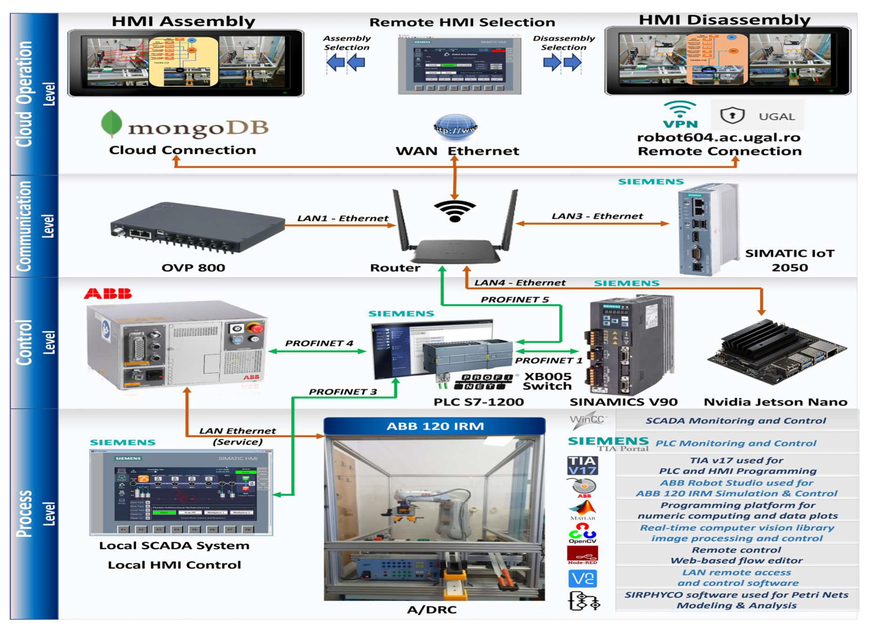
Figure 20.
Siemens PLC Main program OB1 functionality chart and structure.
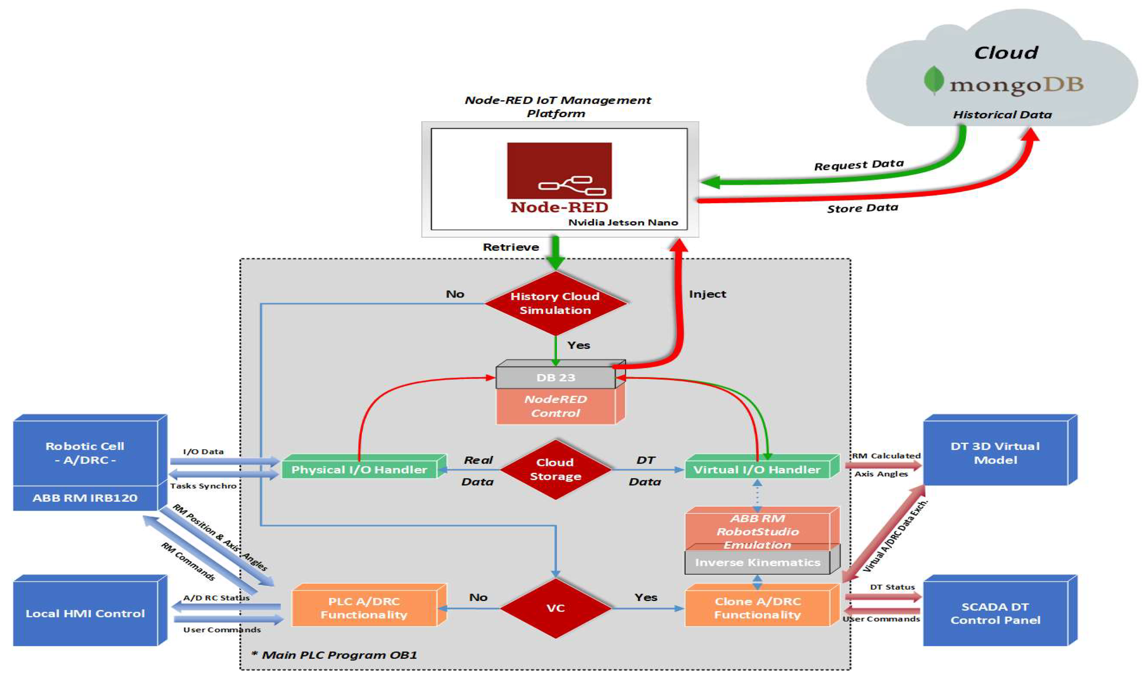
Figure 21.
Siemens PLC function blocks for inverse kinematics: a) θ2 joint angle calculation; b) θ2 and θ3 joint angles calculation; c) θ4, θ5, θ6 joint angles calculation; d) inverse kinematic solution selection; e) inverse kinematics 6-DOF RM solution for a given robtarget.
Figure 21.
Siemens PLC function blocks for inverse kinematics: a) θ2 joint angle calculation; b) θ2 and θ3 joint angles calculation; c) θ4, θ5, θ6 joint angles calculation; d) inverse kinematic solution selection; e) inverse kinematics 6-DOF RM solution for a given robtarget.
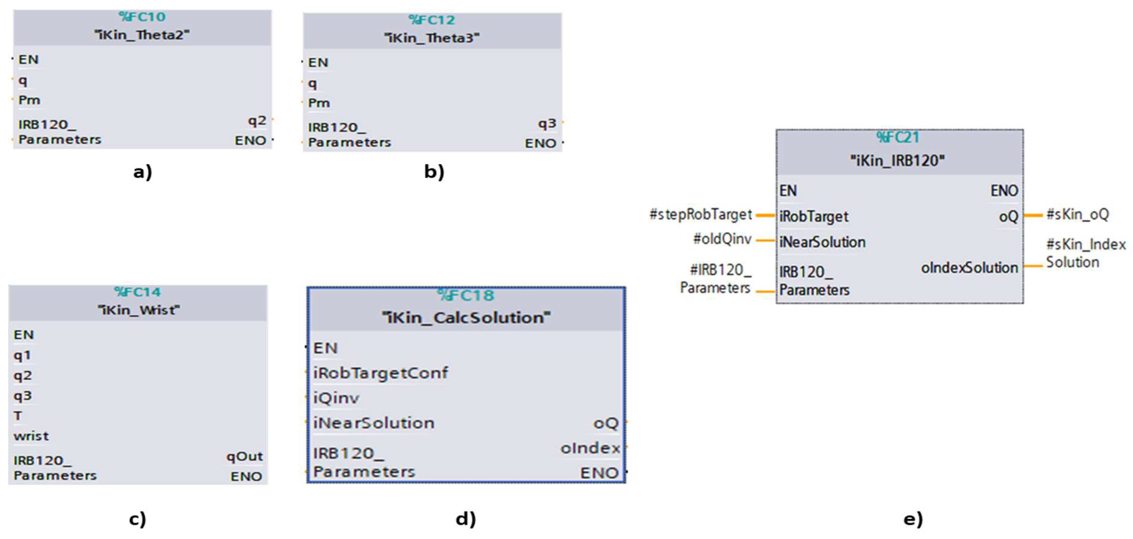
Figure 22.
PLC function block design algorithm for MoveL linear motion solution through path segmentation.
Figure 22.
PLC function block design algorithm for MoveL linear motion solution through path segmentation.
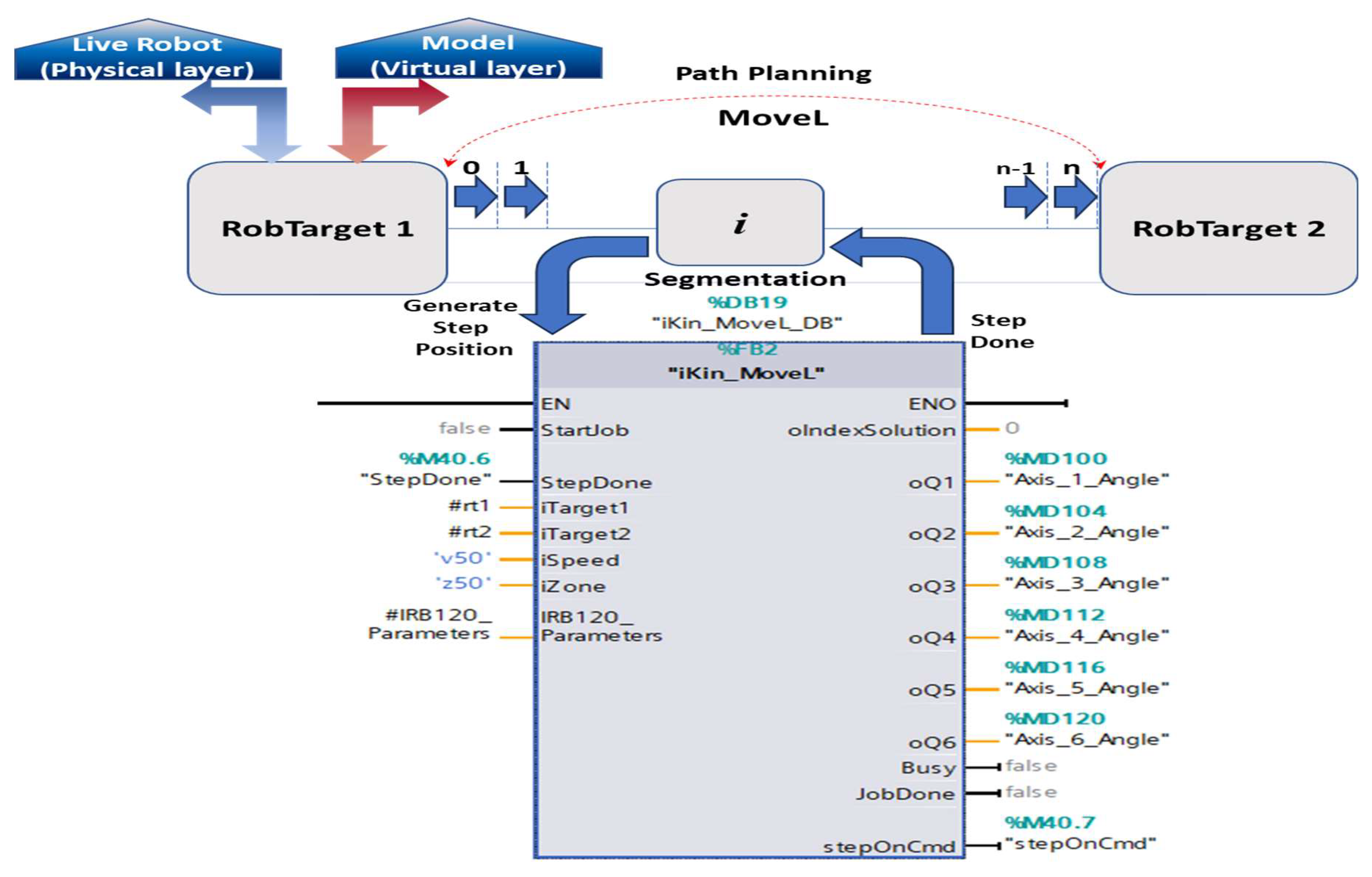
Figure 23.
Siemens PLC function block for Trajectory path generation implementing Cubic Polynomials smooth function.
Figure 23.
Siemens PLC function block for Trajectory path generation implementing Cubic Polynomials smooth function.
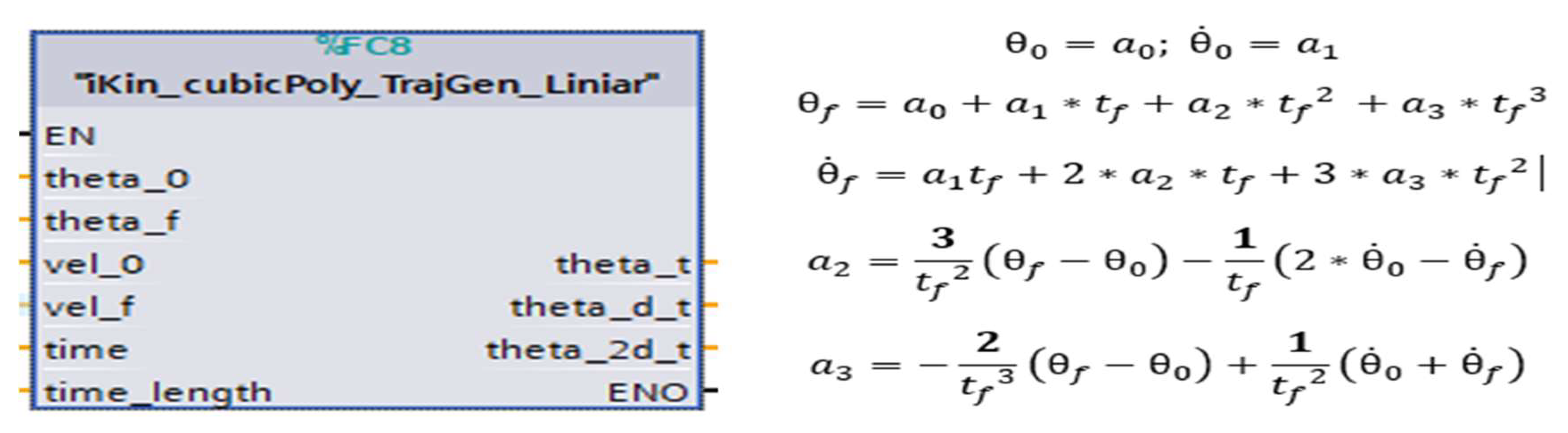
Figure 24.
RM task space trajectory-Linear Motion MATLAB plot validation: a) Top view; b) Side View.
Figure 24.
RM task space trajectory-Linear Motion MATLAB plot validation: a) Top view; b) Side View.
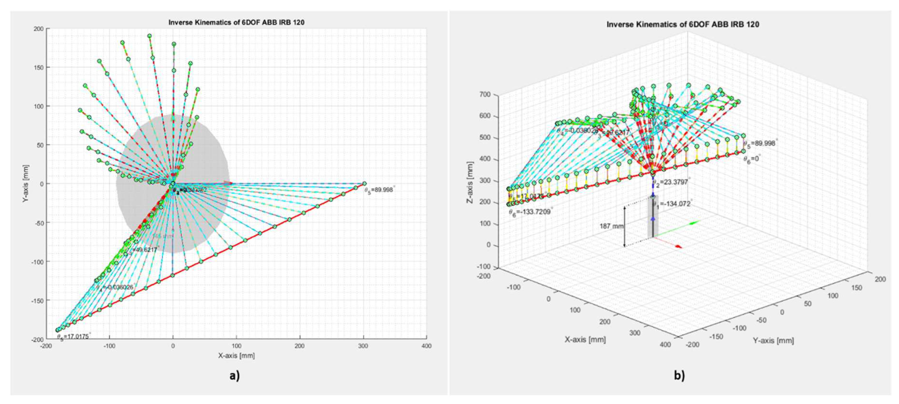
Figure 25.
Hardware-in-the-loop (HIL) Virtual Commissioning Concept.
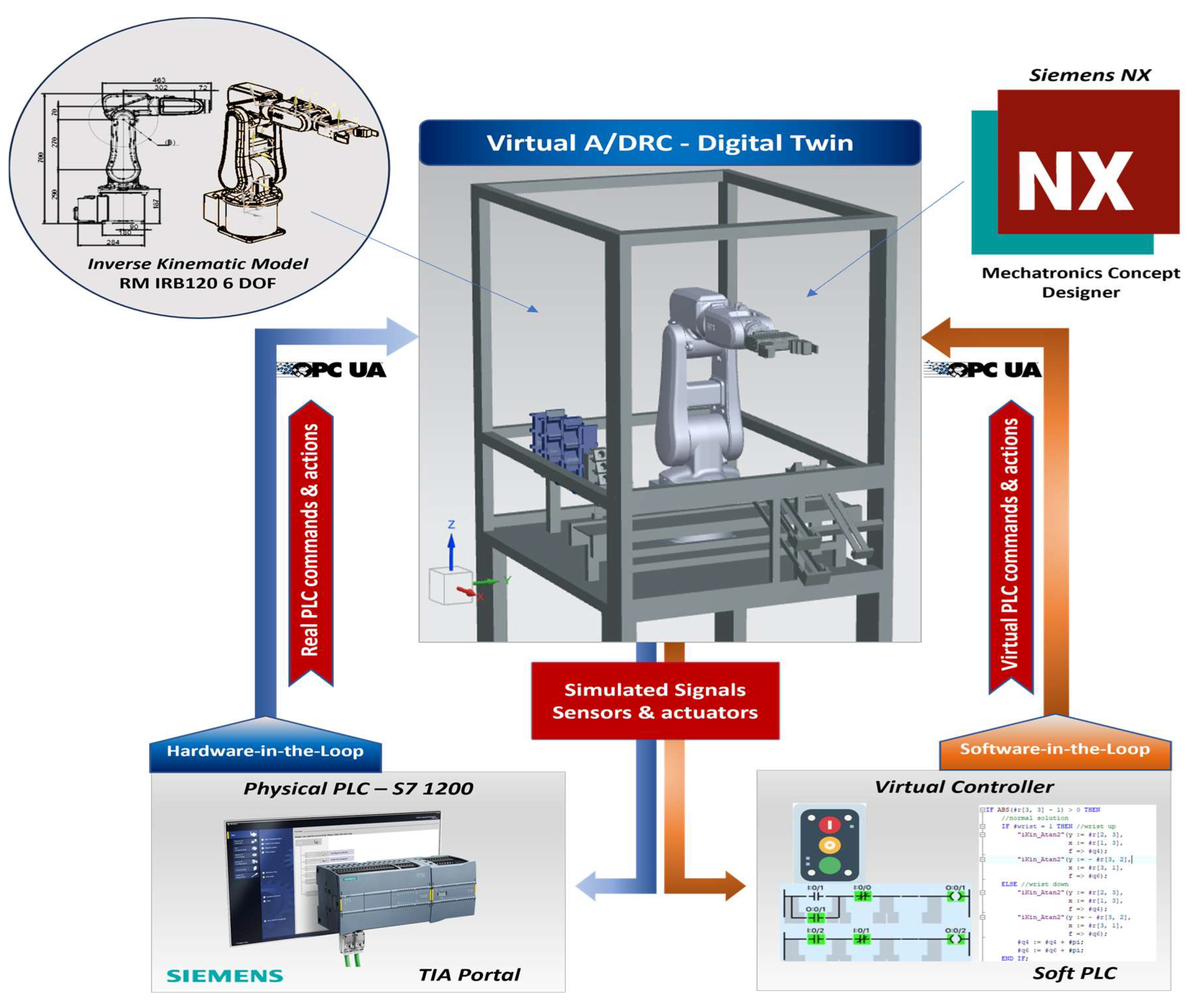
Figure 26.
Inverse kinematics calculation and testing and DT simulation SCADA mimic.
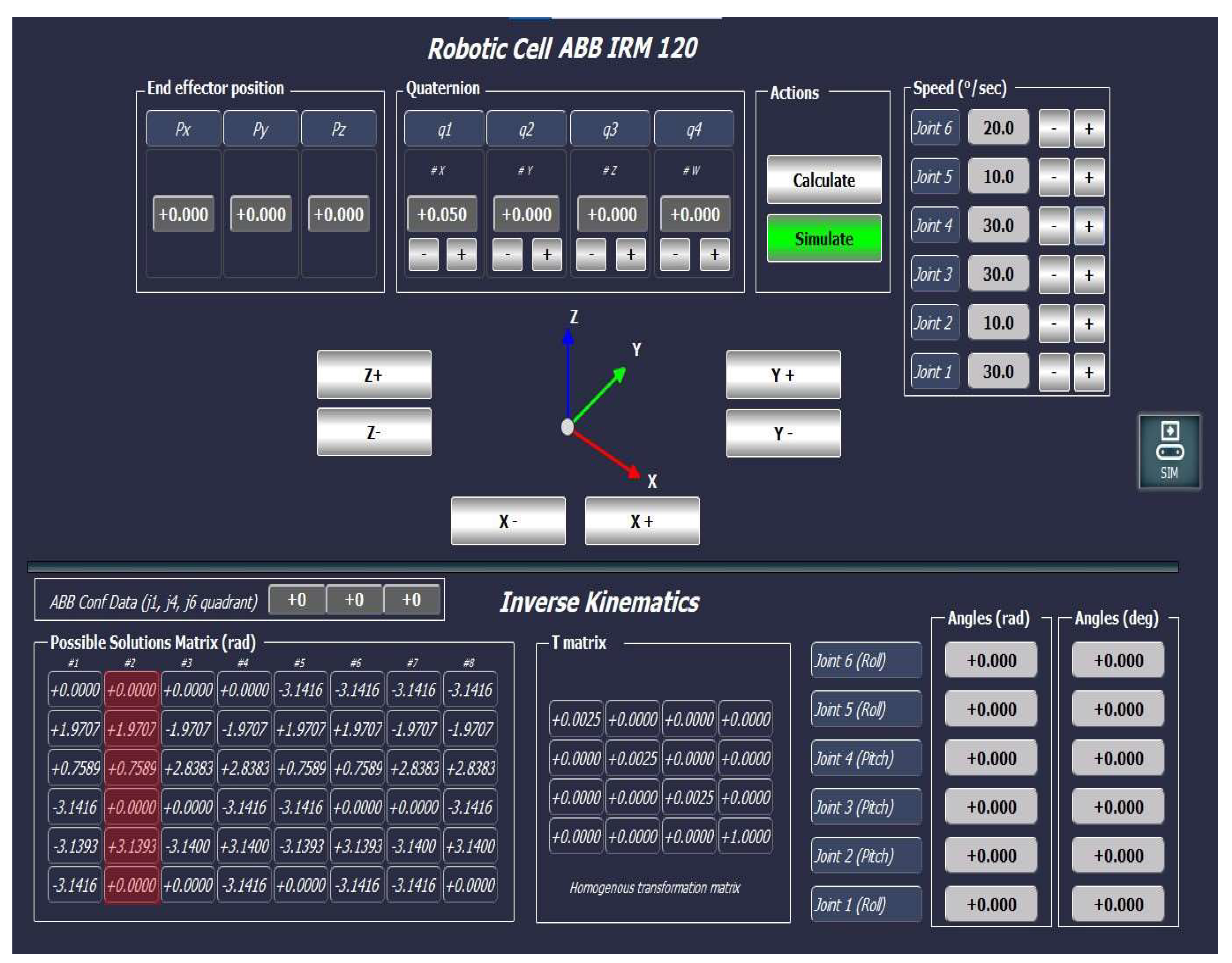
Figure 27.
SCADA DT operations control panel and motion control.
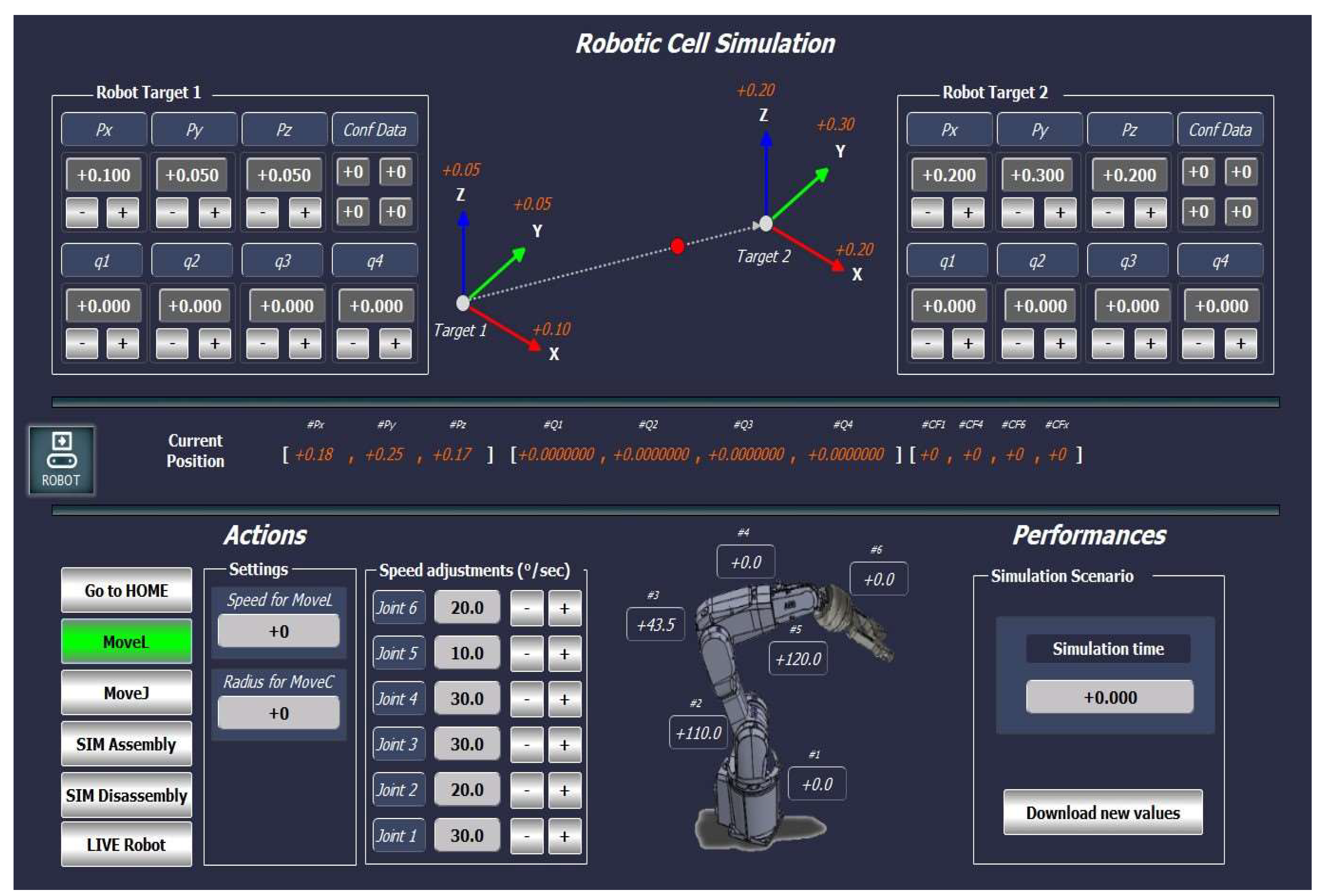
Figure 28.
SCADA DT History Cloud Simulation.
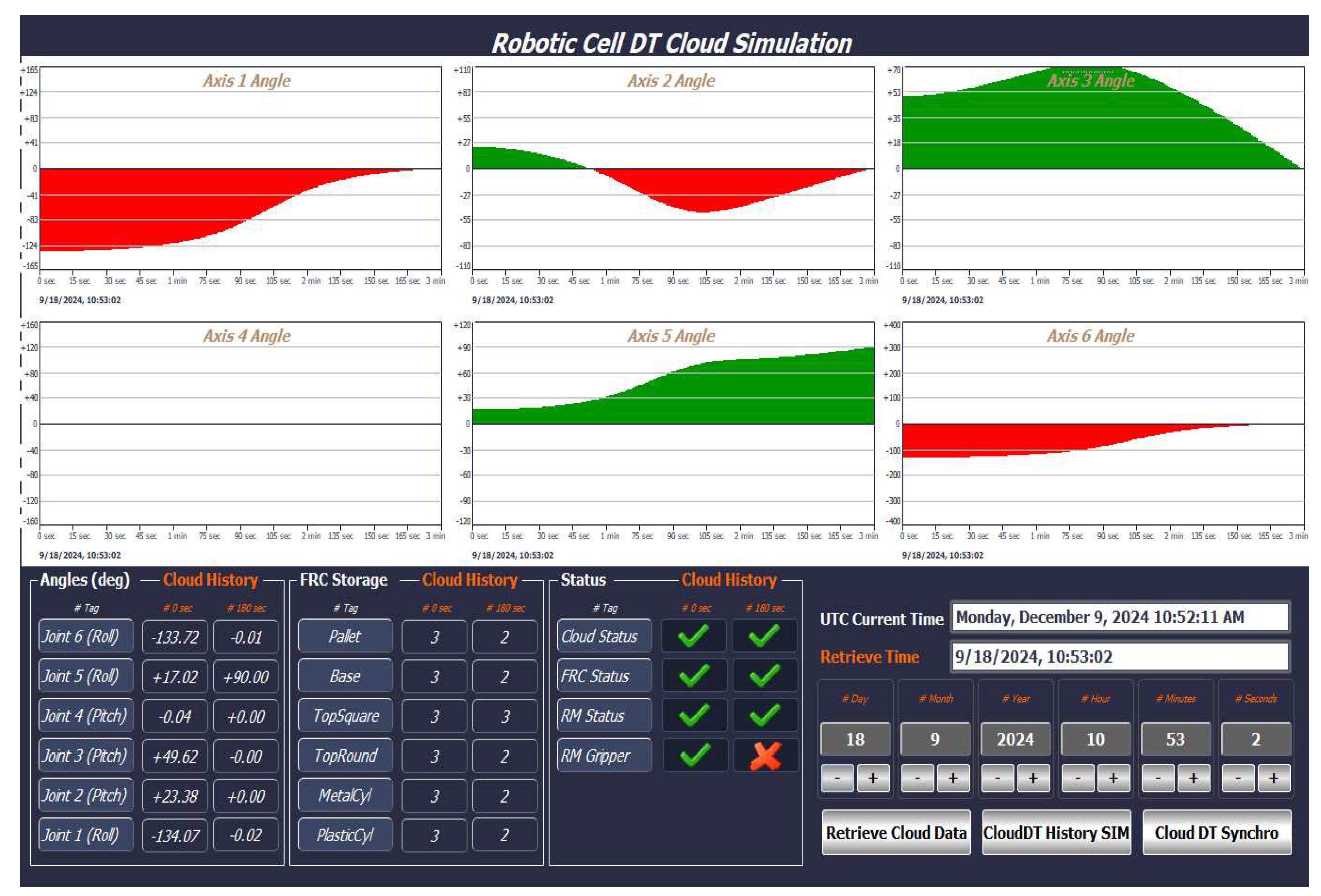
Figure 29.
SCADA DT Cloud Data Storage.
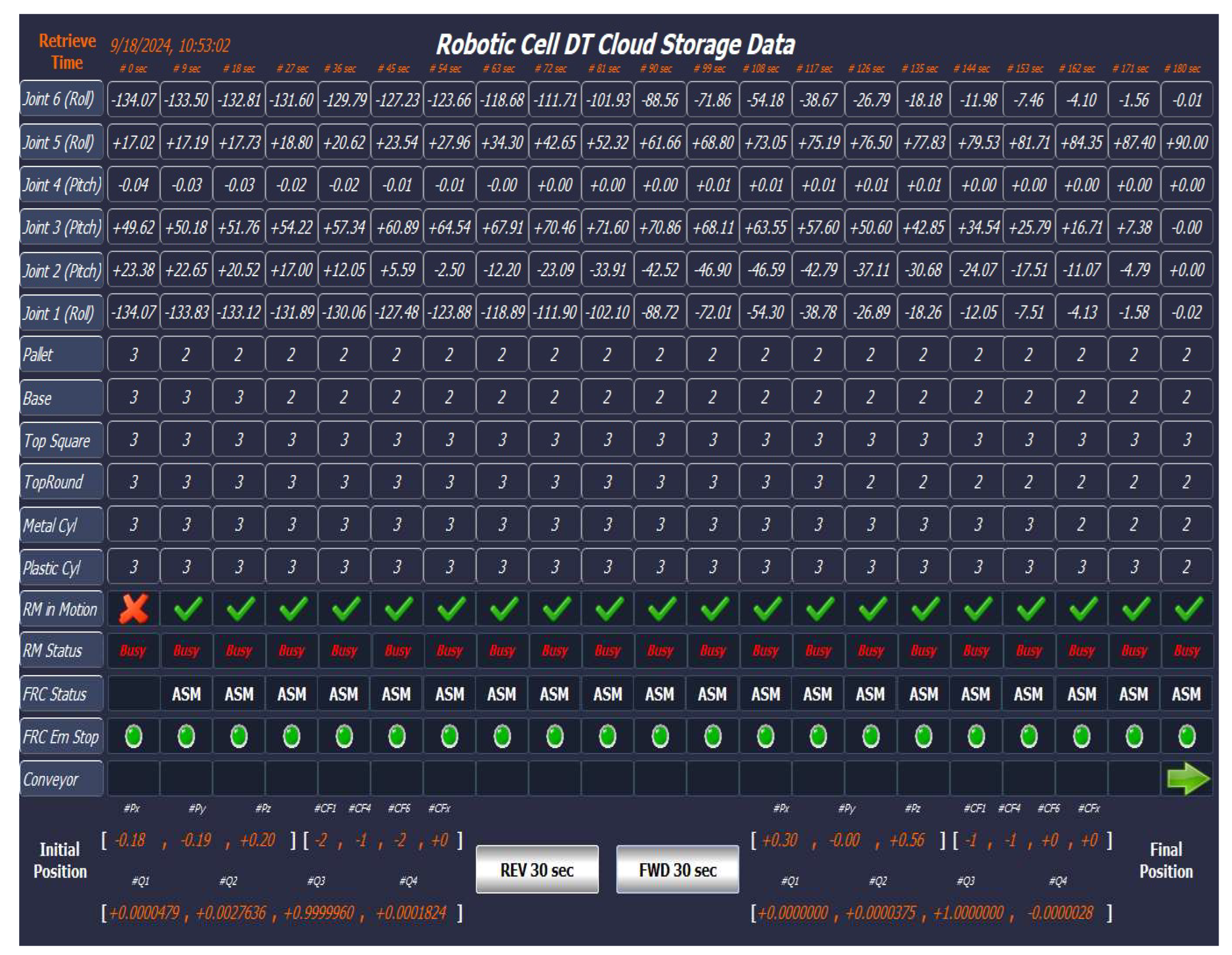
Figure 30.
General system setup for model-driven DT using IoT.
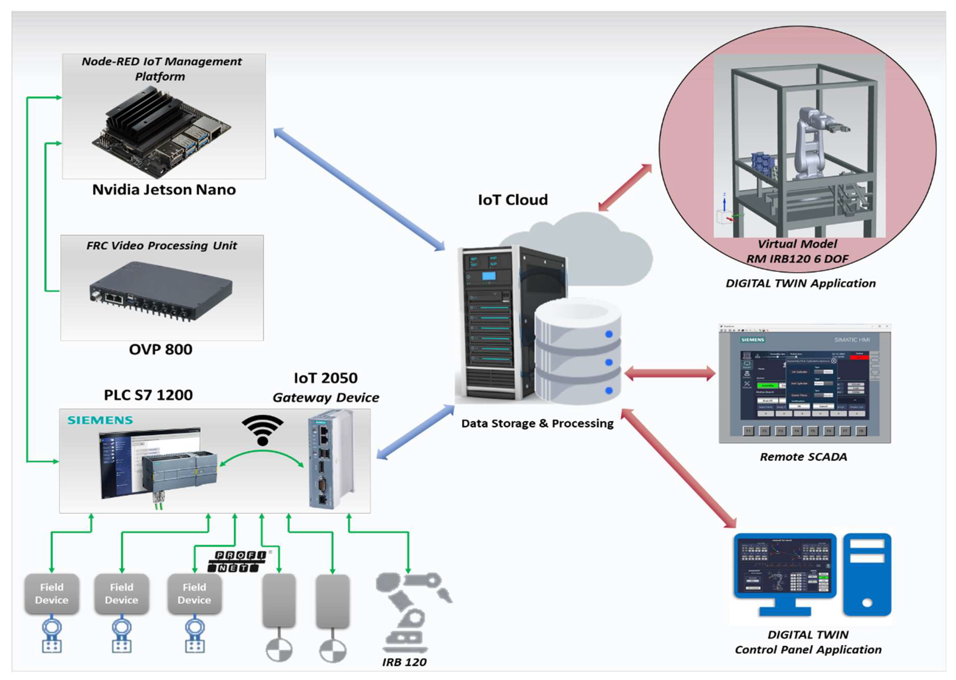
Figure 31.
Node-RED Cloud-PLC flow interaction.
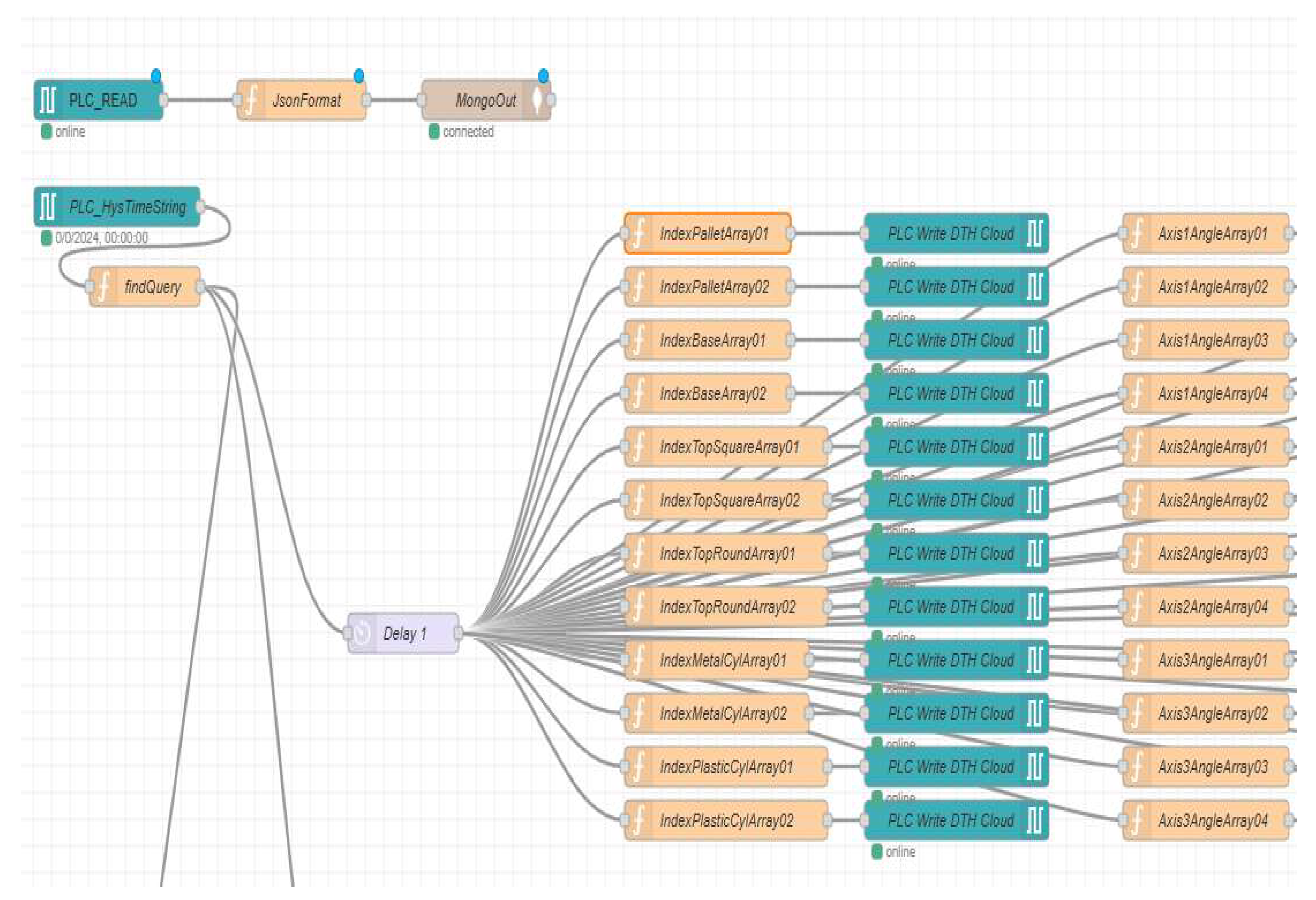
Figure 32.
Physical system and DT MoveL linear motion trajectory evolution.
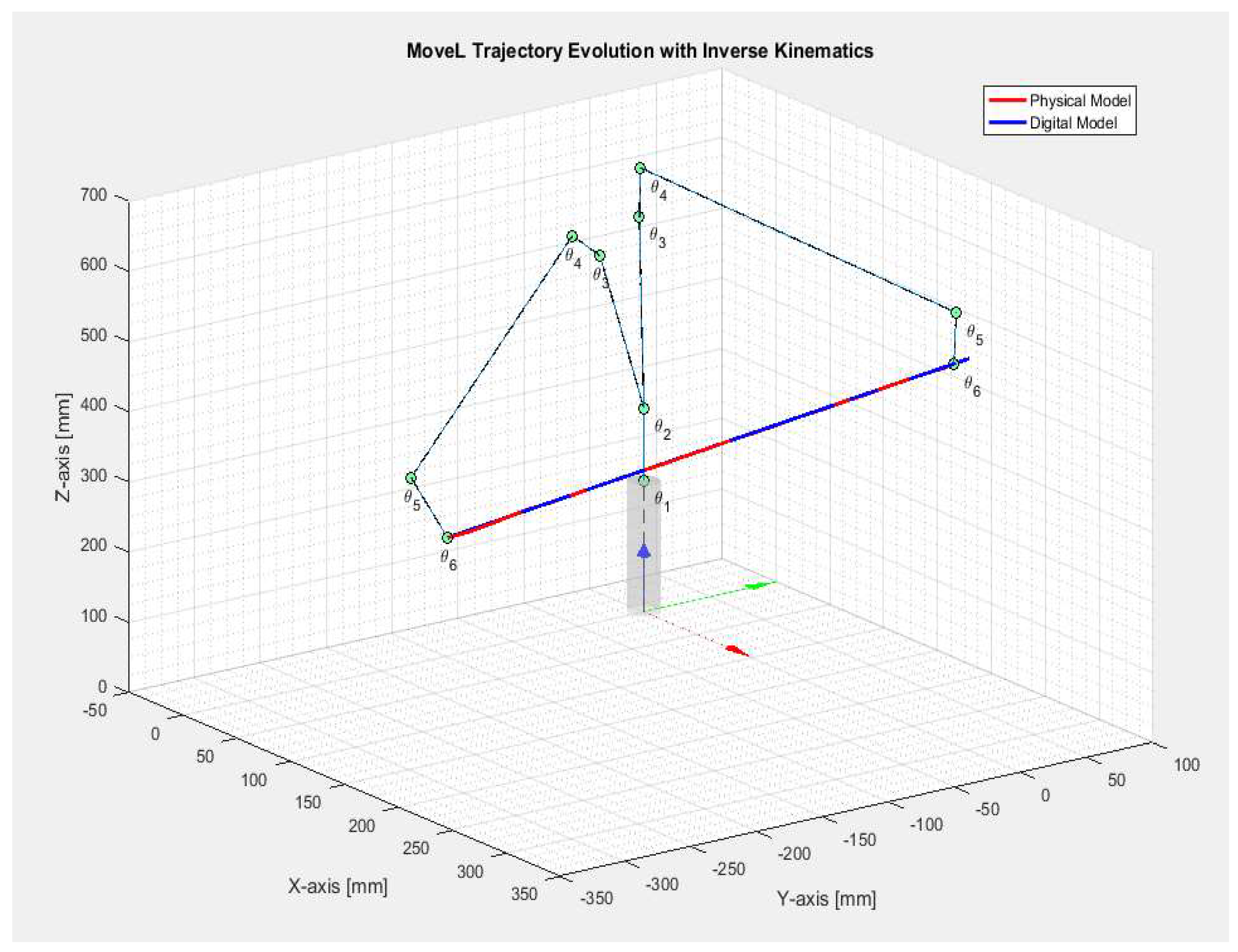
Figure 33.
DT RM x-axis error for MoveL linear motion to home position.
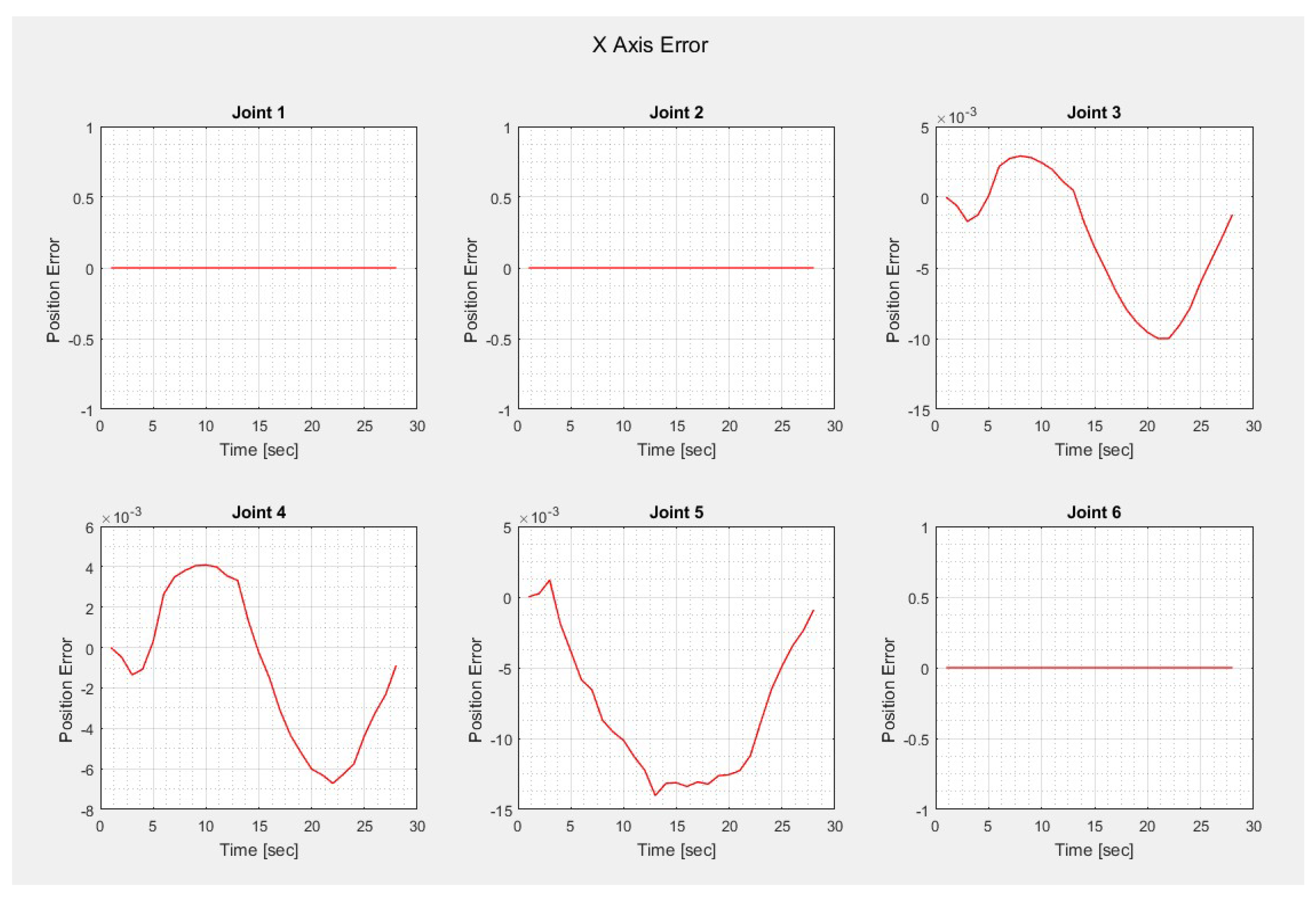
Figure 34.
DT RM y-axis error for MoveL linear motion to home position.
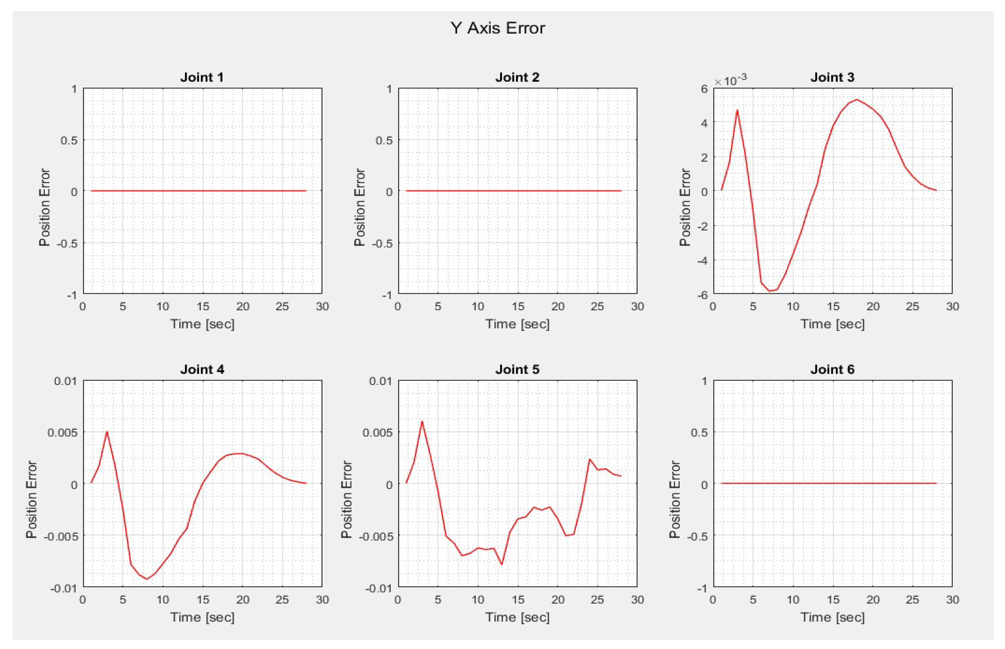
Figure 35.
DT RM z-axis error for MoveL linear motion to home position.
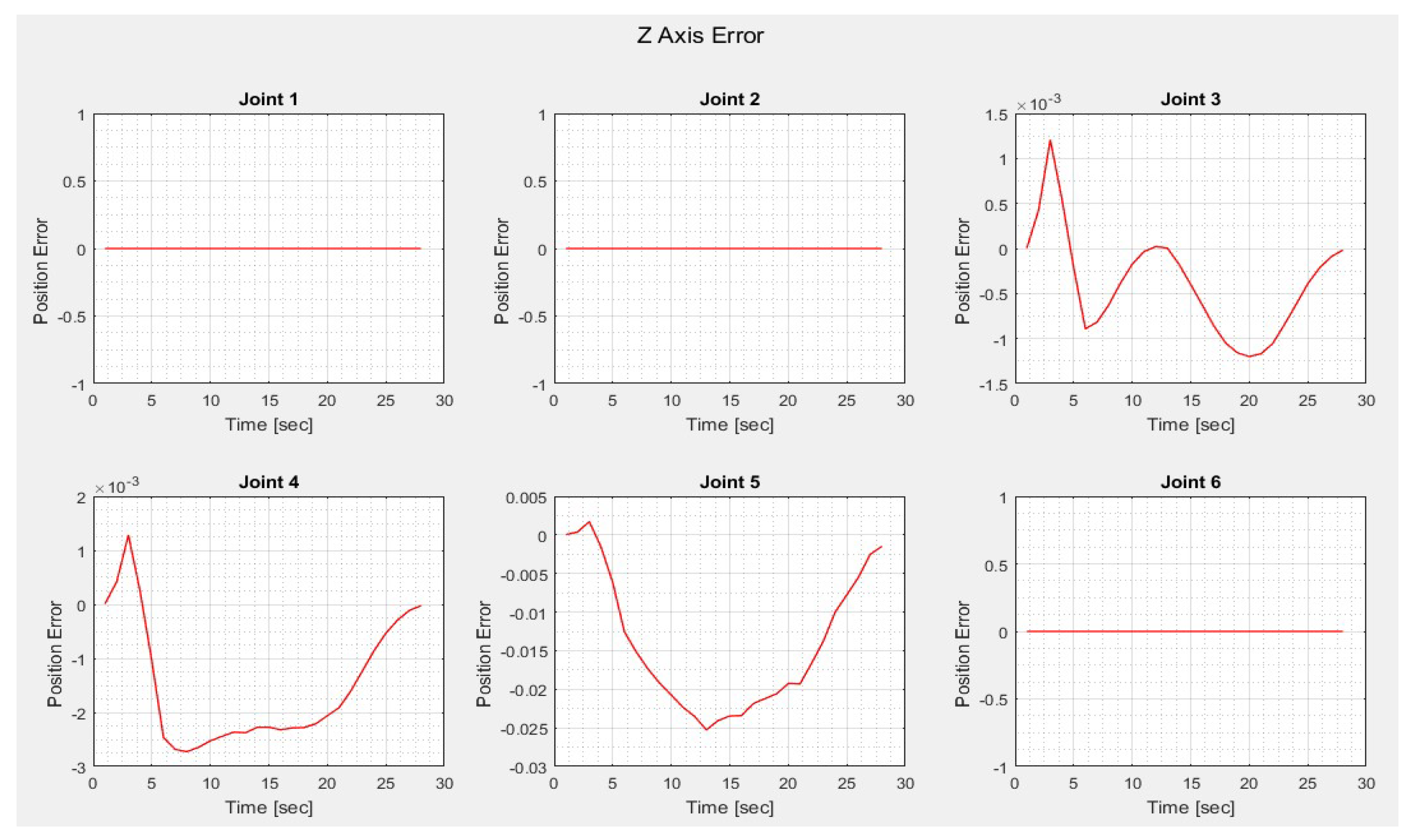
Figure 36.
RM Joint angles for MoveL linear motion to home position.
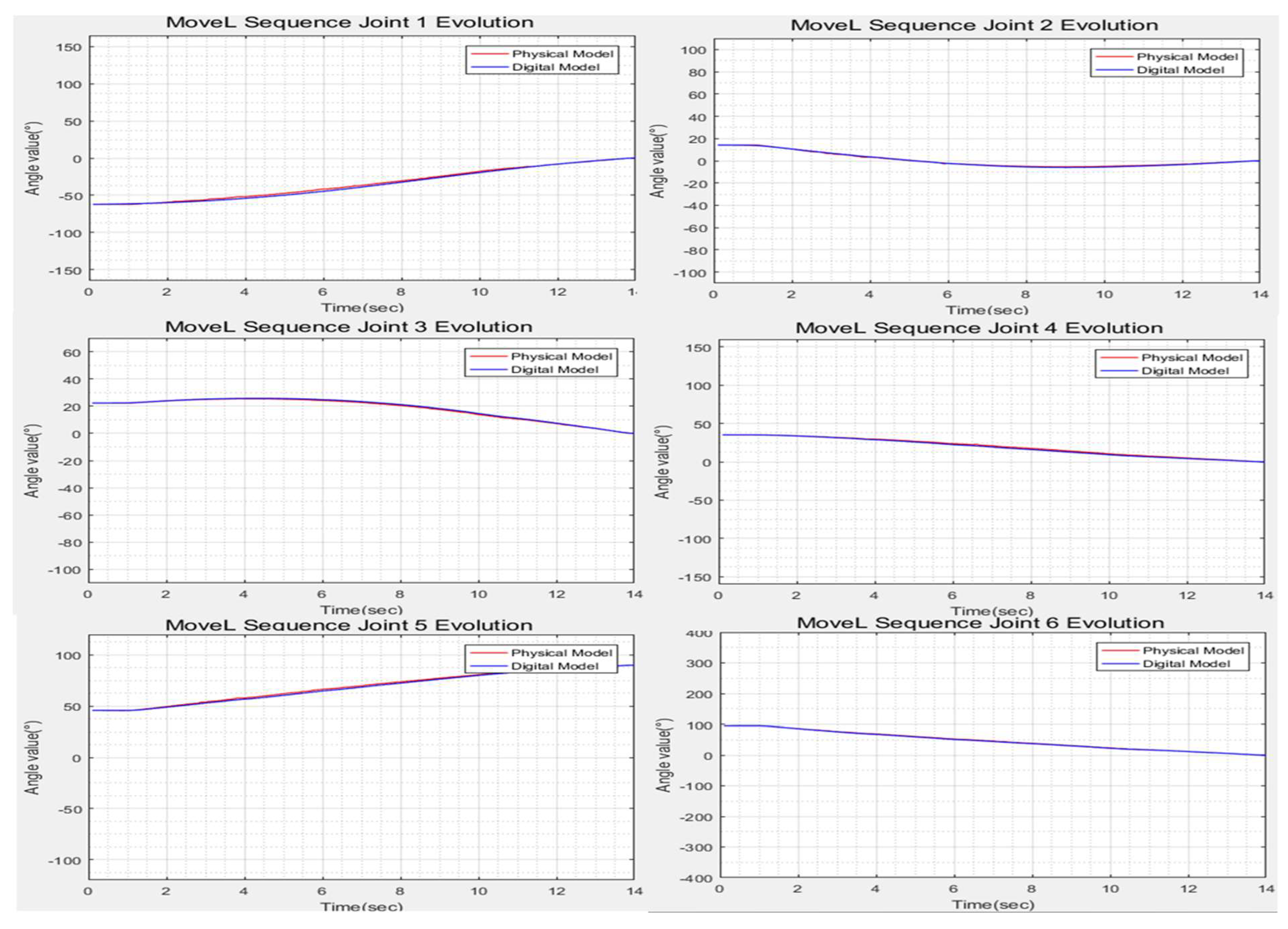
Disclaimer/Publisher’s Note: The statements, opinions and data contained in all publications are solely those of the individual author(s) and contributor(s) and not of MDPI and/or the editor(s). MDPI and/or the editor(s) disclaim responsibility for any injury to people or property resulting from any ideas, methods, instructions or products referred to in the content. |
© 2025 by the authors. Licensee MDPI, Basel, Switzerland. This article is an open access article distributed under the terms and conditions of the Creative Commons Attribution (CC BY) license (http://creativecommons.org/licenses/by/4.0/).
Copyright: This open access article is published under a Creative Commons CC BY 4.0 license, which permit the free download, distribution, and reuse, provided that the author and preprint are cited in any reuse.


