1. Introduction
The paper proposes the design and implementation of remote or local monitoring and control a laboratory mechatronics system based on IoT-Cloud, VPN and DT approach. The mechatronic system is a MRC, equipped with an industrial robotic manipulator, ABB 120 IRM, which performs the flexible assembly of two workpieces, each consisting of five components. The system can also, perform disassembly, and replacement allowing the parts to be recovered, possibly for reuse or resale. If the assembled workpiece is totally compromised, it is returned to the MRC on the conveyor belt for complete disassembly or replacement parts, [
1,
2,
3,
4,
5,
6]. The ABB 120 IRM integrated into MRC performs intricate A/D/R tasks using data from IoT sensors that monitor component positioning, alignment, and force applied during joining. The system adapts in real-time to any variances, using data-driven insights from cloud-based AI (ML) models. Through the equipment used as edge IoT devices and the software packages involved, the whole system wants to respond to the Industry/Education 4.0 and 5.0. Edge IoT devices, such as wireless router, PLC, embedded computer, image processor, ABB IRM Controller, communication devices, and servo drivers are connected in a local network, in turn, connected to the Internet, via WAN, [
6,
7]. Also, for IoT integration is necessary to equip the MRC, with IoT sensors and cameras to capture real-time operational data during assembly, disassembly, and part replacement tasks. IoT gateways are used to aggregate sensor data and transmit it securely to the cloud for real-time analysis and control actions. In the future we intend to develop cloud platform to host data, analytics, control applications and use cloud-based applications for visualizing the status of assembly, disassembly, or replacement operations, including task progression, error reporting, and predictive maintenance alerts. All of these, enable remote monitoring, real-time feedback, and decision-making capabilities. The role VPN connection is to provide secure, encrypted communication between MRC and authorized remote user. VPN ensures that data between the MFC, cloud platform, and remote user is protected from cyber threats {
8,
9,
10}.
The DT is a virtual replica of MRC system, including the ABB 120 IRM and its interactions with the A/D/R tasks. It mirrors the real-world processes, allowing real-time monitoring, simulation, and task optimization. The assignment, planning, and execution of tasks, in simulated mode, consisting of logical schemes connected to hardware components, and visual signaling of the current operation performed by the ABB IRM, represents a concept of AR. The modeling of A/D/R operations through STPN, the formalization and simulation of the models, represents the VR counterpart. for the real-time operations of the MRC. AR adds an interactive layer of digital information into the physical world, which can greatly enhance task planning, troubleshooting, and operator assistance during A/D/R tasks. AR can provide step-by-step instructions for A/D/R tasks, enhancing accuracy and speed by guiding user through complex procedures in real-time. Remote user can custom AR to visualize the status of the MRC and provide support to on-site personnel by seeing what they see and guiding them through tasks remotely. VR allows operators to enter a fully immersive virtual environment that simulates the MRC’s tasks and workflows. Coupling VR with STPN models enhances the user experience by providing a formal model for analysing and optimizing tasks. STPN simulation within VR environments can be used to map out and test task flows for the ABB 120 IRM, [
6,
11,
12,
13,
14,
15,
16,
17]. This method ensures that A/D/R tasks follow the most efficient sequence while considering time constraints. User can experience the entire A/D/R process virtually, identifying potential inefficiencies before deploying on the physical MRC. The monitoring signals acquired from the PLC must correspond to those obtained from the virtual world.
A SCADA system is integrated into the system for real-time control and automation. SCADA gathers data from IoT sensors and actuators on the ABB 120 IRM and other devices to provide real-time feedback to the operators. SCADA system allow user to monitor and control the ABB IRM’s movements, the sequencing of A/D/R tasks, and the status of connected devices (e.g., conveyors, pick-and-place systems). SCADA interfaces provide visualizations of the MRC’s status, showing real-time data such as component positions, actuator states, and task progression. User can involve this data to make informed decisions. The SCADA system can trigger automatic actions based on predefined conditions or operator inputs, ensuring MRC operates autonomously within set safety and performance parameters, [
18,
19,
20,
21,
22,
23,
24,
25,
26,
27,
28,
29,
30].
Several HMI are designed, allowing users to interact, remote or local, with the MRC, access key metrics, and manually control when needed. The HMIs provide real-time feedback from SCADA, DT, IoT sensors and detailed information about MRC status, including the workpiece’s A/D/R progress. In the future the HMIs will be enhanced with AI (ML)-powered decision support, offering recommendations for task sequencing, maintenance schedules, or component adjustments based on the current system status, {
3,
6].
OPC-UA is integrated to ensure standardized and secure communication between various devices in the MRC. It enables interoperability between different systems such as the ABB 120 IRM, A/D/R stations, IoT sensors, PLC, embedded computer, cameras, Video Processing Unit (VPU), IoT gateway, conveyor driver and cloud -platform. OPC-UA acts as a bridge between the local control systems (SCADA, HMIs) and the cloud-based infrastructure, facilitating smooth data flow, A/D/R processes coordination and real-time communication. HMI-type SCADA systems are designed, both for initialization and configuration, work remotely and locally for monitoring and control. [
7,
8,
9]. Through a specialized communication device, instantaneous and time horizon electrical data will be acquired from sensors, stored in the embedded computer, or in cloud, useful to develop an adaptive ML for the prevention of breakdowns and maintenance. Thus, the system has a robust operation, at the same time ensuring data protection and inviolability, {
3,
6].
The rest of the paper is organized in 6 sections. Hardware structure of A/D/R MRC for remote or local monitoring and control multilevel architecture based on IoT edge devices, LAN, WAN Networking, Cloud and VPN connections, is presented in
Section 2. In
Section 3, Digital Twin’s virtual world counterpart of A/D/R MRC together with task planning as AR and STPN models, formalism and simulation, as VR, all of these, for assembly, disassembly and cylinder replacement, are presented in
Section 3. IoT-Cloud and VPN remote monitoring and control together with remote or local initialization and selection, via A/D/R HMIs, cloud and embedded computer, based data storage and analytics, Machine Learning for adaptive control, optimization and predictive maintenance are presented in
Section 4. Several remarks about the approach and results and how they fit into the context of AI (ML), Industry and Education 4.0 and 50, can be found in
Section 5, Discussion. Final remarks, paper contributions and future research are stated in
Section 6, Conclusions.
2. Hardware Structure of A/D/R MRC
2.1. IoT Edge Devices and LAN/WAN Networking
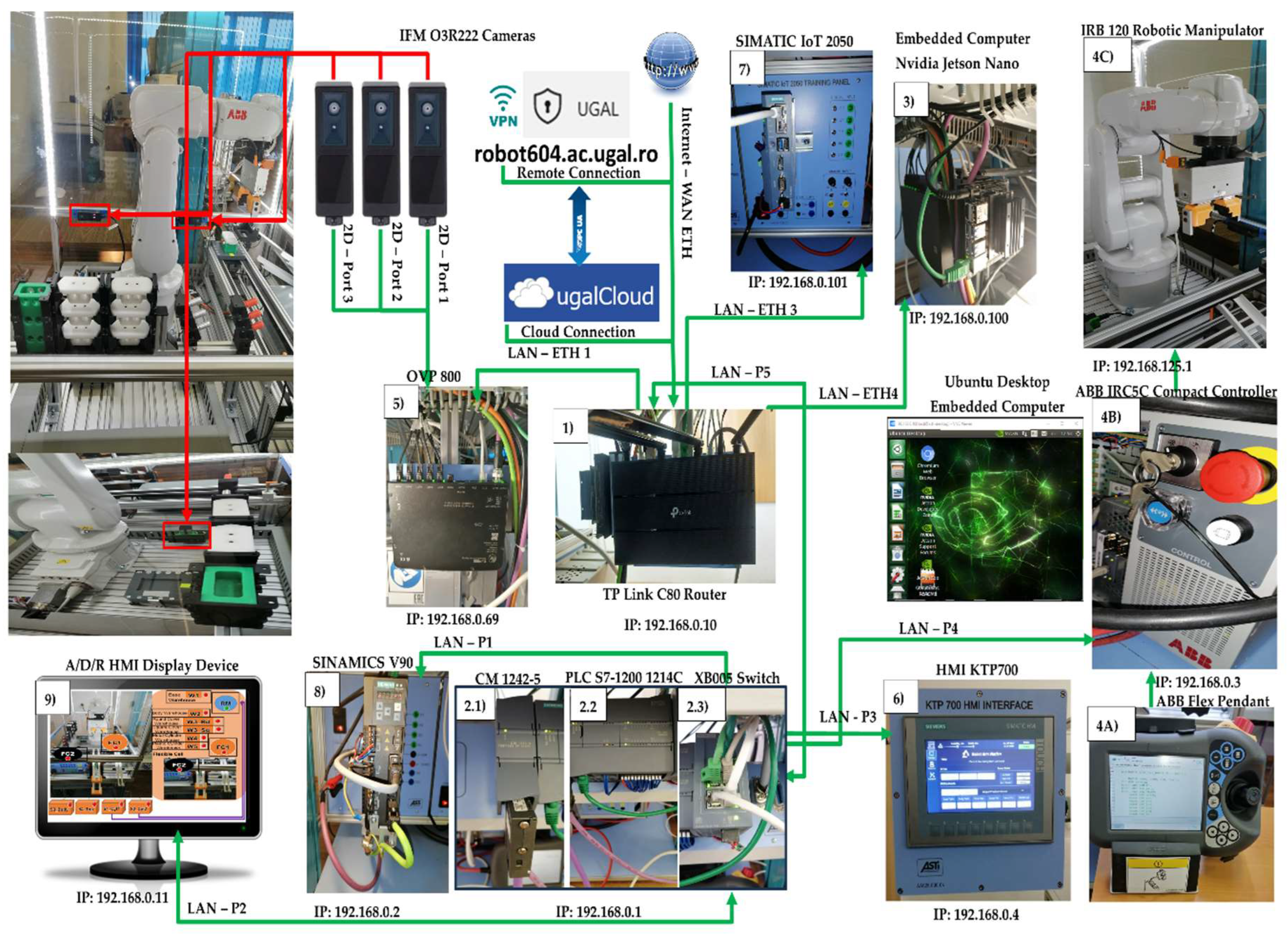
In
Figure 1, it is displayed all the devices connected to the LAN, each device having its own unique IP address.
1). WI-FI router (TP-Link Archer) has the role of WI-FI network management, assures LAN, ETH, and WAN connectivity to the Cloud via Internet.
2.2). SIEMENS PLC 1214C DC/DC/DC as HMI’s main control unit, allows all other devices to communicate with it, manages all signals (on sensors or from communication) and internal variables which are using by remote and local SCADA system. Remote and local SCADA systems are using PLC’s internal variables, send/receive data to/from IFM devices (3D cameras that provide images and information about the number of parts in the storage warehouses before and after a handling operation) and is programmed in TIA V17.
3). Embedded computer NVIDIA Jetson Nano has a Virtual Network Computing (VNC) server running on it, and VNC Viewer is enabled for remote connection. Jetson Nano has access to all the other devices, web browser for Node-RED interface, has installed docker environment, and docker images. Jetson Nano embedded computer can run the same docker image as the OVP800 for cameras management, allows Node-RED programming and testing, and docker development.
4A). ABB touch pendant,
4B). ABB IRC5C controller, and
4C). 6-DOF ABB 120 IRM together IO-Interface: 192.168.0.3 (PLC signals), and service 192.168.125.1 (Robot Studio Communication) execute the actions configured by user on remote and local HMI SCADA dashboards, send/receive data to/from PLC and is programmed in Robot Studio.
5). Video Processing Unit (VPU), OVP 800, assures artificial vision management, send/receive data to/from PLC, controls the 3 cameras via ROS2 Humbles using IFM3D_ROS2 library. OVP 800 runs ROS2 Humbles for cameras management, parts detection algorithm, PLC communication, WebSocket server (for Node-RED communication).
6). Local SCADA system HMI KTP 700 allows the operator to local control FRC and send/receive data to/from PLC.
7). SIEMENS IOT2050 is used as remote SCADA System, send/receive data to/from PLC, video streams from IFM cameras, stores energy records, and can replicate the HMI KTP 700 interfaces.
8). SIEMENS S INAMICS V90 is the conveyor control unit, send/receive data to/from PLC and is programmed in TIA V17.
9). Local HMI display device.
2.3). Communication adapter XB005 Switch, attached to S7-1214 PLC is used for connecting, via LAN, to digital ports the following devices: to P1, SINAMICS V90; to P3, secondary SCADA system, HMI-KTP 700; to P4, ABB controller; to P5, WI-FI router and to P2, A/D/R local HMI display device
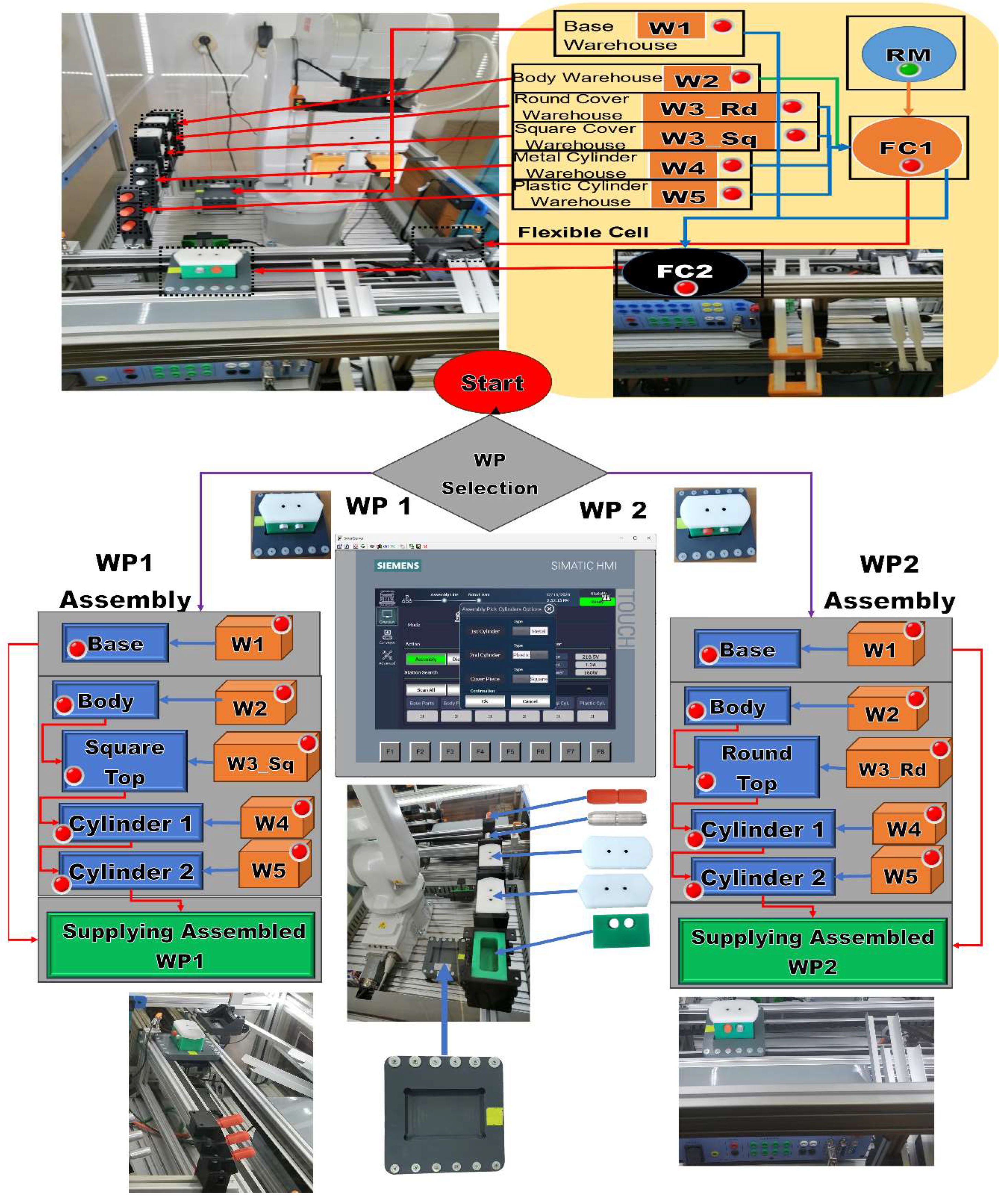
2.1). Communications module SIMATIC CM 1242-5, attached to S7-1214 PLC, is used for connection of the SIMATIC S7-1214 PLC to PROFIBUS (DP slave module). MRC has 6 warehouses for storing three components each: Base (Pallet) warehouse (W1); Body warehouse (W2); Round Cover (Top_Rd) warehouse (W3_Rd), Square Cover (Top_Sq) warehouse (W3_Sq); Metal cylinder warehouse (W4); Plastic cylinder warehouse (W5). Three IFM O3R222 cameras, for detecting the number of parts in the warehouse: cameras: the Base detection camera is connected to port 1 of the VPU-OVP800; the Body and Top detection camera is connected to port 2 of the VPU-OVP800; the camera for the detection of Metal and Plastic cylinders is connected to port 3 of the VPU-OVP800.
The MRC is equipped with a conveyor belt, for transporting the workpiece to the left and right entrances/exits. At the two inputs and outputs there are inductive sensors that signal the presence of the workpiece according to the metal markers on the Base (Pallet) as can be seen in
Figure 3. Thus, the MRC can be interconnected with other mechatronics stations that operate A/D/R on the same types of workpieces and parts (e.g. 6-workstation A/D/R Mechatronics line, Hera&Horstman, [
6]).
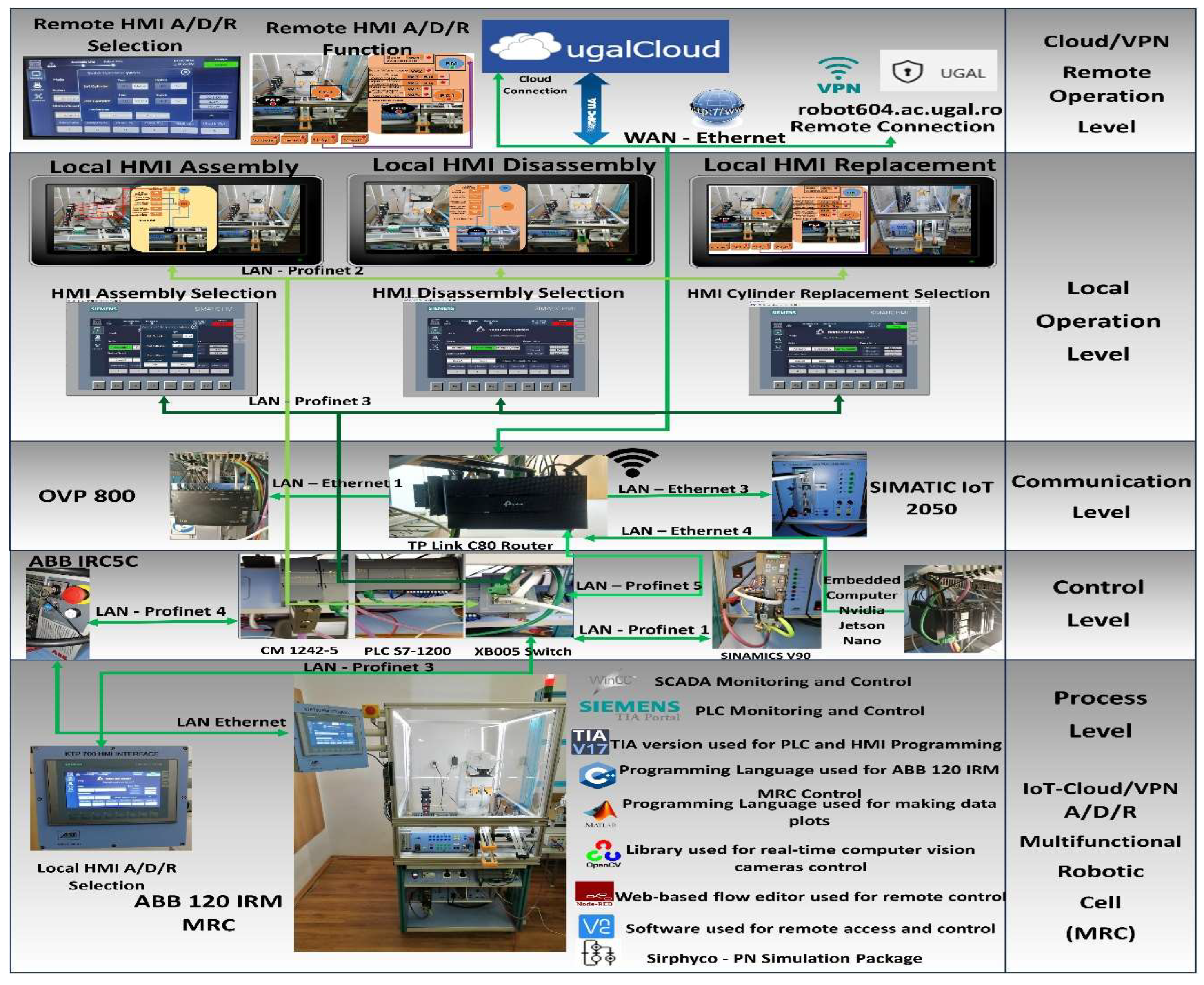
2.2. Cloud and VPN-Based Monitoring and Control Multilevel Architecture
The flexible A/D/R operations performed by MRC consist of assembly of two workpieces (WP1, WP2), disassembly and replacement of cylinders with recovery of parts for reuse, [
2],[
3],[
6]. The control structure, shown in
Figure 2, is multilevel as follows
: 1). Remote operation level, with SCADA, remote HMI A/D/R and remote HMI selection A/D/R for remote monitor and control of assembly, disassembly and replacement.
2). Remote operation level, with SCADA, local HMI A/D/R and local HMI selection A/D/RT for remote monitor and control of assembly, disassembly and replacement.
3). Communication level with video processing unit (VPU) OVP 800, Wi-Fi Router, TP link Archer and SIMATIC IOT2050 as the primary SCADA edge device that connects the various subsystems to the display devices or to the cloud
. 4). Control level with ABB IRC5C controller of ABB 120 IRM, PLC S7-1200 as main control unit together with Switch Ethernet Simatic SCALANCE XB005, SIEMENS CM 1242-5 and SINAMICS V90 for conveyer control and NVIDIA Jetson Nano that is a small, powerful computer for embedded applications that delivers the power for remote SCADA monitoring and control.
5). Process level with ABB 120 IRM with electric gripper that ensures handling of parts inside the cell and HMI KTP 700 as local HMI selection of A/D/R MRC. Next to the MRC are listed the software packages used along with their usage.
3. Digital Twin’s Virtual World Counterpart of A/D/R MRC
The virtual world as the counterpart of the digital twin of A/D/R MRC has two components. The first one is the augmented reality associated with the planning of tasks related to each of the functionalities (assembly, disassembly, replacement of cylinders). The second is the virtual reality associated with the handling displacements performed by ABB IRM, [
31,
32,
33,
34,
35].
The task planning is conceived as an AR implemented as a flow of Node-RED, ([
36]), functions that is transposed into an HMI in which the operations performed by ABB IRM and the tasks in the organization chart are executed synchronously (using PLC signals). The execution of a task corresponds to a monitoring signal which in the organizational chart is signaled by lighting the spotlight.
To model and simulate the virtual reality of each MRC functionality, use the Synchronized Timed Petri Nets tool. Starting from the linear and angular displacement limitations of ABB IRM from the times required for handling the parts and transporting the workpiece on the conveyor belt, the STPN models related to assembly, disassembly, and replacement of cylinders were released. In the STPN models, the states in red are control states associated with the control functions of the decision actions, being states that trigger a transition when they receive a token. The states in brown or gray correspond to the pick and place actions and the end of the token after the end of the transition. Yellow states correspond to monitoring actions and end token after a handling or transport transition has been completed. There is also a state in green, only for assembling and replacing cylinders, which receives a token when an assembled part is delivered or with replaced cylinders. There are also three states in red, synchronization signals that receive a token when one of the functionalities has been completed, conditioning the start of another. The simulation of a STPN model is done in the Sirphyco package, [
10], [
19], [
20] and [
37].
Figure 2.
Cloud and VPN Based Remote Monitoring and Control Multilevel Architecture.
Figure 2.
Cloud and VPN Based Remote Monitoring and Control Multilevel Architecture.
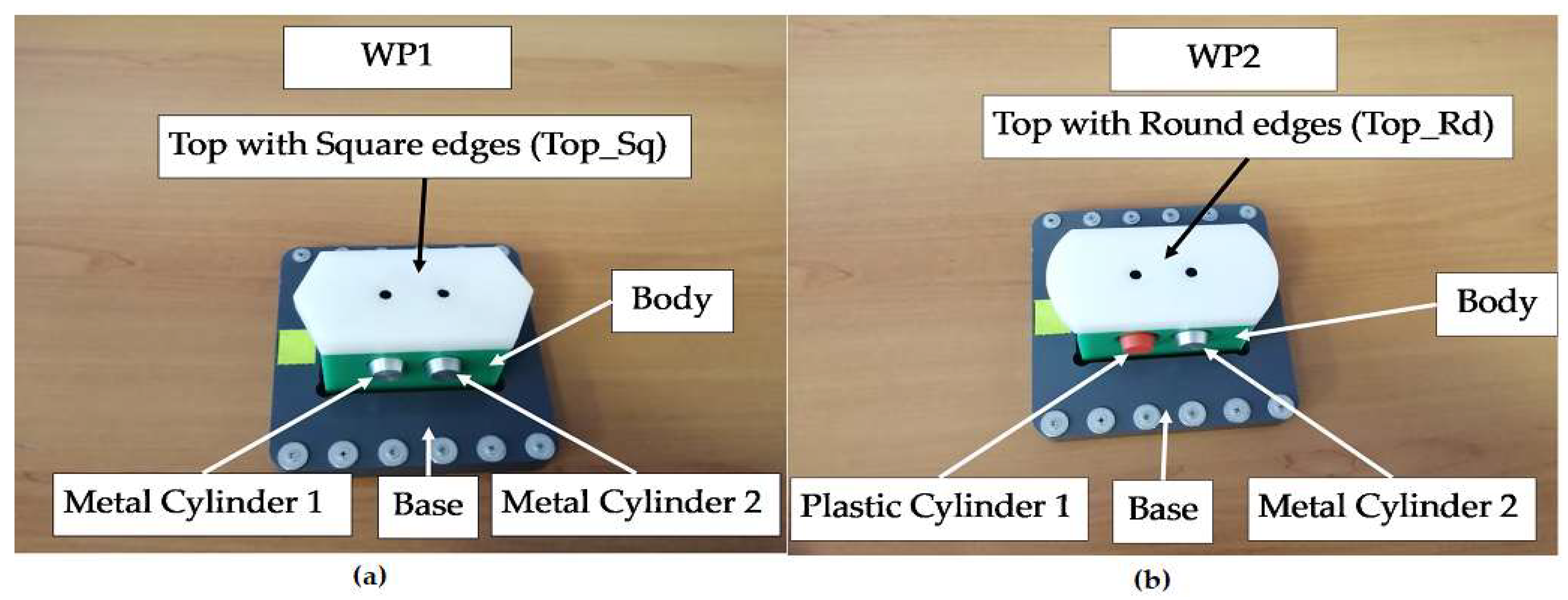
MRC performs each functionality, assembly, disassembly or replacement of cylinders, for two workpieces, called WP1 or WP2, the difference between them is shown in
Figure 3.
Figure 3.
(a)&(b) The parts of the workpieces, WP1&WP2. (a) WP1 with Top_Sq; (b) WP2 with Top_Rd.
Figure 3.
(a)&(b) The parts of the workpieces, WP1&WP2. (a) WP1 with Top_Sq; (b) WP2 with Top_Rd.
3.1. Planning Tasks for Assembly as Augmented Reality
After the assembly is completed, the assembled workpiece is delivered on the conveyor belt at the right exit of the MRC, a location that is also used for the workpiece arrived for disassembly or cylinder replacement. The parts to be assembled are: 1) Base (Pallet), 2) Body, 3) Top with square edges (WP1) or Top with rounded edges (WP2), 4) the left hole of the Body as first cylinder (Cyl1) and 5) the right hole of the Body as second cylinder (Cyl2), both of them Metal or Plastic Cylinder. First, the Base is positioned on the conveyor belt, called FC2, then the rest of the product is assembled in a separate location in MRC, called FC1. After, it is moved by the ABB IRM onto the Base, on FC2. Finally, WP1or WP2 is transferred, along conveyor belt, to the left side exit of the MRC. In
Figure 4, are marked the locations, FC1 and FC2, where the partial (Body, Top_sq or Top_rd, Cyl1 and Cyl2) and total assemblies are made by transferring and placing with ABB IRM the workpiece from FC1 to FC2 on the Base. Assembly task planning is conceived as AR implemented as a flow of Node-RED functions that is transposed to the remote or local HMI where the assembly operations, performed by ABB IRM, run synchronously between the MRC and the task flowchart, as is shown in
Figure 4.
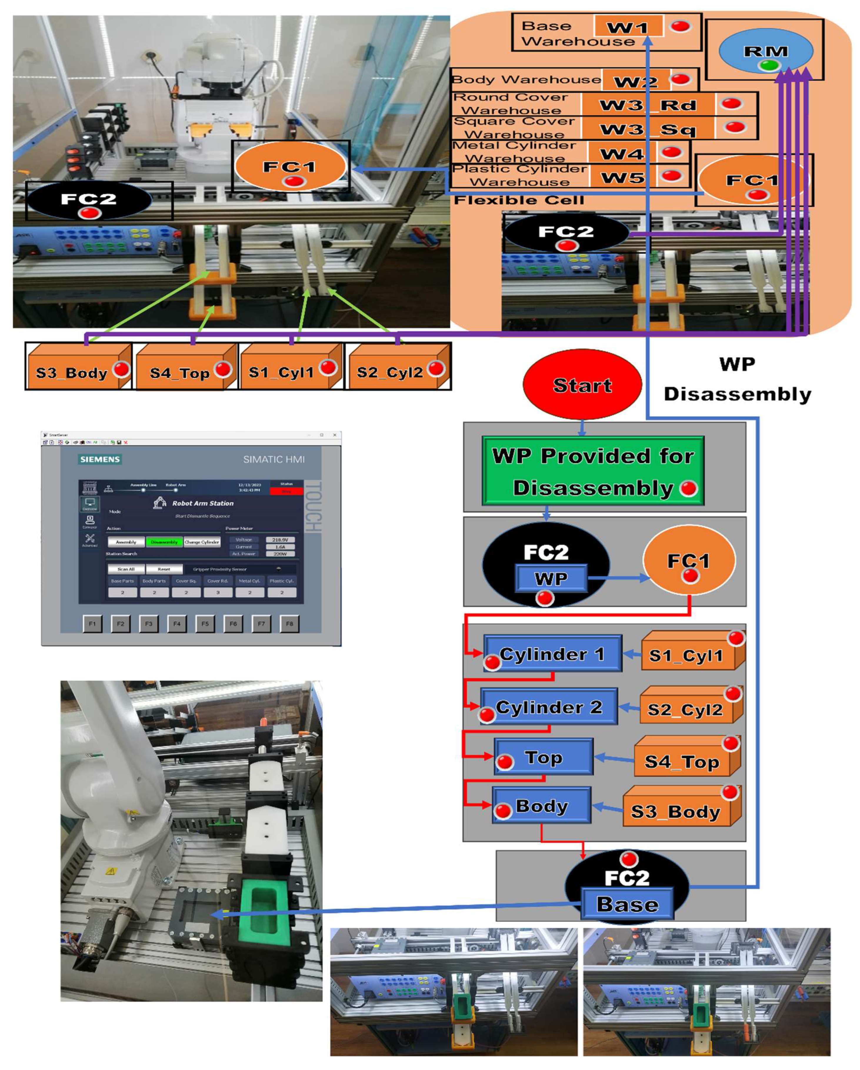
3.2. Planning Tasks for Disassembly as Augmented Reality
WP1 or WP2 are available for disassembly on the conveyor belt at the right entrance of the MRC. It is transported by conveyor to the FC2 location. ABB IRM takes the partially assembled workpiece and places it in the location of FC1. Here, the disassembly is done by ABB IRM by means of the gripper accessories, in order Cyl1, and Cyl2 pushed by sliding on the inclined chutes S1_Cyl1 and S2_Cyl2. Then, grab and manipulate the Top by sliding it onto S4_Top. In the same way, he grabs and manipulates Body, leaving it by sliding on S3_Top. The last operation performed by ABB IRM is taking the Base from FC2 and placing it in warehouse W1, Similar to assembly, task planning for disassembly, is conceived as augmented reality implemented as a flow of Node-RED functions that is transposed to the remote or local HMI where the disassembly operations, performed by ABB IRM, run synchronously between the MRC and the task flowchart as is shown in
Figure 5.
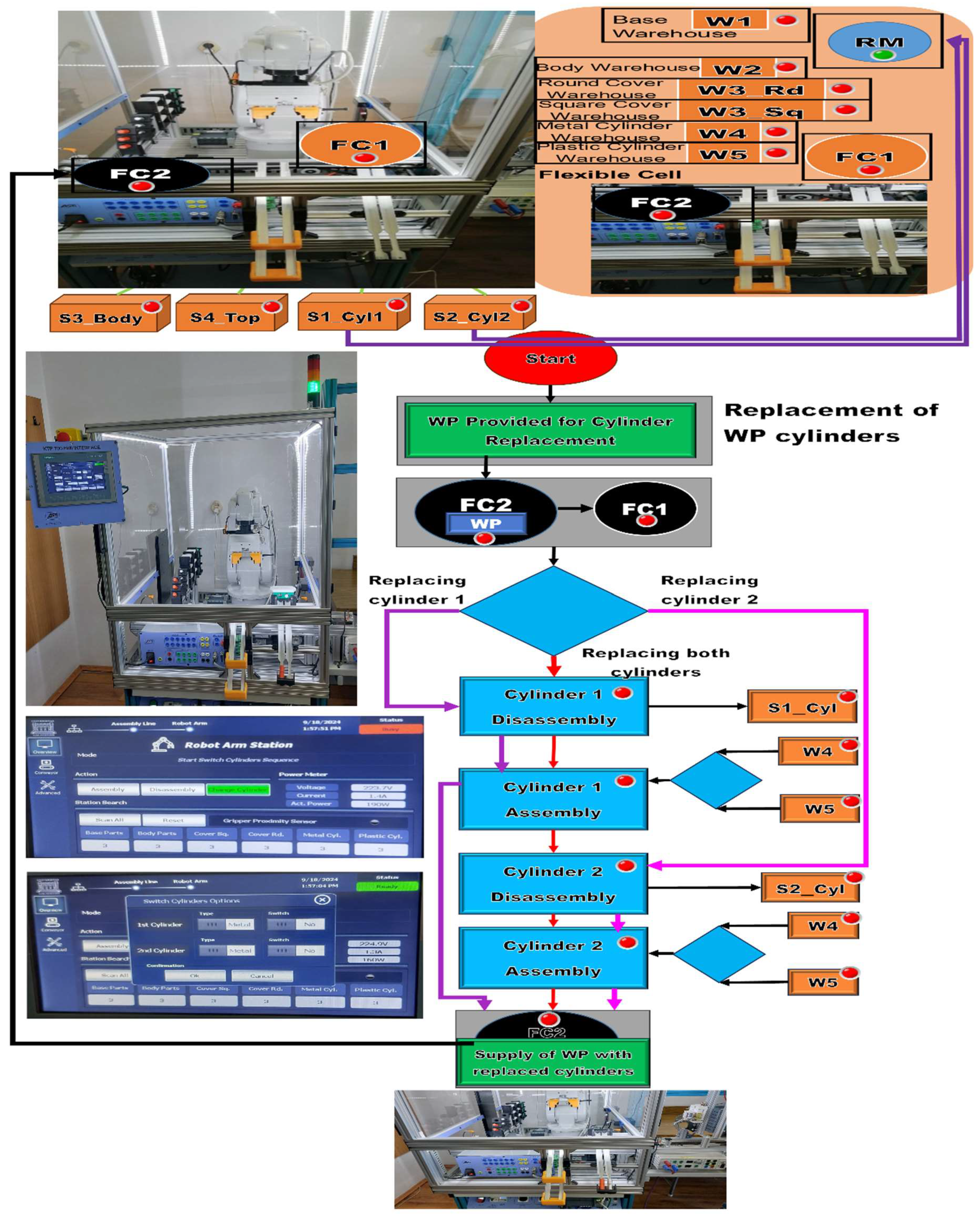
3.3. Planning Tasks for Replacing Cylinders as Augmented Reality
WP1 or WP2 are available for replacement of cylinders on the conveyor belt at the right entrance of the MRC. It is transported by conveyor to the FC2 location. ABB IRM takes the partially assembled work piece and places it in the location of FC1. The sequence of operations when changing the cylinders is as follows. If in the remote or local HMI selection, the change of a single cylinder (cylinder 1 or 2) has been selected, then the corresponding cylinder is disassembled and pushed onto the inclined chute S1_Cyl1 or S2_Cyl2. Then, ABB IRM takes the Metal or Plastic cylinder from W4 or W5 (corresponding to the HMI option) and assembles it in the corresponding hole. If it was decided to change both cylinders, then the operations of changing a single cylinder are repeated in the order cylinder 1 then cylinder 2. After it is moved by the ABB IRM onto the Base, on FC2. Finally, WP1or WP2, with cylinder replaced, is transferred along conveyor, belt to the right-side exit of the MRC. Like assembly and disassembly, task planning for the cylinder replacement is conceived as AR implemented as a flow of Node-RED functions that is transposed to the remote or local HMI where the replacement operations, performed by ABB IRM, run synchronously between the MRC and the organization chart tasks, as shown in
Figure 6.
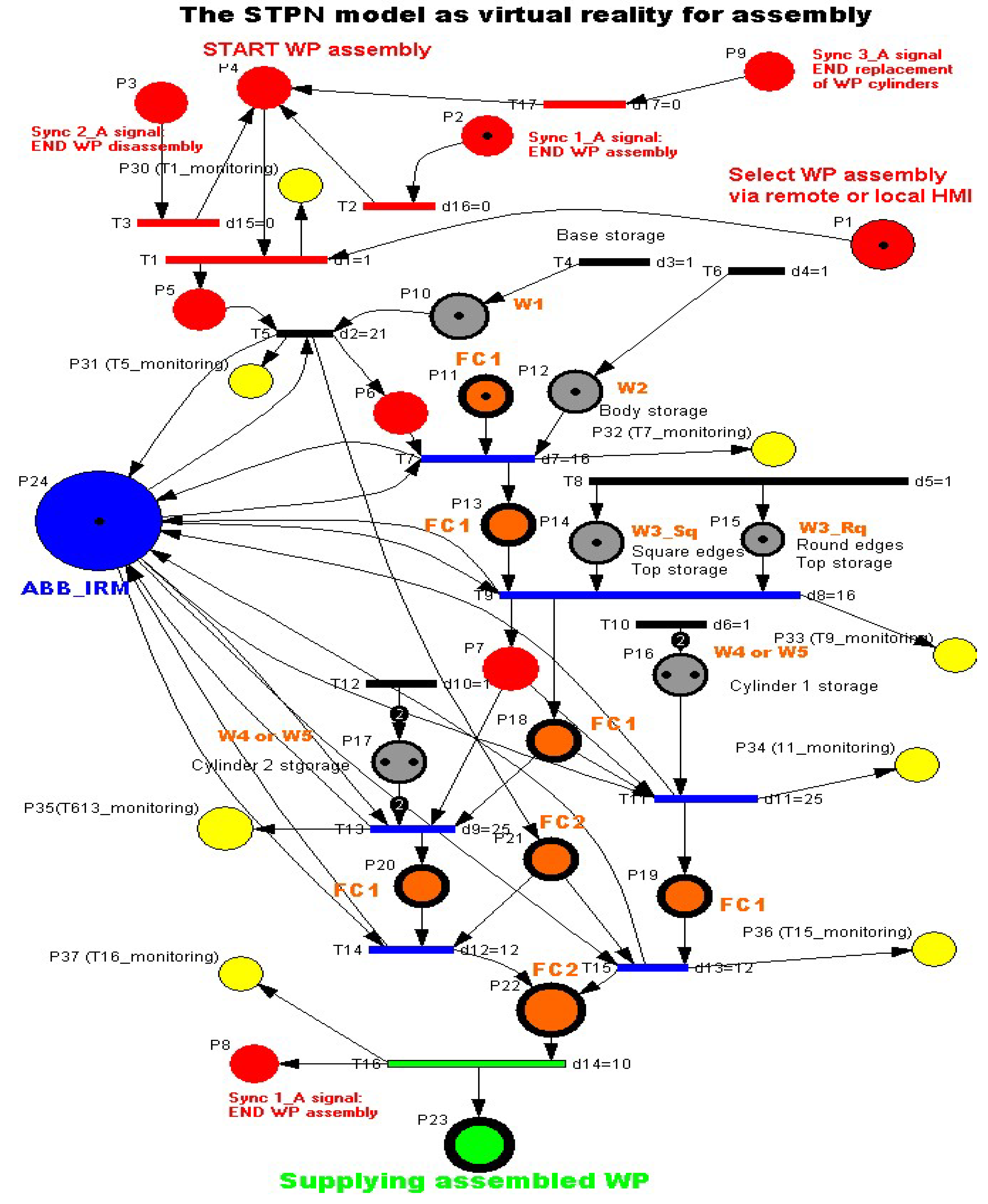
3.4. STPN Model, Formalism and Simulation for Assembly as Virtual Reality
Following the task planning, the STPN model was developed for the assembly of WP1 or WP2, that involves taking parts from the warehouses, handling and assembling them in FC1, respectively FC2, transporting the assembled workpiece on the conveyor to the right exit of the FRC, all this with the corresponding time durations. Three synchronizing signals from the sensors are required to signal that the previous assembly, disassembly or cylinder replacement has ended, [
3,
4,
5,
6,
7,
8,
9]. The STPN model is shown in
Figure 7.
The STPN model is defined by:
where:
The elements of the from (2) are:
is the places set partitioned in:
where:
represents the state set associated to control functions of the decision actions,
represents the set of the discrete places modeling the flexible assembly operations for the two work pieces, WP1 and WP2,
represents the set of the states the to monitoring of the successive assembly actions for WP1 or WP2.
is the transitions set partitioned in:
where:
is the set of the discrete transitions for the two workpiece (WP1, WP2) assembly,
is the transition associated with the conveyor transport of the assembled workpiece at the right exit of the MRC.
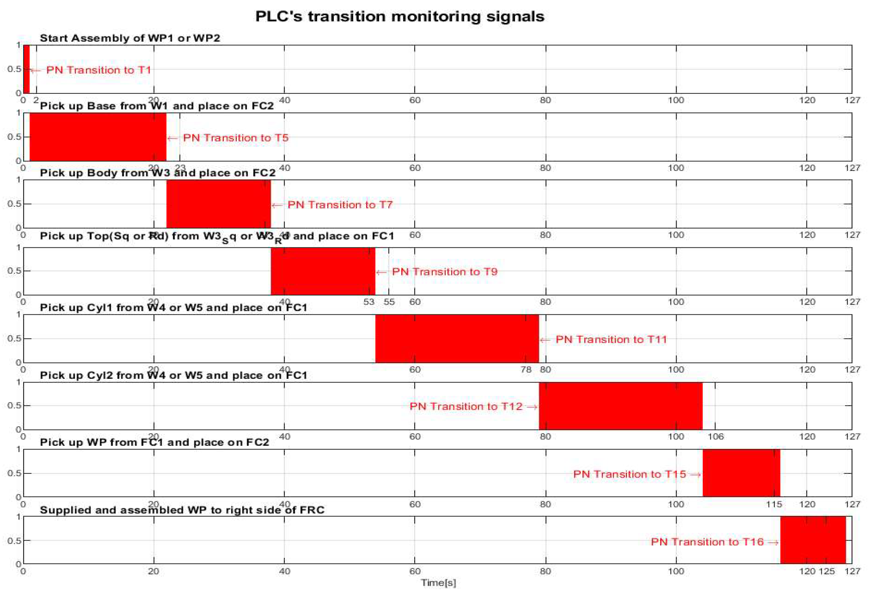
For WP1or WP2 assembly on MRC with ABB 120 IRM, the monitoring places in the set (6) monitor the transitions in the set (8) as follows: P30(T1_monitoring), P31(T5_monitoring), P32(T7_monitoring), P33(T9_monitoring), P34(T11_monitoring), P35(T13_monitoring), P36(T15_monitoring), P37(T17_ monitoring).
is the input incidence function.
is the output incidence function.
is the initial marking of the STPN corresponding to the initial state of the modeled process.
is a function that defines the timings associated to the transitions.
is the set of external events.
The Sync application in definition (1) is a function from the set of discrete assembly transitions to the set of external events joined with the neutral element
e,
Ed1 = Sync1_A signal is synchronization signal for: END WP assembly of the WP1 or WP2.
Ed2 = Sync2_A signal is synchronization signal for: END WP disassembly of the WP1 or WP2.
Ed3 = Sync3_A signal is synchronization signal for: END replacement of WP cylinders of the WP1 or WP2.
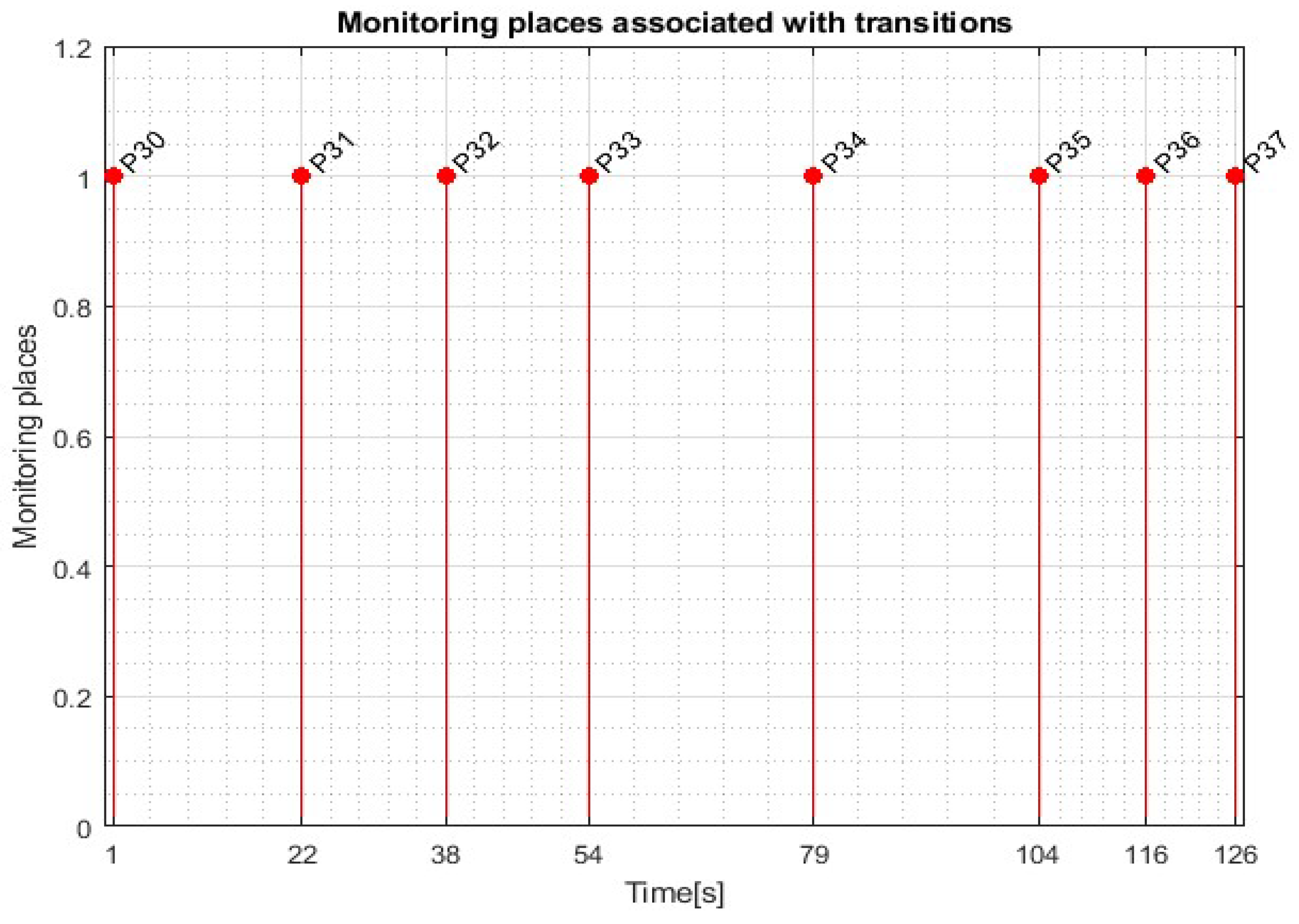
Transitions monitoring states obtained by STPN model simulation in Sirphyco, for the assembly processes of the WP1 or WP2 are presented in
Figure 8, [
38].
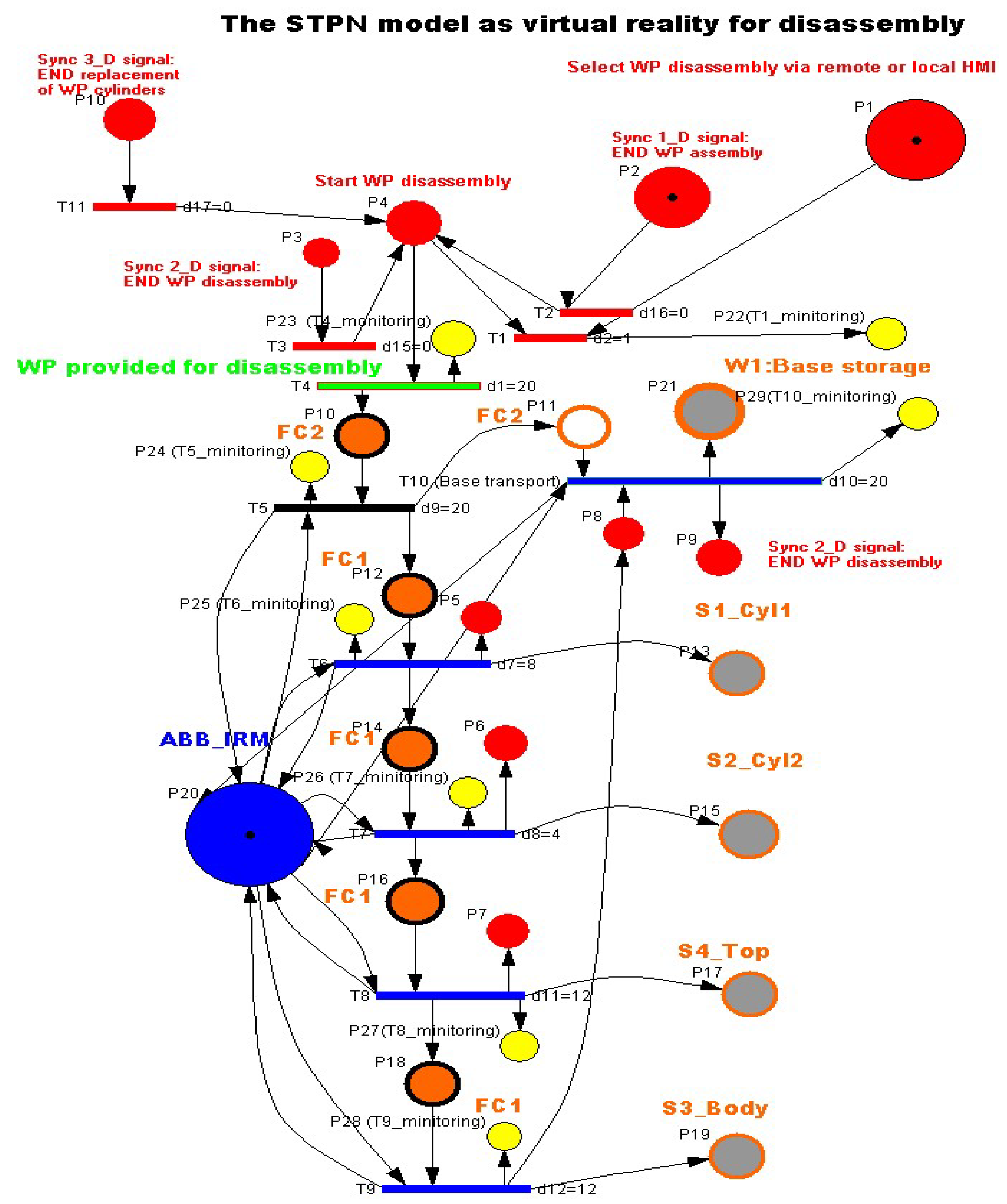
3.5. STPN Model, Formalism and Simulation for Disassembly as Virtual Reality
WP1 or WP2 are available for disassembly on the conveyor belt at the right entrance of the MRC. It is transported by conveyor to the FC2 location. ABB IRM takes the partially assembled workpiece (the part above the Pallet) and places it in the location of FC1. Here, the disassembly is done by ABB IRM by means of the gripper accessories. The parts are disassembled by pushing them on the slide chutes. At the end, the pallet is moved from FC2 to W1. The STPN model with the corresponding transition time durations, is presented in
Figure 9, [
5,
6,
7,
8]. The same three synchronization signals coming from the sensors are needed to signal that the previous assembly, disassembly or cylinder replacement has completed.
The STPN model for the disassembly process is a triplet.
where: TPN is the timed Petri net model,
is a set of external events, and Sync is an application from the set of transitions to that of external events.
The elements of the from (16) are:
is the set of places set, partitioned in:
where:
represents the set of states, associated to the control functions of the decision actions,
represents the set of the discrete places modeling the flexible disassembly operations for the two workpieces (WP1 and WP2),
represents the states set associated to the monitoring of the successive disassembly actions for WP1 or WP2.
is the transitions set partitioned in:
where:
is the set of discrete transitions associated to WP delivered for disassembly,
is the set of the discrete transitions for the two workpiece (WP11 or WP2) disassembly.
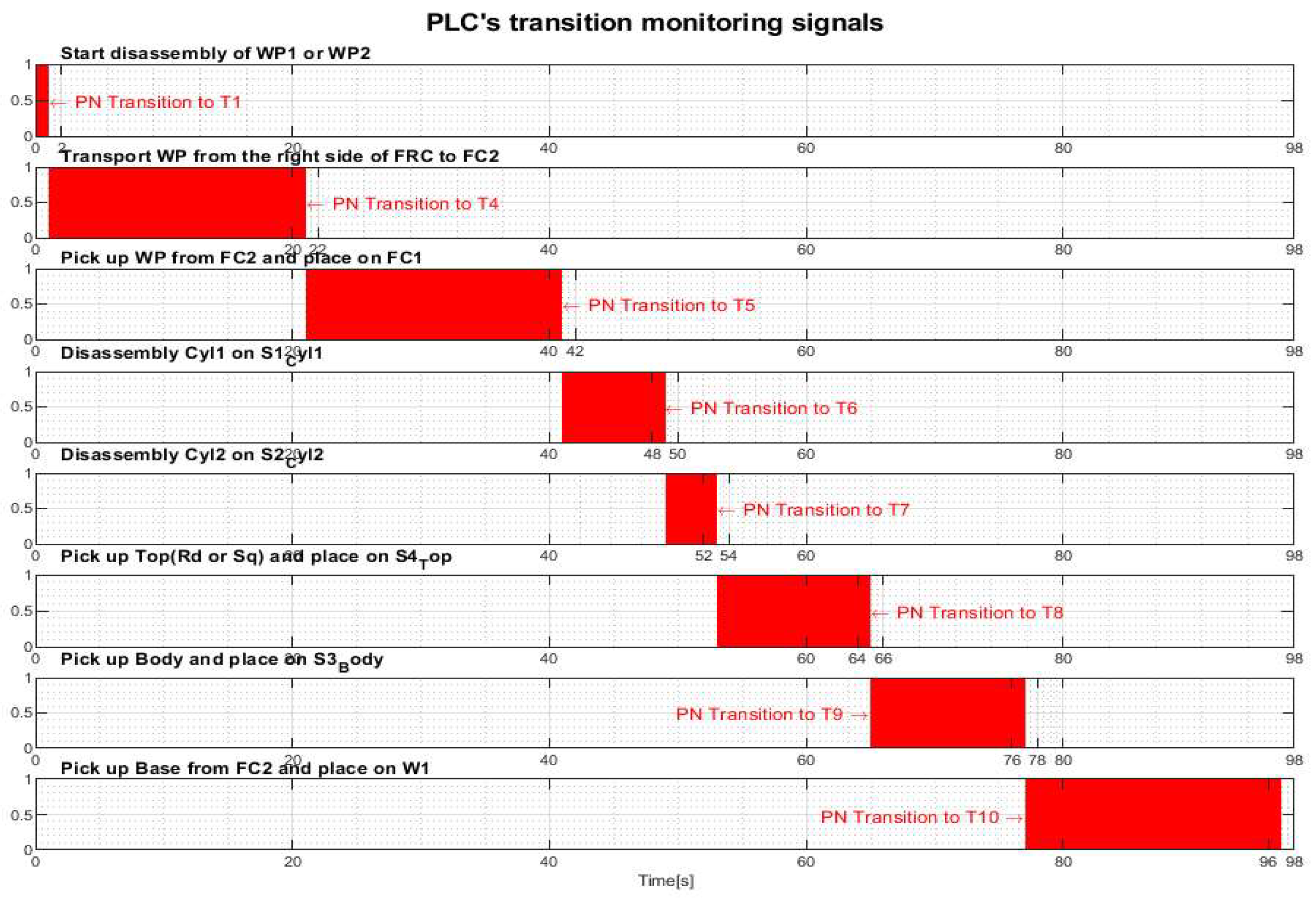
For WP1or WP2 disassembly on MRC with ABB 120 IRM, the monitoring places in the set (20) monitor the transitions in the set (23) as follows: P22(T1), P23(T4), P24(T5), P25(T6), P26(T7), P27(T8), P28(T9), P29(T10).
is the input incidence function.
is the output incidence function.
is the initial marking of the STPN corresponding to the initial state of the modeled process.
is a function that defines the timings associated to the transitions.
is the set of external events.
The Sync application in definition (1) is a function from the set of discrete disassembly transitions to the set of external events joined with the neutral element
e,
Ed1 = Sync1_D signal is synchronization signal for: END WP assembly of the WP1 or WP2.
Ed2 = Sync2_D signal is synchronization signal for: END WP disassembly of the WP1 or WP2.
Ed3 = Sync3_D signal is synchronization signal for: END replacement of WP cylinders of the WP1 or WP2.
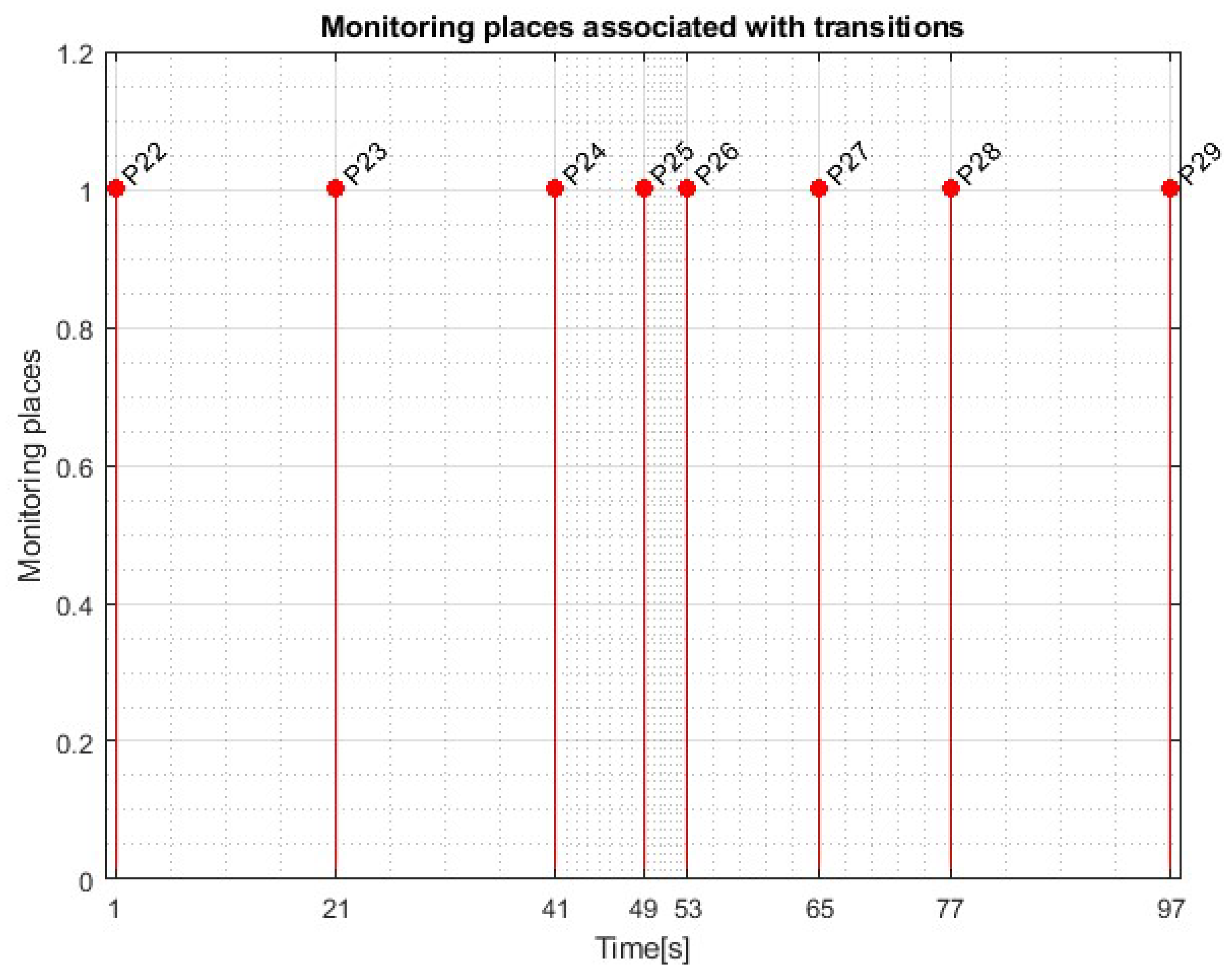
Transitions monitoring states obtained by STPN model simulation in Sirphyco, for the disassembly process of the WP1 or WP2, are presented in
Figure 10.
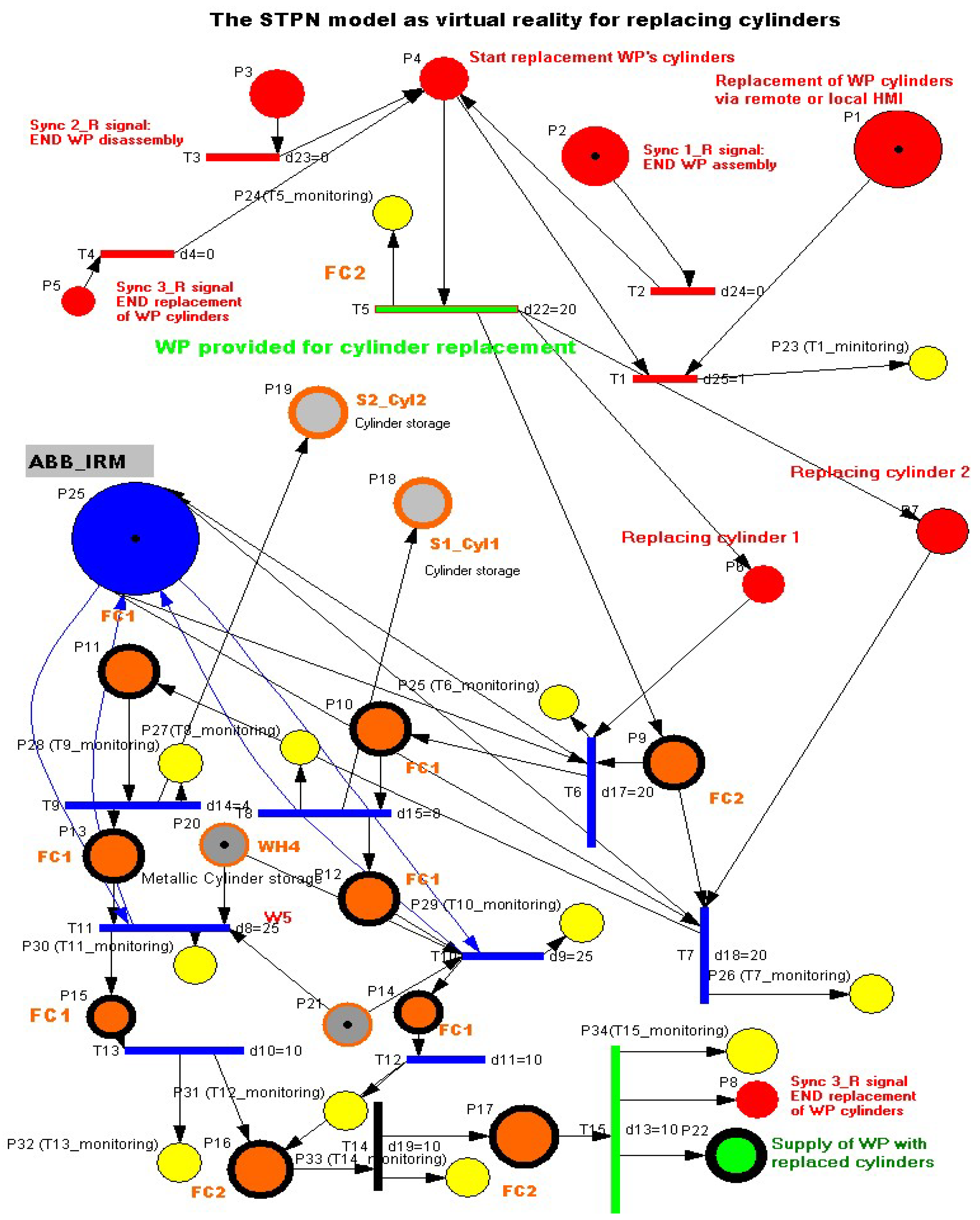
3.6. STPN Model, Formalism and Simulation for Cylinder Replacement as Virtual Reality
WP1 or WP2 are available for replacement of cylinders on the conveyor belt at the right entrance of the MRC. It is transported by conveyor to the FC2 location. ABB IRM takes the partially assembled work piece and places it in the location of FC1. If the change of a single cylinder (cylinder 1 or 2) has been selected, then the corresponding cylinder is disassembled and pushed onto the inclined chute S1_Cyl1 or S2_Cyl2. Then, ABB IRM takes the Metal or Plastic cylinder from W4 or W5 and assembles it in the corresponding hole. If it was decided to change both cylinders, then the operations of changing a single cylinder are repeated in the order cylinder 1 then cylinder 2.
After it is moved by the ABB IRM onto the Base, on FC2. Finally, WP1or WP2, with cylinder replaced, is transferred along conveyor, belt to the right-side exit of the MRC. The STPN model for cylinder replacement together transition time durations are presented in
Figure 11. The same three synchronization signals coming from the sensors are needed to signal that the previous assembly, disassembly or cylinder replacement has completed.
The elements of the from (15) are:
is the set of places, partitioned in:
where:
represents the set of states, associated to the control functions of the decision actions,
represents the set of the discrete places modeling the flexible disassembly operations for the two workpieces (WP1 and WP2),
represents the states set associated to the monitoring of the disassembly actions .
is the transitions set partitioned in:
where:
is the set of discrete transitions associated to WP delivered for disassembly,
is the set of the discrete transitions for cylinder replacement of the two workpiece.
is the transition associated with the conveyor transport to the right exit of the MRC of the workpiece with cylinder replaced.
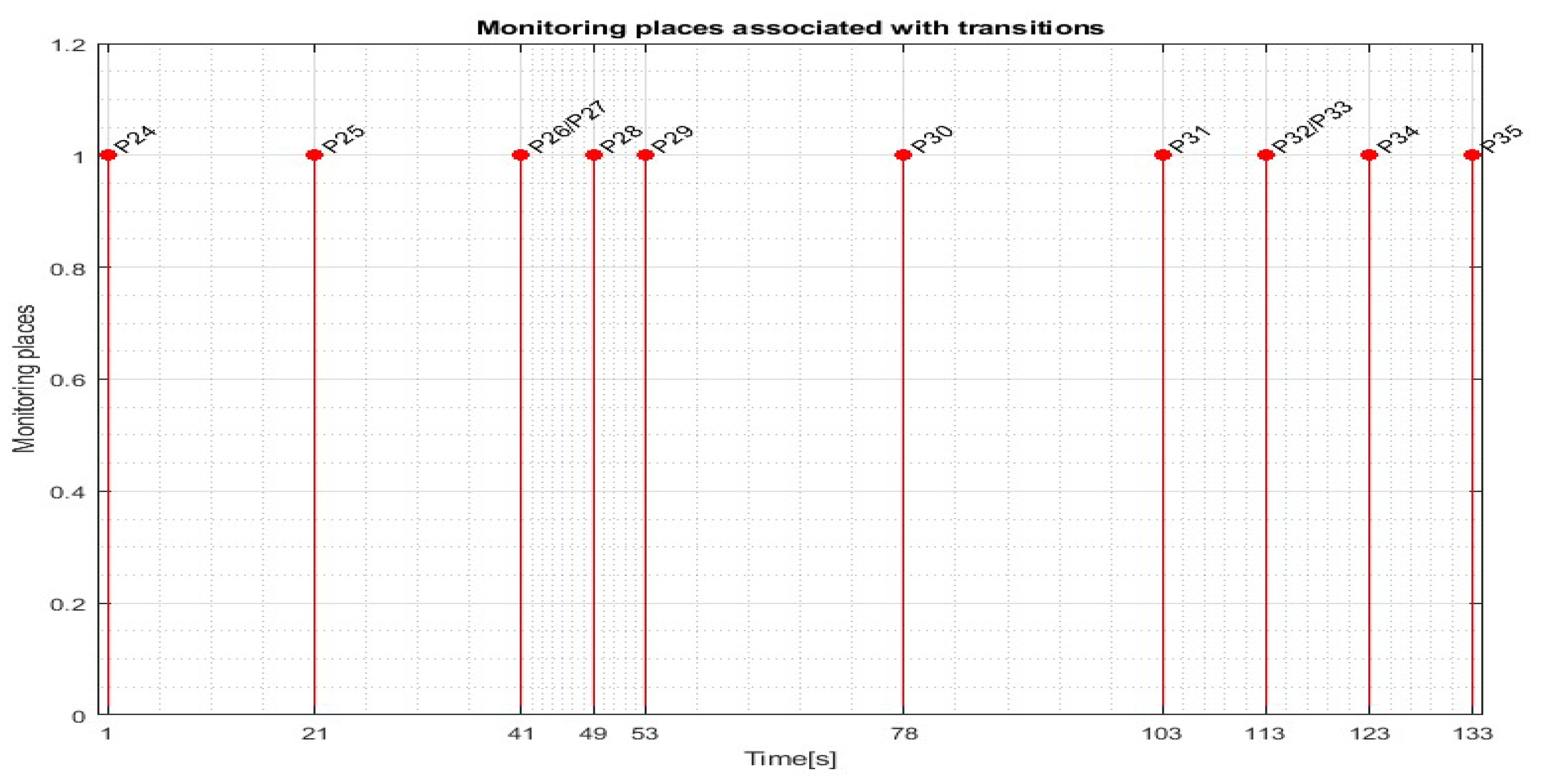
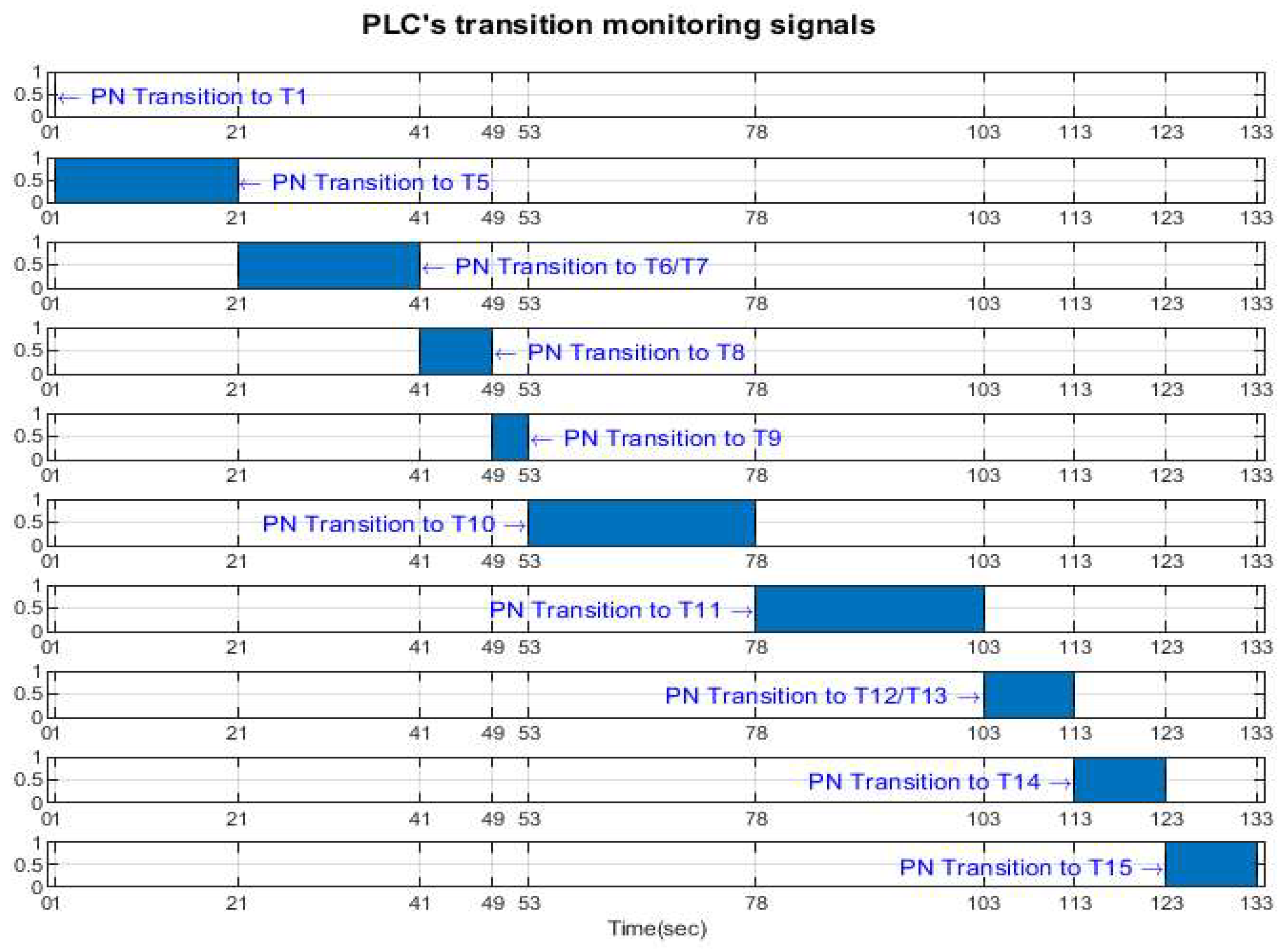
For replacing the cylinders of WP1 or WP2, on MRC with ABB 120 IRM, the monitoring places in the set (34) monitor the transitions in the set (37) as follows: P24(T1_monitoring), P25(T5_monitoring), P26(T6_monitoring), P267T7_monitoring), P28(T8_monitoring), P29(T9_monitoring), P30(T10_monitoring), P31(T11_monitoring), P32(T12_monitoring), P33(T13_monitoring), P34(T14_monitoring), P35(T15_ monitoring).
is the input incidence function.
is the output incidence function.
is the initial marking of the STPN corresponding to the initial state of the modeled process.
is a function that defines the timings associated to the transitions.
is the set of external events.
The Sync application in definition (1) is a function from the set of discrete disassembly transitions to the set of external events joined with the neutral element
e,
Ed1 = Sync1_R signal is synchronization signal for: END WP assembly of the WP1 or WP2.
Ed2 = Sync2_R signal is synchronization signal for: END WP disassembly of the WP1 or WP2.
Ed3 = Sync3_R signal is synchronization signal for: END replacement of WP cylinders of WP1 or WP2.
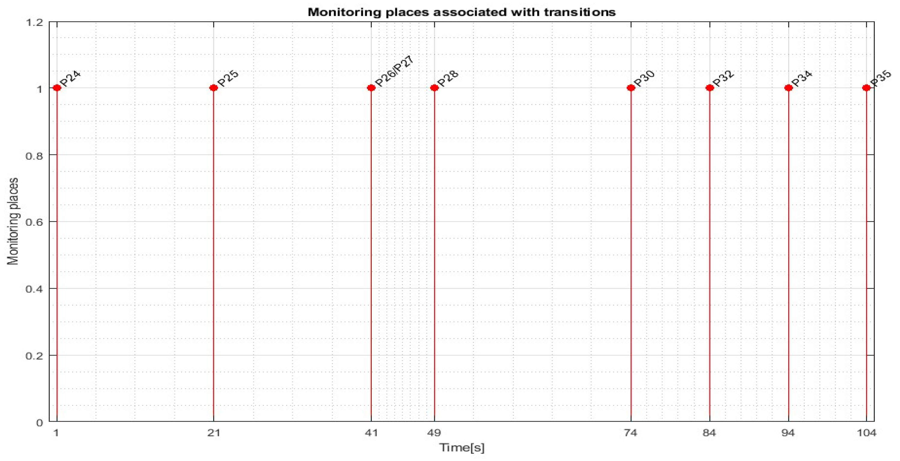
Transitions monitoring states obtained by STPN model simulation in Sirphyco, for the cylinder replacement of the WP1 or WP2 are presented in
Figure 12, for replacement of one cylinder, and in
Figure 13, for replacement of both cylinders.
4. IoT-Cloud and VPN Remote Monitoring and Control
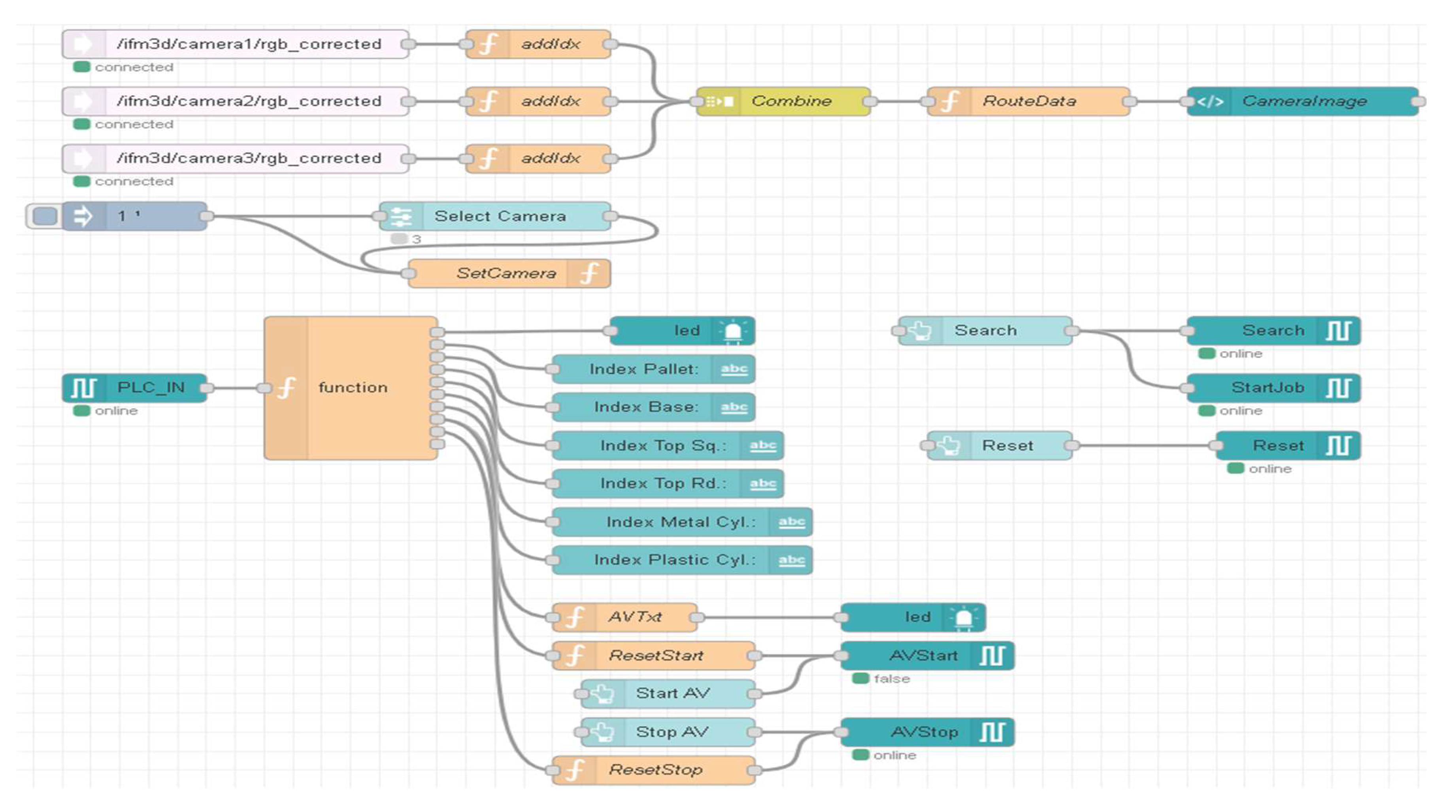
4.1. Remote or Local Initialization and Selection via A/D/R HMIs
Using remote or local HMI, SCADA system, OPC-UA, interactive task planning and the STPN models as the virtual counterpart of digital twin, an application for remote or local monitoring and control of three flexible A/D/R technologies on the MRC, was implemented. MRC is designed in a multilevel and decentralized architecture, with the devices connected into LAN, and Internet, into WAN. The software packages used, make the structure and functionality of the entire system be considered as cyber physical system. At both HMIs, remote or local, there are initialization, selection and start screens, designed in TIA portal, V17, [
39]. Through the scanning process with the 3D and VPU cameras, it is possible to select the type of workpiece, WP1 or WP2, to be assembled or the material of the cylinders, metal or plastic, to be replaced. After each assembly operation, the number of components in each storage warehouse is updated. After each completion of functionality, assembly, disassembly and replacement of cylinders, the warehouses are updated. The workpiece, assembled or with replaced cylinders, is delivered on the conveyor belt to the right exit of the MRC, corresponding to the front view. The workpieces for disassembly or cylinder replacement enters on the conveyor belt from the right side of MRC (the right side of the front view of the MRC,
Figure 2).
4.2. Remote or Local Initialization and Selection via A/D/R HMIs
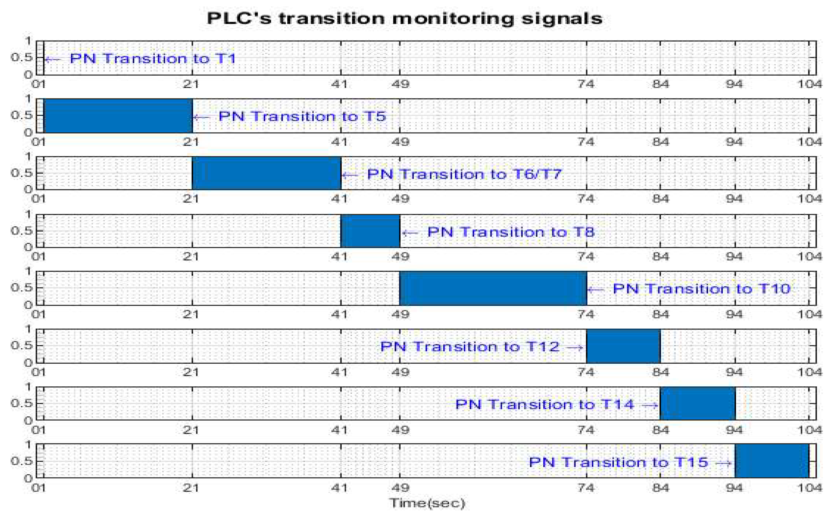
The monitoring signals of the successive actions, acquired, in real-time from the PLC, are represented in
Figure 14, for assembly, in
Figure 15, for disassembly, in
Figure 16, for the replacement of a single cylinder and in
Figure 17 for the replacement of both cylinders. For comparison with the data obtained by simulation in Sirphyco,
Figure 10, for assembly,
Figure 11, for disassembly,
Figure 12, for the replacement of a single cylinder and
Figure 13, for the replacement of both cylinders, the signals acquired in real time approximate well those in the simulation,[
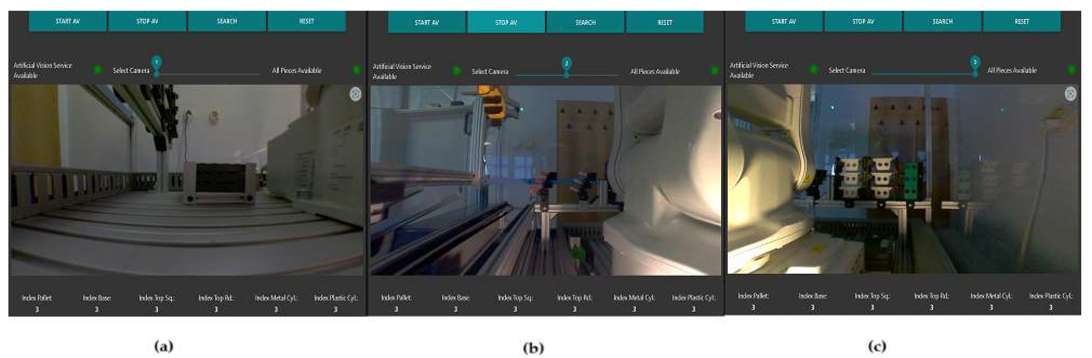
39]. Thus, the virtual digital counterpart of the DT for A/D/R MRC is validated in real time. Using the Node-RED functions, and VNC Viewer, the A/D operations are monitored on the remote SCADA system, in real time. Using Node-RED functions, the flow in
Figure 18 was elaborated to visualize the warehouses with components as can be seen in
Figure 19. The processing of these images in the OVP800 device allows updating the number of components in each warehouse after performing a component manipulation by ABB IRM.
4.3. Cloud and Embedded Computer Based Data Storage and Analytics
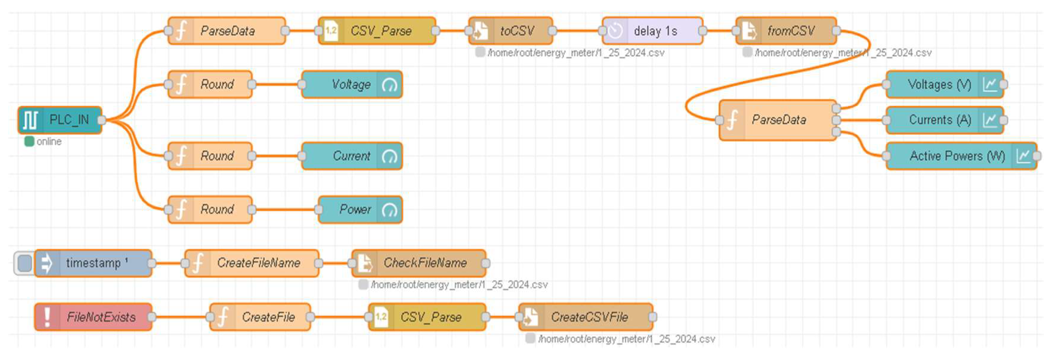
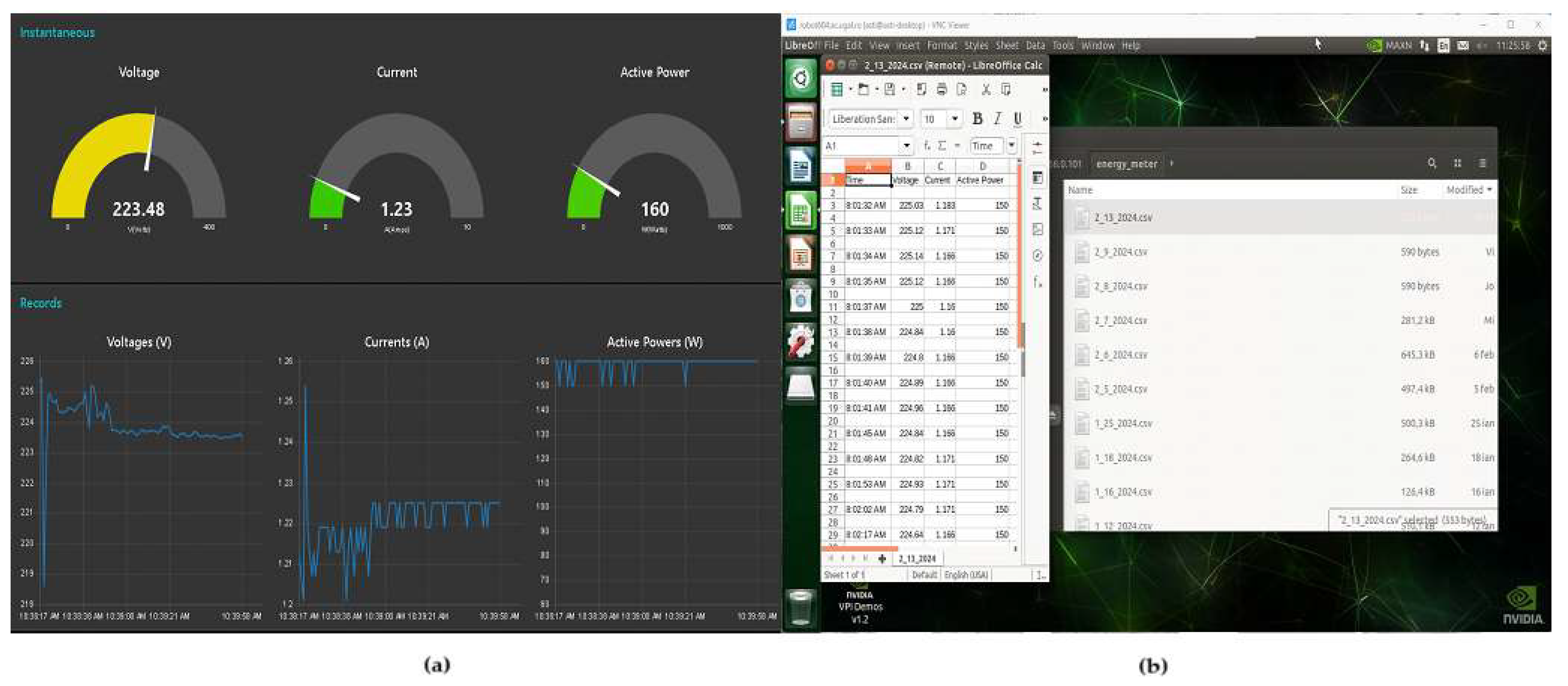
Through the specialized communication device, IOT 2050, Node-RED flow (
Figure 20) and virtual network computing (VNC), instantaneous and time horizon electrical data, current, voltage and power (
Figure 21a) can be acquired and stored into Cloud, and into the embedded computer (
Figure 21b), for remote and local monitoring, respectively, useful for the prevention of breakdowns and maintenance. The ABB 120 IRM Teach Pendant (4A in
Figure 1) has installed a VNC server where the user can connect remotely using the
VNC Viewer desktop application. The NVIDIA Jetson Nano also has a VNC server running on it, and the user can access this server to work on it remotely if needed. NVIDIA Jetson Nano is a small, powerful computer for embedded AI-ML’s applications. IoT 2050 delivers more power communication between embedded computer and remote PC (A/D/R Display device, 9) in
Figure 1), and Cloud platform. Because the communication is wireless, meaning that the speed may not be good, and the VNC window might freeze because of that. Due to this reason, to increase speed of communication, is to connect with an ethernet cable to the Siemens Simatic SCALANCE XB005 switch, on the last available port, LAN P2. Therefore, we set a static IP address on the local PC, {
40,
41,
42,
43].
4.4. Machine Learning for Adaptive Control, Optimization and Predictive Mainetance
A machine learning algorithm processes the electrical data acquired from the robotic system, power consumption, motor current, and voltage levels (from the motors in the joints of ABB IRM and the motor that drives the conveyor belt), to create an adaptive model, with parameters updated online (gradient update law), that optimize the system’s performance. The system learns from historical data to improve energy efficiency, reduce wear on mechanical parts, and adjust control strategies in real-time. AI-based machine learning techniques are used to detect anomalies in electrical parameters, helping to prevent malfunctions or unexpected downtime. By continuously learning from operational data, the system can predict faults and recommend corrective actions before they impact productivity.
5. Discussion
The IoT-Cloud platform enables real-time monitoring and control of the A/D/R MRC by integrating sensors, control systems, and data streams across the cloud. Also, IoT-Cloud platform allows remote access to real-time data and control capabilities, data analytics for optimized task scheduling and diagnostics and cloud storage for historical data and predictive analysis. VPN ensures secure communication between the control center and the robotic system, allowing authorized users to access and control the system remotely while maintaining data privacy and provide support and troubleshoot the system from any location. The digital twin integrates augmented reality (AR), offering user an enhanced view of the MRC in real-world settings. AR is used to visualize and simulate A/D/R tasks, provide real-time instructions and feedback on task performance, optimize task sequences, and reduce errors through visual aids. Virtual reality (VR) combined with STPN provides a simulated environment to model task workflows and system operations. This allows operators or students to: Experience the system virtually, exploring the behavior of the robotic cell in various task scenarios. Analyze task timings and dependencies using STPN to identify workflow optimizations. The HMIs dashboard serve as the primary user interface for interacting with the system, displaying real-time data on ABB IRM movements, task progress, and system status. Also. the HMIs dashboards enable manual control of task workflows. and real-time visualization of key performance indicators. The SCADA system oversees the MRC operations, allowing data acquisition from sensors, and devices, real-time monitoring and alarm control, and historical data logging for performance analysis. OPC UA is the backbone of the system’s communication architecture, ensuring seamless data exchange between ABB IRM, IoT edge devices, and the control system. This standard protocol provides cross-platform interoperability between devices, efficient and reliable data sharing for control and monitoring tasks, easy integration of IoT edge devices into the system.
6. Conclusions
This advanced system combines multiple technologies to enable remote and local monitoring, task planning, and control of an A/D/R MRC. The A/D/R MRC is centred around a 6-DOF ABB 120 IRM, designed for assembly, disassembly, and replacement operations in both industry and educational settings. The system incorporates modern technologies, including IoT-Cloud, VPN, DT, AR, VR with STPN, HMI, SCADA, OPC UA, and a ML method for adaptive electrical data learning, aligning with Industry and Education 4.0 and 5.0 principles. The integration of IoT-Cloud, ML, real-time monitoring and control aligns with Industry 4.0, where the focus is on the automation and optimization of industrial systems. The system provides full remote control, enabling real-time decision-making and automated adjustments based on predictive analytics and maintenance. Instead, Industry 5.0, considered an extension of Industry 4.0, emphasizes collaboration between humans and machines. The system’s use of augmented and virtual reality, as well as machine learning, allows operators to work closely with robotic systems, offering personalized and human-centric interactions. emphasizes collaboration between humans and machines.
Thus, the contributions and results obtained, up to now, will be the following:
Multilevel architecture, hardware and software setup,
DT approach based on AR for task planning and VR with STPN models, formalism and simulation,
Remote and local HMI, SCADA, OPC-UA and Cloud platform,
Real-time monitoring and control of A/D/R MRC,
Electrical data acquisition, remote and local storage for preventive maintenance by adaptive ML,
Statement the compatibilities of A/D/R MRC with Industry and Education 4.0 and 5.0.
In the context of AI and Industry 4.0/5.0, in the future, the research focuses on:
Integration AI to improve the decision-making process,
AI-driven predictive analytics for identifying potential issues and optimizing task planning,
real-time machine learning to adapt control strategies based on the data generated by the MRC,
AI integration with DT for simulating different operational scenarios and identifying the most efficient workflows.
In the context of Education 4.0 and 5.0, in the future, the research focuses on:
Remote learning opportunities where students can interact with the system through AR, VR, and digital twins.
Hands-on experience with real-world technologies, such as machine learning, SCADA, OPC UA, and IoT, in a controlled laboratory setting.
Collaborative learning platforms where students can experiment with the system from anywhere, preparing them for the future of smart manufacturing.
Author Contributions
Conceptualization, all authors; methodology: A.F. (Adrian Filipescu), D.I., A.F. (Adriana Filipescu), and G.S.; software: G.S. and D.I.; validation: A.F. (Adrian Filipescu); formal analysis: G.S. D.I., and A.F. (Adriana Filipescu); writing—original draft preparation: A.F. (Adrian Filipescu), and A.F. (Adriana Filipescu); writing—review and editing: A.F. (Adrian Filipescu), A.F. (Adrian Filipescu); project administration: A.F. (Adrian Filipescu); funding acquisition, A.F. (Adrian Filipescu). All authors have read and agreed to the published version of the manuscript
Funding
This article (APC) will be supported by “Dunărea de Jos” University of Galati.
Institutional Review Board Statement
Not applicable.
Informed Consent Statement
Not applicable.
Data Availability Statement
Data availability is not applicable to this article as the study did not report any data.
Acknowledgments
In this section, you can acknowledge any support given which is not covered by the author contribution or funding sections. This may include administrative and technical support, or donations in kind (e.g., materials used for experiments).
Conflicts of Interest
The authors declare no conflicts of interest.
References
- Guiras, Z.; Turki, S.; Rezg, N.; Dolgui, A. Optimization of Two-Level Disassembly/Remanufacturing/Assembly System with an Integrated Maintenance Strategy. Appl. Sci. 2018, 8, 666. [Google Scholar] [CrossRef]
- Filipescu, A.; Ionescu, D.; Filipescu, A.; Mincă, E.; Simion, G. Multifunctional Technology of Flexible Manufacturing on a Mechatronics Line with IRM and CAS, Ready for Industry 4.0. Processes 2021, 9, 864. [Google Scholar] [CrossRef]
- Ionescu, D.; Filipescu, A.; Simion, G.; Mincă, E.; Cernega, D.; Șolea, R.; Filipescu, A. Communication and Control of an Assembly, Disassembly and Repair Flexible Manufacturing Technology on a Mechatronics Line Assisted by an Autonomous Robotic System. Inventions 2022, 7, 43. [Google Scholar] [CrossRef]
- Chryssolouris, G. Manufacturing Systems—Theory and Practice; Springer: New York, NY, USA, 2005. [Google Scholar]
- Tolio, T. Design of Flexible Production Systems—Methodologies and Tools; Springer: Berlin/Heidelberg, Germany, 2009. [Google Scholar]
- Mincă, E.; Filipescu, A.; Cernega, D.; Șolea, R.; Filipescu, A., Jr.; Ionescu, D.; Simion, G. Digital Twin for a Multifunctional Technology of Flexible Assembly on a Mechatronics Line with Integrated Robotic Systems and Mobile Visual Sensor—Challenges towards Industry 5.0. Sensors 2022, 22, 8153. [Google Scholar] [CrossRef] [PubMed]
- Carlos-Mancilla, M.A.; Luque-Vega, L.F.; Guerrero-Osuna, H.A.; Ornelas-Vargas, G.; Aguilar-Molina, Y.; González-Jiménez, L.E. Educational Mechatronics and Internet of Things: A Case Study on Dynamic Systems Using MEIoT Weather Station. Sensors 2021, 21, 181. [Google Scholar] [CrossRef]
- Florescu, A.; Barabas, S.A. Modeling and Simulation of a Flexible Manufacturing System—A Basic Component of Industry 4.0. Appl. Sci. 2020, 10, 8300. [Google Scholar] [CrossRef]
- Berriche, A.; Mhenni, F.; Mlika, A.; Choley, J.-Y. Towards Model Synchronization for Consistency Management of Mechatronic Systems. Appl. Sci. 2020, 10, 3577. [Google Scholar] [CrossRef]
- Minca, E.; Filipescu, A.; Voda, A. Modelling and control of an assembly/disassembly mechatronics line served by mobile robot with manipulator. Control Eng. Pract. 2014, 31, 50–62. [Google Scholar] [CrossRef]
- Filipescu, A.; Filipescu, A., Jr. , Simulated Hybrid Model of an Autonomous Robotic System Integrated into Assembly/Disassembly Mechatronics Line. IFAC Proc. Vol. 2014, 47, 9223–9228. [Google Scholar] [CrossRef]
- Dragomir, F.; Mincă, E.; Dragomir, O.E.; Filipescu, A. Modelling and Control of Mechatronics Lines Served by Complex Autonomous Systems. Sensors 2019, 19, 3266. [Google Scholar] [CrossRef]
- Filipescu, A.; Mincă, E.; Filipescu, A.; Coandă, H.-G. Manufacturing Technology on a Mechatronics Line Assisted by Autonomous Robotic Systems, Robotic Manipulators and Visual Servoing Systems. Actuators 2020, 9, 127. [Google Scholar] [CrossRef]
- Filipescu, A.; Minca, E.; Filipescu, A. Mechatronics Manufacturing Line with Integrated Autonomous Robots and Visual Servoing Systems. In Proceedings of the 9th IEEE International Conference on Cybernetics and Intelligent Systems, and Robotics, Automation and Mechatronics (CIS-RAM 2019), Bangkok, Thailand, 18–20 November 2019; pp. 620–625. [Google Scholar] [CrossRef]
- Minca, E.; Filipescu, A.; Coanda, H.G.; Dragomir, F.; Dragomir, O.E.; Filipescu, A. Extended Approach for Modeling and Simulation of Mechatronics Lines Served by Collaborative Mobile Robots. In Proceedings of the 22nd International Conference on System Theory, Control and Computing (ICSTCC), Sinaia, Romania, 10–12 October 2018; pp. 335–341. [Google Scholar]
- Segovia, M.; Garcia-Alfaro, J. Design, Modeling and Implementation of Digital Twins. Sensors 2022, 22, 5396. [Google Scholar] [CrossRef] [PubMed]
- Moiceanu, G.; Paraschiv, G. Digital Twin and Smart Manufacturing in Industries: A Bibliometric Analysis with a Focus on Industry 4. 0. Sensors 2022, 22, 1388. [Google Scholar] [CrossRef] [PubMed]
- Filipescu, A.; Cernega, D.; Solea, R.; Filipescu, A.; Minca, E.; Ionescu, D.; Simion, G. Modeling and Control an A/DT Served by an ACPS based on SCADA, Industry 4.0 and 5.0. 28th IEEE International Conference on Emerging Technologies and Factory Automation, ETFA 2023, ISSN: 1946-0759. Sinaia, 12-15 September 2023; 15 September 2023. [Google Scholar] [CrossRef]
- Filipescu, A.; Simion, G.; Ionescu, D.; Filipescu, A. Remote Control of a Flexible Robotic Cell as a Cyber Physical System for Assembly and Disassembly based on SCADA and Industry 4.0. The 32nd Mediterranean Conference on Control and Automation, Chania, Crete, Greece, 11–14 June 2024. [Google Scholar] [CrossRef]
- Filipescu, A.; Stamatescu, I.; Simion, G.; Ionescu, D.; Filipescu, A. IoT-Cloud based Control of a Flexible Assembly/Disassembly Mechatronic System in the Framework of Industries 4.0 and 5.0. IEEE 18th International Conference on Control & Automation (ICCA), Reykjavík, Iceland, 18-21 June 2024. [Google Scholar] [CrossRef]
- Martinez, E.M.; Ponce, P.; Macias, I.; Molina, A. Automation Pyramid as Constructor for a Complete Digital Twin, Case Study: A Didactic Manufacturing System. Sensors 2021, 21, 4656. [Google Scholar] [CrossRef] [PubMed]
- Bamunuarachchi, D.; Georgakopoulos, D.; Banerjee, A.; Jayaraman, P.P. Digital Twins Supporting Efficient Digital Industrial Transformation. Sensors 2021, 21, 6829. [Google Scholar] [CrossRef]
- Vachálek, J.; Šišmišová, D.; Vašek, P.; Fiťka, I.; Slovák, J.; Šimovec, M. Design and Implementation of Universal Cyber-Physical Model for Testing Logistic Control Algorithms of Production Line’s Digital Twin by Using Color Sensor. Sensors 2021, 21, 1842. [Google Scholar] [CrossRef]
- Gallala, A.; Kumar, A.A.; Hichri, B.; Plapper, P. Digital Twin for Human–Robot Interactions by Means of Industry 4.0 Enabling Technologies. Sensors 2022, 22, 4950. [Google Scholar] [CrossRef]
- Stączek, P.; Pizoń, J.; Danilczuk, W.; Gola, A. A Digital Twin Approach for the Improvement of an Autonomous Mobile Robots (AMR’s) Operating Environment—A Case Study. Sensors 2021, 21, 7830. [Google Scholar] [CrossRef]
- Abdul Hadi, M.; Kraus, D.; Kajmakovic, A.; Suschnigg, J.; Guiza, O.; Gashi, M.; Sopidis, G.; Vukovic, M.; Milenkovic, K.; Haslgruebler, M.; et al. Towards Flexible and Cognitive Production—Addressing the Production Challenges. Appl. Sci. 2022, 12, 8696. [Google Scholar] [CrossRef]
- Angelopoulos, J.; Mourtzis, D. An Intelligent Product Service System for Adaptive Maintenance of Engineered-to-Order Manufacturing Equipment Assisted by Augmented Reality. Appl. Sci. 2022, 12, 5349. [Google Scholar] [CrossRef]
- Mourtzis, D.; Angelopoulos, J.; Panopoulos, N. A Literature Review of the Challenges and Opportunities of the Transition from Industry 4.0 to Society 5.0. Energies 2022, 15, 6276. [Google Scholar] [CrossRef]
- Zizic, M.C.; Mladineo, M.; Gjeldum, N.; Celent, L. From Industry 4.0 towards Industry 5.0: A Review and Analysis of Paradigm Shift for the People, Organization and Technology. Energies 2022, 15, 5221. [Google Scholar] [CrossRef]
- Nahavandi, S. Industry 5.0—A Human-Centric Solution. Sustainability 2019, 11, 4371. [Google Scholar] [CrossRef]
- Radaschin, A.; Voda, A.; Minca, E.; Filipescu, A. Task Planning Algorithm in Hybrid Assembly/Disassembly Process. In Proceedings of the 14th IFAC Symposium on Information Control Problems in Manufacturing, Bucharest, Romania, 23–25 May 2012. [Google Scholar]
- Kallrath, J. Planning and scheduling in the process industry. In Advance Planning and Scheduling Solution in Process Industry; Springer: Berlin/Heidelberg, Germany, 2003; pp. 201–227. [Google Scholar]
- He, Y.; Stecke, K.E.; Smith, M.L. ; Robot and machine scheduling with state-dependent part input sequencing in flexible manufacturing systems. Int. J. Prod. Res. 2016, 54, 6736–6746. [Google Scholar] [CrossRef]
- Barczak, A.; Dembińska, I.; Marzantowicz, Ł. Analysis of the Risk Impact of Implementing Digital Innovations for Logistics Management. Processes 2019, 7, 815. [Google Scholar] [CrossRef]
- Gasparetto, A.; Zanotto, V. A new method for smooth trajectory planning of robot manipulators. Mech. Mach. Theory 2007, 42, 455–471. [Google Scholar] [CrossRef]
- Node-RED web-based flow editor for remote control, Node-RED 4.0 released - News - Node-RED Forum (nodered.org) (accessed on 24 October 2024).
- Sirphyco Simulateur de Réseaux de Petri, Sirphyco-Simulateur-de-Reseaux-de-Petri. Available online: Toucharger.com (accessed on 11 October 2024).
- Mathworks. Available online: https://www.mathworks.com (accessed on 11 October 2024).
- Totally Integrated Automation Portal, TIA Portal V17, Available online:. Available online: www.siemens.com/tia-portal (accessed on 11 October 2024).
- OpenCV. Available online: https://opencv.org (accessed on 11 October 2024).
- Microsoft Visual Studio. Available online: https://www.visualstudio.com/vs/cplusplus (accessed on 11October 2024).
- SCADA System SIMATIC, WinCC SIMATIC WinCC V7 / V8 - Siemens Xcelerator Global. (accessed on 11 October 2024). (accessed on null).
- VNC (Virtual Network Computing), RealVNC® - Remote access software fo r desktop and mobile | RealVNC. (accessed on 11 October 2024). (accessed on null).
Figure 1.
IoT Edge Devices and LAN/WAN Networking.
Figure 1.
IoT Edge Devices and LAN/WAN Networking.
Figure 4.
Node-RED assembly task planning as augmented reality.
Figure 4.
Node-RED assembly task planning as augmented reality.
Figure 5.
Node-RED disassembly task planning as augmented reality.
Figure 5.
Node-RED disassembly task planning as augmented reality.
Figure 6.
Node-RED cylinder replacement task planning as augmented reality.
Figure 6.
Node-RED cylinder replacement task planning as augmented reality.
Figure 7.
The STPN model as VR for assembly.
Figure 7.
The STPN model as VR for assembly.
Figure 8.
Sirphyco simulation of the STPN model for the assembly.
Figure 8.
Sirphyco simulation of the STPN model for the assembly.
Figure 9.
STPN model as VR for disassembly.
Figure 9.
STPN model as VR for disassembly.
Figure 10.
Sirphyco simulation of STPN model for the disassembly.
Figure 10.
Sirphyco simulation of STPN model for the disassembly.
Figure 11.
STPN model as VR for replacing cylinders.
Figure 11.
STPN model as VR for replacing cylinders.
Figure 12.
Sirphyco simulation of the STPN model for replacing one cylinder.
Figure 12.
Sirphyco simulation of the STPN model for replacing one cylinder.
Figure 13.
Sirphyco simulation of the STPN model for replacing both cylinders.
Figure 13.
Sirphyco simulation of the STPN model for replacing both cylinders.
Figure 14.
Monitoring signals (flanking transitions) from the PLC for assembly.
Figure 14.
Monitoring signals (flanking transitions) from the PLC for assembly.
Figure 15.
Monitoring signals (flanking transitions) from the PLC for disassembly.
Figure 15.
Monitoring signals (flanking transitions) from the PLC for disassembly.
Figure 16.
Monitoring signals (flanking transitions) from the PLC for replacing one cylinder.
Figure 16.
Monitoring signals (flanking transitions) from the PLC for replacing one cylinder.
Figure 17.
Monitoring signals (flanking transitions) from the PLC for replacing both cylinders.
Figure 17.
Monitoring signals (flanking transitions) from the PLC for replacing both cylinders.
Figure 18.
The Node-RED flow for the images captured from cameras: warehouses and parts.
Figure 18.
The Node-RED flow for the images captured from cameras: warehouses and parts.
Figure 19.
The Node-RED images captured from cameras; (a) warehouse with pallets; (b) the warehouse with metal cylinders and the one with plastic cylinders; (c) warehouses with bodies, with tops with square edges (Top_sq) and with tops with round edges (Top_rd), respectively.
Figure 19.
The Node-RED images captured from cameras; (a) warehouse with pallets; (b) the warehouse with metal cylinders and the one with plastic cylinders; (c) warehouses with bodies, with tops with square edges (Top_sq) and with tops with round edges (Top_rd), respectively.
Figure 20.
The Node-RED flow for displaying and storing electrical data of the MRC.
Figure 20.
The Node-RED flow for displaying and storing electrical data of the MRC.
Figure 21.
(a) Representation of gouge (instantaneous) and plot (records) of electrical data of MRC; (b) The Virtual Network Computing (VNC)-Viewer MRC’s Electrical Recorded Data in the embedded computer (edge device).
Figure 21.
(a) Representation of gouge (instantaneous) and plot (records) of electrical data of MRC; (b) The Virtual Network Computing (VNC)-Viewer MRC’s Electrical Recorded Data in the embedded computer (edge device).
|
Disclaimer/Publisher’s Note: The statements, opinions and data contained in all publications are solely those of the individual author(s) and contributor(s) and not of MDPI and/or the editor(s). MDPI and/or the editor(s) disclaim responsibility for any injury to people or property resulting from any ideas, methods, instructions or products referred to in the content. |
© 2024 by the authors. Licensee MDPI, Basel, Switzerland. This article is an open access article distributed under the terms and conditions of the Creative Commons Attribution (CC BY) license (http://creativecommons.org/licenses/by/4.0/).