
Submitted:
03 December 2024
Posted:
04 December 2024
You are already at the latest version
Abstract
This paper deals with a “Digital Twin” (DT) approach for a processing, reprocessing and scrapping (P/R/S) technology running on a modular production system (MPS) assisted by a mobile cyber-physical robotic system (MCPRS). The main hardware architecture consists of four-workstations (WSs), line-shaped, a wheeled mobile robot equipped with a robotic manipulator (RM) and a mobile visual servoing system (MVSS) mounted on the end effector. The system architecture integrates a hierarchical control system where each of the four WSs, in the MPS, is controlled by a PLC, all connected via Profibus DP to a central PLC. In addition to the connection via Profibus of the four PLCs, related to the WSs, to the main PLC, there are also the connections of the other devices to the local networks, LAN-Profinet and LAN-Ethernet and the connection to the Internet via WAN-Ethernet by open platform communication unified architecture (OPC-UA). The overall system follows a DT approach that enables task planning through augmented reality (AR) and uses virtual reality (VR) for visualization through Synchronized Hybrid Petri Nets (SHPN) simulation. Timed Petri Nets (TPN) are used for controlling the processes within the MPS’s workstations. Continuous Petri Nets (CPN) handle the movement of the MCPRS. Task planning in AR enables user to interact with the system in real-time using AR technology to visualize and plan tasks. SHPN in VR is combination between TPN and CPN used in the virtual representation of the system for synchronizing tasks between the MPS and MCPRS. The workpiece (WP) visits stations successively as it is moved along the line for processing. If the processed WP does not pass the quality test, it is taken from the last WS and is transported, by MCPRS, to the first WS where it will be considered for reprocessing or scrapping.
Keywords:
MPS
; MCPRS
; WMR
; RM
; MVSS
; SHPN
; DT
; AR
; VR
; profibus
; profinet
; ethernet
1. Introduction
Cloud and Virtual Private Network (VPN)-based remote-control system for a Modular Production System (MPS), consisting of four workstations that handle processes such as buffering, processing, sorting/storage, reprocessing, and scrapping is presented in this paper. This system is assisted by a Mobile Cyber-Physical Robotic System (MCPRS), [1,2,3]. The “Digital Twin” (DT) approach, in this system, integrates both physical and virtual components to enhance process monitoring, task planning, and overall system control. The system involves: MPS with four WSs, arranged in a line-shaped configuration and MCPRS consisting of a two driving wheels/one free wheel (2DW/1FW) WMR, a 7-DOF RM, and a MVSS with a camera on the RM’s end effector. This architecture enables the processing, reprocessing, or scrapping of WPs as they move through the production line, using both real-world hardware and a virtual twin for optimized performance. DT integration consists of a combination of AR for task planning and VR for real-time visualization and simulation. AR for task Planning uses Node-RED functions to facilitate user interaction, allowing remote task to set up and validation through an AR interface. VR and simulation use SHPN through the Sirphyco package for dynamic simulations, which include both TPN for the fixed MPS’s WSs and CPN for MCPRS movement control.
The system objectives are:
- Processing: WP is processed sequentially at stations such as buffering, handling, processing, and sorting/storage.
- Reprocessing: WP failing the Primary Quality Test (PQT) at the sorting and storage WS are transported back by the MCPRS to the buffer WS. This WP undergoes a second cycle of processing to meet quality standards.
- Scrapping: WP failing the Secondary Quality Test (SQT) at the handling WS are classified as scrap. MCPRS ensures these defective WPs are segregated for disposal, maintaining production flow efficiency.
- Remote Accessibility: Cloud/VPN-based interfaces provide real-time monitoring and control. User can observe, plan, and adjust tasks remotely, ensuring flexible and scalable production User interacts visually with production systems via AR-enhanced HMIs. AR facilitates real-time visualization of robotic and WS operations, enabling task.
Although the remote control of P/R/S technology is designed to work on a laboratory structure, MPS assisted by MCPRS, has a counterpart in the real world, especially in industries where the recovery and reuse of components is one of the objectives. Across industries, we are seeing more use of DT in manufacturing. DT visualization technology pairs well with the sensors that manufacturers use to gather vital information on production processes. Now, the information collected via smart manufacturing systems can be incorporated into visual, interactive models.
MCPRS could find applicability in multiple areas like as mobile intelligent robots, manufacturing robotic systems, educational mobile devices, intelligent service and IoT-cloud robots’ control. MCPRS could improve efficiency and scalability in processing complex tasks that are impossible under local resource constraints in different applications, [1,2]. The MCPRS functions as a mobile cyber-physical system, intertwining hardware and software for adaptive, real-time operations. The system adjusts dynamically to context changes, ensuring robust and efficient performance, deeply connects computational algorithms and physical processes ensure synchronization. MCPRS can operate at different spatial and temporal scales, exhibiting multiple and distinct behavioral modalities, and interacting with each other in context-changing ways, [1,2,3,4,5,6,7,8,9,10].
DT in manufacturing, also known as a digital replica, is a virtual copy of a real-world component in the manufacturing process. The DT approach enables the real-time digital representation of the entire system, ensuring synchronization between the physical and virtual components. The virtual counterpart includes AR for task planning and SHPN model simulation as VR. Task planning is enhanced with AR technology, allowing users to interact with the production system visually. Through Node-RED functions, users can visualize real-time processes and plan or modify tasks by interacting with virtual WSs and robotic systems. Users can observe how the MCPRS moves, picks, and places WP, or how each WS handles its respective processing tasks. They can also simulate workflow changes to predict performance. VR by SHPN model simulation combines TPNs and CPNs in a virtual environment, representing the MPS and MCPRS’s movement together. The MPS's workstations are controlled by TPN, which models the discrete processes at each station. These include WP’s loading, buffing, handling, transferring between stations, main processing operations, sorting and evaluating quality. The MCPRS’s movement is governed by CPN, representing the dynamic displacement and operation of the WMR, RM and MVSS, [11,12,13,14,15,16,17,18].
The real world consists of communication, synchronization, monitoring, and control of a processing technology with product recovery by reprocessing that works on a laboratory system and integrates several subsystems, namely 4-WS FESTO MPS-200 mechatronics line assisted by MCPRS that consists of an autonomous robotic system, PeopleBot WMR equipped with a 7-DOF Cyton1500 RM and an MVSS located on the end effector with a Logitech camera. All these subsystems are equipped with PLCs, wired and wireless communication devices, infrared, inductive, and optical sensors, electric and pneumatic actuators. The technology assisted by MCPRS is of pipeline type, allowing processing operations, quality tests, reprocessing with the same operations or complete rejection if the workpiece is completely compromised, [18,19,20,21,22,23,24,25,26,27]. A combination of between
TPNs and CTNs is used in the virtual representation of the system for synchronizing tasks between the MPS and MCPRS. This enables the coordination of discrete-event processes with continuous movement in a unified framework.
A SCADA system is integrated into the system for real-time control and automation. SCADA gathers data from IoT sensors, actuators on MPS and other devices to provide real-time feedback to the user. SCADA system allows user to monitor and control the MCPRS’s movements, the sequencing of MPS processing operation, and the status of connected devices. SCADA interfaces provide visualizations of the MPS and MCPRS status, showing real-time data such as WP positions, actuator states, and task progression. User can involve this data to make informed decisions.
Two HMIs (Human-Machine Interfaces) are designed, allowing users to interact, remote or local, with the MPS (HMI-MPS) and MCPRS (HMI-MCPRS). The HMIs provide real-time feedback from SCADA, DT, IoT sensors and detailed information about MRC status, including the workpiece’s A/D/R progress.
OPC-UA is integrated to ensure standardized and secure communication between various IoT devices. It enables interoperability between different systems, MPS 200, MCPRS, IoT sensors, PLCs, embedded computer, IoT gateway, HMI-MPS, HMI-MCPRS, and cloud -platform. OPC-UA acts as a bridge between the local control systems (SCADA, HMIs) and the cloud-based infrastructure, facilitating smooth data flow, P/R/S coordination and real-time communication.
The rest of the paper is organized in six sections. Hardware structure of MPS assisted by MCPRS, for remote or local monitoring and control multilevel architecture based on IoT edge devices, Profibus, LAN, WAN Networking, Cloud, VPN connections, and assumptions, is presented in Section 2. In Section 3, Digital Twin’s virtual world counterpart of MPS and MCPRS, together with task planning as AR and SHPN models, formalism and simulation, as VR, all of these for P/R/S technology and MCPRS displacement, are presented in Section 3. SCADA, HMIs synchronization, Cloud and VPN and real-time control are presented in Section 4. Several remarks about the approach, effectiveness, user experience and cyber security can be found in Section 5, Discussion. Final remarks, and paper contributions are stated in Section 6, Conclusions.
2. Hardware Architecture of MPS with MCPRS Assistance
2.1. Main Devices and Functinalites
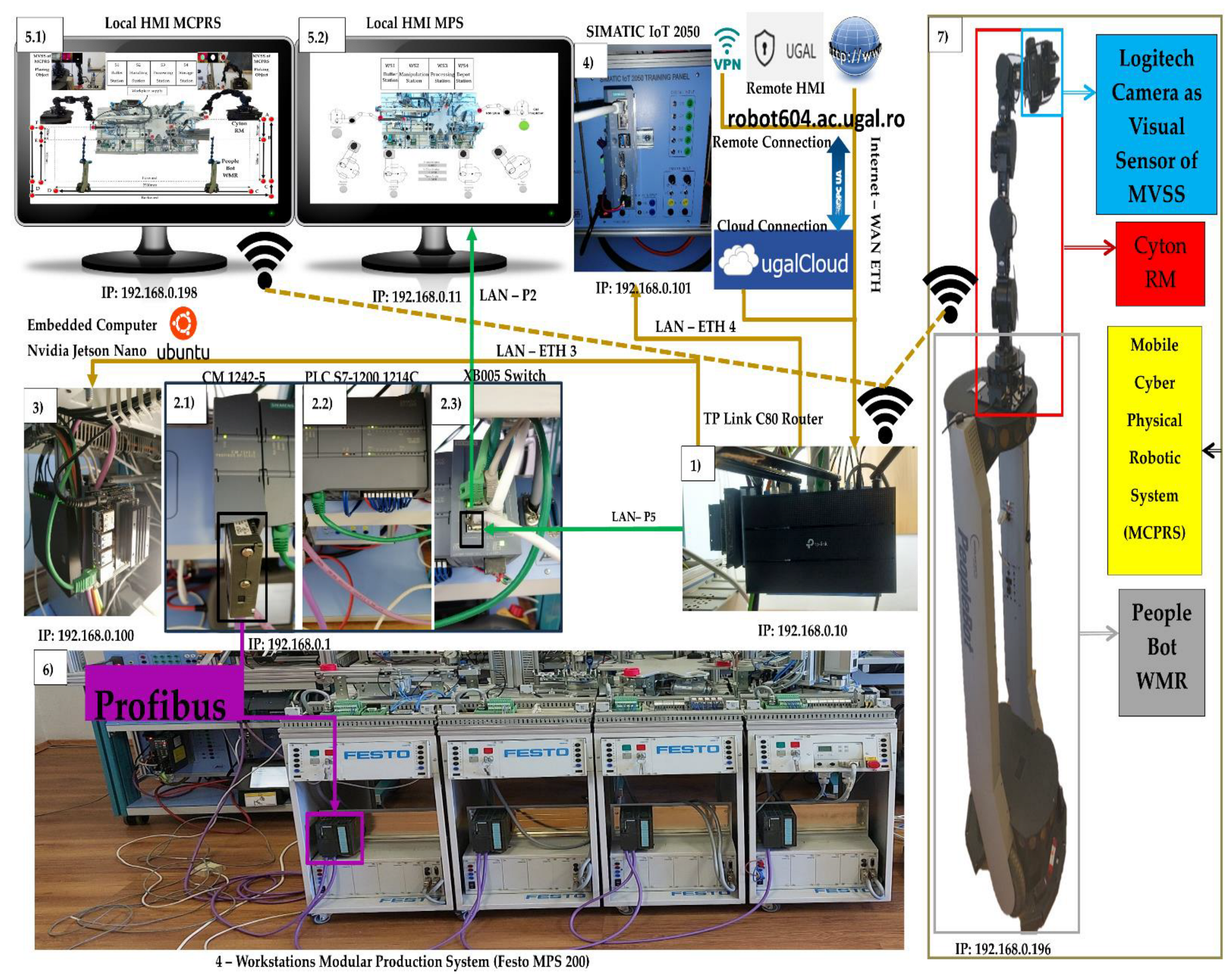
Modular Production System (Festo MPS 200), shown in Figure 1 consists of four WSs that handle processes such as buffering, handling, processing, sorting/storage, reprocessing, and scrapping. These WSs are controlled by separate Siemens S7 300 PLC, connected via Profibus, to a master PLC, S7-1200, each of them ensures operations in different stages, as is shown in Figure 2. This system is assisted by MCPRS which includes: 2DW/1FW PeopleBot WMR, 7-DOF Cyton 1500 RM, mounted on the WMR, and MVSS with a Logitech camera mounted on the last link of the Cyton RM.
Siemens S7-1200 PLC serves as the master PLC in this system whose role is to:
- coordinate and controls the overall production flow across the four WSs,
- control communication between the MPS’s WSs (buffer, handling, processing, sorting/storage) and MCPRS,
- control task synchronization between MPS operation and MCPRS.
- interfaces with remote systems over OPC-UA, WAN-Ethernet, and other networks for cloud-based SCADA and HMI control.
Each MPS’s WS is controlled by a dedicated SIEMENS S7-300 PLC, which functions as a slave PLC, whose role is to:
- be responsible for the operations within its respective WS,
- communicate with the master S7-1200 PLC via Profibus, which facilitates synchronized, real-time control of individual WS’s tasks,
- send status, update and task completion to the master PLC, allowing centralized decision-making.
2.2. IoT Edge Devices, Profibus, Profinet, LAN Ethernet, WAN Ethernet and Networking
In Figure 2, it is displayed all the devices connected to the Profibus and LANs, Profinet and Ethernet, each device having its own unique IP address. 1). WI-FI router (TP-Link Archer) has the role of WI-FI network management, assures LAN Profinet, Ethernet, and WAN-Ethernet connectivity to the Cloud via Internet. 2.1). Communications module SIMATIC CM 1242-5, attached to S7-1214 PLC, is used for connection of the SIMATIC S7-300 PLCs to Profibus (DP slave module) 2.2). SIEMENS PLC 1214C DC/DC/DC as master and HMI’s main control unit, allows all other devices to communicate with it, manages all signals (on sensors or from communication) and internal variables which are used by remote and local SCADA system. 2.3). Communication adapter XB005 Switch, attached to S7-1214 PLC is used for connecting, via LAN-Profinet, to digital ports the following devices: to P2, secondary local SCADA-HMI MPS-MPS display devices; to P5, WI-FI router. 3). Embedded computer NVIDIA Jetson Nano has a Virtual Network Computing (VNC) server running on it, and VNC Viewer is enabled for remote connection. Jetson Nano has access to all the other devices and web browser for Node-RED interface. 4). SIEMENS IOT2050 is used as remote SCADA System, send/receive data to/from PLC. 5.1). Local SCADA HMI MPS-MCPRS display device, which monitors and controls MCPRS and its interaction with MPS workstations, WS4 and WS1by synchronization signals. 5.2). Local SCADA HMI MPS-MPS display device, which monitors and controls MPS’s WSs and their interaction with MCPRS, especially with WS4 and WS1 by synchronization signals. 6). Dedicated slave SIEMENS S7-300 PLCs, one for each WS.
Figure 2.
IoT Edge Devices, Profibus DP, LAN Profinet, LAN Ethernet, WAN Ethernet and Networking.
2.3. Profibus, LAN-Profinet, LAN-Ethernet and WAN-Ethernet Communication Networks
The communication system is robust and supports real-time control and monitoring across the MPS WSs and the MCPRS. Profibus DP is a deterministic communication protocol used to connect four Siemens S7-300 PLCs at each WS to the central Siemens S7-1214 PLC, enabling high-speed data transmission and precise control. LAN-Profinet is the local industrial Ethernet network used for high-speed, real-time communication between the main controller (S7-1200) and other devices, ensuring deterministic communication in industrial operations. LAN-Ethernet handles general data traffic that is not time-sensitive, allowing for reliable data communication between less critical devices. WAN-Ethernet provides the external internet connection, enabling the system to be monitored and controlled remotely via the VPN. OPC-UA is a standardized communication protocol used for secure and reliable communication between industrial devices. OPC-UA is particularly useful for connecting the system to cloud services and ensuring interoperability between different manufacturers’ devices.
2.4. Multilevel Architecture of MPS Assisted by MCPRS
The control structure, shown in Figure 3, is multilevel as follows:
1, Cloud/VPN remote operation level: This level includes SCADA and two HMIs systems (HMI-MPS and HMI-MCPRS) for both the MPS 200 and the MCPRS. Through a secure VPN connection, users can monitor and control the entire system remotely, accessing real-time data, triggering commands, or troubleshooting any issues. Node-RED enhances this level by providing a customizable dashboard for AR-based task planning, allowing operators to visualize workflows and system performance remotely.
2. Local operation level and Task Flow. On-site task planning is performed using a chart flow system that coordinates and manages processes. Local SCADA/HMIs: User at the site can monitor and interact with the system via local interfaces, HMI-MPS and HMI-MCPRS, making it easy to adjust tasks and oversee processes in real-time.
3. Communication level and embedded computer, Jetson Nano. Acts as an on-board computer for real-time data processing, vision processing for the MVSS, and controls the robotic tasks of the MCPRS. TP-Link C80 router handles communication within the local network and connects to external networks for broader data exchange. SIEMENS -IoT 2050 gateway facilitates communication between industrial devices (PLCs, sensors, and actuators) and the cloud, enabling seamless integration with cloud-based services and remote control.
4. Control level and Siemens S7-1214 PLC as main control unit. This is the primary control unit for the entire system. It manages the operation of the MPS 200 and communicates with the other PLCs and devices. CM 1242 Profibus DP adapter connects the S7-1200 PLC to the distributed S7-300 PLCs across the four workstations via the Profibus DP protocol, enabling fast and reliable control across the network. Switch: Manages Ethernet traffic between devices in the control network. Four Siemens S7-300 PLCs: Each workstation (buffer, handling, processing, sorting/storage) is controlled by a dedicated Siemens S7-300 PLC, providing precise control over the respective task processes.
5. Process level, MPS 200 WSs, and MCPRS. Each of the four workstations (buffer, handling, processing, sorting/storage) handles a specific phase in the production line, with the S7-300 PLCs coordinating the operations at each station.
The control MCPRS within the modular production environment is multifaceted, integrating both discrete and continuous control systems to manage the mobility, manipulation, and visual servoing required for MCPRS tasks. The purpose is to allow the MCPRS to assist in operations across the WS1 and WS4 along the MPS 200 especially for transporting, reprocessing, and scrapping defective WPs, as is shwon in Figure 4.
Only one type of workpiece, but of different colors (silver, red and black), is processed, reprocessed, or scrapped, because the P/R/S technology involves processing operations specific to a certain type of product. By convention, a silver WP is considered to pass the primary quality test after processing and is stored on the middle or bottom shelf of the storage station (WS4). By convention, it is considered that the red and black WPs do not pass the PQT after processing and are stored on the top shelf of the storage station (WS4), from where they are picked up by MCPRS, as is shown in Figure 4. By convention, it is considered that the red WP pass SQT being compatible for reprocessing. By convention, it is considered that black WP does not pass SQT, being considered rejected and stored in the handling station. It is necessary to make some assumptions regarding the manufacturing technology on the MPS and its assistance by the MCPRS.
2.5. Assumptions Regarding P/R/S Operations on MPS
Assumption P. 1. MPS line is deterministic and with a single SHPN model, that allows the obtaining of suitable quality products and recoverable products, through reprocessing.
Assumption P. 2. Only one type of WP, but of different colours (silver, red and black), is processed or reprocessed, because the proposed technology involves processing operations specific to a certain type of product.
Assumption P. 3. By convention, a silver WP is considered to pass the primary quality test after processing and is stored on the middle or bottom shelf of the storage station (WS4).
Assumption P. 4. By convention, it is considered that the red and black WP do not pass the primary quality test after processing and are stored on the top shelf of the storage station (WS4), from where they are picked up by MCPRS.
Assumption P. 5. By convention, it is considered that the red WP pass the second quality test being compatible for reprocessing.
Assumption P6. By convention, it is considered that a black WP does not pass the second quality test, being considered rejected and stored in the handling station.
Assumption P7. All conditions and parameters of the technology are initially known, including task durations, costs and quantity of workpieces that will take part in the process.
Assumption P8. The external supply of parts and their processing on MPS is done in pipeline mode, which is stopped if MCPRS has brought a WP for reprocessing or scrapping.
2.6. Assumptions Regarding the Assistance of P/R/S Technology by MCPRS
Assumption R. 1. MCPRS has the waiting position of a WP for reprocessing next to the storage station.
Assumption R. 2. MCPRS picks up a workpiece from the storage station and transports it to the buffer station along the route in Figure 4, with constant speed.
Assumption R. 3. MCPRS, after leaving the workpiece at the buffer station, travels the same route back to the storage station.
Assumption R. 4. When picking up the WP from the storage station and leaving it at the buffer station, the positioning of the end effector is done by means of the Cyton manipulator and MVSS.
Assumption R. 5. MCPRS displacement is free of obstacles.
3. The Virtual World as a Digital Counterpart of P/R/S Technology on MPS Assisted by MCPRS
3.1. AR and VR as Components of the Virtual World
The virtual world, as the counterpart of the digital twin of P/R/S technology on MPS assisted by MCPRS has two components:
- VR with SHPN to model P/R/S workflow by using SHPN simulation and Sirphyco package, [29].
Node-RED allows for the creation of AR dashboards and task management systems. Using this tool, operators can design workflows, visualize task execution in real-time, and receive alerts or updates about the system’s performance. It simplifies the programming of automation flows and integrates well with the SCADA/HMI systems. Task planning is conceived as an AR implemented as a flow of Node-RED functions that are transposed in two HMIs, one for the operations performed on MPS, and another for MCPRS assistance. The tasks in the organization chart are executed synchronously using PLCs signals. The execution of a task corresponds to a monitoring signal which in the organizational chart is signaled by lighting the spotlight. Task planning is enhanced with AR technology, allowing users to interact with the production system visually. Through Node-RED functions, users can visualize real-time processes and plan or modify tasks by interacting with virtual workstations and robotic systems. Users can observe how the MCPRS moves, picks, and places workpieces, or how each workstation handles its respective processing task. They can also simulate workflow changes to predict performance.
The Sirphyco package is used to simulate SHPN model, enabling the system to model workflow, resource dependencies, and the synchronization between discrete and continuous tasks. Timed Petri Nets (TPN) manage the operations and task sequences at the MPS 200 workstations. Continuous Petri Nets (CPNs) control the continuous and smooth movements of the MCPRS, optimizing its trajectory, speed, and interaction with the production system.
3.2. Workflow, Task Planning, Synchronization, SHPN Structure
The workpiece starts at WS1 (Buffer) and moves successively through WS2 (Handling), WS3 (Processing), and WS4 (Storage/Sorting). At each station, the respective task is controlled by a TPN model that dictates the timing and sequencing of operations.
PQT at WS4. If the WP passes quality inspection, it is sorted and stored. If it fails, it must be reprocessed or scrapped. Reprocessing or Scrapping via MCPRS: The MCPRS is activated if the workpiece requires reprocessing or scrapping. The MVSS mounted on the Cyton manipulator inspects the workpiece to determine its condition. Using CPN models, the MCPRS moves to WS4 and picks up the defective workpiece. It then transports the workpiece back to WS1 for reprocessing, or it moves to a scrapping station
SQT at WS2. If the WP passes the SQT, it goes on to WS3 for reprocessing (drilling and boring) and to WS4 for storage, otherwise it is stored on the slide as a scrap part.
Synchronization Between MPS and MCPRS. The SHPN simulation ensures that both MPS and MCPRS operate in coordination, with tasks synchronized across the system. This synchronization prevents collisions, manages shared resources, and optimizes task completion time.
The hybrid aspect of P/R/S technology running on MPS with MCPRS assistance is given by the variables associated with the distances covered by MCPRS between the last workstation (storage WS) and the first station (buffer WS), forward and backward. Task planning is shown in Figure 5. The SHPN model integrates the discrete aspect of MPS with the continuous aspect of MCPRS displacement like shown in [1,2,3]. The global model is of the SHPN type because it is interfaced with external events for synchronization, the events being signals coming from sensors and MVSS. The SHPN structure, from Figure 6, corresponds to the discrete modelling of P/R/S operations on MPS (TPN_1, TPN_2, TPN_3) and the continuous dynamics, MCPRS displacements (CPN_1 and CPN_2). The internal structure of the SHPN model integrates three TPN models, each of them having a specific typology: TPN_1 for processing, TPN_2 for reprocessing, and TPN_3 for scrapping, CPN_1 for forward, and CPN_2 for backward MCPRS displacement. Adding the apparition of an external event, the signals from sensors used for synchronization of the MPS with MCPRS subsystems, the final model is one of SHPN, shown in Figure 7.
3.3. SHPN T Gether with TPN and CPN Models, Formalism, and Simulation
The SHPN model based on task planning shown in Figure 5 and structure shown in Figure 6, is an oriented graph described with SHPN formalism [5,6].
The SHPN model describes both discrete and continuous dynamics corresponding to the P/R/S operations on MPS and MCPRS assistance. The discrete model corresponds to the P/R/S, while the continuous model corresponds to the MCPRS displacement for picking and placing the WP for reprocessing or scrapping. Thus, the model becomes a hybrid one, Figure 7.
The system’s behavior is modeled with SHPN and simulated with Sirphyco package. This is particularly effective for validating workflows, task synchronization, and dynamic system behavior. TPN_1, TPN_2 and TPN_3 are used to control the operations of the MPS 200 WSs, ensuring synchronization between different process stages. CPN_1 and CPN_2 govern the continuous movements and actions of the MCPRS, optimizing its path and task execution in relation to the workstations.
In the SHPN model, shown Figure 7, the states in red are control states associated with the control functions of the decision making, being states that trigger a transition when they receive a token. The states in brown or gray correspond to the pick and place actions and get the token at the end of the transition. Yellow states correspond to monitoring actions and get the token after buffering, handling , drilling, boring, sorting or transport transition has been completed. There are also four states in red, synchronization signals that receive a token when one of MCPRS actions has been completed, conditioning the start of another. The simulation of a STPN model is done in the Sirphyco package, [2,29].
SHPN model from Figure 7, associated with MPS assisted by MCPRS is a triplet,
where: THPN is a septuplet
TPN_1 is the discrete model for processing,
TPN_2 is the discrete model for reprocessing.
TPN_3 is the discrete model for scrapping,
CPN_1 is the continuous model for MCPRS forward displacement,
CPN_2 is the continuous model for MCPRS backward displacement,
is a set of external events, signals from sensors.
maps the elements for the set of the discrete transitions in the set of the external events. External events are signals from sensors, used for synchronization,
is a set of finite places,
where is the set of the discrete transitions for the WP2 repair tasks,
with: -state that receives the token when a work piece is deposited on WS1; (grey) the set of the discrete states corresponding to the P/R/S operations on the MPS, (buffering, carriage, handling, catching, drilling, boring, sorting, storage), except(light blue)-state that receives a token when a work piece is deposited on WS4, as good, (dark grey)-Status that receives a token when a work piece is submitted to WS2, as being scrapped; (red)-the set of the discrete states associated with the control functions related to some decision-making actions of the control system, except the last four, which are synchronization signals between MPS and MCPRS;
(orange)- the discrete states that define the Cyton RM and MVSS of MCPRS actions picking, handling and placing of the WP for reprocessing or scrapping); (yellow) the set of monitoring state associated with the monitoring function of the successive P/R/S actions, (light green)-the state set corresponding to transfers between different locations of P/R/S operations.
with (light green) is the set of continuous states associated with transporting the workpiece along the MPS for P/R/S operations, except(dark blue) which correspond to processing, drilling and boring operations; the continuous places associated to forward and to backward displacement of MCPRS.
is the set of finite transitions
where:
with: the set of the discrete transitions for the execution of P/R operations, exception which is the transition corresponding to pass validation,, of the WP for processing; the set of the discrete transitions of MCPRS actions (piking, displacement and placing of the WP for reprocessing or scrapping); the set of the discrete transitions for PQT and SQT, and, the set of the discrete transitions for pass validation and transporting on conveyor belt of the WP for reprocessing or scrapping.
where: is the set of the continuous transitions for forward (from WS4 to WS1) and for backward (from WS1 to WS4) MCPRS’s displacements for reprocessing or scrapping. The sets of the places and of the transitions are disjoint .
is the input incidence function,
is the output incidence function,
is the initial marking,
is a hybrid function,
is a function that defines the time durations associated with the transitions, from (8) and (9).
To synchronize the P/R/S operations from the input of WS1 and from the output of WS4 with MCPRS, four control signals issued by the master PLC on Profibus are required. In the SHPN model and formalism, the appearance of these signals is highlighted by a set of events, as follows,
where:, , , , as is shown in Figure 6.
represents the neutral event that synchronizes all the discrete transitions in (8) and that are neutral in terms of synchronization with other subprocesses.
are the signals injected by changing the states, in the controlled sub-processes, as follows:
synchronization signal for Sync_1:”End of WP Handling by Cyton RM and Start Forward Displacement of MCPRS (at WS4)”,
synchronization signal for Sync_2: “End of Forward Displacement of MCPRS and Stop External WP Supply for Processing (at WS1)”,
synchronization signal for Sync_3: “End of WP Handling by Cyton RM Start Backward Displacement of MCPRS and Start External WP Supply for Processing (at WS1)”,
synchronization signal for Sync_4: “End of Backward Displacement of MCPRS and Wait a WP for Reprocessing or Scrapping (at WS4) “.
Each monitoring place in (5) monitors a certain transition in the set (8) as follows: P_M1-monitors T1 (on WS1-carry); P_M2-monitors T2 (pass validation on WS1-WP for processing); P_M3-monitors T3 (on WS1, carry and transfer WS1 to WS2); P_M4-monitors T4 (onWS2, handling WP), P_M5-monitors T5 (transfer to WS3-carry), P_PM6-monitors T6 (on WS3-drilling); P_M7-monitors T7 (on WS3-carry); P_M8-monitors T8 (on WS3-boring), P_M9-monitors T9 (on WS3-carry); P-M10-monitors T10 (transfer to WS4), P-M11-monitors T11 (catch WP on WS4), P-M12-monitors T12(on WS4-WP handling and storage);P_M13-monitors T13 (on WS4-PQT of WP); P_M14-monitors (onWS4-pick-up WP with Cyton RM); P_M15-monitors T15 (on MCPRS-; P_M16-monitors T16 (On MCPRS-and ; P_M17-monitors T17 (pass validation on WS1-WP for reprocessing or scrapping); P_M18-monitors T18 (on WS2-SQT of WP).
The simulation in Sirphyco of the monitoring signals corresponding to the transitions of a WP for processing, is shown in Figure 8, [29,30].
The simulation in Sirphyco of the monitoring signals corresponding to the transitions of WP for reprocessing, from pick (at WS4), placement (at WS1) with Cyton RM and MVSS (TPN_2), SQT pass and processing on TPN_1, , is shown in Figure 9, [29,30].
The simulation in Sirphyco of the monitoring signals corresponding to the transitions of a WP for scrapping, from pick (from WS4), placement (at WS1) with Cyton RM and MVSS (TPN_2), SQT fails, , is shown in Figure 10, [29,30].
The continuous places evolution of the MCPRS forward,, and backward, , displacements, shown in Figure 11, [29,30]. In Figure 11, with CPN_1 and CPN_2 models simulated in Sirphyco, is shown the forward and backward distances traveled by MCPRS to transport a WP from WS4 to the WS1 for reprocessing or scrapping and return to the WS4. In the two CPN models, the remaining distance for MCPRS was considered to have a continuous variation over time with constant speed (94mm/s). MCPRS performs the following constant speed travel sequences starting forward displacement (blue) from WS4 to WS1, and backward displacement (red) from WS1 to WS4
3.4. Virtual Digital Counterpart of the MCPRS
MobileSim is used for trajectory simulation of the MCPRS to test and validate navigation paths within the MPS environment. This allows for realistic and error-free path planning. A virtual map of the MPS layout, including all four workstations, is created in MobileSim, [31]. This allows the MCPRS’s virtual counterpart to identify obstacles, paths, and spatial constraints. By simulating different paths, MobileSim optimizes the trajectory for minimum travel time and collision avoidance, aligning with the tasks required at each workstation. MobileSim uses discrete-time trajectory tracking to simulate the MCPRS movement, applying parameters that mirror those in the real-world PeopleBot WMR. This enables realistic simulations of acceleration, deceleration, and turning points. The Discrete-Time Trajectory Tracking Sliding Mode Control (DT-TTSMC) strategy used in MobileSim accounts for dynamic variations in the virtual environment, such as simulated obstacles or path deviations. This makes the trajectory more stable and adaptable, which is essential for path tracking on uneven or cluttered surfaces in the MPS. Within MobileSim, CPN is used to synchronize MCPRS’s movement with virtual MPS operations, ensuring smooth task progression and timing alignment. MCPRS has the waiting position of an WP for reprocessing next to the storage station. MCPRS picks up the WP from the storage station (WS4) and transports it to the buffer station (WS1), for reprocessing or scrapping, along the route in Figure 4, with constant speed. MCPRS, after leaving the WP at WS1, travels on the same route back to WS4. When picking up the WP from the WS4 and leaving it at the WS1, the positioning of the end effector is done by means of the Cyton RM and MVSS. MCPRS displacement is free of obstacles. This approach will address the mobile part of the MCPRS, called PeopleBot WMR. For integration with MPS workflow, and trajectory and task synchronization, CPN1 and CPN2, simulated in Sirphyco (Figure 7 and 11), are used to align the MCPRS’s movement with the virtual operations of the MPS. Virtual synchronization mirrors the tasks of transporting WP from WS4 (storage) to WS1 (buffer) for reprocessing or scrapping. End-effector control simulates precise pick-and-place tasks using the Cyton RM and MVSS. Visual and positional feedback in the virtual environment ensures alignment with physical processes. The DT-TTSMC control strategy is implemented in Visual C++, [32]. ARIA (Advanced Robotic Interface for Applications) functions are used for MCPRS control, [33]. If the PeopleBot WMR is undetected, MobileSim automatically initiates, ensuring uninterrupted testing. The virtual forward and backward closed-loop MCPRS trajectories obtained in MobileSim to transport the WP for reprocessing or scrapping are shown in Figure 12.
4. Real World of P/R/S on MPS Assisted by MCPRS
4.1. SCADA Monitoring Signals and Syncronization
The SCADA system in the Cloud/VPN-based remote control of P/R/S integrates data acquisition, communication, presentation, and remote-control functionalities to ensure synchronized operations between the MPS and MCPRS. SCADA system, and HMI platforms, HMI-MPS and HMI-MPCRS, implemented on cloud, Figure 3, and local Figure 2 and Figure 13, integrate the following main functions for real-time monitoring, control and visualizing of P/R/S technology, [34,35]:
1). Data acquisition, to monitor and control all I/O field sensors in the MPS and MCPRS hardware architecture. It includes acquisition of the sensor readings from MPS WSs, WS1 to WS4, positioning and quality signals for MCPRS tasks such as pick-and-place and transport.
2). Data communication provides seamless interaction between devices and sensors over industrial communication protocols. Profibus DP, for MPS, utilizes the SIEMENS CM 1242-5 adapter to connect the S7-1214 master PLC with the S7-300 slave PLCs in MPS, enables cyclic communication for transferring process data between WSs. Wireless TCP/IP for MCPRS to interfaces subsystems like PeopleBot, Cyton RM, and MVSS with SCADA via Ethernet for real-time task execution.
3). Data presentations display real-time operational states, sensor readings, and transition conditions through dashboards on HMI-MPS and HMI-MCPRS. Visual tools include transition state visualizations for SHPN model. graphical timelines of process and transition events, Figure 14, Figure 15 and Figure 16, and alerts for anomalies or out-of-range sensor readings.
4). Remote and local control: SCADA transmits validated control commands to field devices for process adjustments. and executes synchronization tasks for P/R/S operations, such as: processing operations, transporting WPs from WS4 to WS1 for reprocessing or scrapping, activating PeopleBot DT-TTSMC control for precise displacement, and coordinating Cyton RM and MVSS actions for end-effector tasks.
Synchronization between MPS and MCPRS is essential for ensuring timely execution of operations. SHPN model represents states and transitions in MPS and MCPRS processes. SCADA links SHPN transitions with physical system signals, ensuring alignment of workpiece movement across workstations and timely triggering MCPRS subsystems for picking up, transport and placement. Real-time application of SCADA control signals validates SHPN transitions for workpiece picking at WS4, transport and placement at WS1, for reprocessing and scrapping, [8,9]. Signals are conditioned by SHPN (TPN_1, TPN_2, TPN_3, CPN_1, CPN_2) model, Figure 6, Figure 8, Figure 9 and Figure 10 appear in real-time monitoring, Figure 14, Figure 15 and Figure 16. Coordination of MPS and MCPRS minimizes process cycle times. Real-time feedback through SCADA aids identifying bottlenecks or delays. HMI-MPS dashboard focuses on monitoring MPS’s WSs activities, including P/R/S states., quality assurance, PQT, SQT, and data logs for sensor signals and transitions. HMI-MCPRS dashboard tracks MCPRS subsystems PeopleBot WMR movement and orientation, Cyton RM end-effector positioning, and MVSS image-based feedback for precise alignment. Both cloud-based (Figure 3) and local (Figure 2 and Figure 13) implementations allow users to switch seamlessly between remote and local control, ensure redundant access for critical processes. Figure 14, Figure 15 and Figure 16 illustrate the real-time signals recorded during P/R/S operations. Comparison with simulation results, Figure 8, Figure 9 and Figure 10, shows consistent time intervals for transitions, validating system performance. Comparing with the transition monitoring signals in Figure 8, Figure 9 and Figure 10, obtained from the simulation via Sirphyco of the TPN_1, TPN_2 and TPN_3 models, in Figure 7, the signals obtained in real time through the SCADA system, in Figure 14, Figure 15 and Figure 16, respectively, it can be observed that they appear at approximately the same time intervals, marking the end of the duration of the transitions corresponding to the P/R/S operations. The system architecture resembles IoT with embedded sensors and controllers, integrating computational and physical elements to ensure synchronized operation and real-time adaptability. The combination between computational and physical elements makes MCPRS analogous to IoT systems. This robust SCADA-based monitoring and synchronization framework ensures the seamless operation of the MPS and MCPRS for P/R/S technology, enhancing overall system efficiency and flexibility.
4.2. Real-Time Control of MCPRS
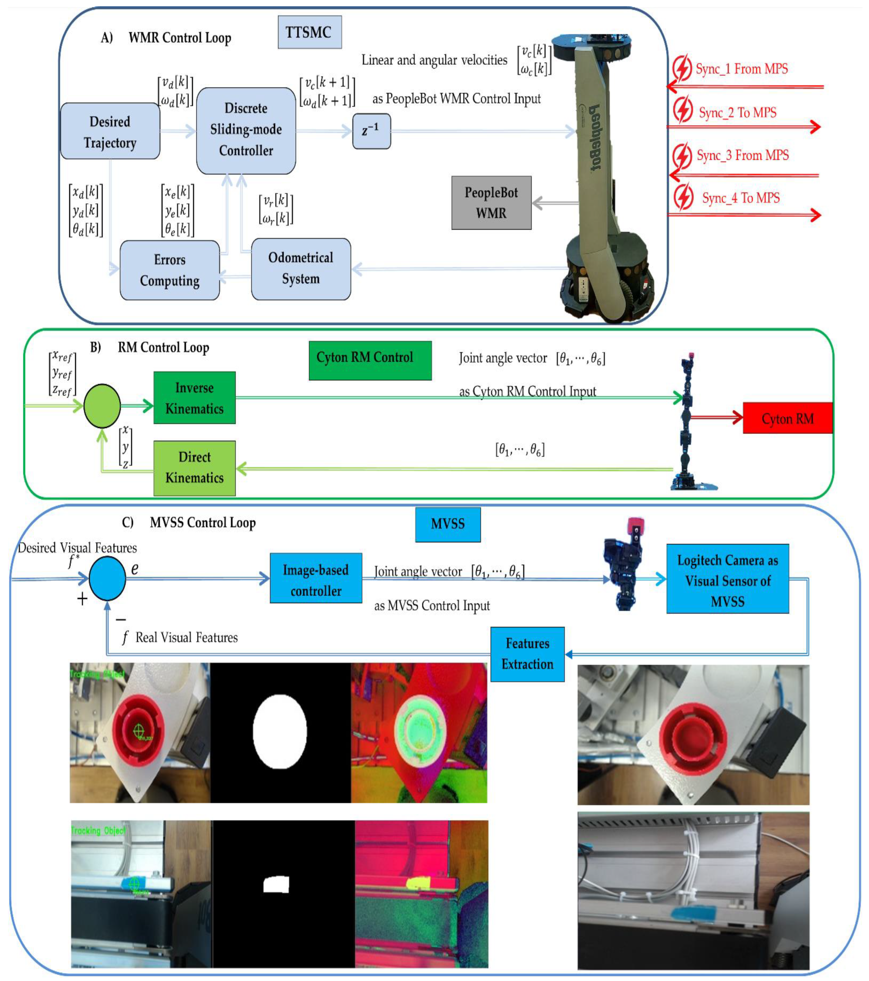
The control system for the MCPRS utilizes three hierarchical control loops that ensure the effective functioning of its key components: PeopleBot WMR, Cyton RM, and MVSS, shown in Figure 17. These loops coordinate tasks like transportation, manipulation, and visual guidance in real-time through a combination of local and remote interactions with PC-HMIs-dashboards and SCADA system.
A). The first control loop (PeopleBot WMR control) controls the movement of the PeopleBot WMR for forward and backward motion between WS4 and WS1. The control method is DT-TTSMC. Ensures precise trajectory tracking under dynamic conditions. Integrates real-time data from the robot’s odometer system and an onboard. Communication uses ARIA Mobile Robots Library for command execution. Communicates wirelessly with the remote or local PC-HMI via the SCADA system. Position and feedback data are transmitted from the embedded microcontroller via Wi-Fi to the SCADA server, which computes and sends control commands back to the WMR.
B). The second Control Loop (Cyton RM command synchronization). Handles the synchronization of commands between the Siemens S7-1200 PLC, and the Cyton RM. Control method is Modbus TCP communication that uses standard industrial protocols for real-time coordination between PLCs and the Cyton RM. This control loop ensures smooth task execution for robotic arm manipulation. Commands are wirelessly transmitted between the PC-HMI -MCPRS and the Cyton RM through an Ethernet adapter using a specific TCP/IP protocol.
C). Third control loop (MVSS control for end-effector accuracy) controls the movement of the MVSS to enhance the accuracy of pick-and-place tasks performed by Cyton RM’s end- effector. The control method is an image moments method and processes real-time image data to guide the end-effector for precise positioning. This control uses wireless communication to interface between the PC-HMI-MCPRS and MVSS. The communication is based on real-time updates sent wirelessly to adjust the positioning dynamically.
The role of SCADA and HM-MCPRS in coordination consists of the PC-HMI -MCPRS functioning as a SCADA server to synchronize data from all three control loops, to coordinate between the PeopleBot WMR, Cyton RM, and MVSS and transmit commands wirelessly to the MPS’s Siemens S7-300 PLCs for integration with WSs activities. SCADA extends monitoring and control to remote locations via cloud-based VPN connections, facilitating real-time decision-making and supervisory tasks.
Cyber-physical integration of MCPRS consists of a combination between physical elements, WMR, RM, MVSS, and computational processes, SCADA, HMIs, and wireless communication. IoT-like features share basic IoT architecture, with a seamless interface between computational and physical layers, and leverage real-time feedback from embedded systems for adaptive control.
Advantages of this real-time control architecture are the following: Precision by DT-TTSMC that ensures accurate trajectory tracking and smooth operation. Flexibility: by wireless communication and modular control loops allow rapid adjustments to dynamic workflows. Scalability by the integration of SCADA and IoT protocols that supports scaling for more complex systems. User-friendly monitoring by HMI-MCPRS offers intuitive interfaces for local and remote users to monitor and control system operations effectively.
4.3. Real-Time Control of MPS Assisted by MCPRS
The real-time control of the Modular Production System (MPS), assisted by the MCPRS), relies on advanced perception, computation, and actuation strategies to achieve precise picking, placing, and transporting tasks. This integration of robotic manipulation and mobile vision-based control ensures high reliability for P/R/S) operations. The assisting P/R/S technology for MPS consists of one dynamic robotic system: MCPRS used in picking, placing, and transporting the WP. Based on the inverse kinematic control, the remote PC-HMI-MCPRS calculates the order for the Cyton 1500 RM for parking and positioning related to pick-up and rough plating operations. Based on the method of moments of the image, the remote PC-HMI-MCPRS calculates the command for fine positioning the end-effector of the Cyton RM for picking and placing the WP.
- Picking operations, detection and precision control: The remote or local PC-HMI-MCPRS calculates positioning commands for the Cyton 1500 robotic manipulator (RM). These commands guide the RM for initial positioning for pickup operations at WS4. In Figure 18, the MVSS steps for WP detection are shown when taking over from WS4. On the upper left side in Figure 18 is vision-based detection by MVSS. Detection utilizes RGB-to-HSV color model conversion for robustness under varying lighting conditions. HSV better handles light changes compared to RGB, crucial during transitions between natural and artificial lighting. Object shape and position are determined using Ramer-Douglas-Peucker algorithm that simplifies the object contour for shape analysis. Canny Edge Detection identifies the edges of the object for precise contouring. Centroid tracking employs the method of image moments, ensuring efficient 2D tracking. The process is robust for circular objects, consistently identifying their centroid within acceptable error limits. All of this was implemented using the OpenCV libraries, [37]. Finally, in the image on the top right of the medallion in Figure 18, the object is tracked, meaning the target has been identified, if both the color and shape conditions were simultaneously met, [13].
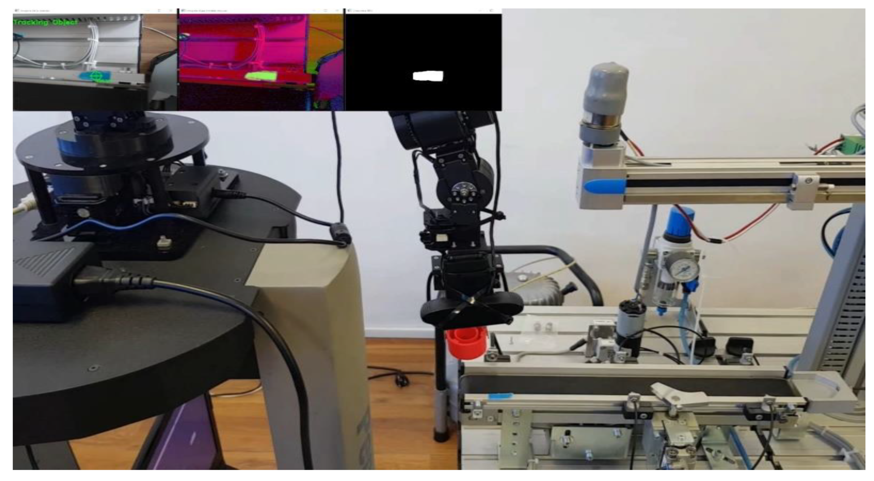
- Vision-based detection, alignment reference point and placing operations: On the upper left side in Figure 19 is: WS1 detection and alignment reference point detection. The WS1 placement relies on detecting a rectangular reference point, contrasting the circular object detection at WS4. This step ensures accurate alignment for reprocessing or scrapping. Fine Positioning with MVSS: like positional refinement is based on real-time feedback from MVSS. Adjustments in end-effector positioning minimize error before placement.
Figure 18.
MVSS-based Cyton RM control for WP’s picking up from WS4. In the top left medallion is WP’s detection with the following steps: conversion from RGB to HSV; image segmentation after the color has been found between the HSV limits and the shape corresponding to object has been found; object color and shape has been found and is being tracked.
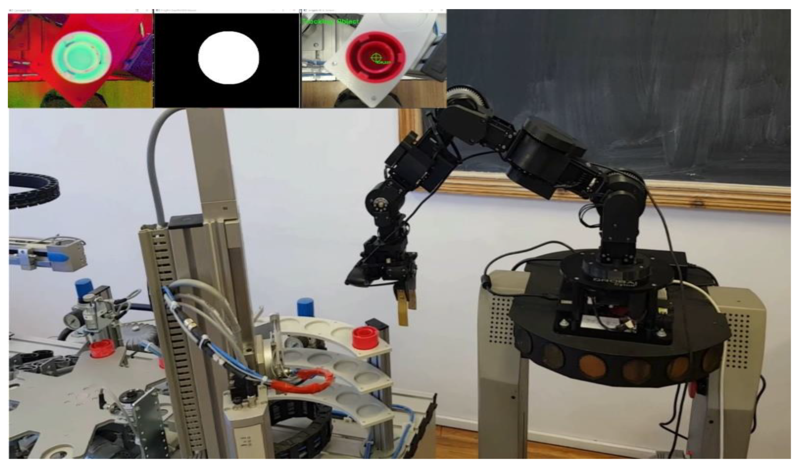
Figure 19.
MVSS-based Cyton RM for WP’s placing on WS1. In the top left medallion is reference point detection with the following steps: conversion from RGB to HSV; image segmentation after the color has been found between the HSV limits and the shape corresponding to reference has been found; reference object color and shape has been found and is being tracked.
Fine positioning with MVSS means positional refinement based on real-time feedback from MVSS for WP piking, and adjustments in end-effector positioning minimize error before placement, for WP placing.
Trajectory precision concerns how real-time visual feedback corrects deviations. This was evident in Figure 22(a) and Figure 22(b), where adjustments occur dynamically over time.
The integration of inverse kinematics, real-time vision-based control, and synchronized trajectory planning makes MPS-MCPRS operations efficient and precise. Continuous improvements in vision algorithms, lighting adaptability, and trajectory correction mechanisms can further enhance reliability and cycle times.
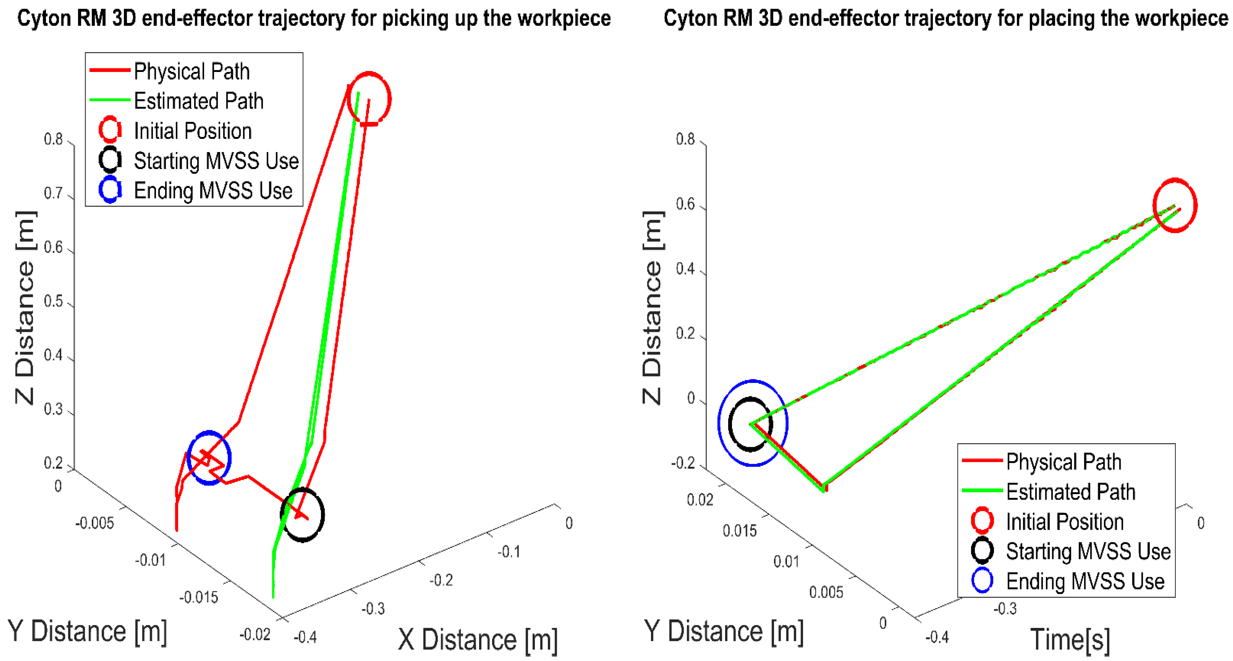
Trajectory optimization means 3D trajectory planning. Figure 20(a) presents the full trajectory for picking tasks: home, scanning, above object, picking, return to home. Figure 20(b) demonstrates a similar trajectory for placement tasks. Deviations when picking the workpiece is along the Y-axis deviation peaks at 10 mm but stabilizes. Placing: Reduced deviation due to tighter control of alignment.
Figure 20.
Estimated (desired) and physical (real) 3D trajectories of Cyton RM for: (a) WP’s picking from WS4; (b) WP’s placing on WS1.
Figure 20.
Estimated (desired) and physical (real) 3D trajectories of Cyton RM for: (a) WP’s picking from WS4; (b) WP’s placing on WS1.
Efficiency analysis concerns cycling time for piking operation tasks, over 10 seconds, Figure 21(a) and (b) while for placing operations is around 8 seconds, Figure 22(a), and (b). Time differences decrease from higher deviations during picking due to initial alignment challenges.
Trajectory precision concerns how real-time visual feedback corrects deviations. This was evident in Figure 22(a) and Figure 22(b), where adjustments occur dynamically over time.
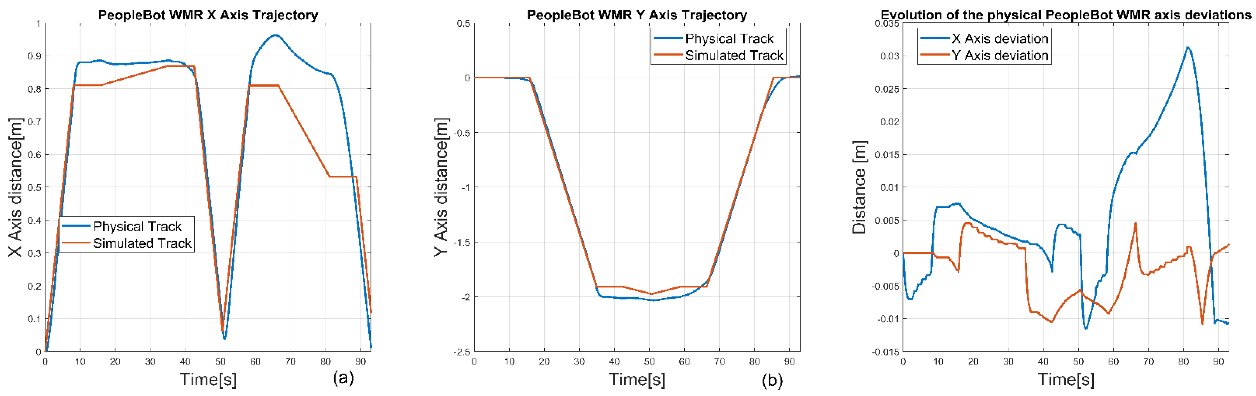
Transport operations PeopleBot WMR control is based on DT-TTSMC, to whom trajectories are controlled using DT-TTSMC (Digital Twin-Time Trajectory Sliding Mode Control). Position feedback ensures real-time adjustments to minimize errors with the following performance:
Errors observed in MCPRS trajectory along x X-axis is 30 mm, (Figure 23 (a) and (c)), along Y-axis: is over 5mm (Figure 23 (b) and (c), indicating high alignment accuracy during transport.
The integration of inverse kinematics, real-time vision-based control, and synchronized trajectory planning makes MPS-MCPRS operations efficient and precise. Continuous improvements in vision algorithms, lighting adaptability, and trajectory correction mechanisms can further enhance reliability and cycle times.
Figure 21.
Simulated and physical real trajectories evolution over time for (a) X and Z axis and (b) Y axis for picking the workpiece.
Figure 21.
Simulated and physical real trajectories evolution over time for (a) X and Z axis and (b) Y axis for picking the workpiece.
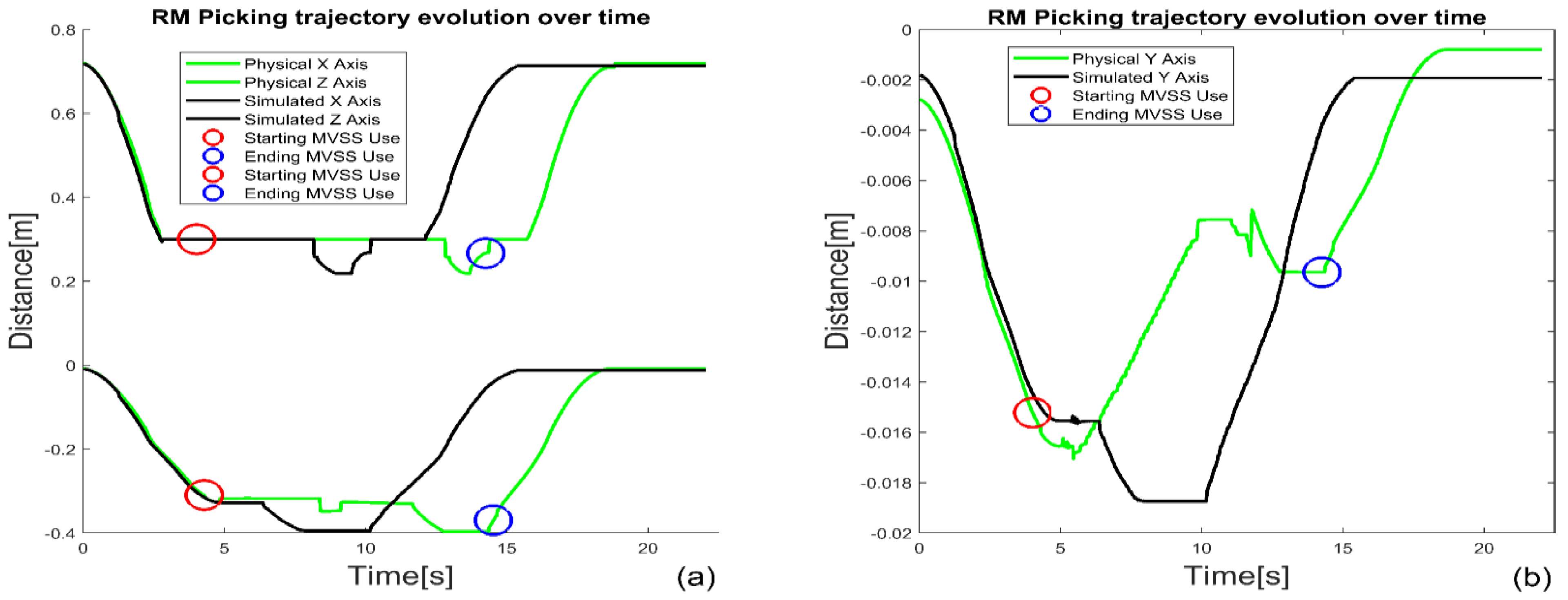
Figure 22.
Simulated and physical (real trajectories evolution over time for (a) X and Z axis and (b) Y axis in the case of picking the workpiece.
Figure 22.
Simulated and physical (real trajectories evolution over time for (a) X and Z axis and (b) Y axis in the case of picking the workpiece.
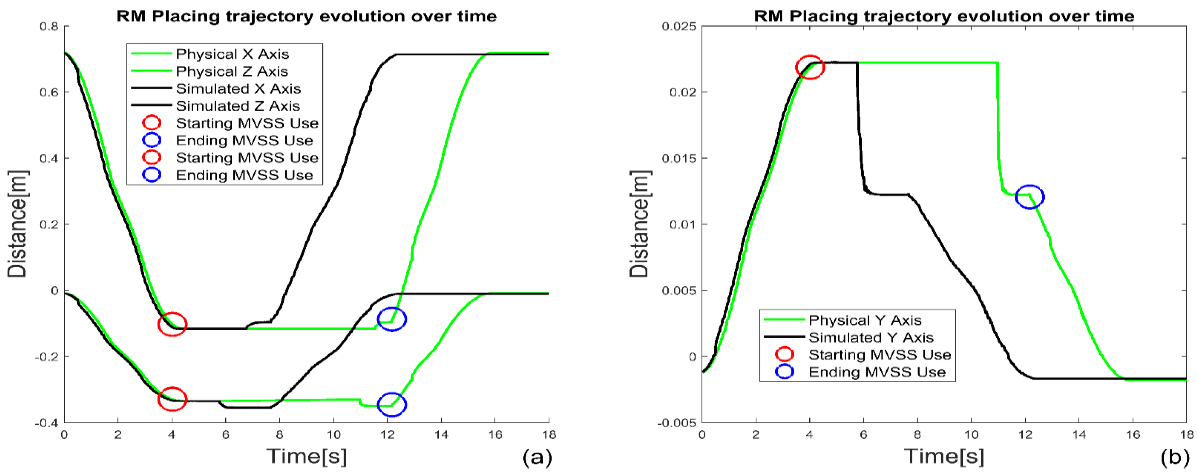
Figure 23.
MCPRS’s real-time and simulated in MobileSim trajectories; (a) along X-axis, (b) along Y-axis, (c) MCPRS’s X and Y tracking errors.
Figure 23.
MCPRS’s real-time and simulated in MobileSim trajectories; (a) along X-axis, (b) along Y-axis, (c) MCPRS’s X and Y tracking errors.
5. Discussion
A comprehensive system architecture for the Cloud/VPN-based remote control of MPS (four-workstation modular production system) assisted by a MCPRS is presented. The remote control of the described system integrates advanced IoT, Cloud, and VPN technologies with hierarchical automation for seamless operation and monitoring. It enables users to interact with, control, and optimize the production and handling tasks remotely through a robust framework.
The benefits of approaching such a production system are the following:
- Remote control and flexibility through the Cloud/VPN system. Users can control MPS and MCPRS by AR interfaces for task management. The VPN ensures secure access, while OPC-UA facilitates data sharing with cloud platform.
- Enhanced workflow optimization by using SHPN simulation allows for systematic modelling of both continuous and discrete processes, helping to optimize task execution and prevent bottlenecks in the system.
- Advanced communication infrastructure by using Profibus DP, Profinet, Ethernet, and OPC-UA ensures real-time, reliable communication across the system, with seamless integration between the production line, robotic systems, and cloud.
- Interoperability and future scalability with OPC-UA, LAN-Profinet, and LAN Ethernet, the system is future-proof, allowing for easy integration of additional devices, sensors, or workstations as needed.
- Real-time task planning and visualization by planning tasks, simulating workflows, and visualizing the system in real-time through AR and VR interfaces, enabling quick decisions and optimizations.
- Enhanced flexibility by using SHPN, TPN and CPN, models allowing for flexible task execution, supporting both discrete (stationary WSs) and continuous (MCPRS) operations.
- Fault detection and reprocessing with MCPRS assisting in reprocessing defective WPs, reducing downtime and improving overall production efficiency. Visual feedback through MVSS allows the MCPRS to autonomously handle quality control tasks.
- Cloud-based control through OPC-UA and WAN-Ethernet, the system can be monitored and controlled remotely, offering cloud-based SCADA/HMI interfaces for enhanced accessibility and control from any location.
To assess the effectiveness of a Cloud/VPN-based remote-control system for MPS assisted by MCPRS utilizing DT approach, a systematic evaluation strategy is required. This strategy must consider performance, functionality, reliability, and user satisfaction. Below are the methods for evaluation:
- Measure the percentage of tasks successfully completed without interruptions or errors, such as processing, reprocessing, and scrapping workflows. Evaluate the synchronization between the MPS and MCPRS. Use metrics like delay in command execution or deviations between DT simulations and real-world actions.
- Test the latency of the Cloud/VPN connection, particularly for critical operations requiring real-time feedback (task planning with AR or reprocessing tasks). Monitor the availability of the system components, (PLCs, embedded computer, MCPRS, WSs and DT) under varying operational loads. Measure the number of WPs processed, reprocessed, or scrapped per unit of time.
- Simulate scenarios with varying task complexities and multiple users remotely access the system to test scalability. Evaluate how well the system adapts to changes in production requirements, including the addition of new tasks or equipment.
- Conduct surveys or interviews with remote and local users to understand their experience with AR-based task planning and VR visualizations. Evaluate HMIs in terms of intuitiveness, error rates, and ease of navigation. Measure the time required for new users to learn and operate the system efficiently.
- Count system failures, communication errors, or downtime incidents over a defined period. Conduct penetration testing to evaluate the resilience of the Cloud/VPN infrastructure against cyber threats.
- Compare the DT simulation outcomes with real-world results. Metrics include deviation in task execution times or movements of the MCPRS. Assess the accuracy and usefulness of AI (machine learning)-based maintenance alerts or process optimizations
- Monitor the energy efficiency of the MPS and MCPRS during operations. Calculate the costs associated with remote operations and compare them to traditional on-site methods.
- Use SHPNs to simulate different production scenarios and validate system responses. Leverage SCADA systems to display and analyze key performance indicators in real time. Compare the system's performance against industry standards or similar setups.
Designing HMIs for the Cloud/VPN-based remote control of a MPS assisted by a MCPRS with a DT approach demands careful consideration of user experience, usability, and user feedback mechanisms to ensure effective operation in Industry 4.0 and 5.0 environments, by the following:
- Ensure HMIs provide intuitive, real-time visual feedback about the status of the MPS and MCPRS (WP location, task progress, errors). Include 3D models and AR/VR representations linked to the DT to visualize task planning and execution interactively. Implement customizable dashboards, allowing users to tailor views based on their roles. Use touch-based or voice-controlled interfaces for ease of operation, especially for mobile or wearable devices. Maintain consistency in layout, color schemes, and symbols across various control panels for different systems (MCPRS control vs. MPS task planning). Follow established user interface design guidelines, such as those from ISO standards for industrial interfaces. Include built-in mechanisms for guiding users to avoid common errors (confirmations for critical actions, visual warnings for system constraints). Provide contextual troubleshooting suggestions based on detected issues. Provide contextual troubleshooting suggestions based on detected issues.
- Design hierarchical menus logically, ensuring quick access to critical functions such as emergency stops or manual overrides. Enable multi-layer zoom for detailed and high-level views of the entire MPS and MCPRS workflows. Use automated task suggestions and assistive AI tools to streamline repetitive or complex operations. Offer drag-and-drop task scheduling in AR/VR environments for task planning. Provide auditory, haptic, or visual feedback to confirm actions, such as successful execution of reprocessing and scrapping command or MCPRS movement. Ensure HMIs are accessible to diverse users, including features like multilingual support, adjustable text sizes, and high-contrast modes.
- Include in-app feedback forms or direct links to reporting issues or requesting new features. Implement a feedback loop where operators receive responses to their suggestions or concerns. Track user interaction metrics, average task time, and error rates to identify usability bottlenecks. Regularly test HMIs with end-users during design and after deployment.
- Enable users to manipulate 3D models in AR to visualize and modify workflows dynamically. Allow operators to walk through virtual environments to practice controlling MPS and MCPRS workflows or diagnose issues remotely.
- Log errors to identify areas where HMIs complexity may lead to mistakes. Adjust workflows to be more user-friendly based on error patterns. Provide interactive tutorials or simulation-based training directly within HMIs, utilizing DT visualizations. Regularly assess how new operators adapt to the system and refine features to reduce the learning curve.
To examine potential cybersecurity threats and mitigation techniques for MPS assisted by MCPRS with DT approach, it's essential to identify and assess risks associated with each layer of the system and implement robust countermeasures.
- Unauthorized access to sensitive production data stored in the cloud. VPN vulnerabilities, such as default configurations or weak encryption, leading to eavesdropping or unauthorized access. Overwhelming the cloud service with traffic to disrupt operations. Attackers gain higher access levels in the cloud environment. Conduct regular vulnerability scans and penetration tests on the VPN and cloud systems.
- Intercepting data between physical and virtual digital twins. Introducing false data to the DT for incorrect task planning or decision-making. Modifying task planning or simulations in AR/VR. Monitor the consistency between physical and virtual digital twins with hash-based verification. Use real-time validation for AR/VR interactions to prevent discrepancies.
- Intercepting traffic on OPC UA or Profinet and Ethernet networks. Re-sending valid commands to disrupt synchronized operations. Encrypting MPS control data to halt operations. Deploy intrusion detection systems for LAN/WAN traffic. Conduct protocol fuzzing for OPC UA and Profinet to identify weaknesses.
- Exploiting interfaces to control MCPRS movements or manipulations. Tampering with MVSS inputs to misdirect MCPRS operations. Targeting vulnerabilities in WMR or RM software. Validate commands with digital signatures. Use redundant sensor fusion to detect anomalies in localization.
- Enforce end-to-end encryption data transmission. Implement multi-factor authentication for cloud and VPN access. Use zero-trust architecture for access control, ensuring only verified users/devices can connect. Regularly apply security patches to cloud platforms and VPN clients.
- Use encrypted data streams between physical and digital twins. Deploy blockchain for immutable record-keeping of DT transactions. Implement role-based access control for AR/VR task planning. Use AI anomaly detection to identify malicious activity in DT simulations.
- Secure RM and WMR firmware with secure boot mechanisms. Introduce runtime integrity checks for MCPRS operations. Use geofencing policies to limit MCPRS operation to specific areas.
- Develop and enforce cybersecurity policies for employees and contractors. Deploy endpoint detection and response tools across WSs and PLCs. Establish an incident response plan and perform regular cybersecurity drills.
- To ensure the implemented cybersecurity measures are effective. Conduct periodic audits and risk assessments. Use penetration testing and red teaming to simulate attacks. Track key performance indicators, such as the number of blocked intrusion attempts or time to detect/respond to threats. Regularly review and update the system against emerging threats.Bottom of Form
6. Conclusions
The outlined system represents a significant advancement in the integration of MPS with MCPRS, employing DT approach. The novelty and originality of the system can be evaluated by the following:
- The system uniquely combines a modular production line with a mobile robot capable of handling dynamic task reallocation, including transporting defective products back to the first station for reprocessing or scrapping. This improves efficiency and adaptability compared to static production lines.
- Each of the four workstations is managed by a dedicated PLC, all connected via Profibus DP to a central PLC. This hierarchical architecture ensures robust control of the MPS while supporting interoperability between multiple subsystems. Integration of LAN-Profinet, LAN-Ethernet, and WAN-Ethernet with OPC-UA connectivity allows for seamless communication between local and cloud-based systems, enabling remote control and monitoring.
- The system allows users to visualize and interact with production workflows in real-time using AR. This enhances operational insight and decision-making, offering an intuitive interface for task scheduling and error handling. Through SHPN, TPN and CPN, the system provides real-time visualization of both the MPS and MCPRS operations. This ensures precise synchronization and improved transparency. Using SHPN to integrate TPN for MPS processes and CPN for MCPRS movement is a novel approach. This enables seamless synchronization between stationary and mobile elements, improving the system’s response to changes in production demands. This hybrid modeling ensures real-time adaptability and flexibility in production line workflows, crucial for scenarios like reprocessing or scrapping defective items.
- The MCPRS includes a wheeled mobile robot (2DW/1FW) with a 7-DOF RM and an MVSS. This provides high precision in handling and transporting workpieces. Its ability to interact with the production line dynamically and respond to feedback from quality tests is a distinct innovation in Industry 4.0 applications. The MCPRS enables defective workpieces to be reintroduced into the production line or scrapped based on quality control feedback. This level of adaptability is rare in traditional production systems.
- Through WAN-Ethernet and OPC-UA, the system supports cloud-based monitoring and VPN-enabled secure remote access. This is vital for real-time diagnostics, performance monitoring, and remote control. Enables decentralized control, supporting the scalability and resilience of the production process.
- The integration of AR, VR, and DT enhances automation, operational flexibility, and predictive capabilities. The system serves as a comprehensive teaching and research platform for advanced manufacturing systems, emphasizing real-time control, DT applications, and IoT-enabled connectivity.
The effectiveness of the Cloud/VPN-based remote control of an MPS and MCPRS can be systematically assessed by focusing on functional, performance, reliability, and user-centric metrics. Continuous monitoring and iterative improvement cycles, informed by collected data and feedback, ensure the system remains robust and aligned with Industry 4.0 and 5.0 objectives.
An effective HMIs design ensures seamless integration of Cloud/VPN-based remote control, DT visualizations, and MCPRS interactions, offering a balance of functionality and ease of use. Incorporating usability and user feedback mechanisms allows the system to evolve continuously, meeting the dynamic demands of Industry 4.0 and 5.0.
By integrating strategies for cybersecurity threats and mitigation techniques the Cloud/VPN-based remote-control system with DT technology can remain robust, resilient, sustainable and secure against a wide array of cybersecurity threats (demand of Industry 5.0).
Author Contributions
Conceptualization, all authors; methodology: A.F. (Adrian Filipescu), D.I., A.F. (Adriana Filipescu), and G.S.; software: G.S. and D.I.; validation: A.F. (Adrian Filipescu); formal analysis: G.S. D.I., and A.F. (Adriana Filipescu); writing—original draft preparation: A.F. (Adrian Filipescu), and A.F. (Adriana Filipescu); writing—review and editing: A.F. (Adrian Filipescu), A.F. (Adrian Filipescu); project administration: A.F. (Adrian Filipescu); funding acquisition, A.F. (Adrian Filipescu). All authors have read and agreed to the published version of the manuscript
Funding
This article (APC) will be supported by “Dunărea de Jos” University of Galati.
Institutional Review Board Statement
Not applicable.
Informed Consent Statement
Not applicable.
Data Availability Statement
Data availability is not applicable to this article as the study did not report any data.
Conflicts of Interest
The authors declare no conflicts of interest.
References
- Bradley, J.M.; Atkins, E.M. Optimization and Control of Cyber-Physical Vehicle Systems. Sensors 2015, 15, 23020–23049. [Google Scholar] [CrossRef]
- Mincă, E.; Filipescu, A.; Cernega, D.; Șolea, R.; Filipescu, A.; Ionescu, D.; Simion, G. Digital Twin for a Multifunctional Technology of Flexible Assembly on a Mechatronics Line with Integrated Robotic Systems and Mobile Visual Sensor—Challenges towards Industry 5.0. Sensors 2022, 22, 8153. [Google Scholar] [CrossRef]
- Simion, G.; Filipescu, A.; Ionescu, D.; Șolea, R.; Cernega, D.; Mincă, E.; Filipescu, A. Mobile Visual Servoing Based Control of a Complex Autonomous System Assisting a Manufacturing Technology on a Mechatronics Line. Inventions 2022, 7, 47. [Google Scholar] [CrossRef]
- Segovia, M.; Garcia-Alfaro, J. Design, Modeling and Implementation of Digital Twins. Sensors 2022, 22, 5396. [Google Scholar] [CrossRef] [PubMed]
- Moiceanu, G.; Paraschiv, G. Digital Twin and Smart Manufacturing in Industries: A Bibliometric Analysis with a Focus on Industry 4.0. Sensors 2022, 22, 1388. [Google Scholar] [CrossRef]
- Carlos-Mancilla, M.A.; Luque-Vega, L.F.; Guerrero-Osuna, H.A.; Ornelas-Vargas, G.; Aguilar-Molina, Y.; González-Jiménez, L.E. Educational Mechatronics and Internet of Things: A Case Study on Dynamic Systems Using MEIoT Weather Station. Sensors 2021, 21, 181. [Google Scholar] [CrossRef] [PubMed]
- Berriche, A.; Mhenni, F.; Mlika, A.; Choley, J.-Y. Towards Model Synchronization for Consistency Management of Mechatronic Systems. Appl. Sci. 2020, 10, 3577. [Google Scholar] [CrossRef]
- Adrian Filipescu, Eugenia Minca, Daniela Cernega, Razvan Solea, Adriana Filipescu, Simion Georgian, Dan Ionescu, Digital Twin Based a Processing Technology Assisted by a MCPRS, Ready for Industry 5.0, 97 - 3022023 27th International Conference on System Theory, Control and Computing, ICSTCC 2023Timisoara, 11-13 October 2023, ISSN: 2473-5698. [CrossRef]
- Filipescu, A.; Mincă, E.; Filipescu, A.; Coandă, H.-G. Manufacturing Technology on a Mechatronics Line Assisted by Autonomous Robotic Systems, Robotic Manipulators and Visual Servoing Systems. Actuators 2020, 9, 127. [Google Scholar] [CrossRef]
- Filipescu, Adrian; Minca, E. Filipescu, Adriana Mechatronics Manufacturing Line with Integrated Autonomous Robots and Visual Servoing Systems. In Proceedings of the 9th IEEE International Conference on Cybernetics and Intelligent Systems, and Robotics, Automation and Mechatronics (CIS-RAM 2019), Bangkok, Thailand, 18–20 November 2019; pp. 620–625. [CrossRef]
- Martinez, E.M.; Ponce, P.; Macias, I.; Molina, A. Automation Pyramid as Constructor for a Complete Digital Twin, Case Study: A Didactic Manufacturing System. Sensors 2021, 21, 4656. [Google Scholar] [CrossRef] [PubMed]
- Bamunuarachchi, D.; Georgakopoulos, D.; Banerjee, A.; Jayaraman, P.P. Digital Twins Supporting Efficient Digital Industrial Transformation. Sensors 2021, 21, 6829. [Google Scholar] [CrossRef] [PubMed]
- Vachálek, J.; Šišmišová, D.; Vašek, P.; Fiťka, I.; Slovák, J.; Šimovec, M. Design and Implementation of Universal Cyber-Physical Model for Testing Logistic Control Algorithms of Production Line’s Digital Twin by Using Color Sensor. Sensors 2021, 21, 1842. [Google Scholar] [CrossRef]
- Gallala, A.; Kumar, A.A.; Hichri, B.; Plapper, P. Digital Twin for Human–Robot Interactions by Means of Industry 4.0 Enabling Technologies. Sensors 2022, 22, 4950. [Google Scholar] [CrossRef] [PubMed]
- Stączek, P.; Pizoń, J.; Danilczuk, W.; Gola, A. A Digital Twin Approach for the Improvement of an Autonomous Mobile Robots (AMR’s) Operating Environment—A Case Study. Sensors 2021, 21, 7830. [Google Scholar] [CrossRef] [PubMed]
- Abdul Hadi, M.; Kraus, D.; Kajmakovic, A.; Suschnigg, J.; Guiza, O.; Gashi, M.; Sopidis, G.; Vukovic, M.; Milenkovic, K.; Haslgruebler, M.; et al. Towards Flexible and Cognitive Production—Addressing the Production Challenges. Appl. Sci. 2022, 12, 8696. [Google Scholar] [CrossRef]
- Angelopoulos, J.; Mourtzis, D. An Intelligent Product Service System for Adaptive Maintenance of Engineered-to-Order Manufacturing Equipment Assisted by Augmented Reality. Appl. Sci. 2022, 12, 5349. [Google Scholar] [CrossRef]
- Barczak, A.; Dembińska, I.; Marzantowicz, Ł. Analysis of the Risk Impact of Implementing Digital Innovations for Logistics Management. Processes 2019, 7, 815. [Google Scholar] [CrossRef]
- Fan, Y.; Lv, X.; Lin, J.; Ma, J.; Zhang, G.; Zhang, L. Autonomous Operation Method of Multi-DOF Robotic Arm Based on Binocular Vision. Appl. Sci. 2019, 9, 5294. [Google Scholar] [CrossRef]
- Ravankar, A.; Ravankar, A.A.; Kobayashi, Y.; Hoshino, Y.; Peng, C.-C. Path Smoothing Techniques in Robot Navigation: State-of-the-Art, Current and Future Challenges. Sensors 2018, 18, 3170. [Google Scholar] [CrossRef]
- Corke, P.I.; Spindler, F.; Chaumette, F. Combining Cartesian and polar coordinates in IBVS. In Proceedings of the 2009 IEEE/RSJ International Conference on Intelligent Robots and Systems, St. Louis, MO, USA, 11 December 2009; pp. 5962–5967. [Google Scholar]
- Copot, C. Control Techniques for Visual Servoing Systems. Ph.D. Thesis, Technical University of Iasi, Iasi, Romania, 2012. [Google Scholar]
- Petrea, G.; Filipescu, A.; Solea, R.; Filipescu, A., Jr/. Visual Servoing Systems Based Control of Complex Autonomous Systems Serving a P/RML. In Proceedings of the 22nd IEEE, International Conference on System Theory, Control and Computing, (ICSTCC), Sinaia, Romania, 10–12 October 2018; pp. 323–328. [Google Scholar]
- Song, R.; Li, F.; Fu, T.; Zhao, J. A Robotic Automatic Assembly System Based on Vision. Appl. Sci. 2020, 10, 1157. [Google Scholar] [CrossRef]
- Lan, C.-W.; Chang, C.-Y. Development of a Low Cost and Path-free Autonomous Patrol System Based on Stereo Vision System and Checking Flags. Appl. Sci. 2020, 10, 974. [Google Scholar] [CrossRef]
- Deng, L.; Wilson, W.; Janabi-Sharifi, F. Dynamic performance of the position-based visual servoing method in the Cartesian and image spaces. In Proceedings of the IEEE/RSJ International Conference on Intelligent Robots and Systems, Las Vegas, NV, USA, 27–31 October 2003; pp. 510–515. [Google Scholar]
- Gans, N.; Hutchinson, S.; Corke, P. Performance tests for visual servo control systems, with application to partitioned approaches to visual servo control. Int. J. Robot. Res. 2003, 22, 955–981. [Google Scholar] [CrossRef]
- Node-RED web-based flow editor for remote control, Node-RED 4.0 released - News - Node-RED Forum (nodered.org), (accessed on 11October 2024).
- Sirphyco Simulateur de Réseaux de Petri, Sirphyco-Simulateur-de-Reseaux-de-Petri. Available online: https://www.toucharger.com (accessed on 11 October 2024).
- MathWorks. Available online: https://www.mathworks.com (accessed on 11 October 2024).
- Totally Integrated Automation Portal, TIA Portal V17. Available online: https://www.siemens.com/tia-portal (accessed on 11 October 2024).
- OpenCV. Available online: https://opencv.org (accessed on 11 October 2024).
- Microsoft Visual Studio. Available online: https://www.visualstudio.com/vs/cplusplus (accessed on 11 October 2024).
- SCADA System SIMATIC, WinCC SIMATIC WinCC V7 / V8 - Siemens Xcelerator Global(accessed on 11 October 2024).
- VNC (Virtual Network Computing), RealVNC® Remote Access Software for Desktop and Mobile | RealVNC. Available online: https://www.realvnc.com (accessed on 11 October 2024).
- Advanced Robotics Interface for Applications (ARIA). Available online: https://web.archive.org/web/20180205212122/http://robots.mobilerobots.com/wiki/Aria (accessed on 11 October 2024).
- MobileSim, Simulator for Mobile Robots- http://robots.mobilerobots.com/MobileSim.
Figure 1.
Four-WSs-MPS 200 assisted by MCPRS, PeopleBot WMR equipped with Cyton 1500 RM and MVSS with Logitech camera.
Figure 1.
Four-WSs-MPS 200 assisted by MCPRS, PeopleBot WMR equipped with Cyton 1500 RM and MVSS with Logitech camera.
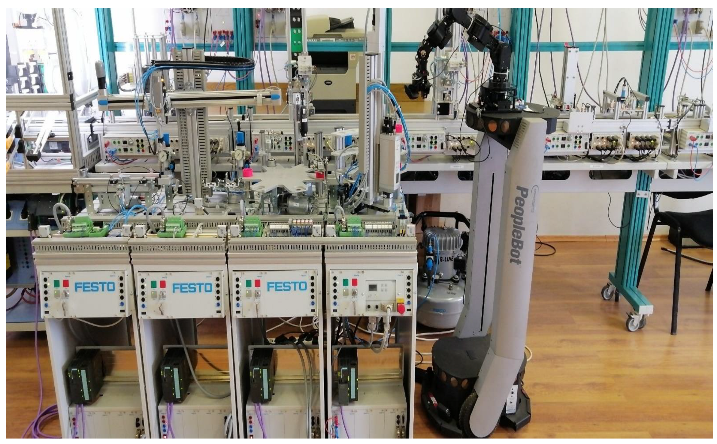
Figure 3.
Five levels architecture for remote or local control of MPS assisted by MCPRS.
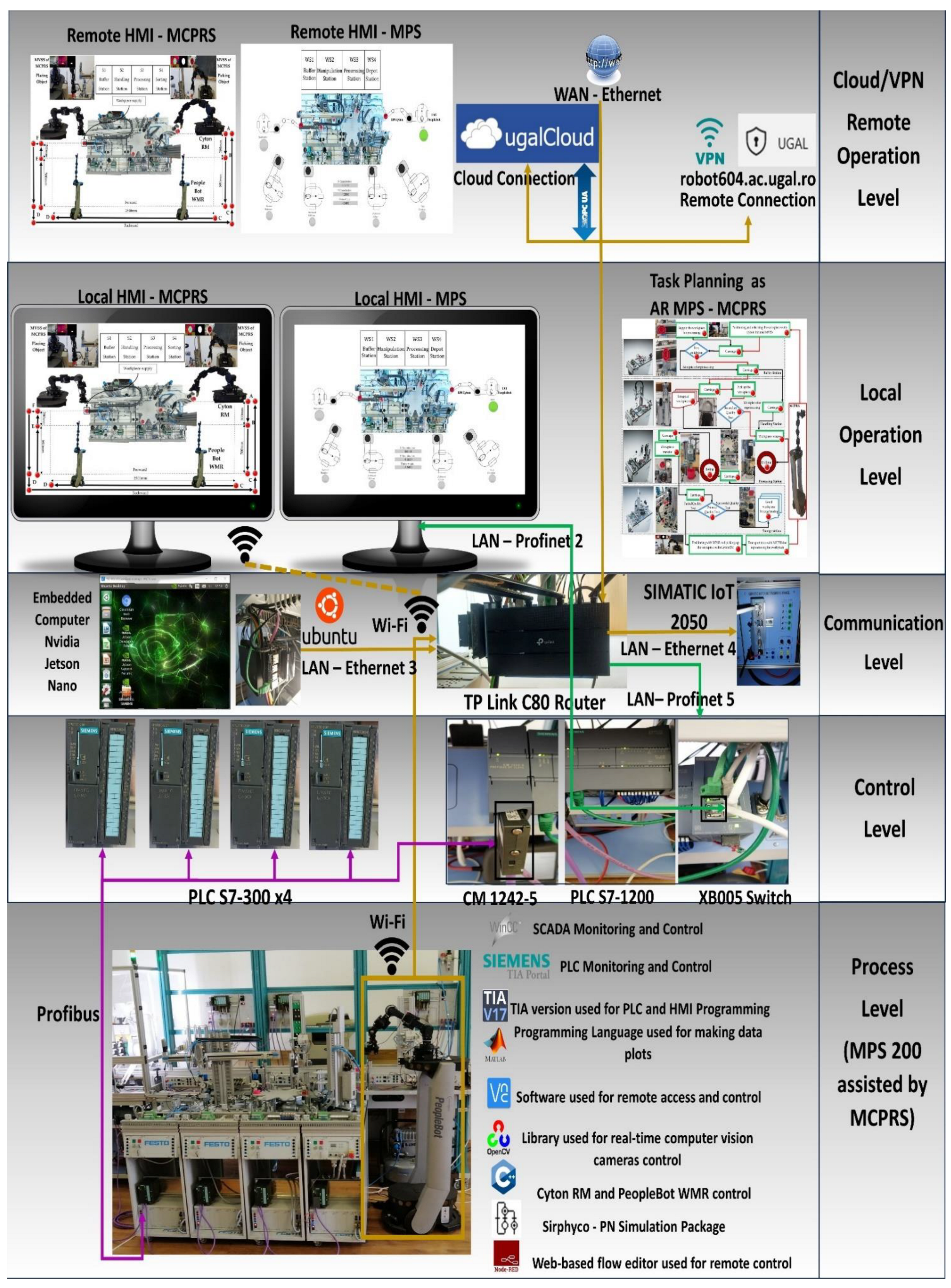
Figure 4.
WP along MPS's workstations, MCPRS's movements, WP's picking and placing by RM and MVSS.
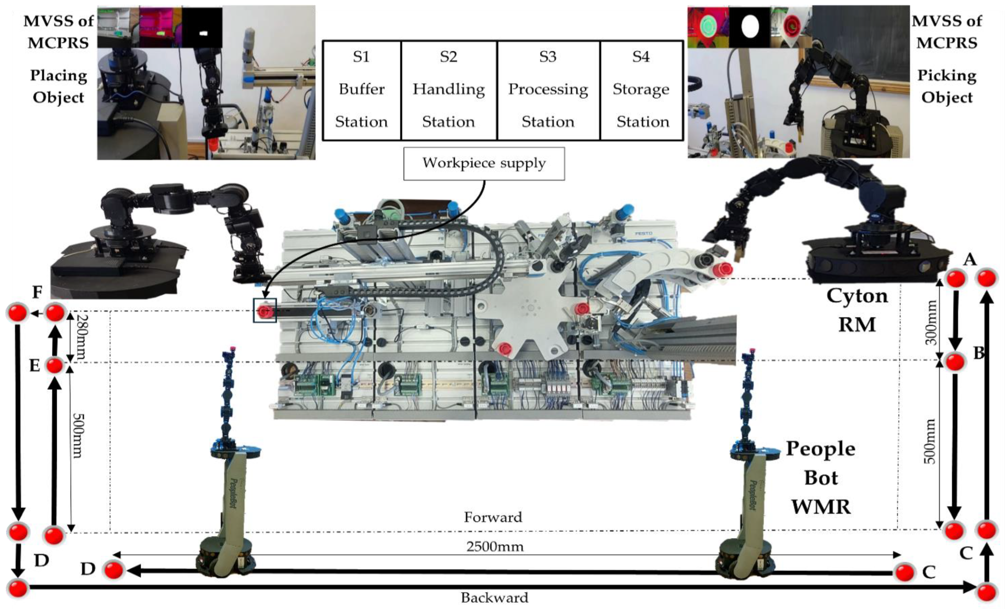
Figure 5.
Node-RED, P/R/S task planning augmented reality.
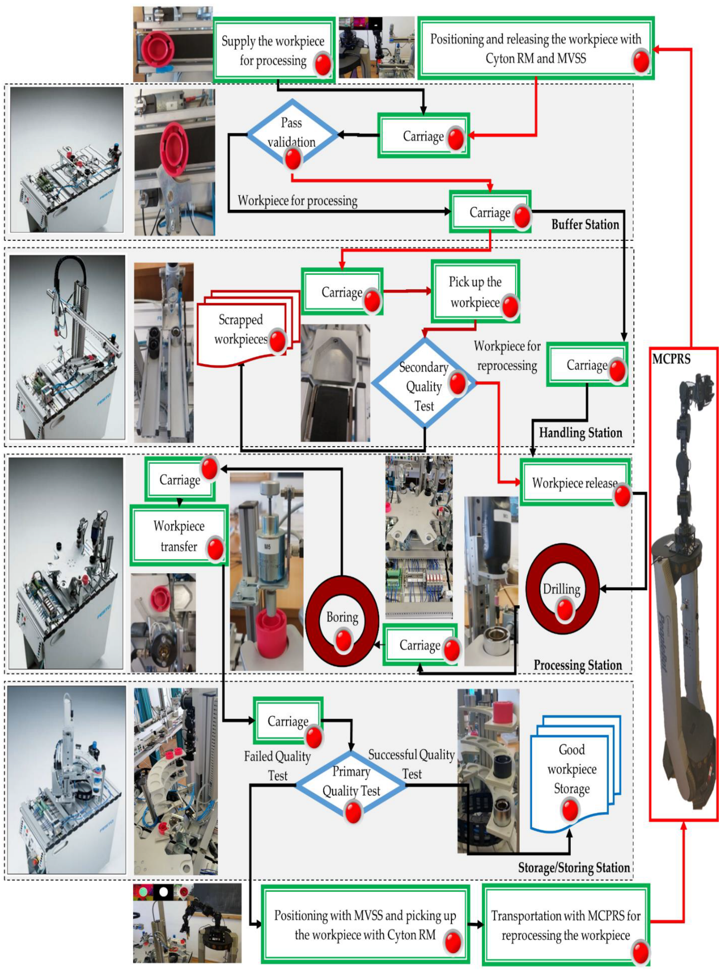
Figure 6.
Structure of SHPN model: TPN_1, TPN_2 and TPN_3 for P/R/S on MPS, CPN_1 and CPN_2 for MCPRS movements.
Figure 6.
Structure of SHPN model: TPN_1, TPN_2 and TPN_3 for P/R/S on MPS, CPN_1 and CPN_2 for MCPRS movements.
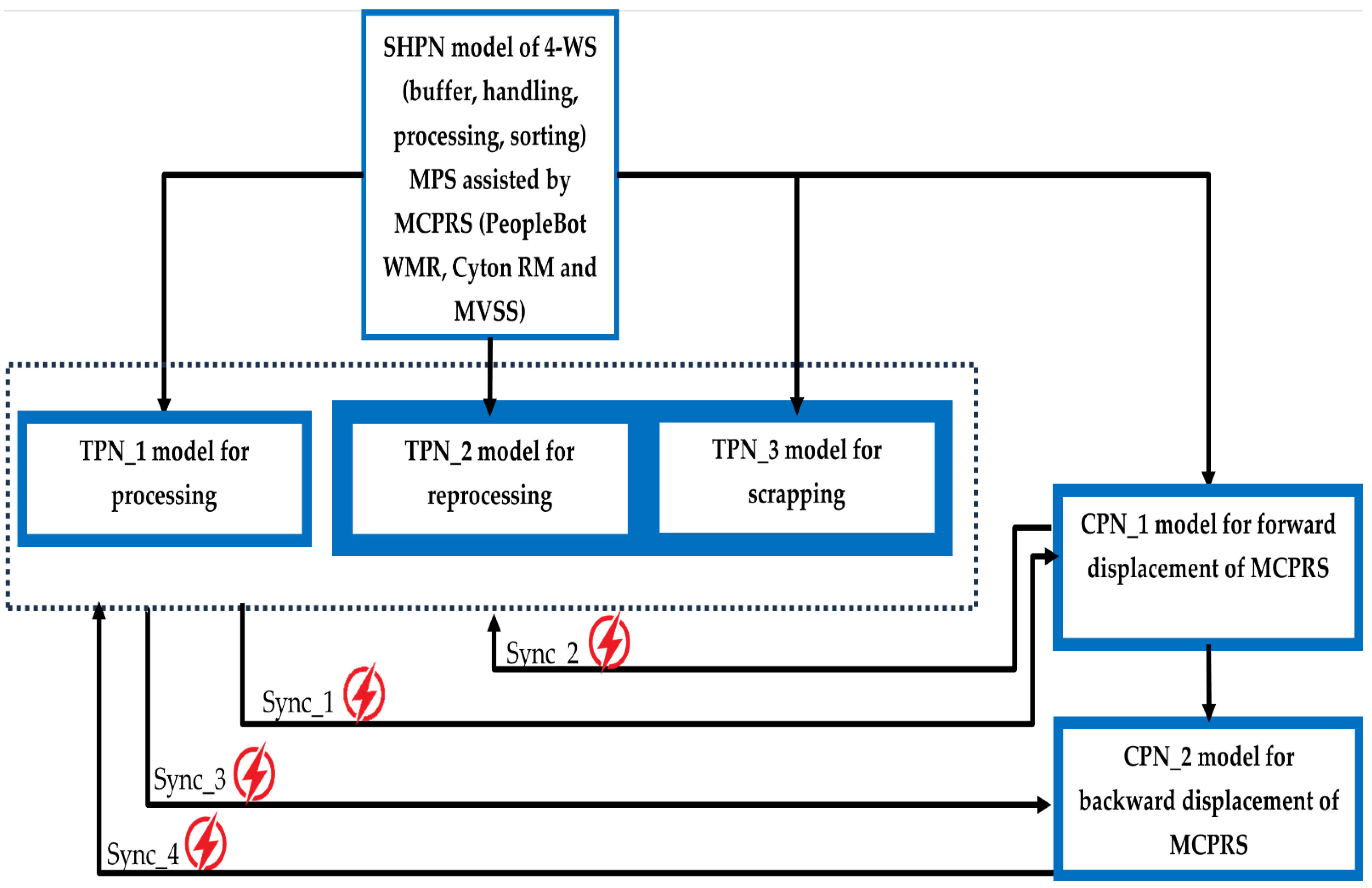
Figure 7.
SHPN model (TPN_1, TPN_2, TPN_3, CPN_1, CPN_2) of P/R/S operations on MPS assisted by MCPRS.
Figure 7.
SHPN model (TPN_1, TPN_2, TPN_3, CPN_1, CPN_2) of P/R/S operations on MPS assisted by MCPRS.
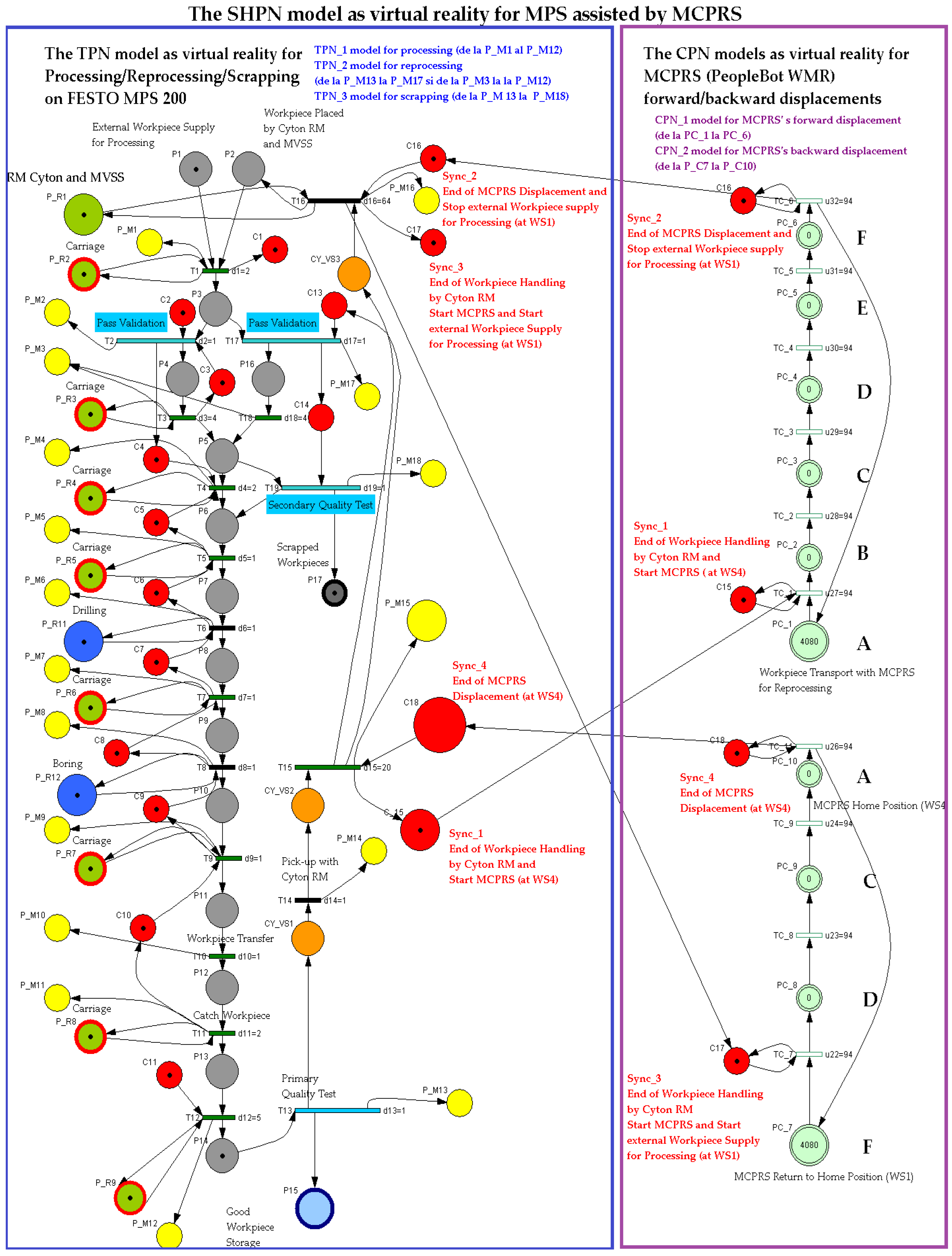
Figure 8.
Sirphyco simulation of the TPN_1 model for processing on MPS.
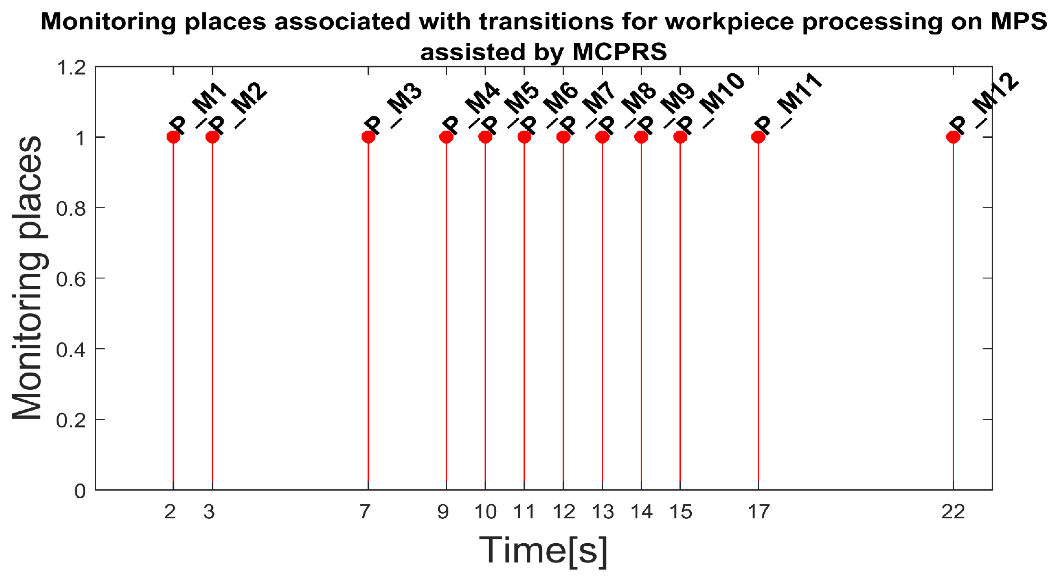
Figure 9.
Sirphyco simulation of the TPN_2 model for reprocessing on MPS.
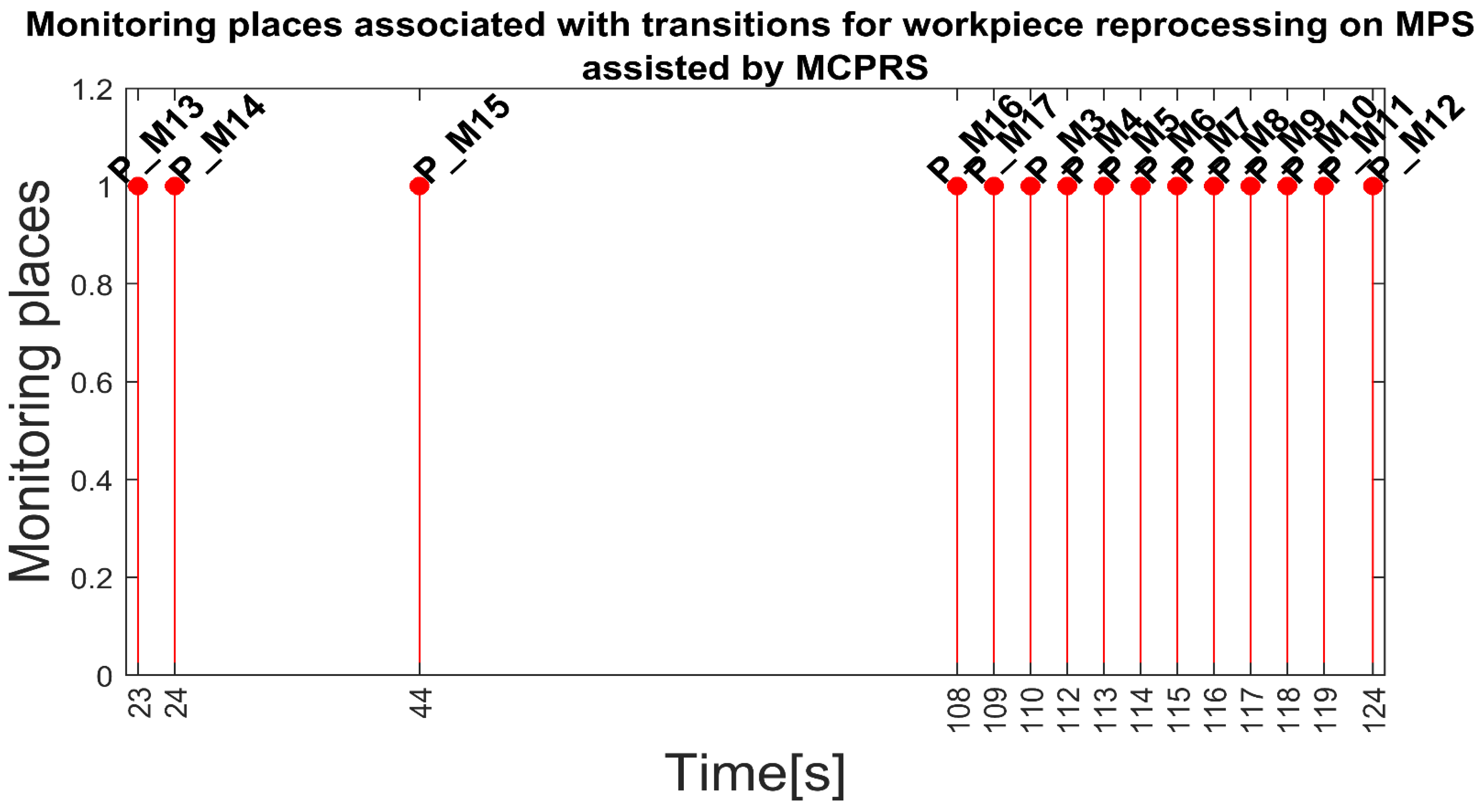
Figure 10.
Sirphyco simulation of the TPN_3 model for scrapping on MPS.
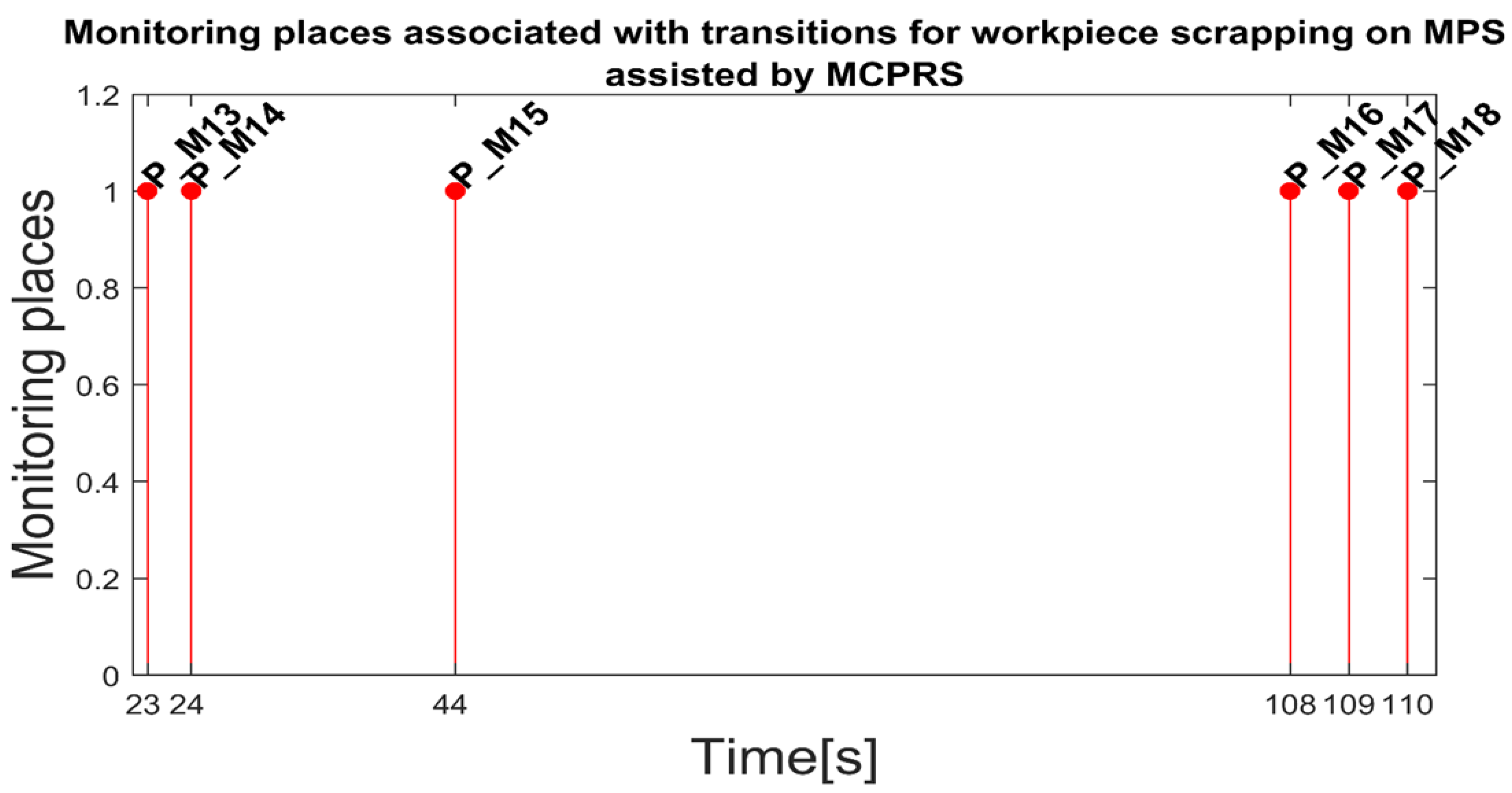
Figure 11.
Sirphyco simulation of CPN_1 and CPN_2 models for MCPRS forward and backward displacements.
Figure 11.
Sirphyco simulation of CPN_1 and CPN_2 models for MCPRS forward and backward displacements.
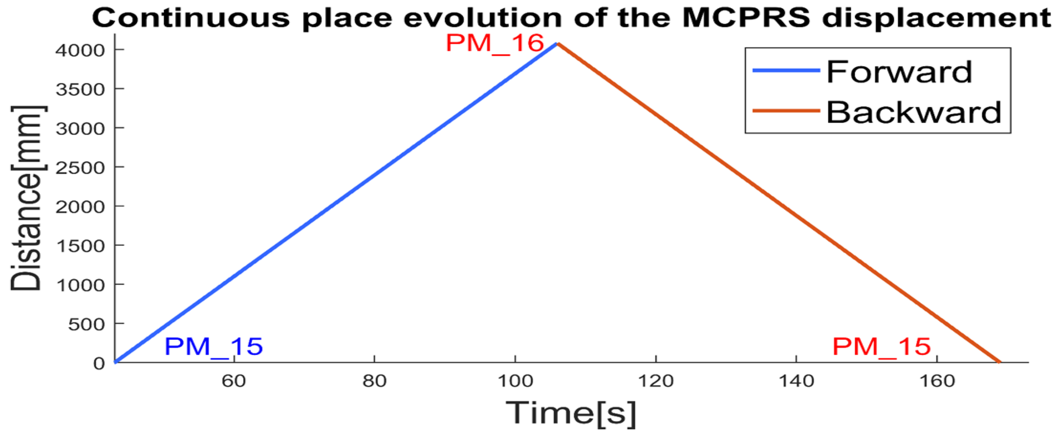
Figure 12.
MobileSim (a) forward and (b) backward trajectories of MCPRS around MPS.
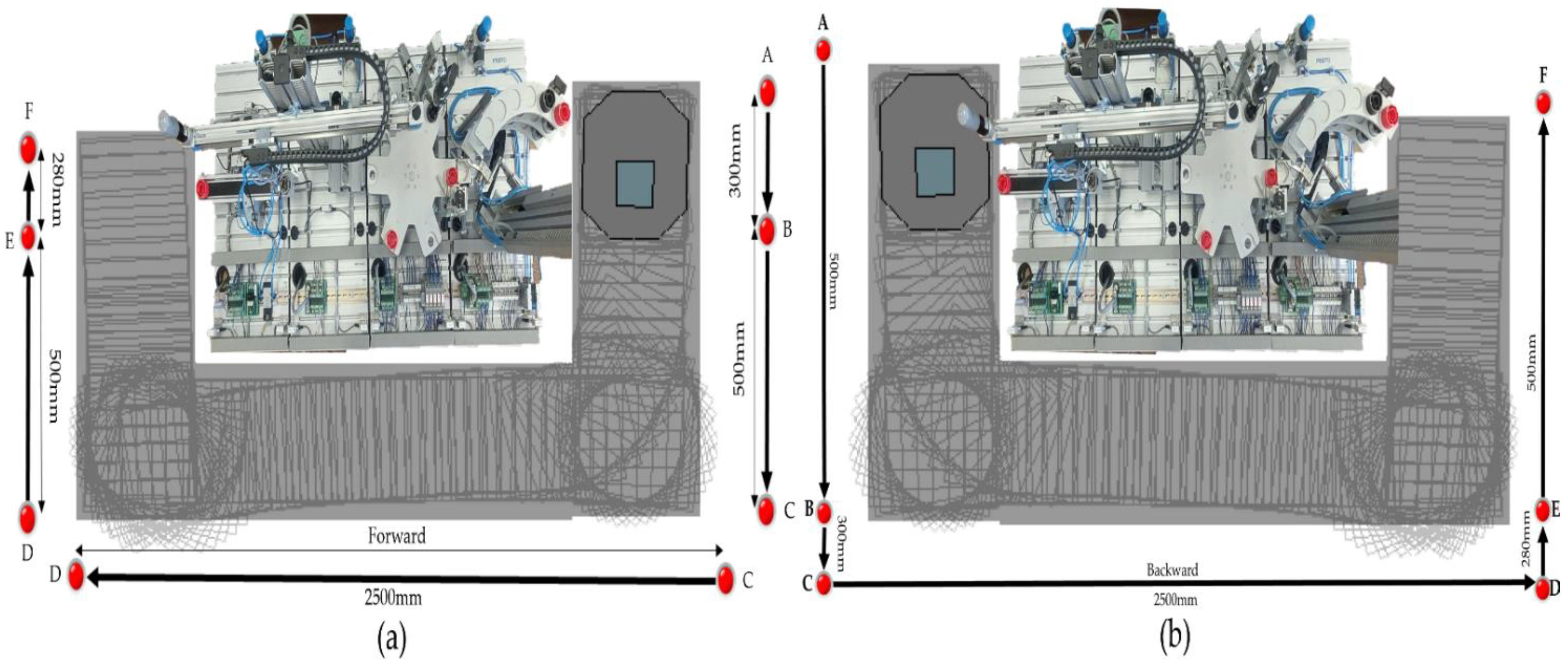
Figure 13.
Communication block set between MPS assisted by MCPRS and local PCs. HMI-MCPRS. and HMI-MPS.
Figure 13.
Communication block set between MPS assisted by MCPRS and local PCs. HMI-MCPRS. and HMI-MPS.
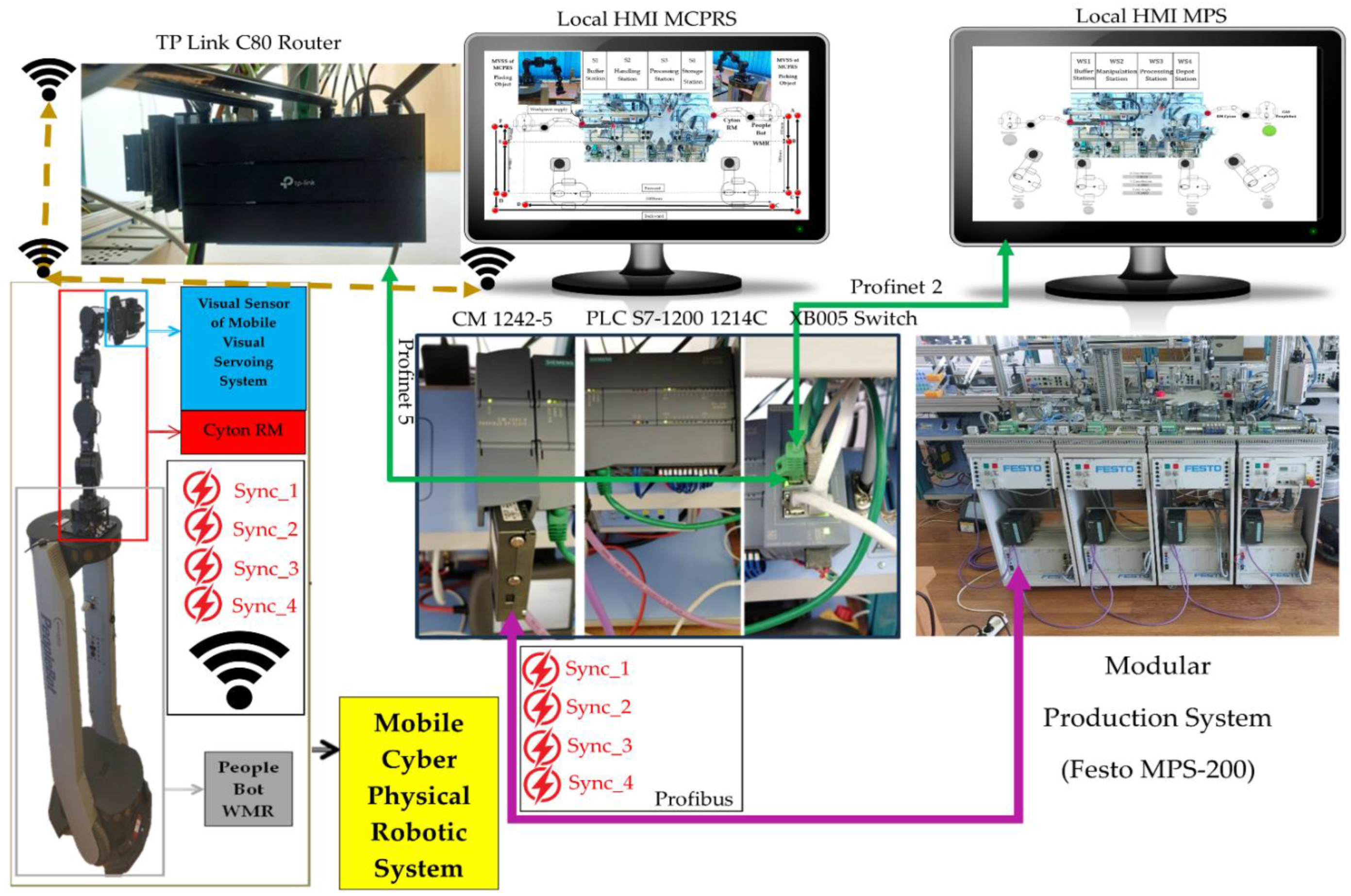
Figure 14.
Monitoring signals from master PLC for WP’s processing.
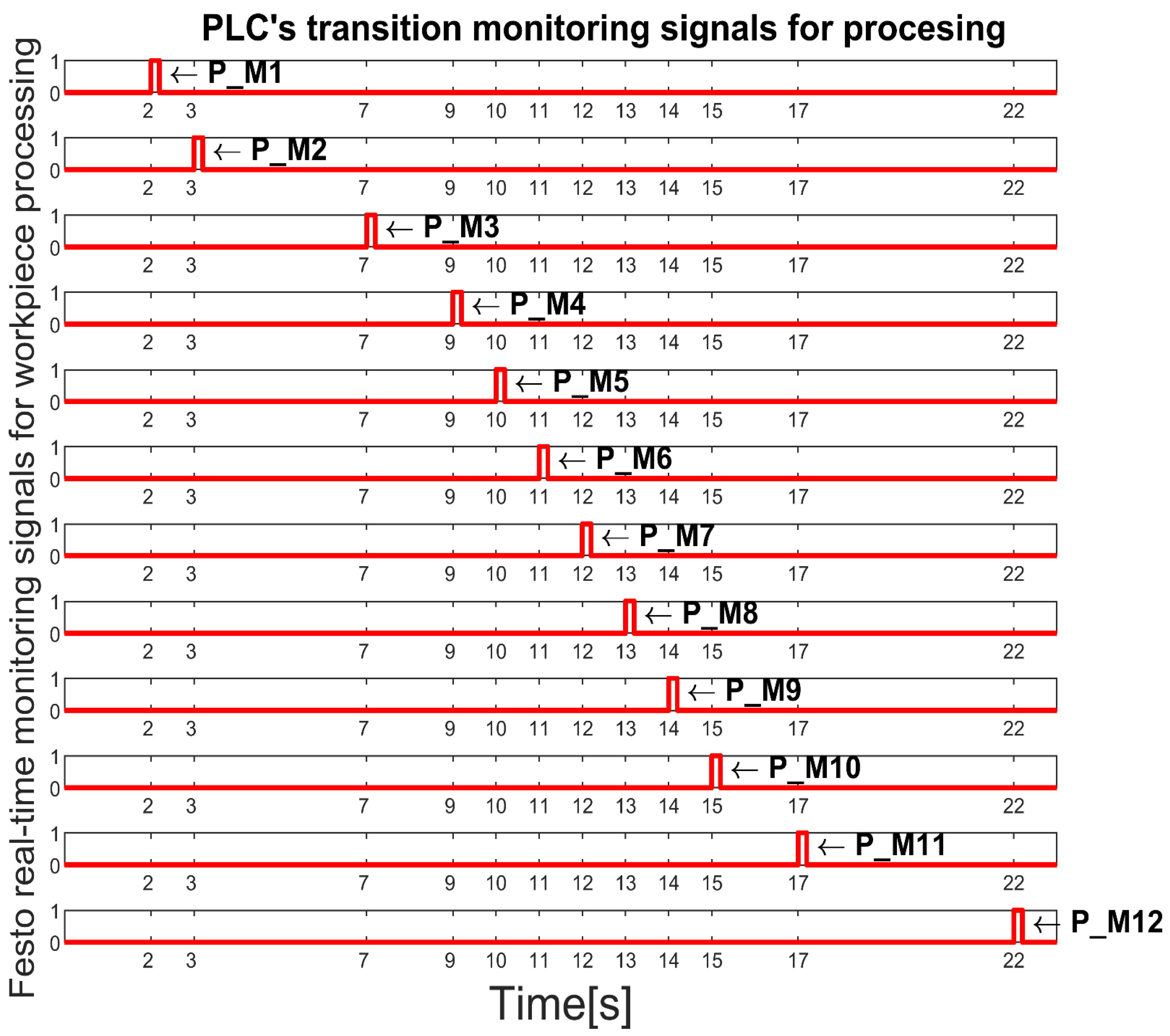
Figure 15.
Monitoring signals from master PLC for WP’s reprocessing.
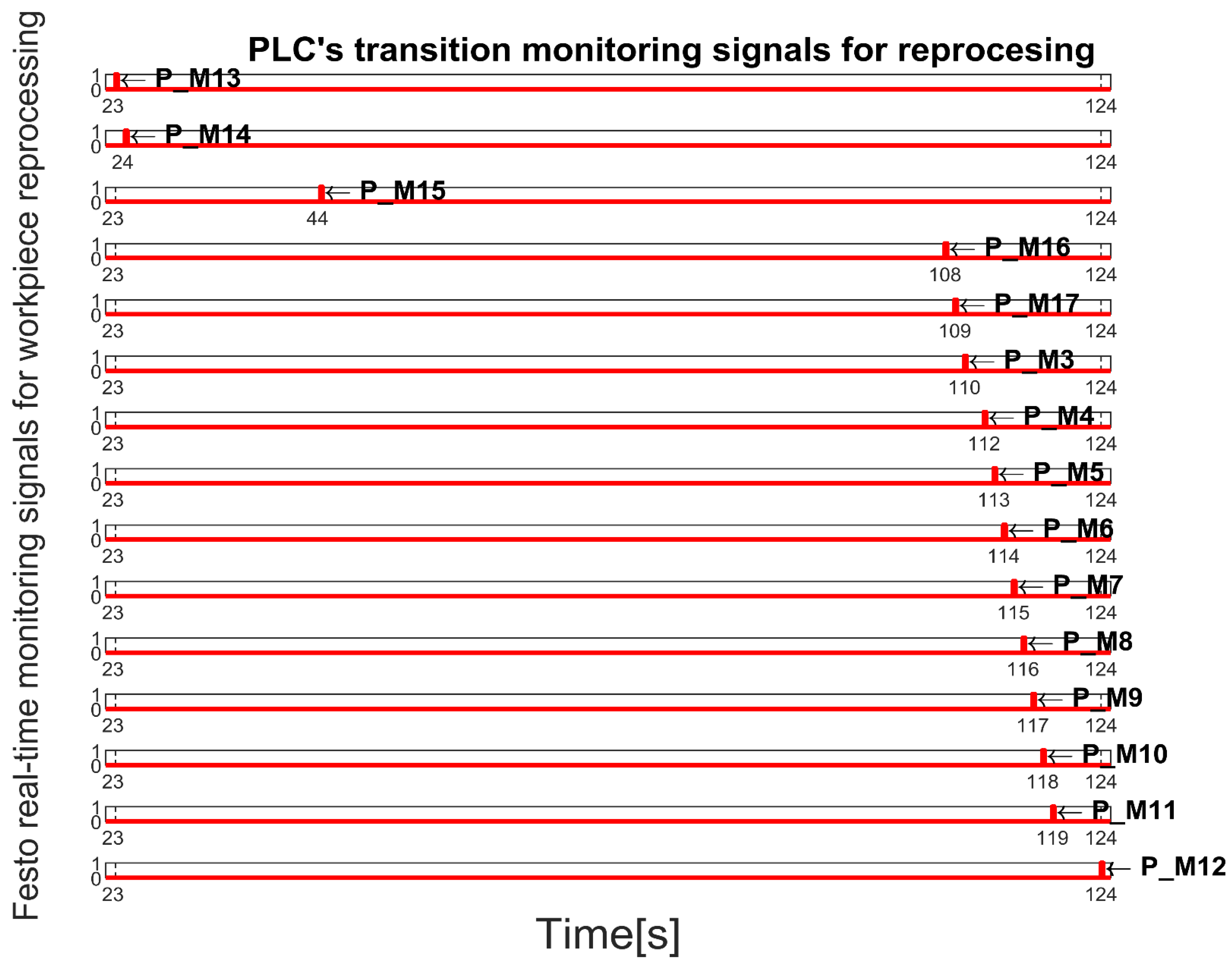
Figure 16.
Monitoring signals from master PLC for WP’s scrapping.
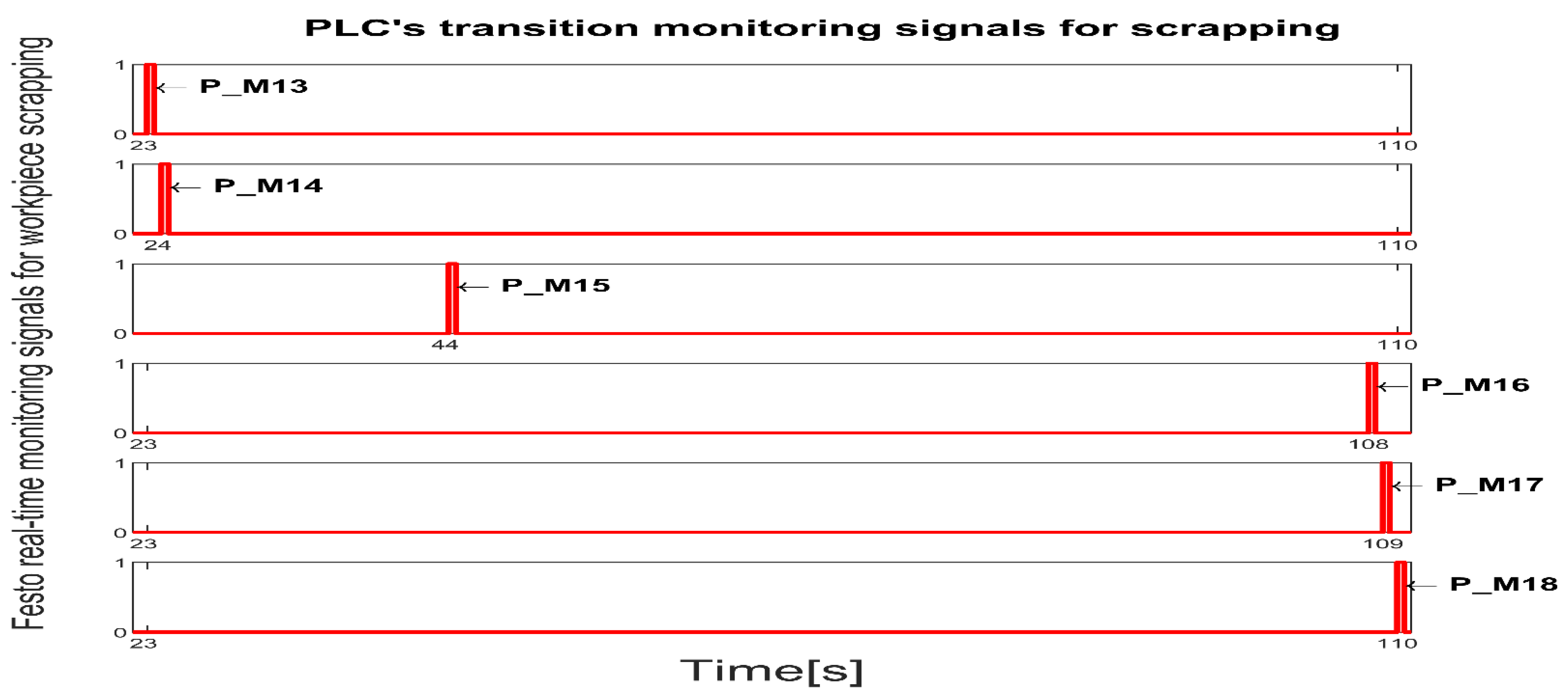
Figure 17.
MCPRS control loops, A) PeopleBot WMR control loop, B): Cyton RM control loop, C) MVSS control loop.
Figure 17.
MCPRS control loops, A) PeopleBot WMR control loop, B): Cyton RM control loop, C) MVSS control loop.
Disclaimer/Publisher’s Note: The statements, opinions and data contained in all publications are solely those of the individual author(s) and contributor(s) and not of MDPI and/or the editor(s). MDPI and/or the editor(s) disclaim responsibility for any injury to people or property resulting from any ideas, methods, instructions or products referred to in the content. |
© 2024 by the authors. Licensee MDPI, Basel, Switzerland. This article is an open access article distributed under the terms and conditions of the Creative Commons Attribution (CC BY) license (http://creativecommons.org/licenses/by/4.0/).
Copyright: This open access article is published under a Creative Commons CC BY 4.0 license, which permit the free download, distribution, and reuse, provided that the author and preprint are cited in any reuse.


