Preprint
Article

This version is not peer-reviewed.

Problems in Modeling Three-Phase Three-Wire Circuits in the Case of Non-Sinusoidal Periodic Waveforms and Unbalanced Load

Submitted:

05 February 2025

Posted:

06 February 2025

You are already at the latest version

Abstract

Asymmetry in the supply voltage in three-phase circuits disrupts the flow of currents. This worsens the efficiency of the distribution system and increases the problems in determining the mathematical model of the energy system. Among many power theories, the most accurate is the Currents' Physical Components (CPC) power theory, which tries to justify the physical essence of each component. Such knowledge can be used to improve efficiency and reduce transmission losses in the power system. The article discusses the method of mathematical decomposition of current components in the case of a three-wire line connecting an asymmetric power source with of linear time-invariant (LTI) loads. Special cases where irregularities appear in the results of calculations according to the CPC theory has been discussed. The method is illustrated with a numerical examples.

Keywords: 
;  ;  

1. Introduction

Contemporary problems in the energy sector mainly focus on improving the efficiency of energy systems and improving energy quality [1,2,3,4]. These activities in the area of power engineering include, among others, monitoring the flow of current and actions to reduce transmission losses [5,6,7]. In this respect, developing methods for describing the mathematical model of the power system and how to determine the values of individual elements is crucial. Knowing the mathematical model of this system will make it possible to select the topology and parameters of the compensators [9,10,11,12,13,14,15,16].
In measurement practice, we most often only have data in the form of measured electrical quantities on the line connecting the load with the power source. This article focuses on the three-wire connection (Figure 1).
Let a linear time-invariant (LTI) load is supplied by a three-wire line with non-sinusoidal and asymmetrical voltage. The assumption of the LTI load is crucial here, because in the case of a receiver generating harmonics [17,18,19,20,21,22,23,24,25,26], identifying all the parameters of the nonlinear load requires a more complicated measurement procedure [27,28,29,30].
There are several power theories that allow the description of an electric circuit in terms of energy. The most important are two theories: the first is the IEEE Standard 1459 [31,32], which is treated as a standard for measurements in electric circuits, and the second is the CPC theory [33,34,35,36,37,38,39,40,41,42,43], which precisely recognizes the individual current components and allows for determining the parameters of compensators.
There is a great conflict in the scientific community between several factions recognizing particular theories. When looking objectively at known power theories, it is necessary to emphasize the advantages of each.
The IEEE Standard 1459, due to its simplicity and simplification, is a good and sufficient way to describe the energy in an electric circuit for billing purposes. Due to the way in which components dependent on physical phenomena are determined, CPC theory is an excellent tool for compensation purposes, design purposes, detailed mathematical analyses and considerations on improving the efficiency of a power system.
The remarks on the CPC theory concerning the incorrectness of the considerations may be considered outdated over time, as work on the detailed description is still in progress and the results obtained bring us ever closer to honoring a universal power theory that does not arouse any controversy. Thanks to the way in which analyses are conducted in this theory, individual components of the current are added to the general mathematical description—analogously to puzzles creating a unified graphic image. If at present day the CPC theory has not taken into account some electrical interaction in the circuit, one can be sure that in the future an additional component will appear which will be a new puzzle in the picture of power theory.
This article focuses on the CPC theory. The first part indicates imprecise descriptions of this theory and proposes corrections supported by computational examples. Next, an analysis was performed for an example measurement scenario.

2. Shift of Vectors by 90°

The voltage measurement [44,45,46,47,48,49,50] in a three-wire system is made with respect to an artificial zero (Figure 1). This circuit is designed in such a way that the three-phase voltage vector does not have a zero symmetrical component. This is possible when the three measuring channels of the voltmeters have the same internal impedances ZV. In practice, the ZV value is many times greater than the source and receiver impedances in the tested system, i.e., the ZV value does not affect the obtained measurements. Current is measured non-invasively using current transformers in the circuit powering a three-phase receiver. This means that the internal impedances ZA of current meters are many times smaller than the source and receiver impedances. By measuring the instantaneous values of voltages and currents and using the FFT transform, amplitudes and phase shifts are obtained for each harmonic separately. The condition is that the current and voltage waveforms are periodic. When making measurements in a real measuring system, we only have access to the line connecting the source with the receiver (Figure 1). The source and receiver are unknown. As a result of measuring the instantaneous values of current and voltage and performing the FFT transformation, three-phase vectors are obtained in the form of:
u n = u R , n u S , n u T , n = 2 e U ¯ R , n U ¯ S , n U ¯ T , n e j n ω 1 t = 2 e U ¯ n   e j n ω 1 t ,   u = n u n , i n = i R , n i S , n i T , n = 2 e I ¯ R , n I ¯ S , n I ¯ T , n e j n ω 1 t = 2 e I ¯ n   e j n ω 1 t ,   i = n i n .
When adopting the definitions of these vectors in accordance with the CPC theory, it should be borne in mind that these vectors are shifted by 90° with respect to the elementary theory, because in this case the instantaneous values are based on the cosine function (2) and not the sine function. For example, for voltage it would be:
u = U 0 + 2 n = 1 U ¯ n cos n ω 1 t + arg U ¯ n .
It is known that the Fourier series coefficients an and bn (3) determined in the period T are:
a n = 2 T 0 T f t cos n ω 1 t d t ,   b n = 2 T 0 T f t sin n ω 1 t d t ,
so in CPC theory these coefficients should be swapped:
f t = a 0 2 + n = 1 b n cos n ω 1 t + a n sin n ω 1 t .

3. Pitfalls in Determining the rms value of Voltage

The active component of current was proposed at the beginning of the 20th century by Prof. Fryze [51]. It makes physical sense for single- and three-phase circuits. As is known, the value of this component is related to the value of active power and the rms value of the voltage. For example, for single-phase circuits, the active component of the current is described by the relations:
i a = u G e = P u ,   i a = G e u = G e U 0 + 2 e n = 1 N G e U ¯ n e j n ω 1 t .
It can be seen in (5) that the value of the ia component and the value of the power P depend on the equivalent conductance Ge. Therefore, Ge is a key parameter in determining the active component, and the value of this parameter is determined from the relationship:
G e = P / u 2 .
For single-phase systems, the rms value of the voltage is equal:
u = U 0 2 + n = 1 U ¯ n 2 .
Let us note that the rms value of voltage (7) is influenced by all components of this voltage that create the instantaneous value u(t) (e.g.,: for a three-phase system it is expressed in formula (2)).
Let us assume a situation in which the kth voltage component (where kN) does not cause a change in the value of the power P in the system. In this situation, the value of the equivalent conductance Ge will not be determined correctly.
Example 1. Let us assume a single-phase receiver constructed from a series connection of a resistor R = 1 Ω and a capacitor C, which for a pulsation of ω1 = 1 rad/s has a reactance XC = 1 Ω. This circuit is powered by voltage u = 1 + 2 cos ω 1 t + cos 3 ω 1 t   V .
According to (7) the rms value of the voltage is: u = U 0 2 + U 1 2 + U 3 2 = 3   V . Active power is the power lost in the resistance R, where for the nth component it is equal: P n = I ¯ n 2 R , while the current is equal I ¯ n = U n R j X C n ω 1 .
The current values are obtained: I ¯ = 0 ;   0.5 + j 0.5 ;   0.9 + j 0.3   A , and powers P = 0 ;   0.5 ;   0.9   W . The total active power is equal P = n P n = 1.4   W , i.e., the equivalent conductance (6) is equal Ge = 0.47 S.
In a series RC connection, the voltage component U0 has no energetic effect and does not affect the value of the current flowing through these elements. The direct current component is equal to I0 = 0 and does not depend on the value of R. The correct rms voltage value must be defined as a parameter that causes some effect in the circuit, so in this example it should be determined from the components U1 and U3.
The correct definition of rms voltage is:
u = n N U n 2 ,
where: N is the set of harmonics for which there is a plexus between the current IN and the voltage UN components, i.e., in this example N = {1, 3}.
The voltage value determined from (8) is equal u = 2   V , this means that the equivalent conductance (6) is equal Ge = 0.7 S. By determining the rms value of the active current component according to (5) and using (7), we obtain i a = 1.4 / 3 = 0.81   A , and after using (8), the value of this current is i a = 1.4 / 2 = 0.99   A .
A similar problem can be seen in three-phase circuits. In three-phase circuits, the definition of the rms value of the three-phase voltage is equal:
u = u R 2 + u S 2 + u T 2 .
The rms values of the L-phase voltages, where L = {R,S,T} are also determined from (8). If there are components of the voltage vector that do not participate in the current flow, the equivalent conductance Ge and the active component of the three-phase current i a will be determined incorrectly.

4. Notes on the Three-Phase Current Components in Time-Domain

In three-phase systems, when there is no symmetry in the power source, symmetrical voltage components with: positive Up, negative Un and zero Uz sequences are used to build mathematical relationships [52,53,54,55]. They are determined from (11), i.e., using three-phase symmetrical unit vectors of the: positive 1p, negative 1n and zero 1z sequences, defined as:
1 p = 1 α 2 α ,   1 n = 1 α α 2 ,   1 z = 1 1 1 .
where: α is the rotation operator which is equal α = e j 120 o = e j 2 π 3 .
U ¯ z U ¯ p U ¯ n = 1 3 1 1 1 1 α α 2 1 α 2 α U ¯ R U ¯ S U ¯ T .
From this point on, mathematical operations are performed individually on the crms values Up, Un, Uz as for a symmetric source. The transformation (11) is performed for each harmonic separately.

4.1. Definition of Instantaneous Values of Three-Phase Symmetrical Voltage for Multiple Harmonics

In three-phase unbalanced periodic and non-sinusoidal voltage waveforms for the nth harmonic, there is no symmetrical voltage component of zero sequence, then the following is true:
U ¯ R , n + U ¯ S , n + U ¯ T , n = 0 ,
In the case of symmetry, for each nth harmonic, the phase shift is equal α or α2. This can be written as an equation:
u L = 2 n = 1 U ¯ L , n cos n ω 1 t + s L + ϕ n = 2 n = 1 U ¯ L , n cos n ω 1 t + arg U ¯ L , n , u L = 2 n = 1 e U ¯ L , n e j n ω 1 t ,
where: L – phase symbol, L = {R,S,T},
sL – phase shift equal to s L = 0 , 2 π 3 , 2 π 3 , meaning: s R = 0 , s S = arg α 2 , s T = arg α ,
ϕn – phase shift between current and voltage for the nth harmonic.
In (13) it can be seen that the argument of the complex number UL,n contains: the rotation vector α, the phase shift angle ϕn and the nth harmonic order:
arg U ¯ L , n = n s L + ϕ n .
Example 2. For the instantaneous voltage value in R phase equal u R = 2 e 230 e j ω 1 t + 20 e j 5 ω 1 t + 2 + 5 e j 7 ω 1 t   V can be written in the time domain: u R = 2 230 cos ω 1 t + 20 cos 5 ω 1 t + 2 + 5 cos 7 ω 1 t   V . According to (13) in the case of symmetry, the voltages in the remaining phases are equal:
u S = 2 230 cos ω 1 t 2 π 3 + 20 cos 5 ω 1 t 2 π 3 + 2 + 5 cos 7 ω 1 t 2 π 3   V , u T = 2 230 cos ω 1 t + 2 π 3 + 20 cos 5 ω 1 t + 2 π 3 + 2 + 5 cos 7 ω 1 t + 2 π 3   V
The graphical waveforms of these voltages are presented in Figure 2.
In (13), the separation of the nth harmonic order and phase shifts: sL, ϕn simplifies the mathematical analysis of three-phase waveforms.

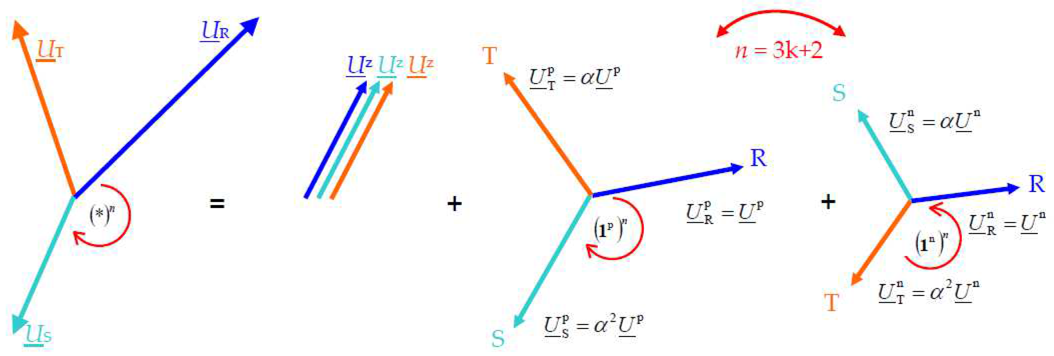
4.2. Using of Symmetrical Components in the Case of Many Harmonics

In the case of sinusoidal waveforms, the three-phase asymetrical source is replaced by the sum of three symmetrical sources, which from (11) for phase R as the reference phase, create the equation:
U ¯ = U ¯ z + U ¯ p + U ¯ n = 1 z U ¯ z + 1 p U ¯ p + 1 n U ¯ n .
where: U ¯ = U ¯ R U ¯ S U ¯ T T .
Similarly to (15), in articles [50] for non-sinusoidal periodic waveforms for the nth harmonic the following relation is used:
U ¯ n = U ¯ n z + U ¯ n p + U ¯ n n = 1 z U ¯ n z + 1 p U ¯ n p + 1 n U ¯ n n .
So far, in the case of periodic non-sinusoidal waveforms, the values of symmetrical components have been determined in the same way as for sinusoidal circuits – i.e., using the transformation (11). For waveforms consisting of many harmonics, the formula (14) is valid. It follows that the turnover factor α is multiplied n times. Therefore, equation (11) for the nth harmonic should look like this:
U ¯ n z U ¯ n p U ¯ n n = 1 3 1 1 1 1 α n α 2 n 1 α 2 n α n U ¯ R , n U ¯ S , n U ¯ T , n ,
while the inverse transformation is described by the relationship:
U ¯ R , n U ¯ S , n U ¯ T , n = 1 1 1 1 α 2 n α n 1 α n α 2 n U ¯ n z U ¯ n p U ¯ n n .
The new vectors 1 n p , 1 n n , arise after raising vectors (10) to the nth power:
1 n p = df 1 p n = 1 α 2 n α n ,   1 n n = df 1 n n = 1 α n α 2 n .
The coefficients (19) was called multiplied three-phase unit vectors.
Example 3. In the three-wire line from Figure 1, where the relationship U ¯ R , n + U ¯ S , n + U ¯ T , n = 0 is valid, the following voltage values were measured:
u R = 2 300 sin ω 1 t + 30 sin 5 ω 1 t + 3 sin 9 ω 1 t   V , u S = 2 250 sin ω 1 t + s S + 25 sin 5 ω 1 t + s S + 2 sin 9 ω 1 t + s S   V , u T = 2 50 31 sin ω 1 t + 128.95 o + 5 31 sin 5 ω 1 t 128.95 o + 5 sin 9 ω 1 t + 180 o   V .
The symmetric components (16) determined from (11), give the solution in the form:
U ¯ n z = 1 3 U ¯ R , n + U ¯ S , n + U ¯ T , n , U ¯ n p = 1 3 U ¯ R , n + α U ¯ S , n + α 2 U ¯ T , n , U ¯ n n = 1 3 U ¯ R , n + α 2 U ¯ S , n + α U ¯ T , n .
After substituting the numerical data, we get:
U ¯ 1 p U ¯ 5 p U ¯ 9 p = 275 + j 25 3 3 5 2 + j 5 3 6 3 2 + j 7 3 6 ,   U ¯ 1 n U ¯ 5 n U ¯ 9 n = 25 j 25 3 3 55 2 j 5 3 6 3 2 j 7 3 6 ,   U ¯ 1 z U ¯ 5 z U ¯ 9 z = 0 0 0 .
The same components determined from (18), give the solution:
U ¯ n z = 1 3 U ¯ R , n + U ¯ S , n + U ¯ T , n , U ¯ n p = 1 3 U ¯ R , n + α n U ¯ S , n + α 2 n U ¯ T , n , U ¯ n n = 1 3 U ¯ R , n + α 2 n U ¯ S , n + α n U ¯ T , n ,
which in this example gives the values:
U ¯ 1 p U ¯ 5 p U ¯ 9 p = 275 + j 25 3 3 55 2 j 5 3 6 0 ,   U ¯ 1 n U ¯ 5 n U ¯ 9 n = 25 j 25 3 3 5 2 + j 5 3 6 0 ,   U ¯ 1 z U ¯ 5 z U ¯ 9 z = 0 0 0 .
Comparing solutions (22) and (24) it should be noted that differences appear when n > 1. In practice, when n = 3k + 2 (where k is a natural number k ∈ {N+}) the positive U ¯ n p and negative U ¯ n n symmetric components are swapped (Figure 3).
The appearance of non-zero U ¯ 9 p and U ¯ 9 n components in equation (22) also indicates an incorrect transformation. When equation U ¯ R , n + U ¯ S , n + U ¯ T , n = 0 is satisfied, the appearance of zero-order harmonics (for n = 3k) is unnatural. In functions (20), in real systems, the amplitude of the 9th harmonic cannot be different from zero. This translates into zero values of a symmetrical component of the zero sequence U ¯ n z for any nth harmonic.

5. Revised CPC Theory Definitions

The introduction of a correction to the decomposition into symmetrical components for periodic non-sinusoidal waveforms results in a different mathematical notation for electrical quantities for three-phase systems.
The vector of the supply voltage u as referenced to an artificial zero of the circuit (Figure 4) can be decomposed into symmetrical components of the positive and the negative sequence:
u = n u n = 2 e n = 1 1 p U ¯ n p + 1 n U ¯ n n e j n ω 1 t = u p + u n .
The symbols U ¯ n p and U ¯ n n in (25) denote the crms values of the symmetrical components of the nth order supply voltage harmonic with positive and negative sequence, respectively. They are equal
U ¯ n p U ¯ n n = 1 3 1 α n α 2 n 1 α 2 n α n U ¯ R , n U ¯ S , n U ¯ T , n .
The three-phase rms value of the supply voltage, equal to the root of the sum of the squares of the effective values of the line voltages, is:
u = L = R , S , T u L 2 ,   where   u L = n = 1 U ¯ L , n 2 .
The load in Figure 5 is equivalent with respect to active power P to a balanced resistive load of conductance Gb:
G b = P u 2 .
The current flowing through such an equivalent load is called the active current and is equal:
i a = i Ra i Sa i Ta = G b u = 2 e n = 1 G b 1 p U ¯ n p U ¯ n p + 1 n U ¯ n n U ¯ n n e j n ω 1 t ,   i a = G b u .
As a result of calculating equation (29), we obtain the same form as in the previous articles that did not take into account the multiplied vector in (26), because the Up and Un components are swapped—which does not affect the result in the case of their sum. However, to improve readability, the elementary division between these components should be maintained.
The load for each harmonic has active and reactive powers. For the nth order harmonic, they are equal:
P n = e U ¯ n T I ¯ n * = e U ¯ R , n I ¯ R , n * + U ¯ S , n I ¯ S , n * + U ¯ T , n I ¯ T , n * ,   Q n = m U ¯ n T I ¯ n * .
When for the nth order harmonic the load is unbalanced, it is useful to define the balanced admittance Yb. This admittance is already symmetrical and depends on the voltage un, the active powers Pn and reactive powers Qn, and is equal:
Y ¯ b , n = G b , n + j B b , n = P n j Q n u n 2 = C ¯ n * L = R , S , T U ¯ L , n 2 .
In definition (31) the symbol “C” was used instead of the symbol “S”. This is an intentional action by authors [50] to avoid confusing the complex power Pn + jQn with the apparent power Sn, which may also contain components other than only active and reactive power. These powers was shown in Figure 6.
The supply current of such an equivalent load consists of the active current (32) and the reactive current (33):
i a , n = G b , n u n = 2 e G b , n 1 p U ¯ n p + 1 n U ¯ n n e j n ω 1 t ,
i r , n = 2 e j B b , n 1 p U ¯ n p + 1 n U ¯ n n e j n ω 1 t .
The ir current component appears in the load current, because of the phase shift of the load current harmonics relative to the supply voltage harmonics. It can be considered as a reactive current component on the load, whose value is:
i r = n i r , n = 2 e n = 1 j B b , n 1 p U ¯ n p + 1 n U ¯ n n e j n ω 1 t .
Yb,n is the admittance of the equivalent balanced load for the nth order harmonic. In practice, the load may be unbalanced, so the nth order harmonic of the load current in may contain the unbalanced current component:
i u , n = i n i b , n = i n i a , n + i r , n = 2 e I ¯ n Y ¯ b , n 1 p U ¯ n p + 1 n U ¯ n n e j n ω 1 t ,   i u = n = 1 i u , n .
In the case of the (32) component, the relation holds:
n = 1 i a , n i a = G b n = 1 u n .
The inequality (36) occurs when the conductance Gb,n for harmonic frequencies are different from the conductance Gb of the equivalent balanced load. The difference between these components is:
n = 1 i a , n i a = 2 e G b , n G b 1 p U ¯ n p + 1 n U ¯ n n e j n ω 1 t = i s .
The current is is called a scattered current component because conductances at harmonic frequencies Gb,n are usually scattered around the balanced conductance Gb and the current is is the effect of this scattering.
The current of the load was presented as the sum of the specific components:
i = i a + i s + i r + i u .
Because of association of this load currents components with physical phenomena in the load, these currents are referred to as the Currents’ Physical Components (CPC). This does not mean that these currents exist physically, as they are mathematical entities, not physical ones.
Each of these currents is associated with a different physical phenomenon in the load. The active current ia is related to the phenomenon of supplying active power P to the load. The scattered current is is related to the phenomenon of changing the equivalent conductance Gb,n with the harmonic order n. The reactive current ir is related to the phenomenon of phase shift of the current relative to the supply voltage for the nth harmonic. The unbalanced current iu is related to the load imbalance for the nth harmonic.
The correction introduced to the definitions presented so far in this article does not change the rms values of these components. Only the equations defined in the time domain change.
The situation becomes more complicated when the unbalanced current component is decomposed and the values of the compensator parameters are determined. In the article [36] the unbalanced current component was decomposed into two elements:
i u = i u p + i u n .
The rms values of both components depend on the division into positive and negative sequence compenents. When equation (16) is taken into account, these components can be represented in the form:
i u p = 2 e n = 1 Y ¯ d , n U ¯ n p + Y ¯ u , n n U ¯ n n 1 p e j n ω 1 t ,
i u n = 2 e n = 1 Y ¯ d , n U ¯ n n + Y ¯ u , n p U ¯ n p 1 n e j n ω 1 t ,
where, according to [36] the voltage asymmetry dependent admittance:
Y ¯ d , n = Y ¯ e , n Y ¯ b , n ,
the equivalent admittance:
Y ¯ e , n = Y ¯ ST , n + Y ¯ TR , n + Y ¯ RS , n ,
and the unbalanced admittances is:
Y ¯ u , n p = Y ¯ ST , n + α Y ¯ TR , n + α 2 Y ¯ RS , n , Y ¯ u , n n = Y ¯ ST , n + α 2 Y ¯ TR , n + α Y ¯ RS , n .
The admittances (42), (43), (44), (31) depend on the admittance values of the three-phase load, while the rotation vector α acts in the same direction of rotation—regardless of the harmonic order.
As a result of changing the values of the symmetrical voltage components U ¯ n p and U ¯ n n , which should be determined from (26), the values of the current unbalanced components (40) and (41) will change. A different way of defining these variables causes the instantaneous and rms values of both components to change, and the formulas determining the reactive compensator parameters must be re-developed.

6. Conclusions

The computational problems revealed in this article are important when performing mathematical analyses in electrical systems powered by sources with periodic non-sinusoidal waveforms.
  • The 90° shift of vectors discussed in point 2 is important in the case of time-domain notation and comparing calculation results with oscilloscope measurements. To deal with this problem, one can use the relationship (4), or each of the determined numerical values in the time domain can be shifted by a constant angle of -90°.
  • The problem shown in point 3 concerns a special case when harmonics appear that do not participate in the transmission of the energy. An example is a situation when the load has a series capacitance, which, as is known, does not carry a DC component. In such a situation, it remains to use formula (8) only for those harmonics that are related to energetic interactions.
  • The method of notation of three-phase waveforms, discussed in point 4, revealed the need to change the definition of symmetrical components (17) when the instantaneous values are described by periodic non-sinusoidal functions. Determining the symmetric components using multiplied three-phase unit vectors (19) improves the mathematical notation. This observation revealed the need to improve the development of algorithms determining the unbalanced components and parameters of reactive compensators. These issues should be considered in further research.

Symbols

1 three phase symmetrical unit vector
a, b Fourier series coefficients
α rotation vector
Bb balanced susceptance, S
C capacitance, F
e electromotive force, emf, V
φ phase shift
Gb balanced resistive load of conductance, S
Ge equivalent conductance, S
i vector of instantaneous currents in a three-phase system, A
I vector of complex currents in a three-phase system, A
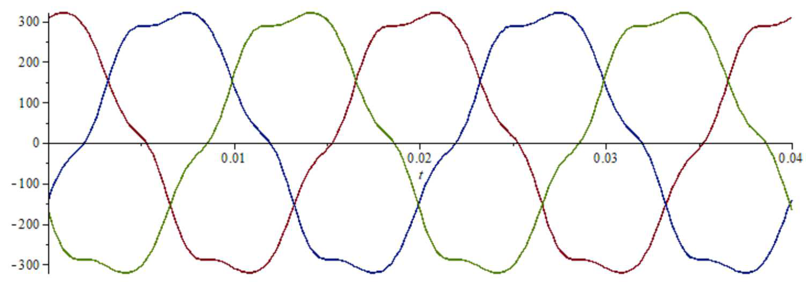
iR, iS, iT instantaneous values of line currents, A
ia active component of the current—three-phase vector, A
ir reactive component of the current—three-phase vector, A
is scattered component of the current—three-phase vector, A
iu unbalanced component of the current—three-phase vector, A
N set of harmonics
P active power, W
Q reactive power, var
R resistance, Ω
sL phase shift
t time, s
T the repetition period of the instantaneous value, rad/s
u vector of instantaneous voltages in a three-phase system, V
U vector of complex voltages in a three-phase system, V
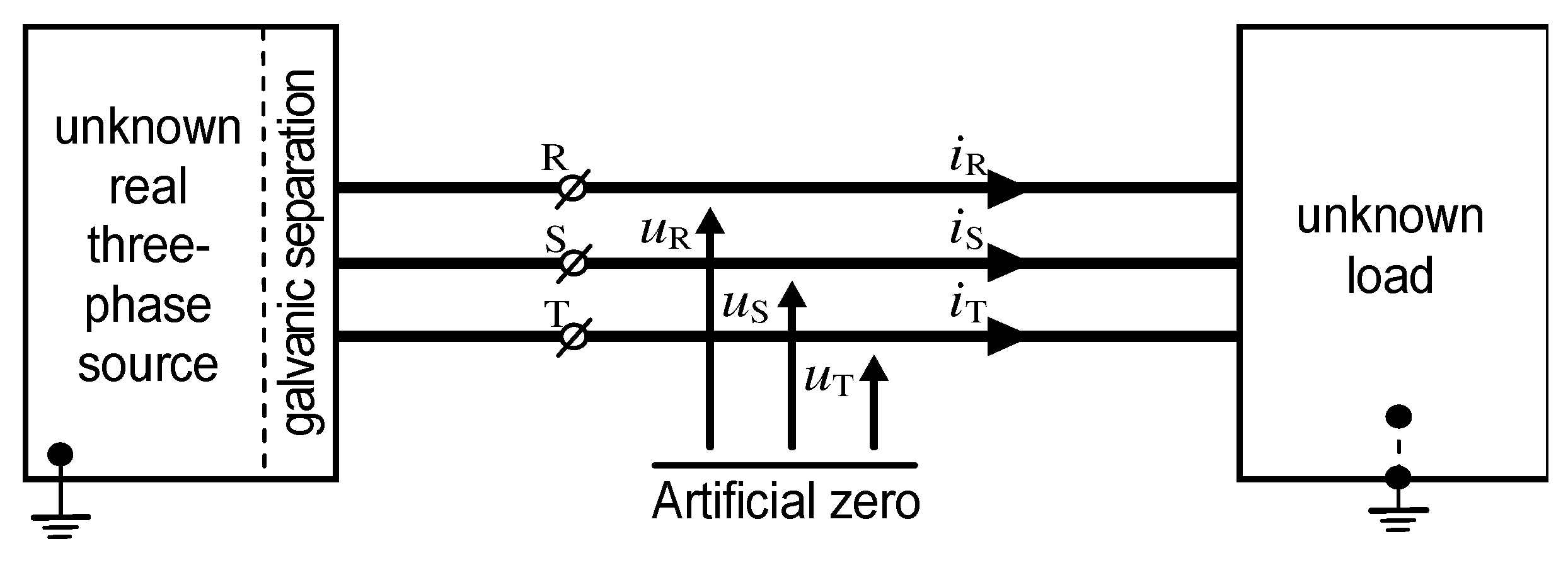
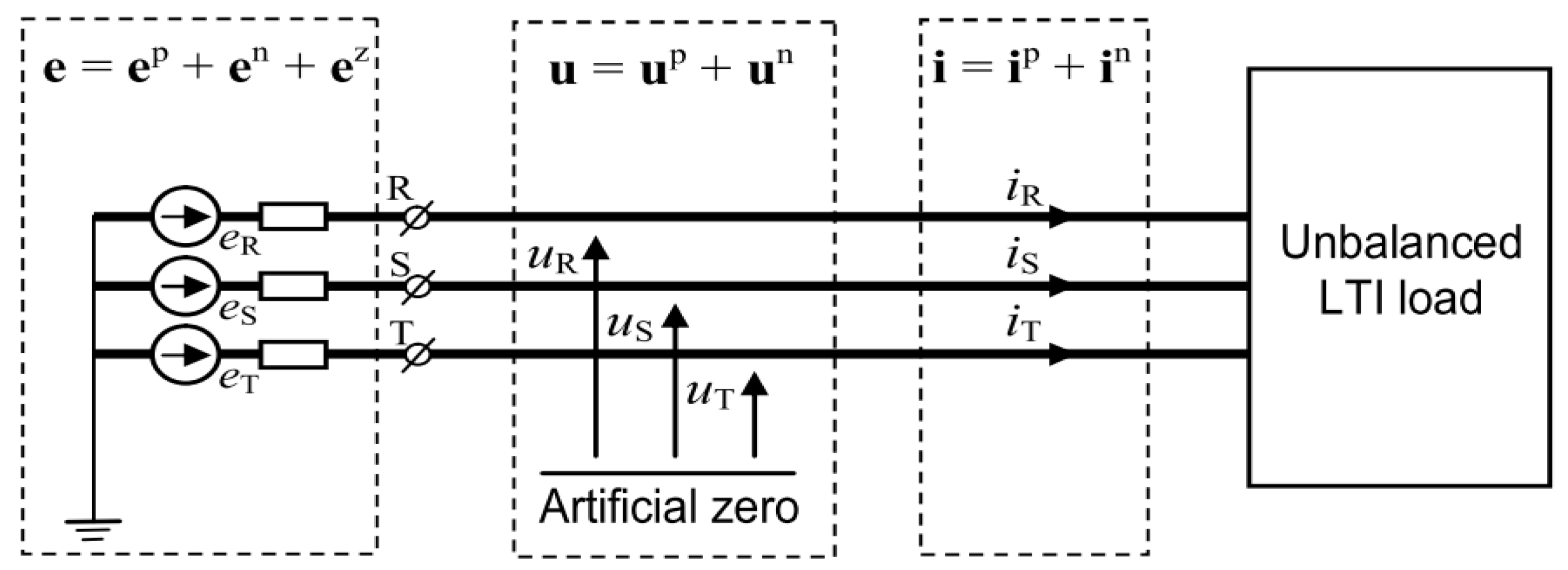
uR, uS, uT instantaneous voltage values relative to the virtual star point, V
ω1 basic pulsation, rad/s
X reactance, Ω
Yb balanced admittance, S
Yd voltage asymmetry dependent admittance, S
Ye equivalent admittance, S
Yu unbalanced admittance, S

Subscripts, Superscripts

R,S,T,N phase and neutral wires
n harmonic number
L phase number, L = {R,S,T}
p, n, z positive, negative, zero sequence

Acronyms

CPC Currents’ Physical Components
crms complex root mean square

Author Contributions

Conceptualization, K.Z.; methodology, K.Z.; validation, S.D; formal analysis, K.Z.; investigation, K.Z.; resources, K.Z. and S.D.; data curation, K.Z.; writing—original draft preparation, K.Z.; writing—review and editing, K.Z.; visualization, K.Z.; supervision, K.Z.; project administration, K.Z. All authors have read and agreed to the published version of the manuscript.

Funding

This research received no external funding.

Institutional Review Board Statement

Not applicable.

Informed Consent Statement

Not applicable.

Data Availability Statement

Data is contained within the article.

Conflicts of Interest

The authors declare no conflict of interest.

References

  1. Zajkowski, K. Reactive power compensation in a three-phase power supply system in an electric vehicle charging station. Journal of Mechanical and Energy Engineering 2018, 2, 75–84. [Google Scholar] [CrossRef]
  2. Gubarevych O, et al. Research and assessment of the reliability of railway transport systems with induction motors. Energies 2023, 16, 6888. [Google Scholar] [CrossRef]
  3. Duer S, et al. Examination of multivalent diagnoses developed by a diagnostic program with an artificial neural network for devices in the electric hybrid power supply system House on Water. Energies 2021, 14, 2153. [Google Scholar] [CrossRef]
  4. Rosinski A, et al. Safety Analysis for the Operation Process of Electronic Systems Used Within the Mobile Critical Infrastructure in the Case of Strong Electromagnetic Pulse Impact. Theory and Applications of Dependable Computer Systems. DepCoS-RELCOMEX 2020. Advances in Intelligent Systems and Computing, vol 1173. Springer, Cham. [CrossRef]
  5. Zajkowski, K. An innovative hybrid insulation switch to enable/ disable electrical loads without overvoltages. E3S Web of Conf. 2017, 19, 01033. [Google Scholar] [CrossRef]
  6. Suproniuk, M. , Pas J. Analysis of electrical energy consumption in a public utility buildings. Przegląd Elektrotechniczny 2019, 95. [Google Scholar] [CrossRef]
  7. Duer S, Zajkowski K. Taking decisions in the expert intelligent system to support maintenance of a technical object on the basis information from an artificial neural network. Neural Computing and Appl. 2013, 23, 2185–2197. [Google Scholar] [CrossRef]
  8. Duer S, et al. Reliability Testing of Wind Farm Devices Based on the Mean-time Between Failures (MTBF). Energies 2023, 16, 1659. [CrossRef]
  9. Czarnecki LS, Bhattarai PD. A Method of Calculating LC Parameters of Balancing Compensators for AC Arc Furnaces. IEEE Trans. on Power Deliv. 2017, 32, 688–695. [Google Scholar] [CrossRef]
  10. Czarnecki LS, Bhattarai PD. Reactive Compensation of LTI Loads in Three-Wire Systems at Asymmetrical Voltage. Przegląd Elektrotechniczny 2015, 91, 7–11. [Google Scholar] [CrossRef]
  11. Czarnecki, L.S. Reactive and unbalanced currents compensation in three-phase circuits under nonsinusoidal conditions. IEEE Trans 1989, IM-38, 754–459. [Google Scholar] [CrossRef]
  12. Czarnecki, L.S. , Almousa M., Adaptive balancing by reactive compensators of three-phase linear loads supplied by nonsinusoidal voltage from four-wire lines. Am. J. Electr. Power Energy Syst 2021, 10, 32–42. [Google Scholar] [CrossRef]
  13. Ginn, H. Chen G. Switching compensator control strategy based on CPC power theory, International School on Nonsinusoidal Currents and Compensation, Łagów, 2008.
  14. Czarnecki, L.S. , Hsu S.M. Thyristor controlled susceptances for balancing compensators operated under nonsinusoidal conditions. IEE Proc.-Electr. Power Appl 1994, 14. [Google Scholar]
  15. Zajkowski, K. , Rusica I., The method of calculating LC parameters of balancing compensators in a three-phase four-wire circuit for an unbalanced linear receiver. IOP Conf. Series: Materials Science and Engineering 2019, 564, 012134. [Google Scholar] [CrossRef]
  16. Zajkowski, K. Two-stage reactive compensation in a three-phase four-wire systems at nonsinusoidal periodic waveforms. Electric Power Systems Research 2020, 184, 106296. [Google Scholar] [CrossRef]
  17. Marcu, M. Popescu F.G., Niculescu T., Pana L., Handra A.D. Simulation of power active filter using instantaneous reactive power theory, 2014 16th International Conference on Harmonics and Quality of Power (ICHQP), pp. 581-585, Bucharest.
  18. Haugan, T.S. Tedeschi E. Active power filtering under non-ideal voltage conditions using the conservative power theory, IEEE 13th Brazilian Power Electronics Conference and 1st Southern Power Electronics Conference (COBEP/SPEC), Fortaleza, 2015.
  19. Rosa, R.B. , Vahedi H., Godoy R.B., Pinto J.O.P., Al-Haddad K. Conservative Power Theory Used in NPC-Based Shunt Active Power Filter to Eliminate Electric Metro System Harmonics, 2015 IEEE Vehicle Power and Propulsion Conference (VPPC), Montreal, QC, 2015.
  20. Zhu, L. , et al., Research on shunt active power filter based on the improved instantaneous reactive power theory, 2015 Sixth International Conference on Intelligent Control and Information Processing (ICICIP), pp. 459-464, Wuhan.
  21. Abdullah, A. , Biswal G.R., Roy A.K. Modeling and control of hybrid power filter using p-q theory, 2016 IEEE 1st International Conference on Power Electronics, Intelligent Control and Energy Systems (ICPEICES), Delhi.
  22. Busarello, T.D.C. , Pomilio J.A., Simões M.G. Passive Filter Aided by Shunt Compensators Based on the Conservative Power Theory. IEEE Transactions on Industry Applications 2016, 52, 3340–3347. [Google Scholar] [CrossRef]
  23. Hanzelka, Z. , Mondzik A. Different LC power filter topologies—effectiveness of reducing voltage distortion. Renewable Energy and Power Quality Journal 2016, 14. [Google Scholar]
  24. Lada, M.Y. , Mohamad S.S., Gani J.A.M., Nawawi M.R.M., Kim G.C. Reduction of harmonic using single phase shunt active power filter based on instantaneous power theory for cascaded multilevel inverter, 2016 IEEE International Conference on Power and Energy (PECon), Melaka.
  25. Mboving CSA., Hanzelka Z. Hybrid Power Active Filter - Effectiveness of Passive Filter on the Reduction of Voltage and Current Distortion. Electric Power Quality and Supply Reliability 2016.
  26. Tobola, A. Mikołajuk K. Multiobjective Optimization Approach to the Active Power Filter Control, Proc.of 17th International Conference Computational Problems Of Electrical Engineering (CPEE), 2016.
  27. Moghaddam, F.K. Farhangi S. Improvement of the stand-alone DFIG performance feeding nonlinear and unbalanced loads using active and reactive power theory, 2015 IEEE Conference on Energy Conversion (CENCON), pp. 128-133, Johor Baru.
  28. Zajkowski K, Rusica I, Palkova Z. The use of CPC theory for energy description of two nonlinear receivers. MATEC Web Conf. 2018, 178, 09008. [Google Scholar] [CrossRef]
  29. Zajkowski, K. , Duer S., Paś J., Pokorádi L. Cooperation of a Non-Linear Receiver with a Three-Phase Power Grid. Energies 2023, 16, 1418. [Google Scholar] [CrossRef]
  30. Zajkowski, K. The method of solutions of equations with coefficients that contain measurement errors, using artificial neural network. Neural Computing and Appl. 2014, 24, 431–439. [Google Scholar] [CrossRef]
  31. IEEE Trial use standard for the measurement of electric power quantities under sinusoidal, nonsinusoidal, balanced and unbalanced conditions. IEEE 1459-2000.
  32. IEEE standard definitions for the measurement of electric power quantities under sinusoidal, nonsinusoidal, balanced and unbalanced conditions. IEEE 1459-2010.
  33. Czarnecki, LS. Orthogonal Decomposition of the Currents in a 3-Phase Nonilnear Asymmetrical Circuit with a Nonsinusoidal Voltage Source. IEEE Trans. on Instr. and Measur. 1988, 37, 30–34. [Google Scholar] [CrossRef]
  34. Czarnecki, LS. Currents’ Physical Components (CPC) concept: a fundamental of Power Theory. Przegląd Elektrotechniczny 2008, 84, 28–37. [Google Scholar] [CrossRef]
  35. Czarnecki LS, Haley PM. Unbalanced Power in Four-Wire Systems and Its Reactive Compensation. IEEE Trans. on Power Deliv 2015, 30. [CrossRef]
  36. Czarnecki LS, Bhattarai PD. CPC−Βased Reactive Compensation of Linear Loads Supplied with Asymmetrical Non-sinusoidal Voltage. Annals University of Craiova 2019, 42, 1–9. [Google Scholar]
  37. Currents’ Physical Components (CPC) in systems with semi-periodic voltages and currents, International School on Nonsinusoidal Currents and Compensation (ISNCC)<italic>, </italic> Łagów.
  38. Czarnecki, L.S. Almousa M., Conversion of fixed-parameters compensator in four-wire system with nonsinusoidal voltage into adaptive compensator. Przegląd Elektrotechniczny 2021, 97. [Google Scholar]
  39. Czarnecki, L.S. , Almousa M. Adaptive Compensation of Reactive, Unbalanced and DC Currents of AC Arc Furnaces. Przegląd Elektrotechniczny 2023, 99. [Google Scholar]
  40. Jeltsema, D. Woude J. Currents’ Physical Components (CPC) in the time-domain: Single-phase systems, European Control Conference (ECC), Strasbourg, 2014.
  41. Martell, F. Izaguirre A., Macías M. CPC power theory for analysis of Arc Furnaces, International School on Nonsinusoidal Currents and Compensation (ISNCC), Łagów, 2015.
  42. Weixing Li, Rahmani B., Liu G. Expansion of Current Physical Components (CPC) to Three-Phase Four-Wire Systems under Non-Ideal Waveforms by the AUPQS. IEEE Conf 2016.
  43. Borges, A.M. , Alves S., Currents’ physical components (CPC): Case studies in single phase systems. IEEE Conf. 2018. [Google Scholar]
  44. Zajkowski K, Rusica I. Comparison of electric powers measured with digital devices relative to powers associated with distinctive physical phenomena. IOP Conf. Series: Materials Science and Engineering 2019, 564, 012133. [Google Scholar] [CrossRef]
  45. Zajkowski, K. Settlement of reactive power compensation in the light of white certificates. E3S Web of Conf. 2017, 19, 01037. [Google Scholar] [CrossRef]
  46. Zajkowski K, Smyczek J. Simulation of overvoltages for switching off lagging load from mains. 2nd International Industrial Simulation Conference 2004, p. 278-281, EUROSIS, 2004.
  47. Duer S, et al. Designing of an effective structure of system for the maintenance of a technical object with the using information from an artificial neural network. Neural Computing and Appl. 2013, 23, 913–925. [Google Scholar] [CrossRef]
  48. Duer S, et al. Analyses of the method development of decisions in an expert system with the use of information from an artificial neural network. MATEC Web Conf. 2018, 178, 07002. [Google Scholar] [CrossRef]
  49. Duer S, et al. Training of an artificial neural network in the diagnostic system of a technical object. Neural Computing and Appl. 2013, 22, 1581–1590. [Google Scholar] [CrossRef]
  50. Bhattarai PD, Czarnecki LS. Currents’ Physical Components (CPC) of the Supply Current of Unbalanced LTI Loads at Asymmetrical and Nonsinusoidal Voltage. Przegląd Elektrotechniczny 2017, 93, 30–35. [Google Scholar] [CrossRef]
  51. Fryze S, Active, reactive and apparent power in circuits with nonsinusoidal voltages and currents. Przegląd Elektrotechniczny 1931, 1932, 7, p. 193–203, 8, p 225.
  52. Zajkowski K, Duer S. Decomposition of the Voltages in a Three-Phase Asymmetrical Circuit with a Non-Sinusoidal Voltage Source. Energies 2023, 16, 7616. [Google Scholar] [CrossRef]
  53. Czarnecki LS, Haley PM. Power Properties of Four-Wire Systems at Nonsinusoidal Supply Voltage. IEEE Trans. on Power Deliv. 2016, 31, 513–521. [Google Scholar] [CrossRef]
  54. Czarnecki, LS. Why the Power Theory has a Limited Contribution to Studies on the Supply and Loading Quality?. 18th Int. Conf. on Harmonics and Quality of Power (ICHQP), 2018. [CrossRef]
  55. Czarnecki, LS. Degradation of the Energy Transfer Effectiveness Described in Terms of Currents’ Physical Components (CPC)-based Power Theory. Int. Symp. on Computer Science and Intelligent Controls (ISCSIC) 2017, 39–48. [Google Scholar] [CrossRef]
  56. Calamero N, et al. Defining the Unique Signatures of Loads Using the Currents’ Physical Components Theory and Z-Transform. IEEE Trans. on Industrial Informatics 2015, 11, 155–165. [Google Scholar] [CrossRef]
  57. Mikulovic J, Sekava T, Skrbio B. Currents’ physical component (CPC) power theory for three-phase four-wire systems. Mediterranean Conference on Power Generation Transmission Distribution and Energy Conversion (MedPower) 2016, 1–7. [CrossRef]
  58. Grasso F, et al. Improvement of Power Flow Analysis based on Currents’ Physical Component (CPC) Theory. IEEE Int. Symp. on Circuits and Systems (ISCAS) 2018. [CrossRef]
  59. Samet H, Ghanbari T, Ghaisari J. Maximum performance of electric arc furnace by optimal setting of the series reactor and transformer taps using a nonlinear model. IEEE Trans. on Power Deliv. 2015, 30, 764–772. [Google Scholar] [CrossRef]
  60. Bielecki S, Skoczkowski T. An enhanced concept of Q-power management. Energy 2018, 162, 335–353. [Google Scholar] [CrossRef]
  61. Czarnecki, L.S. oups T.N., Working and Reflected Active Powers of Three-Phase Loads, 12th International School on Nonsinusoidal Currents and Compensation (ISNCC), Łagów, 2015.
  62. Izaguirre, A.R. Macias M.E., Martell F., Accurate CPC Power Analysis under Extreme EAF’s Distortion Conditions. 12th International School on Nonsinusoidal Currents and Compensation (ISNCC) Łagów, 2015.
  63. Busarello, T.D.C. Péres A., Mortezaei A., Simões M.G., Application of the current decomposition of the Conservative Power Theory in Distributed Energy Resources, 12th IEEE International Conference on Industry Applications (INDUSCON), Curitiba, 2016.
  64. Busarello, T.D.C. , Mortezaei A., Péres A., Simões M.G. Application of the Conservative Power Theory Current Decomposition in a Load Power-Sharing Strategy Among Distributed Energy Resources. IEEE Transactions on Industry Applications 2018, 54. [Google Scholar] [CrossRef]
  65. Siergiejczyk, M. , Pas J., Rosinski A. Modeling of Process of Maintenance of Transport Systems Telematics with Regard to Electromagnetic Interferences. Tools Of Transport Telematics 2015, 531, 99–107. [Google Scholar]
  66. Paś, J. , Rosiński A., Wisnios M., Stawowy M. Assessing the Operation System of Fire Alarm Systems for Detection Line and Circuit Devices with Various Damage Intensities. Energies 2022, 15, 3066. [Google Scholar] [CrossRef]
  67. Popescu, M. Bitoleanu A., Suru V. Currents’ physical components theory implementation in shunt active power filtering for unbalanced loads. International School on Nonsinusoidal Currents and Compensation 2013 (ISNCC), Zielona Góra.
  68. Wisnios, M. , Pas J. The assessment of exploitation process of power for access control system. E3S Web of Conferences 2017, 19, 01034. [Google Scholar] [CrossRef]
  69. Busarello, T.D.C. Simões M.G. Power quality enhancement by means of shunt compensators based on the conservative power theory, Clemson University Power Systems Conference (PSC), Clemson, SC, 2015.
  70. Haugan, T.S. Tedeschi E. Reactive and harmonic compensation using the conservative power theory, Tenth International Conference on Ecological Vehicles and Renewable Energies (EVER), Monte Carlo, 2015.
  71. Janabi, A. Wang B. Hybrid matrix converter based on instantaneous reactive power theory, IECON 2015 - 41st Annual Conference of the IEEE Industrial Electronics Society, Yokohama, 2015.
  72. Javadi, A. Hamadi A., Al-Haddad K. Three-phase power quality device tor weak Systems based on SRF and p-q theory controller, IECON 2015 - 41st Annual Conference of the IEEE Industrial Electronics Society, Yokohama, 2015.
  73. Kong, X. Yuan Y., Huang H., Wang Y. Overview of the instantaneous reactive power theory in three-phase systems, 5th International Conference on Electric Utility Deregulation and Restructuring and Power Technologies (DRPT), pp. 2331-2336, Changsha, 2015.
  74. Abbasi, M. Tousi B. Novel controllers based on instantaneous p-q power theory for transformerless SSSC and STATCOM, 2017 IEEE International Conference on Environment and Electrical Engineering and 2017 IEEE Industrial and Commercial Power Systems Europe (EEEIC / I&CPS Europe), Milan.
  75. Hanzelka, Z. Blueprint for the combinatorial strategy in transactive energy-based control mechanism by using energy flexibility platform and interface, CIRED - Open Access Proceedings Journal, 2017.
  76. Mortezaei, A. Simões M., Savaghebi M., Guerrero J., Durra A.A. Cooperative control of multi-master-slave islanded microgrid with power quality enhancement based on conservative power theory, 2017 IEEE Power & Energy Society General Meeting, Chicago.
  77. Oruganti, V.S.R. V, Bubshait A.S., Dhanikonda V.S.S.S., Simões M.G. Real-time control of hybrid active power filter using conservative power theory in industrial power system. IET Power Electronics 2017, 10, 196–207. [Google Scholar] [CrossRef]
  78. Salim, C. Five-level series active power filter performances based on modified instantaneous reactive power theory for harmonic voltage disturbances compensation, 2017 5th International Conference on Electrical Engineering - Boumerdes (ICEE-B), Boumerdes.
  79. Savant, V. Kadrolkar A., Gupte S. Bidirectional tie-line inverter based on instantaneous reactive power theory for microgrid applications, 2017 Second International Conference on Electrical, Computer and Communication Technologies (ICECCT), Coimbatore.
  80. Taher, S.A. Alaee M.H., Dehghani A.Z., Model predictive control of PV-based shunt active power filter in single phase low voltage grid using conservative power theory, 2017 8th Power Electronics, Drive Systems & Technologies Conference (PEDSTC), Mashhad.
  81. Tobała, A. Mikołajuk K. Reference Signal Detection for Voltage Harmonic Damping in Three-Phase Systems, Proc.of 18th Int.Conf.on Computational Problems Of Electrical Engineering (CPEE), 2017.
  82. Alaee, M.H. Taher S.A., Dehghani A.Z. Improved performance of single-phase shunt active power filter by using conservative power theory and model predictive control, 2018 9th Annual Power Electronics, Drives Systems and Technologies Conference (PEDSTC), Tehran.
  83. Harirchi, F. , Simoes M.G. Enhanced Instantaneous Power Theory Decomposition for Power Quality Smart Converter Applications. IEEE Trans. on Power Electron. 2018. [Google Scholar] [CrossRef]
  84. Kumar, H. Patra J., Yadav A., Pal N., Power quality assessment and improvement of 3-phase 3-wire non-linear system using instantaneous power theory based DSTATCOM, 4th International Conference on Recent Advances in Information Technology (RAIT), Dhanbad, 2018.
  85. Souza, W.A. Liberado E.V., da Silva L.C.P., Paredes H.K.M., Marafão F.P. Load analyser using conservative power theory, International School on Nonsinusoidal Currents and Compensation 2013 (ISNCC), Zielona Góra.
  86. Busarello, T.D.C. Pomilio J.A. Synergistic operation of distributed compensators based on the conservative power theory, IEEE 13th Brazilian Power Electronics Conference and 1st Southern Power Electronics Conference, 2015 (COBEP/SPEC), Fortaleza.
Figure 1. Three-wire connection of the load with the source.
Preprints 148333 g001
Figure 2. Symmetrical non-sinusoidal voltage waveforms from example 2.
Preprints 148333 g002
Figure 3. Graphical interpretation of multiplied three-phase unit vectors, where k is a natural number k ∈ {N}.
Preprints 148333 g003
Figure 4. Decomposition into three-phase symmetrical components.
Preprints 148333 g004
Figure 5. Three-phase load and balanced resistive load equivalent in terms of active power P.
Preprints 148333 g005
Figure 6. Graphical interpretation of the equivalent admittance for the nth order harmonic.
Preprints 148333 g006
Disclaimer/Publisher’s Note: The statements, opinions and data contained in all publications are solely those of the individual author(s) and contributor(s) and not of MDPI and/or the editor(s). MDPI and/or the editor(s) disclaim responsibility for any injury to people or property resulting from any ideas, methods, instructions or products referred to in the content.
Copyright: This open access article is published under a Creative Commons CC BY 4.0 license, which permit the free download, distribution, and reuse, provided that the author and preprint are cited in any reuse.
Prerpints.org logo

Preprints.org is a free preprint server supported by MDPI in Basel, Switzerland.

Subscribe

Disclaimer

Terms of Use

Privacy Policy

Privacy Settings

© 2025 MDPI (Basel, Switzerland) unless otherwise stated