Submitted:
23 January 2025
Posted:
24 January 2025
You are already at the latest version
Abstract
This research investigates how electric vehicle (EV) charging can work together with photovoltaic (PV) power generation through smart charging techniques and a voltage-to-grid (V2G) system. A new model for an electric vehicle charging station (EVCS) was created and evaluated to understand how well it works, how it can be improved, and how efficient it is. By combining the EVCS with the PV system, the goal is to decrease power wastage, boost PV self-usage, and decrease customer costs. The charging station model features a centralized charging station offering both slow and fast battery charging options, along with two levels of charging voltage choices (48V and 60V) within a 2.5kW-capacity PV system. The model simulation runs on Simulink MATLAB software. To control the voltage, current, and state of charge (SoC) of electric vehicle batteries during charging and discharging, a method called constant current-constant voltage (CC-CV) is utilized. This method focuses on maximizing charging power effectively and preventing battery overcharging. To achieve this, fuzzy logic controllers adjust the duty cycle and keep the current and voltage stable. In the V2G system, electric vehicles (EVs) can charge, discharge, and serve as energy storage for the grid. Moreover, smart charging is being implemented to improve coordination among electric vehicles, local electricity production, and other power needs. Through a particular control system, EVs can be charged when there is a surplus of solar power but will refrain from charging during peak energy usage times.
Keywords:
EV
; PV
; V2G
; EVCS
; CC-CV
; SoC
1. Introduction
When photovoltaic (PV) systems are linked to the grid, they function as generation units within the power system. These systems can be incorporated into the power grid either centrally or in a distributed manner. Centralized PV systems resemble traditional utility-scale power plants in their size, location away from end-users, and connection to transmission grids or occasionally medium voltage (MV) distribution grids. On the other hand, decentralized PV systems are typically smaller in scale, widely dispersed, located nearer to consumers, and frequently linked to the distribution network [1]. The integration of PV systems into the power system can lead to several problems, such as overvoltage and component overloading. These can shorten the lifespan of electrical system components and need costly grid upgrades [2]. One of the main difficulties associated with PV systems is their unpredictable generation patterns. Unlike conventional power plants that can be adjusted to meet specific demands, PV systems without battery storage cannot be controlled and are considered non-dispatchable sources of power. This limitation poses a significant challenge as power plants are typically designed to cater to the fluctuating power needs of consumers. PV power production fluctuates throughout the year and the day, influenced by the sun's movement across the sky. The highest levels of PV power are typically generated around midday during sunny summer days, significantly surpassing production levels at other times of the day. Production is completely halted during nighttime hours. In addition to these predictable patterns, power generation can be further affected by intermittent cloud cover, leading to a decrease in energy production [3]. This variable aspect of PV power can lead to several problems, such as voltage and frequency fluctuations. Adding storage components, such as batteries, can overcome the problems.
The power grid has a restricted capacity for accommodating distributed generations (DGs) like PVs and new loads such as electric vehicles (EVs) without expensive upgrades to the utility system. Nevertheless, when PVs and EVs are connected to the grid, there is often a discrepancy between energy demand and power generation. One way to address this issue is by harnessing the synergy between PVs and EVs through coordination, control, and implementing smart charging strategies for EVs [2,4,5]. The inclusion of PVs as DGs and high-consuming loads such as EVs not only interrupted the grid performance but also offered opportunities for grid performance improvement [6,7]. Figure 1 presents the underlying power system theory of PV-EV integration in the power grids.
Figure 1(a) illustrates a PV system and EVs in the distribution grid. Simplified electric circuit representations when being power consumer, power producer, and in a state of power balance are shown in Figure 1 (b)-(d), respectively. In Figure 1 (b)-(d), PDG is the DG power generation (kW), PL is the load (kW), VT is the voltage level at the transformer substation (V), VL is the voltage level at load/customer’s side (V), ITL is the current flowing from transformer to load (A), ILT is the current flowing from load to transformer (A), Ploss is the dissipated power loss (kW), R is the equivalent resistance of the feeder (Ω), X is the equivalent reactance of the feeder (Ω), j is an imaginary unit, cos φ is the power factor, sin φ is the reactive power factor, QL is the reactive power in the customer’s side (kVA). Figure 1(b) shows the phenomenon of voltage drop, assuming a much higher value of R compared to X in typical distribution grids [8]. When a customer is using electricity, the voltage on their side is often lower than the manageable voltage level at the substation. This voltage drop is primarily due to the current flowing through the cables and the resistance they offer, leading to power loss in the form of heat. During times of excessive demand, there is a possibility of undervoltage, where the voltage falls below safe levels, and the components may become overloaded with too much current or heat. This situation poses risks to both the users and the appliances being used [9]. The phenomenon of voltage rise is shown in Figure 1(c)., when the customer is a power producer, the voltage level on the customer’s side is typically higher than the controlled voltage level in the substation. Power losses occur as heat when currents travel from the customer's end to the substation. Excessive generation poses risks like overvoltage, exceeding safe limits, and component overloading due to high current or heat. When a power producer achieves a balance between production and consumption, with zero reactive power, the voltage on the customer's end usually stays within a safe range. Furthermore, there are no power losses, since no current flowing between the substation and the customer, as shown in Figure 1(d).
When an EV is connected to the power grid for charging, it functions as a consumer of electricity within the power system. The current power grid infrastructure was not originally built to accommodate a high volume of EV charging demands, which may present new challenges when a significant number of EVs are added to the power system [10,11]. The challenges include undervoltage problems and component overloading [10]. These issues result in a reduction in the lifespan of power grid equipment like substation transformers. In such instances, there may be a need to invest in upgrading the power grid, which can be quite expensive. Typically, the greater the charging power of an EV charger, the greater its effect on the power system. Using higher power chargers can result in increased load variability as the EV charging load fluctuates more frequently and rapidly [12]. This phenomenon is called a voltage-to-grid (V2G) scheme.
This paper proposes the design of an EV battery charging station within a grid-connected PV system, which is simulated in the Simulink MATLAB platform to synergize PV-EV power generation by applying a smart charging scenario and V2G scheme. The sections of this paper are arranged as follows; Section 1 addresses the need to design and simulate the EV battery charging station within a grid-connected PV system. Section 2 literates the enhancement of PV-EV synergy, or we called it the V2G scheme, through a brief review of EVs’ smart charging scenario, as well as its mathematical models and algorithms. Section 3 describes the simulation process of designing the EV battery station within the PV system. Section 4 discusses the results, and last but not least, Section 5, concludes the works.
2. Methods
2.1. Enhancing PV-EV Synergy (V2G Concept)
Analytical methods and design charts used for the simulation throughout the Simulink Matlab platform. The simulation describes the PV system, the charging station, the smart charging of the EV battery scenario, and the V2G scheme. The V2G concept was in the author’s previous article [13]. The V2G system necessitates broad involvement and a centralized scheduling mechanism for managing the charging and discharging activities of electric vehicles. The advantages and obstacles associated with the V2G concept are explored in detail [14], which also overcomes features such as active power regulation, reactive power support, load balancing, and current harmonic filtering. However, the challenges include reduced battery life, communication overhead between EVs and grids, and changes in distribution network infrastructure are also shown. The integration of EVs into the grid offers solutions for energy storage and system services. Figure 2 illustrates the V2G concept, which describes the mentioned integration.
V2G technology refers to the process of transferring surplus energy from electric vehicles back to the smart grid. V2G, or vehicle-grid integration (VGI), helps in providing additional electricity to the energy grid during periods of high demand. This technology also serves as a supplementary power source when renewable energy sources, which are reliant on weather conditions, are not accessible. An example of this scenario is when a residence relying on solar power is unable to produce electricity during nighttime hours. However, an electric vehicle could serve as an alternative power source in such situations [15].
According to [16], Electric vehicles are used as mobile energy storage units to meet peak load power requirements. This involves various power electronics components such as a motor, powertrain inverters, batteries, converters, and an on-board charger. The integration of V2G technology introduces advanced power electronics systems like smart grids and smart charging stations. Supervising the management of the charging and discharging of electric vehicle batteries should be conducted remotely, taking into consideration factors such as the level of battery discharge, power grid demand, battery and grid technical status, smart or traditional grid type, terms of the agreement between the vehicle owner and utility company, and the planned journey time and distance for the electric vehicle user.
2.2. Smart Charging Scenario
While the technology for exchanging electricity between EVs and homes is established, the process of transferring power from EVs to the smart grid is still in the testing phase. The key factor for V2G implementation is ensuring compatibility between electric vehicles and the smart grid. Standardizing smart grids and charging stations is crucial for the advancement of V2G technology, and the IEEE is currently working on standardization efforts in this area. To facilitate the integration of V2G technology, EVs and their chargers, referred to as power conversion equipment, are designed to be intelligent and capable of regulating the charging and discharging processes in different grid situations. Testing the performance of these systems necessitates the use of a genuine bi-directional power supply that can both supply and absorb power in various directions, as well as replicate a range of grid conditions. International standards impose strict and complicated test procedures requiring a flexible tool to generate all kinds of grid scenarios. V2Gs are needed to be tested according to various standards such as IEEE 1547 / UL 1741 / UL 458 / IEC 61000-3-15 / IEC 62116 [17], etc.
2.3. V2G Algorithm
Batteries are widely recognized as efficient and environmentally friendly energy storage systems. Despite their benefits, batteries are prone to damage during use, making it difficult to assess their condition. Battery degradation is influenced by various factors including charging and discharging rates, depth of discharge (DoD), temperature, voltage, cycle number, and storage state of charge (SoC). Quantifying these factors can be complex [18,19,20]. Battery degradation can be categorized into two main types: calendar aging and cycle aging. Calendar aging occurs when the battery is not in use, while cycle aging occurs during the charging and discharging process. The key factors influencing calendar aging are battery temperature and SoC, whereas cycle aging is influenced by the number of charge-discharge cycles, charging rate, and DoD. As a result, the increased number of charging cycles resulting from the V2G service then expedites the deterioration of the battery.
Aside from issues with battery degradation, the V2G method places importance on optimizing the efficiency of both charging and discharging processes. Loss of power during the charging and discharging of electric vehicle batteries is a common occurrence, largely attributed to power electronics like converters. These power electronics typically operate most efficiently when operating near the upper limit of their power range. Moreover, power electronics demonstrate greater efficiency during the charging process compared to discharging. This is due to the higher voltage present during charging as opposed to discharging at an equivalent power output. The elevated charging voltage results in a decreased charging current, consequently minimizing internal resistance losses.
The proposed V2G algorithm provides the constant current-constant voltage (CC-CV) method using two fuzzy logics to mitigate the EVs' battery's voltage, current, and SoC. As the battery charging and discharging process runs, this method maximizes the charging power in a short period and prevents overcharging the battery. The first and second fuzzy logic controls adjust the duty cycle so that both the current and voltage can be constant.
2.4. Simulation Process
To ensure the validity and accuracy of the simulation, its steps and configuration are shown in Figure 3. The flow chart of the simulation of the charging stations’ models and test conditions is shown in Table 1.
The process of generating power through V2G technology is essential while electric vehicles are in operation. Different types of electric vehicles, including fuel-cell cars, battery-electric cars, and plug-in hybrids, are available in the market. To reduce peak energy consumption, the batteries of electric vehicles can be recharged during times of lower demand. In [18], it states that every EV requires three components: (a) a network connection for power flow, (b) a logical interface for control with the grid operator, and (c) an onboard instrumentation system that monitors the vehicle. Each charging dispatch of the battery comes with advantages and disadvantages. The uncontrolled charging-discharging approach allows EVs to charge or discharge at rated power as soon as it is plugged in until the battery’s storage level equals the maximum state of charge (SoC) or unplugged [19,20].The controlled charging system provides electric vehicle owners with the flexibility to make charging choices independently. However, unregulated charging practices could potentially damage local distribution grids due to issues such as power loss, imbalance in supply and demand, reduced lifespan of transformers, and harmonic distortion [21]. Uni-directional over controlled charging-discharging dispatch allows system operators to authorize over whenever EVs are charged and discharged [19,22,23]. However, EV owners must hand over the control to the system operators or aggregators as soon as the EV is plugged in. A delayed controlled charging strategy provides ancillary services to power grids by using more straightforward price signals to incentivize EV owners. Table 2 summarizes the differences between the three EV charging and discharging dispatches.
The three categories of charging dispatches are known as smart charging scenarios. These scenarios enable electric vehicle (EV) owners to control the charging or discharging of their EVs according to specific time frames and rates in order to meet predetermined objectives, such as reducing charging expenses or maintaining a balance between energy demand and supply. Despite this, many EV owners lack a clear understanding of the financial advantages associated with smart charging. Figure 4 depicts the charging and discharging operations of the three strategies that were previously mentioned.
The electric vehicle charging system is designed to incorporate renewable energy sources, notably solar panels, along with a battery power storage system. There are two models involved in this system - the Battery Model (BAT) and the Inverter Model (INV). Each model serves specific purposes and offers distinct advantages in maintaining the effectiveness and longevity of the electric vehicle charging system.
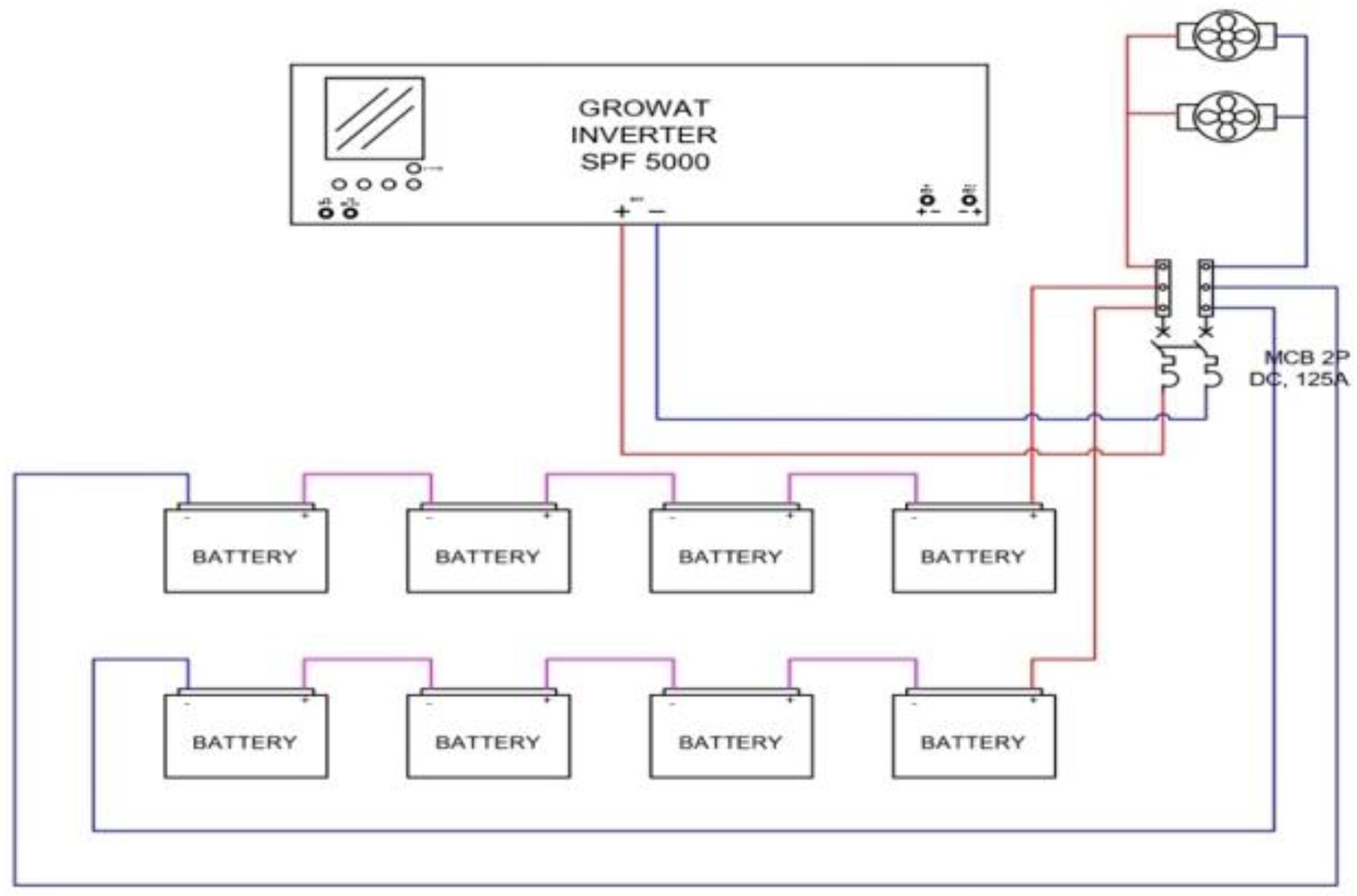
Figure 5.
Model of battery charging station - Battery (BAT).
This particular model prioritizes the utilization of batteries as the primary element for storing power in the electric vehicle charging setup. The energy generated by solar panels, with PV 1 and PV 2 serving as energy inputs, undergoes processing by the Growatt SPF 5000 inverter. This inverter is tasked with transforming the solar panel energy from DC to AC, enabling it to charge the battery effectively. This setup consists of multiple batteries placed in a series, with each battery safeguarded by a 125A 2P DC MCB for overcurrent protection. This configuration enables the stored energy in the batteries to be utilized for charging electric vehicles in the absence of grid power or as a source of backup energy during emergencies.
This model's primary benefit lies in its capability to store surplus energy generated by solar panels in batteries for later use, such as charging electric vehicles or feeding energy back into the grid with a V2G system. Moreover, the battery system offers flexibility in managing energy, enabling the charging station to function uninterrupted even during main network outages. This feature enhances the reliability and efficiency of electric vehicle charging, particularly in regions prone to power interruptions.
The second model emphasizes the control of power transmission from the solar panels to the inverter and then to the AC output for electric vehicle charging. It utilizes the Growatt Inverter SPF 5000 to convert DC power from the solar panels into reliable AC power. An essential component of this model is the inclusion of multiple 2P DC MCBs with a 16A capacity, serving as safeguards against overcurrent. Furthermore, this system is also furnished with a Surge Protection Device (SPD) rated at 150V, serving a crucial function in safeguarding system elements against voltage surges that have the potential to harm the device.
The charging station INV model is designed to efficiently control power distribution from solar panels to the grid or electric vehicles, offering a versatile solution for utilizing renewable energy in vehicle charging. The inverter plays a crucial role in maintaining stable and secure energy flow to the electric vehicle or grid, especially if there is a vehicle-to-grid (V2G) function. Additionally, the surge protection device (SPD) and reliable grounding safeguard the system against voltage spikes, reducing the risk of damage from unforeseen power fluctuations. In general, both models aim to enhance the efficiency and safety of eco-friendly public EV charging stations.
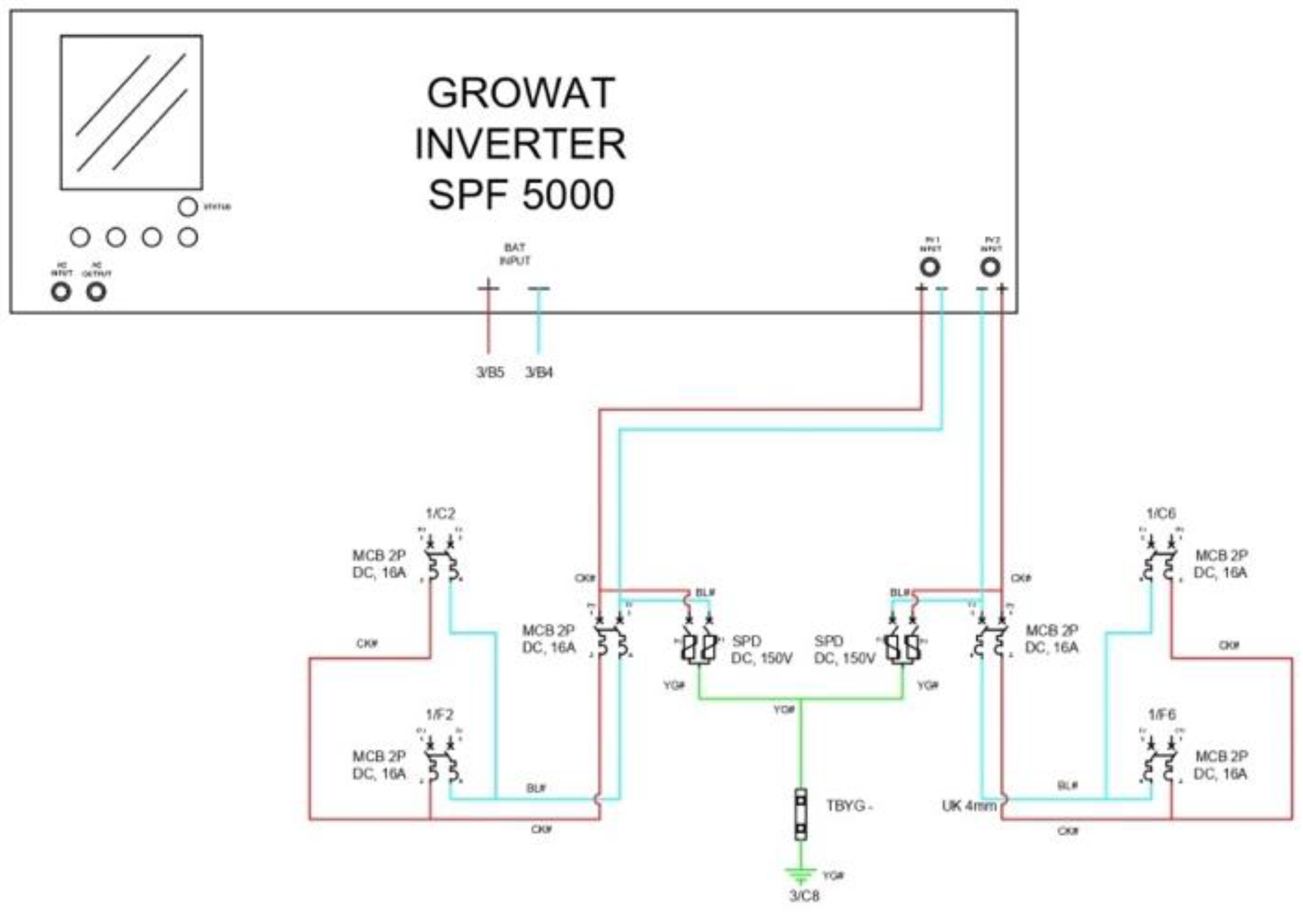
Figure 6.
Model of battery charging station - Inverter (INV).
The BAT model focuses on adaptable and dependable power storage, whereas the inverter-based model prioritizes efficient power distribution and safeguarding from solar panels. By combining these models in the EV charging system, it is possible to lessen reliance on traditional networks, promote the shift towards clean energy, and ensure the sustainability of charging station operations in diverse circumstances. This aligns with worldwide initiatives aiming to encourage the use of electric vehicles as a greener and more energy-efficient option for future transportation needs.
3. Results
3.1. Simulation Result of PV-EV Synergy
First, let us assume the PV is at a certain watt peak value, and a specified array and temperature (oC), whereas it has ten series modules and two parallel strings. The display I-V and P-V characteristics of the PV can be seen in the following Figure 7.
3.2. Simulation Result of the CC-CV Method
Power electronics play an important role as the CC-CV method is implemented as the charging process occurs. A CC-CV algorithm is used to charge and discharge a battery. The Battery CC-CV block is charging and discharging the battery for 10 hours. The initial SoC is 0. When the battery is charging, the current is constant until the battery reaches the maximum voltage and the current decreases to 0. When the battery is discharging, the model uses a constant current.
Figure 8 displays how the battery is charged consistently with both current and voltage under constant charging conditions. The voltage switches from constant current to constant voltage when it reaches its highest state of charge. Two separate control systems are utilized once both criteria are satisfied. When the voltage hits the peak level of the battery, the method of charging shifts from constant current to constant voltage. The transition occurs when the voltage and current are both at one-third of their maximum values. SoC then increases power as the transition progresses in both scenarios. The goal of the CC-CV method is to maximize power and minimize the time it takes to charge the battery.
3.3. Simulation Result of Charging Dispatch Strategy and Power Flow
The microgrid consists of PV generation, a battery, an emergency generator, loads, and a V2G-enabled EV charging station. When the microgrid is connected to the main grid, the battery is used for solar smoothing, peak shaving, and energy arbitrage. The batteries and PV inverters are then used in grid-following mode. When the microgrid is disconnected from the main grid, the battery inverter acts as the primary power source while the PV inverter adjusts its power output accordingly. The emergency generator kicks in only when the battery is depleted and there is not enough solar energy being produced. The electric vehicle batteries can provide backup power for both the microgrid and the main electrical grid.
Figure 9 shows how batteries react during controlled and uncontrolled charging. The results from the controlled charging indicate that three electric vehicles were charged within 55 seconds of the simulation. During the same time frame, only two electric vehicles were being charged. The graph in Figure 10 shows the response to controlled dispatch with a yellow line and uncontrolled dispatch with a blue line. The graph displays: i) the amount of power consumed during both controlled and uncontrolled dispatch; ii) the current flowing through the system; iii) the DC link voltage; iv) the power absorbed from the grid into the vehicle; v) the power consumed by the industrial load; vi) the power flowing through or from the battery.
In V2G operation, electricity moves from the battery to the grid. The charger should be able to handle AC power with a sinusoidal current, just like in G2V mode. The DC-DC converter needs to consistently take power from the battery. Therefore, the battery current rises gradually to make up for the voltage decrease that occurs naturally during the discharge process. In Figure 11 (a), the power grid voltage (vS) and AC output current (iS) over two grid cycles. Figure 11 (b) displays the battery current (iTB) and voltage (vTB) over a two-hour operation period.
The G2V operation mode of the bidirectional charger produced simulation results. In Figure 12 (a), the power grid voltage (vS) and AC input current (iS) are displayed over two grid cycles. The input current is shown to be nearly sinusoidal and synchronized with the power grid voltage, confirming the effectiveness of the hardware topology and control algorithm utilized in the full-bridge AC-DC bidirectional converter. In Figure 12 (b), we can observe the battery charging current (iTB) and voltage (vTB) in the initial two hours of operation. For a more accurate outcome, this simulation employs a battery model that is set up to mirror an actual battery pack. During this period, the battery current remains steady while the battery voltage rises in a nearly straight line. This setup guarantees the proper functioning of the DC-DC reversible converter.
4. Conclusions
A study was conducted on the EV charging station in a grid-connected PV system. The investigation noted that when the voltage reaches its highest state of charge (SoC), it transitions from constant current (CC) to constant voltage (CV). To meet both criteria, two different control systems are utilized. When the battery's voltage nears its maximum level, a CV charging approach is used instead of CC charging. The EV charging station connects to the main grid and consists of PV panels, a battery, an emergency generator, and various loads. The battery serves multiple purposes, such as smoothing out solar power fluctuations, reducing peak energy usage, and optimizing energy trading. The batteries and solar inverters were then utilized in grid-following mode. Once the microgrid is set up, the battery inverter works in grid-forming mode while the PV inverter operates in grid-following mode. The emergency generator is activated only when the battery runs out, and there is not enough PV generation available. The EV batteries can supply energy to both the microgrid and the electric grid.
Acknowledgments
This research was funded by the Ministry of Higher Education of Republic Indonesia for the Electric Battery Consortium 2024.
References
- T. Ackermann, G. Andersson, and L. Söder, “Distributed generation: A definition,” Electr. Power Syst. Res., vol. 57, no. 3, pp. 195–204, 2001. [CrossRef]
- R. Luthander, Self-Consumption of Photovoltaic Electricity in Residential Buildings. 2018.
- . [CrossRef]
- M. H. J. Bollen and S. K. Rönnberg, “Hosting capacity of the power grid for renewable electricity production and new large consumption equipment,” Energies, vol. 10, no. 9, 2017. [CrossRef]
- F. Gonzalez Venegas, M. Petit, and Y. Perez, “Active integration of electric vehicles into distribution grids: Barriers and frameworks for flexibility services,” Renew. Sustain. Energy Rev., vol. 145, no. August 2020, p. 111060, 2021. [CrossRef]
- S. Singh and M. K. Verma, “Sustainable Energy , Grids and Networks Smart charging schedule of plug-in electric vehicles for voltage support : A prosumer-centric approach,” Sustain. Energy, Grids Networks, vol. 33, p. 100972, 2023. [CrossRef]
- P. S. Catal, “Prosumer Flexibility : A Comprehensive State-of-the-Art Review and Scientometric Analysis,” pp. 1–32, 2020.
- “Power-System-Analysis-by-Hadi-Saadat-Electrical-Engineering-libre.pdf.”.
- I. Press et al., POWER SYSTEM PROTECTION.
- P. By and S. By, “Universidad del pais vasco euskal herriko unibertsitatea escuela de ingeniería de bilbao bilboko ingenieritza eskola,” 2016.
- M. Shepero, “Modeling and forecasting the load in the future electricity grid Spatial electric vehicle load modeling and residential load forecasting”.
- U. H. Ramadhani, R. Fachrizal, M. Shepero, J. Munkhammar, and J. Wid, “Probabilistic load flow analysis of electric vehicle smart charging in unbalanced LV distribution systems with residential photovoltaic generation,” vol. 72, no. May, 2021. [CrossRef]
- M. Nasir, N. Safitri, Rachmawati, Yassir, and M. Arhami, “A Concept of V2G Battery Charging Station as the Implementation of IoT and Cyber Physical Network System,” Int. J. Electron. Telecommun., vol. 69, no. 2, pp. 269–273, 2023. [CrossRef]
- M. S. Mastoi et al., “A study of charging-dispatch strategies and vehicle-to-grid technologies for electric vehicles in distribution networks,” Energy Reports, vol. 9, pp. 1777–1806, 2023. [CrossRef]
- M. Sandström, C. Bales, and E. Dotzauer, “Hosting Capacity of the Power Grid for Electric Vehicles - A Case Study on a Swedish Low Voltage Grid,” IOP Conf. Ser. Earth Environ. Sci., vol. 1050, no. 1, 2022. [CrossRef]
- “Battery Charging Control (Fuzzy Logic).pdf.”.
- T. Basso, “IEEE 1547 and 2030 Standards for Distributed Energy Resources Interconnection and Interoperability with the Electricity Grid IEEE 1547 and 2030 Standards for Distributed Energy Resources Interconnection and Interoperability with the Electricity Grid,” Nrel, no. December, p. 22, 2014.
- Z. Wang and S. Wang, “Grid Power Peak Shaving and Valley Filling Using Vehicle-to-Grid Systems,” IEEE Trans. Power Deliv., vol. 28, no. 3, pp. 1822–1829, 2013. [CrossRef]
- B. K. Sovacool and L. Noel, “Science and Engineering A State of the Art Review of Electric Vehicle to Grid ( V2G ) technology A State of the Art Review of Electric Vehicle to Grid ( V2G ) technology,” 2019. [CrossRef]
- A. Barré, B. Deguilhem, S. Grolleau, M. Gérard, F. Suard, and D. Riu, “A review on lithium-ion battery ageing mechanisms and estimations for automotive applications,” J. Power Sources, vol. 241, pp. 680–689, 2013. [CrossRef]
- M. Shahid, S. Zhuang, H. Mudassir, and M. Haris, “Review article A study of charging-dispatch strategies and vehicle-to-grid technologies for electric vehicles in distribution networks,” Energy Reports, vol. 9, pp. 1777–1806, 2023. [CrossRef]
- C. Scott and M. Ahsan, “Machine Learning Based Vehicle to Grid Strategy for Improving the Energy Performance of Public Buildings,” 2021.
- T. Kern, P. Dossow, and S. Von Roon, “Integrating Bidirectionally Chargeable Electric,” 2020.
Figure 1.
(a) DG into grid and its simplified electric circuit representations when being (b) power consumer, (c) power producer, and (d) in power balance.
Figure 1.
(a) DG into grid and its simplified electric circuit representations when being (b) power consumer, (c) power producer, and (d) in power balance.
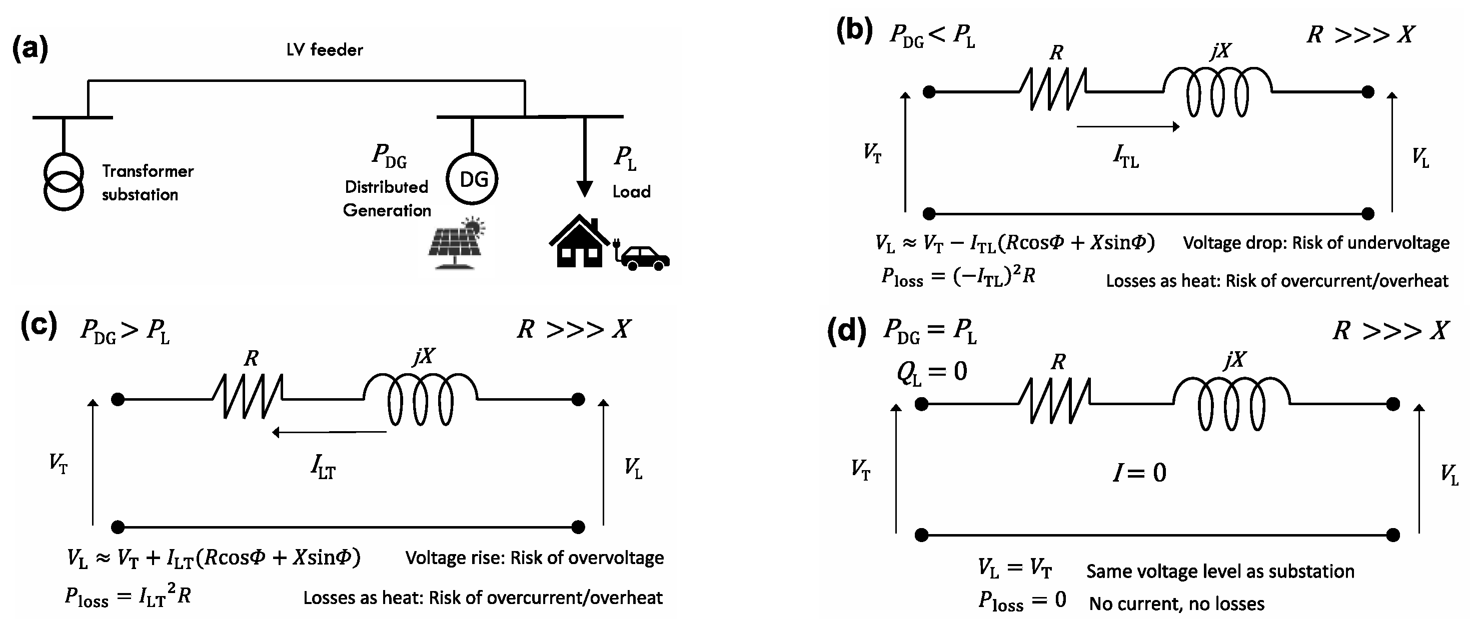
Figure 2.
V2G Concept [15].
Figure 2.
V2G Concept [15].
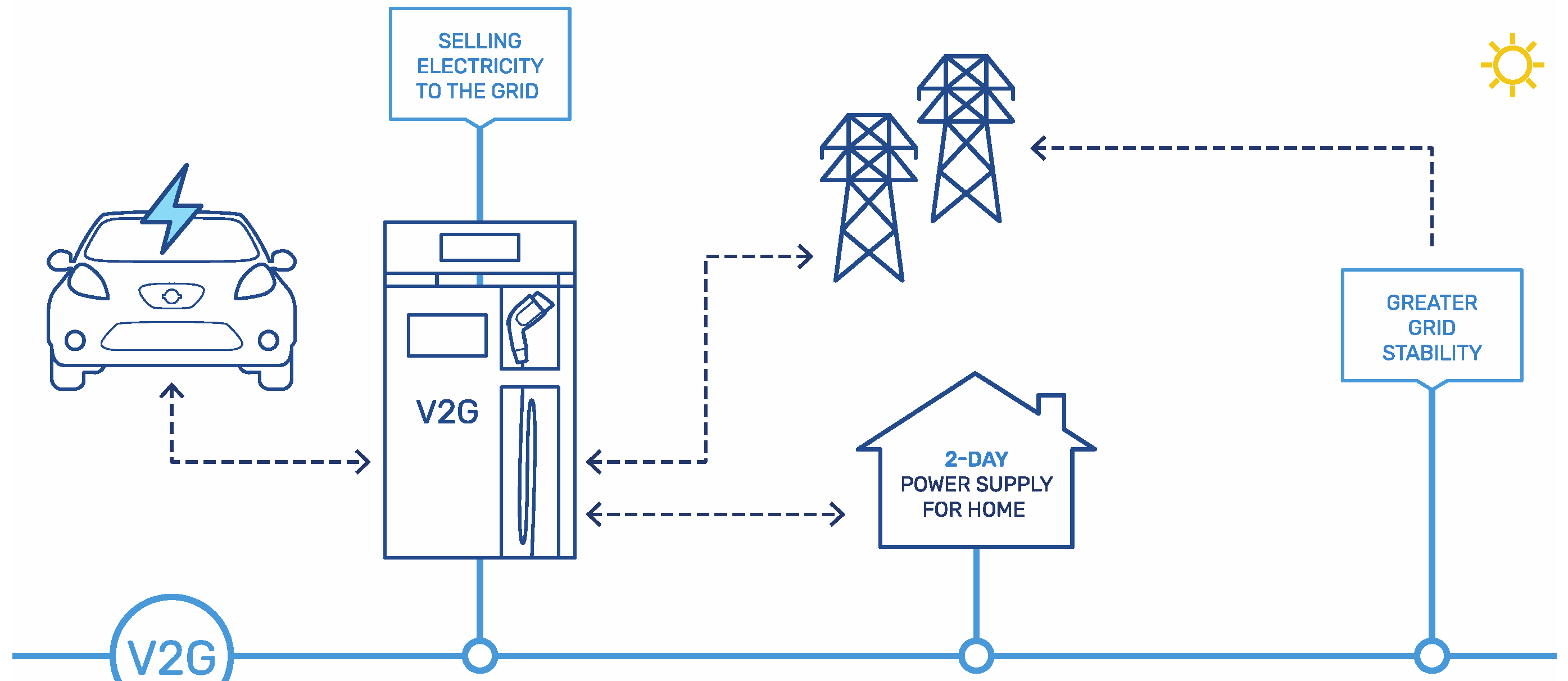
Figure 3.
Flowchart of the simulation.
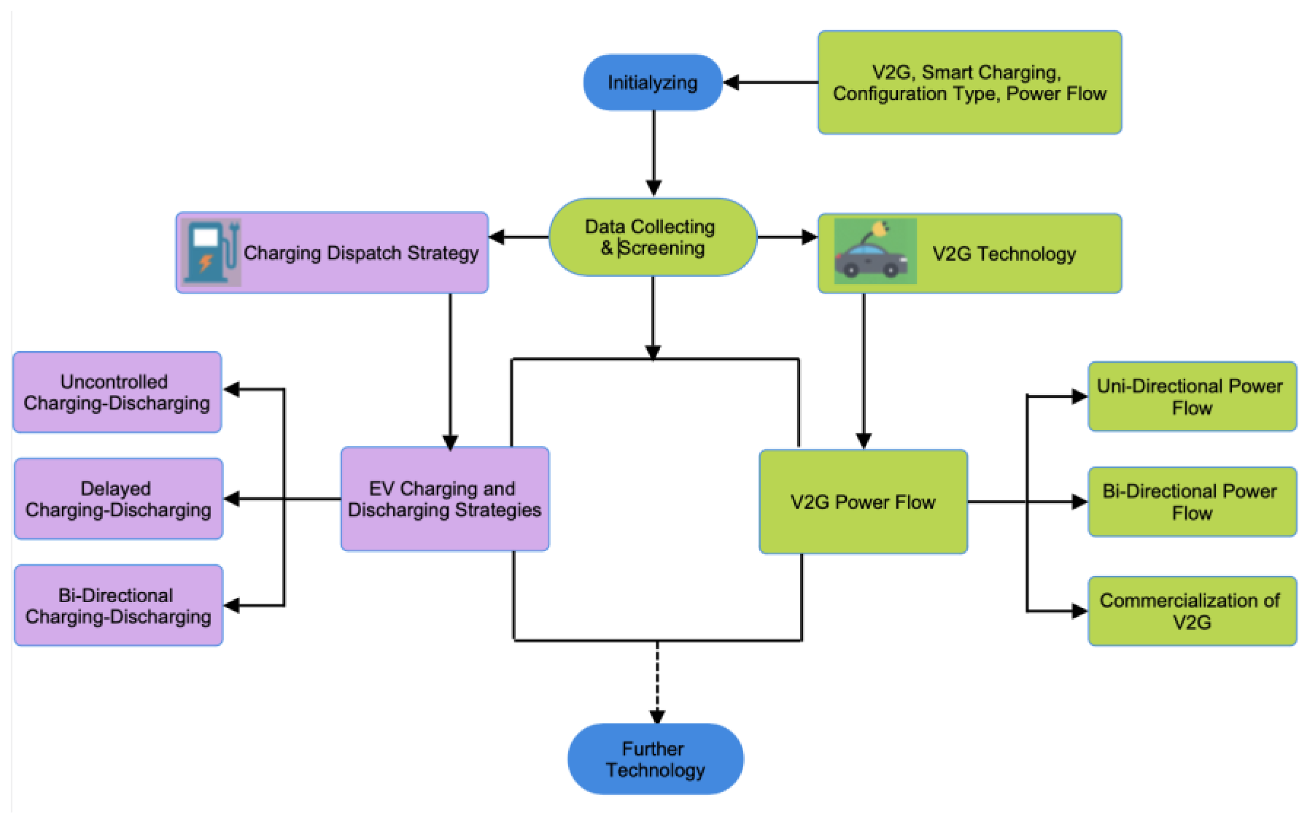
Figure 4.
Schemes of EV Charging Strategies.
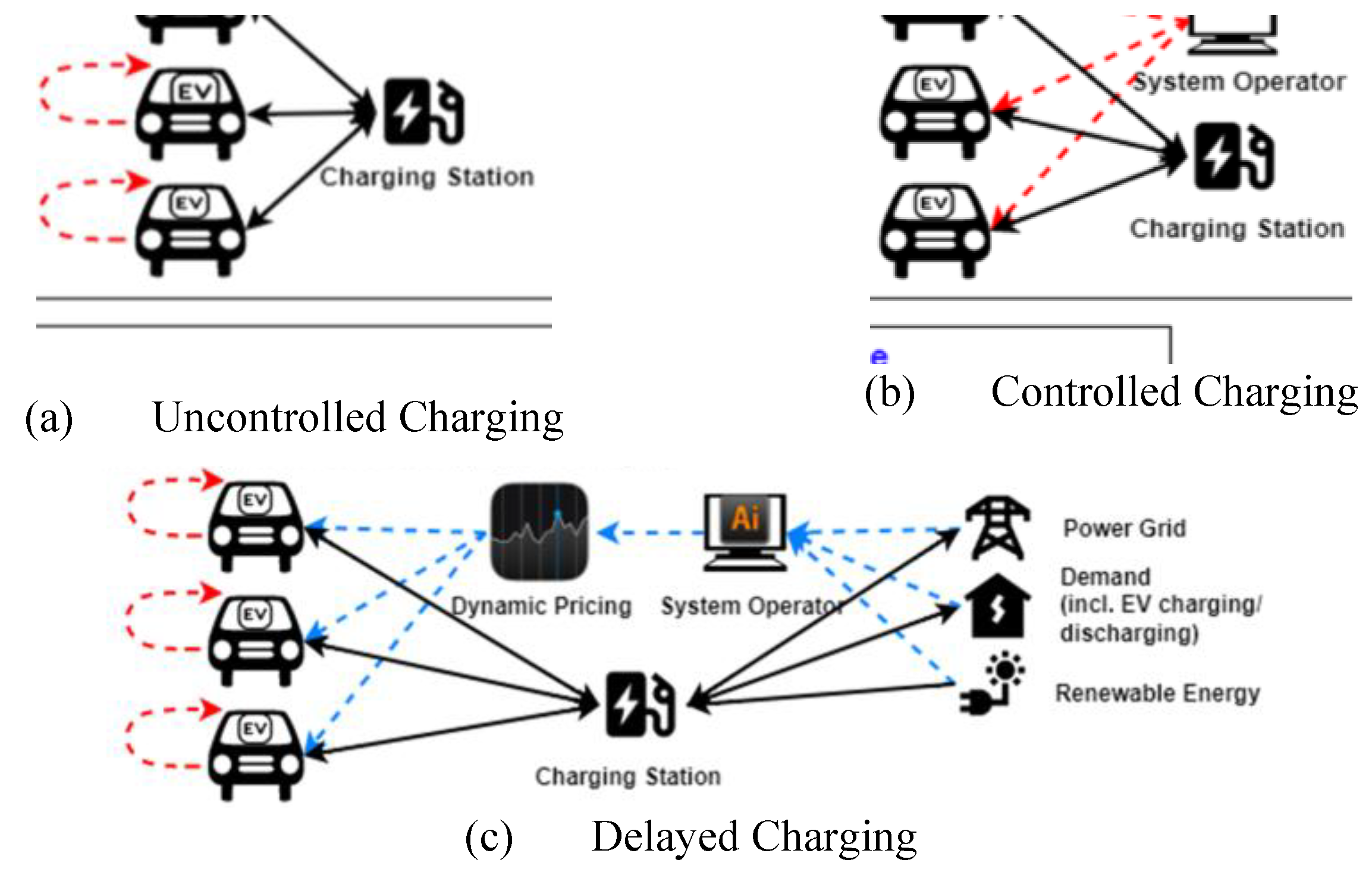
Figure 7.
I-V and P-V characteristic display.
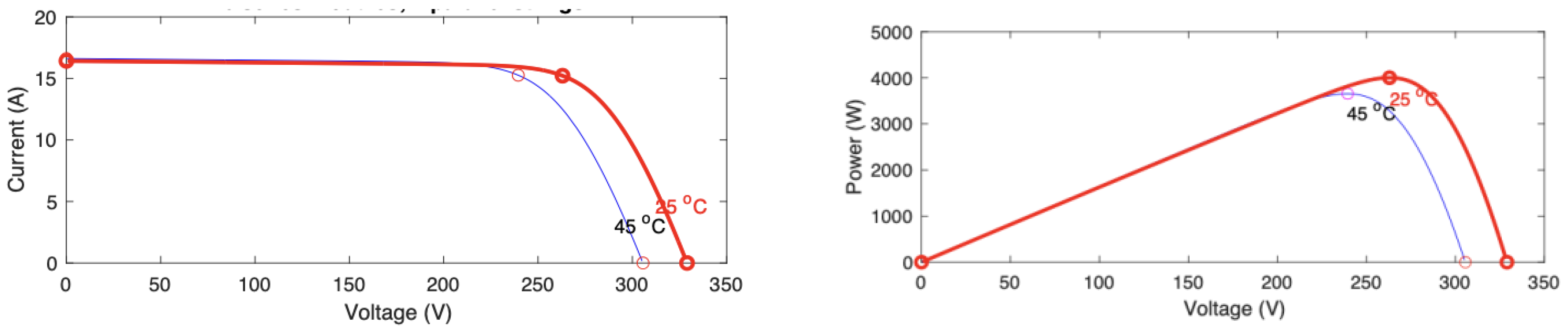
Figure 9.
Battery charge responses in controlled and uncontrolled strategy.
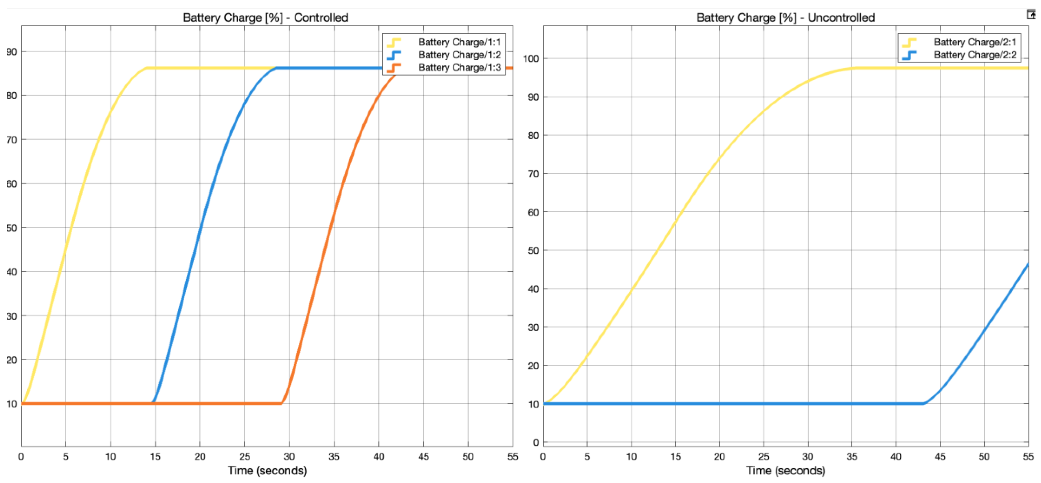
Figure 10.
Responses of powers, DC link voltage, and current of the proposed simulation.
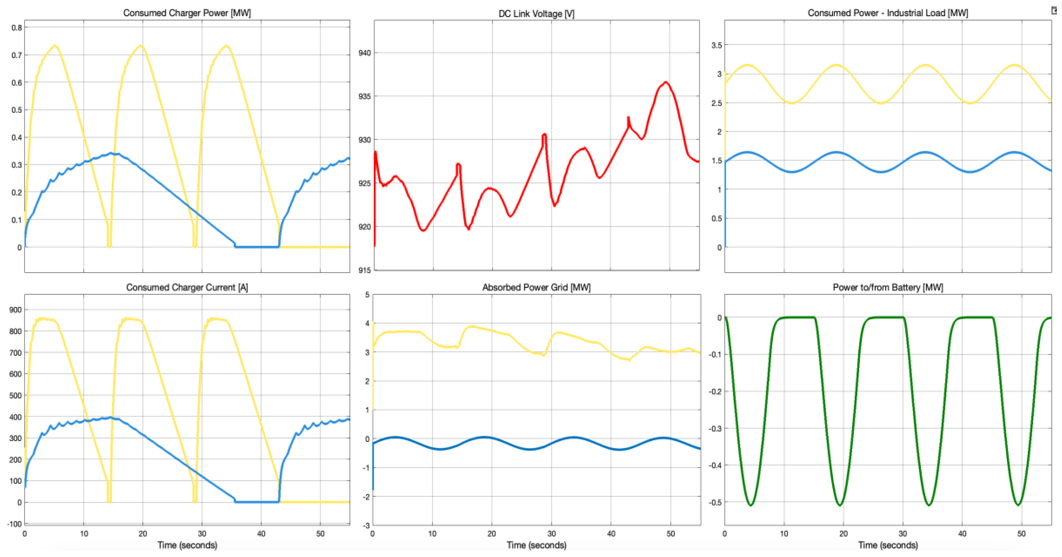
Figure 11.
V2G Grid Voltage and Current.
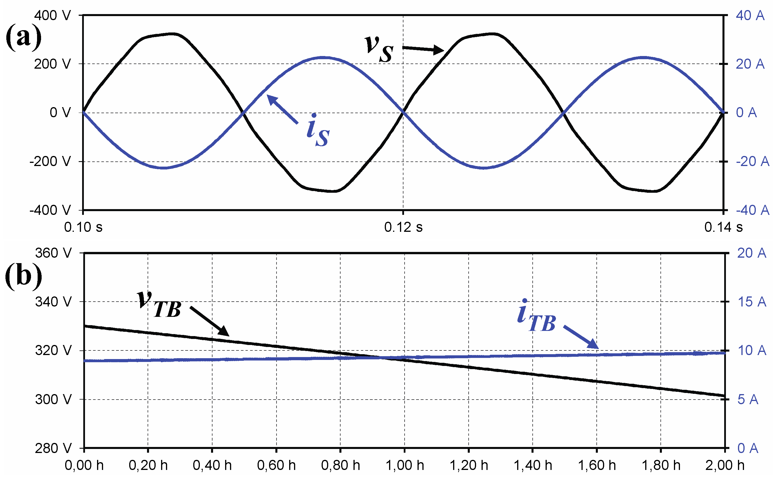
Figure 12.
V2G Grid Voltage and Current.
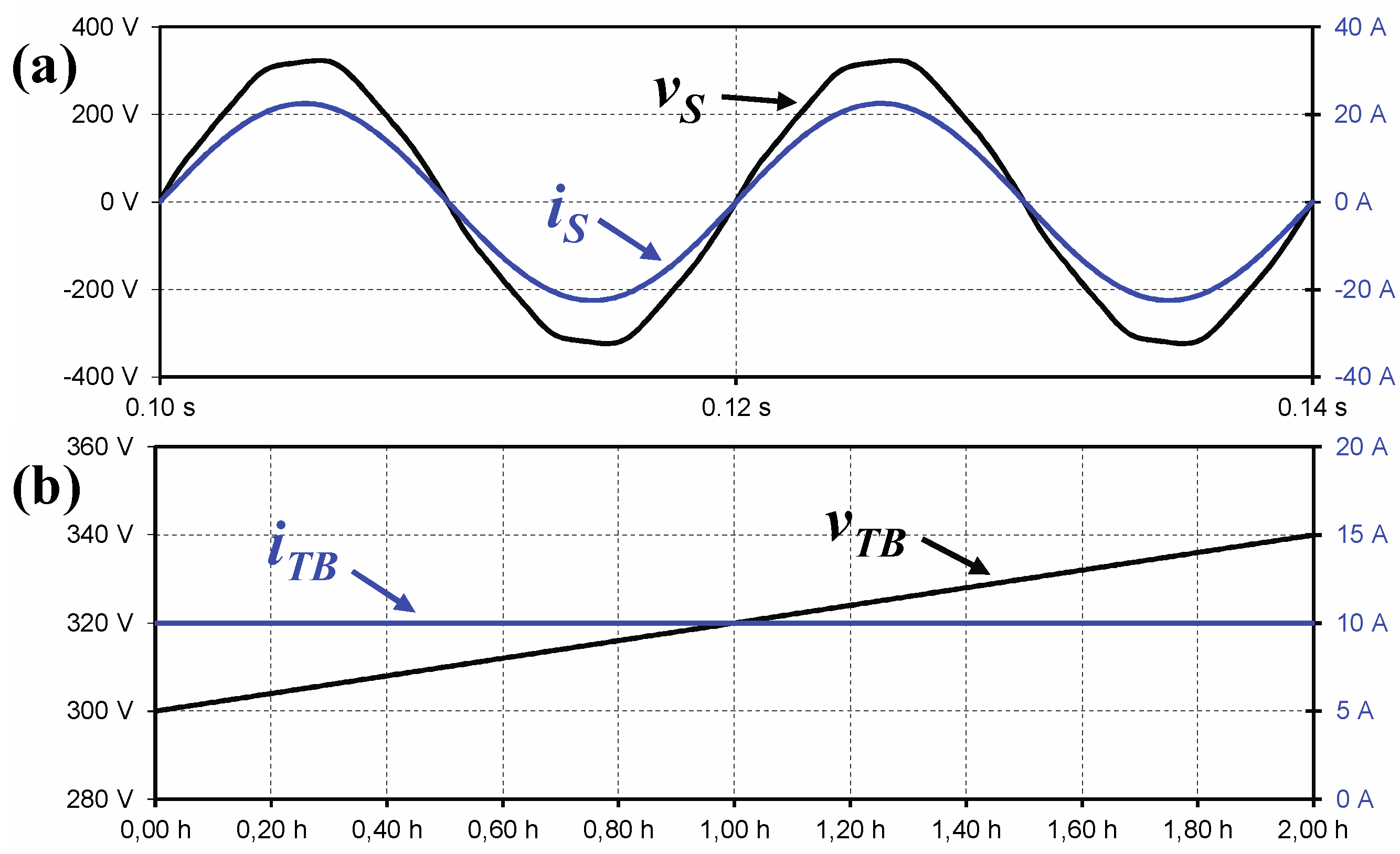

Table 1.
Simulation of charging station models’ specifications and conditions.
| Model No. 1 | Model No. 2 | |
| Configuration Type | Plug-in Vehicle | Battery Exchanging |
| Power Flow | Uni & Bi-directional | Uni-directional |
| Charging Dispatch | Uncontrolled & Bi-directional | Controlled & Delayed |
Table 2.
Summary of different EV charging and discharging dispatches.
| Dispatch | Advantages | Disadvantages |
| Uncontrolled | - Easy implementation - EV owners freely to make charging decisions - Convenience for EV owners |
- Add burden to power grids - Charging costs might be higher - Unmatched with the demand-side management system |
| Controlled | System operators freely to make decisions | EV owners have to cede control to the system operators |
| Delayed | Use monetary terms to encourage EV owners to participate in smart charging | Electricity pricing signals need to be accurate to be effective |
Disclaimer/Publisher’s Note: The statements, opinions and data contained in all publications are solely those of the individual author(s) and contributor(s) and not of MDPI and/or the editor(s). MDPI and/or the editor(s) disclaim responsibility for any injury to people or property resulting from any ideas, methods, instructions or products referred to in the content. |
© 2025 by the authors. Licensee MDPI, Basel, Switzerland. This article is an open access article distributed under the terms and conditions of the Creative Commons Attribution (CC BY) license (http://creativecommons.org/licenses/by/4.0/).
Copyright: This open access article is published under a Creative Commons CC BY 4.0 license, which permit the free download, distribution, and reuse, provided that the author and preprint are cited in any reuse.


