
Submitted:
06 January 2025
Posted:
07 January 2025
You are already at the latest version
Abstract
The development of liquid hydrogen storage systems is a key aspect for the enabling clean air transportation. However, safety analysis research for such systems is still limited. This paper presents the outcomes of a preliminary safety assessment applied to this new type of storage system, accounting for the hazards of hydrogen. The focus is on the implemented safety assessment methodology, which used to analyse the most critical features of the storage system. Based on the safety assessment, a set of safety recommendations concerning different subsystems of the liquid hydrogen storage system is proposed, which have been further reviewed by domain experts, identifying necessary mitigation actions. The presented approach has been proved to be suitable for identifying essential liquid hydrogen hazards and for providing systematic design recommendations for different subsystem areas.
Keywords:
Hydrogen storage
; Liquid hydrogen operation
; Novel system development
; Safety Management
1. Introduction
The aviation industry has recently witnessed a surge in efforts to develop liquid hydrogen (LH2) systems, placing a spotlight on the associated safety challenges. As the push for cleaner, more sustainable aviation fuel alternatives intensifies, LH2 has emerged as a promising candidate [1]. However, the unique properties of LH2, including its extremely low temperature and high volatility, necessitate rigorous safety considerations in its storage and handling [2].
Recent trials for LH2 storage have yielded mixed results. While some experiments have successfully demonstrated the feasibility of long-term storage, others have highlighted the complexities involved in maintaining the required cryogenic temperatures and managing boil-off rates [3,4,5]. These trials have underscored the need for innovative tank designs and advanced insulation technologies to meet the demanding requirements of aviation applications.
A recent analysis of cryogenic vessel incidents conducted by the OECD in 2023, reveals a declining trend in fatalities [6]. However, this positive development is accompanied by a concerning decrease in incident reporting and participation in safety studies. Moreover, the root causes of reported incidents remain limited in scope, potentially masking underlying issues [7]. Furthermore, existing cryogenic storage vessels have not been designed for use in aircraft, raising the question of how to translate learnings from these historical incidents to the aviation sector.
The present research was performed in the context of the composite conformal liquid hydrogen tank (COCOLIH2T) European project. This project aims to address the challenge of liquid hydrogen storage on board of aircraft by developing next-generation LH2 tanks with improved performance and safety characteristics. Specifically, the project targets ambitious goals for tank gravimetric efficiency, capacity, dormancy, venting rate, filling rate, and boil-off management. These objectives are complemented by strict dimensional and pressure constraints to ensure compatibility with aircraft systems. Within the COCOLIH2T project two prototypes will be produced, aiming to arrive at a technology readiness level (TRL) of 4. The goal of the safety analysis activities within the project was therefore two-fold: (1) to support the design of the prototype systems within the project, and (2) to identify what further technological development or safety features may be required to enable safe operation of future liquid hydrogen storage systems at TRL 9.
In the context of these technological advancements, safety assessment plays a critical role. Its primary objectives include:
- Identifying safety-critical load cases and operational scenarios for the concept tank.
- Assessing potential safety hazards posed by the tank to the aircraft and its environment, with particular emphasis on leakage and tank rupture scenarios.
- Modelling and analysing risk levels associated with identified safety hazards within relevant safety scenarios.
- Establishing risk acceptance criteria, proposing risk-reducing measures, and defining corresponding safety requirements.
The issue with the apparent low number of registered hazards for LH2 storage components is addressed in this work through the comprehensive definition and analysis of potential failure modes and their consequences. To achieve these goals, we have also conducted an extensive review of available knowledge sources, leveraging multiple databases and incident reports. This paper aims to identify and categorize the main causes of hazards in LH2 storage systems for use in aircraft, building upon previous work such as NASA’s historical studies on cryogenic systems [8] and other recent incident databases.
A key challenge in this work was conducting a safety analysis during the preliminary design phase, where few details of the system architecture had been defined. To address this, a new framework was developed. This paper proposes a methodology for the preliminary safety assessment of new LH2 storage systems, inspired by the ARP4761 standard for safety evaluations [9].
Furthermore, this paper seeks to disseminate the latest findings from recent studies on the safety of liquid hydrogen storage systems, contributing to the growing body of knowledge in this critical field. By combining historical data, recent experimental results, and advanced risk assessment techniques, we aim to provide a comprehensive overview of the safety landscape for LH2 tanks in aviation applications.
2. Materials and Methods
The safety assessment process outlined in this paper follows specific steps that are described in the following sections and summarized in Figure 1. First, the functions of the analysed system are defined following a technical review of previous liquid hydrogen storage implementations, and according to the requirement of the system being developed. These functions were systematically assessed for the physical effect in case of different forms or modes of failure in several operating conditions. This process, which is the core of the Functional Hazard Assessment (FHA) defined in Ref. [9], outputs a list of failure effects that may be hazardous for the people operating within the defined system, people leveraging the system, the system itself or the environment. For each of these failures, safety recommendations have been identified following the different hazard categories delineated for this specific system. These safety recommendation have been ranked based on the relative impact and frequency of the associated failures, which have been obtained respectively trough the assessed hazards severities and the hazard database analysis. Based on the recommendation list, relevant design experts were interviewed to collect their feedback and identify further actions towards a higher TRL design.
2.1. Functions of the Liquid Hydrogen Fuel Storage System
Defining the functions of a liquid hydrogen fuel storage system for aviation requires comprehensive knowledge of hydrogen behaviour, working principles of existing ground and vehicle storage systems, and the specific requirements for commercial aviation applications. An extensive review of literature and technical manuals was conducted to establish this foundation. References [10,11,12,13] provide insights into the behaviour of hydrogen, particularly in its liquid state. Significant descriptions of involved technologies, implementation within aviation and working principles are detailed in references [14,15,16], while a recent experimental trial testing hardware within this scope is proposed in Ref. [17]. Lastly, safe and economic viable refuelling methods and strategies are delineated in Refs. [18,19,20].
Liquid hydrogen tanks for aircraft must meet stringent requirements to ensure safety and efficiency. These tanks need to be exceptionally well-insulated to maintain the hydrogen at cryogenic temperatures of around -253°C (-423°F). Recent design implementations [21] involve double-walled tanks with vacuum based insulation, as this concept leads to longer storage periods while keeping the system mass reasonable, so that the obtained gravimetric efficiency can be high enough to make this fuel system usable in a commercial aircraft, as expected also in Ref. [1]. The LH2 fuel is subject to evaporation, which is referred to as fuel boil-off and which has to be addressed by engineers for both normal operations and abnormal conditions, requiring venting systems and potentially fuel re-circulation mechanisms during parking of the aircraft. Within this scope, material design choices for the tank play a major role in balancing risks and performance.
Additionally, the tank placement within the aircraft has to conform to both energetic and safety considerations. Energetically, the surface to volume ratio has to be kept as low as possible to reduce the heat leak. For safety the tank itself must be kept away from collisions and possible debris penetration. Within the COCOLIH2T project, the tail area has been selected for this scope, as it is free from frontal impacts and rotor blade rupture penetration. Given the low operating pressure of cryogenic storage tanks, it was possible to design a tank that can conform to the fuselage taper, enabling more efficient use of the available volume.
A simplified representation of a such multi-walled tank with its interfaces is shown in Figure 2. Given the literature on developed LH2 storage systems, the main functions identified for these systems are:
- Contain fuel and maintain its thermodynamic state.
- Enable fuel transfer.
- Ensure system monitoring and control.
- Provide protection against natural and induced environment.
The first function class describes the core responsibilities within the fuel storage domain, incorporating passive and active features to maintain the necessary fuel thermodynamic state and ensuring it remains securely contained and does not reach unintended areas. Functions 2 and 3 serve as interfaces with other systems and the external environment, indicating their roles in the exchange of respectively matter and information. Also in this case, some of the function are directly related to the expected behaviour of a fuel storage, while others are necessary for the safe operation of a liquid hydrogen system. Functions of tier 4 include passive measures to prevent primary hazards, and have a cascade effect on each design and operational choice. These functions have been expanded to their sub-functions, which are listed in Figure 3.
This description in terms of system functionality allows to step back from the initial design, material, and component choices which serve the same purposes but might hinder a coherent development of the system architecture as a whole. Ideally none of these functions should be failing for a safe functioning of the tank. However, as failure may occur, it is essential to study possible functional failures and their effects under the various expected operational environments and configurations.
2.1.1. Operational Configurations and Environments
For the sake of this preliminary safety assessment, different configurations or conditions have been considered. These are applicable both for the demonstrator being built in the COCOLIH2T project at a low TRL and for the mature storage system envisioned at higher TRLs. The selected configuration modes for this study are the following:
- Configuration mode 0 – Manufacturing
- Configuration mode 1 – Handling
- Configuration mode 2 – Fuelling
- Configuration mode 3 – Flight
- Configuration mode 4 – Dormancy
- Configuration mode 5 – Maintenance
In the case of demonstrator operation, the flight configuration is considered as "test" mode. Each of these configurations will impose different functional demands on the storage system, which will be met through the combined subsystems’ efforts. For example, fuelling relies on the function "Ensure fuel transfer" (Ref.2) but also on the function "Provide information" (Ref.3). Furthermore, hazardous situations may occur when the required system functions are not fulfilled as expected. It is important to identify and study such situations systematically, considering also the type of environment the storage system may encounter. The identified operational modes representing different environmental types are listed below:
- Environment mode 0 – Normal operation
- Environment mode 1 – Fire
- Environment mode 2 – Power loss
- Environment mode 3 – Saturated gas environment
- Environment mode 4 – Mechanical contact
- Environment mode 5 – Arc discharge
At this point, with the functions of the system being defined together with its operational configurations within the different possible environments, the hazards stemming from the failure of these functions can be assessed. The systematic procedure is described in the next section.
2.2. Systematic Collection of Failures
The systematic evaluation of the functional failures was conducted by a core team of safety analysts, and supplemented by gathering feedback from other experts involved in the system design. The methodology applied to determine relevant system failures is described in this section. Failure and hazard identification was conducted based on the knowledge of the working principles of the system under analysis and of the behaviour of the interacting medium. Each identified failure corresponds to a hazard or multiple hazards with associated risk level. The risk is determined by the combination of the hazard frequency and impact, quantifying the overall posed threat. Impact measures the severity of the outcome, while frequency measures how often the event occurs.
For this preliminary safety assessment, reliable information about impact and frequency was not publicly available. In particular, while the consulted databases allow one to identify how often particular types of incidents occur, there are typically no statistics provided describing how often certain operations were conducted without incident. This makes it impossible to accurately calculate the frequency measure for most identified hazards. For this reason, the risk was determined using two substitute parameters denoted as incidence and relevance, which represent respectively the frequency and impact. The hazard assessment was performed to determine the relevance parameter, while the hazard database analysis was used to determine the incidence parameter. A more detailed description of these parameters is provided in the next sections.
For each functional failure and hazard one or more mitigation actions have been defined within the assessment process. These have been identified as "Safety Recommendations" and their risk level is determined with the parameters introduced above, with the objective of ranking these actions. In some cases, the same safety recommendation was identified for different functional hazards.
2.2.1. Functional Hazard Assessment
The FHA methodology, initially described in SAE ARP 4761 [9] is a safety analysis process used in aerospace, automotive, and other safety-critical industries. It helps identify potential hazards associated with system functions and assess their possible consequences on the overall system’s operation. It has been found to be an effective tool to mitigate risks early in the development process by decoupling functions from components, allowing engineers to focus on the inherent safety of system functions independently of the specific hardware or software implementations. This separation enables a more flexible and thorough analysis of potential hazards, ensuring that safety considerations are integrated into the design from the beginning, regardless of the specific components used. For the sake of this analysis EUROCONTROL’s methodology [22] was used as a guidance manual for hazard identification, as described below.
For each function of the tank system within the identified list, each failure effect from the list below was systematically investigated in the different configurations, operational environments and scenarios provided in the section above. Failure modes arising from either internal factors or external events have been considered, e.g. respectively component degradation and collision damage. The functional failure modes accounted for are the following:
- Loss of function
- Partial loss of function
- Function provided when not needed
- Unannounced loss of function
- Malfunction
This approach, when applied systematically, would identify thousands of failures if accounting for all the possible combinations. Additionally, single failures may lead to multiple hazards that have to be accounted separately, as different actions may be needed for mitigation. During this assessment the failures and consequent hazards have been identified systematically in order to avoid missing minor or critical cases. During the analysis of each failure mode, the associated hazard effects were described based on the understanding of hydrogen behaviour, which aids in determining the severity of the effects. Each identified functional hazard was then assigned a specific index value, with a detailed description outlining the failure effects on functioning, people, property, and environment. Hazards are subsequently classified by severity, based on their potential effects, using standardized criteria reported in Table 1. For calculating the relevance of these hazard a weight value WFHA has been assigned corresponding to the severity of the failure effect. Engineering judgment was applied to determine the criticality level of the hazard resulting from the evaluated failure effect.
During this process, one or more design requirements or actions to mitigate each identified hazard were suggested, where these might be classified in three main categories: Design, Operational, and Barrier protection. These criteria formed the basis for the safety recommendations, and an index was assigned to each of them to permit cross linking. Also, this permitted to connect different hazards to the same applicable safety recommendation.
2.2.2. Hazard Database Analysis
The hazard database analysis aims to identify failure rates of the functions in the considered hydrogen storage system. Incident databases serve as a critical resource for learning from past operational and design errors, despite their limitations such as self-reporting biases and incomplete system descriptions. The data collection effort, conducted towards the end of 2023, involved the integration of information from multiple incident databases into a unified COCOLIH2T safety database, excluding some sources due to access restrictions or data inapplicability. Collecting information from incident/accident databases is a practice, which was already used in the Regulation Codes and Standards (RCS) for hydrogen [23]. The most relevant historical reference is the NASA review of accidents and incidents [8], which was also used within the ANSI/AIAA Guide to Safety of Hydrogen and Hydrogen Systems [24]. This database provides failure rates as a percentage of total failures, with the two most critical (over 10% of failures) represented by valve malfunction and leak from connection. Furthermore, this study concluded that human factors played a substantial role, with 87% of failures involving operational, procedural, design, or planning errors. During the following years, several new hydrogen systems have been developed and implemented. However, the number of incidents and accidents reported in the databases has shown a decrease, with only a handful of component failures directly relatable to liquid hydrogen storage [6]. This was explained by more system maturity and increased private development [7,25,26].
Since publicly available databases with component failure rates for liquid hydrogen storage systems are either insufficient or not representative enough, assessing the real failure frequency of incidents remains challenging. To address this issue, the failure rates of components or subsystems found on publicly available databases performing similar functions to the ones under assessment were evaluated. Identified failing components or subsystems have been linked to their related system functions introduced in Section 2.1 based on a technical judgment. Some were not directly relatable to the functional failures of the system under consideration, so they were discarded.
The databases leveraged for this assessment were the following: the NASA Public Lessons Learned System (LLIS) containing 67 hydrogen-related incidents [27] among the other reported events; the Pacific Northwest National Laboratory’s Hydrogen Tools (H2TOOLS) Portal offering 223 lessons learned directly related to hydrogen operations [28]; and the European Hydrogen Incidents and Accidents Database (HIAD), updated to September 2023, including 712 hydrogen-related incidents [29]. This last database was the most valuable as good quality descriptions were reported for more than half of the entries. A report about this database is provided by Melideo and Wen [30], while Ref. [25] offers an overview of the features of latest version. According to the HIAD reference entries, only 5 of the database records come from the already included H2tools database, while the other entries are derived from various sources including scientific articles, news reports, self-reported incidents, and incidents reported by other organisations such as OSHA (Occupational Safety and Health Administration), ARIA (Analysis, Research, and Information on Accidents), eMARS (Major Accident Reporting System), and other databases, regulatory and safety bodies overseeing industrial incidents and occupational safety.
The scraped and collated database entries resulted in approximately 1000 hydrogen-related incidents, each represented by several attributes such as hazard index, source reference, failure title, description, contributing factors, severity. The severity of incidents was classified based on hydrogen release outcomes, namely: Hydrogen release and ignition, Unignited Hydrogen release, No Hydrogen release. This information was directly available in some databases, while it had to be figured out from the event description from the others. Still, for the matter of determining the functional failure frequency, this information was not employed. A justification for this is provided with the result of the hazard database analysis reported in Section 3.1, and refers to the fact that regardless of the reported severity (which may depend on how quickly the incident was responded to), each entry may have evolved from the identified failure condition and should therefore be given equal weight.
Once the entries were assembled in one place, the analysis consisted in reading the event description, lessons learned, or attributed incident cause, in order to identify what went wrong and if that was attributable to the failing of one of the function defined in Section 2.1. This was not always possible, for example in the case that the incident was related to hydrogen only because it was the result of a spontaneous formation (as it might happen in a chemical process, waste management, or battery related context) or the event involved was completely unrelated. Sometimes the event description did not provide sufficient information to identify the cause, or no incident was reported at all. In these cases, the function reference attribution was not performed and a not applicable index was assigned.
For all the other entries, the incidents from the databases were mapped to the functions of the fuel storage system in an iterative manner. This approach, while improving and establishing the identified functional classification, ultimately highlights the functions most frequently affected by failures. In the next section, a method to bring this information forward to the safety recommendations is proposed.
2.2.3. Safety Recommendations
After the assessment of the functional failures and the analysis of the hazard database incidents, the two components of the risk index can be determined. As introduced before, these two components are referenced in this framework as relevance and incidence indexes and they are calculated for each Safety Recommendation j so that the resulting risk can be then calculated as their product.
Each safety recommendation addresses one or multiple functional failures, which have a hazard severity weight assigned, as described in Section 2.2.1. The relevance of the Safety Recommendation j is determined by averaging the hazard severity weights over the n hazards related to that safety recommendation.
A similar operation is now performed for the second component of risk, that is the frequency related parameter, represented in our assessment framework by the incidence parameter. Again, each Safety Recommendation j is related to n functional hazards, stemming from the initially defined list of system functions. For each of these system functions a number of k hazard database entries were identified during the analysis described in Section 2.2.2. For each function t the number of related hazard database events was counted, obtaining the failure occurrence (FO) parameter.
Since the number of occurrences varies significantly among the different functions, a normalization is applied using a logarithmic function followed by a discretization function with the normalization rules provided in Table 2. These rules were chosen to linearize the distance between low occurring events and events reported several times, thus obtaining a range comparable with the relevance parameter.
At this point the normalized FOs assigned to the functions are related forward to the safety recommendations. Each normalized FO is directly passed on to the related functional hazards, with the simplifying hypothesis that each failure stemming from the same function has the same occurrence. Again, each safety recommendation j addresses one or multiple n functional failures, and also here an average of these related normalized FO indexes was calculated for each safety recommendation, obtaining the incidence parameter.
This approach provides a quantifiable metric that reflects the potential criticality of each recommendation related hazard. By ranking the safety recommendations based on their risk factors, organisations can prioritize their efforts, ensuring that the most critical and high-risk areas are addressed first. This method not only optimizes resource allocation but also enhances overall safety outcomes by systematically lowering hazard levels in the areas that pose the greatest threats.
3. Results and Discussion
In this section, we present the results of the preliminary safety assessment conducted using the proposed methodology. Specifically, the most critical hazards, the analysed failure frequencies and the consequent safety recommendations are discussed.
The complete list of identified liquid hydrogen storage system functions, the systematically assessed failures and the resulting assessed hazard criticality values, the obtained FO values from the hazard database analysis, and the following safety recommendation list are provided in the supporting material for this paper. Data is provided in a tabular format which streamline the preliminary safety process methodology proposed in this paper.
Hazard database entries are reported in a reduced format with respect to the original source, while maintaining the reference, event summary, lesson learned and severity data fields. Thus it is possible to understand the relation between the event description and the selected failing storage system functions, in order to be able to reproduce this framework to another new system. Also, by filtering through the function index, a subsystem developer can understand what go can wrong in their relevant areas and prevent these failures and hazards accordingly. Still, it’s important to note that the content of the underlying hazard databases is continuously updated, so analysts should download the latest version from the sources to conduct new analyses.
3.1. Main Hazards in LH2 Storage Systems
To assess the hazards associated with a liquid hydrogen fuel storage system for aviation, it is first essential to examine the potential consequences of improper fuel management. This is followed by a presentation of the hazard classifications derived from the FHA process, which outlines key risk domains and provides a perception of the severity levels involved. Finally, the analysis of the hazard database will provide insights into the likelihood of these specific hazards.
A thorough understanding of hydrogen thermodynamic behaviour is essential for accurately assessing the hazards associated with hydrogen within an LH2 system. This has been described and modelled broadly in publications [11,18] and manuals [10,12]. Notably, hazards and risks associated with its release might vary significantly, depending on the system [2] and the hydrogen state [31]. In particular, it is possible to distinguish between the following cases:
- Low flow rate release: This is usually caused by small leaks or significant permeation. It leads to a small release of gaseous hydrogen that may result in asphyxiation hazard. Combustion may occur if the mixing ratio with air exceeds a critical level called lower flammability limit, which is quite low, being around 4-7 vol%H2 depending on temperature, and an ignition source is present, being established at an energy level of 0.02 mJ, requiring just a small electrostatic discharge [13]. The resulting flame has a low emissivity, making it non visible and difficult to recognize. The consequence of hydrogen accumulation without initial ignition are discussed later in the explosion paragraph, introducing the need of ventilation.
- High flow rate release: This occurs when hydrogen is rapidly discharged trough a breach in the equipment in a focused stream, which can be either gaseous or in a two-phase state. Aside from the risks arising from direct contact with the stream, which may cause cutting blasts, the main hazard associated with jet releases is the potential for deflagration, which refers to the accelerated propagation of flames and can lead to highly dangerous pressure waves.
- Pool Vaporization: This type of hazard involves the spillage of liquid hydrogen, which then transitions to a gaseous state and accumulates [32]. The primary risk is an increased likelihood of combustion due to the accumulation of hydrogen gas, followed by severe cryo-burns if the fluid contacts skin.
- Explosions: This scenario might occur as a result of different causes, involving different physics. First, it is identified as boiling liquid expanding vapour explosion (BLEVE) the explosion of liquefied gas vessels [33]. This happens following a catastrophic rupture of the vessel from other causes, and the outcome depends on the initial thermodynamic state. Ustolin et al. [34] modelled this phenomenon for LH2 storage systems and validated their results with prior experiments from literature. The study concluded that, in the case of insulated vessels, means of rapid discharge or venting of the hydrogen need to be put in place, employing safety features such as pressure relief devices (PRD). Secondly, explosion could occur from delayed ignition of mixtures of gaseous hydrogen with air. The potential for explosion in this case is concerning from the rapid combustion which results in the release of pressure waves, leading to design choices which avoid confinement of gaseous releases in areas such as dead ends and ceilings. The risk associated with explosive releases is severe, with the potential for significant damage to the surrounding area [35].
Analysis of the incidents shows that hydrogen release can result from various factors, often occurring simultaneously rather than in isolation. In some cases, individual failures may not immediately lead to hydrogen release; however, without a fail-safe design that restores the system to a secure state, these failures may go unnoticed, potentially escalating into dangerous situations. Therefore, prompt action is essential following any failure, but first those must be promptly identified and analysed.
With this in mind, the hazards coming from the functional failures obtained during the systematic FHA process introduced in Section 2.2.1 have been further grouped and classified. The following paragraphs summarize the results, highlighting the various risks involved. Alternatively, these categories can be viewed as distinct action areas requiring focused attention. Figure 4 presents the frequency counts for each category, showing which domains exhibit the greatest diversification of threats and therefore demand more intensive assessment efforts. The hazards identified in this preliminary safety assessment are organized into the following five main categories:
C001 - Permeation through containing walls: This hazard involves the gradual leakage of hydrogen through the containing material due to molecular diffusion or, more rapidly, through small defects or voids. These micrometre size features are more common in composite laminates [36,37,38], but adoption of composites for liquid hydrogen vessels is still investigated for the potential of better performance [39,40]. Although this type of release is typically slow and does not immediately pose a significant danger, because the rate at which flammable concentrations is reached is low, still it requires careful management. The primary risk associated with this type of release is the potential for loss of performance and the accumulation of hydrogen in unexpected areas. To mitigate this risk, it is essential to implement effective ventilation or recirculation systems while ensuring that the hydrogen permeation through the tank skin and the rest of the equipment remains within permissible levels during the service life of the vessel.
C002 - Hydrogen release through openings: This category refers to the rapid release of hydrogen that can occur when the interface between components fails or there is a pass-through fracture in the equipment. Such breaches lead to a rapid and violent release of hydrogen, which poses several risks depending on the reached areas. Therefore, it is crucial to ensure that component connections are robust and secure, preventing unforeseen vibrations and contacts. Mitigation strategies should focus on designing components with high reliability and ensuring proper maintenance and inspection routines.
C003 - Hazards related to fuel management operations: This class covers risks associated with the operational procedures involved in managing hydrogen fuel. These hazards can arise from both human errors and mismanagement of unexpected circumstances from automated systems. The potential risks from improper handling of fuel and operational mishaps could lead to unsafe conditions, hydrogen release, and damage to the storage system. To address these risks, it is important to establish and adhere to operational protocols based on hydrogen thermodynamics, while also being able to adjust them according to the current state of the tank.
C004 - Hydrogen incompatibility, design error: Hazards in this category are due to the use of materials or designs that are incompatible with hydrogen and its thermodynamic behaviour. Such incompatibilities lead to material degradations, which can result in unexpected hazardous circumstances. To prevent these risks, it is crucial to follow established design guidelines and ensure that all materials used are suitable for hydrogen service. Materials with reduced risk of embrittlement are provided in Ref. [41], while the RCS introduced in the next section will provide guidance for safe equipment design, such as selecting the correct pipe diameters and venting system.
C005 - Hazards unrelated to hydrogen release: This category includes risks that are not directly associated with the release of hydrogen but are still relevant to the overall safety of the hydrogen tank system, including unplanned deteriorations of materials or departure from intended system behaviour arising from external events. These can include issues like component malfunctions, sensor failures, unplanned workload or operators bypassing guidelines, which will eventually affect the system performance and safety. Effective mitigation requires addressing those deficiencies, whether they occur from normal use or accidentally, in order to ensure the reliability of the whole system.
Hazards from categories C002, C004 are those with the overall highest impact and often catastrophic consequences and thus require particular attention, also because they can occur abruptly if not monitored and managed properly. These are followed by the hazards of category C003, which still pose a significant threat, given people might be involved or the surrounding environment might be contaminated. The impact of categories C001 and C005 should still not be neglected, as they may hider the functionality of the overall system, leading to safety and performance deteriorations.
At this point it is fundamental to understand which of those scenarios are more frequent, thus requiring more attention. For this purpose incident and accident databases were used, which were developed to serve as a tool for providing recommendations during the development of new systems that are subject to similar hazards. Relevant lessons learned and statistics obtained from such databases regarding hydrogen operations have already been reported in recent studies [26]. In the context of this preliminary safety assessment, the available information was utilized to determine the frequency of these hazards by correlating incidents from the databases with the identified system functions.
Figure 5 presents the absolute count for the database incident entries associated with the different system functions, split for the different hazard database severity indexes introduced in Section 2.2.2. It can be observed that for the same failing function, the incidents reported more are always those with higher severity. This result might be biased by how and when these incidents are detected and subsequently reported on publicly available databases, giving more attention to perceivable failures, or failures that led to significant consequences. For this reason, and for the matter of assessing the incidence of these functional failures, the weight chosen for the different incident severities is the same, while unclear entries and entries not related to the system under analysis were excluded.
The result of this hydrogen hazard database analysis applied to the storage system points out that the most failing functions are related to the vessel and piping integrity, the stability of the mating interfaces of the fuel lines, the ability of providing a reliable filling operation, and the predictability of the fuel dumping and pressure release technologies. Many incidents have been caused by vehicle collisions and impacts, but their average severity was lower here due to a safe design. Special attention must be given also to the setup of maintenance operations and the ability to fully remove hydrogen through purging processes must be taken into account. Failure to monitor hydrogen concentration and ensure proper system operation has been identified as the cause of several fatalities.
Regarding the functions of the fourth tier, particularly in terms of preventing hydrogen accumulation and ignition sources, these functions were selected based on the absence of other functional failures in systems similar to hydrogen storage. In fact, in most of other incidents, hydrogen accumulation and/or ignition were present and contributed to the hazard. However, the primary cause in those cases was a failure of another function as reported, which led to the release of hydrogen. While these safety functions are of complementary importance, they should not be overlooked. Some incidents in this domain originated from not selecting inert materials, which at some point deteriorated further leading to exposure of electrical contacts, accumulation of hydrogen in unintended areas, or lightning directly striking the hydrogen storage vessel.
All of these factors need to be accounted and addressed seamlessly, next section provides some recommendations maturated during this assessment for developing a safe a liquid hydrogen storage.
3.2. Safety Recommendations for LH2 Storage Systems
The list of safety recommendations with the highest risk level obtained during the hazard assessment is reported in Table 3 to give the reader a representation of the types of requirements needed for the development of a safe LH2 fuel storage system, while the remaining recommendations are provided in the supporting material. By implementing these requirements, it is possible to mitigate the identified risks associated with hydrogen tank systems and enhance the overall safety.
The identified safety recommendations focus on ensuring operational safety, system integrity, and minimizing risks during development and testing. First, it is essential to ensure that the tank structure is not subject to hydrogen leakage under cryogenic conditions. This can be achieved by conducting leak tests on structural elements, components and fittings under the operating conditions, ensuring that leaks are cleared and permeation remains below a critical threshold. To safeguard against leaks from fitting failures, factors such as improper local pressure estimates, vibration, and surface preparation should be managed. All components should be securely attached with additional support to prevent excessive displacements.
Some safety recommendations refer directly to RCS where exhaustive description on how to implement those criteria are provided, for example S014 refers to the ammunition and explosive safety standard [42] from the United States Department of Defence (DOD) where guidelines on how to avoid ignition sources are provided. Recommendation S009 makes reference to the compressed gas association (CGA) standardisation organisation, which provides calculation tools for vent lines in the Standard for Hydrogen Vent Systems [43]. As a general rule, in order to develop components which are able to fulfil their function safely, designers should always consult and follow the relevant RCS, with a special attention to Refs. [24,41,42,43,44,45,46,47,48,49], while a more extended list is provided within the supporting material of this paper.
The identified safety recommendations, when implemented, help ensure the safety, reliability, and integrity of the LH2 storage systems throughout their development and testing phases. Those can be aggregated in the following groups:
- Prevent leaks: Implement measures to minimize the risk of hydrogen leaks from equipment and piping.
- Prevent accumulation of hydrogen: Ensure proper ventilation to avoid the build-up of hydrogen, reducing the risk of explosive mixtures through effective ventilation systems. Ensure potential releases of hydrogen do not reach regions occupied by people.
- Prevent ignition sources: Eliminate or control potential ignition sources to prevent fires or explosions in hydrogen-rich environments.
- Prevent component failures: Use materials that are resistant to hydrogen embrittlement and select components that are reliable, ensure that system and components are robust and regularly inspected.
- Follow design guidelines: Ensure design is in accordance with latest regulations codes and standards (RCS), provide third party review of the design choices.
- Ensure effective operational protocols: Follow stringent operational guidelines, and implement rigorous training to reduce human error and ensure safe operations, establish evacuation plans.
- Ensure fail safe capabilities: Provide that the system can revert to a safe condition in case of accidental damage, allowing for hydrogen to be released in a safe manner in the most extreme situation.
- Continuous monitoring and detection alarms: Perform regular monitoring and inspections for the health condition of the vessel to address potential failures promptly, monitor for hydrogen leaks, providing evacuation alarms.
In the context of demonstrator operations, which involves various scenarios of human interaction, it is crucial to prioritize personnel safety by implementing adequate protective measures during the operations, such as the definition of unsafe zones established around the system and with the usage of remote-controlled shut-off valves for emergencies where a physical proximity to the system can be deemed as hazardous. Remote defueling systems should be implemented to allow for safe fuel removal in emergency conditions, and the testing operations must be conducted in a well-ventilated environment. Integrating technologies like structural health monitoring and vacuum sampling can improve the early detection of potential failures.
Redundancy in safety features is deemed as essential during this design development phase. Implementing fail-safe designs, such as backup systems or parallel safety features, can significantly reduce risks related to hydrogen release or structural damage. Determining the necessary level of redundancy requires a thorough analysis of the proposed system architecture and should be addressed in future design efforts as the system advances to a TRL 9 design.
The obtained safety recommendations have been discussed with the design owners of the different subsystems within the project, leading to different follow up actions. This review process is described in the next section.
3.3. Review Activity
Once the hazards have been described and analysed comprehensively, the outcomes of the performed safety assessment depends on how well the proposed recommendations are acknowledged and how efficiently they are implemented within the design. In the specific context of the COCOLIH2T demonstrator systems, for each subsystem owner, given the assigned system components, the respective system functions were linked, producing a personalized list of safety recommendations. To improve the understanding of the assigned safety recommendations and to foster creativity with the actions to be implemented, the following questions were been reviewed for each entry.
- Do I agree with the purpose of this safety recommendation?
- Is this recommendation relevant for the demonstrator or TRL9 development level?
- I think that current design implementation is good/ satisfactory/ unsatisfactory to comply with the issued safety recommendation.
- Is this recommendation already covered by other measures, which redesign can further improve the safety in this direction?
Since the aim of this paper is to present the safety analysis methodology and its outcomes, the results of the review activity and the design action that followed are not reported here. Still, this activity has been shown to be adding great value towards a better understanding of the safety of the system, communicating the results to the project partners, iterating the design, and reducing the possibility of encountering unknown hazards.
4. Conclusions
In this paper, a methodology was proposed for performing a preliminary safety risk assessment of a liquid hydrogen storage system operating under different operational environments and environmental conditions. By focusing on the system functions and the related failure modes, it allows for effective and comprehensive hazard identification in a new fuel storage system at an early design stage, using a systematic top-down approach. The integration of diverse incident data in the methodology provided a robust foundation for understanding failure rates of components within their application in liquid hydrogen fuel storage systems.
The hazards identified in this study were evaluated using the relevance and incidence measures, based on which the corresponding risk levels were determined and risk-reducing safety recommendations were proposed. The risk levels are influenced by the considerations made during the definition of the functional failure effect severity and by the relations established between the identified hazards and the incident databases used in this study. The effectiveness of the proposed safety recommendations depends on the quality, scope and thoroughness of the system’s functional analysis and the identified functional failures. As a preliminary assessment, the current assessment does not pretend to be complete and specific, but rather a basis for further iterations and advancements.
The implemented systematic approach ensures that most system failure modes are considered during the preliminary design process. Furthermore, the results of this work serve as a foundation for more detailed safety analyses within the COCOLIH2T project and for future aircraft development. The findings from this study informed the consortium of specific design changes and operational requirements, emphasizing the critical role of third-party design review and operational reviews to mitigate risks associated with the development of hydrogen storage.
As the aviation industry continues its transition towards more sustainable fuel alternatives, the insights and methodologies presented in this paper will serve as valuable resources for researchers, engineers, and policymakers working to ensure the safe implementation of liquid hydrogen technologies in aircraft.
Supplementary Materials
The following supporting information can be downloaded at the website of this paper posted on Preprints.org.
Author Contributions
Conceptualization, J.A., A.S.; methodology, data curation, writing—original draft preparation, M.S.; writing—review and editing, J.A. and A.S.; project administration, J.A. All authors have read and agreed to the published version of the manuscript.
Funding
This research was carried out as part of the COCOLIH
Institutional Review Board Statement
Not applicable.
Informed Consent Statement
Not applicable.
Data Availability Statement
The original contributions presented in this study are included in the article/supplementary material. Further inquiries can be directed to the corresponding author(s).
Acknowledgments
The project is supported by the Clean Hydrogen Partnership and its members. Views and opinions expressed are however those of the author(s) only and do not necessarily reflect those of the European Union or Clean Hydrogen Joint Undertaking. Neither the European Union nor the granting authority can be held responsible for them.
Conflicts of Interest
The authors declare no conflicts of interest. The funders had no role in the design of the study; in the collection, analyses, or interpretation of data; in the writing of the manuscript; or in the decision to publish the results.
Abbreviations
The following abbreviations are used in this manuscript:
| BLVE | Boiling Liquid Vapour Explosion |
| CGA | Compressed Gas Association |
| COCOLIH2T | COnformal COmposite LIquid Hydrogen Tank |
| DoD | Department of Defence |
| FHA | Functional Hazard Assessment |
| HIAD | Hydrogen Incidents and Accident Database |
| LH2 | Liquid Hydrogen |
| PRD | Pressure Relief Device |
| RCS | Regulation Codes and Standards |
| TRL | Technology readiness Level |
| FO | Failure Occurrence |
References
- Fuel Cells and Hydrogen 2 Joint Undertaking. Hydrogen-powered aviation, A fact-based study of hydrogen technology, economics, and climate impact by 2050; Publications Office, 2020. [CrossRef]
- Ustolin, F.; Campari, A.; Giannini, L.; Baboi, E.; Paltrinieri, N. Identification of Consequences of Failure for Hydrogen Equipment. Chemical Engineering Transactions 2023, 98, 189–194. [CrossRef]
- Aziz, M. Liquid Hydrogen: A Review on Liquefaction, Storage, Transportation, and Safety. Energies 2021, 14. [CrossRef]
- Dafedar, A.A.; Verma, S.S.; Yadav, A. Hydrogen Storage Techniques for Stationary and Mobile Applications: A Review. In Proceedings of the Recent Advances in Sustainable Technologies, Singapore, 2021; pp. 29–40.
- Züttel, A. Hydrogen storage methods. Naturwissenschaften 2004, 91, 157–172. [CrossRef]
- OCED. Risk-based Regulatory Design for the Safe Use of Hydrogen; OCED Publishing, 2023. [CrossRef]
- Wen, J.X.; Marono, M.; Moretto, P.; Reinecke, E.A.; Sathiah, P.; Studer, E.; Vyazmina, E.; Melideo, D. Statistics, lessons learned and recommendations from analysis of HIAD 2.0 database,. International Journal of Hydrogen Energy, 2022, 47 (38), 17082–17096. [CrossRef]
- NASA. TM X-71565, 1974. Review of hydrogen accidents and incidents in NASA operations.
- SAE. ARP4761, 1996. Guideline and methods for conducting the safety assessment process on civil airborne systems and equipment.
- Neugebauer, R. Hydrogen Technologies; Vol. Fraunhofer-Forschungsfokus, Springer, 2022. [CrossRef]
- Al Ghafri, S.Z.S.; Swanger, A.; Jusko, V.; Siahvashi, A.; Perez, F.; Johns, M.L.; May, E.F. Modelling of Liquid Hydrogen Boil-Off. Energies 2022, 15 (3), 1149. [CrossRef]
- Peterson, T.; Weisend II, J.G. Cryogenic Safety: A Guide to Best Practice in the Lab and Workplace; Springer, 2019. [CrossRef]
- Kotchourko, A.; Jordan, T. Hydrogen Safety for Energy Applications; Butterworth-Heinemann, 2022. [CrossRef]
- Brewer, G.D. Hydrogen aircraft techology; CRC Press, 1991. [CrossRef]
- NASA. TM-2009-215521, 2009. Hydrogen Fuel system design trades for high atitude long-endurance remotely operatied aircraft.
- Spencer, R. Certification considerations for the configuration of a hydrogen-fuelled aeroplane. The Aeronautical Journal 2023, 127, 213–231. [CrossRef]
- Gavrilovic, N.; Mertika, S.; Moschetta, J.M.; Schimpf, J.; Park, G.; Kim, S.Y. Experimental Study on a Liquid Hydrogen Tank for Unmanned Aerial Vehicle Applications. Journal of Aircraft 2024, pp. 1–12. [CrossRef]
- Wetzel, F.J. Improved handling of liquid hydrogen at filling stations: review of six years of experience. International Journal of Hydrogen Energy 1998, 23 (5), 339–348. [CrossRef]
- Hoelzen, J.; Flohr, M.; Silberhorn, D.; Mangold, J.; Bensmann, A.; Hanke-Rauschenbach, R. H2-powered aviation at airports – Design and economics of LH2 refueling systems. Energy Conversion and Management: X 2022, 14, 100206. [CrossRef]
- Mangold, J.; Silberhorn, D.; Moebs, N.; Dzikus, N.; Hoelzen, J.; Zill, T.; Strohmayer, A. Refueling of LH2 Aircraft—Assessment of Turnaround Procedures and Aircraft Design Implication. Energies 2022, 15. [CrossRef]
- Eytan J. Adler, J.R.M. Hydrogen-powered aircraft: Fundamental concepts, key technologies, and environmental impacts. Progress in Aerospace Sciences 2023, 141, 100922. [CrossRef]
- EUROCODE. SAF.ET1.ST03.1000-MAN, 2009. EUROCONTROL’s Guidance Material for the application of SAM-FHA.
- Badia, E.; Navajas, J.; Sala, R.; Paltrinieri, N.; Sato, H. Analysis of Hydrogen Value Chain Events: Implications for Hydrogen Refueling Stations’ Safety. Safety 2024, 10. [CrossRef]
- AIAA. G-095-2017, 2017. Guide to safety of hydrogen and hydrogen systems.
- Jennifer, W. Statistics, lessons learnt and recommendations from the analysis of the Hydrogen Incidents and Accidents Database (HIAD 2.0); Fuel Cells and Hydrogen 2 Joint Undertaking, 2021.
- Campari, A.; Nakhal Akel, A.J.; Ustolin, F.; Alvaro, A.; Ledda, A.; Agnello, P.; Moretto, P.; Patriarca, R.; Paltrinieri, N. Lessons learned from HIAD 2.0: Inspection and maintenance to avoid hydrogen-induced material failures,. Computers & Chemical Engineering 2023, 173, 108199. [CrossRef]
- h2tools.org, retrieved Dec 2023. U.S. Department of Energy’s Office of Energy Efficiency and Renewable Energy (EERE).
- llis.nasa.gov, retrieved Dec 2023. NASA Office of the Chief Engineer.
- European Hydrogen Incidents and Accidents database HIAD 2.1, retrieved Dec 2023. Joint Research Centre, European Commission.
- Melideo, D.; Wen, J.; P., M. HIAD 2.0 - HYDROGEN INCIDENT AND ACCIDENT DATABASE. In Proceedings of the Proceedings of the 8th International Conference on Hydrogen Safety. ICHS, 2019.
- Pio, G.; Salzano, E. Accidental Combustion Phenomena at Cryogenic Conditions. Safety 2021, 7. [CrossRef]
- Ustolin, F.; Ferrari, F.; Paltrinieri, N. Prediction of Condensed Phase Formation during an Accidental Release of Liquid Hydrogen. Chemical Engineering Transactions 2022, 91, 439–444. [CrossRef]
- van Wingerden, K.; Kluge, M.; Habib, A.; Ustolin, F.; Paltrinieri, N. Medium-scale Tests to Investigate the Possibility and Effects of BLEVEs of Storage Vessels Containing Liquified Hydrogen. Chemical Engineering Transactions 2022, 90, 547–552. [CrossRef]
- Ustolin, F.; Tolias, I.C.; Giannissi, S.G.; Venetsanos, A.G.; Paltrinieri, N. A CFD analysis of liquefied gas vessel explosions. Process Safety and Environmental Protection 2022, 159, 61–75. [CrossRef]
- Kim, W.; Shentsov, V.; Makarov, D.; Molkov, V. Simulations of Blast Wave and Fireball Occurring Due to Rupture of High-Pressure Hydrogen Tank. Safety 2017, 3. [CrossRef]
- Sápi, Z.; Butler, R. Properties of cryogenic and low temperature composite materials – A review. Cryogenics 2020, 111, 103190. [CrossRef]
- Hohe, J.; Neubrand, A.; Fliegener, S.; Beckmann, C.; Schober, M.; Weiss, K.P.; Appel, S. Performance of fiber reinforced materials under cryogenic conditions—A review. Composites Part A: Applied Science and Manufacturing 2021, 141, 106226. [CrossRef]
- Zhang, J.; Lei, L.; Zhou, W.; Li, G.; Yan, Y.; Ni, Z. Cryogenic mechanical and hydrogen-barrier properties of carbon fiber composites for type V cryo-compressed hydrogen storage vessels. Composites Communications 2023, 43, 101733. [CrossRef]
- Grogan, D.; Leen, S.; Semprimoschnig, C.; Ó Brádaigh, C. Damage characterisation of cryogenically cycled carbon fibre/PEEK laminates. Composites Part A: Applied Science and Manufacturing 2014, 66, 237–250. [CrossRef]
- Hosseini, S.; den Otter, A.; Zevenbergen, J.; Atli-Veltin, B.; Dransfeld, C. Methodology for the identification of hydrogen gas permeation path in damaged laminates. In Proceedings of the 20th European Conference on Composite Materials: Composites Meet Sustainability. EPFL Lausanne, Composite Construction Laboratory, 2022, Vol. 5, pp. 306–313.
- SANDIA. SAND2012-7321, 2012. Technical reference for hydrogen compatibility of materials.
- DOD. 6055.9-STD, 2008. DOD AMMUNITION AND EXPLOSIVES SAFETY STANDARDS.
- CGA. G-5.5, 2021. Standard for Hydrogen Vent Systems.
- ASME. BPVC VIII, 2019. Boiler and pressure vessels code.
- CFR. 29CFR1910.103, 2022. Hydrogen.
- EIGA. Doc 100/20, 2020. Hydrogen cylinder and transport vessels.
- ISO. 15916, 2015. Basic consideration for the safety of hydrogen systems.
- NFPA. 55, 2023. Compressed Gases and Cryogenic Fluids Code.
- CGA. H-7, 2024. Standard Procedures for Hydrogen Supply Systems.
Figure 1.
The process for preliminary safety assessment of a LH2 storage system followed in this research.
Figure 1.
The process for preliminary safety assessment of a LH2 storage system followed in this research.
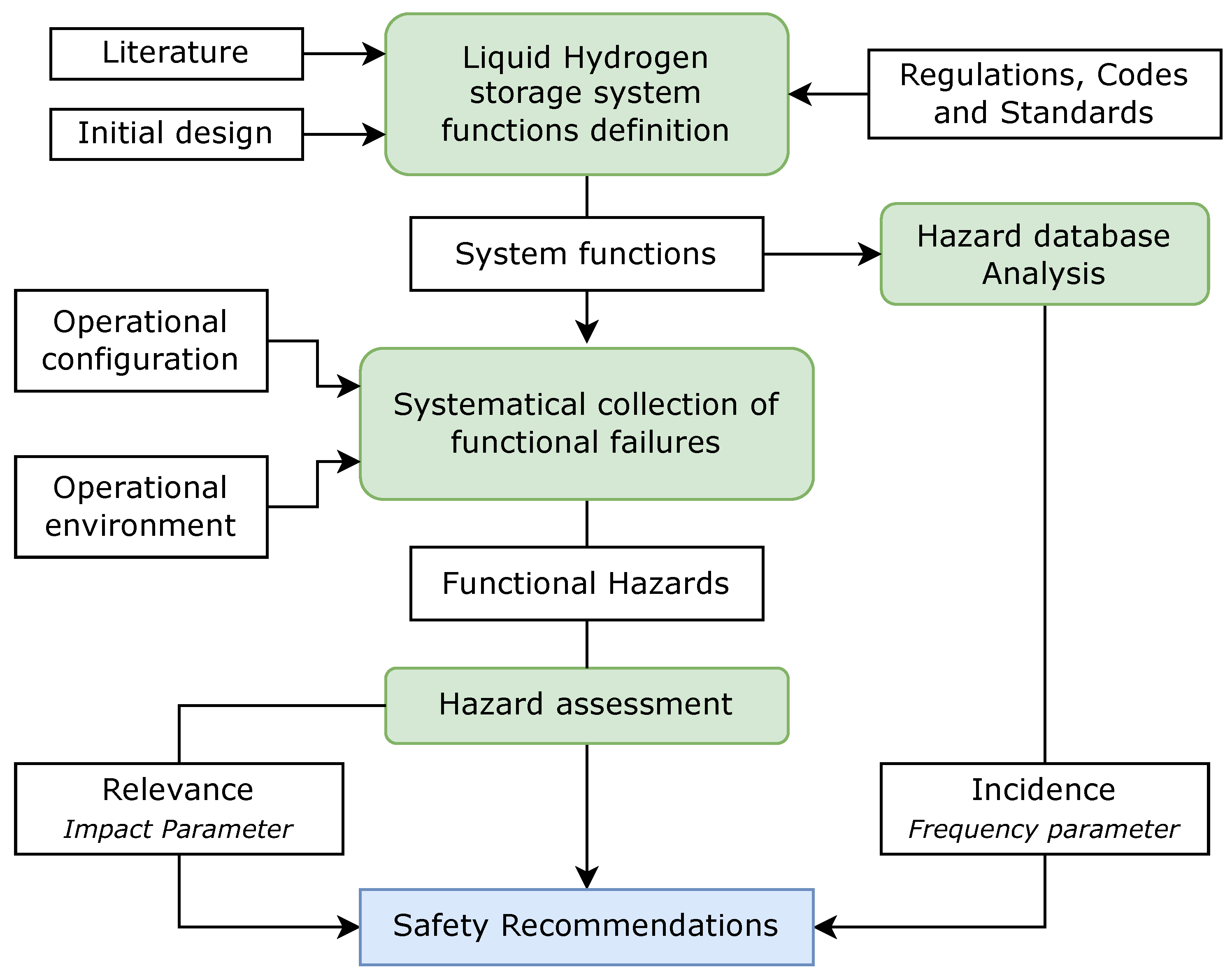
Figure 2.
Schematic representation of the interfaces of the liquid hydrogen fuel storage system.
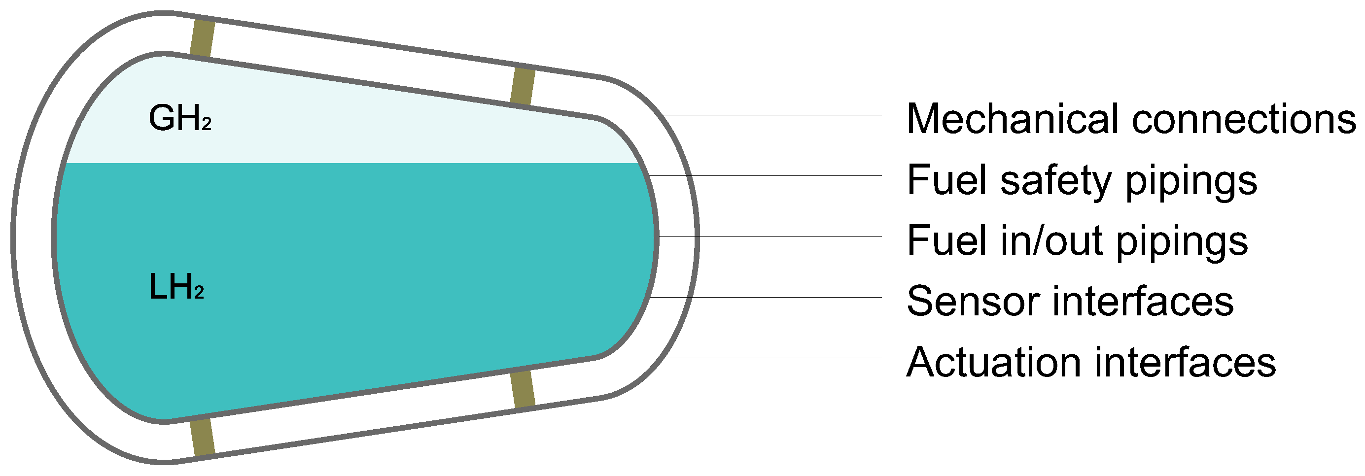
Figure 3.
List of essential functions for a liquid hydrogen tank system used within an aviation vehicle.
Figure 3.
List of essential functions for a liquid hydrogen tank system used within an aviation vehicle.
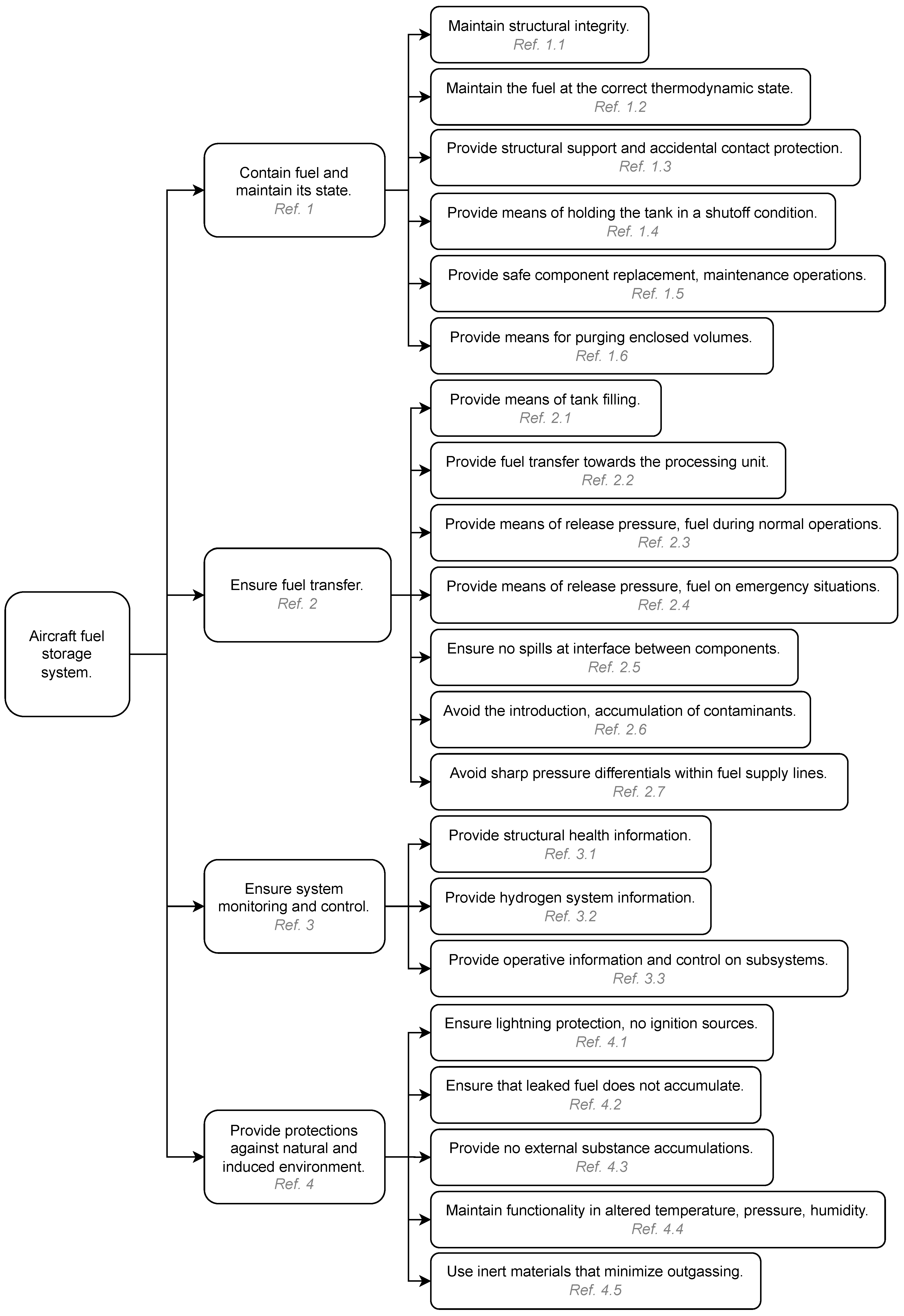
Figure 4.
Distribution of the hazards identified in this study among the five classified categories.
Figure 4.
Distribution of the hazards identified in this study among the five classified categories.
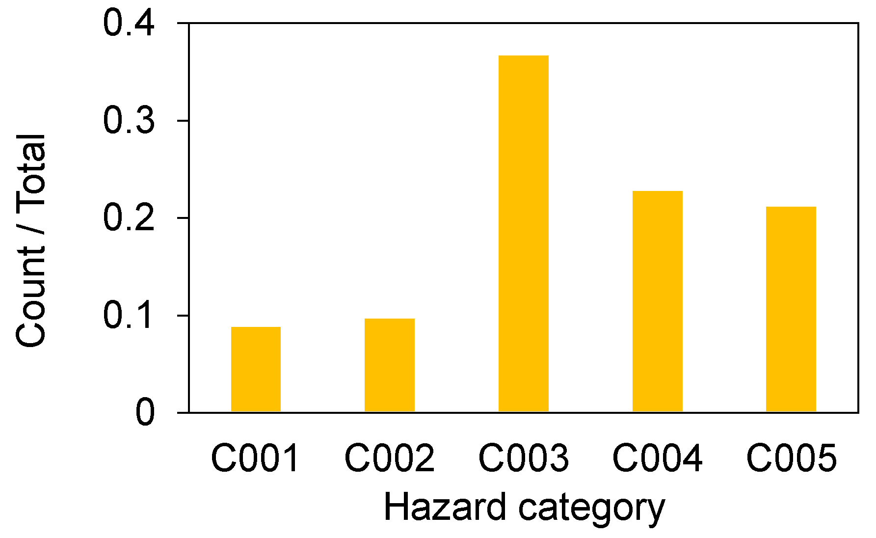
Figure 5.
Counts of the hazard database incidents associated with the liquid hydrogen storage system functions, classified by incident severity.
Figure 5.
Counts of the hazard database incidents associated with the liquid hydrogen storage system functions, classified by incident severity.
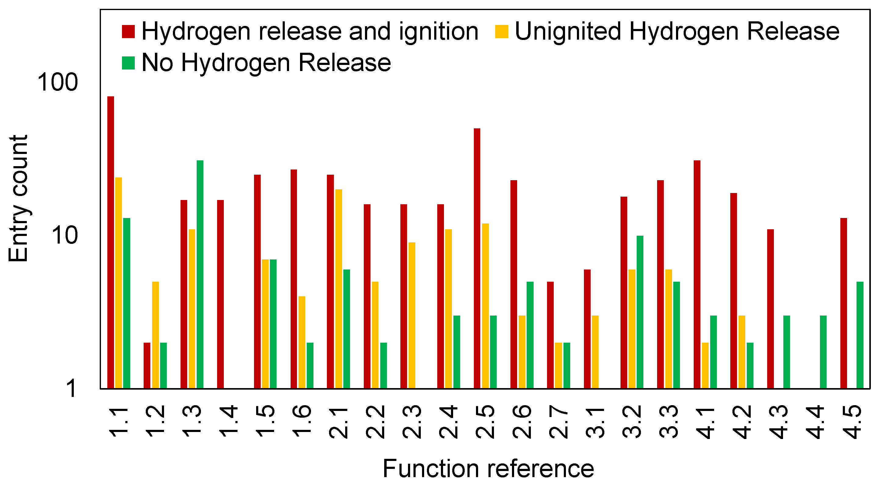

Table 1.
Weights assigned to functional failure severity classes.
| Functional failure severity | WFHA |
|---|---|
| Catastrophic | 2 |
| Hazardous | 1 |
| Major | 0.5 |
| Minor | 0.1 |
| No effect | 0 |
Table 2.
Normalization rules to linearize the FO parameters and further determining the safety recommendations incidence parameter.
Table 2.
Normalization rules to linearize the FO parameters and further determining the safety recommendations incidence parameter.
| Function input | Output |
|---|---|
| < 2 | 1 |
| < 3 | 1.25 |
| < 4 | 1.5 |
| >= 4 | 2 |
Table 3.
Top identified safety recommendations ordered with ascending risk index.
| ID | Description | Risk |
|---|---|---|
| S031 | Prevent fuel leaks through fittings by using pressure locking, failproof strategies, and systematic inspections, while avoiding welded connections, inadequate surface preparation, incorrect usage, vibration. | 3.14 |
| S002 | Prevent collisions and crashes of the storage system during operations by installing sufficient mechanical barriers. | 3.00 |
| S050 | Ensure discharge path for lightnings are provided, and the surface of the vessel and the attached component is ESD compliant as indicated in AIAA G-095. | 3.00 |
| S005 | Ensure the tank wall permeation rate stays below the dormancy threshold under panel cryogenic conditions. Test tank wall samples for permeation under the operative cryogenic conditions. | 2.67 |
| S021 | Implement technologies for hydrogen release as a failsafe for emergencies, ensuring safe fuel dumping is always possible. Provide remote operation. | 2.64 |
| S024 | Designate an unsafe zone around the demonstrator during testing and install ventilation barriers to safeguard operators in the event of a hydrogen release. | 2.50 |
| S047 | Establish a procedure for purging and purge verification of tank and tubing. | 2.50 |
| S003 | Ensure that the frequency of valve failure remains consistently below a defined frequency threshold per flight hour for all applicable fluid flow conditions. | 2.36 |
| S035 | Provide redundancy in PRDs, ensuring they are installed on all isolated lines and connected properly to the vent line. | 2.29 |
| S009 | Design a safe venting system as defined in related standards such as CGA 5.5 to prevent risks such as backfire or detonation. | 2.25 |
| S022 | Prevent overfill by using diverse technologies for hydrogen metering and by pre-calculating the applicable flow from the fuel source. | 2.25 |
| S034 | Verify fuel and its quality (purity, vapor mass fraction, spin state) before filling to prevent accumulation of unwanted substances. | 2.25 |
| S049 | Ensure the control system can enforce operative limits determined following the system specifications. | 2.25 |
| S040 | Ensure that the percentage of tank wall voids due to improper manufacturing process conditions remains below a critical threshold and is not localized. | 2.00 |
| S023 | Implement automated systems to monitor and guide the fuelling process steps, halting openings if detachment or errors such as missing connection of ground venting are detected. | 1.95 |
Disclaimer/Publisher’s Note: The statements, opinions and data contained in all publications are solely those of the individual author(s) and contributor(s) and not of MDPI and/or the editor(s). MDPI and/or the editor(s) disclaim responsibility for any injury to people or property resulting from any ideas, methods, instructions or products referred to in the content. |
© 2025 by the authors. Licensee MDPI, Basel, Switzerland. This article is an open access article distributed under the terms and conditions of the Creative Commons Attribution (CC BY) license (http://creativecommons.org/licenses/by/4.0/).
Copyright: This open access article is published under a Creative Commons CC BY 4.0 license, which permit the free download, distribution, and reuse, provided that the author and preprint are cited in any reuse.


