
Submitted:
22 December 2024
Posted:
23 December 2024
You are already at the latest version
Abstract
To develop crude oil production, we investigated several solvents in produced water treatment. This study inspects the direct influences of some solvents on improving recovery and reuse to the crude oil export streamlines. Produced water is characterized by the presence of trace amounts of petroleum, which form complex emulsions that are difficult to break down. A method to purify produced water involves breaking these emulsions with solvents, thereby inducing the coalescence of oil droplets, and facilitating their complete separation. In this work, 40 different solvents have been evaluated to determine their suitability for purifying produced water. Suitability criteria included efficiency in crude oil recovery, cost-effectiveness, toxicity, and availability. To facilitate comprehensive analysis, these solvents were categorized into families based on their chemical characteristics and potential interaction mechanisms. The families were linear aliphatic hydrocarbons, aliphatic and aromatic cyclic hydrocarbons, chlorinated hydrocarbons, alcohols and glycols, low and high molecular weight ethers, ketones, esters, and a miscellany of solvents with special characteristics. Among all the solvents analysed, xylene and cyclohexane are recommended for the purification of produced water due to their high efficiency in the recovery of residual oil. The Hansen solubility parameters (HSP) reveal that oil emulsions in produced water exhibit three solubility spheres. Solvents with solubility parameters within these spheres are effective destabilisers of the emulsions. Additionally, they are readily available, cost-effective materials suitable for the petroleum industry, and capable of being reused within the process. Tetrahydrofuran is also commendable for its extremely high efficiency, availability, low cost, ease of recycling, and reuse in the process, as well as its low toxicity. In conclusion, applying solvents is an effective and viable alternative for the purification of produced water. This method not only achieves high efficiencies in the recovery of residual oil, which can be commercialised to offset the costs, but also the produced water obtained after the purification process is of excellent quality.
Keywords:
produced water
; purification of produced water
; oil
; petroleum
; complex emulsions
; solvents
; Hansen solubility parameters
; xylene
; cyclohexane
; tetrahydrofuran
1. Introduction
During the extraction of crude oil, an undesirable and highly contaminating byproduct is generated: produced water, which occurs in quantities equal to, or even exceeding double, those of the crude oil. Recognising the critical role of the oil industry in sustaining the global energy supply, this sector has consistently extracted over 4 billion metric tons of oil annually in the past decade [1], equating to nearly 80 million barrels per day. As oil reserves diminish, the necessity for additional water injection to maintain extraction rates becomes more pressing. The oil content in produced water usually spans from 300 ppm to 1,000 ppm, a significant quantity that demands careful consideration.
A substantial portion of this produced water (PW) is recycled for reinjection into wells, yet the remainder requires treatment before being discharged either on land or at sea. However, existing treatment methods have yet to reach the level of efficiency required to satisfy the imminent higher standards for water quality. The conventional process for removing residual oil involves primary separation, which reduces oil content from as high as 1,000 ppm to around 100-200 ppm, followed by secondary treatment that further reduces oil levels to between 10 ppm and 40 ppm. While these levels meet current standards in most oil-producing regions, future trends, spearheaded by Norway's regulations for oil platforms, aim for zero harmful emissions, a goal that current technology cannot yet achieve.
State-of-the-art final cleaning treatments can only reduce oil concentrations to about 15 ppm, falling short of the ultimate target of complete eradication.
1.1. Traditional Industrial Methods for Produced Water Treatment
Primary treatment of produced water like coagulation coalescence, aimed at removing larger oil droplets from PW and sedimentation. Petroleum companies are using main methods that can be conducted using various conventional methods such as those listed below which do not satisfy the optimum separation. That is why there have by many attempts by researchers to do experiments in the laboratories to solve this environmental problem.
The final traditional treatments include:
1.2. Laboratory Methods for Produced Water Treatment
In addition to traditional processes for separating crude oil droplets from produced water, there is a variety of innovative experiments and methods developed in laboratories. These are characterized by potentially promising ideas, but also face significant challenges when considering their application on an industrial scale. Some of these methods, which present both advantages and limitations, are discussed below:
- Walnut shell filters or dual media filters [9]
- Catalytic method [10]
- Additional desalination of high salt concentrations if the water is intended for irrigation [11]
- Hydrophilic and hydrophobic fibers [12]
- Ceramic membranes [13]
- Oxidation [14]
- Microalgae [15]
- Activated carbon [16]
- Methods of flooding the oil well with a thickening polymer [25]
- Use of cationic surfactants with a double fatty chain such as esterquat [30]
- Beds of super hydrophilic Al2O3 particles [33]
- Carbon steel method [34]
- Use of polyaluminum chloride [35]
Both traditional industrial processes and recent laboratory-level attempts at purifying produced water are fraught with significant shortcomings. These include low efficiency, lack of scalability for industrial use, high costs, and the inability to recover and market crude oil to offset purification expenses. Additionally, some methods may resolve one environmental issue only to create another. Therefore, the industry requires a simple, highly efficient, and cost-effective purification method that is scalable for large-scale production. Ideally, this method should not only minimize additional costs in crude oil extraction but also provide an economic benefit by recovering and utilizing the crude oil from the produced water.
1.3. Produced Water Stream in Real Oil Production
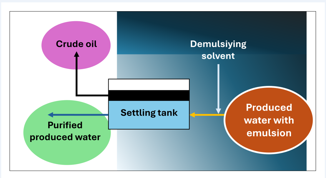
Figure 1 illustrates the flowchart of the general oil extraction and produced water purification procedure. Initially, wet oil is gathered from wells via pipelines converging at point 1, leading to gas isolation stations. The oil undergoes four stages at a pressure of 28 bar, as depicted in the diagram. Upon entry into the separator, it impacts deflector plates, separating gas, water, and oil. Level control is maintained through level and pressure control valves. After the second stage, a dehydrator is installed to extract water, which also contains dissolved salts. This process is conducted with the addition of a demulsifier and the application of a 380-volt electric current through graphite electrodes submerged in the oil above the water level. Subsequently, a desalter is installed to remove residual salts by introducing steam or pure wash water. This setup prevents conduction and disrupts the water-oil bonds, causing the residual droplets of produced water, laden with oil droplets and forming complex emulsions, to settle at the bottom. These emulsions, not effectively broken down in earlier stages, have oil concentrations varying between 300 and 1000 ppm—a substantial amount necessitating treatment, therefore, purification operations commence from point 2, where the produced water, a byproduct requiring treatment due to its environmental impact and the presence of oil droplets, is extracted. Previously discussed were the traditional and laboratory processes and the shortcomings of most of these methods. An integral solution to this problem is proposed, based on the use of demulsifying agents consisting of solvents capable of interacting with oil droplets and breaking the emulsions. For this purpose, a selection of optimal materials is necessary, adhering to established principles and standards. At point 3, following the prior addition of the solvent, oil is separated in settling tanks.
Resolving the treatment of produced water superficially is insufficient, because crude oil production gives the huge amounts of produced water generated daily worldwide. Therefore, establishing a standard solution is challenging, considering the diverse conditions of oil-producing nations and the existence of wells in marine, onshore, and offshore environments. The adopted approach also includes a salt removal process at point 4 using an evaporation method, collecting the salts from the bottom through sedimentation. Condensed pure water, in the form of steam, is collected in a tank at point 5 for uses such as irrigation or general purposes, or it is re-evaporated for use in washing salts in the desalting stage. All these processes utilize the energy from gas combustion to capitalise on energy that would otherwise be wasted.
1.4. Objective
Although numerous industrial techniques are available and innovative proposals at the laboratory level for the purification of produced water exist, the use of solvents has not yet been studied. These solvents should be capable of breaking emulsions to induce the coalescence of oil droplets and thus their separation as a supernatant. The oil thus recovered can be commercialised and, therefore, will pay for the water purification costs. Depending on the solvent used, the recovery may involve a standard additional refining process to recycle the solvent.
The objective of this study is to assess the effectiveness of various solvents for purifying produced water. The evaluation will consider their efficacy in oil recovery, as well as factors such as cost, toxicity, and availability, aiming to identify the most suitable solvent or solvents.
2. Materials and Methods
2.1. Preparation of Produced Water and Purification Procedure
Laboratory-prepared produced water under conditions simulating real-world scenarios is used. The procedure involves adding sodium chloride to water until reaching a concentration of 80,000 ppm. Under magnetic stirring and in a water bath at 45°C, 150 ppm of crude oil is added until it emulsifies. The oil comes from oil wells in Iraq. Exactly 100 cm3 of the prepared produced water is placed into a beaker. Volumes of solvents of 5, 10, 15, 20, and 25 cm3, respectively, are added for each of the five experiments conducted with each solvent. The contents of the beaker are stirred to ensure thorough mixing and the coalescence of emulsion droplets. Subsequently, it is allowed to stand for 10 minutes to allow the oil with solvents less dense than water to float to the surface. In this case, 10 cm3 of the purified produced water is extracted from the bottom of the beaker. Conversely, when the solvents are denser than water, they settle at the bottom, and the extraction of the purified produced water is done halfway up.
2.2. Determination of Residual Oil Concentration in Treated Produced Water
5 cm3 of tetrachloroethylene (Labkem, Tetrachloroethylene GLR >99.9%, CAS 204-825-9) are added to 5 cm3 of previously purified produced water. Tetrachloroethylene is used as it is superior to other solvents as a reference for measuring the amount of oil in water [37]. Afterwards, the oil concentration was measured using a UV spectrophotometer (Cary 100 BIO from Varian), based on a standard curve previously prepared at 311 nm:
Cp = 105.39 A
This curve was established beforehand using concentrations of produced water ranging from 5 to 120 ppm. The fit is excellent since R²=0.9999.
2.3. Solvents
Data on the solvents used are shown in Table 1.
2.2. Software
To determine the Hansen solubility parameters of the emulsions in produced water, the Techné Solubility 3S software, developed by the Techné research group at the University of Granada, was employed. This software is characterised by its ability to determine the solubility parameters of the centres of up to three solubility spheres, as well as their radii.
3. Results
In Table 2, the concentrations of residual oil, Cp, after the treatment of produced water using the methodology previously described, are presented. Additionally, the percentages of oil recovery, denoted as R, determined according to the expression, are also presented:
4. Discussion
4.1. Hydrocarbons and Chlorinated Hydrocarbons
4.1.1. Linear Aliphatic Hydrocarbons
Figure 2a illustrates the relationship between the volume of solvent per 100 ml of produced water and the percentage of residual oil removed, focusing on various aliphatic hydrocarbons. For hydrocarbons with low molecular weight (such as n-heptane, isooctane, and petroleum ether), oil recovery effectiveness remains moderate, peaking at 52%. Interestingly, a proportional increase in solvent volume correlates with enhanced oil recovery rates. However, substances like vaseline (liquid) and liquid paraffin show no efficacy in this process. Notably, escalating vaseline and paraffin volumes can inversely impact oil recovery, leading to a complete lack of recovery at 25 ml.
Figure 2b reveals that hydrocarbons with 7 to 8 carbon atoms exhibit the best recovery, whereas effectiveness notably declines for those with higher molecular weights. This is explained by the ability of smaller molecules to destabilize the oil-water emulsion interface, facilitating oil droplet coalescence. On the contrary, vaseline and liquid paraffin, being macromolecules, contribute to the stabilization of these emulsions. The increased viscosity of these substances further amplifies this effect, known to enhance the stability of emulsions
4.1.2. Cyclic Hydrocarbons
Cyclic hydrocarbons, encompassing both aliphatic and aromatic types, significantly outperform linear aliphatic hydrocarbons in oil recovery efficiency, as shown in Figure 2c. These cyclic molecules likely experience fewer steric hindrances compared to their linear counterparts, enhancing their ability to destabilize the oil-water interface. Consider limonene, which possesses a branched substituent within its cycle. Though not excessively large, this structure might introduce some steric hindrance, potentially limiting its effectiveness in destabilizing emulsions. Xylene, with its two methyl substituents positioned ortho, meta, or para, is small enough to facilitate droplet coalescence, seemingly acting as 'destabilizing tweezers'. Both xylene and cyclohexane demonstrate high efficacy, even in low volumes. Additionally, these substances are not only readily available and cost-effective but also recyclable and reusable in water purification processes, provided the right recovery system is in place. In terms of toxicity and handling, within the context of the oil extraction industry, they are not deemed hazardous, offering a practical advantage in this sector.
4.1.3. Chlorinated Hydrocarbons
Incorporating chlorine atoms into hydrocarbons markedly enhances oil recovery in water purification processes. As depicted in Figure 2d, recovery rates soar to between 90% and 100%, with carbon tetrachloride being particularly notable. Dichloromethane and chloroform also show exceptional effectiveness in these processes. The high electronegativity of chlorine atoms potentially alters the emulsion's zeta potential, leading to efficient droplet coalescence and complete oil separation. Despite their efficacy, the industrial application of these chlorinated hydrocarbons is advised against due to associated risks. Tetrachloroethylene, for instance, decomposes into corrosive and toxic substances like hydrochloric acid and trichloroacetic acid in moist environments. Its violent reaction with aluminium, coupled with environmental hazards, particularly to aquatic systems, renders it a less favourable choice. Dichloromethane, which has a boiling point of 40°C, is unsuitable for high-temperature applications without additional cooling, as the temperature of produced water often exceeds 45°C. Chloroform, although less technologically challenging due to its higher boiling point of 61°C, poses health risks including central nervous system effects and potential carcinogenicity.
4.2. Alcohols
4.2.1. Monohydric Alcohols
Monohydric alcohols with 1 to 4 carbon atoms are notably effective in recovering oil from produced water. In contrast, 2-phenylethanol exhibits moderate efficiency. The size of its aromatic ring appears to create steric hindrance, reducing its effectiveness compared to its counterparts with 1 to 4 carbon atoms (Figure 3a). It has also been observed that the position of the hydroxyl group within the carbon chain does not impact the efficiency of oil recovery: both 1-propanol and 2-propanol demonstrate identical effectiveness. Figure 3b illustrates oil recovery percentages as a function of the carbon atom count, revealing that the efficacy of monohydric alcohols is inversely proportional to the number of carbon atoms [37].
4.2.2. Polyhydric Alcohols
Glycols, possessing 2 OH groups and with 2, 3, or 6 carbon atoms, are slightly less effective than monohydric alcohols in oil recovery, as demonstrated in Figure 3c. However, as with glycerin, the introduction of a third OH group leads to a stronger affinity for the aqueous phase over the oily phase. Despite high concentrations of salts in the water, particularly sodium chloride, glycerin dissolves well and becomes solvated. This solvated glycerin can encapsulate oil droplets, thereby increasing their zeta potential. Consequently, this results in electrostatic repulsion that prevents droplet aggregation and coalescence, potentially even stabilizing the emulsion. Indeed, the addition of just 5 ml of glycerin to 100 ml of produced water achieves a mere 2.2% oil recovery. When 25 ml is added, the recovery is virtually non-existent, at only 0.1%.
To assess the influence of the number of hydroxyl groups for a constant carbon number, 4 different C3 alcohols were compared: 1-propanol, 2-propanol (1 OH), propylene glycol (2 OH), and glycerin (3 OH). As expected, and in line with the previous paragraph, alcohols with a single OH group are the most effective (regardless of whether the OH is in the 1 or 2 position), followed by propylene glycol (with 2 OH), and almost complete inefficacy for glycerin with 3 OH (Figure 3d and 3e)
Except for glycerin, the effectiveness of alcohols is high, though it doesn't reach the desired standards of near-complete purification of produced water. However, in their favor are highly advantageous factors such as widespread industrial availability, very low cost, and easy recyclability. Ethylene glycol and methanol are exceptions, as they are toxic to higher life forms. Nonetheless, the other alcohols analysed are minimally toxic to humans and the environment. If near-complete purification is not required, they could be a good alternative for industrial applications.
4.3. Ketones
Three ketones have been tested: cyclohexanone, acetone, and butanone, yielding varied results (Figure 4a,b). Cyclohexanone is the most effective, achieving high oil recovery percentages, while the performance of acetone and butanone is mediocre. Focusing on acetone (C3) and butanone (C4), it seems that increasing the number of carbon atoms leads to decreased recovery efficiency, but cyclohexanone, which is a C6, is much more effective. The reason must be the positive effect of the ring structure on oil recovery, as is the case with cyclic hydrocarbons (Figure 2c). Although cyclohexanone does not have as high efficiency as some other solvents, it could be useful in the industry as it has several additional advantages. It is readily available, low in cost, can be easily recycled within the industrial process, and has low toxicity.
4.4. Ethers
Three ethers have been tested: one of low molecular weight, diethyl ether, CH3-CH2-O-CH2-CH3, and two of high molecular weight, polyethylene glycol 400 (PEG 400), HO-(CH2-CH2-O)n-H, and polypropylene glycol 2000 (PPG 2000), HO-(CH2-CH(CH3)-O)n-H. The efficacy in oil recovery is medium to high, with diethyl ether performing slightly better (up to 90%), due to its small molecule size (Figure 5).
Surprisingly, the other two ethers, which are polymers, show acceptable performance, even though polymers usually tend to stabilize emulsions. Diethyl ether has a boiling point of 34,6°C, making it unsuitable for industrial use, as the produced water typically exceeds 45°C and the environment in oil fields can have high temperatures. If other alternatives do not require cooling of the produced water and special storage conditions, it is better not to consider it as a candidate. Moreover, it is toxic due to its narcotic effects and dangerous because it can form explosive mixtures. PEG 400 and PPG 2000, on the other hand, are completely harmless and not dangerous. However, their performance is not sufficient to recommend them for industrial use.
4.5. Esters
In Figure 6, the graphical representation of the percentage of residual oil removed from produced water for various esters and additionally for acetic acid is shown. Surprisingly, decyl oleate, a molecule significantly larger than the others, is the most effective. However, in no case is the efficacy sufficient to recommend its use in the purification of produced water. Also noteworthy is the stabilizing effect of butyl acrylate as its dosage increases. This behaviour may be due to its molecule having a certain surfactant capacity.
The acrylate group, which includes a carboxyl and a conjugated double bond, acts as the hydrophilic group of the surfactant, and the butyl acts as the lipophilic group (Figure 7).
Esters, although they are readily available, low-cost, and non-hazardous materials, have the disadvantage of their low efficiency in oil removal, and therefore are not recommended for industrial use.
4.6. Miscellanea
To conclude, Figure 8 depicts a variety of solvents that cannot be classified into the chemical families previously analysed. Undoubtedly, the most notable is the exceptionally high performance of tetrahydrofuran, with virtually 100% recovery at all dosages. It is a small, cyclic molecule with an appropriate degree of ionization, thereby combining various advantages of xylene, cyclohexane, and chlorinated hydrocarbons. In this respect, it is the most advantageous solvent of all. It has low viscosity and low density, which favours the flotation of the recovered oil. Additionally, with a boiling point of 66 °C, it can be easily distilled and reused in the process. It is not especially toxic, but it has the drawback of potentially forming explosive epoxides when distilled to dryness. This situation must be avoided.
Regarding N,N-dimethylformamide, diethanolamine, and acetonitrile, molecules with different nitrogenous groups, do not exhibit sufficient oil recovery capacity to be recommended for use. The behaviour of dimethyl sulfoxide is striking, a very small and polarized molecule that stabilizes the oil emulsion as its dosage increases. This behaviour can be likened to that of glycerin, as previously discussed, as it can be interpreted as the effect of dimethyl sulfoxide's affinity for water, its solvation, and probably its ability to increase the zeta potential of the oil droplets in the emulsion.
4.7. Hansen Solubility Parameters and Produced Water
A basic rule of chemistry is that ‘like dissolves like’. However, it is intriguing that substances with markedly different functional groups, such as xylene, cyclohexanone, methanol, or tetrahydrofuran, are capable of effectively dissolving the residual oil in produced water. Conversely, substances with the same functional group, such as cyclohexanone, acetone, and butanone—all ketones—exhibit markedly different capacities for dissolving the residual oil in produced water.
An approach that can explain these seemingly inexplicable behaviours is the Hansen Solubility Parameters (HSP) [38]. According to Hansen, two substances interact with each other and dissolve in one another if their cohesion energies are similar. It is proposed that the cohesion energy of a substance comprises three components: energy due to London dispersion forces, ED, energy due to polarity of molecules, EP, and energy due to hydrogen bonding, EH:
If the total solubility parameter is defined as the square root of the cohesion energy density as:
The parameters of dispersion, polarity, and hydrogen bonding respectively as:
Therefore:
In the three-dimensional Hansen space, the distance between two substances, 1 and 2, is defined as:
This definition is like the definition of distance in Euclidean spaces, with the exception that the term related to the dispersion solubility parameters, dD1 and dD2, is multiplied by 4. The Hansen solubility parameters of any substance form the centre of a ‘solubility sphere’, with a radius Ro, where ‘good solvents’ for the considered substance have a distance to the centre, Ra, equal to or less than the solubility radius, and ‘poor solvents’ have a greater distance. The parameter Radius of Energy Difference, RED, is defined as:
Therefore, RED ≤ 1 for good solvents of the considered substance and RED > 1 for poor solvents. These conditions can be extended to any energetic interaction between substances, not only for solubilisation processes but also for adsorption, absorption, coating resistance, suspension stability, free surface energy [39] or for the specific case addressed in this article: the destabilization of oil emulsions in produced water by solvents.
From the perspective of Hansen solubility parameters, the present study considers the criterion that a solvent is an “effective destabilizer” of oil emulsions when, upon treating 100 ml of produced water with 25 ml of the solvent, the residual oil concentration, R, is reduced to less than 20 ppm. Table 3 presents the Hansen solubility parameters of the tested solvents. Solvents that are effective destabilisers have been marked with a "1", while ineffective ones are marked with a "0". If the solvent is “effective destabiliser”, a "1" is assigned, and otherwise, a "0".
After entering this information into the Techné Solubility 3S software, it was found that the produced water exceptionally exhibits three solubility spheres (Figure 9). This explains why solvents with very different cohesion energies are capable of effectively destabilising oil emulsions in produced water and purifying it. The most lipophilic solvents are grouped within the sphere with the lowest hydrogen bonding solubility parameter (sphere L). In contrast, the most hydrophilic solvents, with the highest hydrogen bonding parameter, are in sphere H, while those with an intermediate hydrogen bonding parameter are found in sphere LH. The figure presents two- and three-dimensional representations of the spheres, while the Table 4 displays the solubility parameters of the centers of spheres and their radii.
4.8. Stability of Oil Emulsions in Produced Water
The high stability of oil emulsions in produced water is due to the emulsifying capacity of the asphaltenes and resins that, together with hydrocarbons, make up crude oil. An example of an asphaltene molecule and an example of a resin molecule are shown in Figure 10 [40].
Asphaltenes are very complex molecules, with a molecular weight greater than 1000 g/mol made up of a nucleus of aromatic rings, aliphatic side chains and heteroatoms such as O, S and N, that act as polar functional groups. Resins are molecules like asphaltenes but with a molecular weight of less than 1000 g/mol. These complex molecules combine lipophilic structures together with hydrophilic structures that give them amphiphilic character and therefore show surfactant behaviours. Figure 11 shows a graphical representation of a multiple emulsion of oil in produced water and a detail of the location of molecules and ions at the oil-produced water interface.
Asphaltene molecules, due to their flat structure, form overlapping layers in which their polar groups face each other. These layers, near the interface, also orient their hydrophilic polar groups towards the aqueous phase. Resins intercalate their lipophilic chains between the alkyl chains of the asphaltenes and position their polar groups towards the aqueous phase. They also align their polar groups with the polar groups of the asphaltenes through a solvation process. The result is a highly stable structure.
Therefore, to purify the produced water, it is necessary to induce the coalescence of the oil droplets, which can be achieved by destabilising these structures. One strategy is to add a solvent that, due to its molecular structure, can intercalate between the intermolecular bonds between asphaltenes and resins. Since asphaltenes and resins are bonded by both non-polar and polar groups, both non-polar and polar solvents can be used for this purpose.
This also justifies why the emulsions in produced water exhibit three solubility spheres, as demonstrated earlier.
5. Conclusions
This work has demonstrated that:
- Among all the solvents analysed, xylene and cyclohexane are recommended for the purification of produced water due to their high efficiency in the recovery of residual oil.
- The Hansen solubility parameters (HSP) reveal that oil emulsions in produced water exhibit three solubility spheres. Solvents with solubility parameters within these spheres are effective destabilisers of the emulsions.
- Additionally, they are readily available, cost-effective materials suitable for the petroleum industry, and capable of being reused within the process.
- Tetrahydrofuran is also commendable for its extremely high efficiency, availability, low cost, ease of recycling, and reuse in the process, as well as its low toxicity.
In conclusion, applying solvents is an effective and viable alternative for the purification of produced water. This method not only achieves high efficiencies in the recovery of residual oil, which can be commercialised to offset the costs, but also the produced water obtained after the purification process is of excellent quality.
6. Patents
Part of the results of this manuscript are described in the Spanish patent application number P202431030, filed on 10 December 2024.
Author Contributions
Conceptualization, Aqeel Shaikhah Arafat Aljadiri and Rafael Bailón-Moreno; Formal analysis, Aqeel Shaikhah Arafat Aljadiri and Rafael Bailón-Moreno; Investigation, Aqeel Shaikhah Arafat Aljadiri and Rafael Bailón-Moreno; Methodology, Aqeel Shaikhah Arafat Aljadiri and Rafael Bailón-Moreno; Software, Rafael Bailón-Moreno; Writing – original draft, Aqeel Shaikhah Arafat Aljadiri and Rafael Bailón-Moreno; Writing – review & editing, Aqeel Shaikhah Arafat Aljadiri.
Funding
This research received no external funding.
Institutional Review Board Statement
Not applicable.
Informed Consent Statement
Not applicable.
Data Availability Statement
The original contributions presented in this study are included in the article. Further inquiries can be directed to the corresponding author(s).
Acknowledgments
This work has been carried out as part of the research of the doctoral thesis of Aqeel Shaikhah Arafat Aljadiri, directed by Rafael Bailón-Moreno. The doctoral thesis belongs to the Doctoral Program in Chemistry of the University of Granada (codes ISCED 1 Chemistry and ISCED 2 Physical, Chemical, Geological Sciences). Escuela Internacional de Postgrado of Universidad de Granada.).
Conflicts of Interest
The authors declare no conflicts of interest.
References
- Petróleo: producción mundial 1990-2022. Estatista. Available online: https://es.statista.com/estadisticas/635470/volumen-de-petroleo-producido-a-nivel-mundial/ (Accessed on 12/03/2024).
- Mastouri, R. et al. (2010) 2010: A time to review the produced water treatment technologies. A time to look forward for new. 17th Annual Petroleum and Biofuels Environmental Conference [IPEC], San Antonio, TX, USA. https://www.avividwater.com/uploads/1/3/1/6/131696832/mastouri_2010_a_time_to_review_the_produced_water_treatment_technologies.pdf (Accessed on 12/03/2024).
- Pangestu, N.L. et al. Produced Water Treatment Planning Using Corrugated Plate. Serambi Engineering 2021, 6 (4), 2286 - 2293.
- Majid I. Abdul-Wahab et al. Oil Removal from Wastewater of Al -Al-Bezerqan Crude Oil Field by Air Flotation. Iraqi Journal of Chemical and Petroelum 2004, 5, 41-47.
- Alley, E.R. Water Quality Control Handbook Associates, 2ª ed.; The McGraw-Hill Companies, Inc: New York, 2007.
- Hayes, T. et al. Overview of Emerging Produced Water Treatment Technologies. In proceeding of the 11º Annual International Petroleum Environmental Conference. Albuquerque, USA, 2004.
- Sheng, J.J. Modern Chemical Enhanced Oil Recovery Theory and Practice. Elsevier ed., 2010.
- Salahia, A. Oily wastewater treatment using ultrafiltration. Desalination and Water Treatment 2009, 6, 1-3, 289-298. DOI: 10.5004/dwt.2009.480.
- Dey, A.K. What is Produced Water? | Produced Water Treatment Processes. Available online: https://whatispiping.com/produced-water-treatment/ (Accessed on 12/03/2024).
- Felch, C.L. et al. Catalytic systems and methods for process stream treatment. Patent WO2015161187A2, 2015.
- Stewart, D.R. et al. Purification of oil field production water for beneficial use. Patent US8097163B1, 2007.
- Chase, G. et al. Mixed hydrophilic/hydrophobic fiber media for liquid-liquid coalescence. Patent US20100200512A1, 2010.
- Zhong, J. et al. Treatment of oily wastewater produced from refinery processes using flocculation and ceramic membrane filtration. Separation and Purification Technology 2003, 32 (1–3), 93-98. https://doi.org/10.1016/S1383-5866(03)00067-4.
- Hassan, A.A. et al. Chemical oxidation for oil separation from oilfield produced water under UV irradiation using Titanium dioxide as a nano-photocatalyst by batch and continuous techniques. International Journal of Chemical Engineering 2019, 1-8. DOI: 10.1155/2019/9810728.
- Nadersha, S. Biological treatment of produced water using algae: A proof of concept. Master Tesis - United Arab Emirates University, 2021.
- Islam, S. Investigation of Oil Adsorption Capacity of Granular Organoclay Media and the Kinetics of Oil Removal from Oil-in-Water Emulsions. Tesis - Texas A&M University, 2006.
- Gao, H. et al. A two-step hydrophobic fabrication of melamine sponge for oil absorption and oil/water separation. Surface & Coatings Technology 2018, 339, 147-154. https://doi.org/10.1016/j.surfcoat.2018.02.022.
- Zhou, J. et al. Reversible wettability switching of melamine sponges for oil/ water separation. Materials Chemistry and Physics 2021, 257, 123772. https://doi.org/10.1016/j.matchemphys.2020.123772.
- Zhang, R. et al. Robust, fluorine-free and superhydrophobic composite melamine sponge modified with dual silanized SiO2 microspheres for oil–water separation. Chinese Journal of Chemical Engineering 2020, 23, 50-60. https://doi.org/10.1016/j.cjche.2020.06.006.
- Zhanga, L. et al. Cost-effective one-pot surface modified method to engineer a green superhydrophobic sponge for efficient oil/water mixtures as well as emulsions separation. Colloids and Surfaces A: Physicochemical and Engineering Aspects 2019, 576, 43-54. https://doi.org/10.1016/j.colsurfa.2019.05.022.
- Xie, A. et al. Facile and green fabrication of superhydrophobic sponge for continuous oil/ water separation from harsh environments. Colloids and Surfaces A: Physicochemical and Engineering Aspects 2019, 563, 120-129. https://doi.org/10.1016/j.colsurfa.2018.12.009.
- Lei, Z. et al. Ultralight, robustly compressible and super-hydrophobic biomass-decorated carbonaceous melamine sponge for oil/water separation with high oil retention. Applied Surface Science 2019, 489, 922-929. https://doi.org/10.1016/j.apsusc.2019.06.025.
- Nguyen-Dinh, M.T. et al. Superhydrophobic MS@CuO@SA sponge for oil/water separation with excellent durability and reusability. Chemosphere 2022, 292, 133328. https://doi.org/10.1016/j.chemosphere.2021.133328.
- Shayesteh, H. et al. Durable superhydrophobic/ superoleophilic melamine foam based on biomass-derived porous carbon and multi-walled carbon nanotube for oil/water separation. Nature. Scientific Reports 2023, 13, 4515. https://doi.org/10.1038/s41598-023-31770-x.
- Dano, J. et al. Simulation Study on Polymer Flooding for Enhanced Oil Recovery: A Case Study. Materials Today: Proceedings 2019, 19, 1507–1513. https://doi.org/10.1016/j.matpr.2019.11.175.
- Bhushan, B. Bioinspired oil–water separation approaches for oil spill clean-up and water purification. Philsophical Transactions A 2019, 377, 20190120. http://dx.doi.org/10.1098/rsta.2019.0120.
- Sun, Y. et al. Fabrication of Carbon Aerogels Derived from Metal-Organic Frameworks / Carbon Nanotubes / Cotton Composites as an Efficient Sorbent for Sustainable Oil–Water Separation. Applied.Sciences 2022, 12, 7285. https://doi.org/10.3390/app12147285.
- Noaman, S. et al. Carbon-based polymer nanocomposite membranes for oily wastewater treatment. Clean Water 2019, 2, 20. https://doi.org/10.1038/s41545-019-0044-z.
- Elhenawy, S. et al. Recent Developments and Advancements in Graphene-Based Technologies for Oil Spill Cleanup and Oil–Water Separation Processes. Nanomaterials 2022, 12, 87. https://doi.org/10.3390/nano12010087.
- Puasa S.W, et al. Enhanced Oily Sludge Dewatering using Plant-Based Surfactant Technology. Materials Today: Proceedings 2019, 19, 1159–1165. https://doi.org/10.1016/j.matpr.2019.11.009.
- Hussein, S.N.C.M. et al. Study of Acid Treated Mixed Sawdust as Natural Oil Sorbent for Oil Spill Materials Today: Proceedings 2019, 19, 1382–1389.
- Aljadiri, A.S.A. Oily Water Treatments for Southern Iraqi Oil Fields. ) Master Thesis - College of Engineering of Nahrain University, Iraq, 2014.
- Kong, W. et al. Superhydrophilic Al2O3 Particle Layer for Efficient Separation of Oil-in-Water (O/W) and Water-in-Oil (W/O) Emulsions. Langmuir, 36, 13285-13291. https://doi.org/10.1021/acs.langmuir.0c02284.
- Rabbani, Y. et al. The effect of superhydrophobicity of prickly shape carbonyl iron particles on the oil-water adsorption. Ceramics International 2021, 47, 28400-28410. https://doi.org/10.1016/j.ceramint.2021.06.257.
- Xu, L. et al. Salinity and Temperature Effects on Oily Produced Water Treatment Using Polyaluminium Chloride. In Proceeding of the Congress Middle East Oil, Gas and Geosciences Show, Manama, Bahrain, February 2023. https://doi.org/10.2118/213688-MS.
- American Chemical Society. CAS SCIFinder. Available online: https://www.cas.org/solutions/cas-scifinder-discovery-platform/cas-scifinder-n (accessed on 15/12/2024).
- Nollet, L.M.L. and Thiele, B. Handbook of Water Analysis, Taylor & Francis Group, LLC, 2007.
- Charles M. Hansen. Hansen Solubility Parameters. A User's Handbook. 2007. Boca Ratón, CRC Press. Taylor & Francis Group.
- Bailón-Moreno, R.; Bailón-Ruiz, M.A.; Aljadiri, A.S.A. Free Surface Energy and Hansen Solubility Parameter Vector Field. Interface Thickness. Applied Sciences 2024, 14, 5834. https://doi.org/10.3390/app14135834.
- Joonai, E. et al. Water versus Asphaltenes; Liquid–Liquid and Solid–Liquid Molecular Interactions Unravel the Mechanisms behind an Improved Oil Recovery Methodology. Scientific Reports 2019, 9, 11369. https://doi.org/10.1038/s41598-019-47782-5.
Figure 1.
Example of a flow chart for crude oil production and produced water treatment.
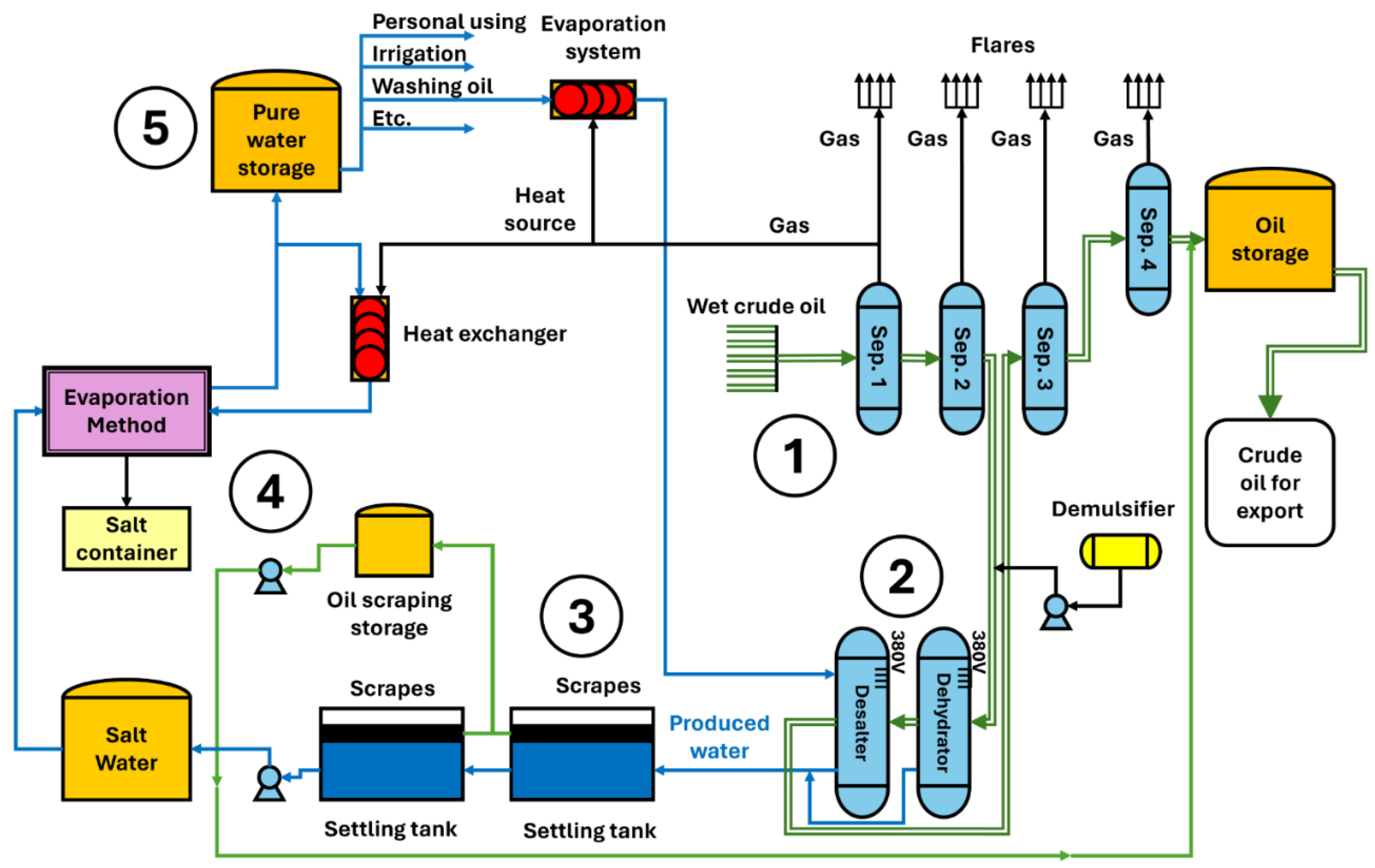
Figure 2.
Percentage of residual oil removed from produced water: a) Aliphatic hydrocarbons, b) influence of the number of carbons in aliphatic hydrocarbons, c) cyclic hydrocarbons, and d) chlorinated hydrocarbons.
Figure 2.
Percentage of residual oil removed from produced water: a) Aliphatic hydrocarbons, b) influence of the number of carbons in aliphatic hydrocarbons, c) cyclic hydrocarbons, and d) chlorinated hydrocarbons.
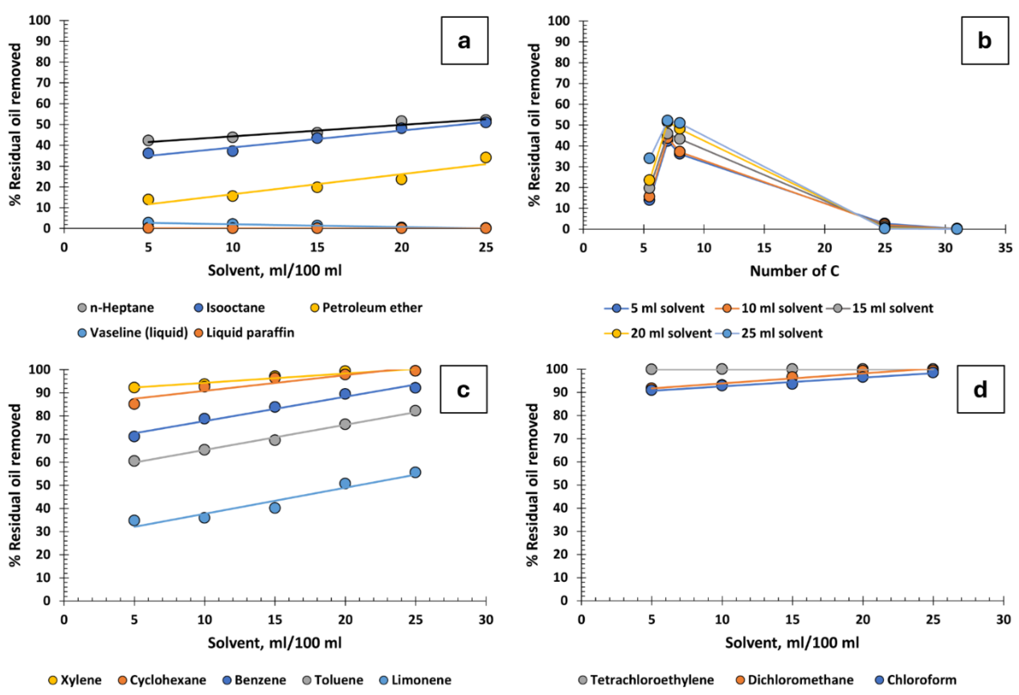
Figure 3.
Percentage of residual oil removed from produced water: a) Monohydric alcohols, b) influence of carbon atom count in monohydric alcohols, c) polyhydric alcohols, d) C3 alcohols, e) influence of the number of hydroxyl groups.
Figure 3.
Percentage of residual oil removed from produced water: a) Monohydric alcohols, b) influence of carbon atom count in monohydric alcohols, c) polyhydric alcohols, d) C3 alcohols, e) influence of the number of hydroxyl groups.
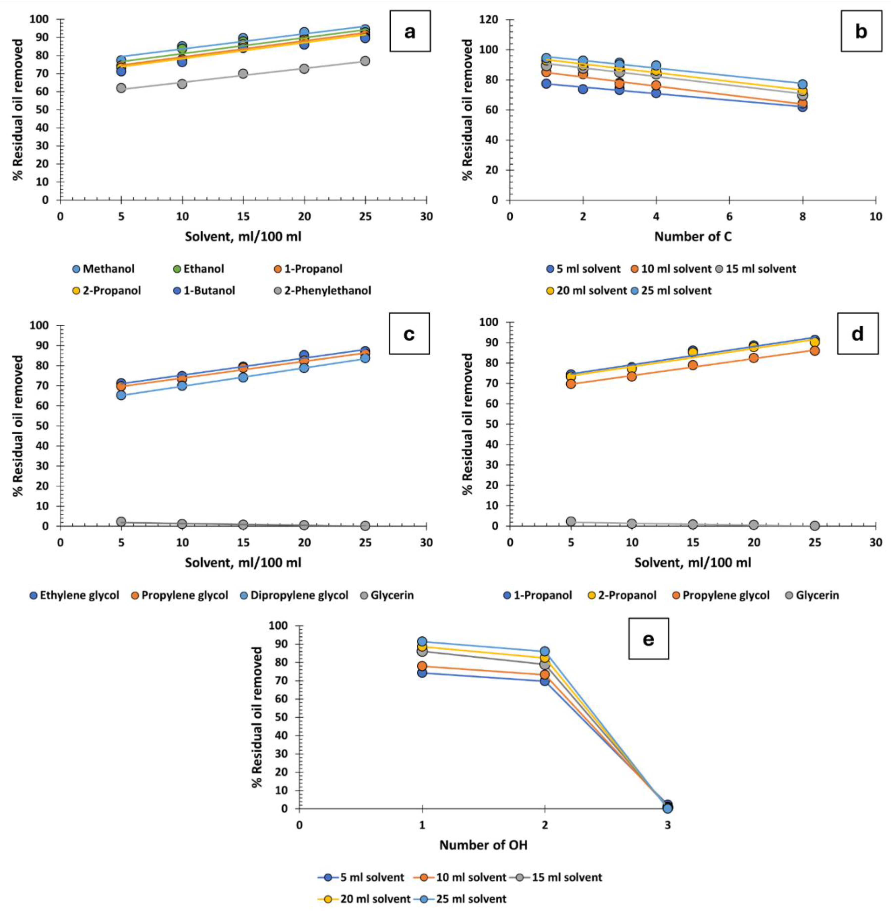
Figure 4.
Percentage of residual oil removed from produced water: a) ketones and b) influence of the number of carbons in ketones.
Figure 4.
Percentage of residual oil removed from produced water: a) ketones and b) influence of the number of carbons in ketones.
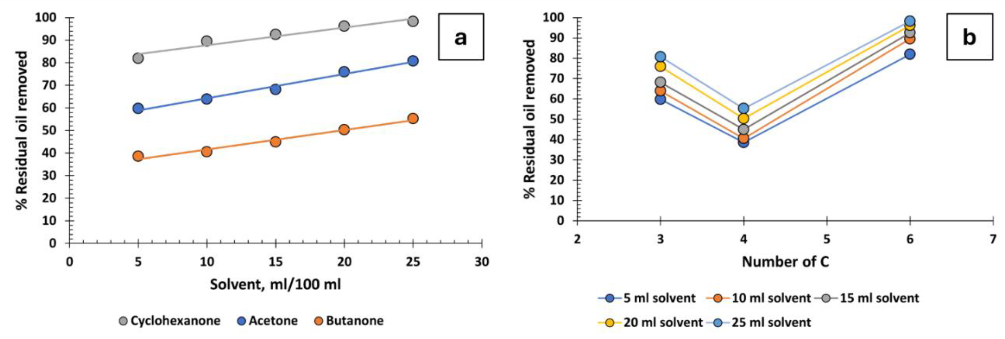
Figure 5.
Percentage of residual oil removed from produced water versus various volumes of ethers.
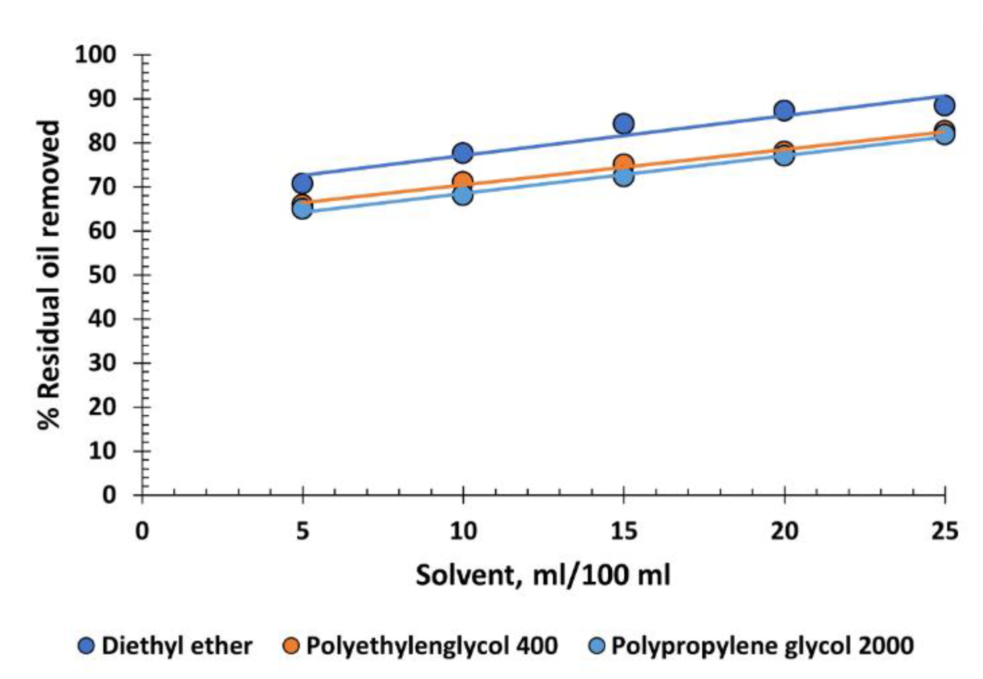
Figure 6.
Percentage of residual oil removed from produced water versus various volumes of esters.

Figure 7.
Butyl acrylate.
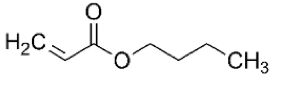
Figure 8.
Percentage of residual oil removed from produced water versus various volumes of solvents.
Figure 8.
Percentage of residual oil removed from produced water versus various volumes of solvents.
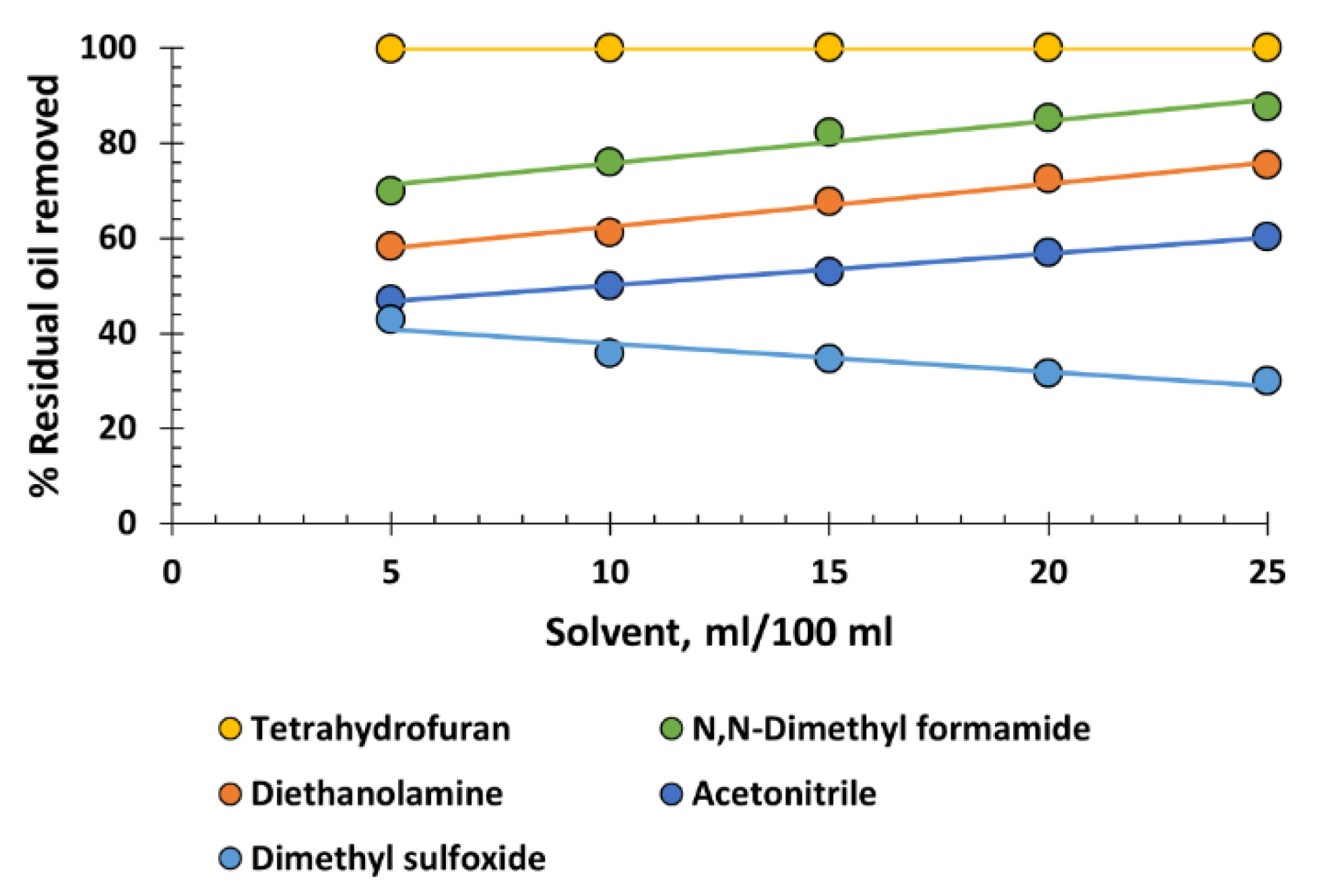
Figure 9.
Graphical representation of the solubility spheres of produced water. On the axes, according to the nomenclature provided by the Techné Solubility 3S software, D, P, and H represent δD, δP, and δH, respectively. The red points represent solvents that are effective destabilisers, while the white points represent those that are not. In the 2D representations, there are white points that may appear to be inside the spheres; however, except for a few exceptions, they are actually located in front of or behind the spheres.
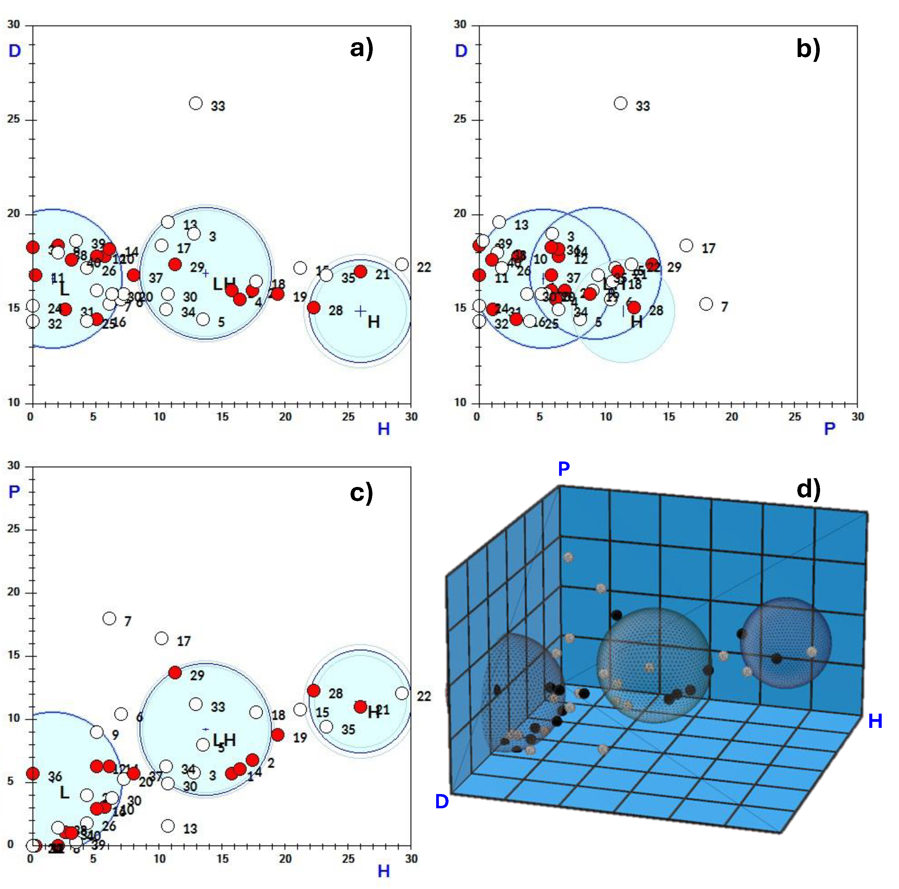
Figure 10.
Example of a) asphaltene and b) resin.

Figure 11.
Multiple emulsion of oil in produced water and detail of the position of molecules and ions at the oil-produced water interface.
Figure 11.
Multiple emulsion of oil in produced water and detail of the position of molecules and ions at the oil-produced water interface.
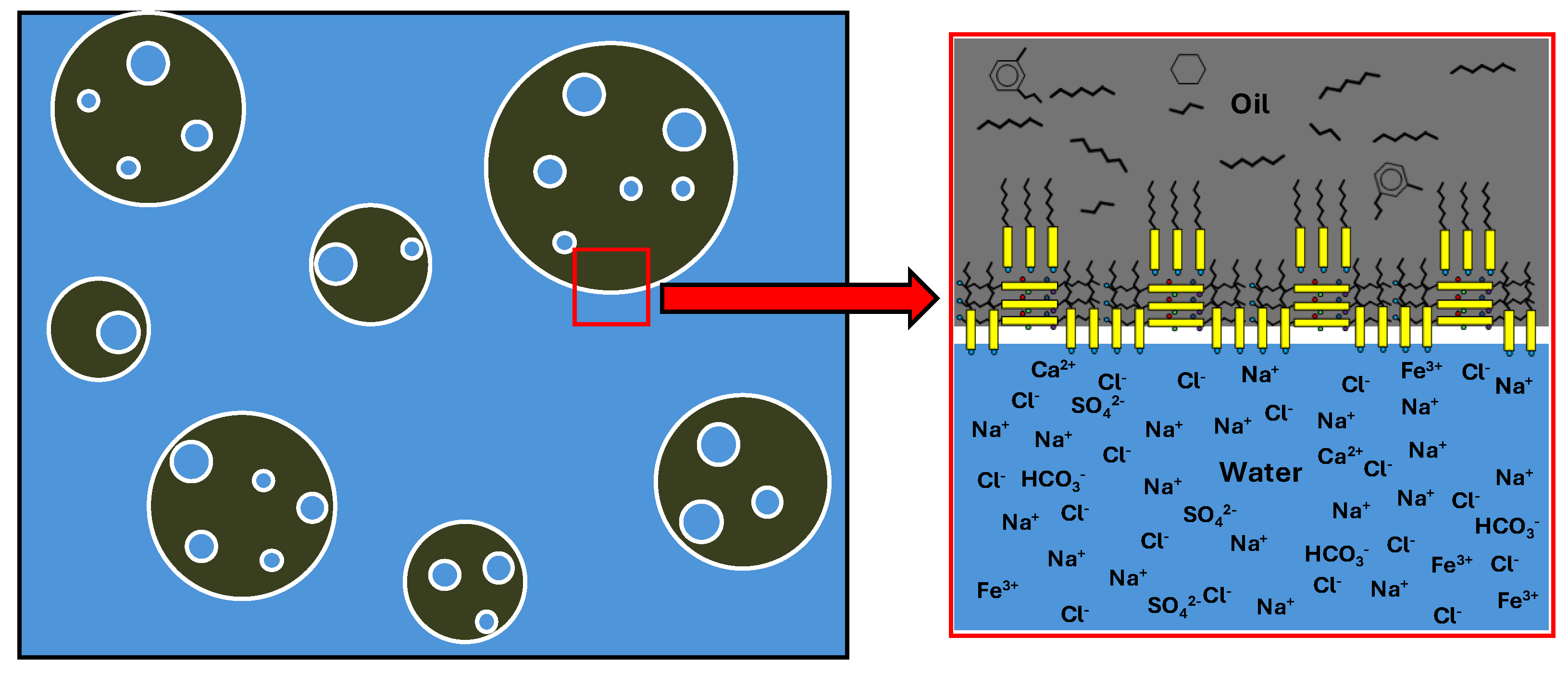

Table 1.
Solvents used for the purification of produced water through emulsion destabilisation and oil recovery.
Table 1.
Solvents used for the purification of produced water through emulsion destabilisation and oil recovery.
| Solvent | CAS Number | Molecular Formula | Density(g/cm³) | Boiling Point (°C) | Molecular Mass (g/mol) |
| 1-Butanol | 71-36-3 | C4H10O | 0.810 | 117.7 | 74.1216 |
| 1-Propanol | 71-23-8 | C3H8O | 0.805 | 97.2 | 60.1 |
| 2-Phenylethanol | 60-12-8 | C8H10O | 1.020 | 218.2 | 122.16 |
| 2-Propanol | 67-63-0 | C3H8O | 0.785 | 82.5 | 60.10 |
| Acetic acid | 64-19-7 | C2H4O2 | 1.045 | 117.9 | 60.05 |
| Acetone | 67-64-1 | C3H6O | 0.790 | 56.0 | 58.08 |
| Acetonitrile | 75-05-8 | C2H3N | 0.787 | 81.6 | 41.05 |
| Benzene | 71-43-2 | C6H6 | 0.879 | 80.1 | 78.11 |
| Butanone | 78-93-3 | C4H8O | 0.805 | 79.6 | 72.11 |
| Chloroform | 67-66-3 | CHCl3 | 1.483 | 61.2 | 119.38 |
| Cyclohexane | 110-82-7 | C6H12 | 0.778 | 80.7 | 84.16 |
| Cyclohexanone | 108-94-1 | C6H10O | 0.948 | 155.6 | 98.14 |
| Decyl oleate | 3687-46-5 | C28H54O2 | 0.866 | 494.8 | 422.727 |
| Dichloromethane | 75-09-2 | CH2Cl2 | 1.325 | 39.75 | 84.93 |
| Diethanolamine | 111-42-2 | C4H11NO2 | 1.097 | 268.8 | 105.14 |
| Diethyl ether | 60-29-7 | C4H10O | 0.713 | 34.6 | 74.12 |
| n-Butyl acrylate | 141-32-2 | C7H12O2 | 0.890 | 145 | 128.17 |
| Dipropylene glycol | 25265-71-8 | C6H14O3 | 1.025 | 231.9 | Unspecified |
| Ethanol | 64-17-5 | C2H6O | 0.789 | 78.5 | 46.07 |
| Ethyl acetate | 141-78-6 | C4H8O2 | 0.902 | 77 | 88.11 |
| Ethylene glycol | 107-21-1 | C2H6O2 | 1.113 | 197.3 | 66.07 |
| Glycerin | 56-81-5 | C3H8O3 | 1.261 | 290 | 92.09 |
| Isobutyl acetate | 110-19-0 | C6H12O2 | 0.871 | 116.5 | 116.16 |
| Isooctane | 540-84-1 | C8H18 | 0.692 | 99.2 | 114.23 |
| Isopropyl myristate | 110-27-0 | C17H34O2 | 0.853 | 192.6 | 270.45 |
| Limonene | 138-86-3 | C10H16 | 0.840 | 175.5 | 136.23 |
| Liquid paraffin | 8012-95-1 | Unspecified | 0.875 | 360 | Unspecified |
| Methanol | 67-56-1 | CH4O | 0.810 | 64.7 | 32.04 |
| N,N-Dimethyl formamide | 68-12-2 | C3H7NO | 0.944 | 153 | 73.09 |
| n-Butyl acrylate | 141-32-2 | C7H12O2 | 0.890 | 145 | 128.17 |
| n-Heptane | 142-82-5 | C7H16 | 0.680 | 98 | 100.2 |
| Petroleum ether | 8032-32-4 | Unspecified | Unspecified | Unspecified | Unspecified |
| Polyethylenglycol 400 | 25322-68-3 | (C2H4O)nH2O | 1.127 | >325 | Unspecified |
| Polypropylene glycol 2000 | 25322-69-4 | (C3H6O)nH2O | 1.002 | >300 | Unspecified |
| Propylene glycol | 57-55-6 | C3H8O2 | 1.036 | 188.2 | 76.09 |
| Tetrachloroethylene | 127-18-4 | C2Cl4 | 1.623 | 121.3 | 165.83 |
| Tetrahydrofuran | 109-99-9 | C4H8O | 0.889 | 65 | 72.11 |
| Toluene | 108-88-3 | C7H8 | 0.864 | 110.6 | 92.14 |
| Vaseline (liquid) | 8009-03-8 | Un specified | 0.840 | 198 | Unspecified |
| Xylene | 1330-20-7 | C8H10 | 0.860 | 137-140 | 106.17 |
Table 2.
Emulsion destabilisation tests for the purification of produced water using solvents.
| 5 ml solvent | 10 ml solvent | 15 ml solvent | 20 ml solvent | 25 ml solvent | ||||||
| Solvent | Cp, ppm | R, % | Cp, ppm | R, % | Cp, ppm | R, % | Cp, ppm | R, % | Cp, ppm | R, % |
| 1-Butanol | 43,3 | 71,1 | 35,6 | 76,3 | 24,4 | 84 | 20,9 | 86 | 15,7 | 89,5 |
| 1-Propanol | 38,5 | 74,3 | 33,1 | 77,9 | 20,8 | 86,1 | 17,1 | 88,6 | 13,1 | 91,3 |
| 2-Phenylethanol | 57,2 | 61,9 | 53,9 | 64,1 | 45,3 | 69,8 | 41,2 | 72,5 | 34,7 | 76,9 |
| 2-Propanol | 40,2 | 73,2 | 34,2 | 77,2 | 22,4 | 85,1 | 18,3 | 87,8 | 14,1 | 90,1 |
| Acetic acid | 82,9 | 44,7 | 77,7 | 48,2 | 74,4 | 50,4 | 69,2 | 53,9 | 53,3 | 64,5 |
| Acetone | 60,4 | 59,7 | 54,2 | 63,9 | 47,8 | 68,1 | 36,2 | 75,9 | 29 | 80,7 |
| Acetonitrile | 79,3 | 47,1 | 75 | 50 | 70,7 | 52,9 | 64,8 | 56,9 | 59,5 | 60,3 |
| Benzene | 43,4 | 71,1 | 31,8 | 78,8 | 24,3 | 83,8 | 15,9 | 89,4 | 11,8 | 92,1 |
| Butanone | 92,2 | 38,5 | 89,2 | 40,5 | 82,7 | 44,9 | 74,5 | 50,3 | 67,2 | 55,2 |
| Chloroform | 13,6 | 90,9 | 10,7 | 92,9 | 9,5 | 93,6 | 5,4 | 96,6 | 2,2 | 98,5 |
| Cyclohexane | 22,4 | 85,1 | 11,1 | 92,6 | 5,6 | 96,3 | 3,2 | 97,9 | 0,7 | 99,5 |
| Cyclohexanone | 27,1 | 81,9 | 15,7 | 89,5 | 11,2 | 92,5 | 5,9 | 96,1 | 2,7 | 98,2 |
| Decyl oleate | 47,9 | 68,1 | 42,7 | 71,5 | 33,9 | 77,4 | 31,1 | 79,3 | 26,7 | 82,2 |
| Dichloromethane | 12,5 | 91,7 | 10,3 | 93,1 | 5,3 | 96,5 | 1,1 | 99,3 | 0,9 | 99,4 |
| Diethanolamine | 62,6 | 58,3 | 58,2 | 61,2 | 48,6 | 67,6 | 41,4 | 72,4 | 37,1 | 75,3 |
| Diethyl ether | 44 | 70,7 | 33,6 | 77,6 | 23,6 | 84,3 | 19,2 | 87,2 | 17,4 | 88,4 |
| Dimethyl sulfoxide | 85,8 | 42,8 | 96,4 | 35,7 | 98,2 | 34,5 | 102,8 | 31,5 | 105,1 | 29,9 |
| Dipropylene glycol | 52,2 | 65,2 | 45,2 | 69,9 | 38,8 | 74,1 | 31,8 | 78,8 | 24,4 | 83,7 |
| Ethanol | 39,4 | 73,7 | 24,6 | 83,6 | 18,3 | 87,8 | 15,8 | 89,5 | 11 | 92,7 |
| Ethyl acetate | 107,9 | 28,1 | 106,2 | 29,2 | 104,3 | 30,5 | 99 | 34 | 94,8 | 36,8 |
| Ethylene glycol | 43,2 | 71,2 | 37,8 | 74,8 | 30,7 | 79,5 | 22,2 | 85,2 | 19,2 | 87,2 |
| Glycerin | 146,7 | 2,2 | 148,3 | 1,1 | 149 | 0,7 | 149,2 | 0,5 | 149,9 | 0,1 |
| Isobutyl acetate | 82,5 | 45 | 74,2 | 50,5 | 65,7 | 56,2 | 57,1 | 61,9 | 48,7 | 67,5 |
| Isooctane | 95,9 | 36,1 | 93,4 | 37,1 | 85,1 | 43,3 | 77,8 | 48,1 | 73,6 | 50,9 |
| Isopropyl myristate | 94,5 | 37 | 89,5 | 40,3 | 84,9 | 43,4 | 78,6 | 47,6 | 72,3 | 51,8 |
| Limonene | 98 | 34,7 | 96,2 | 35,9 | 89,9 | 40,1 | 73,9 | 50,7 | 66,7 | 55,5 |
| Liquid paraffin | 147,1 | 0,2 | 148,1 | 0,1 | 149,7 | 0 | 149,8 | 0 | 150 | 0 |
| Methanol | 34 | 77,3 | 22,3 | 85 | 15,7 | 89,5 | 10,7 | 92,9 | 8,4 | 94,4 |
| N,N-Dimethyl formamide | 45,2 | 69,9 | 36 | 76 | 26,7 | 82,2 | 22,2 | 85,2 | 18,6 | 87,6 |
| n-Butyl acrylate | 87,2 | 29,2 | 97,9 | 31 | 101,6 | 32,3 | 103,5 | 34,7 | 105,9 | 41,9 |
| n-Heptane | 86,7 | 42,2 | 84,5 | 43,7 | 81,2 | 45,9 | 72,7 | 51,5 | 17,9 | 52,1 |
| Petroleum ether | 129,1 | 13,9 | 126,8 | 15,5 | 120,5 | 19,7 | 114,7 | 23,5 | 99 | 34 |
| Polyethylenglycol 400 | 51,1 | 65,9 | 43,5 | 71 | 37,4 | 75,1 | 33,1 | 77,9 | 26,1 | 82,6 |
| Polypropylene glycol 2000 | 52,6 | 64,9 | 47,8 | 68,1 | 41,5 | 72,3 | 34,5 | 77 | 27,2 | 81,9 |
| Propylene glycol | 45,5 | 69,7 | 40,1 | 73,3 | 31,7 | 78,9 | 26,4 | 82,4 | 21,1 | 85,9 |
| Tetrachloroethylene | 0,1 | 99,9 | 0 | 100 | 0 | 100 | 0 | 100 | 0 | 100 |
| Tetrahydrofuran | 0,4 | 99,8 | 0,2 | 99,9 | 0,1 | 100 | 0,1 | 100 | 0 | 100 |
| Toluene | 59,3 | 60,5 | 52,1 | 65,3 | 45,9 | 69,4 | 35,5 | 76,3 | 26,7 | 82,2 |
| Vaseline (liquid) | 145,9 | 2,7 | 146,8 | 2,1 | 148,1 | 1,3 | 149,3 | 0,5 | 149,7 | 0,2 |
| Xylene | 11,6 | 92,2 | 9,4 | 93,7 | 4,4 | 97,1 | 1,1 | 99,3 | 0,9 | 99,4 |
Table 3.
Hansen solubility parameters of de tested solvents, MPa1/2, and ability to destabilise oil emulsions in produced water.
Table 3.
Hansen solubility parameters of de tested solvents, MPa1/2, and ability to destabilise oil emulsions in produced water.
| Number | Solvent | dD | dP | dH | "Effective destabiliser" |
| 1 | Acetonitrile | 15,3 | 18,0 | 6,1 | 0 |
| 2 | Acetic acid | 14,5 | 8,0 | 13,5 | 0 |
| 3 | Isopropyl myristate | 14,4 | 4,0 | 4,3 | 0 |
| 4 | Glycerin | 17,4 | 12,1 | 29,3 | 0 |
| 5 | Tetrachloroethylene | 18,3 | 5,7 | 0,0 | 1 |
| 6 | Toluene | 18,0 | 1,4 | 2,0 | 0 |
| 7 | Diethanolamine | 17,2 | 10,8 | 21,2 | 0 |
| 8 | 2-Phenylethanol | 19,0 | 5,8 | 12,8 | 0 |
| 9 | n-Butyl acrylate | 15,6 | 6,2 | 4,9 | 0 |
| 10 | Dimethyl sulfoxide | 18,4 | 16,4 | 10,2 | 0 |
| 11 | Chloroform | 17,8 | 3,1 | 5,7 | 1 |
| 12 | Acetone | 15,5 | 10,4 | 7,0 | 0 |
| 13 | Ethanol | 15,8 | 8,8 | 19,4 | 1 |
| 14 | Dichloromethane | 18,2 | 6,3 | 6,1 | 1 |
| 15 | Methanol | 15,1 | 12,3 | 22,3 | 1 |
| 16 | Isobutyl methacrylate | 15,8 | 4,9 | 10,7 | 0 |
| 17 | Cyclohexane | 16,8 | 0,0 | 0,2 | 1 |
| 18 | n-Heptane | 15,0 | 1,1 | 2,6 | 1 |
| 19 | Butanone | 16,0 | 9,0 | 5,1 | 0 |
| 20 | Limonene | 17,2 | 1,8 | 4,3 | 0 |
| 21 | Benzene | 18,4 | 0,0 | 2,0 | 1 |
| 22 | 2-Propanol | 15,5 | 6,1 | 16,4 | 1 |
| 23 | 1-Butanol | 16,0 | 5,7 | 15,8 | 1 |
| 24 | Polyethylenglycol 400 | 25,9 | 11,2 | 12,9 | 0 |
| 25 | Decyl oleate | 19,6 | 1,6 | 10,7 | 0 |
| 26 | Ethyl acetate | 15,8 | 5,3 | 7,2 | 0 |
| 27 | Dipropylene glycol | 16,5 | 10,6 | 17,7 | 0 |
| 28 | Propylene glycol | 16,8 | 9,4 | 23,3 | 0 |
| 29 | Polypropylene glycol 2000 | 15,0 | 6,3 | 10,6 | 0 |
| 30 | Vaseline (liquid) | 18,6 | 0,3 | 3,4 | 0 |
| 31 | Liquid paraffin | 16,4 | 0,1 | 0,2 | 0 |
| 32 | Petroleum ether | 14,4 | 0,0 | 0,0 | 0 |
| 33 | Xylene | 17,6 | 1,0 | 3,1 | 1 |
| 34 | N,N-Dimethyl formamide | 17,4 | 13,7 | 11,3 | 1 |
| 35 | Isooctane | 15,2 | 0,0 | 0,0 | 0 |
| 36 | Diethyl ether | 14,5 | 2,9 | 5,1 | 1 |
| 37 | Tetrahydrofuran | 16,8 | 5,7 | 8,0 | 1 |
| 38 | Ethylene glycol | 17,0 | 11,0 | 26,0 | 1 |
| 39 | Cyclohexanone | 17,8 | 6,3 | 5,1 | 1 |
| 40 | 1-propanol | 16,0 | 6,8 | 17,4 | 1 |
Table 4.
HSP and radii of the three solubility spheres of produced water.
| Hansen Parameters | L Sphere | LH Sphere | H Sphere |
| Dispersion, δD | 16,6 | 16,9 | 14,9 |
| Polarity, δP | 5,1 | 9,2 | 11,4 |
| Hydrogen bonding, δH | 1,6 | 13,7 | 26,0 |
| Radius, R0 | 5,5 | 5,2 | 4,1 |
Disclaimer/Publisher’s Note: The statements, opinions and data contained in all publications are solely those of the individual author(s) and contributor(s) and not of MDPI and/or the editor(s). MDPI and/or the editor(s) disclaim responsibility for any injury to people or property resulting from any ideas, methods, instructions or products referred to in the content. |
© 2024 by the authors. Licensee MDPI, Basel, Switzerland. This article is an open access article distributed under the terms and conditions of the Creative Commons Attribution (CC BY) license (http://creativecommons.org/licenses/by/4.0/).
Copyright: This open access article is published under a Creative Commons CC BY 4.0 license, which permit the free download, distribution, and reuse, provided that the author and preprint are cited in any reuse.


