Submitted:
04 December 2024
Posted:
04 December 2024
You are already at the latest version
Abstract
As environmental awareness grows, hydrodesulfurization (HDS) catalysts have become crucial in petroleum refining, yet their use results in oil-laden waste that poses environment risks and complicates subsequent treatment. Efficient oil removal is thus critical for processing spent catalysts. This study systematically compares three de-oiling methods: extraction, chemical thermal washing, and pyrolysis, to identify the optimal de-oiling method. In the experiments, the extraction achieves 94.12% oil removal rate at a liquid-to-solid ratio of 10 mL/g and 45℃ in 60 minutes, maintaining around 90% efficiency after five cycles of solvent recovery. The chemical thermal washing achieves oil removal rate of 96.26% after 4 hours at 90℃, with 0.15 wt.% SDS, 3.0 wt.% NaOH, and a liquid-to-solid ratio of 10 mL/g. The heavy oil emulsion is then decomposed with 4% CuO and 5% H2O2. The pyrolysis method removes 96.19% of oil at 600℃ in 60 minutes. While the extraction and chemical thermal washing methods are effective, they produce wastewater, raising environmental concerns. In contrast, the pyrolysis method is more environmentally friendly. SEM, EDS, and FT-IR analyses show that after oil removal, the metal structures on the alumina support of the spent HDS catalyst are clearly exposed, facilitating the subsequent recovery of valuable metals.
Keywords:
Resource Recycling
; Environmental Protection
; Oil Removal Efficiency
; Extraction
; Chemical Thermal Washing
; Pyrolysis
1. Introduction
As global awareness of environmental protection continues to grow, automotive fuel specifications and atmospheric emission standards are becoming increasingly stringent. In order to meet these ever-tightening requirements, the role of hydrodesulfurization (HDS) catalysts in the petroleum refining process has become increasingly important. These catalysts are primarily used to remove impurities such as sulfur, nitrogen, and metals from crude oil [1], thereby producing cleaner energy. However, after repeated cycles of use, catalysts gradually lose their activity due to sintering, heavy metal poisoning, coke formation, sulfide and residual oil deposition, or wear and loss of active sites [2]. Eventually, they turn into waste catalysts. It is estimated that the global petrochemical industry generates over 170,000 tons of waste HDS catalysts annually [3]. The surfaces of these spent catalysts are often covered with a large amount of crude oil components and heavy metals, which pose a significant threat to the environment and human health. As a result, they are classified as hazardous solid waste by countries like China and the United States [4]. Therefore, the safe disposal of oil-containing waste HDS catalysts is becoming particularly urgent and important.
At the same time, these spent catalysts contain more valuable metals than natural minerals, such as aluminum (Al), nickel (Ni), molybdenum (Mo), and vanadium (V) [3]. In recent years, with the rapid rise of new energy companies, the development of secondary nickel resources has become a hot topic [3]. Thus, processing these spent catalysts and recovering the valuable metals not only helps protect the environment but also has significant economic implications. Traditional methods for handling spent catalysts include transporting them to metal recycling plants, commercial landfills, or direct incineration [5]. Regardless of the method used, the oil removal process is always indispensable. There are two main reasons for this: on the one hand, the residual oil in the spent catalyst contains toxic substances such as aromatic hydrocarbons, resins, asphaltenes, and trace metals [6]. Removing the oil helps reduce environmental pollution to air, water, and soil during landfill disposal. On the other hand, the crude oil attached to the spent catalyst surface hinders the contact between the solid surface and the liquid phase, thus affecting the effectiveness of recovering precious metals through chemical leaching.
Currently, treatment technologies for oil-containing solid waste mainly fall into two categories: harmless treatment and resource utilization. Harmless treatment methods include solidification [7], oxidation-reduction [8], biodegradation [9], and incineration [10], aimed at reducing environmental pollution and health risks. Resource utilization methods include physical separation [11], pyrolysis [12], chemical thermal washing [1], ultrasonic treatment [13], and solvent extraction [6], focusing on recovering valuable components from waste and promoting resource recycling. Given the high oil content in spent catalysts, the industry tends to favor resource utilization methods to maximize resource recovery and utilization. Therefore, this paper combines the characteristics of waste HDS catalysts with market demand and investigates three common oil-removal methods: extraction, chemical washing, and pyrolysis. The extraction method extracts oil from the spent catalyst using an extractant, recycles the solvent, and reuses it. Chemical washing combines alkali and surfactants to remove the oil attached to the surface of the spent catalyst through a thermal washing process. Pyrolysis is conducted in an inert atmosphere using a tube furnace, where high-temperature pyrolysis reactions produce pyrolysis oil and gas. This paper aims to compare the effectiveness of these three methods and explore the most efficient oil removal technique, thereby achieving high-efficiency recovery of crude oil from the surface of spent catalysts and promoting resource utilization. Finally, SEM, EDS, and FT-IR characterization techniques are used to analyze the spent catalysts before and after treatment, assessing whether the oil removal process facilitates the subsequent recovery of valuable metals.
2. Materials and Methods
2.1. Materials and Chemicals
The raw material used in this study is spent hydrodesulfurization catalyst (V-Mo-Ni/Al2O3, HDS), which has a cylindrical structure and is black due to the presence of crude oil and coke on its surface. Its oil content is approximately 26%. Acetone (>99.5%), dichloromethane (AR), toluene (AR), p-xylene (AR), ethyl acetate (>99%), petroleum ether (AR), sodium hydroxide (NaOH), sodium dodecyl sulfate (SDS) are all of analytical reagent grade and are purchased from Aladdin Chemical Reagent Co., Ltd. All designated concentrations of solutions are prepared using deionized water.
2.2. Experimental Procedure
2.2.1. Extraction Method
5 g of spent HDS catalyst is added to a flask containing solvent, and seal the flask with plastic wrap. Then, place the flask in a water bath and perform the de-oiling experiment under magnetic stirring conditions. After de-oiling, use a circulating water vacuum pump to achieve liquid-solid separation, and dry the separated solid in an oven at 120°C for 12 hours. The experimental conditions, including liquid-solid ratio, temperature, time, stirring speed, and particle size of the spent catalyst, is studied to determine the optimal extraction. The extract is separated from the solvent and crude oil through distillation equipment (Figure 6a). The separated solvent is reused to clean the spent catalyst, and the separated oil is recovered.
2.2.2. Chemical Hot Washing Method
5 g of waste HDS catalyst is added to a beaker containing an alkaline SDS solution, and the beaker is sealed with plastic wrap. Then, the beaker is placed in a water bath and the desorption experiment is conducted under magnetic stirring conditions. After desorption, liquid-solid separation is achieved using a circulating water vacuum pump, and the solid obtained is dried at 120℃ in an oven for 12 hours. The experimental conditions of SDS concentration, NaOH concentration, liquid-solid ratio, temperature, time, stirring speed, and the size of the waste catalyst are studied to determine the optimal extraction conditions. In addition, since the oil-free alkali solution obtained after desorption contained a large number of alkanes and cannot be discharged directly, a method of adding 4% CuO and 5% H2O2 at 50°C for 1 hour is used to catalyze the degradation of the emulsified liquid [14].
2.2.3. Pyrolysis Method
100 g of hydrodesulfurization waste catalyst and place it in a quartz boat, which is then inserted into the steel tube of the tube furnace. The carrier gas delivery pipe, steel tube, and condensation purification device are connected, and N₂ is continuously introduced at a flow rate of 200 mL/min. After the air in the system is purged, the N₂ flow rate is adjusted to 100 mL/min. The quartz boat is quickly pushed into the temperature-controlled reaction zone, and the pyrolysis reaction begins. The pyrolysis reaction setup is shown in Figure 1. First, the heating rate is set to 10°C/min, and the pyrolysis time is set to 60 min. Then, pyrolysis is carried out at temperatures of 300°C, 400°C, 500°C, 600°C, 700°C, and 800°C to determine the optimal pyrolysis temperature conditions. After finding the optimal temperature, pyrolysis continues under N₂ conditions, maintaining a heating rate of 10°C/min, and different residence times (30 min, 60 min, 90 min, and 120 min) are set to determine the optimal pyrolysis time. The oil produced from the pyrolysis is then recovered.
2.3. Oil Removal Efficiency Determination
The dried waste HDS catalyst was weighed, and the oil removal efficiency could be calculated using Equation (1)[1].
where is the oil removal efficiency of the waste HDS catalyst, %; is the initial mass of the waste HDS catalyst, g; and is the mass of the residual substance of the spent HDS catalyst after oil removal, g.
2.4. Characterization
The morphology of the spent HDS catalyst before and after treatment is characterized using a scanning electron microscope (SEM, Smart Lab 9kw, Japan) and energy dispersive X-ray spectroscopy (EDS, Smart Lab 9kw, Japan). The functional groups of the surface-attached crude oil on the spent HDS catalyst before and after treatment are characterized using a Fourier transform infrared spectrometer (FT-IR, VERTEX 70, Germany).
3. Results and Discussion
3.1. Optimization of Extraction Process Conditions
3.1.1. Selection of Extraction Agent
This section comprehensively considers the volatility, toxicity, and cost of solvents, and selects six commonly used pure solvents with similar polarity and good solubility to residual oil as oil extraction agents. These solvents are acetone, dichloromethane, toluene, p-xylene, isobutyl acetate, and petroleum ether. The oil extraction experiments are conducted with these solvents under the conditions of 50°C, 60 minutes, a solid-to-liquid ratio of 10:1, a stirring speed of 500 rpm/min, and an average particle size of 47.419 μm, and the results are shown in Figure 2.
From Figure 4, the cleaning efficiency of the solvent in descending order is: Toluene > Para-Xylene > Methylene chloride > Isobutyl Acetate > Acetone > Petroleum ether. Generally, the cleaning efficiency of the solvent increases as its polarity decreases (Table 1), because the main component of the oil on the spent HDS catalyst is non-polar, and according to the principle of similar dissolution, the lower the solvent polarity, the higher the cleaning efficiency. Although petroleum ether has a low polarity, its cleaning efficiency is low because the light oil components in petroleum ether have a higher solubility in the spent HDS catalyst, but the light oil components on the spent HDS catalyst are less, resulting in low cleaning efficiency. In addition, the selection of the solvent not only needs to consider its polarity, but also its aromaticity. The analysis of the oil recovered by gas chromatography shows that the crude oil contains a large proportion of aromatic hydrocarbons. Toluene is more similar in composition to the aromatic hydrocarbons and asphaltenes in the crude oil than to the other solvents, thus having better affinity for the crude oil and higher cleaning efficiency. Therefore, Toluene is selected as the cleaning solvent after comprehensive consideration.
3.1.2. Optimization of Oil Removal Efficiency
In order to further improve the efficiency of toluene removal from waste HDS catalysts, the effects of liquid-to-solid ratio, temperature, time, stirring speed, and catalyst particle size on the oil removal efficiency are studied.
In the extraction process, the amount of solvent used has a decisive effect on the extraction efficiency. As shown in Figure 5a, the oil removal efficiency of the waste catalyst increases as the L/S ratio increases. This is because the larger the L/S ratio, the greater the solubility of oil in the extraction solvent, thereby increasing the amount of recovered oil [16]. When the L/S ratio increases from 4:1 to 8:1, the oil removal rate increases linearly, but the rate of oil removal efficiency increase gradually decreases after exceeding 8:1. Therefore, considering extraction efficiency and extraction cost, the optimal liquid-to-solid ratio of 10:1 is selected.
Figure 5b shows the effect of temperature on oil removal efficiency. In the range of 25°C to 45°C, as the temperature increases, the oil removal efficiency of the spent HDS catalyst improves, with a noticeable increase. This is because: (1) the increase in temperature reduces the viscosity of the oil, improving the fluidity of the crude oil components; (2) the diffusion of crude oil components and the Brownian motion of solvent molecules accelerate with the temperature increase, leading to an increased mass transfer rate of crude oil molecules from the solid phase to the liquid phase; (3) the adhesion force between catalyst particles and crude oil molecules weakens as temperature increases, allowing more hydrocarbons to dissolve in the solvent[17]. However, as the temperature continues to rise, a significant decrease in oil removal efficiency occurs, and the amount of toluene recovered by filtration decreases. Therefore, the reason for the gradual decrease in oil removal efficiency with increasing temperature may be the volatilization of toluene, causing the sample not to fully contact with toluene under these conditions. Considering safety, equipment, and energy consumption in the de-oiling process, the optimal reaction temperature is selected as 45°C.
Figure 5c demonstrates the time-dependent variation in oil removal efficiency. In the range of 30 min to 60 min, as the time increases, the oil removal efficiency of the spent HDS catalyst continuously improves, reaching its maximum oil removal rate at 60 min. The reasons may be as follows: when the contact time is short, the reaction process is incomplete, leading to a low oil removal rate; as the time increases, the spent catalyst and toluene have more sufficient contact, and the oil removal rate continues to improve with good separation efficiency. However, if the reaction time is extended further, the oil removal rate decreases. This is because, by 60 min, the solvent has essentially reached a saturated state, and the extraction process reaches equilibrium. As time increases, the oil removed from the catalyst surface is re-adsorbed, which leads to a reduction in oil removal efficiency. Therefore, the optimal extraction time is selected as 60 min.
Figure 5d depicts the impact of stirring speed on oil removal efficiency. The stirring speed determines the contact efficiency between the catalyst and the solvent. When the stirring speed is too slow, the contact between the catalyst and the solvent is insufficient, which is equivalent to only part of the solvent participating in the cleaning. Increasing the speed will increase the contact rate between the crude oil and the solvent molecules, thereby increasing the mass transfer rate of the catalyst to the solvent. However, at too high a stirring rate, the contact time between crude oil and solvent molecules is short, and there is not enough time for extraction. The solvent extraction efficiency reaches its maximum at 300 rpm, so 300 rpm is selected as the optimal stirring speed.
Figure 5e presents the influence of particle size on oil removal efficiency. By comparing the oil removal efficiency of different particle sizes of waste HDS catalyst, it can be concluded that grinding the waste HDS catalyst can significantly improve the oil removal efficiency of HDS catalyst. This is because the particle size of the waste HDS catalyst is reduced, exposing more oil-containing pores, thereby improving the oil removal efficiency. However, when the particle size of the waste HDS catalyst is less than D50 of 47.416 µm, the oil removal efficiency does not further improve, but slightly decreases, because the particle size of the catalyst is too small, exposing the low oil content or uncontaminated parts, causing the oil to re-adsorb onto the catalyst [18]. It has also been reported that small particles bind to the colloid in oil more firmly. Therefore, D50 of 47.416 µm is chosen as the suitable particle size of the waste catalyst.
3.1.3. Solvent Recycling
The most prominent advantage of solvent cleaning waste HDS catalyst is the ability to recover oil resources and solvents during the cleaning process, achieving the recycling of resources, reducing costs, and reducing environmental pollution. After extraction, the waste catalyst and extraction liquid are separated by filtration, and the solid part is dried for use in the metal extraction stage, allowing it to be further resourcefully utilized. The extraction liquid is then separated by a distillation device (Figure 6a) to recover the solvent and crude oil. The color of the recovered oil is brownish yellow, and the deeper the color, the higher the double bond content in the crude oil, suggesting that the recovered oil contains higher amounts of aromatic hydrocarbons and asphaltenes.
The recovered solvent was used in the experimental study of recycling washing oil from spent catalysts, with the lost solvent being supplemented to keep the L/S ratio at 10:1 throughout the washing process. The cyclic experiment was conducted at 45°C, 60 min, 300 rpm/min, and with the D50 of the waste catalyst being 47.416 µm. The experimental results, as shown in Figure 4b, indicate that after five cycles, the extraction efficiency of toluene for the spent HDS catalyst still remains at around 90%, which indicates that recycling the solvent to recover oil from spent catalysts is economically feasible. The recovered solvent volume is shown in red in Figure 6b, with a recovery rate ranging from 88 to 94%. The solvent may be lost during mixing, filtration, and transferring liquids [19]. Therefore, to reduce the loss of solvent, it is possible to optimize the sealing of equipment and simplify the process flow in practical operation, and reduce the frequency of liquid transfer. By doing so, the cleaning cost can be further controlled.
3.2. Optimization of Chemical Thermal Washing Process Conditions
3.2.1. Optimization of Oil Removal Efficiency
In order to further improve the efficiency of chemical thermal washing in removing oil from spent HDS catalyst, the effects of SDS concentration, NaOH concentration, liquid-solid ratio, temperature, time, stirring speed, and catalyst particle size on oil removal efficiency are studied, as shown in Figure 5.
The oil removal efficiency from waste catalysts is closely related to the interfacial tension, which is influenced by the concentrations of SDS, NaOH, liquid-to-solid ratio, temperature, time, stirring speed, and the particle size of the waste catalyst. Figure 7a illustrates the impact of SDS concentration on oil removal efficiency. The oil removal efficiency first increases and then decreases, reaching a maximum at an SDS concentration of 0.15 wt.%. This is because when the surfactant concentration reaches the critical micelle concentration, micelles are formed in the solution, which solubilize the oil components, making previously insoluble oil soluble. As the concentration increases, the solubilizing effect becomes more pronounced. The surfactant also helps to lift the oil from the solid surface [17,20]. However, when the concentration becomes too high, the solubilizing effect of the surfactant reaches saturation. At this point, interactions occur between the hydrophobic groups, forming a bilayer adsorption on the surface of the spent catalyst [17,21]. The mixed system transitions into emulsification, which results in a decrease in de-oiling efficiency. Moreover, excessively high concentrations not only reduce oil removal efficiency but also lead to waste of chemicals, increasing costs. Therefore, 0.15 wt.% is selected as the optimal SDS concentration.
Figure 7b displays the effect of NaOH concentration on oil removal efficiency, which has a similar trend to that of SDS. This is likely because adding an appropriate amount of NaOH can enhance the activity of the surfactant, reduce the oil-water interfacial tension, and neutralize the acidic substances in the waste HDS catalyst, which helps separate the oil, gums, and coke from the catalyst, thus improving the oil removal rate [22]. However, an excessive amount of NaOH can cause the contact angle to shift from water-wet to oil-wet, blocking the water channels between the estimated surface and the oil phase, which reduces the oil removal efficiency. Excessive NaOH concentration not only lowers the oil removal efficiency but also leads to reagent waste and increased costs. Thus, the appropriate ratio of alkali to surfactant is key. Considering these factors, 3 wt.% is chosen as the optimal NaOH concentration.
Figure 7c indicates that the liquid-to-solid ratio significantly affects oil removal. The oil removal efficiency of the waste HDS catalyst increases with the L/S ratio. A higher L/S ratio increases the solubility of oil in the solvent, thereby increasing the amount of oil recovered. When the L/S ratio increases from 4:1 to 8:1, the oil removal rate increases linearly. However, when the L/S ratio exceeds 8:1, the growth rate of oil removal efficiency gradually slows down. Therefore, considering both washing efficiency and cost, an L/S ratio of 10:1 is selected.
Figure 7d shows that within the range of 25°C to 90°C, the oil removal efficiency of the waste HDS catalyst increases with temperature, with a noticeable increase. This is because increasing the temperature enhances molecular motion, increases the activity of the washing agent, reduces hydration, and facilitates micelle formation. It also accelerates the reaction rate and decreases the viscosity of the crude oil, increasing the flowability of the crude oil components, reducing the adhesion between the crude oil and catalyst, and improving the contact between the washing agent and catalyst, thereby enhancing the oil removal efficiency [17]. When the temperature is between 90°C and 95°C, oil removal efficiency increases but at a slower rate, and higher temperatures result in greater energy consumption. Therefore, considering these factors, the optimal washing temperature is selected as 90°C.
Figure 7e demonstrates that as the washing time increases, the oil removal efficiency continues to improve. This is because the viscosity of the residual oil attached to the waste HDS catalyst is high. If the cleaning time is too short, the catalyst cannot be fully dispersed in the cleaning solution, and the residual oil does not come into complete contact with the washing agent, resulting in poor oil removal. As the washing time increases from 0.5 hours to 4 hours, the waste HDS catalyst is more effectively stirred and dispersed, allowing for better contact between the cleaning agent and the waste catalyst, significantly improving oil removal efficiency. However, as the washing time increases further, the dispersion of the waste catalyst in the cleaning solution reaches saturation, and the improvement in oil removal efficiency becomes less noticeable. Extended washing times not only fail to significantly increase oil removal but also increase energy consumption. Therefore, considering the optimal cleaning time, 4 hours is selected.
The impact of stirring speed on oil removal efficiency is shown in Figure 7f. As the stirring speed increases, the oil removal efficiency improves. Increasing the stirring speed helps promote the full contact between the waste HDS catalyst and the washing agent, facilitating the action of the surfactant to lift and peel off the oil, thus improving the oil removal rate. However, excessively high stirring speeds not only increase energy costs but may also lead to the formation of water-in-oil emulsions, affecting oil-water separation [23]. Considering both oil removal efficiency and cost, an optimal stirring speed of 800 rpm/min is selected.
Figure 7g illustrates that crushing used HDS catalysts can significantly improve the de-oiling efficiency of the HDS catalyst. This is because the reduction in particle size of the used HDS catalyst exposes more oil in the pores, thus enhancing the de-oiling efficiency. When the particle size of the used HDS catalyst is smaller than D50 = 47.416 µm, the de-oiling efficiency does not increase further. Instead, it slightly decreases, as catalysts with too small a particle size expose areas with low oil content or non-contaminated sites, causing oil to re-adsorb onto the catalyst. It has also been reported that smaller particles bind more strongly with the colloids in the oil. Therefore, D50=47.416 µm is chosen as the suitable particle size for the used catalyst.
3.2.2. Wastewater Treatment
The de-oiling alkali solution is an emulsion of heavy oil containing a large number of alkanes that cannot be directly discharged, so the emulsion is decomposed by the catalytic degradation method using CuO. The specific operation is as follows: add 4% CuO and 5% H2O2 to the de-oiling alkali solution, heat to 50℃, and react for 1 hour. The infrared spectrum of the emulsion is shown in Figure 8. The infrared spectrum analysis of the emulsion is as follows [24]: The broad absorption peak at 3447 cm-1 is the stretching vibration of -OH, -NH in alcohol, phenol, and water; the absorption peak at 1396 cm-1 is the asymmetric bending vibration of -CH3; the absorption peak at 1110 cm-1 is the bending vibration of alkane. The sample after the emulsion is degraded with NaOH is consistent with the peak of pure NaOH solution, and the characteristic peak of crude oil is basically eliminated, indicating that the catalytic degradation can effectively treat the emulsion.
3.3. Optimization of Pyrolysis Process Conditions
Figure 9a shows the oil removal efficiency at different pyrolysis temperatures, Figure 6a shows the oil removal efficiency at different pyrolysis temperatures. The results indicate that as the pyrolysis temperature increases, the oil removal efficiency rises rapidly, but the rate of increase slows down after 500°C. When the pyrolysis temperature reaches 600°C, the yield of pyrolysis oil decreases, likely because above this temperature, liquid products further crack into small molecule gases, leading to a decrease in yield and an increase in pyrolysis gas. Therefore, 600°C is determined as the optimal pyrolysis temperature. Figure 9b shows the effect of different pyrolysis times on oil removal efficiency at 600°C. It can be seen that as the pyrolysis time increases, the oil removal efficiency first increases and then stabilizes. The extended pyrolysis time promotes the generation of pyrolysis gas, which results in a decrease in the yield of pyrolysis oil, so 60 minutes is chosen as the optimal pyrolysis time.
Oil removal by pyrolysis demonstrates high efficiency due to its ability not only to remove residual oil from the surface of spent catalysts but also to effectively clean the oil trapped within the catalyst's pores. Additionally, the pyrolysis process generates pyrolysis oil, enabling the recovery of residual oil and laying the foundation for the secondary high-value utilization of waste oil. Characterization of the oil-removed spent catalysts allows for the evaluation of both the oil removal efficiency and changes in pore structure, thereby creating favorable conditions for the subsequent efficient recovery of strategic metals from the spent catalysts.
3.4. Characterization
3.4.1. SEM and EDS
The morphology of the waste HDS catalyst before and after oil removal by different methods was analyzed using SEM (Figure 10). It can be seen from Figure 10a1 that the dispersibility of the waste HDS catalyst before oil removal is poor, and the surface is completely covered with oil (Figures 10a2, 10a3), resulting in a significantly larger particle size of the waste HDS catalyst before oil removal (Figure 10a1) than the particle size of the waste HDS catalyst after oil removal by the three methods (Figures 10b1, 10c1, 10d1). After being treated by the three oil removal methods, the crude oil on the surface of the waste HDS catalyst and in the pores was effectively removed (Figures 10b2, 10b3, 10c2, 10c3, 10d2, 10d3), and the dispersibility of the waste HDS catalyst was significantly improved (Figures 10b1, 10c1, 10d1). However, it can be clearly seen from Figures 10b1, 10c1, and 10d1 that the dispersibility of the waste HDS catalyst after pyrolysis method is significantly better than that of the waste HDS catalyst after extraction method and chemical thermal washing method treatment. From Figure 10b2, 10b3, 10c2, 10c3, 10d2, and 10d3, it can be seen that the amount of residual oil on the surface of the waste HDS catalyst after hot-alkali treatment is less than that after extraction treatment and chemical thermal desorption treatment, which is more favorable for the subsequent leaching of valuable metals. Therefore, in the process of removing oil from waste HDS catalysts, pyrolysis method is superior to extraction method and chemical thermal washing method. Furthermore, the three desorption methods can make the metal structure loaded on the alumina support of the spent HDS catalyst clearly exposed (Figures 10b3, 10c3, 10d3), which makes it easier for subsequent valuable metal chemical recovery.
The surface element composition of the spent HDS catalyst before and after desorption was analyzed by EDS. It is reported that the HDS catalyst is composed of active metal-loaded on Al2O3 carrier, such as Ni, V, Mo, etc. [25]. Therefore, the cleaned catalyst should consist of elements such as Al, Ni, V, Mo, etc. However, as shown in Figure 11a, the elements mainly contained in the oil-contaminated spent HDS catalyst are C, O, Al, S, Fe, and Ca. These are mostly elements present in crude oil, of which C and O are the hydrocarbons in crude oil, S, Fe, and Ca are elements carried by crude oil. Therefore, the content of the elements that should be present in the catalyst, such as Al, O, Ni, V, etc., is very low. However, after the three desorption methods were applied, the content of C, Ca, and S in the catalyst was significantly reduced or even disappeared, indicating that the three methods can effectively remove the crude oil on the surface of the spent catalyst. After the crude oil was removed, as shown in Figure 11b, 11c, and 11d, the Al2O3 carrier and the active metal were exposed, and the content of surface elements such as Al, O, Ni, V, etc. increased significantly. However, the total amount of valuable elements on the surface of the spent catalyst after being treated by extraction method and chemical thermal desorption method is less than that exposed by pyrolysis method, therefore, among the three methods of oil removal, the pyrolysis method is superior to the other two methods. Therefore, among the three methods of oil removal, the pyrolysis method is superior to the other two methods.
3.4.2. FT-IR
Figure 12 shows the FT-IR spectra of three different methods of oil removal before and after treatment of waste HDS catalysts. The red line represents the infrared spectrum of the oil-containing waste HDS catalyst before treatment, while the blue, purple, and green lines represent the infrared spectra of the waste HDS catalyst after extraction, chemical thermal washing, and pyrolysis method, respectively. There is a broad absorption band in the range of 3500~3200cm-1, which may be the stretching vibration absorption peak of -OH [26,27]. The peaks at 2922cm-1 and 2852cm-1 correspond to the asymmetric and symmetric stretching vibrations of -CH2 [27,28]. The absorption peak at 1626cm-1 is the symmetric stretching of the -COO group, indicating that there are more asphaltene in the oil-containing waste HDS catalyst [29,30]. The absorption peaks at 1458cm-1 and 1378cm-1 are due to the symmetric and asymmetric bending vibrations of -CH3 [28,29]. The absorption peak at 1104cm-1 is the stretching vibration of Al-O-Al, which is a structure that is easy to form hydrogen bonds with oil molecules [31]. There are also two absorption bands in the range of 900~600cm-1, which may be the deformation vibration of C-H in aromatic rings, further proving the presence of aromatic compounds [32,33].
After toluene extraction, the intensity of the asymmetric (C-H, 2922 cm-1) and symmetric (C-H, 2852 cm-1) stretching vibrations of the catalyst is significantly reduced, indicating that a large amount of alkane substances is removed. The intensity of the symmetric stretching vibration of the -COO group (C=O, 1626 cm-1) is weakened, indicating that there was still a large amount of asphalt pitch in the treated oil-containing waste HDS catalyst. Meanwhile, the peaks at 1458 cm-1 and 1378 cm-1 almost disappeared.
After being treated by chemical thermal washing, the stretching vibration absorption peak of -OH (3500~3200 cm-1) became narrower, indicating that part of the hydrocarbons and water are removed. The intensity of the symmetric stretching vibration of the -COO group (C=O, 1626 cm-1) is weakened, indicating that there is still a part of asphalt pitch in the treated oil-containing waste HDS catalyst. Meanwhile, the absorption peak near 1104 cm-1 is also significantly weakened. Furthermore, the two absorption bands in the range of 900~650 cm-1 almost disappeared.
After being treated by pyrolysis, the stretching vibration absorption peaks of -OH (3500~3200 cm-1) in the catalyst were significantly narrower, indicating that a large number of hydrocarbons and water are removed. Meanwhile, the asymmetric (at 2922 cm-1) and symmetric (at 82852 cm-1) stretching vibration peaks of C-H almost disappeared, indicating that alkanes are removed in large quantities. The symmetric stretching intensity of C=O (1626 cm-1) in the -COO group is significantly weakened, indicating that the pyrolysis method also has an effect on asphalt. The absorption peak around 1104 cm-1 is also significantly weakened. In addition, the peaks at 1458 cm-1 and 1378 cm-1 and the two absorption bands in the range of 900 to 650 cm-1 were almost absent.
These changes indicate that the three different treatment methods can remove the crude oil components in the spent HDS catalyst, thereby exposing the metal structure loaded on the alumina more clearly, which will facilitate the subsequent recovery of valuable metals. Especially, the efficiency of the pyrolysis method in oil removal is more prominent.
4. Conclusion
In this study, based on the characteristics of spent HDS catalysts and market demand, three oil removal methods were selected: extraction, chemical thermal washing, and pyrolysis. The effectiveness of these methods in removing crude oil adhered to the surface of spent HDS catalysts was investigated. Experimental results show that all three methods can effectively remove the crude oil adhered to the surface of the spent catalyst. Specifically, the extraction method achieves an oil removal rate of 94.12% when using a liquid-to-solid ratio of 10 ml/g and extracting at 45°C for 60 minutes. After five cycles of solvent recovery, the oil removal efficiency remains around 90%. The chemical thermal washing method, conducted at 90°C with 0.15 wt.% SDS, 3.0 wt.% NaOH, and a liquid-to-solid ratio of 10 ml/g for 4 hours, achieves an oil removal rate of 96.26%. Subsequently, heavy oil emulsions are degraded using 4% CuO and 5% H₂O₂. The pyrolysis method achieves an oil removal efficiency of 96.19% under the conditions of 600°C and 60 minutes.
However, while the extraction and chemical thermal washing methods show outstanding oil removal efficiency, they generate a large amount of waste liquid during the process, increasing the complexity and cost of subsequent treatment, and may lead to secondary pollution. In contrast, the pyrolysis method not only avoids the generation of large amounts of waste liquid during the oil removal process, making it more environmentally friendly, but also allows the oil components to be fractionated and pyrolyzed at different temperature ranges, improving the efficiency of resource recovery. In addition, SEM, EDS, and FT-IR analyses before and after the treatment of the spent HDS catalyst confirm that all three methods can effectively remove the crude oil adhered to the surface of the spent catalyst. The pyrolysis method stands out in crude oil recovery. During the pyrolysis process, the dispersibility of the spent catalyst is significantly improved, and the metal structure loaded on alumina is clearly exposed, providing more favorable conditions for the subsequent chemical recovery of valuable metals, thus simplifying the recovery process.
Author Contributions
“writing—original draft preparation, X.H.; writing—review and editing, J.C. and J.W.; software, W.W.; formal analysis, J.C.; supervision, Z.Y.; project administration, F.X.; funding acquisition, G.T. and S.S. All authors have read and agreed to the published version of the manuscript.”
Data Availability Statement
The original contributions of this study are listed in the article. For further inquiries, please contact the corresponding author reasonably.
Acknowledgments
This work was supported by the National Key Research and Development Program of China (2019YFC1907504; 2020YFC1909102).
Conflicts of Interest
The authors declare no conflicts of interest.
References
- Yang, Y.; Xu, S; Li, Z.; Wang, J.L.; Zhao, Z.W.; Xu, Z.H. Oil removal of spent hydrotreating catalyst CoMo/Al2O3 via a facile method with enhanced metal recovery[J]. Journal of hazardous materials 2016, 318: 723-731. [CrossRef]
- Wang, J.Z.; Wang, S.N.; Olayiwola, A.; Yang, N.; Liu, B.; Weigand, J.J.; Wenzel, M.; Du, H. Recovering valuable metals from spent hydrodesulfurization catalyst via blank roasting and alkaline leaching[J]. Journal of Hazardous Materials, 2021, 416: 125849. [CrossRef]
- Chen, Y.X.; Wu, X.S.; Guan, W.J.; Xiao, S.Y.; Fang, K.Y.; Qing, J.L.; Xie, R.; Wu, S.X.; Li, Q.G.; Cao, Z.Y.; Wang, M.Y.; Zhang, G.Q. Efficient recovery of all valuable metals from spent HDS catalysts: Based on roasting mechanisms for enhanced selective leaching and separation[J]. J. Environ. Chem. Eng, 2024, 12(5): 113485. [CrossRef]
- Le, M.N.; Lee, M.S. A review on hydrometallurgical processes for the recovery of valuable metals from spent catalysts and life cycle analysis perspective[J]. Mineral Processing and Extractive Metallurgy Review, 2020, 42(5): 335-354. [CrossRef]
- Akcil, A.; Vegliò, F.; Ferella, F.; Okudan, M.D.; Tuncuk, A. A review of metal recovery from spent petroleum catalysts and ash[J]. Waste management, 2015, 45: 420-433. [CrossRef]
- Gao, J.; Hao, M.; Wu, T.; Li, T.J. A fast and efficient method for the efficient recovery of crude oil from spent hydrodesulphurization catalyst[J]. Colloids and Surfaces A: Physicochemical and Engineering Aspects, 2022, 642: 128650. [CrossRef]
- Bikoko, T.; Okonta, F.N. Binder systems for the stabilization/solidification of contaminated soils-a review[J]. Electronic Journal of Geotechnical Engineering, 2016, 21(25): 9927-9955.
- Jho, E.H.; Keum, H.; Pyo, S.Y.; Kang, G.Y. Hemoglobin-Catalyzed Oxidation for Remediation of Total Petroleum Hydrocarbons Contaminated Soil[J]. Clean - Soil Air Water, 2016, 44(6): 654-656. [CrossRef]
- Tran, H.T.; Lin, C.; Bui, X.T.; Ngo, H.H.; Cheruiyot, N.K.; Hoang, H.G.; Vu, C.T. Aerobic composting remediation of petroleum hydrocarbon-contaminated soil. Current and future perspectives[J]. Sci. Total Environ, 2021, 753: 142250. [CrossRef]
- Vidonish, J.E.; Zygourakis, K.; Masiello, C.A.; Sabadell, G.; Alvarez, P.J.J. Thermal treatment of hydrocarbon-impacted soils: a review of technology innovation for sustainable remediation[J]. Engineering, 2016, 2(4): 426-437. [CrossRef]
- Shi, D.; Huang, Y.; Wang, H.L.; Yuan, W.; Fu, P.B. Deoiling of oil-coated catalyst using high-speed suspending self-rotation in cyclone[J]. Separation and Purification Technology, 2019, 210: 117-124. [CrossRef]
- Chang, C.Y.; Shie, J.L.; Lin, J.P.; Wu, C.H.; Lee, D.J.; Chang, C.F. Major products obtained from the pyrolysis of oil sludge[J]. Energy & Fuels, 2000, 14(6): 1176-1183. [CrossRef]
- Mao, F.; Han, X.; Huang, Q.X.; Yan, J.H.; Chi, Y. Effect of frequency on ultrasound-assisted centrifugal dewatering of petroleum sludge[J]. Drying Technology, 2016, 34(16): 1948-1956. [CrossRef]
- Inchaurrondo, N.; Contreras, E.; Haure, P. Catalyst reutilization in phenol homogeneous cupro-Fenton oxidation[J]. Chemical Engineering Journal, 2014, 251: 146-157. [CrossRef]
- Common Organic Solvent Polarity Table. Available online: http://www.cnreagent.com/show1000005/technical_11.html (accessed on 2 June 2024).
- Hu, G.J.; Li, J.B.; Hou, H.B. A combination of solvent extraction and freeze thaw for oil recovery from petroleum refinery wastewater treatment pond sludge[J]. Journal of Hazardous Materials, 2015, 283: 832-840. [CrossRef]
- Wang, M.X.; Zhang, B.; Li, G.R.; Wu, T.; Sun, D.J. Efficient remediation of crude oil-contaminated soil using a solvent/surfactant system[J]. RSC Advances, 2019, 9: 2402-2411. [CrossRef]
- Wang, L.; Chao, L.; Qu, W.W.; Xu, S.M.; Zhang, L.B.; Peng, J.H.; Ye, X.L. Ultrasound-assisted oil removal of γ-Al2O3-based spent hydrodesulfurization catalyst and microwave roasting recovery of metal Mo[J]. Ultrasonics Sonochemistry,2018, 49: 24-32. [CrossRef]
- Kheireddine, H.A.; El-Halwagi, M.M.; Elbashir, N.O. A property-integration approach to solvent screening and conceptual design of solvent-extraction systems for recycling used lubricating oils[J]. Clean Technologies and Environmental Policy, 2013, 15: 35-44. [CrossRef]
- Liu, J.W.; Wei, K.H.; Xu, S.W.; Cui, J.; Ma, J.; Xiao, X.L.; Xi, B.D.; He, X.S. Surfactant-enhanced remediation of oil-contaminated soil and groundwater: a review[J]. Science of the Total Environment, 2021, 756: 144142. [CrossRef]
- Huo, L.L.; Liu, G.S.; Li, Y.; Yang, X.; Zhong, H. Solubilization of residual dodecane by surfactants in porous media: The relation between surfactant partition and solubilization[J]. Colloids and Surfaces A: Physicochemical and Engineering Aspects, 2022, 648: 129421. [CrossRef]
- Gong, H.J.; Li, Y.J.; Dong, M.Z.; Ma, S.Z.; Liu, W.R. Effect of wettability alteration on enhanced heavy oil recovery by alkaline flooding[J]. Colloids and Surfaces A: Physicochemical and Engineering Aspects, 2016, 488: 28-35. [CrossRef]
- Chen, G.; Cheng, C.; Zhang, J.; Sun, Y.; Hu, Q.; Qu, C.T.; Dong, S.B. Synergistic effect of surfactant and alkali on the treatment of oil sludge[J]. Journal of Petroleum Science & Engineering, 2019, 183. [CrossRef]
- Wilt, B.K.; Welch, W.T.; Rankin, J.G. Determination of asphaltenes in petroleum crude oils by Fourier transform infrared spectroscopy[J]. Energy & fuels, 1998, 12(5): 1008-1012. [CrossRef]
- Al-Sheeha, H.; Marafi, M.; Raghavan, V.; Rana, M.S. Recycling and recovery routes for spent hydroprocessing catalyst waste[J]. Industrial & Engineering Chemistry Research, 2013, 52(36): 12794-12801. [CrossRef]
- Sun, D.W.; Wang, Y.J.; Gao, J.; Liu, S.J.; Liu, X.L. Insights into the relation of crude oil components and surfactants to the stability of oily wastewater emulsions: Influence of asphaltenes, colloids, and nonionic surfactants[J]. Separation and Purification Technology, 2023, 307: 122804. [CrossRef]
- Hoffmann, J.; Jensen, C.U.; Rosendahl, L.A. Co-processing potential of HTL bio-crude at petroleum refineries–Part 1: Fractional distillation and characterization[J]. Fuel, 2016, 165: 526-535. [CrossRef]
- Colati, K.A.P.; Dalmaschio, G.P.; Castro, E.V.R.D.; Gomes, A.O.; Vaz, B.G.; Romao, W. Monitoring the liquid/liquid extraction of naphthenic acids in brazilian crude oil using electrospray ionization FT-ICR mass spectrometry (ESI FT-ICR MS)[J]. Fuel, 2013, 108: 647-655. [CrossRef]
- Castro, L.V.; Vazquez, F. Fractionation and characterization of Mexican crude oils[J]. Energy & fuels, 2009, 23(3): 1603-1609. [CrossRef]
- Wang, R.X.; Wen, T.; Wu, X.L.; Xu, A.W. Highly efficient removal of humic acid from aqueous solutions by Mg/Al layered double hydroxides–Fe 3 O 4 nanocomposites[J]. RSC Advances, 2014, 4(42): 21802-21809. [CrossRef]
- Srichandan, H.; Singh, S.; Blight, K.; Pathak, A.; Kim, D. J.; Lee, S.; Lee, S.W. An integrated sequential biological leaching process for enhanced recovery of metals from decoked spent petroleum refinery catalyst: a comparative study[J]. International Journal of Mineral Processing, 2015, 134: 66-73. [CrossRef]
- Andersen, S.I.; Mahavadi, S.C.; Abdallah, W.; Buiting, J.J. Infrared spectroscopic analysis of the composition of an oil/water interfacial film[J]. Energy & Fuels, 2017, 31(9): 8959-8966. [CrossRef]
- Park, J.Y.; Kariim, I.; Amini, G.; Kong, Y.J.; Kazmi, W.W.; Lee, I.G. Bio-Oil Production by Depolymerization and Hydrodeoxygenation of Lignins over Mg–Ni–Mo/Activated Charcoal in Supercritical Ethanol[J]. Energy & Fuels, 2024,38(21): 20747-20761. [CrossRef]
Figure 1.
Extracting process flow diagram.
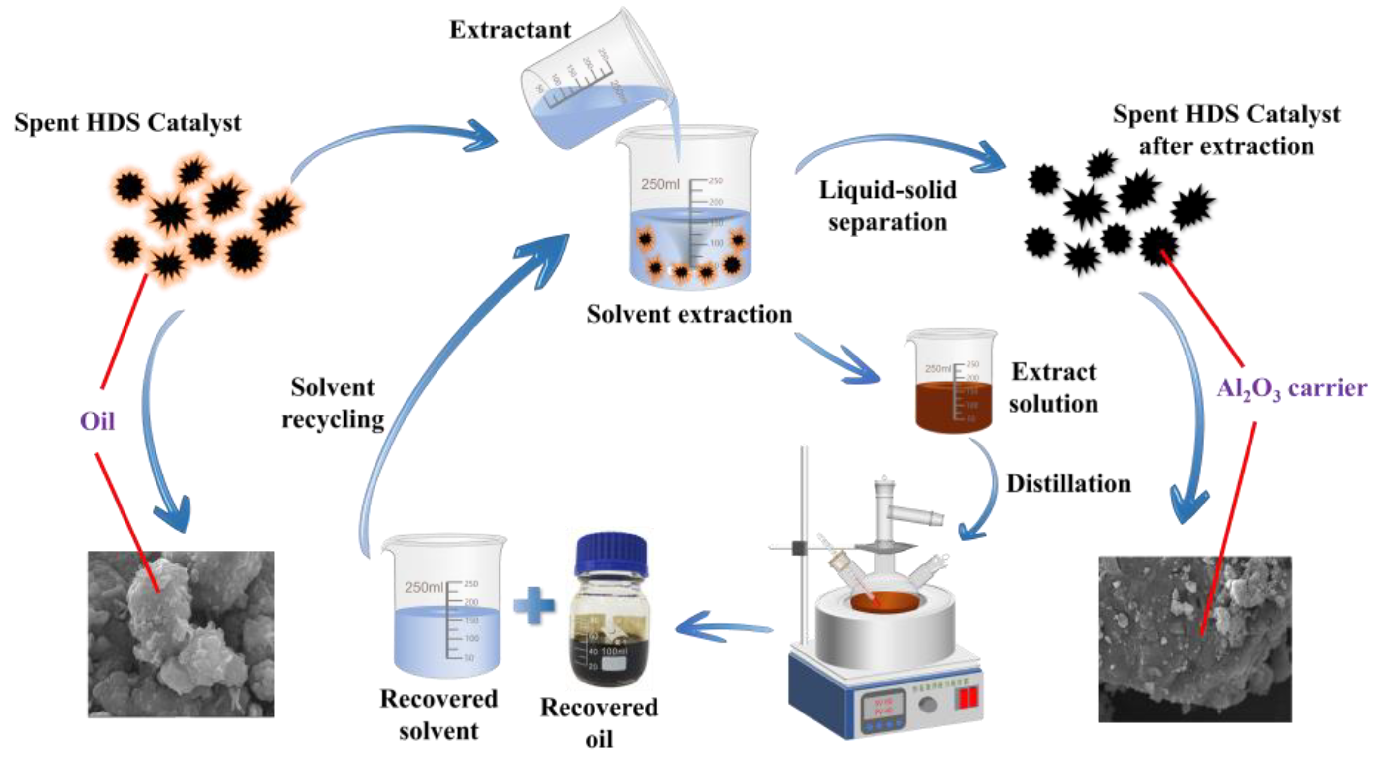
Figure 2.
Chemical thermal washing process flow diagram.
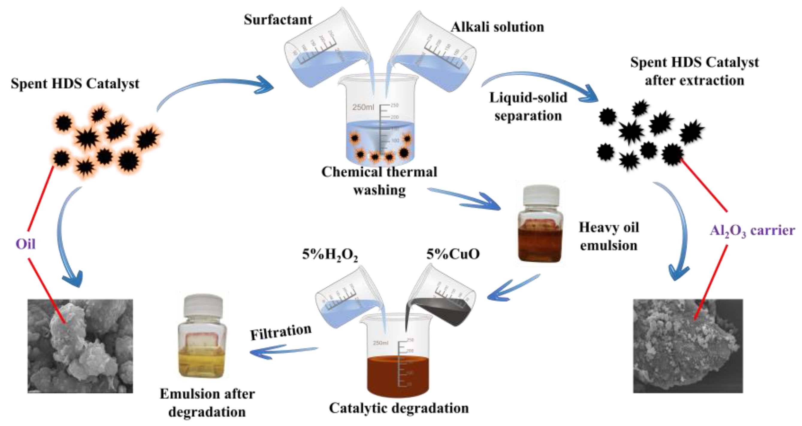
Figure 3.
Pyrolysis Reaction Setup Diagram.
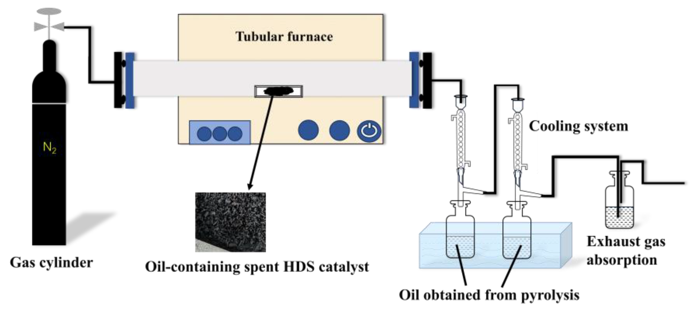
Figure 4.
Efficiency of solvent cleaning of crude oil from spent HDS catalysts.
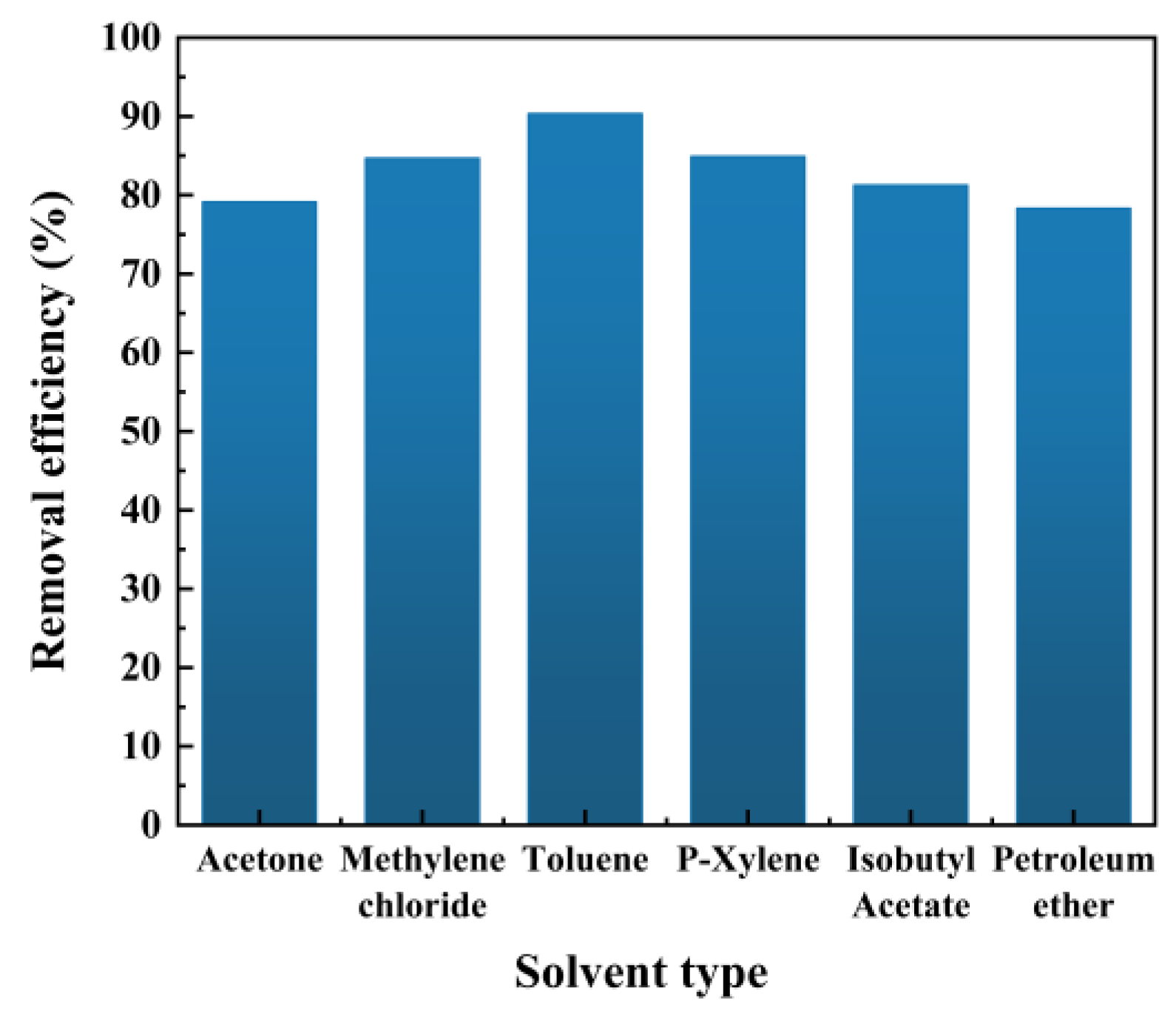
Figure 5.
Effect of (a) liquid-solid ratio, (b) temperature, (c) time, (d) stirring speed and (e) particle size of spent catalyst on oil removal efficiency.
Figure 5.
Effect of (a) liquid-solid ratio, (b) temperature, (c) time, (d) stirring speed and (e) particle size of spent catalyst on oil removal efficiency.
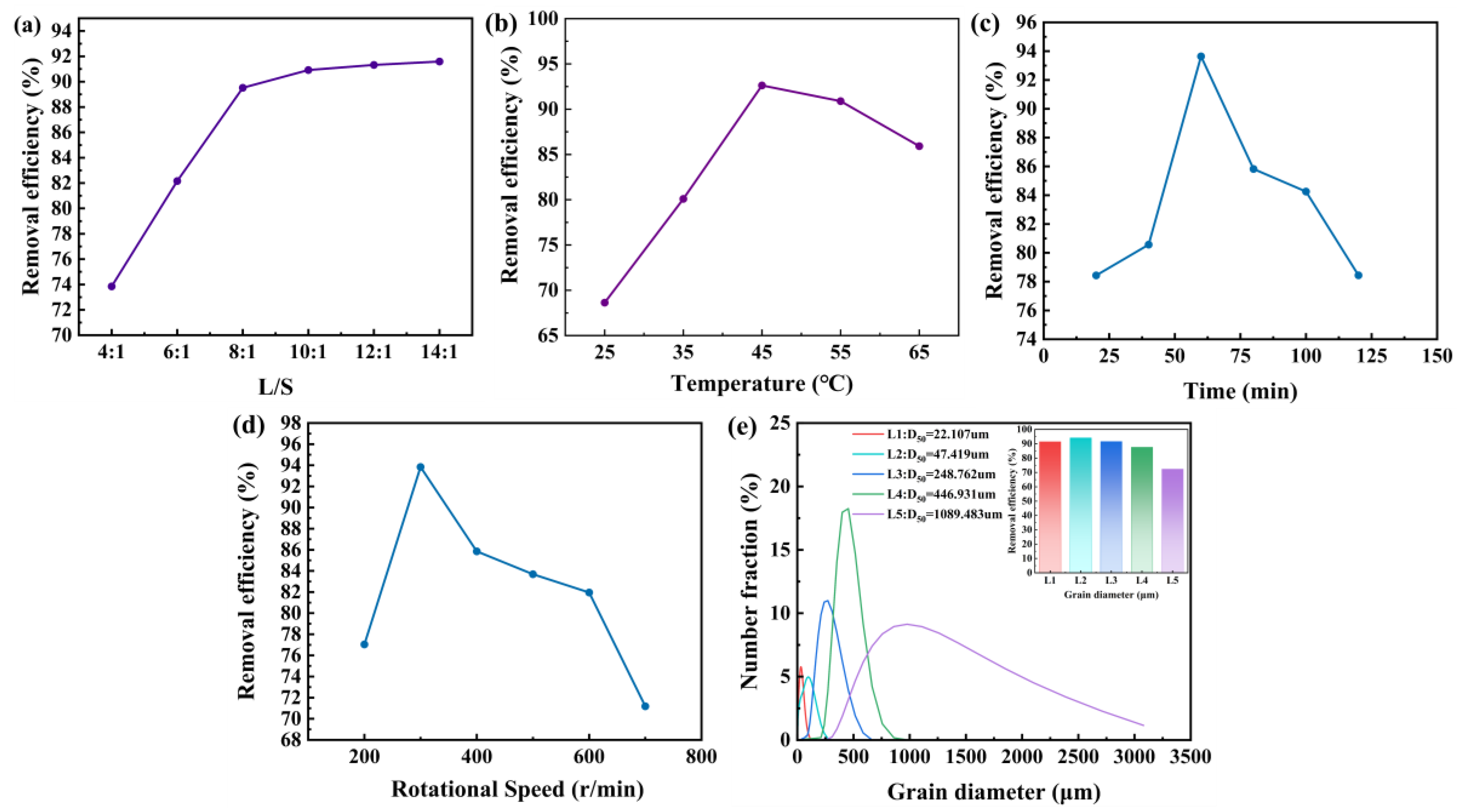
Figure 6.
(a) Diagram of the device for separating and recovering solvent and oil from the extraction solution and (b) extraction efficiency for different cycles and solvent recovery efficiency for each cycle.
Figure 6.
(a) Diagram of the device for separating and recovering solvent and oil from the extraction solution and (b) extraction efficiency for different cycles and solvent recovery efficiency for each cycle.
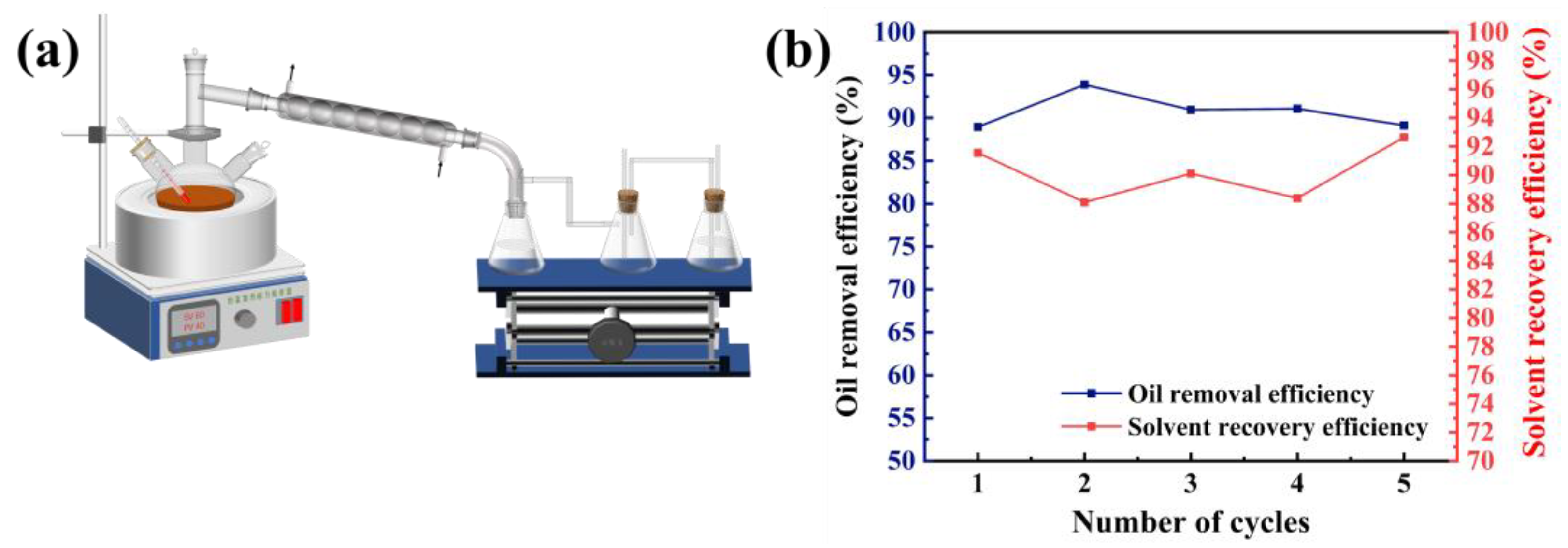
Figure 7.
(a) Diagram of the device for separating and recovering solvent and oil from the extraction solution and (b) extraction efficiency for different cycles and solvent recovery efficiency for each cycle.
Figure 7.
(a) Diagram of the device for separating and recovering solvent and oil from the extraction solution and (b) extraction efficiency for different cycles and solvent recovery efficiency for each cycle.
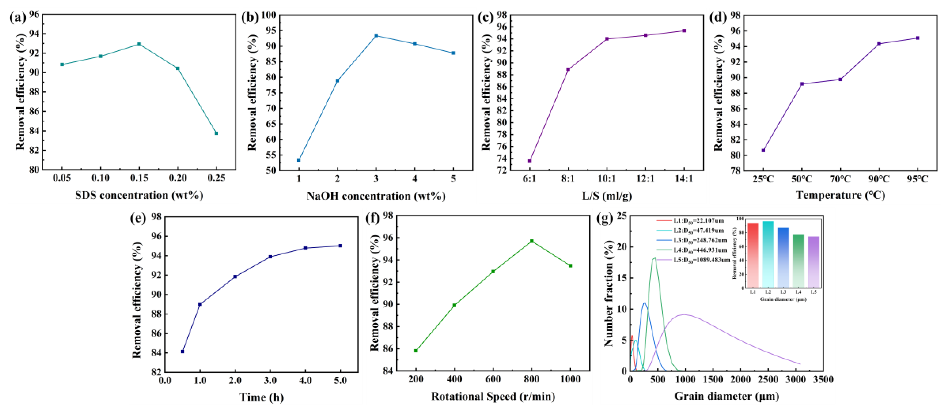
Figure 8.
Infrared spectra of crude oil emulsion before and after degradation.
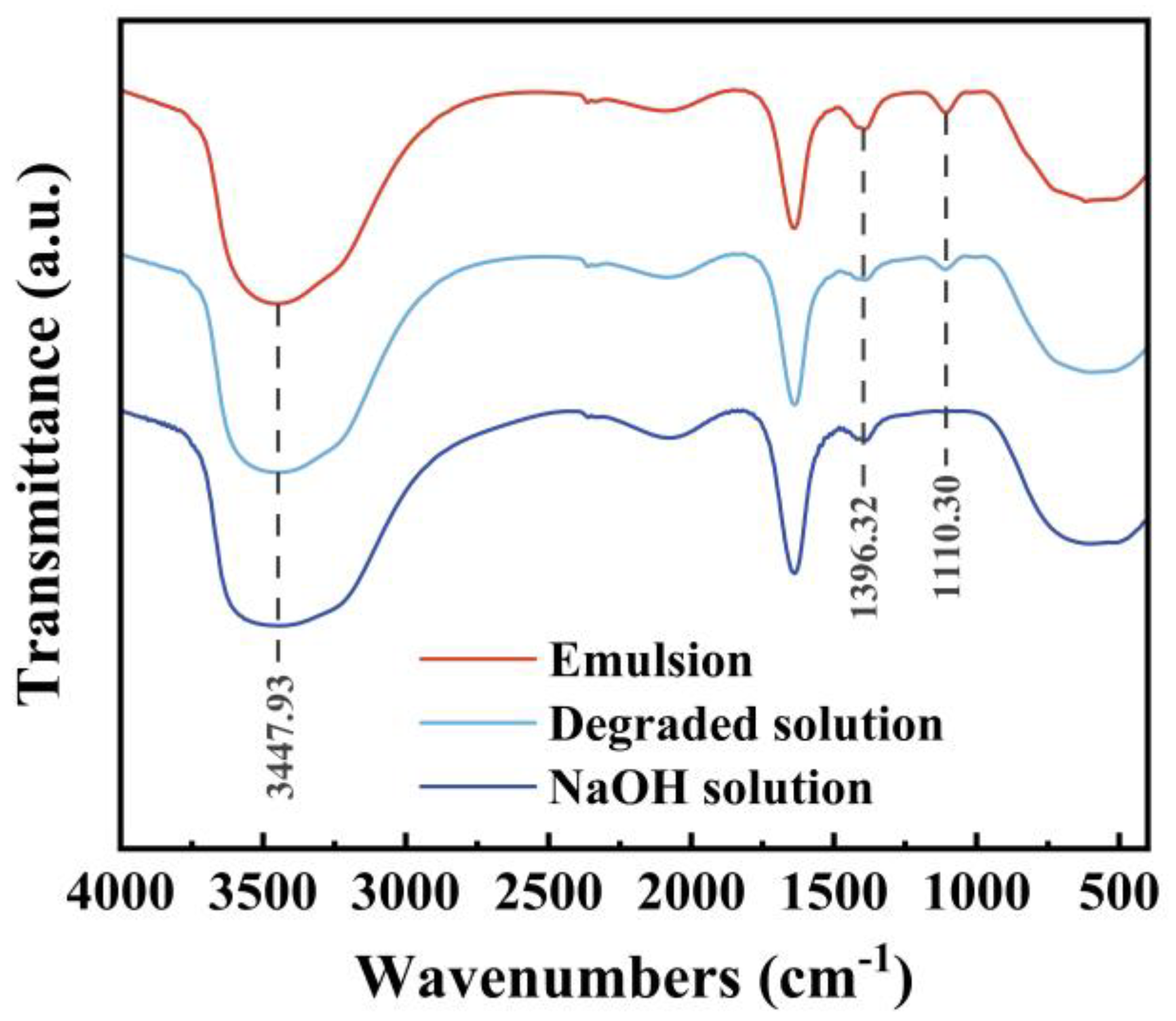
Figure 9.
Effect of (a) temperature and (b) time on thermal degreasing efficiency.
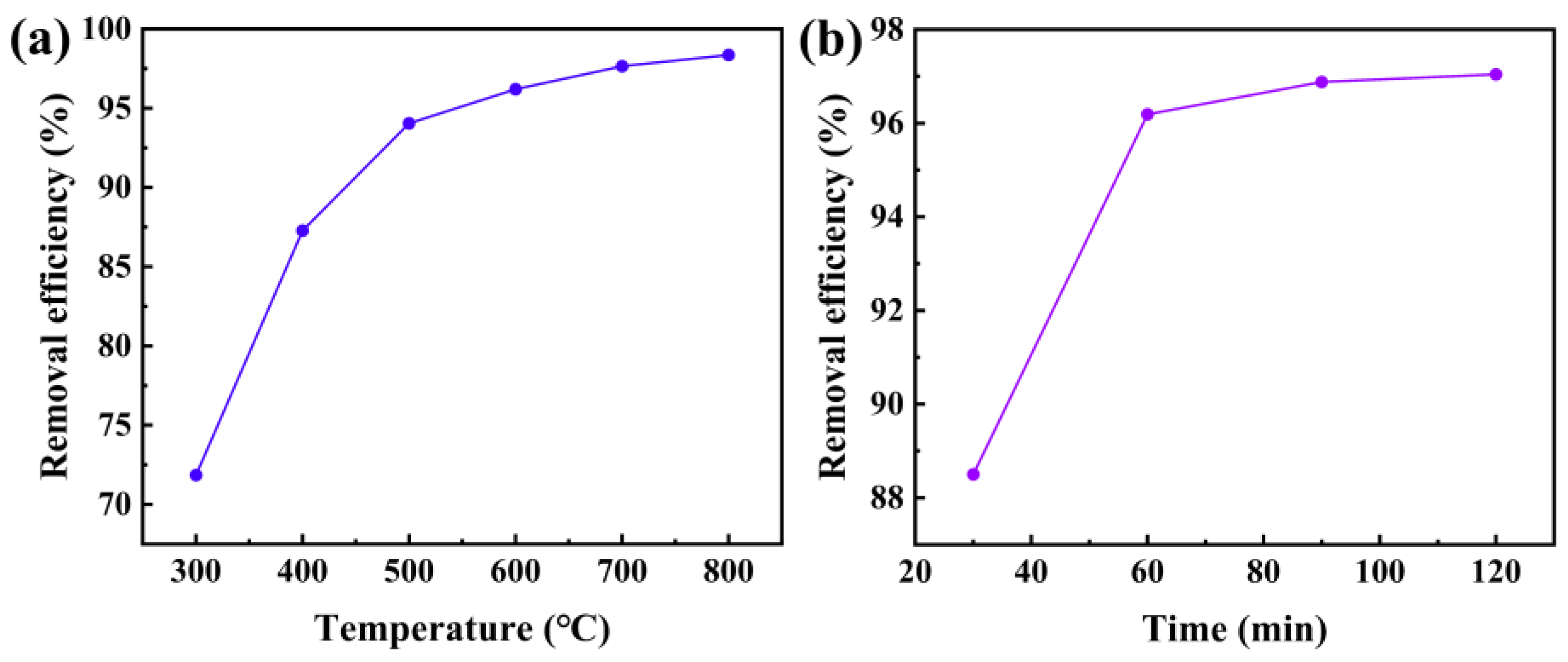
Figure 10.
SEM images of the spent HDS catalyst before treatment (a) and the spent HDS catalysts treated with extraction (b), chemical thermal washing (c), and pyrolysis (d) at different multiplicities.
Figure 10.
SEM images of the spent HDS catalyst before treatment (a) and the spent HDS catalysts treated with extraction (b), chemical thermal washing (c), and pyrolysis (d) at different multiplicities.
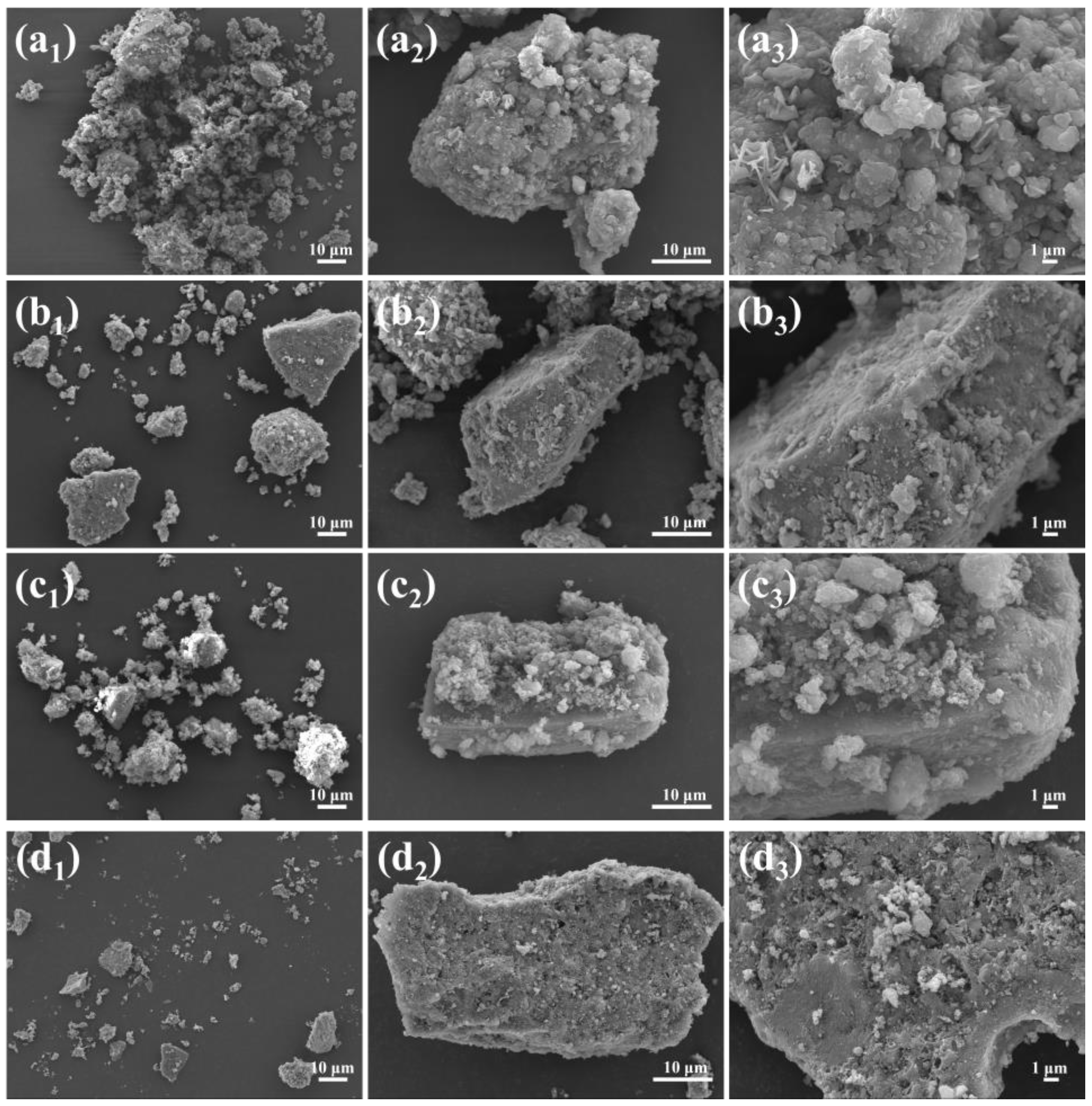
Figure 11.
EDS images of the spent HDS catalysts before treatment (a) and the spent HDS catalysts treated by extraction (b), chemical thermal washing (c), and pyrolysis (d).
Figure 11.
EDS images of the spent HDS catalysts before treatment (a) and the spent HDS catalysts treated by extraction (b), chemical thermal washing (c), and pyrolysis (d).
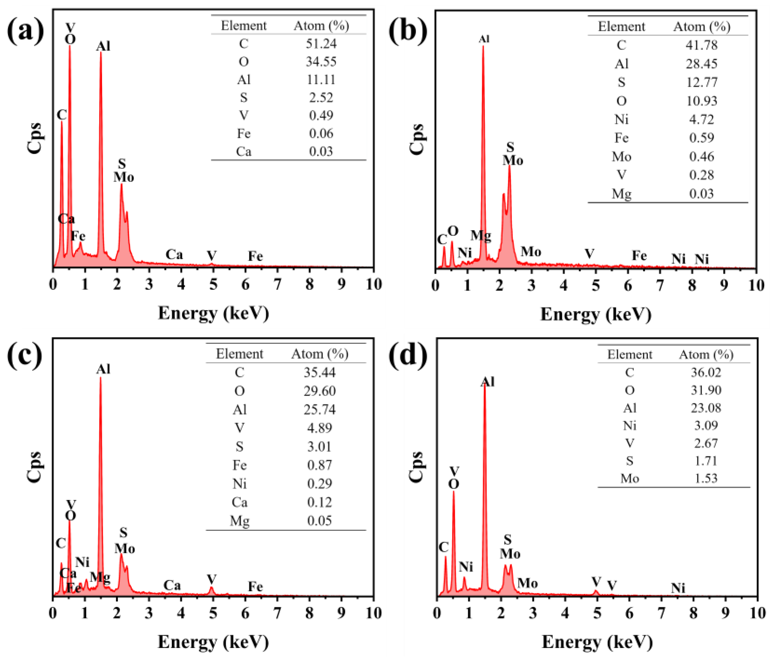
Figure 12.
FT-IR spectra of spent HDS catalyst (a) and spent HDS catalyst treated by extraction (b), chemical thermal washing (c), and pyrolysis (d), respectively.
Figure 12.
FT-IR spectra of spent HDS catalyst (a) and spent HDS catalyst treated by extraction (b), chemical thermal washing (c), and pyrolysis (d), respectively.
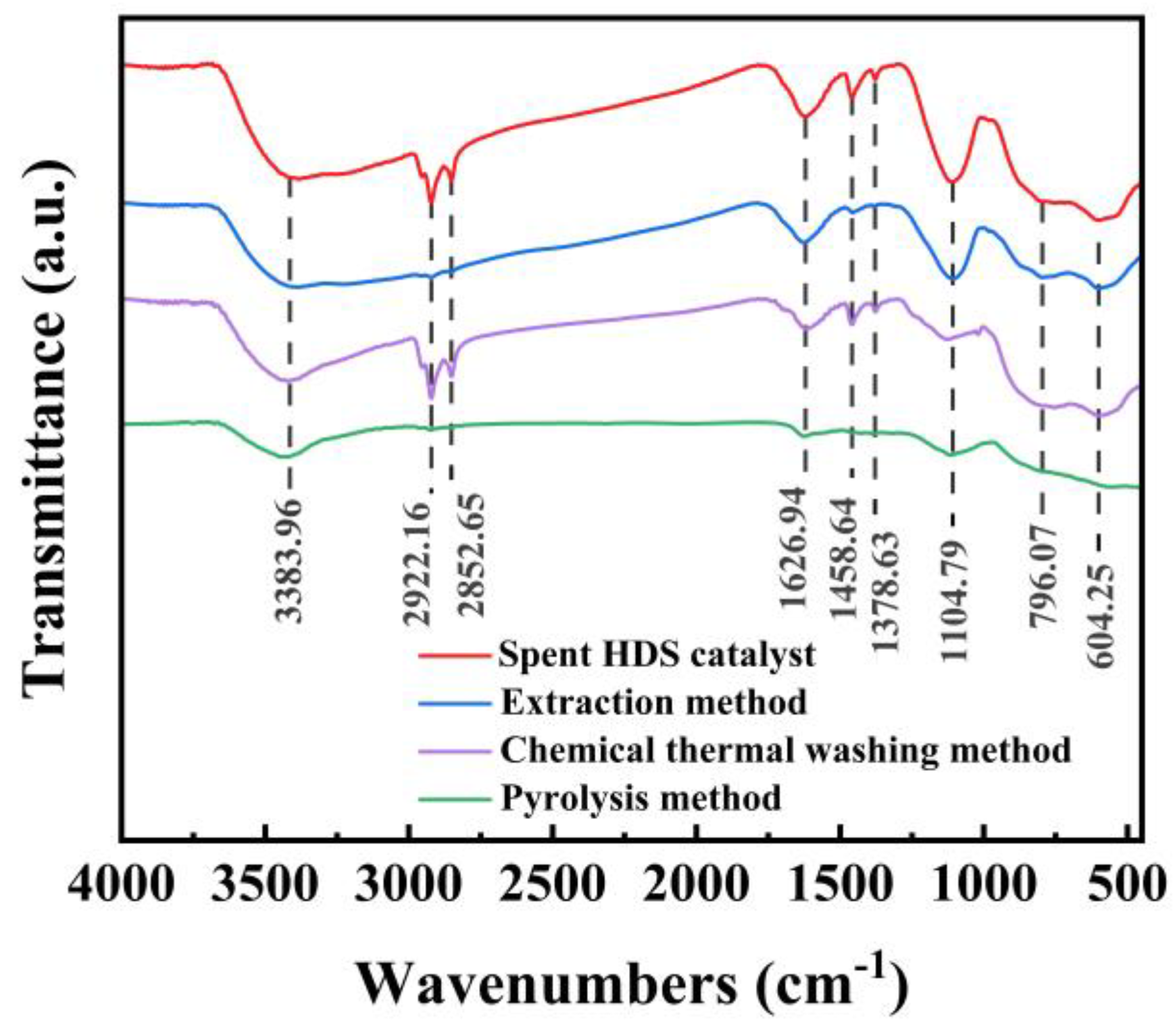

Table 1.
Solvent polarity and boiling point [15].
Table 1.
Solvent polarity and boiling point [15].
| Solvent | Polarity | Boiling point (℃) |
|---|---|---|
| Petroleum ether | 0.01 | 30-60 |
| Toluene | 2.4 | 110.6 |
| P-Xylene | 2.5 | 138.4 |
| Methylene chloride | 3.4 | 39.8 |
| Acetone | 5.4 | 58.08 |
| Isobutyl Acetate | - | 116 |
Disclaimer/Publisher’s Note: The statements, opinions and data contained in all publications are solely those of the individual author(s) and contributor(s) and not of MDPI and/or the editor(s). MDPI and/or the editor(s) disclaim responsibility for any injury to people or property resulting from any ideas, methods, instructions or products referred to in the content. |
© 2024 by the authors. Licensee MDPI, Basel, Switzerland. This article is an open access article distributed under the terms and conditions of the Creative Commons Attribution (CC BY) license (http://creativecommons.org/licenses/by/4.0/).
Copyright: This open access article is published under a Creative Commons CC BY 4.0 license, which permit the free download, distribution, and reuse, provided that the author and preprint are cited in any reuse.


