
Submitted:
19 December 2024
Posted:
20 December 2024
You are already at the latest version
Abstract
We describe three partly-coupled integrated nuclear energy systems enabling base-load nuclear reactors to provide fully dispatchable electricity without greenhouse-gas emissions—replacing gas turbines burning natural gas and batteries storing electricity. First, electricity-to-high-temperature (1800˚C) gigawatt-hour firebrick heat storage converts low-price electricity to high-temperature stored heat to provide dispatchable heat for industry and power generation. Second, Nuclear Air-Brayton Combined Cycles (NACC) with thermodynamic toping cycles using high-temperature stored heat or combustible fuel provide dispatchable electricity. Peak power output can be 2 to 5 times base-load electricity production. The heat-to-electricity efficiency of the thermodynamic topping cycles exceeds 70%. Third, nuclear hydrogen production for industrial markets enables production of dispatchable electricity where hydrogen is used for energy storage but not for the production of heat and electricity. Base-load nuclear reactors send electricity to the grid and/or electrolyzers for hydrogen production depending upon electricity prices. Low-cost hydrogen storage enables meeting steady-state industrial hydrogen demand while hydrogen and grid electricity production are varied. Hydrogen production for industrial uses (ammonia fertilizer, direct reduction of iron ore to iron replacing coke, cellulosic liquid hydrocarbon biofuels replacing crude oil) may exceed 20% of total energy demand. Consequently, this option may become a major source of dispatchable electricity.
Keywords:
Nuclear Power
; Dispatchable Electricity
; Firebrick Heat Storage
; Hydrogen
; Hybrid Energy Systems
1. Introduction
Historically the economic production of electricity has involved a mixture of electricity generation technologies. Base-load electricity was provided by high-capital-cost low-operating-cost technologies such as nuclear reactors. Dispatchable electricity was provided by low-capital-cost high-operating-cost technologies such as gas turbines burning natural gas. The goal to minimize greenhouse gas emissions limits the use of low-capital-cost high-operating-cost technologies such as gas turbines burning fossil fuels. The question is what replaces the historic role of the gas turbine for economic dispatchable electricity? It is a systems problem that requires coupling of different technologies. A set of options to accomplish that task is described herein.
The challenge is complicated by the addition of wind and solar. These technologies can provide low-cost electricity but are not dispatchable. There is no electricity output at times of low solar or wind conditions. These technologies are fuel-saving technologies [1] that makes the economic generating system in much of the United States a system built upon gas turbines where wind and solar reduce natural gas consumption. However, very large scale use of non-dispatchable wind and solar to reduce greenhouse gas emissions increases average delivered cost of electricity to the final customer because of the need to provide low-carbon dispatchable electricity at times of low wind or solar output. This is seen in models [1] and more recently in the increased total cost of electricity in countries such as Germany and states such as California [2]. California has the second highest electricity rates in the United States after Hawaii. Part of these increased costs are associated with early closing of nuclear power plants that eliminated firm low-carbon dispatchable electricity to the grid.
Wind and solar deployment results in large variations of electricity demand from dispatchable electricity sources and large changes in wholesale electricity prices with time. One example is the average net load of electricity in California over a period of one day as shown in Figure 1 [3] after subtracting wind and solar output. Figure 2 shows the wholesale price of electricity over one year in California [4,5]. At times of high wind and solar input, the wholesale electricity prices are zero or negative. Negative wholesale prices occur because of (1) many subsidies for wind and solar production are based on output independent of whether there is a demand and (2) continued operation of nuclear and fossil plants at these times so they are able to provide electricity when needed. Many plants cannot quickly startup or shut down. Models [1] and experience show that some wind and solar can lower costs on a small scale but very large-scale deployment will more than double costs to the consumer. That is because consumer electricity cost [6,7,8] include (1) wholesale electricity cost, (2) cost of whatever systems provide dispatchable electricity on an hourly to yearly basis and (3) transmission and distribution costs.
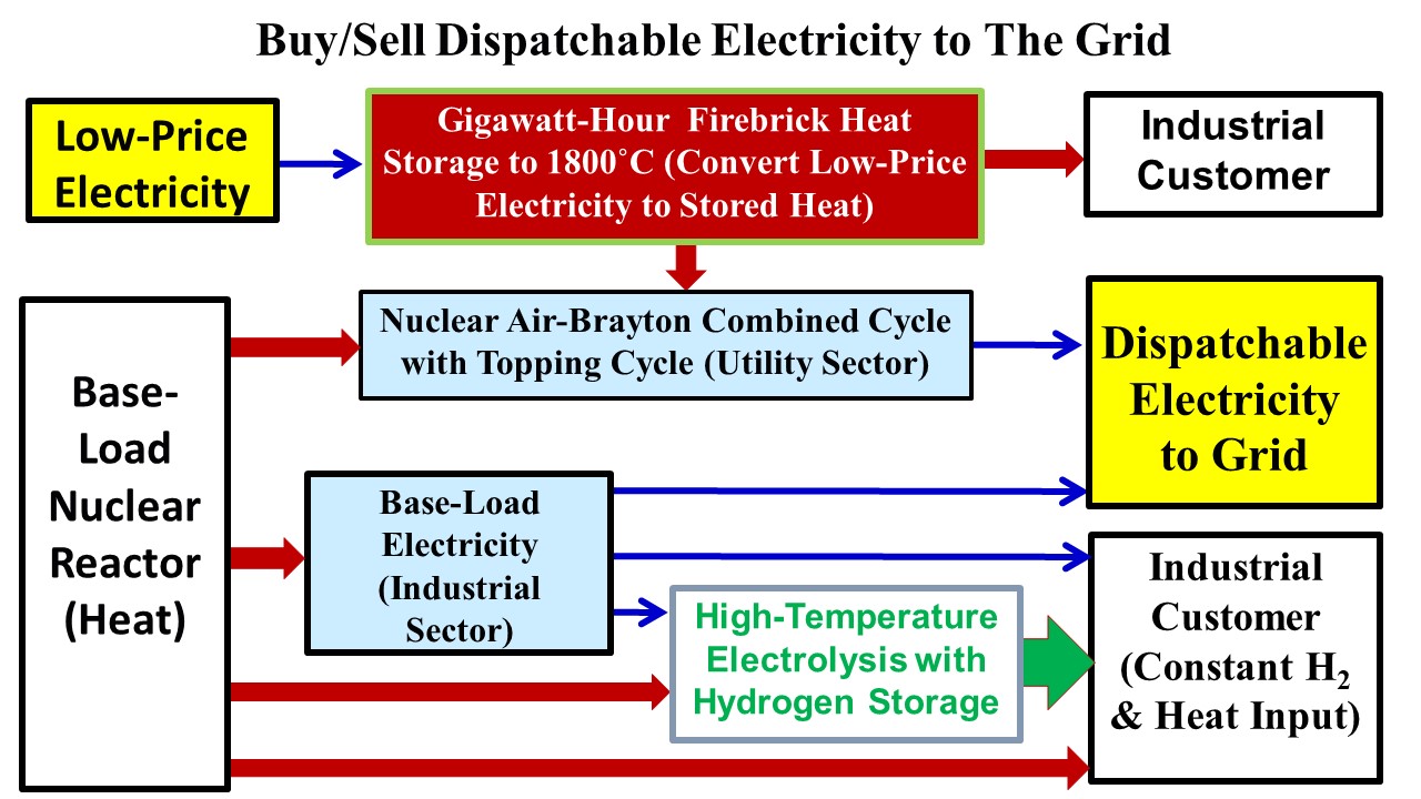
Replacement technologies are required for the gas turbine to provide low-cost dispatchable electricity and use low-price electricity when available from wind and solar. We describe three coupled technologies (Figure 3) that together can achieve that goal. High-temperature heat storage and hydrogen storage are the low-cost storage media that enable base-load reactors with dispatchable electricity.
The first technology is Gigawatt hour Firebrick Energy Storage (GIFES) that converts excess low-price electricity into large-scale high-temperature stored heat for industry or electricity generation. The second technology is the Nuclear Air-Brayton Combined Cycle (NACC) with a thermodynamic toping cycle that when coupled to GIFES enables a base-load reactor with NACC to buy and sell electricity. Combining the technologies functionally replaces (1) gas turbines burning natural gas and (2) electricity storage technologies such as batteries. Third, Nuclear Industrial Stored-Hydrogen Heat and Electricity (NISHHE) systems provide dispatchable electricity using hydrogen for energy storage but not for electricity generation. Base-load reactors produce variable electricity for the grid and hydrogen for industry. Hydrogen storage assures steady-state delivery to industry with variable hydrogen production. Because hydrogen production for industrial purposes could become 20% of total energy consumption, this option may become the largest source of dispatchable electricity. The industrial sector provides hydrocarbon cellulosic biofuels and hydrogen that can be used to address seasonal variations in energy demand. The technological readiness levels (TRL) of these technologies vary from 4 to 8 where a TRL of 9 indicates a commercially deployed technology.
2. Converting Low-Price Electricity to Large-Scale High-Temperature Stored Heat
Methods to beneficially use excess low-price electricity can increase revenue for the electricity grid. This can be done by conversion of excess low-price electricity into high-temperature stored heat in firebrick. The capital costs are low and the heat output is in the form of a hot gas. Most uses of fossil fuels involve burning the fuel in air to produce a hot gas in a boiler or furnace. If the heat storage technology produces a hot gas, it is a drop-in replacement for burning fossil fuels. If the heat storage system is depleted, one can burn fossil fuels, biofuels or hydrogen to provide a continuous supply of hot gas to the customer. However, one needs storage capacities in excess of a 100 hours or more [9] to minimize the use of backup combustible fuels to (1) avoid major impacts of multiday low solar or wind conditions and (2) take full advantage of excess low-price electricity on weekends due to lower weekend electricity demand. Firebrick heat storage is also the enabling technology for base-load reactors with NACC that can buy or sell electricity replacing the roles of gas turbine and electric storage battery. Firebrick heat storage will likely set the minimum wholesale price of electricity to near that of the competing sources of heat for industry. The potential market is very large [10]
There are three generations of firebrick heat storage systems. For more than 50 years low-technology firebrick systems have been used in home and commercial facilities for general heating [11]. These systems contain cheap firebrick and low-cost electrical heaters similar to those in electric ovens to heat the firebrick. The firebrick is heated at times of low-price electricity. Cold air is blown through the firebrick with channels producing hot air for space heating or production of low-temperature steam as needed. These systems are found in countries where the electricity rate structure varies the price of electricity to the customer with time.
The second-generation systems, being developed by Rondo [12,13] and others, are higher-temperature firebrick systems to provide heat at higher temperatures to industrial customers. These use higher-temperature off-the-shelf resistance heaters with peak temperatures to 1100˚C. These systems are beginning to be commercially deployed.
The third-generation systems involve new technologies and enable peak temperatures to 1800˚C—the combustion temperature of natural gas. As such, these firebrick heat storage systems can replace fossil fuels in industrial applications including gas turbines. They are enabled by two new sets of technologies. The first technology is the invention of electrically-conductive firebrick by Forsberg (author) and Stack [14] and is being commercialized by Electrified Thermal Solutions [15]. Earlier studies [16] had explored general uses for large-scale heat storage using firebrick. Normal firebrick that has been used for thousands of years and is an electrical insulator. By doping the firebrick with materials such as nickel oxide, it can be made electrically conductive and used as a resistance heater at very high temperatures. This enables embedding electrically conductive firebrick as the heating element in large volumes of traditional very-low-cost firebrick. Because it is bulk heating of firebrick, it is more robust than traditional electric resistance heating. A system schematic is shown in Figure 4. It is in the demonstration stage of commercialization
Electrically-conductive firebrick is conductive through the bulk of the brick and between bricks. This is in contrast to typical electrical resistance heaters made of SiC and MoSi2 that form an insulating layer on their surfaces. If these heaters break anywhere, there is no electrical flow. Electrically conductive firebrick heaters are made of multiple layers of overlapping brick with high redundancy (multiple flow paths through different bricks), Heater circuits can be many tens of meters long versus typical resistance heater rods with lengths of one or two meters. Conventional firebrick provides the electrical insulation and most of the heat storage capacity. These characteristics enable (1) internal heating of very large volumes of firebrick and (2) high voltage and power inputs with low capital costs relative to traditional electric heater systems that operate at lower voltages with individual heaters with much lower power outputs.
The second recent development [17] is the Gigawatt-Hour Firebrick Energy Storage (GIFES) system, a firebrick storage system to enable long-term heat storage for hours to months at very high temperatures at the multi-gigawatt-hour scale. This technology is significantly behind that of electrically conductive firebrick with an estimated TRL of 4. There are two distinctive characteristics of these storage systems.
- Firebrick costs. The cost of firebrick per unit of heat storage tends to go down as the peak allowable storage temperature goes up. A temperature swing of 1000˚C from hot-to-cold is five times a temperature swing of 200˚C in a low-temperature firebrick system and implies five times as much heat storage per ton of firebrick.
- Insulation costs. Very high-temperature low-cost storage is only viable on a large scale because of the cost of the insulation system. Heat storage increases as the cube of the storage system size. The insulation system increases as the surface area which increases as the square of the system dimensions. Increasing the firebrick heat storage dimensions from 1 meter to 10 meters increases heat storage capacity by a factor of 1000. A 10-meter cube has storage capacity on the order of a gigawatt hour. The surface area increases by a factor of 100 reducing insulation costs per unit of heat by a factor of ten. Based on economic tradeoffs, traditional large-scale firebrick heat storage systems today have heat losses between 1 and 3%. The only way to obtain a low-cost high-temperature heat storage system is make it large so the cost of the expensive insulation system goes down per unit of heat storage. That favors gigawatt-hour systems.
Large-scale high-temperature heat storage for short periods of time has been used for centuries in the glass and steel industries. For example, in an industrial natural-gas-fired glass furnace (1) incoming air is heated in a firebrick recuperator, (2) hot air exiting from firebrick recuperator is further heated by natural gas, (3) hot gas flows over the top of the melting glass formers and (4) hot gas heats the glass components by radiative heating into molten glass. Peak gas temperatures are near 1550˚C. The somewhat cooler exit gas (1300 to 1400˚C) goes through a second large brick recuperator heating the firebrick before exiting to the stack. When this second firebrick recuperator is fully heated, gas flow directions are reversed. Cold air enters the second recuperator, is heated (1200 to 1300˚C), natural gas further heats the hot gas, the hot gas flows over the glass surface heating the glass formers and then exits through the first recuperator while heating it with the exhaust gas exiting to the stack. This saves massive amounts of energy. Cycle times are measured in hours.
Calculations and experience show that when there is no gas flow, very high-temperature heat relatively quickly goes from the hot parts of recuperators to the cold parts of recuperators. There are two heat transfer mechanisms: (1) heat conduction through the fire brick and (2) radiation heat transfer that increases by the fourth power of the absolute temperature. Because there was no industrial need for long-term high-temperature heat storage, methods to enable long-term heat storage were not developed.
We are developing [17] a method for long-term high-temperature heat storage as shown in Figure 5 and Figure 6. In Figure 5 it is assumed some fraction of the firebrick is electrically conductive firebrick that acts as electric resistance heaters to heat the bulk of the firebrick. With this option, the rate of heating firebrick is independent of other design features and very large electrical inputs are possible. In Figure 6 cold air is heated external to the firebrick storage system and the resultant hot air is blown through the firebrick to heat it from top to bottom—similar to recuperators in the glass and steel industry. The maximum rate of heating is limited by gas flow rates.
The storage system is built of firebrick surrounded by firebrick insulation that is within a metallic shell to provide a gas-tight system. In a normal firebrick recuperator in the glass or steel industry, the interior is filled with firebrick with gas-flow channels from the bottom to top of the storage system. If the top of the firebrick recuperator is hot and the bottom is cold, heat moves from the hot zone to the cold zone by conduction through the brick and radiative heat transfer from surface to surface.
To provide long-term heat storage where there is hot and cold firebrick in the same system, vertical heat transfer must be minimized. This is done by using two types of firebrick in horizontal layers like a layer cake. The first set of horizontal layers are solid firebrick that prevents gas flow through the layer and have a low thermal conductivity—insulating firebrick [18]. The second set of horizontal layers is the firebrick used for most of the heat storage with holes or channels that enables horizontal gas flow. Heat storage firebrick [19] has a much higher density to maximize heat storage per unit volume and higher thermal conductivity to transfer heat from flowing gas to the interior of the firebrick. Firebrick with vertical flow channels connect the layers of heat-storage firebrick with horizontal flow channels at the opposite ends of the storage system. Alternatively, vertical flow channels for gas flow between the horizontal layers can alternate between the center of the firebrick system and the exterior. Horizontal firebrick with flow channels is chosen to maximize heat capacity (stored heat) per unit volume. This layer may also include electrically conductive firebrick for heating of the firebrick.
This geometry slows heat transfer from the hot firebrick on top to the cold firebrick at the bottom. With hot firebrick on top of cold firebrick, there is no convective gas flow to transfer heat from hot firebrick to cold firebrick. Hot gas is less dense than cold gas. There is slow conductive heat transfer through the insulating firebrick in the downward direction. The thermal conductivity of insulative firebrick (~0.4 W/m-K) is more than an order of magnitude less than firebrick used to store heat [18,19]. Heat conduction through the higher-thermal-conductivity heat storage firebrick from top to bottom is slowed by the long S-shaped conduction pathway where most heat transfer is in the horizontal direction. Similarly, radiation heat transfer is slowed by the torturous path from top to bottom of the heat storage system. The firebrick heat storage system may be 20 to 30 meters tall; but, the gas flow path and heat storage firebrick path may be 100s of meters long.
The density of insulative firebrick and thus the volumetric heat capacity is a fourth or less of firebrick used for heat storage. If one considers a system where by volume 20% is insulative firebrick, 10% gas flow channels and 70% heat-storage firebrick, the insulative firebrick will be less than 10% of the heat storage capacity.
If there is no gas flow, over time the interface zone between hot and cold zones will grow. However, whenever cold gas enters the bottom and is heated, it is initially heated by the warm firebrick and then the hot firebrick. In the process, the hot-to-cold interface zone shrinks. Because of this feature, occasional operation greatly reduces heat loses and keeps the hot zone hot. The actual design depends strongly on goals—length of storage time and how the heat storage system will be operated. For example, if providing industrial heat such as for a glass furnace, at times of low electricity prices electric heating will (1) provide heat for immediate use and (2) heat for storage when electricity prices increase. The system is operating in a charging and discharging mode at the same time. For a power cycle as described below, the system will either be in charging or discharging mode—but not both.
Low-cost high-temperature storage is enabled by very large systems that are 10s of meters tall with multiple horizontal layers of solid low-conductivity firebrick that limits heat transfer in the vertical direction. Large systems minimize the total external surface area per unit of heat stored and thus heat loses through external insulation. Conductive firebrick resistance heaters can be designed for high voltages that minimizes the cost of supporting electrical systems in large systems. All of the auxiliary system costs decrease per unit of stored heat. The incremental capital cost for storing heat is estimated to about $ 10/ kWh [16,20]—far below competing technologies. GIFES storage is at a TRL level of four. The component technologies are commercial. It has the potential to absorb all low-price electricity that is below the cost of heat.
3. Nuclear Air Brayton Combined Cycles with Thermodynamic Topping Cycles
Low-cost high-temperature heat storage is an enabling technology for base-load nuclear reactors that buy and sell electricity to the grid as needed. The enabling power cycle is the Nuclear Air-Brayton Combined Cycle with thermodynamic topping cycle that can use stored high-temperature heat as described earlier with stored heat-to-electricity efficiencies exceeding 70%.
Gas Turbine Combined Cycle (GTCC) power plants have become the favored technology to produce dispatchable electricity to the grid because of their low capital cost and high efficiency. Historically the preferred fuels have been natural gas and oil; but, GTCC can burn almost any combustible gas including hydrogen and biofuels or use stored heat. The technical advances in gas turbines enable NACC power cycles [21,22,23,24,25,26] with thermodynamic topping cycles and integrated heat storage. NACC can couple to a sodium, salt, helium or other high-temperature reactors or Concentrated Solar Power (CSP) systems. Light water reactor temperatures are too low to couple to these power cycles. While research on NACC is relatively new, these power cycles are based on existing technologies.
Figure 7 shows a specific design [22] of NACC. There are many variants. The reactor operates at base load. External air filtered, compressed, heated in heat exchanger 1 (HX1), goes through turbine 1, is reheated in HX2, goes through turbine 2, is reheated in HX3, goes through turbine 3 and exits to the steam bottoming cycle. The warm air from the Brayton cycle goes through the heat recovery steam generator (HRSG) and up the stack. Steam produced in the HRSG can be used to produce electricity or sent to industry. In base-load operation, this system is similar to a GTCC except it uses nuclear heat. In this context, using nuclear heat to drive a gas turbine is not new concept [27]. In the 1950s and early 1960s the U.S. began development of a nuclear-powered jet bomber with unlimited range. The reactor provided the heat that was transferred to the jet engines using sodium coolant. There was a major development program to develop the sodium-to-air heat exchangers for the jet engine. What has happened since then are a set of extraordinary advances in gas turbine technology.
For peak electricity production, the hot air exiting HX3 can be further heated by going through electrically-heated firebrick as described earlier or by adding a combustible fuel before entering Turbine 3 to produce peak power—a thermodynamic peaking cycle. The peak temperature limits of modern turbines are far beyond power reactor temperatures. Table 1 shows the nominal projected performance of this system for different reactor heat input temperatures and different peak gas-turbine temperatures assuming existing gas turbine technology. Only the last turbine can be used for peaking power because if you add incremental heat before Turbine 1 or Turbine 2, the gas temperatures exiting these turbines into Exchangers 1 and 2 would be above the reactor coolant temperatures.
The incremental heat-to-electricity efficiencies for the added high-temperature heat are between 71 and 75%, far above the natural gas-to-electricity efficiency of existing GTCC systems and a higher incremental heat-to-electricity efficiency than any other heat engine. This has several implications.
- Replacing battery storage. The electricity-to-heat conversion efficiency is above 95%. The daily spread in California wholesale electricity prices (Figure 2) is such that a system will operate many days of the year by buying electricity at times of low prices and selling at times of higher prices—reducing the number of hours per year with very high wholesale prices.
- Combustible fuels. Peak power can be obtained using combustible fuels. The very high efficiency implies much lower fuel costs.
The four cases that are shown in Table 1 include two cases for sodium-cooled reactors and two cases for salt-cooled reactor or CSP systems. Two peak turbine temperatures are shown for each NACC design. The first is for uncooled turbine blades. The second is for cooled turbine blades used in existing high-performance GTCC systems. With advances in gas turbines, peak allowable temperatures are expected to increase with increasing efficiency. Higher performance turbine blades are typically developed for military jet engines with the technology later transferred to commercial aircraft engines and then to GTCC plants. The overall NACC plant efficiencies when producing peak power with internally-cooled turbine blades are near 60% and similar to current GTCCs.
The other characteristic of NACC is that the topping cycle dramatically increases peak electricity output. For the first case in Table 1, if the base-load power output is 1 megawatt, operating the peaking cycle increases the Brayton cycle output by 46.4% (relative factor of 1.464) and the total plant output increases by 152.2%. If cooled turbine blades are used with higher-temperature heat input, the total plant output increase by a factor of five. Furthermore, the incremental capital cost for this peaking capacity is low, similar to a CCGT. The peak input temperatures are easily met by firebrick heat storage systems.
Thermodynamic topping cycles are not new. The Indian Point I nuclear power plant in the United States was a pressurized water reactor that produced saturated steam that was then superheated with an oil-fired superheat before the steam went to the steam turbine. When that plant was built, it had the highest incremental heat-to-electricity efficiency of any oil-fired system.
The incremental capital cost for this peak power producing capability is low—oversizing the last gas turbine and the HRSG and its steam turbine with associated electric generators. The incremental cost of adding a thermodynamic topping cycle to NACC will be less than the cost per kilowatt of capacity of a fossil-fuel gas turbine or GTCC. These thermodynamic topping cycles have the remarkable feature of the lowest incremental capital costs per unit of added assured electric generating capacity and the highest efficiency of any method to convert heat to electricity. This creates the powerful economic incentives for development of NACC. The other observation is that if using firebrick heat storage, the scale of heat storage is measured in gigawatt hours. For example, if use a modular reactor with an output of 100 MWe and a peak power output of 300 MWe, the heat input for that additional 200 MWe (assuming 70% heat-to-electricity efficiency) is 285 MWt. Several hours of operation require a gigawatt hour of heat storage. The electricity to charge GIFES is from the grid at times of low wholesale electricity prices—including base-load electricity from the reactor with a power station that buys and sells electricity. Utility gas turbines have significant development costs—but the technology is well understood thus low technical risk. The engineering designs are for long lifetimes, not pushing the performance envelope that is characteristic of may military gas turbines.
4. Hydrogen for Electricity Storage
Traditional electricity storage technologies are expensive and involve losses in efficiency. The round-trip efficiency of pumped hydro and batteries for electricity storage in real systems is about 80% because of the multiple energy conversion steps. For batteries it is from AC to DC electricity, reversible chemical reaction, and DC to AC electricity. For pumped hydro its electricity to mechanical work in a pump to move water uphill and then in the reverse direction. Efficient energy storage requires avoiding multiple conversion steps with associated losses, and low capital costs.
Electricity storage may be viable using hydrogen that is produced and consumed in industrial facilities. A simplified schematic of the Nuclear Industrial Stored-Hydrogen Heat and Electricity (NISHHE) system [28,29,30] is shown in Figure 8. The base-load reactor provides heat to produce electricity, heat to the hydrogen production system and heat to the chemical plant. High-Temperature Steam Electrolysis (HTSE) using heat and electricity converts water into steam and electrolyzes that steam to produce hydrogen and oxygen. The hydrogen goes to the chemical plant that may produce ammonia, liquid hydrocarbon fuels, iron or other products. Most chemical uses of hydrogen are exothermal chemical reactions that generate heat including ammonia and hydrocarbon fuel production [31]. Excess heat from the chemical plant is sent to HTSE to reduce nuclear heat input from the reactor. HTSE is receiving heat from two sources. The chemical plant may require steam at different temperatures than required by HTSE; thus, excess lower-temperature steam at one pressure may be sent from the chemical plant to the HTSE unit while the chemical plant receives steam at higher temperatures from the reactor.
Between the HTSE and the chemical plant is hydrogen storage that may be medium pressure hydrogen tanks or underground storage or other low-cost industrial hydrogen storage technology. When not selling electricity to the grid, HTSE operates at full capacity with hydrogen sent to the chemical processes and storage. At times of high-priced electricity, (1) the HTSE system operates at part load with electricity diverted to the electricity grid and (2) hydrogen for the chemical plant comes from storage and part-load operation of the HTSE system. The high-capital-cost nuclear and chemical plants operate at full capacity with dispatchable electricity to the grid and variable operation of HTSE and the hydrogen storage system. HTSE is at the early deployment stage where projected capital costs are expected to drop dramatically. Unlike conventional water electrolysis systems that contain expensive noble-metal catalysts, HTSE does not contain high-priced materials of construction. Hydrogen is the storage mechanism enabling variable electricity with constant hydrogen to the chemical plant. This creates a NISHHE system that provides chemical plant utilities the option for added revenue by selling electricity at times of higher prices. The system has several special characteristics.
- Efficiency. With NISHHE, there are no energy conversion steps and associated energy losses to provide the storage function enabling dispatchable electricity. This is in contrast to batteries and pumped hydro with multiple energy conversion steps. There are some hydrogen compression cost for storage, but they are small energy losses.
- Storage costs. Hydrogen storage in medium-pressure low-cost hydrogen tanks or underground is cheap compared to batteries or stored water behind dams.
- Capital costs for peak electricity production. For NISHHE, it’s the incremental capital cost of base-load nuclear electricity sold at times of peak electricity prices plus some additional HTSE capital costs because the hydrogen plant does not operate at base-load.
The hydrogen is made by high-temperature electrolysis [32,33,34], a process significantly more efficient than conventional water electrolysis. The inputs are heat to convert water to steam and electricity. HTSE is steam electrolysis. The system can be coupled to any reactor including light-water reactors. High-temperature electrolysis is in the early stages of commercial deployment [34].
The largest future market for nuclear energy may be the industrial sector. There is a long history of nuclear power plants that have sold steam to nearby customers [35]. What has changed is that industrial facilities are building nuclear reactors to meet their energy needs. The first such large facility is now under construction in China [36] where two large pressurized water reactors (PWRs) and one high-temperature gas-cooled reactor (HTGR) are being built to primarily produce industrial steam for one large chemical complex. The HTGR is used to boost steam temperatures from the PWRs to provide high-temperature steam for specific chemical processes. Large chemical plants typically require steam at multiple temperatures and pressures. Electricity production is a secondary product. In the United States, Dow Chemical [37] is planning to build four X-Energy high-temperature reactors for its Seadrift site in Texas. As discussed below, the industrial demand for energy may exceed that of the electricity grid.
Within the industrial sector, the production of hydrogen for industrial purposes may ultimately consume 20% of global energy production. That creates the option for low-cost dispatchable electricity on demand but only in those locations near these large industrial facilities. In this context, there are two hydrogen futures. The first future is the use of hydrogen as an energy source such as for fuel cells in vehicles, providing high-temperature heat or heating homes. In these applications there are many alternatives to hydrogen. The size of this hydrogen future is unknown. The second set of hydrogen applications are in industrial processes that require the hydrogen atom—no substitution is allowed. There are at least four such categories that by themselves may result in 20% of all global energy production used to produce hydrogen.
Ammonia (NH3). Ammonia is the primary global fertilizer and its use feeds about half the world. Hydrogen is a component of ammonia and thus required to produce ammonia. Currently most of this hydrogen is made by converting methane to hydrogen and carbon dioxide. One alterative is hydrogen production by HTSE. Estimates are that between 1.5 and 2% of global carbon dioxide emissions are from ammonia production.
Iron and steel. Today we globally mine 2.6 billion tons of iron ore per year and convert it into iron in blast furnaces where the oxygen is removed from the iron oxide by the chemical reaction of carbon from coke producing carbon dioxide. The production of steel from iron ore is responsible for about 8% of global carbon dioxide emissions. The alternative low-carbon process is direct reduction of iron ore (iron oxide) with hydrogen producing sponge iron with the oxygen removed from the iron ore in the form of water. This process is expected to replace the use of coke. Large scale pilot plants are in operation [38].
Cellulosic Hydrocarbon Liquid Fuels (Gasoline, diesel, jet fuel and chemical feed stocks). About half of all energy to the final consumer in the United States is from products of crude oil. There is sufficient cellulosic biomass to replace crude oil products starting with cellulosic biomass and massive external inputs of hydrogen and heat at the bio-refinery. For the United States, the quantities of hydrogen would exceed 100 million tons per year—more than all other hydrogen applications in combination. This option is discussed separately in the next section because (1) of the impacts on dispatchable electricity production and (2) hydrocarbon fuels production that can provide backup liquid fuels on an hourly to seasonal basis for large-scale firebrick heat storage and NACC with a thermodynamic topping cycle.
Chemical processing. A wide variety of products require hydrogen in the production process—but the scale is smaller than the above applications.
The cost of large-scale hydrogen transport via pipeline is relatively low [39]. Most of the major refineries and chemical plants in Texas and Louisiana have been connected via hydrogen pipelines for many decades. For chemical plants with smaller demands for hydrogen, it is less expensive to buy hydrogen than produce hydrogen. Most refineries produce their own hydrogen but their need for hydrogen depends upon the type of crude oil being refined. They buy and sell hydrogen to the pipeline depending upon daily needs. The pipelines include merchant hydrogen production plants and storage facilities. Currently most of that hydrogen is produced by conversion of natural gas to hydrogen with byproduct production of carbon dioxide. The practical implication is that there may be multiple hydrogen production methods in competition. This would include nuclear hydrogen plants designed for just hydrogen production [39] and nuclear power plants that produce some combination of electricity and hydrogen [33].
Many chemical plants require massive quantities of heat where nuclear energy is the low-cost option. Because steam can only be transported short distances, these nuclear plants will be co-located with the chemical plants. For these plants, there will be larger economic incentives to also produce hydrogen if needed. There is also the option to sell hydrogen for peak power production using NACC or other technologies.
5. Hydrogen for Dispatchable Electricity and Hydrocarbon Biofuels Production
About half of all energy to the final consumer in the United States [41] is from hydrocarbon products (gasoline, diesel, jet fuel and chemical feed stocks) made from crude oil. Globally a third of total energy needs are met by the products of crude oil. We use oil products because three characteristics [42]: (1) a low-cost way to store energy on an hourly to seasonal basis to meet variable energy demand, (2) a low-cost way to move energy from source to customer [39] and (3) an affordable source of energy. There is sufficient cellulosic biomass (corn stover, forest debris, kelp, etc.) to replace crude oil products starting with cellulosic biomass and massive external inputs of hydrogen and heat at the bio-refinery [42,43,44,45,46]. This can be done without major impacts on food or fiber prices. People eat sugars, starches and proteins—but not cellulose.
There are two cellulosic biomass to liquid hydrocarbon biofuels production strategies. The first is use the biomass as (1) a carbon feed stock to produce liquid hydrocarbons, (2) a source of energy for the conversion processing and (3) a feed stock for hydrogen production needed to convert biomass into liquid fuels. With that strategy, feed stock availability becomes a major constraint. The second production option is massive external heat and hydrogen inputs to convert biomass into liquid fuels. This reduces the required amounts of biomass feed stocks that eliminates feed stock constraints. In this second case hydrogen, not biomass, is the single largest cost of production. Cellulosic feed stocks contain about one oxygen atom per carbon atom whereas hydrocarbons contain no oxygen. Massive quantities of hydrogen are required to remove oxygen as water to produce drop-in liquid hydrocarbon fuels (gasoline, diesel, jet fuel and chemical feed stocks). If cellulosic biomass is to replace crude oil to produce liquid hydrocarbon fuels, this would domestically and globally become the largest single use of hydrogen. In the U.S. it would require more than 100 million tons of hydrogen per year [38,40]. The scale of cellulosic hydrocarbon production creates the option for massive dispatchable electricity production from the bio-refineries as described above (Figure 8).
A schematic of the system is shown in Figure 9. Cellulosic biomass is shipped to local depots that convert low-density raw biomass into an intermediate commodity such as a bio-oil that can be shipped long distances to large bio-refineries. Economic shipping distances for raw low-density biomass are limited to 50 to 80 kilometers. There are multiple depot processing options (pyrolysis, hydrogenation, anaerobic digestion, etc.) that (1) produce an economic shippable commodity to the bio-refineries and (2) enable recycle of soil nutrients with some carbon to the soil to improve long-term soil productivity with negative carbon emissions, that is, removal of carbon dioxide from the atmosphere. The large refineries with massive external heat and hydrogen inputs convert the biomass into liquid hydrocarbon fuels and feed stocks. Economics strongly favor large bio-refineries. Large oil refineries have replaced small refineries for three reasons: (1) economics of scale, (2) the ability to produce different products (gasoline, diesel, jet fuel, and chemical feed stocks) over time to match yearly changes in demand and (3) the ability to accept variations in feed stocks and blend them to match refinery capabilities. The same economics applies to bio-refineries. The liquid fuels are burnt returning carbon dioxide to the atmosphere. Since plants remove carbon dioxide from the atmosphere, their conversion to liquid fuels and burning those fuels has no impact on atmospheric carbon dioxide levels.
DG Fuels [46] recently announced the construction of the first 5-billion-dollar plant to be built in Minnesota that will convert more than 90% of the incoming carbon in cellulosic feed stocks to liquid hydrocarbons with massive inputs of hydrogen—the central characteristic of these systems. While that plant will generate hydrogen from other sources, it its basic design is similar to a nuclear cellulosic hydrocarbon production system.
If nuclear energy provides that external heat and hydrogen, it enables dispatchable electricity to the grid by adding hydrogen storage between the electrolysis units producing hydrogen and the integrated refinery as shown on the right side of Figure 8. Variable quantities of electricity from the reactor go either to the electricity grid or production of hydrogen. The high-capital-cost reactor operates at full capacity at all times. Hydrogen storage assures that the refinery has a constant input of hydrogen although hydrogen production is variable. Constant hydrogen feed to the bio-refinery is required because the startup times and time to change operations in many chemical plants are measured in hours to days. It is not economically viable to operate refineries with highly variable inputs. In contrast, high-temperature electrolysis and hydrogen storage can operate efficiently with variable load.
Today crude oil products in the United States supply almost half of all energy to the final consumer. Electricity is less than 20% of all energy to the final customer [41]. Large-scale nuclear-assisted bio-refineries may become the largest market for nuclear energy producing (1) heat and hydrogen for the bio-refineries and (2) dispatchable electricity. The scale of operations required to replace crude oil implies that they may become the largest source of dispatchable electricity in the U.S. Separately, the production of liquid cellulosic hydrocarbon biofuels can be the backup combustible fuel for NACC with a thermodynamic topping cycle and GIFES firebrick heat storage.
6. Conclusions
A low-carbon electricity system requires changing how we produce electricity. With the current approaches, the systems models and global experience indicate that decarbonizing electricity systems will at least double and possibly triple delivered electricity costs to the customer. That implies major reductions in the global standard of living and tradeoffs between reducing poverty and reducing carbon dioxide emissions [47]. It is a two-part problem: (1) find beneficial uses of low-price wholesale electricity when available and (2) affordable dispatchable electricity at other times.
Systems with large-scale deployment of wind and solar will have times when electricity prices are low or negative. Beneficial use of low-price electricity requires low-cost storage, dispatchable delivery of the energy to the final customer and maximizing the value of that energy. That can be achieved by (1) converting low-price electricity into high-temperature heat stored in firebrick and (2) delivering that heat to the customer in the form of hot gas—directly replacing natural gas. Firebrick is the only low-cost material that functions at very high temperatures.
Sufficient dispatchable electricity is required to meet peak electricity demand to avoid blackouts. Wind and solar do not provide assured capacity due to times of no sun or wind. We need replacements for fossil-fired gas turbines and expensive short-duration batteries. Higher-temperature nuclear reactors coupled to NACC with a topping cycle enable efficient conversion of high-temperature stored heat or a combustible fuel into dispatchable electricity. Most of the assured peak generating capacity is provided by a low-capital-cost power cycle—only a fraction of the assured capacity is from base-load reactor operation. The other at-scale dispatchable electricity option is use of base-load reactors that can switch electricity production between (1) hydrogen production with storage for chemical processes and (2) the electricity grid. This option is enabled by the expected massive future industrial hydrogen demand as a chemical feed stock that may consume 20% of global energy production. The rising costs of electricity create the incentives to develop these systems.
Acknowledgments
We thank the DOE Office of Nuclear Energy's Nuclear Energy University Program (22-26882), Idaho National Laboratory and internal MIT funds for support of this work. We also thank the many outside reviewers that provided input.
References
- Sepulveda, N.A.; Jenkins, J.D.; de Sisternes, F.J.; Lester, R.K. The Role of Firm Low-Carbon Electricity Resources in Deep Decarbonization of Power Generation. Joule 2018, 2, 2403–2420. [Google Scholar] [CrossRef]
- Statista, Average residential sector retail electricity price in the United States as of April 2024, by state. August 26, 2024. https://www.statista.com/statistics/630090/states-with-the-average-electricity-price-for-the-residential-sector-in-the-us/.
- U.S. Energy Information Agency. As solar capacity grows, duck cures are getting deeper in California, June 21, 2023. https://www.eia.gov/todayinenergy/detail.php?id=56880.
- D. Millstein, E. O’Shaughnessy and R. Wiser, Exploring Wholesale Energy Price Trends, Lawrence Livermore National Laboratory, 2024. https://eta-publications.lbl.gov/sites/default/files/rewep-2024update_tech-brief_20240429.pdf.
- California ISO, 2023 Annual Report on Market Issues and Performance, July 29, 2024. https://www.caiso.com/documents/2023-annual-report-on-market-issues-and-performance-jul-29-2024.pdf.
- Nuclear Energy Agency, Organization for Economic Development and Cooperation, The Costs of Decarbonization: System Costs with High Shares of Nuclear and Renewables, NEA 7299, 2019. https://www.oecd-nea.org/jcms/pl_15000/the-costs-of-decarbonisation-system-costs-with-high-shares-of-nuclear-and-renewables?details=true.
- Nuclear Energy Agency, Organization for Economic Development and Cooperation, Nuclear Energy and Renewables: System Effects In Low-Carbon Electricity Systems, NEA 7056, 2012. https://www.oecd-ilibrary.org/nuclear-energy/nuclear-energy-and-renewables_9789264188617-en.
- Nuclear Energy Agency, Organization for Economic Development and Cooperation, The Full Costs of Electricity Provision, NEA 7298, 2018. https://www.oecd-nea.org/jcms/pl_14998/the-full-costs-of-electricity-provision?details=true.
- Armstrong, R., et. al., The Future of Energy Storage, Massachusetts Institute of Technology, 2022. https://energy.mit.edu/research/future-of-energy-storage/.
- Jacobson, M.Z.; Sambor, D.J.; Fan, Y.F.; Mühlbauer, A. Effects of firebricks for industrial process heat on the cost of matching all-sector energy demand with 100% wind–water–solar supply in 149 countries. PNAS Nexus 2024, 3, 274. [Google Scholar] [CrossRef]
- Steffes, Electric Thermal Storage. https://steffes.com/ets/.
- Rondo Energy, Inc. Energy Storage System and Applications. U.S. Patent US 2022/0170386 A1, 2 June 2022. [Google Scholar]
- Rondo Energy. https://rondo.com/.
- C. Forsberg and D. C. Stack, Electrically Conductive Firebrick System, U.S. Patent: 11,877,376 B2, 16 January 2024.
- Electrified Thermal Solutions, https://electrifiedthermal.com/.
- Stack, D.C.; Curtis, D.; Forsberg, C. Performance of firebrick resistance-heated energy storage for industrial heat applications and round-trip electricity storage. Appl. Energy 2019, 242, 782–796. [Google Scholar] [CrossRef]
- Forsberg, C. Large-scale Long-term High-temperature Heat Storage, Patent Pending: U.S. Patent and Trademark Office.
- Weinstein, J. An overview of insulating firebricks, Thermal Processing, May 2021. https://thermalprocessing.com/an-overview-of-insulating-firebricks/.
- Morgan Advanced Materials, SR-90, SR-99, SR-99 LS Firebrick, February 2016. https://www.morganthermalceramics.com/media/lszitsqv/srr-90_sr-99_sr-99_ls_firebrick.pdf.
- Stack, D. Development of high-temperature firebrick resistance-heated energy storage (FIRES) using doped ceramic heating system, PhD Thesis, Massachusetts Institute of Technology, 2021. http://dspace.mit.edu/handle/1721.1/7582.
- Andreades, C.; et al. Design Summary of the Mark-I Pebble-Bed, Fluoride Salt-Cooled, High-Temperature Reactor Commercial Power Plant. Nuclear Technology 2016, 195, 223–238. [Google Scholar] [CrossRef]
- Forsberg, C.W.; McDaniel, P.J.; Zohuri, B. Nuclear Air-Brayton Power Cycles with Thermodynamic Topping Cycles, Assured Peaking Capacity, and Heat Storage for Variable Electricity and Heat. Nucl. Technol. 2020, 207, 543–557. [Google Scholar] [CrossRef]
- Forsberg, C.W.; McDaniel, P.J.; Zohuri, B. Base-Load Nuclear and Concentrated Solar Power (CSP) Air-Brayton Power Cycles with Thermodynamic Topping Cycles and Heat Storage for Variable Electricity and Heat, Proceedings of ICAPP 2020, Paper 20156, 15-19 March 2020 – Abu Dhabi (UAE).
- Zohuri, B.; McDaniel, P. Advanced Smaller Modular Reactors: An Innovative Approach to Nuclear Power, https://www.springer.com/us/book/9783030236816, 1st ed.; Springer, 2019. [Google Scholar]
- Zohuri, B.; McDaniel, P. Combined Cycle Driven Efficiency for Next Generation Nuclear Power Plants: An Innovative Design Approach, https://www.springer.com/gp/book/9783319705507, 2nd ed.; Springer, 2018. [Google Scholar]
- Zohuri, B.; McDaniel, P.J.; De Oliveira, C.R.R. Advanced Nuclear Open Air-Brayton Cycles for Highly Efficient Power Conversion. Nucl. Technol. 2015, 192, 48–60. [Google Scholar] [CrossRef]
- MacPherson, H.G. The Molten Salt Reactor Adventure. Nucl. Sci. Eng. 1985, 90, 374–380. [Google Scholar] [CrossRef]
- Won, H.; Forsberg, C.; Parsons, J. Optimizing Energy Efficiency in Low-Carbon Hydrogen & Ammonia Production Using Nuclear Energy. ACS Sustainable Chemistry & Engineering (Submitted). 2024. [Google Scholar]
- Won, H. Integrated Model of a Floating Nuclear System for Hydrogen and Ammonia Production. Master’s Thesis, Massachusetts Institute of Technology, January 2024. [Google Scholar]
- Forsberg, C.; Parsons, J.; Won, H. Base-Load Nuclear Energy for Ammonia, Paper, Biofuels and Mining Facilities with Dispatchable Electricity using High-Temperature Electrolysis, International Congress on Advances in Nuclear Power Plants, 44086, Embedded in American Nuclear Society Annual Meeting, Las Vegas, June 16-19, 2024.
- Knighton, L.T., et. al., Analysis of Industrial Heat Sources for Hydrogen Production via HTSE, INL/RPT-23-72181, Idaho National Laboratory. April 2023.
- Wendt, D., Knighton, L., Boardman, R. High Temperature Steam Electrolysis Process Performance and Cost Estimates, INL/RPT-22-66117-Rev000, 1867883; 2022. [CrossRef]
- Frick, K.; Wendt, D.; Talbot, P.; Rabiti, C.; Boardman, R. Technoeconomic assessment of hydrogen cogeneration via high temperature steam electrolysis with a light-water reactor. Appl. Energy 2021, 306, 118044. [Google Scholar] [CrossRef]
- Topsoe, High-Performance Electrolysis, https://www.topsoe.com/soec.
- International Atomic Energy Agency, Opportunities for Cogeneration with Nuclear Energy, NP-T-4.1, 2017. https://www.iaea.org/publications/10877/opportunities-for-cogeneration-with-nuclear-energy.
- China National Nuclear Corporation, Nuclear power heating plant approved to be built in Jiangsu, August 23, 2024. https://en.cnnc.com.cn/2024-08/23/c_1015571.htm.
- Dow, Dow’s Seadrift, Texas location selected for X-Energy advanced SMF nuclear project to deliver safe, reliable, zero carbon emissions power and steam production. May 11, 2023. https://corporate.dow.com/en-us/news/press-releases/dow-s-seadrift--texas-location-selected-for-x-energy-advanced-sm.html.
- Hybrit. Pilot Scale Direct Reduction with Hydrogen. https://www.hybritdevelopment.se/en/a-fossil-free-development/direct-reduction-hydrogen-pilotscale/.
- DeSantis, D.; James, B.D.; Houchins, C.; Saur, G.; Lyubovsky, M. Cost of long-distance energy transmission by different carriers. iScience 2021, 24, 103495. [Google Scholar] [CrossRef] [PubMed]
- LucidCatalyst, Missing Link to a Livable Climate: How Hydrogen-Enabled Synthetic Fuels Can Help Deliver the Paris Goals, 2020. https://www.lucidcatalyst.com/hydrogen-report.
- Lawrence Livermore National Laboratory, Energy Flow Charts. https://flowcharts.llnl.gov/commodities/energy.
- Forsberg, C. What is the Long-term Demand for Low-Carbon Liquid Hydrocarbon Fuels and Feedstocks? Applied Energy 2023, 341, 121104. [Google Scholar] [CrossRef]
- Forsberg, C.W.; Dale, B.E. Can a Nuclear Assisted Biofuels System Enable Liquid Biofuels as the Economic Low-carbon Replacement for All Liquid Fossil Fuels and Hydrocarbon Feedstocks and Enable Negative Carbon Emissions? Massachusetts Institute of Technology, MIT-NES-TR-023. April 2022. [CrossRef]
- Forsberg, C.; Dale. B., E. Fuelling the World with Biomass, The Chemical Engineer, 3 November 2023. https://www.thechemicalengineer.com/features/fuelling-the-world-with-biomass/.
- Charlton, T.W.; Forsberg, C.W.; Dale, B.E. Potential U.S. Production of Liquid Hydrocarbons from Biomass with Addition of Massive External Heat and Hydrogen Inputs. Global Change Biology Bioenergy, (Submitted).
- DG Fuels. https://dgfuels.com/.
- Wright, C. Bettering Human Lives, 2024. https://libertyenergy.com/wp-content/uploads/2024/02/Bettering-Human-Lives-2024-Web-Liberty-Energy.pdf?utm_source=substack&utm_medium=email.
Figure 1.
California Lowest Net Load Day in Gigawatts by Year [3].
Figure 1.
California Lowest Net Load Day in Gigawatts by Year [3].
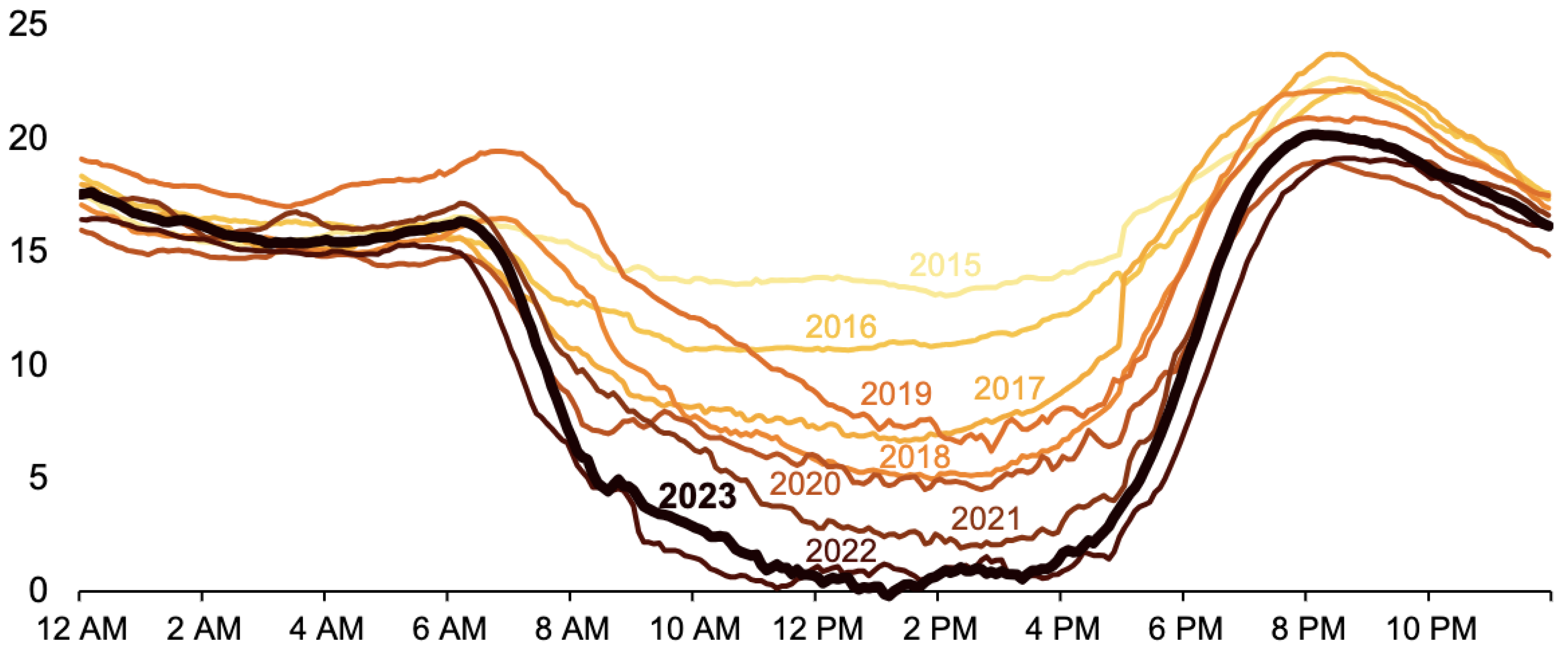
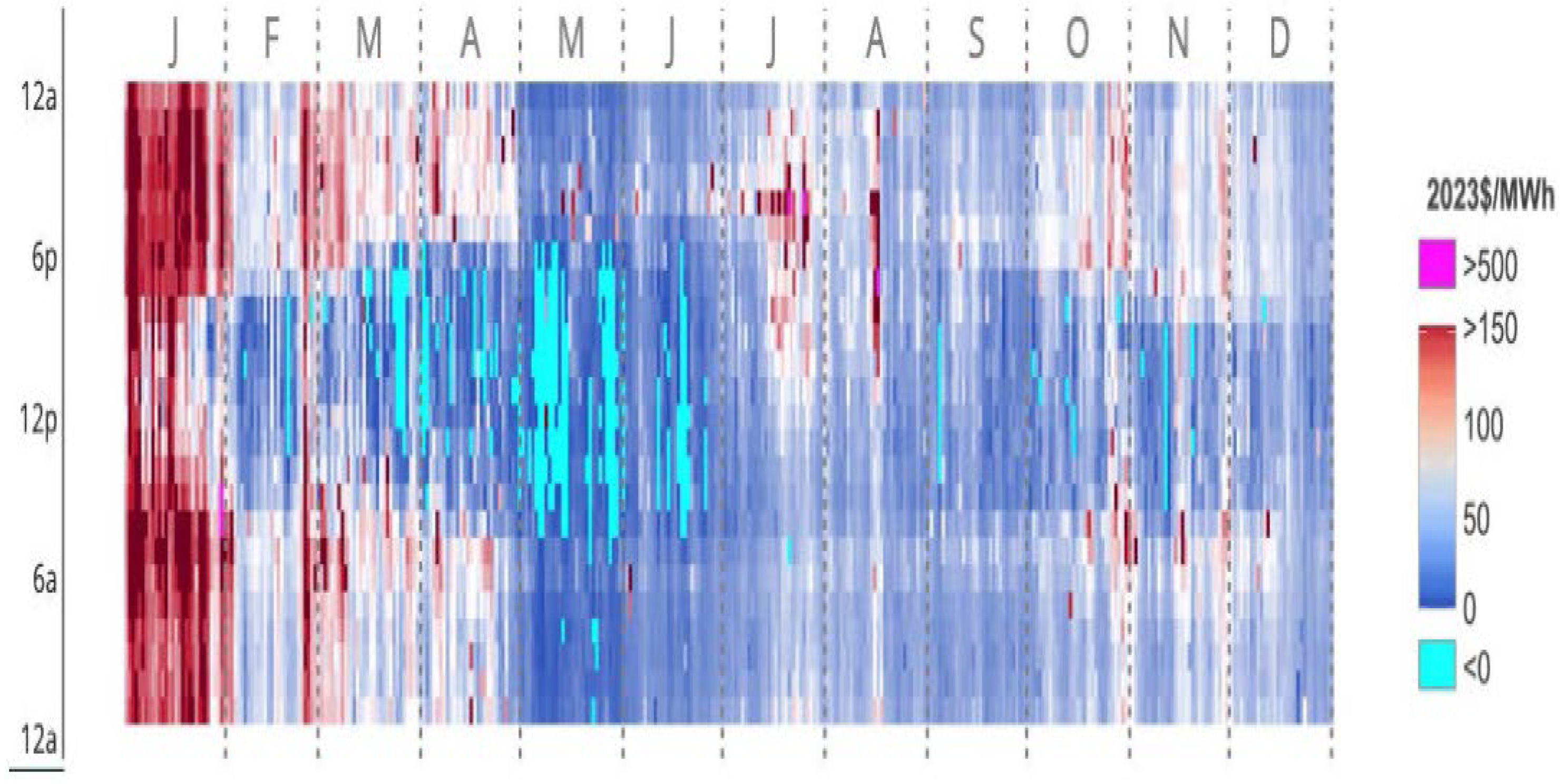
Figure 3.
System Design for Base-load Reactors with Dispatchable Electricity.
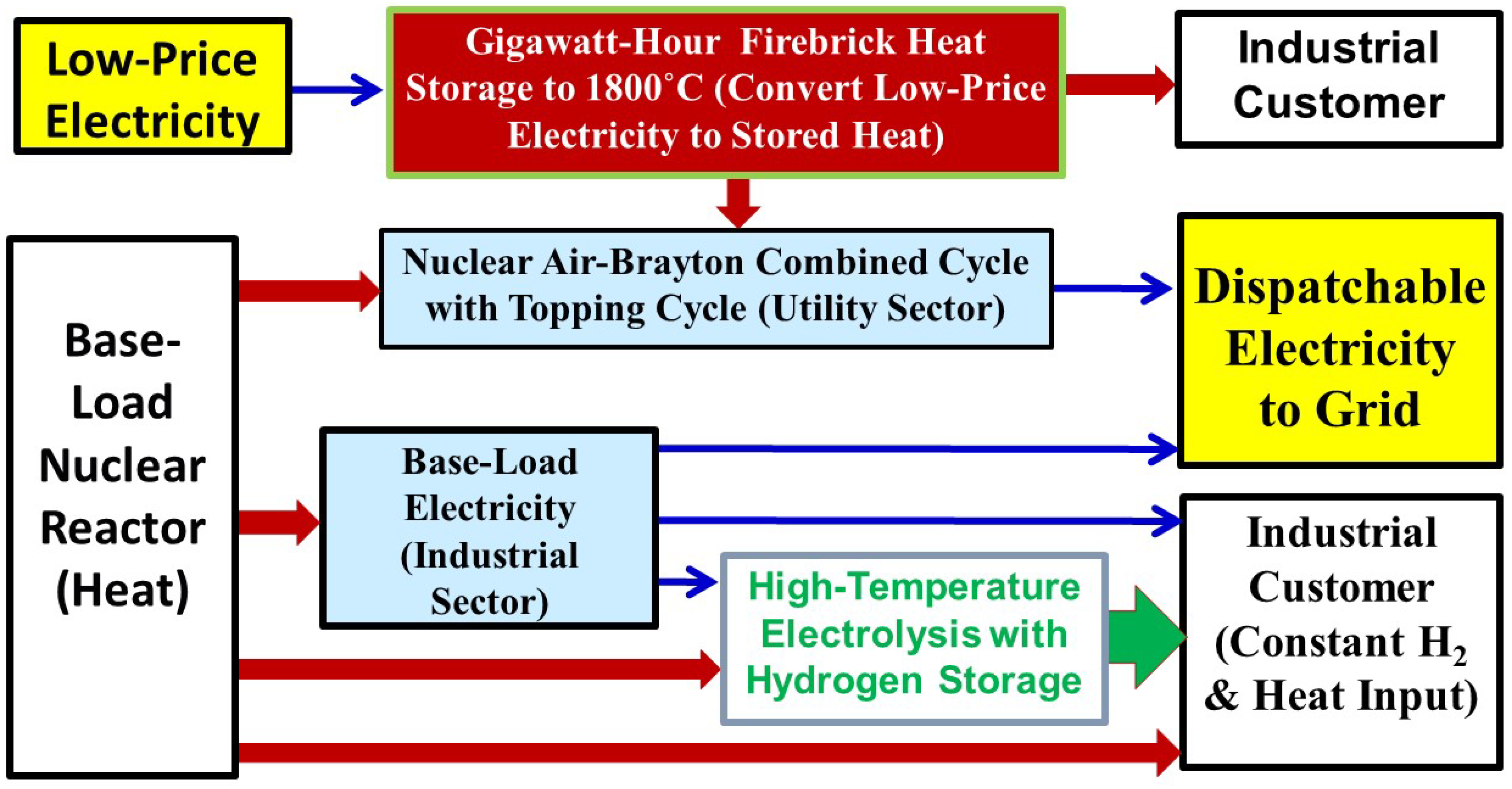
Figure 4.
Generic High-temperature Firebrick System Coupled to Utility and Industrial Users.
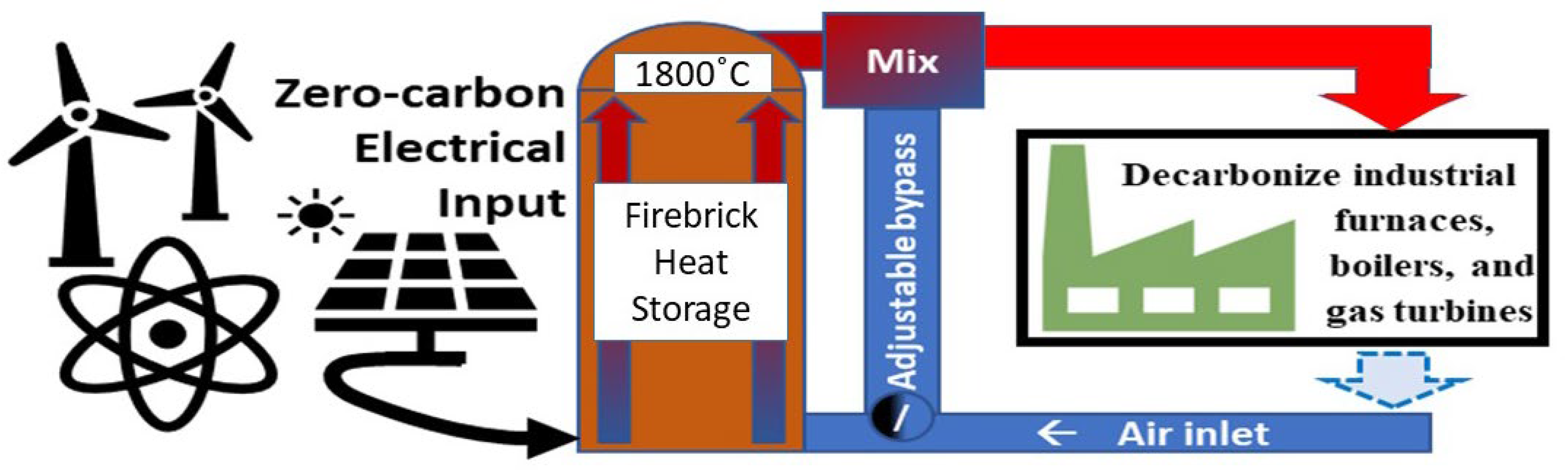
Figure 5.
Cross Section of the Core of the Heat Storage System in Discharge Mode (Patent pending). Heating is by Electrically Conductive Firebrick.
Figure 5.
Cross Section of the Core of the Heat Storage System in Discharge Mode (Patent pending). Heating is by Electrically Conductive Firebrick.
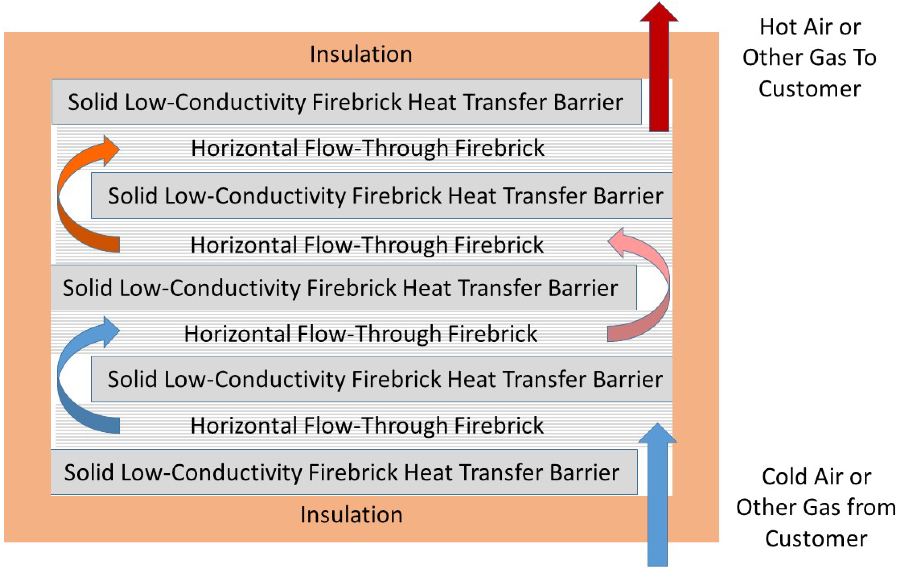
Figure 6.
Cross Section of the Core of the Heat Storage System (Patent pending) in Charging Mode with External Heating of Gas.
Figure 6.
Cross Section of the Core of the Heat Storage System (Patent pending) in Charging Mode with External Heating of Gas.
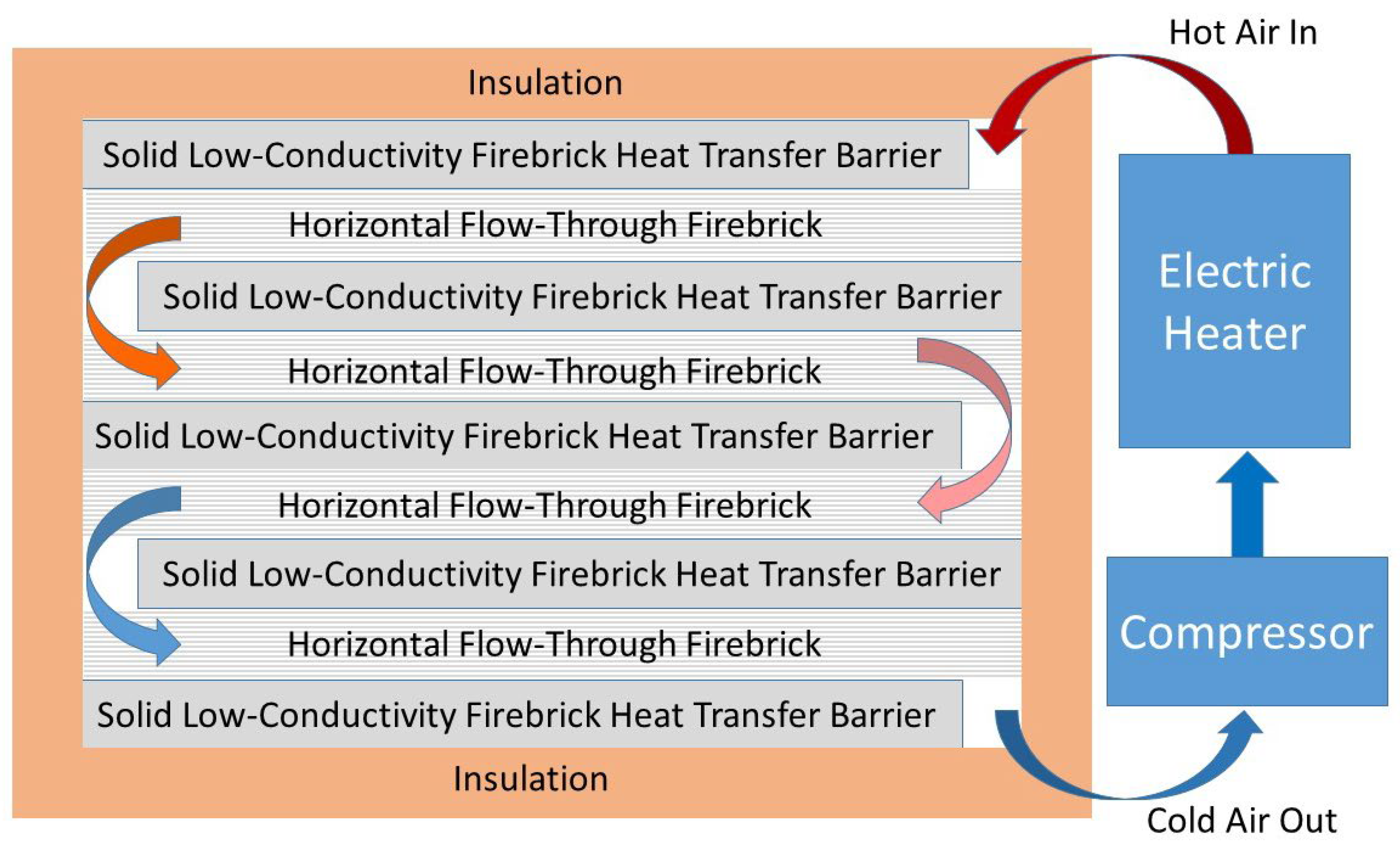
Figure 7.
Nuclear Air Brayton Cycle with Thermodynamic Topping Cycle and Heat Storage [22].
Figure 7.
Nuclear Air Brayton Cycle with Thermodynamic Topping Cycle and Heat Storage [22].
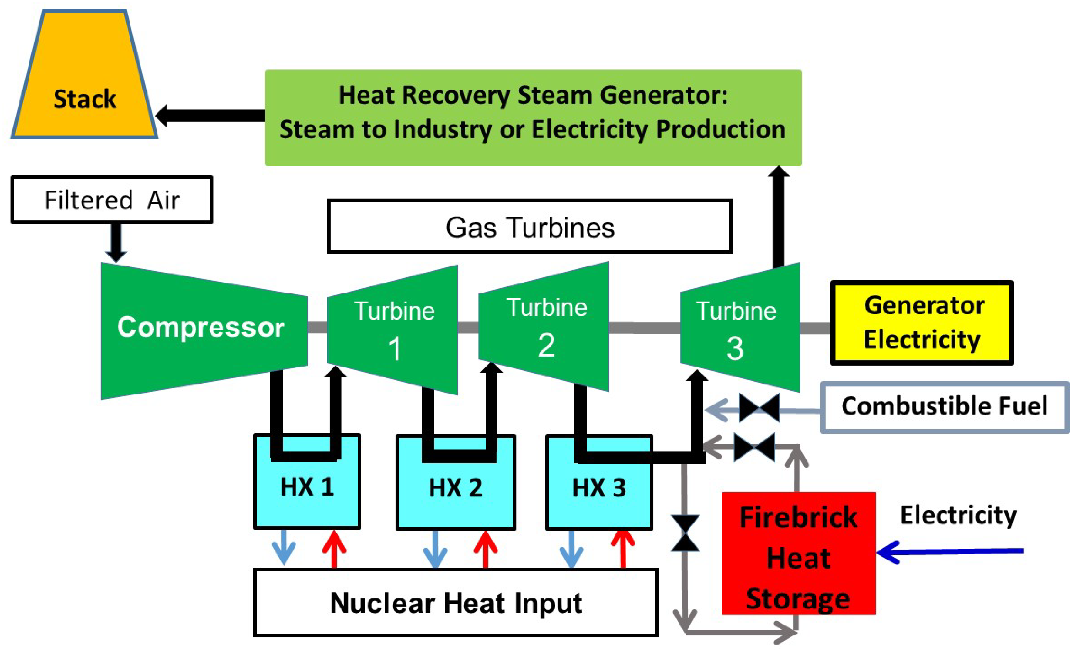
Figure 8.
Nuclear Industrial Stored-Hydrogen, Heat and Electricity System.
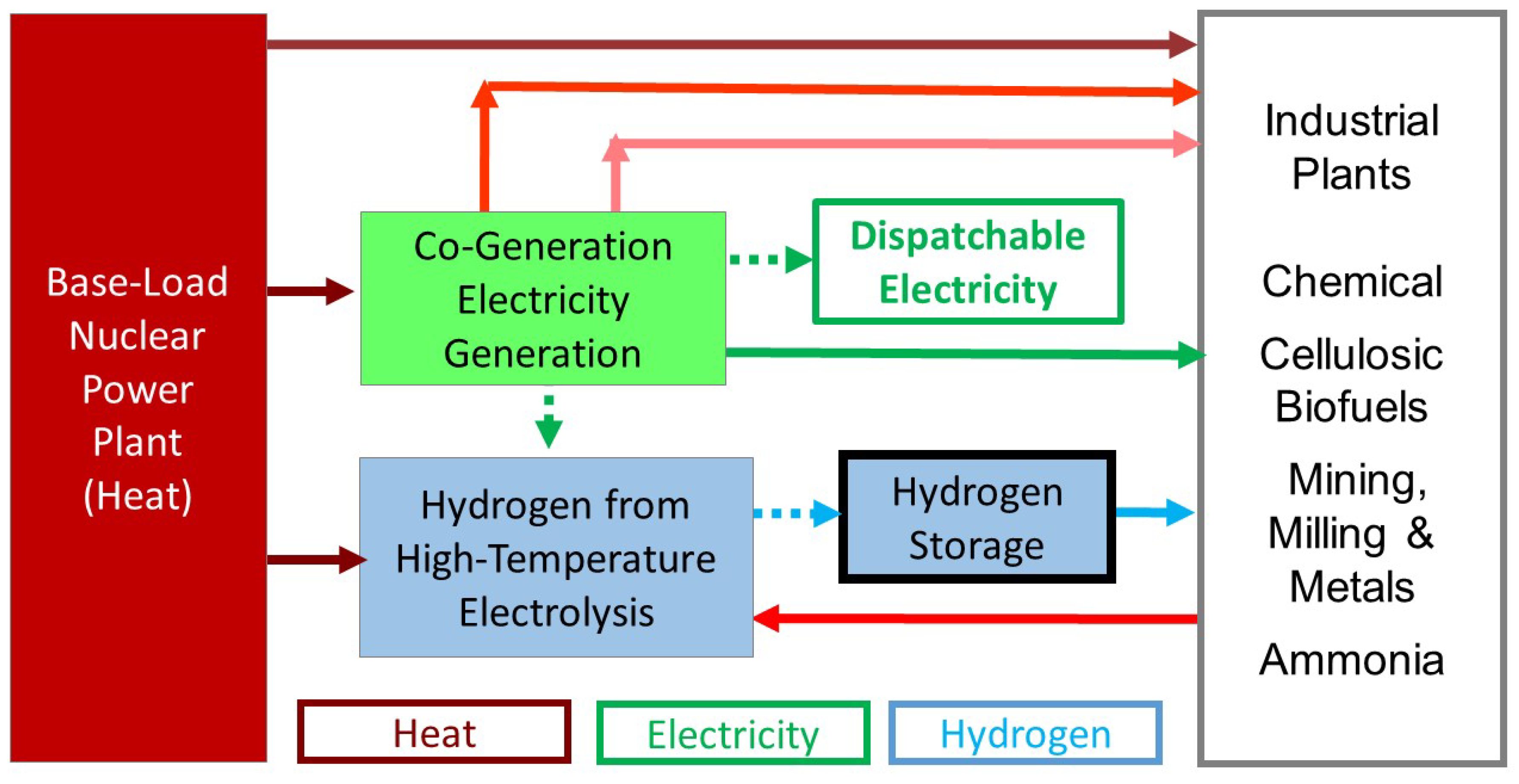
Figure 9.
Nuclear-assisted Cellulosic Hydrocarbon Biofuels Production.
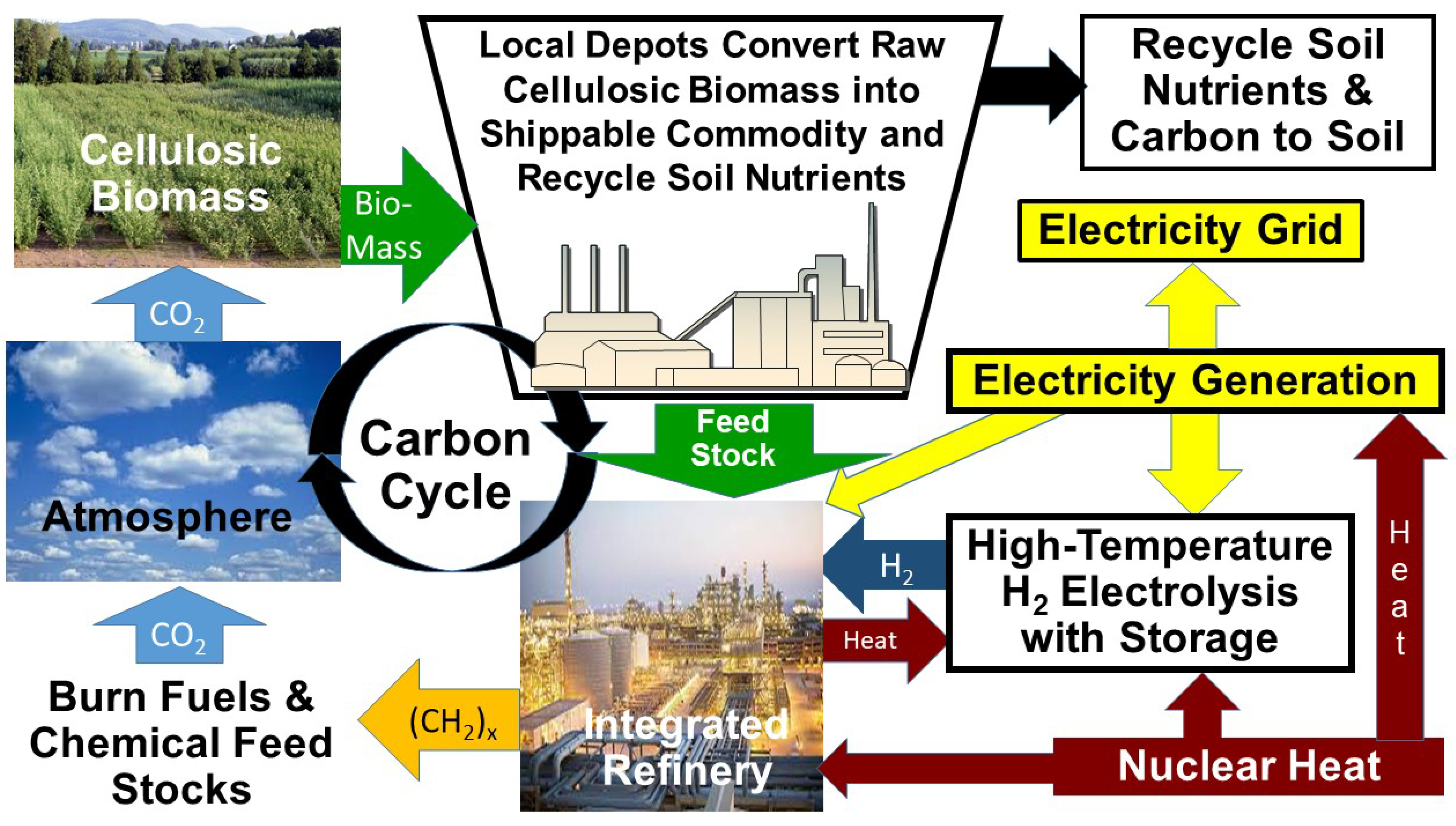

Table 1.
Performance of Different NACC Cycles [22].
Table 1.
Performance of Different NACC Cycles [22].
| Turbine 1&2 Exit Temp | Turbine 3 Nominal Exit Temp | Turbine 3 Boosted Inlet Temp | Base Efficiency | Fraction Base from Steam | Hydrogen Burn Efficiency | Combined Efficiency | Brayton Gain | Overall Gain |
| Sodium Near-Term System (Nominal Inlet Temperature 773 K (500°C) | ||||||||
| 680.5 K | 640.5 K | 1100 K | 32.8% | 18% | 71.1% | 48.4% | 1.464 | 2.522 |
| 680.5 K | 640.5 K | 1700 K | 32.8% | 18% | 74.2% | 60.4% | 2.347 | 5.744 |
| Molten Salt Advanced System (Nominal Inlet Temperature 973 K (700°C) | ||||||||
| 792.5 K | 722.5 K | 1100 K | 45.5% | 24% | 74.5% | 51.1% | 1.168 | 1.403 |
| 792.5 K | 722.5 K | 1700 K | 45.5% | 24% | 75.0% | 61.6% | 1.834 | 3.070 |
Disclaimer/Publisher’s Note: The statements, opinions and data contained in all publications are solely those of the individual author(s) and contributor(s) and not of MDPI and/or the editor(s). MDPI and/or the editor(s) disclaim responsibility for any injury to people or property resulting from any ideas, methods, instructions or products referred to in the content. |
© 2024 by the authors. Licensee MDPI, Basel, Switzerland. This article is an open access article distributed under the terms and conditions of the Creative Commons Attribution (CC BY) license (http://creativecommons.org/licenses/by/4.0/).
Copyright: This open access article is published under a Creative Commons CC BY 4.0 license, which permit the free download, distribution, and reuse, provided that the author and preprint are cited in any reuse.


