
Submitted:
10 December 2024
Posted:
11 December 2024
You are already at the latest version
Abstract
The production of hydrogen via electrolysis, using renewable power and sustainable water sources, is critical to energy storage systems and the energy transition. There remain significant industry questions concerning efficiency and degradation of hydrogen production, component lifetimes, hydrogen storage, system maintenance, control methods and end-of-life refurbishment/recycle/salvage that, when answered, enable viable techno-economic analyses of scaled-up systems. Current knowledge of component and systems integration has uncertainty that requires a detailed technical analysis of these industry questions via research-based low regret testbeds. This study details exemplar design and construction of a flexible plug-and-play hybrid renewable power and hydrogen testbed with up to 50 kW electrolysis aimed at addressing these questions. The testbed configuration includes three different solar technologies, three different battery technologies, two different electrolyser technologies, hydrogen storage and a fuel cell for regenerative renewable power. Design constraints include the current limit of an AC microgrid, regulations for grid connected inverters, power connection inefficiencies and regulated hazardous area approval. These constraints can be overcome but additional time and resources are required to re-certify design and construction. We identify, and show resolution of, systems integration challenges encountered during construction that may benefit the energy transition.
Keywords:
renewable hydrogen
; energy systems
; energy storage
; testbeds
; electrolysis
; seawater treatment
1. Introduction
The renewable hydrogen energy industry has a long history and is growing rapidly since the publication of Japan’s Hydrogen and Fuel Cell Strategy in 2017 [1] after which many nations followed [2]. National hydrogen strategies continue to create significant industry interest. Some strategies have been updated [3] confirming industry and policy focus on heavy industry (e.g., iron, alumina), ammonia, heavy transport (shipping, aviation, trucking), power generation and grid support.. The number of announced renewable hydrogen projects has grown to the GW-scale.
Of note is the dramatic increase in the number of projects in the IEA database reported to commence from 2020 and the substantially increased scale of proposed projects from 2025 (Supplementary Figure S1). However, a relatively small number of projects have reached a financial investment decision (FID) to enable operation or construction [4]. As an example, for the 2019–2024 period in Australia, there are approximately 144 projects listed in the national hydrogen database [5]. Of these <10% are operating, ~13% are under construction and a further 42 projects (~29%) are listed as “archived”; a category with a range of interpretations including “not progressing”, “on hold” or “completed study”.
Notwithstanding the impact of a global pandemic and resultant supply chain constraints, the progress of energy transition projects is considered at odds with ambitious policy objectives [6]. The financial and environmental impact of planned GW-scale renewable hydrogen facilities is substantive and requires effective risk mitigation and cost reduction [7,8] given increased community scrutiny and rapidly emerging complementary, or replacement, technologies. These risk factors can only be explicitly identified and managed through a thorough understanding of the technical risks in design, construction, regulatory, operational and end-of-life activities. Therefore, the identification and cost estimates of risks that can be gained from targeted testbed systems are critical processes for the energy transition.
Hybrid renewable power and hydrogen (HRPH) testbeds are integrated energy systems for benchmarking renewable power generation and storage combined with hydrogen production, storage, and end-use technologies. The purpose of HRPH testbeds is to answer significant industry questions that impact renewable hydrogen scale-up and production costs with uncertainties in efficiency and degradation of production, component lifetimes, hydrogen storage, integrated storage of electrons and hydrogen, system efficiency and maintenance, control methods and end-of-life refurbishment/recycle/salvage critical to viable techno-economic analyses.
In this work, we describe system integration challenges that have arisen through construction of an HRPH testbed utilizing multiple technologies with allowance for a flexible system configuration and future addition of other components (and/or additional complexity) as technologies evolve. This approach to testbed design has benefits for
- (i)
- benchmarking performance of different electrolyser and/or fuel cell technologies using a common renewable energy (RE) infrastructure;
- (ii)
- benchmarking performance of different HRPH system configurations; and
- (iii)
- assessing and comparing energy management algorithms across multiple technologies and system configurations.
This testbed is distinguished from single use or single process pilot/demonstration plants previously documented for hydrogen production. For example, power-to-gas pilot plants have been reviewed by Gahleitner [9] with a compendium of valuable lessons that are still relevant today. These lessons include poor harmonisation on reporting practice of designs, limited operational experience and performance of pilot plants; impact on system efficiency due to relative sizing of equipment; different experiences with prototype and commercial grade equipment, lifetimes, and integration challenges.
More recently, power-to-X demonstration projects have been reviewed by Chehade et al. [10] and by Egeland-Eriksen et al. [11] These reviews detail insights from power-to-fuel pilot and demonstration plants for methane and methanol at scales from 6 kW to 12 MW. In 2021, Bargiacchi [12] summarised activities and status of demonstration plants for ammonia production at over 30 MW scale.
Clean Hydrogen Partnerships lists the Hydrogen Valleys worldwide [13] and the International Energy Agency (IEA) provides a database of power-to-X systems [4] updated annually every October. Distributed hydrogen systems will play an important role in the energy transition of remote communities [14]. For comparison, we list in Supplementary Table S1 selected research level HRPH testbeds that are less than GW-scale [15,16,17,18,19,20].
This work describes a research scale pilot plant, named “H2Xport”, as part of a broader Australian Renewable Energy Agency (ARENA) funded programme for Research Development and Demonstration (RD & D) on hybrid RE facilities targeting production, storage and use of hydrogen [21]. An early Queensland exemplar, the Sir Samuel Griffith Building completed in 2013 [19], provided useful guidance for planning and modelling [22,23] of this recent H2Xport installation.
The aim for the H2Xport pilot plant was to construct a flexible, multi-user, RD & D scale HRPH testbed to evaluate renewable hydrogen production systems using water electrolysis from seawater or other sustainable water sources. A key design consideration was to “future-proof” the installation by providing for staged upgrades, or addition of other components, as technologies evolve (i.e., a “plug-and-play”, or PnP, capacity).
In earlier work, we describe a conceptual “Adaptive Renewable Energy Plant” (AREP) [24] that enables a user to configure, or to re-configure, an RE system by modifying the type and scale of technologies as energy supply and demand fluctuates. This adaptive response requires hybrid power (which may include grid power) and PnP capability with flexibility designed into the system configuration.
2. Design Concepts and Methods
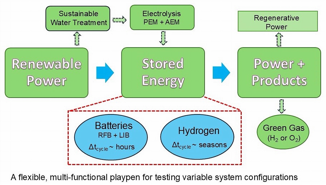
The design concepts considered in this work are shown in Figure 1 based on the outcomes of earlier testbeds listed in Supplementary Table S1 and relevant know-how on industrial scale applications. While the “centerpiece” of Figure 1 emphasizes electrolysis, there are many interrelated factors that impact overall cost, efficiency, and reliability of renewable hydrogen production. A further benefit of flexible testbed systems is to enable many of these interrelated factors to be tested, evaluated and potentially improved or discarded. These testbeds provide industry and government with a sound basis for commercial construction and operation as well as for policy direction.
A target outcome for the H2Xport testbed is to evaluate whether the AREP concept can be realized in practice. Other relevant studies that provided early indicators for planning and operation of the H2Xport testbed, include an analytical model to size the operational components [25] of a system and high resolution solar data from hybrid PV energy generation [26]. This work describes the final as-built construction of the testbed and a range of constraints – technological, regulatory, operational, and market – that arose during implementation. We defer reporting on testbed system performance to a subsequent publication.
3. Results
The H2Xport HRPH testbed is a research-scale testing platform with performance benchmarking capacity for commercial RE assets and new prototype technologies at small pilot scale (i.e., < 50 kW). Key design considerations include industry questions that impact renewable hydrogen scale-up such as
- (i)
- the lifetime of electrolysers powered from variable RE with use factors [27] for water from different sustainable sources,
- (ii)
- system material and component lifetimes with hydrogen demand undergoing temperature and pressure swings,
- (iii)
- long-term system efficiency impacted by electrolyser degradation,
- (iv)
- choice of technologies and efficient system configuration(s), and
- (v)
- control methods to integrate and operate multiple technologies, or new equipment, as a system ages.
These fundamental design and construction issues impact cost of hydrogen and are incorporated into the summary design concepts shown in Figure 1.
3.1. HRPH Testbed Layout
An aerial view of the constructed HRPH H2Xport testbed is shown in Figure 2. The HRPH testbed is on a leased site of approximately 600 m2 inside the Queensland Department of Agriculture and Fisheries (QDAF) Redlands Research Facility (Supplementary Figure S2). The site is connected to the Energex electricity distribution system in Southeast Queensland (SEQ). The final layout of the testbed as of December 2023, is schematically shown in Figure 3 and as a General Arrangement Drawing in Supplementary Figure S3.
Key assets of the testbed listed in Table 1 are shown in the block diagram in Supplementary Figure S4. These assets reflect the proposed concept except for the original plan to produce hydrogen via a DC microgrid. Details on the microgrid design and reasons for not using DC-based hydrogen production are given below. In general, the design brief allows for individual components (e.g., a redox flow battery or a Li-ion battery) to be operated singly or in concert with other components within the H2Xport testbed.
Integration of electrolysers with water sources, water treatment and reuse, and the need to minimise water consumption in countries such as Australia is important for scaling the hydrogen production industry and is a key criterion included in this HRPH testbed design. There are two sustainable sources of water to supply electrolysers:
- (i)
- rainwater from the shed roof captured in tanks filtered to equivalent potable water quality and
- (ii)
Municipal water is connected but only used as a reserve emergency supply. Further details on the water system are provided below.
Hydrogen production (e.g., via electrolysis), hydrogen storage and hydrogen use (e.g., via a fuel cell) are central elements of the HRPH testbed. For hydrogen production or use assets, a key timeline consideration is the serial progression of engineering and hazardous area (HA) assessments prior to HA certification and a final HA audit. This design and construction, assessment, re-engineering, certification, and audit progression is a critical execution timeline required in order to “switch on” hydrogen equipment compliant with state and national government regulations. Further detail on key design and construction activities to achieve regulatory compliance is provided below.
3.2. Power Microgrid
At commencement of project, it was proposed to install a fully DC microgrid with the assumption that key components, such as electrolysers, batteries and fuel cells could operate in DC mode. After extensive enquiries and discussion, the microgrid concept reverted to design and construction of a 400Vac 3-phase microgrid shown in Supplementary Figure S5. Reasons for this change to concept design are provided in Section 3.2.3.
3.2.1. Site Considerations
The AC microgrid design has a common infrastructure backbone terminating at grid compliant inverters on the power generation side. This infrastructure included a main switchboard that integrates grid connection, power generation and load panels with eight DC/AC power converters. The AC microgrid is connected to mains power with a separate meter associated with the site lease within the DAF facility. This meter ensures grid connection compliance for a maximum generating capacity of 83kVA based on aggregate inverter power ratings.
All RE generating assets with DC voltage outputs are connected to the 400Vac 3-phase microgrid via inverters (Supplementary Table S2) that are approved devices on the Australian Clean Energy Council list [30]. The use of these devices is a requirement for grid connection compliance. The H2Xport microgrid has unrestricted export of renewable power on-site that is largely consumed within the broader DAF facility with significant loads from temperature-controlled horticultural buildings. Excess power from the HRHP microgrid is exported past the DAF meter to the SEQ mains grid.
Currently, the DAF site has less than 30% renewable electricity, but this proportion is anticipated to increase to >80% renewable power and 90% lower electricity emissions by 2035 compared to 2005 levels [31]. Therefore, to produce hydrogen from electrolysis at the testbed using power with a high percentage of renewables, the import of power from the main grid is limited by electrolyser power levels less than that available from the connected solar power.
The import of mains power, currently with high carbon intensity, is available as backup power given the testbed nature of the facility, and because commercial electrolysers generally specify that power must be maintained at all times. A capacity to export and/or import grid power also enables future exploration of grid-firming and power management of local DAF loads. Power management for the broader DAF site is possible with further consideration of fuel cell capacity and revised sizing of hydrogen storage.
3.2.2. Power Assets
Electrical power assets include
- (i)
- solar arrays with up to 1000Vdc output connected to Fronius inverters with Maximum Power Point Tracking (MPPT),
- (ii)
- redox flow and lithium ion batteries (3 kW to 5 kW) and
- (iii)
- a 5 kW Proton Exchange Membrane (PEM) fuel cell,
all components with 48Vdc connection to Deye hybrid inverters. Deye inverters are connected to the HRPH testbed AC microgrid behind the meter.
Commercial electrolysers contain in-built rectifiers and are connected directly to the microgrid by a 400Vac 3-phase connection (Nel H6 electrolyser) or 240 Vac single-phase connection (Enapter EL4.0 electrolyser). The Enapter electrolyser consists of four separate electrolysis modules with single phase connection distributed across the three phases to balance loads on each phase.
Powertags (Schneider Electric) are installed in the microgrid on each of the electrical connections to the RE assets within the pilot plant, providing measurement and analytics for power levels and energy flows in the microgrid. Each RE asset can be individually isolated from the microgrid via a manual switch that in future can be changed to a switch compatible with a Programmable Logic Controller (PLC).
On the hydrogen production side of the HRPH testbed, there is greater flexibility for selection and connection of electrolysers because they are a power load within the local microgrid and thus, not constrained in size by electricity regulation. On the other hand, the selection of electrolysers is constrained by the current rating of the microgrid (250 A) and hydrogen output limitations as noted below.
Implementation of the PnP HRPH testbed with multiple RE generation and with load assets of different technologies creates new technical challenges in dynamic power behaviour. A key issue is that the voltage and frequency stability on the AC microgrid must be guaranteed by regulating AC voltage inputs to the microgrid from each individual power generating device. We approach this issue by using individual grid connected power conversion devices (solar inverters, battery bidirectional inverters and a fuel cell inverter) for each of the power generating assets (Supplementary Table S2). In this way, the deployment and connection approval for power convertors are regulated by local authorities.
Behind the power converter, on the DC generation side, there is flexibility to swap out the power generating asset provided that the rated power capacity of the power converter is compliant with the electricity regulator’s requirements (often fixed at the time of approval). Changes to the power converters are possible with a new application for compliance but with substantial time and cost implications. This configuration achieves stability of the AC microgrid with inverters switched offline when frequency and/or voltage is outside that defined by grid compliance.
3.2.3. Micro-Grid Challenges
The original design for a full DC microgrid using a 380-400Vdc bus was not implemented for three reasons
- (i)
- the limited availability of commercial DC–DC solar converters with Maximum Power Point Tracking (MPPT) in the 25 kW range,
- (ii)
- limited availability of bi-directional 48Vdc/380Vdc power converters in the 5 kW to 10 kW power range,
- (iii)
- absence of commercial electrolysers with DC input capability; consequently, prototypes or early versions were prohibitively expensive and,
- (iv)
- no availability of DC–DC power conversion devices on the Australian Clean Energy Council list of approved inverters to enable grid connection compliance.
These issues remain today, but when resolved, a 380-400Vdc microgrid should be possible following a similar design configuration as described here for an AC microgrid. Such a DC–DC enabled microgrid is likely to deliver additional system efficiencies (up to 10%) based on modelling with laboratory-scale experiments of similar topology [32].
3.3. Electrolyser Configurations
The HRPH testbed was designed and constructed with a capacity to assess and improve key performance measures with respect to each electrolyser including:
- (i)
- consumption rates of source water,
- (ii)
- consumption of renewable electricity for water treatment and supply,
- (iii)
- quality of water at specific process steps,
- (iv)
- potential for waste heat utilisation and
- (v)
- volume and composition of reject water streams for treatment and/or re-use.
The HRPH testbed includes an Enapter electrolyser based on Anion Exchange Membrane (AEM) technology, and a Nel H6 electrolyser based on Proton Exchange Membrane (PEM) technology. The consumption rates for high purity water required by the Enapter EL4.0 electrolyser and Nel Electrolyser are specified as 0.42 L/hr [33] and 5.5 L/hr [34], respectively. These rates are nine times the specified hydrogen mass production rate of 0.5 Nm3/hr and 6 Nm3/hr for the Enapter EL4.0 and Nel H6, respectively, as predicted by the stoichiometry of the water electrolysis reaction.
Both electrolysers monitor hydrogen production and automatically stop production if either the inlet water pressure or quality is not to specification. If either event occurs during the day with the HRPH testbed, then excess solar power is used to either charge batteries and/or export to the mains grid. Cooling equipment is connected to the larger Nel H6 electrolyser adding to the total water consumption for hydrogen production. The adiabatic chiller included in the HRPH testbed consumes up to 20 L/day of potable water.
On the other hand, the smaller Enapter EL4.0 electrolyser modules are air cooled and do not require extra water for cooling and thus, at this modest scale, minimises water consumption. Water use and re-use is an important factor for large scale hydrogen production plants. However, use of air-cooled electrolysers is currently not viable for larger, MW-scale modules.
3.4. Water Utilisation
The operating principles for water supply to the electrolysers are to minimise the use of municipal potable water and to provide a reliable supply of high purity water for electrolysis. Sustainable water sources for industrial scale renewable hydrogen production are considered to be seawater from suitable offshore coastal locations [35] and wastewater treatment plants [36].
The HRPH testbed has a range of instrumentation for data analytics to determine the relationships between water source, treated water quality and electrolyser performance for the two types of electrolyser technologies. Power consumption by the MD plant, rainwater pumps, chiller unit and RO units is measured and used in aggregate system performance analytics. Opportunities for improved water efficiency and reduced energy consumption will be driven by recycling of waste streams through the MD treatment process and thermal integration of the MD process with waste heat recovery from electrolysis [37].
3.4.1. Water Supply
To achieve water volume demand and water quality, the HRPH testbed has two principal and back-up water source(s) and two water treatment methods as shown schematically in Figure 4. The primary water source is seawater, from the Moreton Bay coastline in South-East Queensland, outside Marine Park boundaries. This seawater is tanked to the HRPH site, pumped into holding tanks, and treated by the MD system.
Rainwater from the shed roof, covered by SiPV solar panels, is the second principal water source that is captured in two 5,000 L rainwater tanks and filtered to potable water quality. Municipal water is connected as a backup supply given the testbed nature of the HRPH facility. Each electrolyser has a separate RO water treatment unit that further purifies the MD-treated water to the quality specified by electrolyser manufacturers.
Reject water from various locations in the HRPH testbed is initially sent to waste and opportunities for water recycling are evident for future implementation. Each electrolyser contains an internal recirculating electrolyte solution loop that accumulates various materials from exposed surfaces during operation. At scheduled maintenance periods, typically when electrolyte conductivity is above the manufacturer’s determined upper limit, the reject solution is disposed as chemical waste. Drain streams from RO units can be four times the flow rate of the pure water feed to electrolysers. For modest sized electrolysers, RO reject water may be sent to storm water outlets.
3.4.2. Water Quality
AEM and PEM manufacturers specify requirements for water purity of < 5 μS/cm [33] and < 1 μS/cm [34], respectively. The different purity requirements reflect the differences in electrode material and membrane degradation behaviour by alkaline and acidic water electrolysis methods, respectively [38].
Membrane Distillation (MD) technology [39] is a thermally driven process that can provide quality pre-treatment of saline waters for further use at purity less than 10 μS/cm [40] . Utilising waste heat from water electrolysis reduces electricity consumption in water supply and treatment. Integration of MD into the HRPH to utilise waste heat to reduce energy load and to minimise cooling water consumption is described in detail in the work by Arthur et al. [37].
A future implementation stage would include recycling the RO drain water to the input of an MD process (or similar quality process) to increase water utilisation efficiency. The composition of reject water from the adiabatic chiller is expected to be little different to an input water stream. Hence, in water scarce regions, recycling reject water to the input of the MD process for re-treatment could be implemented.
The waste stream from the MD process that treats seawater will have high salinity that cannot be disposed in storm water drains. In this case, a high salinity waste stream will be disposed as chemical waste and in future may be considered a source of valuable elements (e.g., Ca, Mg) or salts. In the HRPH system, the composition and volume of reject water streams can be routinely measured. These measurements enable development alternative processes to decrease source and reject water volumes for increased water efficiency and reduced environmental impact.
3.5. Electrolyser Integration
The two commercial electrolysers are installed in a 20ft container (Nel H6) and a demountable/portable building of similar size (Enapter EL4.0), respectively. Both the container and demountable/portable shed are fitted with the required safety devices and protection by ventilation as discussed in Section 3.6.
3.5.1. Gas Control and Storage
PEM and AEM electrolysers produce hydrogen with internal hydrogen gas pressures increasing to the level set by a back pressure valve. Hydrogen gas is produced from the electrolysers at 30 bar to match the maximum working pressure of the hydrogen storage vessel. The Enapter EL4.0 is supplied with default 35 bar operation that was changed to 30 bar during commissioning.
Hydrogen gas is dried and stored in stainless steel 316 vessels for use in fuel cell applications that require 99.97% purity [41]. Hydrogen gas is produced at specified purity > 99% [33] and > 99.99% [34] from the Enapter EL4.0 and Nel H6 electrolysers, respectively. The latter system has an inbuilt pressure swing absorption unit to dry the hydrogen to a lower dew point. Hydrogen produced from Enapter EL4.0 modules is connected to an Enapter DRY2.1 module that is a temperature swing absorption dryer with hydrogen output specified at > 99.99% purity.
The hydrogen produced from the Enapter DRY2.1 module is reticulated via an instrument panel containing a moisture sensor and is located outdoors in the HRPH testbed. Hydrogen produced from the Nel H6 electrolyser is measured by an external moisture sensor in the HRPH testbed located inside the container. Dried hydrogen gases from both electrolysers are stored in the 2.5 m3 storage vessel at pressures up to 30 bar. A hydrogen gas sampling port at the storage vessel allows small volumes of stored gas to be tested for purity using Gas Chromatography (GC) analysis.
Oxygen is co-produced with hydrogen by each electrolyser and this practice offers interesting off-take applications such as in wastewater aeration and energy demand shifting [36,42]. The oxygen produced from EL4.0 modules are currently aggregated and vented to a safe location away from hazardous zones. Currently, the oxygen produced by the Nel H6 is dispersed in the container and diluted by air using safety fans to ensure that the electrolyser cabinet remains non-hazardous.
A key factor, not only for factory performance criteria, but also for practical installation in the field, is hydrogen “cross-over” in the oxygen output stream (and vice versa) of an electrolyser [43]. The extent of hydrogen cross-over substantially influences the capacity of electrolysers to dynamically respond to intermittent power supply and thus, determines the level of power turndown required to reduce the hydrogen production rate.
3.5.2. Gas Sensing and Monitoring
The Nel H6 electrolyser contains a hydrogen sensor at the oxygen release location inside the electrolyser to detect hydrogen cross-over within the PEM. This sensing capability is important for safe operation at low loads (low hydrogen production rates) when supplied by variable renewable electricity. The PEM control logic stops hydrogen production if levels become unsafe.
In contrast, the Enapter EL4.0 electrolyser does not provide such monitoring and control. The inclusion of a hydrogen sensor allows the Nel H6 to specify a power turn down range from full power to zero power. The Enapter electrolyser specifications invoke a minimum power level at 60% of full power when one individual module is operating. With more than one module operating, this specification is not invoked when many modules are interconnected at large scale. Consequently, the HRPH testbed, with four EL4.0 modules, has an aggregate turn down capacity to 15% of full power.
Moisture sensors, regular sampling and GC testing are used within the HRPH testbed to monitor and/or stop hydrogen production if the purity is lower than specified by reference standards [41]. In addition to purity measurements, outdoor instrumentation panels in the HRPH testbed enable independent monitoring of the gas pressure, temperature, and flow from each electrolyser as shown in the hydrogen system schematic in Figure 5. A list of installed instruments is provided in Supplementary Table S3.
We note that hydrogen gas has an indirect global warming potential [44]. Large scale hydrogen production plants and downstream value chains need to consider the impact of hydrogen emissions from production processes. Electrolysers undergo hydrogen venting when they are depressurised after hydrogen production has stopped. This venting may occur daily if operation is solely based on intermittent solar power. Venting may also occur less frequently for safety reasons. Depressurisation events quickly release small quantities of hydrogen from the internal piping of the electrolyser to the atmosphere via separately reticulated vent lines to safe locations outside a contained area. The frequency and quantity of such events can be monitored in the HRPH testbed to determine the potential environmental impact of scaled-up industrial plants.
3.6. Fuel Cell and Battery Integration
A longitudinal study over a period of two years at the site of the HRPH testbed [26] showed that low solar insolation often occurs between November and March due to Brisbane’s seasonal weather pattern. This longitudinal study [26] and design of the HRPH emphasised the need for systems thinking for effective utilisation of RE and obviates discipline- or profession-specific bias.
Weather forecasting and our site-specific solar data provides advanced notice of such insolation periods so that appropriate energy management protocols enable full charges for batteries and viable hydrogen storage before adverse weather event(s). When fully charged, the combination of multiple batteries in Electron Energy Storage (EES) provides 60 kWh while the Hydrogen Energy Storage (HES) in the low pressure (30 bar) tank provides 220 kWh of RE. The latter storage equates to about 100 kWh of electricity that can be regenerated from the fuel cell depending on efficiency. The minimum power consumption of the HRPH testbed is less than 2 kW. The combined EES and HES capacity can sustain the HRPH testbed at minimum power level for about 80 hours.
3.6.1. Fuel Cell Sizing
A 5 kW PS5 Powercell PEM fuel cell [45] with 48Vdc connection is housed in the same 20ft container as the Nel H6 electrolyser. The fuel cell is connected to the AC microgrid via a Deye hybrid inverter (Supplementary Table S2). Hydrogen is piped into the container and connected to the fuel cell from the external 30 bar storage via an instrument panel that regulates the pressure required for the fuel cell and independently measures flow, pressure, and temperature (Figure 5).
The fuel cell is sized so that the power rating is matched to the battery power ratings (~5 kW) and is higher than the base level overnight power demand for the HRPH testbed (< 2 kW). We calculated on the basis of earlier solar data [25] that about 1% of annual solar energy will be consumed by the fuel cell when using stored RE to recharge depleted batteries during extended periods of low solar insolation.
The hydrogen consumption rate in the fuel cell when generating maximum power is also a key parameter [25] that influences the level of stored hydrogen available for overnight depletion. The PS5 Powercell PEM fuel cell specifications [45] state that hydrogen is consumed at 3.97 Nm3/hr (start-of-life, sol) to 5.67 Nm3/hr (end-of-life, eol) when operating at maximum 5 kW power. On this basis, the 2.5 m3 hydrogen storage will take between 11 h and 16 h (eol to sol) to decrease from full pressure (30 bar) to a minimum pressure defined by the fuel cell inlet pressure (5 bar).
During commissioning or operation of the plant, there may be no facility to export hydrogen or, if available, there may be times when off-take is not possible. In this case, the fuel cell is operated overnight to deplete hydrogen from storage. This process step enables subsequent electrolyser operation in order to fulfil extant experimental testing programs. In this case, the hydrogen flow meter measurement on the supply line to the fuel cell can be used analytically as an equivalent hydrogen amount that would otherwise be exported. This HRPH use case is also a demonstration of an end use for long duration hydrogen storage to power other applications or devices and for studies related to lifetime operation of fuel cells with daily cycling.
3.6.2. Battery Power and Capacity
Battery power rating(s) should be higher than the electrolyser idle/standby power level (i.e., the lowest power level with no hydrogen production) and the battery capacity should be high enough to sustain continuous operation at lowest power demand for over 24 h. In the HRPH testbed, the rated power of the batteries is between 3 kW and 5 kW. This power rating is above the low load level for the HRPH testbed of < 2kW while the combined capacity of all batteries is 60 kWh. Thus, with current design a minimum power level from batteries can be sustained for one to two days.
Battery capacity is flexible in that system design provides the freedom to increase capacity by adding batteries in parallel to the same hybrid inverter. However, the power rating is constrained by the characteristics of the fixed DC to AC inverter. For example, batteries installed in the HRPH testbed include a RedEarth LiB with nine Troppos batteries connected in parallel and a Redflow battery with two ZBM3 Zn/Br flow batteries connected in parallel. If needed, further additions are possible to increase capacity, or to alter charge and discharge rates to impact battery lifecycle(s).
3.7. System Safety
Safe generation and use of hydrogen is a major concern for those operating or managing an HRPH testbed. Responsible consideration of hydrogen safety imposes significant constraints on the flexible PnP capability of the HRPH. Design and construction of the testbed for electrolysers and fuel cell installation with hydrogen piping, instrumentation and low-pressure storage was performed and certified to the relevant hydrogen regulations. These regulations encompass three legislated Acts in Queensland, Australia:
Three levels of safety control were established early in the design of the HRPH testbed as key risk mitigation strategies to facilitate regulatory outcomes. These levels encompass the HRPH site, containers or portable sheds and equipment. Of note is that this HRPH testbed was designed and largely constructed during the timeframe that the new Queensland Hydrogen Code of Practice was undergoing consultation prior to draft publication in September 2022 [49].
3.7.1. HRPH Testbed Site
The hydrogen storage, instrument panels and equipment housing are contained outdoors in a fenced restricted access hard stand area. A two-hour specified fire wall separates the outdoor hydrogen equipment zone from the shed containing the batteries, electricity panels and IT equipment. The high diffusion rates of hydrogen with wind flows at the testbed site provide inherent protection by rapid dilution of hydrogen below the lower explosive limit. Hydrogen has low ignition energy [50] and this risk is further mitigated by ensuring that no sources of potential ignition and no combustible materials are within the fenced boundary of the HRPH testbed.
As a further layer of protection, the HRPH testbed Emergency Electrical Shutdown (ESD) is a site-wide safety system that includes a Rosemount 975HR Multi-Spectrum Infrared Hydrogen Flame Detector with a field of view covering all outdoor hydrogen equipment housings, reticulation, and storage. If alarmed, the flame detector and emergency stop buttons isolate all power to the equipment by opening relays in the HRPH testbed power board. The HRPH testbed site includes lightning protection electrically connected to the in-slab earth loop that provides equipotential for all connected metal items to eliminate static discharge risks. Lastly, the site safety management system includes restricted access, work permits and evacuation procedures.
The constraints imposed by safety systems and regulations are significant when new, or additional, electrolyser and fuel cell equipment is considered. For example, attention is required for:
- (i)
- updating the hazardous area certificate (HAC) and subsequent audit in order to remain in compliance with the Electrical Safety Act; especially pertinent if there are changes to electrical equipment in hazardous area zones and to the hazardous area verification dossier,
- (ii)
- revising the cause and effect matrix if integration of new/additional electrolysers and fuel cells requires changes to the ESD circuit logic to isolate power, and
- (iii)
- implementing a more stringent HAC assessment including further design/engineering to achieve conformance to standards and regulatory approval if prototype equipment does not have equipment certification.
3.7.2. Equipment and Housing
Hydrogen generation equipment is housed so that each component has independent protection by ventilated safety systems to ensure hydrogen concentration remains below 25% of the lower explosive limit. The Enapter ventilation system is based on a fan that forces non-hazardous outside air to flow through the demountable/portable shed to dilute hydrogen if present. In contrast, ventilation within the NEL container is based on an extraction system.
Critical monitoring devices inside the containers (air flow switches and gas detectors) are used to monitor the status of protection by the ventilation system and are connected to the HRPH testbed ESD system. The HRPH testbed ESD automatically opens electrical relays in the power distribution board that isolate power and accordingly, stops operation of the electrolyser and fuel cell equipment when triggered by an unsafe state. Nitrogen gas activated control valves are also closed by the ESD in order to isolate the hydrogen reticulation and storage system. When power is isolated to the electrolysers, they automatically activate internal valves that fail-safe open to depressurise the equipment with safe hydrogen venting.
The key equipment (Enapter electrolyser, Nel electrolyser and Powercell fuel cell) were selected because they were supplied by manufacturers conforming to specified international safety standards and certifying bodies. These items contain embedded automatic safety systems, independent of their process control logic, monitoring the safe operation of the equipment with automatic shutdown function. The individual equipment safety systems operate independently of each other and of the HRPH testbed safety system.
3.8. Designed System Flexibility
The HRPH testbed has flexibility designed and built into the system at both system and plug and play levels. Deliberate design of system flexibility is in comparison to many known and relevant hydrogen testbeds documented at this time. Key details for other testbeds are listed in Supplementary Table S1.
RE assets in the HRPH testbed can be physically connected or isolated as:
- (i)
- an AC microgrid configuration in which power converters connected to generating assets and electrolyser load circuits, whether connected or isolated from the microgrid, provide 72 combinations of solar-battery-electrolyser configurations, as schematically shown in Supplementary Figure S4. These configurations are constrained by relative power ratings of equipment and the desired test scenario.
- (ii)
- two sustainable water sources and two treatment technologies provide additional technology combinations with the RE source combinations as schematically shown in Figure 4.
The HRPH testbed has several RE assets that can be removed, added or swapped within the following constraints:
- (i)
- selection of specific power generating assets (solar, batteries and fuel cell) connected to the HRPH testbed are constrained by the rating of the (regulated) fixed inverters as defined in Supplementary Table S3. Adding or swapping existing approved inverters is possible in order to provide further flexibility, but this incurs a repeat of the regulatory approval process with cost and time implications.
- (ii)
- selection of load assets (electrolysers) is constrained by the scale of renewable power generating assets, hydrogen pressure, purity and storage requirements, and hazardous area regulatory approval. Nevertheless, the additional time cost to achieve regulatory approval should be reduced with practised implementation on a specific site.
The power rating of the two electrolysers (10 kW and 40 kW) is not constrained by regulated connection approvals because they are a power load in the microgrid circuit. An operational constraint is the limit imposed by the power rating of RE generation (50 kW). Otherwise, to increase hydrogen production at a higher power rating, mains power is required. Alternatively, at the current RE power rating, an electrolyser may be de-rated so that it does not operate at full power. Electrolysers have a minimum power turn down level at which hydrogen is generated. RE generation should at least provide this minimum power level to enable hydrogen production via RE rather than depend on mains power.
3.9. System Integration and Functionality
The HRPH testbed is an integrated RE system with mass (hydrogen, water and oxygen) and energy flows (electrons and molecules) as schematically represented in Figure 6. The integrated system is represented by three sections:
- the grid connected AC microgrid;
- electrochemical energy conversion (P2X and X2P); and
- storage of hydrogen, water and, prospectively, oxygen.
The energy and mass flow of the HRPH testbed is schematically shown in Supplementary Figure S6 for different time periods of high, no, and low solar insolation representing full daytime sun, overnight, and twilight (dawn and dusk) or cloud cover periods, respectively. The energy and mass flows are impacted by storage limits shown in Supplementary Table S4. These storage limits are:
- (i)
- state-of-charge (SOC) of electron energy storage (EES) in batteries,
- (ii)
- hydrogen energy storage (HES) levels in the compressed hydrogen gas tank and
- (iii)
- level of treated water storage (TWS).
3.9.1. Minimum Viable Configuration
The complementary performance of CPV and SiPV solar power was evaluated [26] in order to provide an operational and performance basis for a minimal viable configuration (MVC). The HRPH testbed reverts to an MVC with single technologies, as modelled in previous work [25], when only one type of solar, battery and electrolyser technology is physically connected to the AC microgrid. A typical power response of the HRPH testbed in MVC configuration over a 24-hour day is schematically represented by Figure 7.
However, this HRPH testbed has enhanced complexity with multiples of solar PV, batteries and electrolysers integrated into a system. Thus, more than one type of MVC or more complex configurations, are potentially available for evaluation. For example, when both electrolysers are connected to the AC microgrid their combined capability can generate hydrogen using the excess solar power shown in Figure 7, at point (C), rather than exporting renewable electricity.
Decision criteria to operate the second electrolyser, and timing for when sequentially/simultaneously switched on, can depend on the relative states of the Electron Energy Storage (EES), Hydrogen Energy Storage (HES) and external factors such as power demand in the broader DAF facility.
3.9.2. System Optimisation
Using a PLC to automatically control all physical and chemical processes in the integrated system requires that system components can communicate and function effectively together [51]. This requirement for standardised interoperability is not achievable with the mix of power converters, batteries and hydrogen equipment available today. While standardisation of interoperability is now well down the development path [52,53], the HRPH testbed is also a learning platform to test and validate technology advances.
For example, an improved understanding of how to optimise mass and energy flows while also considering impacts to equipment lifetimes is an important and urgent requirement for industrial application. To assess this issue in a preliminary study, a semi-automated batch process was implemented with the HRPH testbed. This first step to increased complexity of operational practices enabled validation and improvement of performance-based algorithms developed in earlier MVC models [25].
A batch process begins by connecting the required equipment to the AC microgrid defined by the configuration of the testbed according to a test scenario. If more than one battery is connected, charge and discharge priorities are set via programming of the hybrid inverters. If the test scenario aims to use both electrolysers, then a priority order in ramp up and down of hydrogen production establishes precedence.
In principle, multi-functional hybrid platforms such as the H2Xport HRPH may also be utilised to benchmark, or compare, relative performance of digital twin software solutions. Data analytics from a batch operation is then translated to a fully automated algorithm via testing and validation on a PLC platform. Further development of this subsequent platform should then be enabled to include machine learning, predictive analytics, AI tools and digital twins.
3.9.3. System Functions
Consolidated design principles inform an operating practice of the HRPH testbed, and enable user configurable selection of solar technology type, electrolyser(s) and battery/batteries. An hierarchical sequence of operational conditions encourages rigorous evaluation of testbed performance while ensuring flexible use minimises system degradation. These generic operational conditions include:
- Electrolyser(s) produce hydrogen only when solar power is available (targeting >99% renewable hydrogen);
- At night or during low solar incidence, the minimum power requirement for electrolysers (i.e., no hydrogen production) is provided from one or more batteries, the fuel cell or mains power in that order of priority;
- Batteries are charged only from solar power; with provision to be charged from renewable re-generative power via the fuel cell and mains power in order of priority;
- Fuel cell(s) are used only for back-up renewable regenerative power when the batteries are depleted in order to supply a minimum power requirement for the electrolysers;
- Any excess power from solar generation is exported to the mains supply for use in local loads within the broader DAF site;
- The power quality of the electrical microgrid must meet safety and reliability measures for AC grids so that all connected equipment is not adversely impacted while operating to specification(s);
- The water input to electrolysers minimises the use of municipal water (targeting >99% sustainable water use);
- If the hydrogen storage vessel is full and there is no off-take available, the fuel cell is operated overnight to deplete hydrogen storage; this step enables on-going testing of electrolysers.
4. Discussion
Testing and evaluating hydrogen systems via research-based testbeds at modest yet meaningful scale (many kW) offers opportunity to reduce commercial risk and to enable solid returns on major investments at commercial scale. However, very few research level HRPH testbeds, typically based at universities, have been constructed at the kW scale. Deploying, using and providing outcomes from such testbeds enables a sector:
- (i)
- to bridge the nexus between lab-based research (typically at sub-kW scale) and industry scale demonstrator projects (now increasing to MW and GW scale); and
- (ii)
- to understand and benchmark how RE generation technologies may connect to different or complementary electrolyser, storage and use technologies.
In contrast to the testbeds around the world of relevance (Supplementary Table S1), the HRPH testbed described in this work has flexibility designed and built into the system.
An important innovation for the H2Xport HRPH testbed is use of a microgrid design principle that offers flexibility in the deployment and use of RE assets while recognising constraints imposed by regulations and available assets at the power scale of the facility. The design imperative for PnP capability requires that, throughout the HRPH plant lifetime, some/all RE assets can be removed and replaced by other assets including:
- (i)
- a like-for-like change such as a direct replacement or an upgrade,
- (ii)
- the same technology but of different make and model or
- (iii)
- a different technology.
This design approach to maximise a PnP function can ultimately result in new assets, possibly from different manufacturers and/or technologies, operating alongside remaining aged assets at different operating points and performance.
This design focus establishes a future-proofing practice that not only ensures longer-term industry relevance of the H2Xport pilot plant, but also enables rapidly evolving technologies to be benchmarked within an established permitting, or regulatory, environment. Connection requirements for additional or prototype electrolysers, caused by these testbed constraints, are shown in Table 2.
Furthermore, the performance of future industrial plants that may undergo expansion or contraction can be evaluated with risk analyses that embrace “no regrets” decisions. With designed PnP capability, an individual RE asset can be placed in a HRPH microgrid without major re-engineering of deployed assets with similar constraints on operating range. This approach enables comparative analytics of different asset configurations and combinations as schematically shown in Supplemental Figure S5.
4.1. Project Challenges
While smaller in scale to industrial settings, the challenges encountered by the project team at RD&D-scale may also be experienced by commercial advocates of large-scale projects. These challenges include regulatory uncertainty, industry structure, availability and timely supply of equipment with requisite performance, performance models and cost of produced hydrogen. We briefly note key sector challenges and provide further detail in Supplemental Materials.
Over the last five years, hydrogen regulations and standards in Queensland and Australia have rapidly matured. Queensland introduced a draft code of practice for the hydrogen industry in late 2022 during the construction phase of the H2Xport HRPH. Harmonization of Australian standards with international standards remains a critical enabler for scaling, and for regulatory compliance, of the hydrogen industry in Australia.
Challenges to system design included not only limited availability of equipment at the kW scale, but also insufficient detail on performance, or compatibility, of proposed equipment. Indeed, power converters for the original DC microgrid design were either unavailable or prohibitively expensive and, as we understand, that situation remains to this day. As noted in recent work [32,54,55], a DC microgrid can enable lower energy losses because solar, battery, electrolyser and fuel cell technologies are all natively DC.
The HRPH testbed was effectively designed at a time when few hybrid RE system performance models were available to determine the relative scales of different technology components. This condition has, to some degree been overcome [22,23,25,56,57,58]. A flexible HRPH testbed provides critical data analytics for realistic scaled-up models. With such capability, large industrial plants can be effectively simulated during FEED studies prior to purchase of equipment. Such an option will increase industry confidence during installation and commissioning.
The cost of producing renewable hydrogen is a critical question for the renewable hydrogen industry. Apart from the cost of electricity [7], the second most expensive part of an industrial scale production facility is hydrogen storage including integration with electrolysers and off-take connections. System or component incompatibilities are more readily delineated and resolved at testbed scales than at full-scale commercial implementation.
4.2. Future Testbed Modifications
The H2Xport HRPH testbed described herein is a “first step” implementation of a benchmarking facility. With capacity for PnP flexibility there remains significant scope to add further operational experience to this, or other similar, testbeds. For example, additions or modifications to a testbed may, separately or collectively, include:
- Add other renewable power generating technology such as wind power.
- Add other hydrogen storage technologies such as liquefaction, metal hydride and liquid organic hydrogen carriers.
- Add other electrolyser technologies such as conventional Alkaline (e.g., from McPhy’s Piel range), Solid Oxide, and novel prototype electrolysers [59].
- Expand from renewable hydrogen generation to production of other renewable hydrogen carriers (e.g., methylcyclohexane, ammonia, methanol, diesel, kerosene).
- Increase fuel cell regenerative power and increase hydrogen storage levels to evaluate grid firming and power management of external connected loads.
- Add unitized regenerative fuel cells to compare with discrete electrolyser and fuel cell combinations for power-to-power systems.
- Progress to automated PLC-based algorithms that include machine learning, predictive analytics, AI tools, and digital twin platforms based on operational outcomes.
5. Conclusions
A research level Hybrid Renewable Power Hydrogen testbed at 50 kW scale has been designed and constructed with a unique level of Plug and Play capability and flexibility for multiple system configurations of different technologies that can be operated as an integrated system. In contrast to hydrogen facilities listed in the IEA hydrogen project database, this H2Xport HRPH testbed offers multiple technologies across solar, battery, electrolyser, water source and water treatment technologies.
However, caveats relate to the constraints imposed by scale, technology/equipment availability and regulations as shown in Table 1 and explored in this paper. The primary constraints relate to the current limit of an AC microgrid, grid connected inverters certified by the local regulator, the size of the registered hydrogen storage vessel, and assessment, certification and auditing of electrical equipment in the hazardous area. These constraints can be overcome but additional time and resources are required to re-certify design and construction.
We delineate industry-proposed research questions for evaluation as the HRPH testbed is used to undertake additional project specific tasks. These tasks are aimed at addressing efficiency and degradation of electrolyzer and/or fuel cell performance, component lifetimes, control methods to enable flexible use, effective component integration, end of life practices and delineating system efficiencies. The H2Xport HRPH testbed aligns with the strategic narrative to design and implement cost effective renewable hydrogen energy systems at scale.
Supplementary Materials
The following supporting information can be downloaded at the website of this paper posted on Preprints.org, Figure S1: Analysis of IEA database; Figure S2: Overview of H2Xport site; Figure S3: General Drawing of H2Xport HRPH system; Figure S4: Schematic of flexible HRPH testbed; Figure S5: Microgrid single line diagram for HRPH testbed; Figure S6(A-H): Schematics of energy and mass flows for HRPH testbed. Table S1: Hydrogen R&D testbeds; Table S2: Inverter list for H2Xport project; Table S3: Instrumentation and Fittings list for H2Xport project; Table S4: State of storage levels for energy and mass flows.
Author Contributions
Conceptualization, IM and JL; Design, JL, MG and IM; Methodology, JL, MG and IM; Validation, MG and JL; Formal analysis, JL, AOM and IM; Investigation, MG and JL; Resources/funding, IM and AOM; Writing—original draft preparation, JL; Writing—review and editing, JL, MG, AOM and IM; Visualization, JL and IM; Supervision, IM. All authors have read and agreed to the published version of the manuscript.
Funding
This work received funding from ARENA’s Research and Development Programme: “Renewable Hydrogen for Export” (Contract no. 2018/RND012) including from our project partners, Energy Developments Ltd., CS Energy, Sumitomo Electric Industries, Sumitomo Australia P/L, Queensland Government, Swinburne University of Technology, Griffith University, The University of Tokyo and QUT. The views expressed herein are not necessarily the views of the Australian Government, and the Australian Government does not accept responsibility for any information or advice contained herein.
Data Availability Statement
Additional data supporting this article have been included as part of the Supplementary Information.
Acknowledgments
The authors gratefully acknowledge discussions and support from many colleagues, contractors and vendors involved in this project. In particular, we appreciate valuable discussions with Masakazu Sugiyama, Evan Gray, Graeme Millar, Jose Alarco, Peter Talbot, Saman Gorji, Fanny Boulaire, Shahrzard Shahi, Emma Eriksson, David Wilson, Toshifumi Hosoya, Kazuya Kuwahara, Keiichiro Tanabe, Harry Kinase, Stephanie Moroz, Stephen Hoult, Tim Arthur, Katrina McElroy, Mahnaz Shafiei, Chris Harrison, Navin Bhardwaj, Andy Keir, Geoff Woods, Stuart Green, Anthony Fowler, David McCowatt, David Heape, Kevin Peakman, Simon Shaw, Chris Spero, Lou Bonardio, Justin Werner, Stuart Carli and Dezso Sera.
Conflicts of Interest
The authors declare no conflicts of interest. The funders had no role in the design of the study; in the collection, analyses, or interpretation of data; in the writing of the manuscript; or in the decision to publish the results.
References
- METI, The Strategic Road Map for Hydrogen and Fuel Cells, Hydrogen and Fuel Cell Strategy Council of Japan, Tokyo, Japan, 2023.
- HyResource Policy International, 23 March, 2024 CSIRO Melbourne VIC Australia https://research.csiro.au/hyresource/policy/international/.
- National Hydrogen Strategy 2024, Commonwealth of Australia (2024) pp.104 https://www.dcceew.gov.au/energy/publications/australias-national-hydrogen-strategy.
- Data and Statistics. Hydrogen Production and Infrastructure Projects Database, 14 May, 2024 International Energy Agency (2023) https://www.iea.org/data-and-statistics/data-product/hydrogen-production-and-infrastructure-projects-database.
- HyResource, 23 March 2024 https://research.csiro.au/hyresource/projects/.
- Spencer, T., Tapia, V.G., Roge, A., CO2 Emissions in 2023, in: Cozzi, L. (Ed.), IEA, France, 2024.
- IRENA, Green Hydrogen Cost Reduction: Scaling up Electrolysers to Meet the 1.5⁰C Climate Goal, International Renewable Energy Agency, Abu Dahbi, United Arab Emirates, 2020.
- Lorentz, B., Truby, J., Philip, P., Actualizing the green hydrogen economy. Legal and financial considerations to advance sustainable energy, Deloitte, 2023.
- Gahleitner, G., Hydrogen from renewable electricity: An international review of power-to-gas pilot plants for stationary applications, Int. Jour. Hydrogen Energy 38 (2013) 5 2039-2061. [CrossRef]
- Chehade, Z., Mansilla, C., Lucchese, P., et al., Review and analysis of demonstration projects on power-to-X pathways in the world, Int. Jour. Hydrogen Energy 44 (2019) 51 27637-27655.
- Egeland-Eriksen, T., Hajizadeh, A., Sartori, S., Hydrogen-based systems for integration of renewable energy in power systems: Achievements and perspectives, Int. Jour. Hydrogen Energy 46 (2021) 63 31963-31983.
- Bargiacchi, E., Power-to-Fuel existing plants and pilot projects, in: Spazzafumo, G. (Ed.), Power to Fuel, Academic Press 2021, pp. 211-237.
- The Hydrogen Valley Platform, 14 May, 2024 Clean Hydrogen Partnerships https://h2v.eu/hydrogen-valleys.
- Handique, A.J., Peer, R., Haas, J., et al., Distributed Hydrogen Systems: A literature Review, Int. Jour. Hydrogen Energy 85 (2024) 427-439.
- Renewable Electrolysis Integrated System Development and Testing, National Renewable Energy Laboratory (2011) pp. 23 https://www.hydrogen.energy.gov/docs/hydrogenprogramlibraries/pdfs/review11/pd031_harrison_2011_o.pdf?sfvrsn=9ef6f578_1.
- Harrison, K.W., Remick, R., Martin, G.D., et al., Hydrogen Production: Fundamentals and Case Study Summaries, 18th World Hydrogen Energy Conference Essen, Germany, 2011.
- Translational Energy Research Centre 12 February 2024 University of Sheffield https://terc.ac.uk/.
- Renewable Energy Integration Demonstrator - Singapore, 12 February 2024 Nanying Technological University https://www.ntu.edu.sg/erian/research-capabilities/renewable-energy-integration-demonstrator---singapore.
- Sir Samuel Griffith Centre, 23 September 2020 CSIRO (2020) https://research.csiro.au/hyresource/sir-samuel-griffith-centre/.
- Hydrogen Systems Testbed, 5 July, 2024 University of Nottingham Nottingham, UK https://www.era.ac.uk/facilities-database/hydrogen-systems-test-bed/.
- Queensland University of Technology. Hydrogen Process Research and Development, 14 May, 2024 Australian Renewable Energy Agency Canberra ACT Australia https://arena.gov.au/projects/qut-hydrogen-process-research-and-development/.
- Eriksson, E.L.V., Gray, E.M., Optimization and integration of hybrid renewable energy hydrogen fuel cell energy systems – A critical review, Applied Energy 202 (2017) 348-364.
- Eriksson, E.L.V., Gray, E.M., Optimization of renewable hybrid energy systems – A multi-objective approach, Renewable Energy 133 (2019) 971-999. [CrossRef]
- Boulaire, F., Love, J.G., Mackinnon, I.D.R., An adaptive renewable energy plant (AREP) - To power local premises and vehicles with 100% renewables, Energy Strategy Rev. 38 (2021) 100703 1-12.
- Mohammadshahi, S.S., Boulaire, F.A., Love, J.G., et al., A Flexible Analytical Model for Operational Investigation of Solar Hydrogen Plants, Int. Jour. Hydrogen Energy 47 (2022) 782-808.
- Boulaire, F.A., G. Love, J.G., Mohammadshahi, S.S., et al., Hybrid PV systems - optimising CPV and SiPV ratio to increase sustainability of hydrogen production, Adv. Sustainable Systems, (2024) 2400058 1-14.
- Jacobson, M.Z., von Krauland, A.-K., Song, K., et al., Impacts of green hydrogen for steel, ammonia, and long-distance transport on the cost of meeting electricity, heat, cold, and hydrogen demand in 145 countries running on 100% wind-water-solar, Smart Energy 11 (2023) 100106 1-8.
- Ansari, A., Galogahi, F.M., Millar, G., et al., Computational fluid dynamics simulations of solar-assisted, spacer-filled direct contact membrane distillation: Seeking performance improvement, Desalination 545 (2023) 116181 1-13.
- Ansari, A., Galogahi, F.M., Thiel, D.V., et al., Downstream variations of air-gap membrane distillation and comparative study with direct contact membrane distillation: A modelling approach, Desalination 526 (2022) 115539 1-16.
- Clean Energy Council. Approved Inverters, 2 December, 2023 Australian Clean Energy Council https://www.cleanenergycouncil.org.au/industry/products/inverters/approved-inverters.
- Queensland Energy and Jobs Plan, Queensland Government (2022) https://www.energyandclimate.qld.gov.au/energy/energy-jobs-plan.
- Moradi, A., Gorji, S.A., Hakemi, A., et al., Study of a DC Micro-Gird Configuration to Produce Hydrogen (DCMG-H2), IEEE 7th Southern Power Electronics Conference (SPEC), IEEE, Nadi, Fiji, 2022, pp. 1-5.
- Enapter Handbook Electrolyser 4.0 (EL 4.0), May https://handbook.enapter.com/electrolyser/el40/.
- H Series Proton PEM Electrolyser 14 May, 2024 NEL ASA https://nelhydrogen.com/resources/h-series-proton-pem-electrolysers/.
- Water for Hydrogen Production, International Renewable Energy Agency and Bluerisk, Abu Dhabi, United Arab Emirates, 2023, pp. 66.
- Donald, R., Love, J.G., Energy shifting in wastewater treatment using compressed oxygen from integrated hydrogen production, Journal of Environmental Management 331 (2023) 117205 1-14. [CrossRef]
- Arthur, T., Millar, G.J., Sauret, E., et al., Renewable hydrogen production using non-potable water: Thermal integration of membrane distillation and water electrolysis stack, Applied Energy 333 (2023) 120581 1-11.
- Becker, H., Murawski, J., Shinde, D.V., et al., Impact of impurities on water electrolysis: a review, Sustainable Energy & Fuels 7 (2023) 7 1565-1603.
- Zhang, H., Xian, H., Review of Hybrid Membrane Distillation Systems, Membranes. 14 (2024) 25 1-23.
- Ansari, A., Galogahi, F.M., Thiel, D.V., et al., Downstream variations of air-gap membrane distillation and comparative study with direct contact membrane distillation: A modelling approach, Desalination 526 (2022) 155539 1-16.
- ISO 14687:2019(en) Hydrogen fuel quality — Product specification, 10 August, 2021 International Organization for Standardization https://www.iso.org/obp/ui/#iso:std:iso:14687:ed-1:v1:en.
- Donald, R., Boulaire, F., Love, J.G., Contribution to net zero emissions of integrating hydrogen production in wastewater treatment plants, Jour. Environ. Management 344 (2023) 118485 1-12.
- Chen, S., Lior, N., Xiang, W., Coal gasification integration with solid oxide fuel cell and chemical looping combustion for high-efficiency power generation with inherent CO2 capture, Applied Energy 146 (2015) 298-312.
- Forster, P., Ramaswamy, V., Artaxo, P., et al., Changes in Atmospheric Constituents and in Radiative Forcing. Climate Change 2007: The Physical Science Basis. Contribution of Working Group I to the Fourth Assessment Report of the Intergovernmental Panel on Climate Change. , in: Solomon, S., et al. (Eds.)Cambridge, United Kingdom 2007.
- Power Generation System 5, 14 May, 2024 PowerCell Group https://powercellgroup.com/product/power-generation-system-5/.
- Work Health and Safety Act 2011, (2011) Ver. 2.7.20 Rev. 7491 https://www.legislation.qld.gov.au/view/html/inforce/current/act-2011-018.
- Electrical Safety Act 2002, (2002) Ver. 2.7.20 Rev. 7491 https://www.legislation.qld.gov.au/view/html/inforce/current/act-2002-042.
- Petroleum and Gas (Production and Safety) Act 2004, (2004) Ver. 2.7.20 Rev. 7491 https://www.legislation.qld.gov.au/view/html/inforce/current/act-2004-025.
- Hydrogen Safety Code of Practice, Queensland Government (2023) 54 https://www.rshq.qld.gov.au/__data/assets/pdf_file/0003/1746453/Hydrogen-Safety-Code-of-Practice.pdf.
- Cirrone, D., Makarov, D., Proust, C., et al., Minimum ignition energy of hydrogen-air mixtures at ambient and cryogenic temperatures, Int. Jour. Hydrogen Energy 48 (2023) 43 16530-16544.
- Harrison, K.W., Martin, G.D., Ramsden, T.G., et al., The Wind-to-Hydrogen Project: Operational Experience, Performance Testing, and Systems Integration, National Renewable Energy Laboratory, 2009.
- Reidenbach, B., Towards net-zero: Interoperability of technologies to transform the energy system OECD Going Digital Toolkit Notes, OECD Publishing, Paris, France, 2022.
- Doe, R., Kaur, K., Selway, M., et al., Interoperability in AECO and the oil & gas sectors: object-based standards and systems. , Jour. Info. Tech. Construction (ITcon) 27 (2022) The Eastman Symposium 312-334.
- Ertugrul, N., Abbott, D., DC is the Future [Point of View], Proc, of the IEEE 108 (2020) 5 615-624.
- Shaikh, R.A., Vowles, D.J., Dinovitser, A., et al., Robust capital cost optimization of generation and multitimescale storage requirements for a 100% renewable Australian electricity grid, PNAS Nexus 3 (2024) 4 1-14. [CrossRef]
- Rezaei, M., Akimov, A., Gray, E.M., Economics of solar-based hydrogen production: sensitivity to financial and technical factors, Int. Jour. Hydrogen Energy 47 (2022) 65 27930-27943.
- Rezaei, M., Akimov, A., Gray, E.M., Economics of renewable hydrogen production using wind and solar energy: A case study for Queensland, Australia, Jour. Cleaner Production 435 (2024) 140476 1-15.
- O’Neill, K.T., Jiao, F.Y., Al Ghafri, S., et al., Stable electrolytic hydrogen production using renewable energy, Energy Conversion and Management 321 (2024) 119070 1-13.
- Hodges, A., Hoang, A.L., Tsekouras, G., et al., A high-performance capillary-fed electrolysis cell promises more cost-competitive renewable hydrogen, Nat. Comm. 13 (2022) 1304 1-11.
- Taghavi, S.S., Rezvanyvardom, M., Mirzaei, A., et al., High Step-Up Three-Level Soft Switching DC-DC Converter for Photovoltaic Generation Systems, Energies 16 (2023) 41 1-22.
- Jalilyan, S., Abbasi, V., Adib, E., et al., Soft-Switched Three-Port DC-DC Converter for OFF-Grid Renewable Energy Application, IEEE Transactions on Industrial Electronics 10.1109/tie.2024.3481891 (2024) 1-13. [CrossRef]
Figure 1.
Design concepts for a flexible hybrid renewable power and hydrogen testbed considered in this work.
Figure 1.
Design concepts for a flexible hybrid renewable power and hydrogen testbed considered in this work.
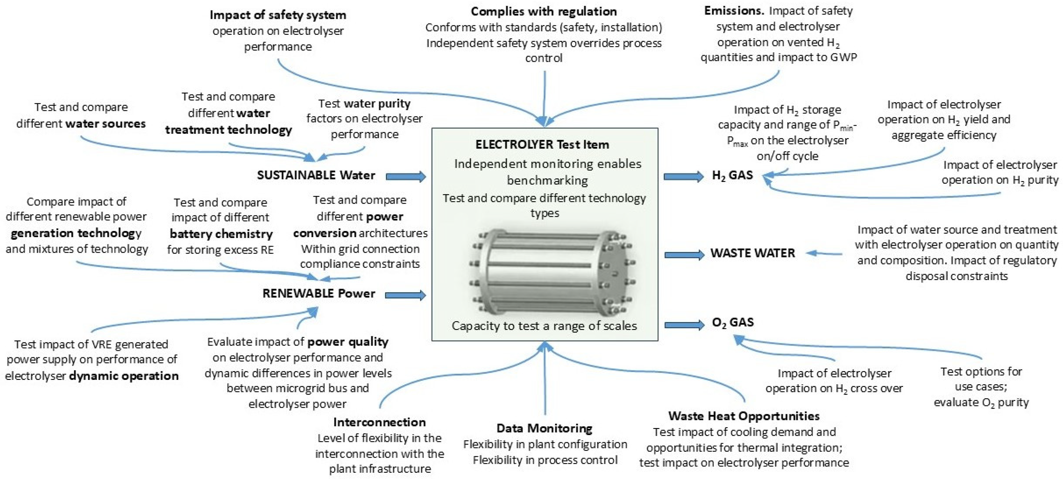
Figure 2.
Aerial view (facing southwest) of the H2Xport HRPH testbed (within the red border) located at QDAF Redlands Research Facility, 26-40 Delancey Street, Cleveland, QLD 4163 Australia (Coordinates: -27.526811, 153.249487). (A) Demountable/portable shed housing Enapter electrolysers (B) Container housing Nel electrolyser and Powercell fuel cell (C) Container housing membrane distillation equipment (D) Shed housing batteries, switchboard and IT equipment, with rooftop SiPV panels facing directly north; (E) Concentrated (E1) and single-axis (E2) PV systems for solar power generation.
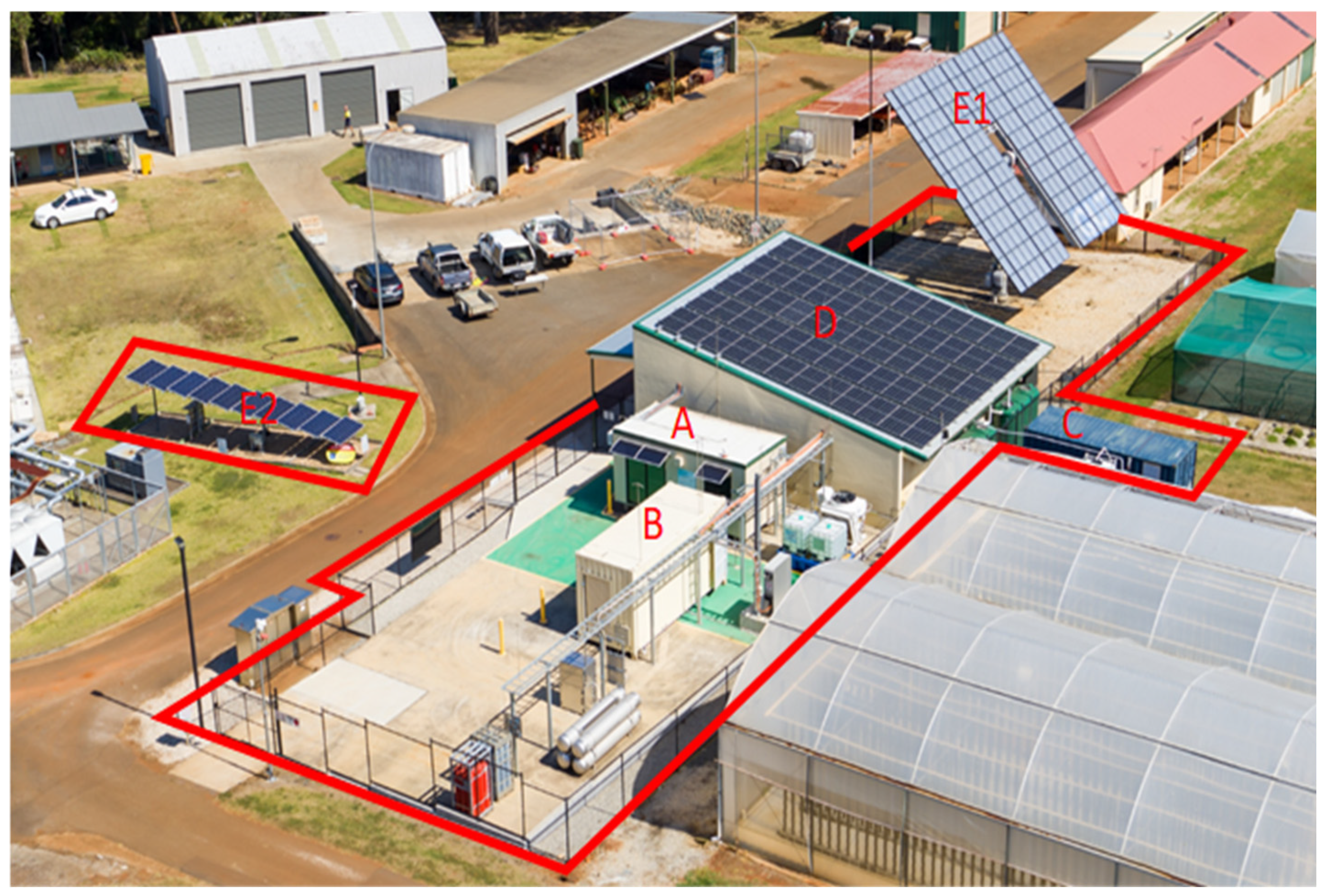
Figure 3.
Schematic of a flexible plug-and-play HRPH testbed at 50kW electrolysis scale including seawater and rainwater treatment to the required electrolysis standard. A grid connected testbed includes capability to benchmark three different solar and battery technologies, two different electrolyser technologies and a fuel cell for regenerative renewable power within a system architecture.
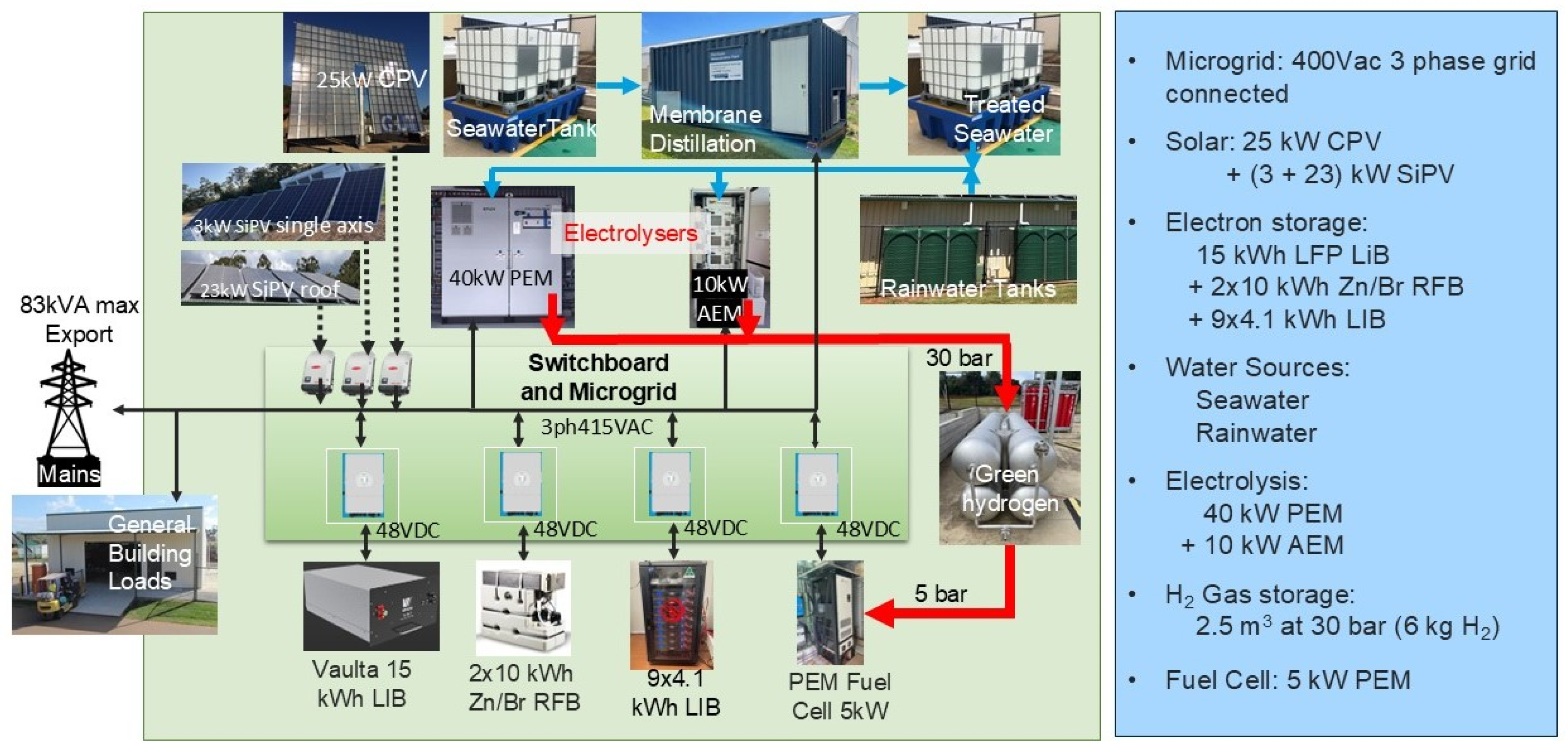
Figure 4.
Schematic of the water system in the H2Xport HRPH testbed utilising seawater as one viable sustainable source. Orange arrows are reject water streams. M are meters and R is a Davey Rainbank automatic splitter.
Figure 4.
Schematic of the water system in the H2Xport HRPH testbed utilising seawater as one viable sustainable source. Orange arrows are reject water streams. M are meters and R is a Davey Rainbank automatic splitter.
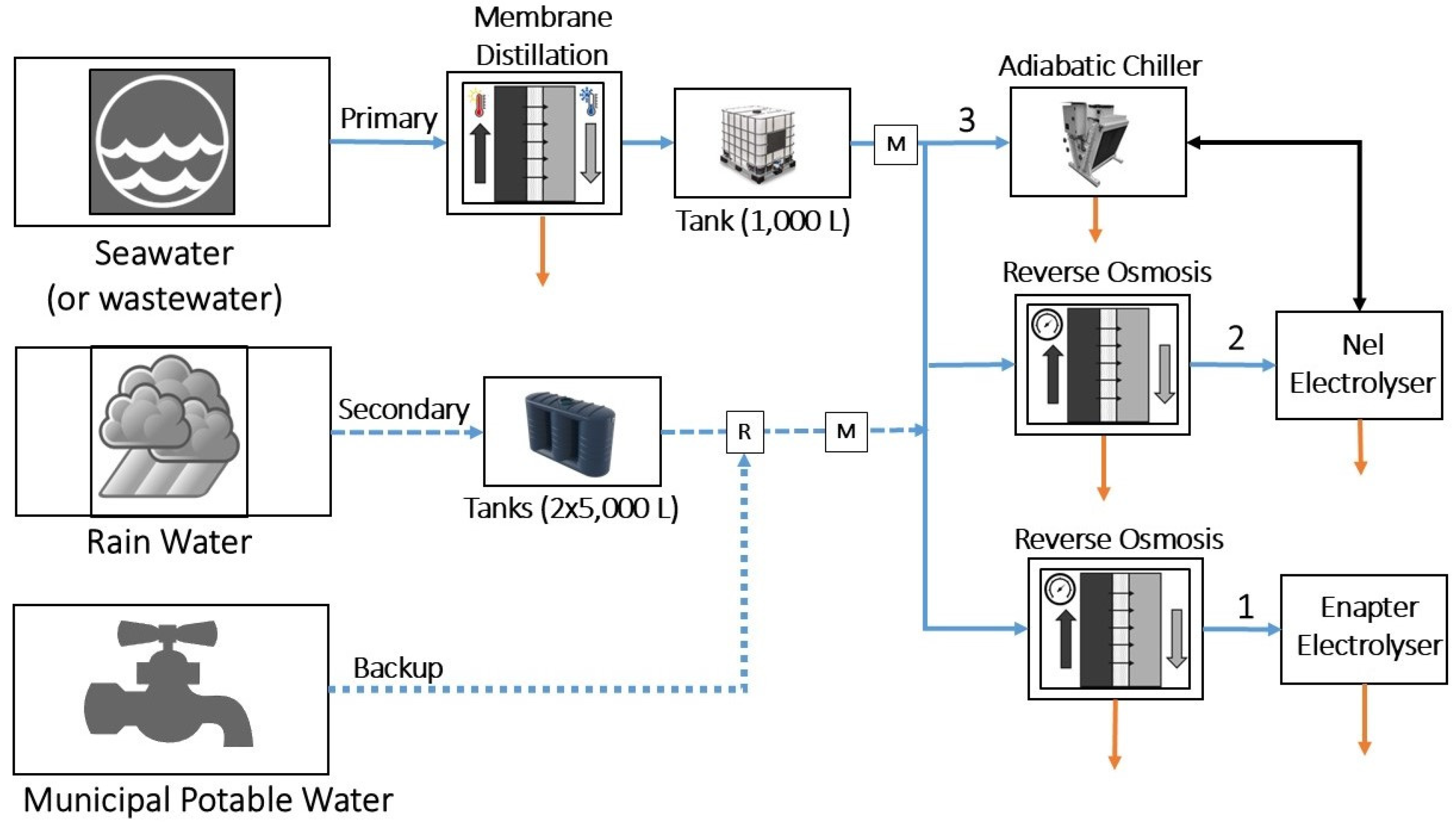
Figure 5.
Schematic of the hydrogen reticulation system not including vents, valves, oxygen and water streams. Panels 1 and 2 are electrolyser instrumentation panels for 30 bar output containing flow meters and pressure instrumentation. Moisture sensor (MS) is included in the container with the Nel electrolyser whereas Panel 1 includes a moisture sensor with the Enapter electrolyser. Panel 3 is the fuel cell instrumentation panel with gas regulation from 30 bar to 5 bar for input to the fuel cell. Panel 3 includes flow and pressure instrumentation. Panel 4 is the storage instrumentation panel at 30 bar and includes pressure and temperature instrumentation. All panels have nitrogen driven pneumatic control valves. Installed instruments are listed in Supplementary Table S2.
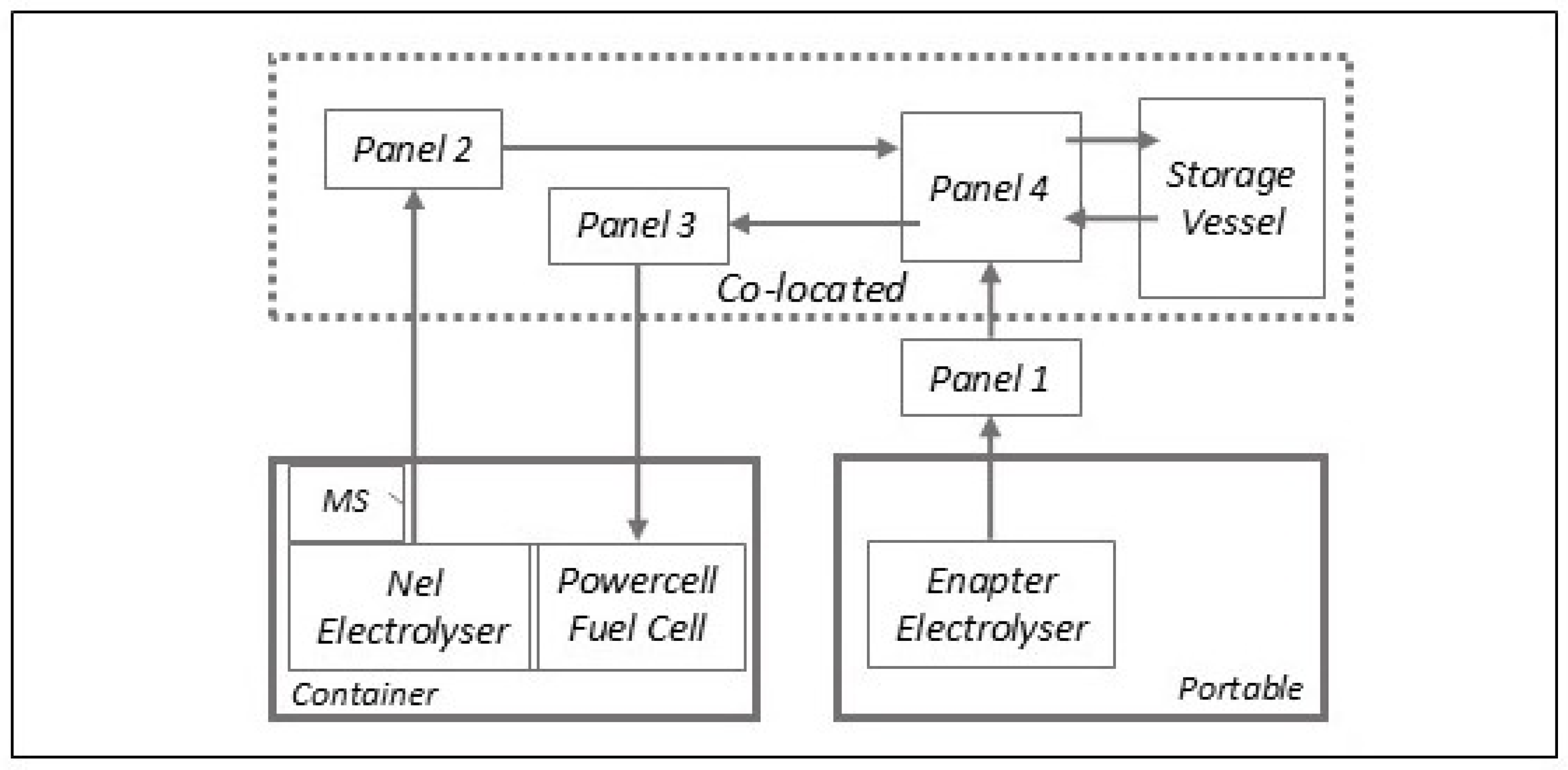
Figure 6.
Schematic of the integrated HRPH testbed system represented by three zones: electrons, electrochemical conversion and molecules. The xN multipliers indicate the number of different technologies connected. EES: Electron Energy Storage. HES: Hydrogen Energy Storage. TWS: Treated Water Storage. Orange arrows: power. Blue arrows: water. Green arrows: hydrogen. Black arrows: oxygen. For clarity, thermal integration options and the reject water and prospective water recycling streams are not included. Features greyed out are for future integration.
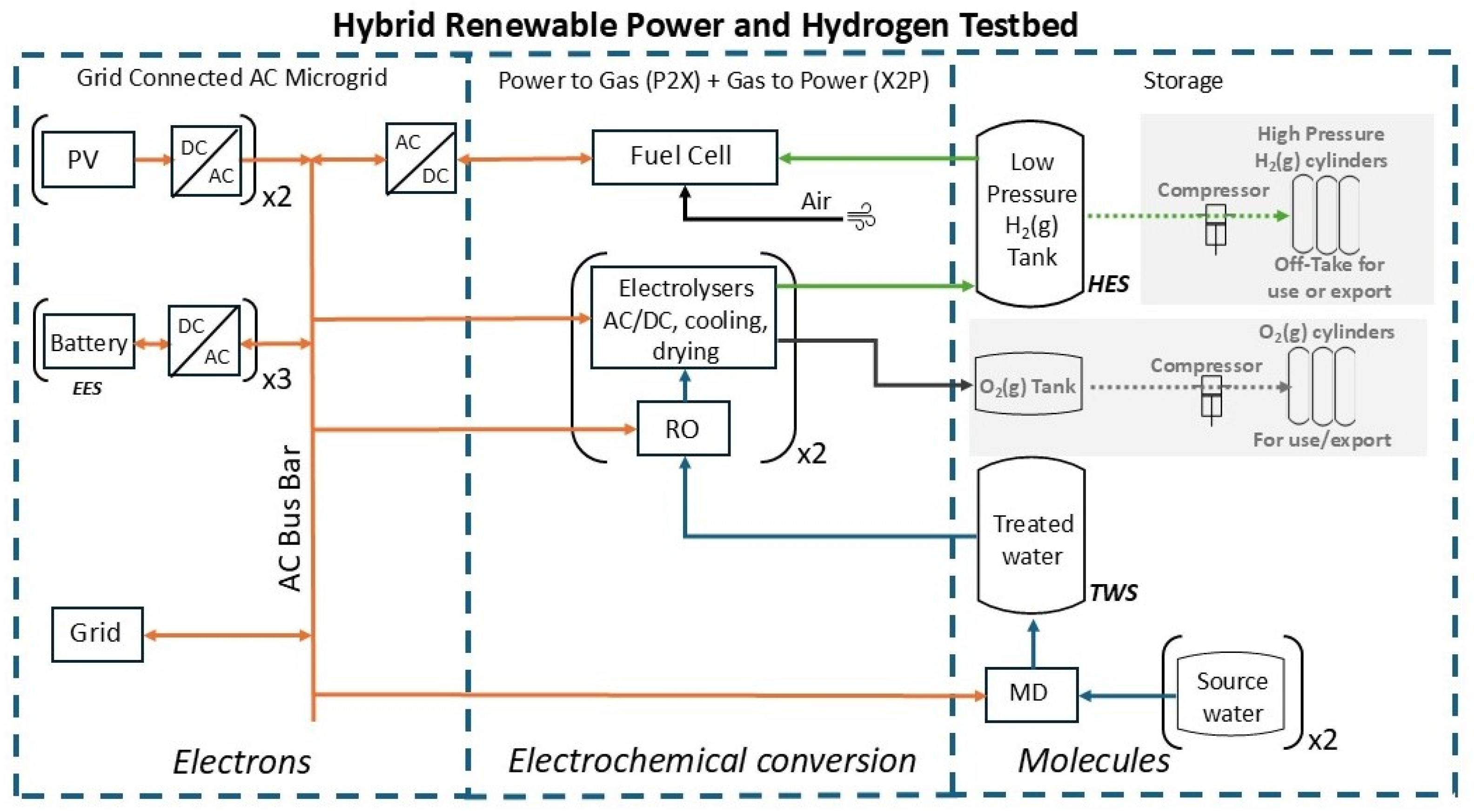
Figure 7.
Modelled output for 24 hr using one minute interval historical CPV and SiPV solar data on site as input to a Matlab model for an MVC of the H2Xport testbed. (A) Batteries discharging overnight (B) Batteries charging early morning then again when solar power is greater than electrolyser power (C) Excess solar power is exported to the grid (D) Electrolyser power follows the solar power up to maximum electrolyser power level. It is assumed that PEM electrolyser can rapidly change power level and follow solar power within one minute data intervals. (E) Solar power level is below electrolyser turn-down power level for hydrogen production; so the electrolyser is switched to standby power level with excess solar power exported to grid. Adapted from Figure 13 in Reference [25].
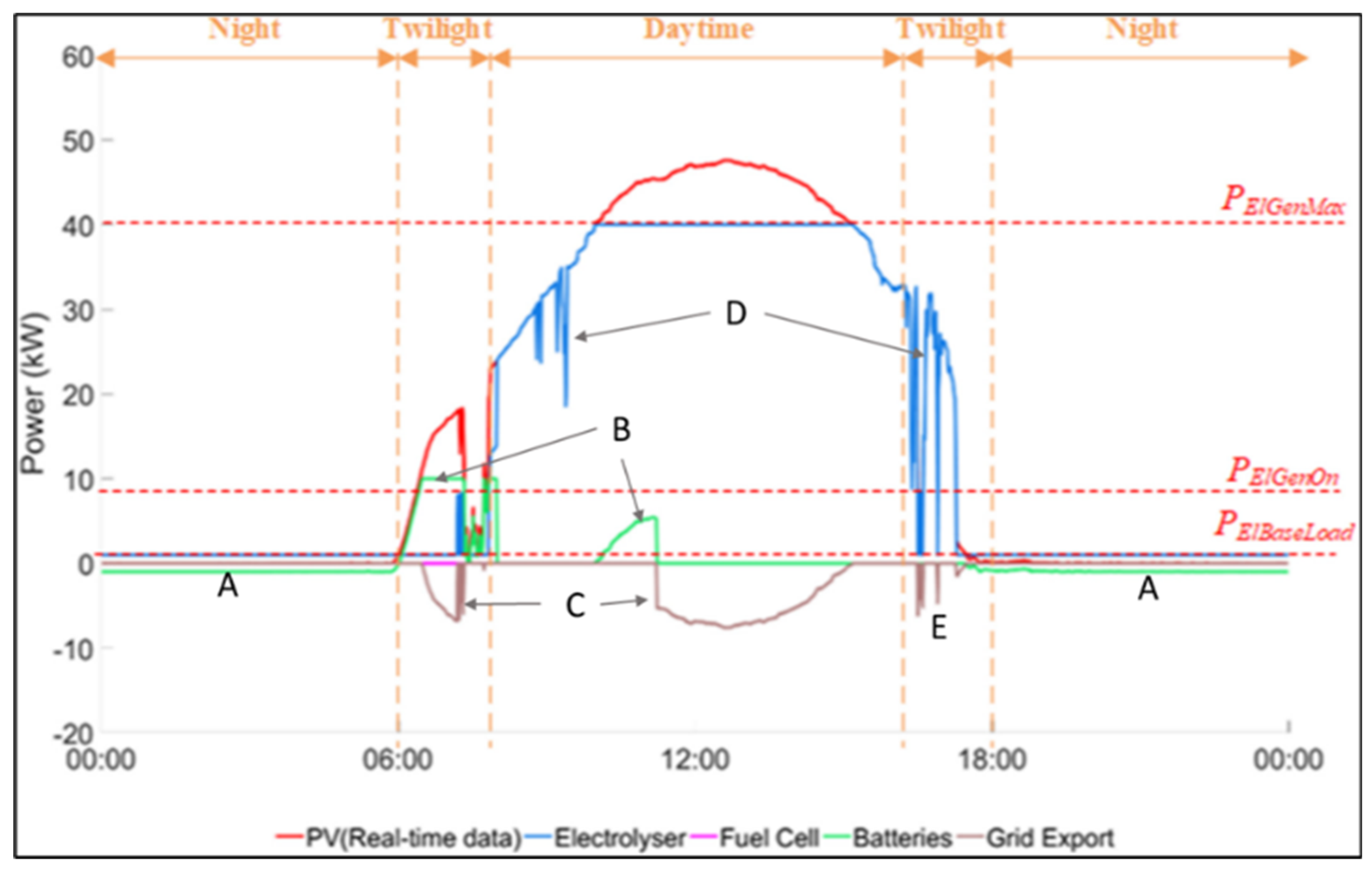

Table 1.
Description of technologies in the H2Xport HRPH Testbed.
| System Level | Technology | Equipment | Design Consideration | Constraints |
|---|---|---|---|---|
| Building | Australian Building Codes | Shed with fire wall. Shed auxiliaries: general lighting, fans, emergency lighting, IT equipment, GPOs. Greenbank LiB 5kW power for overnight power via Deye hybrid inverter. |
H2 Safety: Lightening protection, flame detection. Regulations: Building code, Fire wall. Safety Management Systems |
Site footprint determined by lease constraints, building size and area for locating hydrogen equipment and storage; critical for considering separation distances of hazardous area zones |
| Water Source | Tapwater and rainwater system | 10 kL rainwater tanks, pump, Davey Rainbank (water splitter). | Multiple water sources to be tested for impact on electrolyser performance. One of three sources in operation at any one time. Other water sources may be used in conjunction with water treatment technologies. | Site area limits size/quantity of tanks. Can “run dry” during drought periods. |
| Seawater | Seawater sourced from Moreton Bay coastline with freedom to remove. Stored on site in 1000L IBC + 3000L mixing/treatment tank with pumps. | Requires tankage from source ~100km from site. Pickup cannot be a marine park or protected marine environment | ||
| Water Treatment | Membrane Distillation | 20 ft container with MD unit plus vacuum and drive pumps, chemicals and cooling units. Multiple IBC’s and reticulation with instrumentation. Asahi Kasei membranes in completed project. | Multiple water treatment technologies can be tested for impact on electrolyser performance. Impact of water source with treatment on composition and quantity/re-use of wastewater. | Sized to specific H2O capacity of MD plant. Power demand from renewables requires a batch operation; treats onlywhen electrolysers are switched off or idle. Local codes constrain disposal of waste. Water purity imposed by OEM specification/warranty for electrolyser. |
| Reverse Osmosis | BWT Bonaqua 500 connect to Enapter Electrolyser. Purelab Chorus 2 RO deionisation unit with 20 L/hr output capacity connected to Nel Electrolyser. |
|||
| Solar Power | Concentrated PV | 25 kW CPV array. Prototype from Sumitomo Electric Industries1 installed 2017. Connected to microgrid via Fronius Inverter 27kW. | Compares impact of different renewable solar power generation technologies and mixtures of technology. Power output from CPV responds more rapidly than SiPV but provides almost zero power with cloud cover. | Scale of power fixed by CPV and land site. CPV output related to age. Power constrained by approved solar inverter. |
| Silicon PV | 3 kW single-axis ground mounted SiPV facing N; connect via Fronius Inverter 3kW. 23 kW on Shed rooftop facing N via Fronius 20 kW. | Scale of power is fixed by footprint and by approved solar inverters | ||
| Batteries | Redox Flow | Two ZBM3 Zn/Br Flow batteries from Redflow 3 kW/10 kWh each. 48Vdc connection to microgrid via Deye hybrid inverter. | Compares impact of different battery chemistries to manage excess RE and to compare charge/discharge performance of different LiB technologies. Batteries can be swapped for different products within constraints. | Constrained battery inverters fixed by compliance certificate; max power 8kW. Power/capacity constrained by OEM. |
| Lithium ion | LIB from Vaulta. 5 kW/15 kWh;. Nine Troppos LIBs from Red Earth each 3 kW/4kWh. 48Vdc connect via Deye hybrid inverter. | Multiple batteries of same type can be parallel connected to an inverter to increase capacity at same power. | ||
| Electrolysis | Anion Exchange Membrane | Enapter 4xEL4.0 AEM (total 10kW) air cooled housed in 20 ft portable shed with ventilation protection, dryer DRY01 and treatment WTM01 | Compares different electrolyser technology types albeit two electrolysers are at different scales (10kW and 40kW). Opportunity to compare degradation rates, wastewater compositions and water recycling. | For 100% renewable, scale of H2 production constrained by power of solar arrays. Operation constrained by working pressure of H2 storage; electrolyser with lower/higher H2 pressure requires a compressor, or de-rating, to match storage MWP. |
| Proton Exchange Membrane | Nel H6 40kW PEM liquid cooled housed in a 20 ft container with fuel cell and ventilation protection. External adiabatic chiller with 23.7 kWh cooling. | |||
| Hydrogen Storage | Compressed Hydrogen | Hydrogen storage unit as 2.5 m3 hydrogen tube with MWP 30 bar. Instrument panels and reticulated gas lines. | Single storage equipment available. No off-take in place for current installation. | Constrained by maximum working pressure (MWP) and fixed volume of registered pressure vessel. |
| Fuel Cell | Proton Exchange Membrane | Powercell PS5 system 5 kW with 48Vdc connection to microgrid via Deye hybrid inverter. Housed in 20 ft container with NEL Electrolyser. Liquid coolant plumbing connected to External Chiller. | Single storage equipment available. No off-take in place for current installation. | Constrained by maximum working pressure (MWP) and fixed volume of registered pressure vessel. |
Table 2.
Installation requirements for additional electrolysers in the H2Xport testbed.
| Sub-System | Connection Requirements for Prototype Electrolysers |
HRPH Testbed Constraints |
|---|---|---|
| Power connection | 3 phase 415Vac connection | Ranges from 0% to 100% mix of mains power with renewables. |
| Battery | Capability for electrolyser turn down to standby (no H2 production) overnight. | Max renewable power from batteries is 10kWac. |
| Water input | Max pressure 3 bar. Max electrolysis consumption 65 L/day. Purity specification to establish level of treatment. | Selectable mains, rainwater or treated seawater on site. RO unit before input to electrolyser. |
| Hydrogen output | 6 bar< Pressure < 30 bar. May require compressor. Purity: dried > 99.99%. Requires moisture sensor for monitoring. | Defined by low pressure tank; MWP fixed by tank design and validation; registered with local regulator. Min pressure and purity fixed by fuel cell specification. |
| Oxygen output | Separately vented or highly diluted if dispersed locally. Must have H2 level monitoring and automatic shutdown. | Testbed to meet WHS Act, Electrical Safety Act, and Petroleum and Gas Act. |
| Nitrogen | Optional. However, bulk N2 gas useful for commissioning/purging of gas reticulation system. | Available 24/7 for testbed pneumatic control valves (single cylinder). Bulk N2 can be added if required 24/7. |
| Cooling | Liquid/Air cooling integrated and supplied with electrolyser on installation. | HRPH testbed does not have common use cooling equipment/reticulation. |
| Electrical Earthing | All metal components and containers at equipotential with ground points to connect to testbed ground points. | Equipotential grounding point in slab earthing ring available |
| Emergency electrical shutdown (ESD) | Protection by ventilation monitoring using intrinsically safe devices connected to testbed ESD. H2 vent valves in electrolysers fail open; H2 is vented on power failure. | Power connections with a relay to automatically shut power to electrolyser if testbed ESD is activated |
| Control systems | In-built safety monitoring and automatic shut-off system independent of electrolyser control systems. Warnings and alarms to connect to testbed data acquisition system. | HRPH testbed does not have feedback control to action warnings/alarms. Testbed monitors the electrolyser status and can activate testbed ESD. Feedback control is a useful future addition. |
| Hazardous area | HAZID, HAZOP, Risk Assessment. Hazardous Area certificate; protection by ventilation if required. Conformance to standards. |
Testbed to meet WHS Act, Electrical Safety Act, and Petroleum and Gas Act. HRPH testbed hazardous area certificate must be updated when equipment is changed; requires an approved HA audit before powering new electrolyser connections. |
Disclaimer/Publisher’s Note: The statements, opinions and data contained in all publications are solely those of the individual author(s) and contributor(s) and not of MDPI and/or the editor(s). MDPI and/or the editor(s) disclaim responsibility for any injury to people or property resulting from any ideas, methods, instructions or products referred to in the content. |
© 2024 by the authors. Licensee MDPI, Basel, Switzerland. This article is an open access article distributed under the terms and conditions of the Creative Commons Attribution (CC BY) license (http://creativecommons.org/licenses/by/4.0/).
Copyright: This open access article is published under a Creative Commons CC BY 4.0 license, which permit the free download, distribution, and reuse, provided that the author and preprint are cited in any reuse.


