
Submitted:
02 December 2024
Posted:
03 December 2024
You are already at the latest version
Abstract
In this study, micro-scale numerical simulations were performed to evaluate the residual strength of carbon fiber reinforced plastics (CFRP) subjected to cyclic transverse and out-of-plane shear loading fatigue. The simulations utilized a finite element method incorporating an entropy-based damage criterion for the matrix resin. This method aimed to link entropy generation to strength degradation, with the parameter α_o (s)determined as a function of entropy. Cyclic tensile and shear analyses were conducted to correlate residual strength with entropy accumulation, establishing a linear relationship for α_o (s). The results demonstrated meso-scale strength degradation based on micro-scale numerical simulations. Material constants for the epoxy resin matrix were determined through creep and tensile tests, and a generalized Maxwell model with 15 elements was used to represent the viscoelastic behavior. Numerical simulations employed the Abaqus/Standard 2020 software, with the epoxy resin matrix behavior implemented via a UMAT subroutine. The analysis revealed a linear relationship between entropy and residual strength for both cyclic tensile and out-of-plane shear loading. This approach enhances experimental insights with numerical predictions, offering a comprehensive understanding of CFRP strength degradation under fatigue loading.
Keywords:
CFRP
; residual strength
; FEM
; numerical simulation
1. Introduction
Carbon fiber reinforced polymers (CFRPs) are widely used in the aerospace industry due to their excellent mechanical properties. Understanding their durability under long-term use is crucial; however, the current research predominantly relies on experimental approaches, with few studies employing numerical methods to investigate the strength degradation behavior of CFRPs deeply [1,2,3,4,5,6,7,8,9,10,11,12,13,14,15,16,17,18].
Recently, entropy-based fracture criteria have been adopted for matrix resins, defining material failure as the critical value of entropy generation [19,20,21,22,23,24,25,26,27,28,29,30,31]. When a material is unused and undamaged, its molecular arrangement is orderly, resulting in low entropy. Upon loading, the orderly molecular structure partially collapses, leading to an increase in entropy. This collapse is equivalent to the material's inelastic deformation. Thus, with repeated loading, the molecular structure collapses, increasing entropy until it reaches a critical value, causing material failure. The amount of entropy generated at failure is inherent to the material, independent of geometric shape, stress level, and frequency. This allows for the assessment of irreversible cumulative damage, using entropy generation to clarify the degradation of properties and estimate the fatigue life and residual strength of structural materials under periodic loading. Deng et al. performed micro-scale simulations of repeated loading [32]. They used an entropy-based fracture criterion to estimate the fatigue life of CFRPs under multi-amplitude cyclic loading, developing a micro finite element model that separately considered the matrix resin and fibers. However, they focused only on the onset of failure and did not estimate the overall fatigue life of CFRP, failing to link entropy generation to the overall behavior of CFRP. Koyanagi et al. incorporated entropy into Hashin’s criteria, enabling the representation of strength degradation that traditional Hashin’s criteria could not, and conducted mesoscale simulations of cyclic loading [33]. They reproduced the occurrence of transverse cracks, showing stress level and frequency dependence on the number of cracks. However, the coefficient α linking entropy increase to strength degradation remained undetermined, preventing a correct association between entropy generation and strength degradation. If this coefficient α can be determined through micro-scale analysis, it would enable the integration of micro-scale and mesoscale analyses.
Additionally, composite materials like CFRPs have complex microstructures and anisotropic properties. To understand the material properties of the entire product, it is common to perform material tests as mentioned earlier, but the properties obtained from material tests reflect macro-structural characteristics, not micro-structural ones. Therefore, if multi-scale analysis, considering both micro-scale and meso-scale properties, becomes possible, material design can fully leverage the inherent properties of the materials.
In this study, we conducted creep tests on epoxy resin, which is widely used as the matrix resin for CFRP. Using a generalized Maxwell model with 15 elements as the viscoelastic model, we determined the material constants and the necessary constants for numerical simulations. To establish the relationship between entropy generation and the residual strength after cyclic loading, we performed analyses using Abaqus/Standard 2020, with the epoxy resin matrix behavior implemented via the Abaqus/Standard user subroutine UMAT. We carried out micro-scale repeated tensile and out-of-plane shear analyses incorporating an entropy-based damage criterion for the resin part of CFRP. As a result, we established a linear relationship between the strength of CFRP after fatigue loading and the overall entropy of CFRP.
2. Degradable Hashin’s Criteria
As previously mentioned, Koyanagi et al. introduced entropy into the Hashin’s failure criteria. Eq. 1 to 4 represent the failure criteria, Eq. 5 to 11 represent strength reduction, and Eq. 12 to 15 represent fracture energy reduction. ,,,, (= ), and are the tensile strength in the longitudinal direction, compressive strength in the longitudinal direction, tensile strength in the transverse direction, compressive strength in the transverse direction, longitudinal (in-plane) shear strength, and transverse shear strength, respectively. , and are the fracture toughness in longitudinal tension, longitudinal compression, transverse tension, and transverse compression, respectively. The four damage criteria – fiber tensile mode , fiber compressive mode , transverse tensile mode , and transverse compressive mode – are calculated using the degraded strengths. When any of these criteria are met (e≥1), it is judged that damage has occurred. The constants , and used in strength reduction and fracture energy reduction relate entropy to strength reduction and fracture energy reduction. Currently, these values are arbitrary constants as they have not yet been determined.
Therefore, We aim to apply the entropy damage criteria to the matrix resin of CFRPs and conduct numerical analyses at the microscale. By correlating the residual strength of CFRPs after fatigue loading with entropy generation and determining as a function of entropy, I intend to represent mesoscale strength degradation considering the results of microscale numerical simulations. In this study, tensile fatigue analysis and out-of-plane shear fatigue analysis were performed, and was determined.
3. Determination of Material Constants
The most commonly used resin in CFRP is epoxy resin; therefore, this study employed epoxy resin [23]. DGBEA 50 g and 4,4’-DDS 16.3 g were mixed to create test specimens with dimensions of 60 mm in length, 10 mm in width, and 3 mm in thickness. Creep tests were conducted under stresses of 10 MPa, 20 MPa, 30 MPa, and 40 MPa, at temperatures of 40°C, 50°C, 60°C, 70°C, and 80°C for each stress level, with each test lasting 1 hour. The performed creep test data were shifted using the Arrhenius-type temperature-time equivalence principle (Eq. 16). The parameters were set as .
Using creep compliance, a time-strain function was created and fitted to the creep test results. The creep compliance and strain function are shown in Eq. 17 and Eq. 18, respectively. The constants were determined as . The results above are shown in Figure 1. The creep test results shifted using the temperature-time equivalence principle are indicated by solid lines, and the strain function obtained through fitting is indicated by dashed lines.
The stress relaxation curve , which is necessary for determining the stiffness and viscosity coefficients of the matrix resin, was obtained by taking the inverse of , resulting in a master curve. Although this conversion requires a Laplace transform, numerical substitution and calculation showed that the values obtained by taking the inverse of were almost identical. Therefore, in this study, which deals with numerical calculations, they are considered equivalent. is shown in Eq. 19
Next, for the 15 Maxwell models depicted in Figure 4, the stiffness of each element was set to 220 MPa, and the viscosity coefficients were fitted (Figure 2). A strain of 0.1 was assumed. The equation used is shown in Eq. 20. The determined stiffness and viscosity coefficients of each Maxwell element are presented in Table 1.
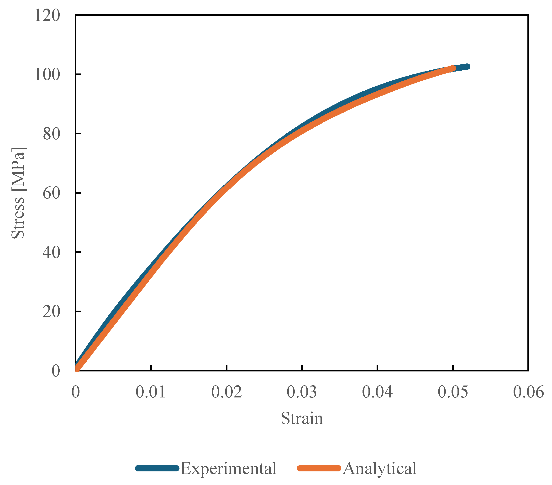
The determination of the non-linear coefficient, as shown in Eq. 22, was conducted. Using the same specimens as in the creep tests, a tensile test was performed at room temperature with a strain rate of 0.5% per second, and the numerical analysis results were fitted. It was determined that , and .
Figure 3.
Experimental and Analytical Stress-Strain curve for determining non-linear coefficient.
4. Numerical Procedures
4.1. Analysis Algorithm for the Matrix Resin
In this study, a generalized Maxwell model shown in Figure 4 was employed as the viscoelastic model, comprising 15 Maxwell elements. The material constants used were determined as previously described. Analyses were conducted using Abaqus/Standard 2020, and the analysis algorithm for the epoxy resin matrix was implemented using the Abaqus/Standard user subroutine UMAT. The UMAT computational flow was shown in Figure 5. First, the strain increment is taken as the viscoelastic strain increment, and a temporally stress increment is calculated. From this temporally stress increment, the temporally spring extension and the temporally stress increment of the Maxwell elements are determined, and the deformation of the dashpot is calculated. Using the temporally spring extension and temporally dashpot deformation, the extension of the spring is computed, and the stress increment for each Maxwell element is determined. By summing the stress increments of each Maxwell element, the total stress increment is obtained. Additionally, the dissipated energy is calculated from the dashpot deformation and stress, and the damage coefficient is determined and carried over to the next increment. The stress of each Maxwell element and the total stress are carried over to the next increment and used in the calculation of the nonlinear coefficients and the dashpot elongation. When the damage coefficient (D) reaches 0.25, the element is considered to have failed, and element deletion is performed. This ensures that the failed elements no longer carry any stress. For the damage coefficient (Eq. 25), following the simple tensile test by Kudo et al. [23], the fracture entropy was set to 20 .
4.2. Analysis Model and Conditions
For the CFRP model, a three-dimensional unit cell analysis model of CFRP, as shown in Figure 6, was utilized. The dimensions of the 3D unit cell were 39 μm × 39 μm × 0.3 μm. The carbon fibers had an elastic modulus of 14 GPa, a Poisson's ratio of 0.3, and a diameter of 6 μm, with 30 fibers included at a volume fraction of 56%. This study did not consider the fiber/matrix interface. The element type used was an 8-node brick element. The epoxy resin matrix was assumed to be a nonlinear viscoelastic material, following a constitutive equation that considers entropy damage. The analysis model applied periodic boundary conditions to all edges using the key degree of freedom method [3,8,12,34,35,36,37,38,39].
For the cyclic tensile analysis, as shown in Figure 7, Dummy-Y was subjected to repeated tensile loading in the Y-axis direction. Displacement control was used to apply strains of 0.1 %, 0.2 %, 0.3 %, 0.4 %, 0.5 %, 0.7 % and 0.8% for 5, 10, 20, 40, and 80 cycles. The average entropy increase of all elements at the end of each cycle was calculated, and after completing the cycles, tensile fracture was induced at a strain rate of 0.1 %/s to determine the residual strength as the maximum stress at fracture.
For the cyclic out-of-plane shear analysis, as shown in Figure 8, the central node was pinned, and a Dummy-X was subjected to repeated shear loading in the Z-direction. Displacement control was used to apply strains of 0.1 %, 0.2 %, 0.3 %, 0.4 %, 0.5 %, 0.6 %, 0.7% and 0.8% for 5, 10, 20, 40, and 80 cycles. The average entropy increase of all elements at the end of each cycle was calculated, and after completing the cycles, tensile fracture was induced at a strain rate of 0.1 %/s to determine the residual strength as the maximum stress at fracture.
5. Results
As an example of the analysis results, Figure 9 shows the damage state after applying repeated tensile loading at a strain of 0.8% for 10 cycles, 20 cycles, 40 cycles, and 80 cycles. The maximum damage value is set to D = 0.25, indicating that the damage coefficient increases from blue to red. Similarly, Figure 10 shows the damage state after applying repeated out-of-plane shear loading at a strain of 0.8% for 10 cycles, 20 cycles, 40 cycles, and 80 cycles. Again, the maximum damage value is set to D = 0.06, indicating that the damage coefficient increases from blue to red. In both analyses, as the number of load cycles increases, the damage also increases.
The relationship between residual strength and entropy derived from cyclic tensile and cyclic out-of-plane shear analyses was fitted with as a linear function and is shown in Figure 11 for cyclic tensile analysis and Figure 12 for cyclic out-of-plane shear analysis. In both the cyclic tensile analysis and the cyclic out-of-plane shear analysis, it was found that an increase in entropy leads to a decrease in residual strength. The determined for each analysis are presented in Eq. 26 and Eq. 27. The residual strength was standardized.
6. Conclusions
In this study, we conducted micro-scale numerical simulations to evaluate the residual strength of CFRP subjected to cyclic transverse and out-of-plane shear loading fatigue using a finite element method. By incorporating an entropy-based damage criterion for the matrix resin, we established a linear relationship, which is in Hashin’s’s criterion, between entropy accumulation and strength degradation. The simulations demonstrated that increased entropy, resulting from cyclic loading, directly correlates with decreased residual strength in CFRP. Material constants for the epoxy resin matrix were determined through creep and tensile tests, and a generalized Maxwell model was used to represent viscoelastic behavior. The Abaqus/Standard 2020 software facilitated these analyses with the epoxy resin matrix behavior implemented via a UMAT subroutine. The linear relationship between entropy and residual strength was validated for both cyclic tensile and shear loading conditions. This suggests that using entropy generation allows for a comprehensive assessment of damage under various loading histories. This approach enhances experimental insights with numerical predictions, offering a comprehensive understanding of CFRP strength degradation under fatigue loading. The findings underscore the potential of micro-scale numerical simulations to accurately predict meso-scale strength degradation, thus contributing significantly to the material design and durability assessment of CFRP in practical applications.
Acknowledgments
The work was supported by the JST-Mirai Program [221036344].
References
- Banks-Sills Leslie, Choron Tomer, Simon Ido, Effect of number of fatigue cycles on fatigue data: CFRP (prepreg and wet-layup).
- Fatigue and Fracture of Engineering Materials and Structures 2024, 47, 833–848.
- Yuki, N.; Atsushi, H.; Hiroyuki, K. Evaluation of matrix crack growth in interlaminar toughened quasi-isotropic carbon-fiber reinforced plastic laminates up to the very-high cycle regime by ultrasonic fatigue testing. Composites Science and Technology 2024, 253, 110623. [Google Scholar]
- Kumar, S.K.; Nisha, S. Fatigue behavior of symmetric and asymmetric carbon and basalt fiber-reinforced polymer composites in transverse loading. Journal of the Brazilian Society of Mechanical Sciences and Engineering 2024, 46, 245. [Google Scholar]
- Lei, Z.; Pan, R.; Sun, W.; Dong, Y.; Wan, Y.; Yin, B. Fatigue damage mechanisms and evolution of residual tensile strength in CFRP Composites: Stacking sequence effect. Composite Structures 2024, 330, 117818. [Google Scholar] [CrossRef]
- Lars, G.; Selim, M.; Jan, K.; Verena, W.; Peter, J.; Frank, W. Fatigue performance of laser cut carbon fiber-reinforced epoxy and polyamide 6 considering specimen width. Materialpruefung/Materials Testing 2023, 65, 1645–1656. [Google Scholar]
- Frik, M.; Benkedjouh, T.; Essaidi, A.; Bouzar Boumediene, F. Advancing Damage Assessment of CFRP-Composite through BILSTM and Hilbert Upper Envelope Analysi. Russian Journal of Nondestructive Testing 2023, 59, 1241–1258. [Google Scholar] [CrossRef]
- Jia, Z.; Garnier, C.; Pastor, M.-L.; Rousseau, J.; Gong, X. Experimental investigation of impacted multidirectional laminates under compressive static and cyclic loading. Composite Structures 2023, 322, 117335. [Google Scholar] [CrossRef]
- Jia, Z.; Pastor, M.-L.; Garnier, C.; Gong, X. Fatigue life determination based on infrared thermographic data for Multi-Directional (MD) CFRP composite laminates. Composite Structures 2023, 319, 117202. [Google Scholar] [CrossRef]
- Morgado, G.F.D.M.; Montagna, L.S.; Gouvêa, R.F.; Guimarães, A.; Passador, F.R.; Rezende, M.C. Fatigue and durability assessment of PA6-based carbon fiber composites for lightweight applications. Journal of Composite Materials 2023, 57, 4227–4238. [Google Scholar] [CrossRef]
- Nishi, Y.; Itoh, S.; Hosoi, A.; Kawada, H. Stress and energy release rate analysis of cross-ply carbon fiber-reinforced plastic laminate with transverse cracks subjected to ultrasonic vibration using a variational approach, (2024) Advanced Composite Materials.
- Wu, Y.; Gong, Y.; Tian, D.; Zou, L.; Zhao, L.; Zhang, J.; Hu, N. Influence of curing pressure on the mode I static and fatigue delamination growth behavior of CFRP laminates. Composite Structures 2023, 322, 117345. [Google Scholar] [CrossRef]
- Vishe, N.J.; Mulani, S.B.; Roy, S. Repeatable self-healing of composite's fatigue delamination. Composite Structures 2023, 311, 116846. [Google Scholar] [CrossRef]
- Li, X.; Benedictus, R.; Zarouchas, D. Analysis of Stochastic Matrix Crack Evolution in CFRP Cross-Ply Laminates under Fatigue Loading. Eng. Fail. Anal. 2023, 150, 107277. [Google Scholar] [CrossRef]
- Aoki, R.; Higuchi, R.; Yokozeki, T. Progressive damage and residual strength of open-hole thin-ply CFRP laminates under tensile fatigue loading. Compos. Struct. 2023, 314, 116973. [Google Scholar] [CrossRef]
- Mrzljak, S.; Zanghellini, B.; Gerdes, L.; Helwing, R.; Schuller, R.; Sinn, G.; Lichtenegger, H.; Walther, F.; Rennhofer, H. Effect of carbon nanofibre orientation on fatigue properties of carbon fibre-reinforced polymers. J. Compos. Mater. 2023, 57, 1149–1164. [Google Scholar] [CrossRef]
- Guo, Y.-E.; Shang, D.-G.; Zuo, L.-X.; Qu, L.-F.; Cai, D.; Jin, T.; Li, D.-H. Fatigue life prediction considering strength contribution of fibre layers with different orientations for CFRP laminates at high temperature. Composite Structures 2023, 306, 116604. [Google Scholar] [CrossRef]
- Koyanagi, J.; Nakada, M.; Miyano, Y. Tensile strength at elevated temperature and its applicability as an accelerated testing methodology for unidirectional composites. Mech. Time-Dependent Mater. 2011, 16, 19–30. [Google Scholar] [CrossRef]
- Arao, Y.; Koyanagi, J.; Utsunomiya, S.; Takeda, S.; Kawada, H. Analysis of time-dependent deformation of a CFRP mirror under hot and humid environment. Mechanics of Time-Dependent Materials 2009, 13, 183–197. [Google Scholar] [CrossRef]
- Sakai, T.; Oya, Y.; Koyanagi, J. Evaluation of Volumetric Strain on Polyamide 6 by Thermodynamic Entropy Generation. Exp. Mech. 2023, 64, 105–111. [Google Scholar] [CrossRef]
- Li, Y.; Deng, H.; Takamura, M.; Koyanagi, J. Durability Analysis of CFRP Adhesive Joints: A Study Based on Entropy Damage Modeling Using FEM. Materials 2023, 16, 6821. [Google Scholar] [CrossRef]
- Deng, H.; Toda, K.; Sato, M.; Koyanagi, J. Micro-Scale Numerical Simulation of Fatigue Failure for CFRP Subjected to Multiple-Amplitude Cyclic Loadings Based on Entropy Damage Criterion. Materials 2023, 16, 6120. [Google Scholar] [CrossRef]
- Kudo, N.; Fujita, R.; Oya, Y.; Sakai, T.; Nagano, H.; Koyanagi, J. Identification of invisible fatigue damage of thermosetting epoxy resin by non-destructive thermal measurement using entropy generation. Adv. Compos. Mater. 2023, 33, 233–249. [Google Scholar] [CrossRef]
- Deng, H.; Mochizuki, A.; Fikry, M.; Abe, S.; Ogihara, S.; Koyanagi, J. Numerical and Experimental Studies for Fatigue Damage Accumulation of CFRP Cross-Ply Laminates Based on Entropy Failure Criterion. Materials 2022, 16, 388. [Google Scholar] [CrossRef] [PubMed]
- Yamada, N.; Oya, Y.; Kato, N.; Mori, K.; Koyanagi, J. A Molecular Dynamics Simulation for Thermal Activation Process in Covalent Bond Dissociation of a Crosslinked Thermosetting Polymer. Molecules 2023, 28, 2736. [Google Scholar] [CrossRef] [PubMed]
- Kagawa, H.; Umezu, Y.; Sakaue, K.; Koyanagi, J. Numerical simulation for the tensile failure of randomly oriented short fiber reinforced plastics based on a viscoelastic entropy damage criterion. Compos. Part C 2022, 10, 100342. [Google Scholar] [CrossRef]
- Koyanagi, J.; Mochizuki, A.; Higuchi, R.; Tan, V.; Tay, T. Finite element model for simulating entropy-based strength-degradation of carbon-fiber-reinforced plastics subjected to cyclic loadings. Int. J. Fatigue 2022, 165, 107204. [Google Scholar] [CrossRef]
- Sakai, T.; Takase, N.; Oya, Y.; Koyanagi, J. A Possibility for Quantitative Detection of Mechanically-Induced Invisible Damage by Thermal Property Measurement via Entropy Generation for a Polymer Material. Materials 2022, 15, 737. [Google Scholar] [CrossRef]
- Iwamoto, S.; Oya, Y.; Koyanagi, J. Evaluation of Microscopic Damage of PEEK Polymers under Cyclic Loadings Using Molecular Dynamics Simulations. Polymers 2022, 14, 4955. [Google Scholar] [CrossRef]
- Takase, N.; Koyanagi, J.; Mori, K.; Sakai, T. Molecular Dynamics Simulation for Evaluating Fracture Entropy of a Polymer Material under Various Combined Stress States. Materials 2021, 14, 1884. [Google Scholar] [CrossRef]
- Sato, M.; Hasegawa, K.; Koyanagi, J.; Higuchi, R.; Ishida, Y. Residual strength prediction for unidirectional CFRP using a nonlinear viscoelastic constitutive equation considering entropy damage. 2020, 141, 106178. [CrossRef]
- Deng, H.; Toda, K.; Sato, M.; Koyanagi, J. Micro-Scale Numerical Simulation of Fatigue Failure for CFRP Subjected to Multiple-Amplitude Cyclic Loadings Based on Entropy Damage Criterion. Materials 2023, 16, 6120. [Google Scholar] [CrossRef]
- Koyanagi, J.; Mochizuki, A.; Higuchi, R.; Tan, V.; Tay, T. Finite element model for simulating entropy-based strength-degradation of carbon-fiber-reinforced plastics subjected to cyclic loadings. Int. J. Fatigue 2022, 165, 107204. [Google Scholar] [CrossRef]
- Li, S.; Warrior, N.; Zou, Z.; Almaskari, F. Composites : Part A A unit cell for FE analysis of materialswith the microstructure of a staggered pattern 2011, 42, 801–11.
- Melro, A.; Camanho, P.; Pires, F.A.; Pinho, S. Micromechanical analysis of polymer composites reinforced by unidirectional fibres: Part II – Micromechanical analyses. Int J Solids Struct 2013, 50, 1906–1915. [Google Scholar] [CrossRef]
- Li, S.; Jeanmeure, L.F.C.; Pan, Q. A composite material characterisation tool: UnitCells. J. Eng. Math. 2015, 95, 279–293. [Google Scholar] [CrossRef]
- Higuchi, R.; Yokozeki, T.; Nagashima, T.; Aoki, T. Evaluation of mechanical properties of noncircular carbon fiber reinforced plastics by using XFEM-based computational micromechanics. Compos. Part A: Appl. Sci. Manuf. 2019, 126, 105556. [Google Scholar] [CrossRef]
- Sawamura, Y.; Yamazaki, Y.; Yoneyama, S.; Koyanagi, J. Multi-scale numerical simulation of impact failure for cylindrical CFRP. Adv. Compos. Mater. 2020, 30, 19–38. [Google Scholar] [CrossRef]
- Sato, M.; Shirai, S.; Koyanagi, J.; Ishida, Y.; Kogo, Y. Numerical simulation for strain rate and temperature dependence of transverse tensile failure of unidirectional CFRP. Journal of Composite Materials 2019, 53, 4305–4312. [Google Scholar] [CrossRef]
- Yoshida, H.; Deng, H.; Koyanagi, J. Enhanced Estimation of Axial Compressive Strength for CFRP Based on Microscale Numerical Simulation and the Response Surface Method. Materials 2024, 17, 478. [Google Scholar] [CrossRef]
Figure 1.
fitted to the result of creep test.
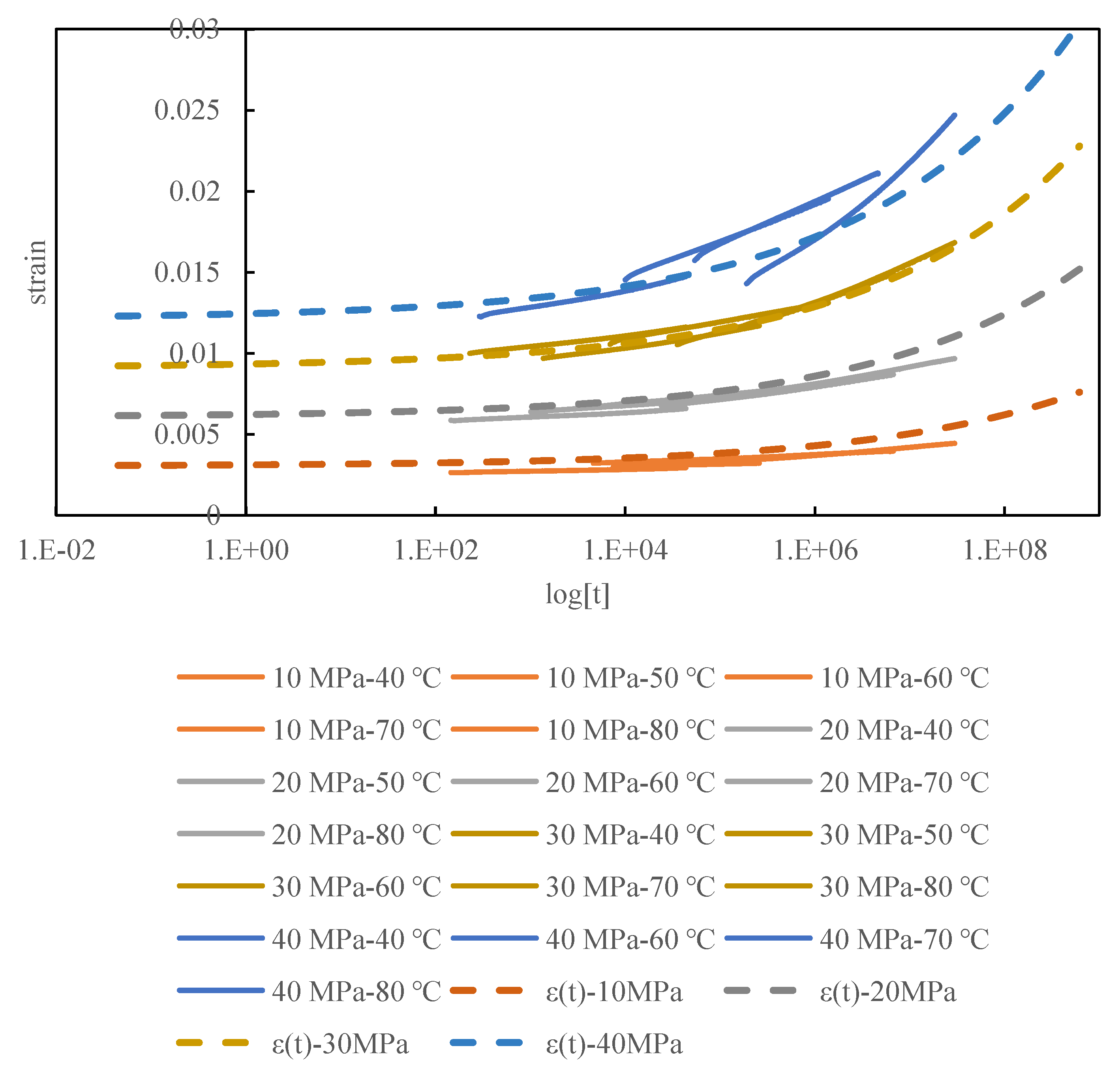
Figure 2.
Analytical curve fitted to Master curve.
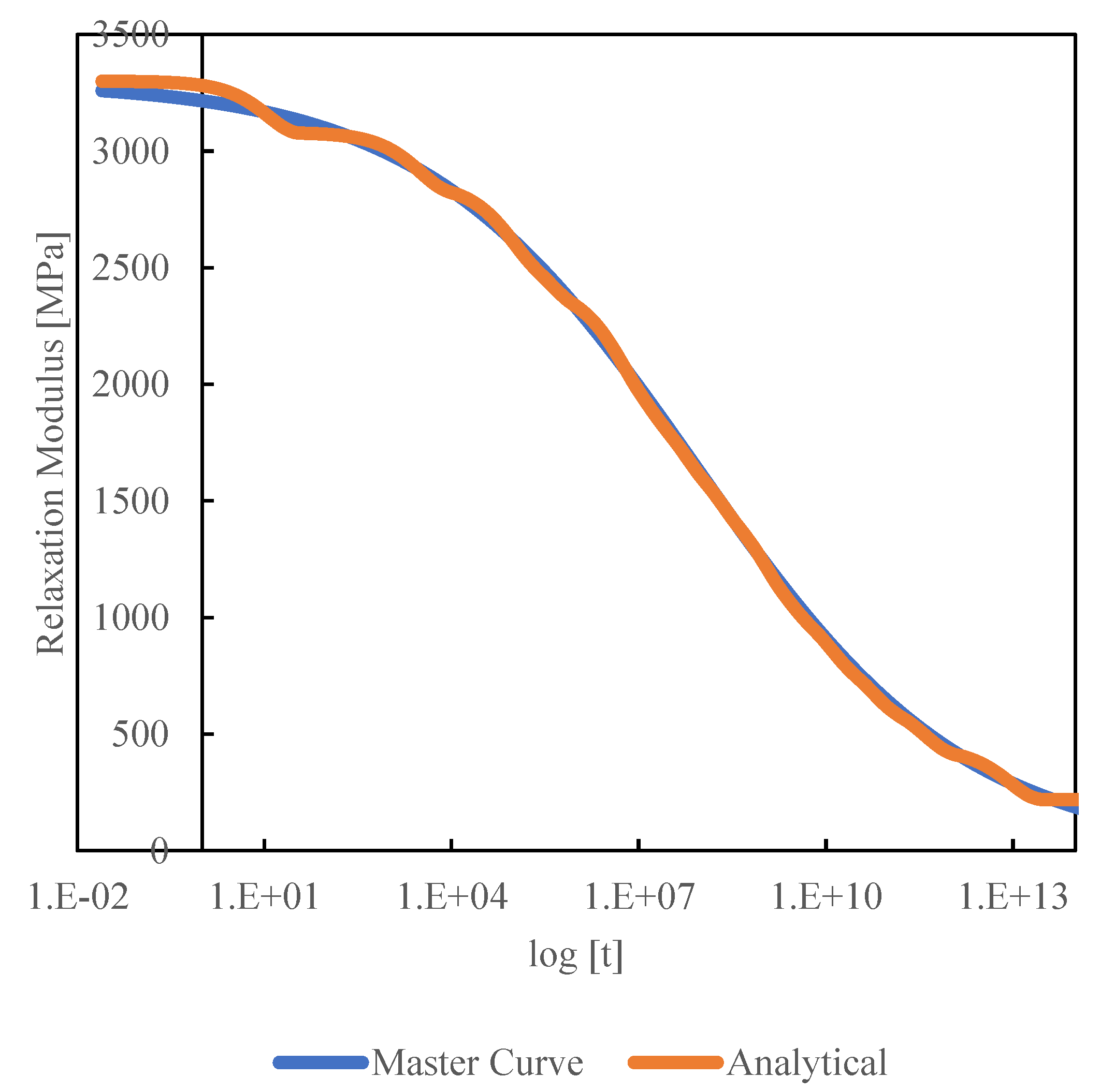
Figure 4.
Generalized Maxwell model for analyzing viscoelastic behavior.
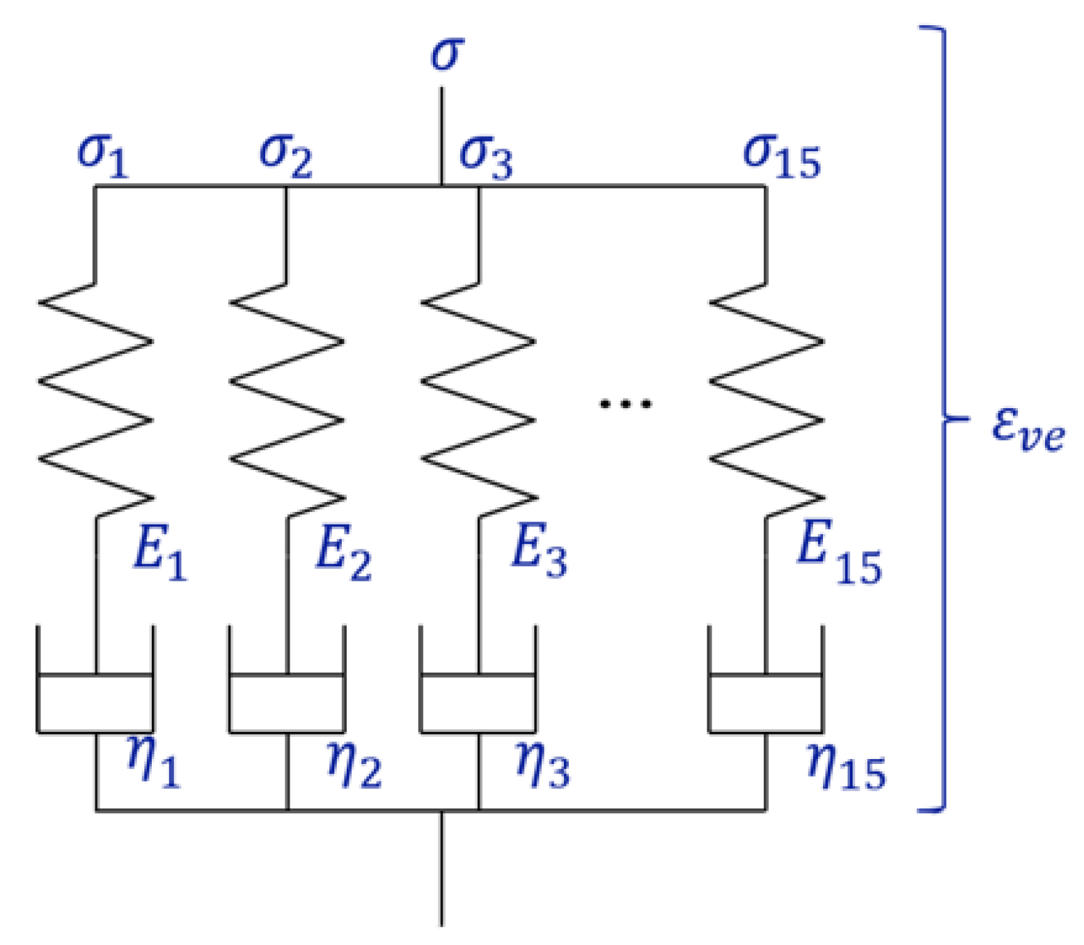
Figure 5.
Overall flowchart for updating stress.
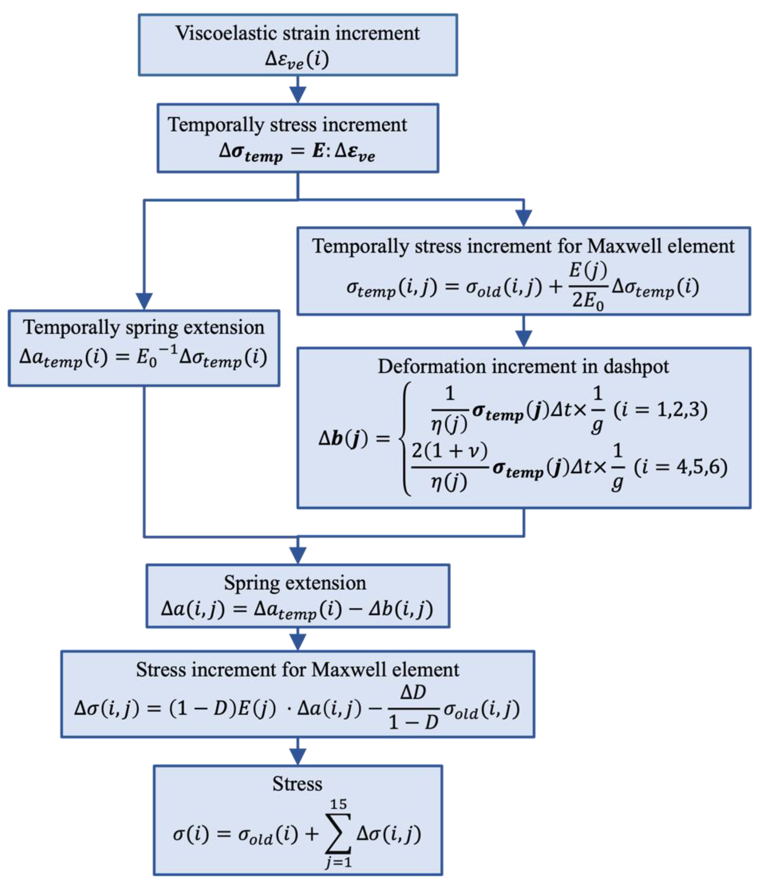
Figure 6.
Finite element model of CFRP.
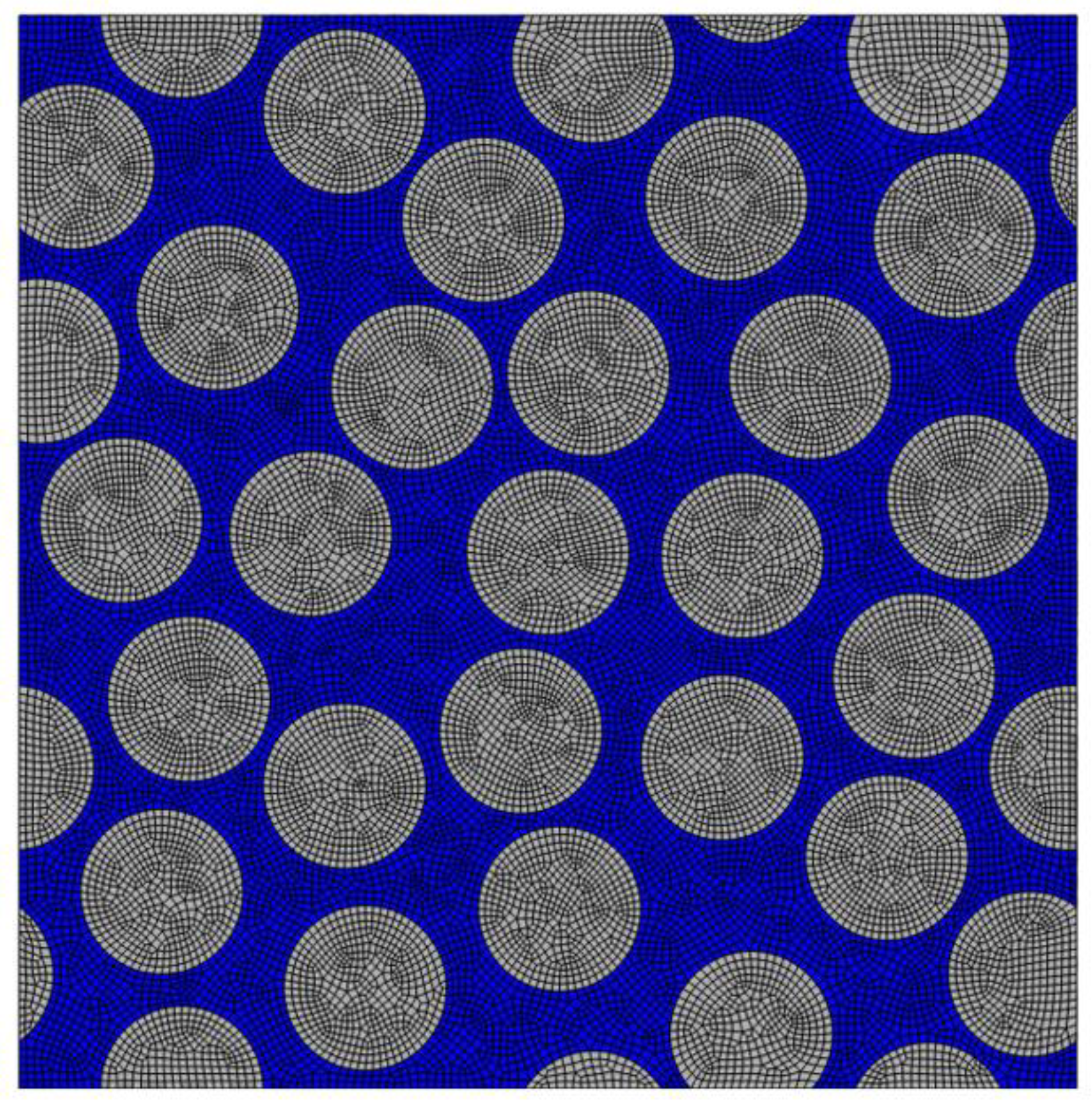
Figure 7.
Finite element model for analyzing cyclic tensile.
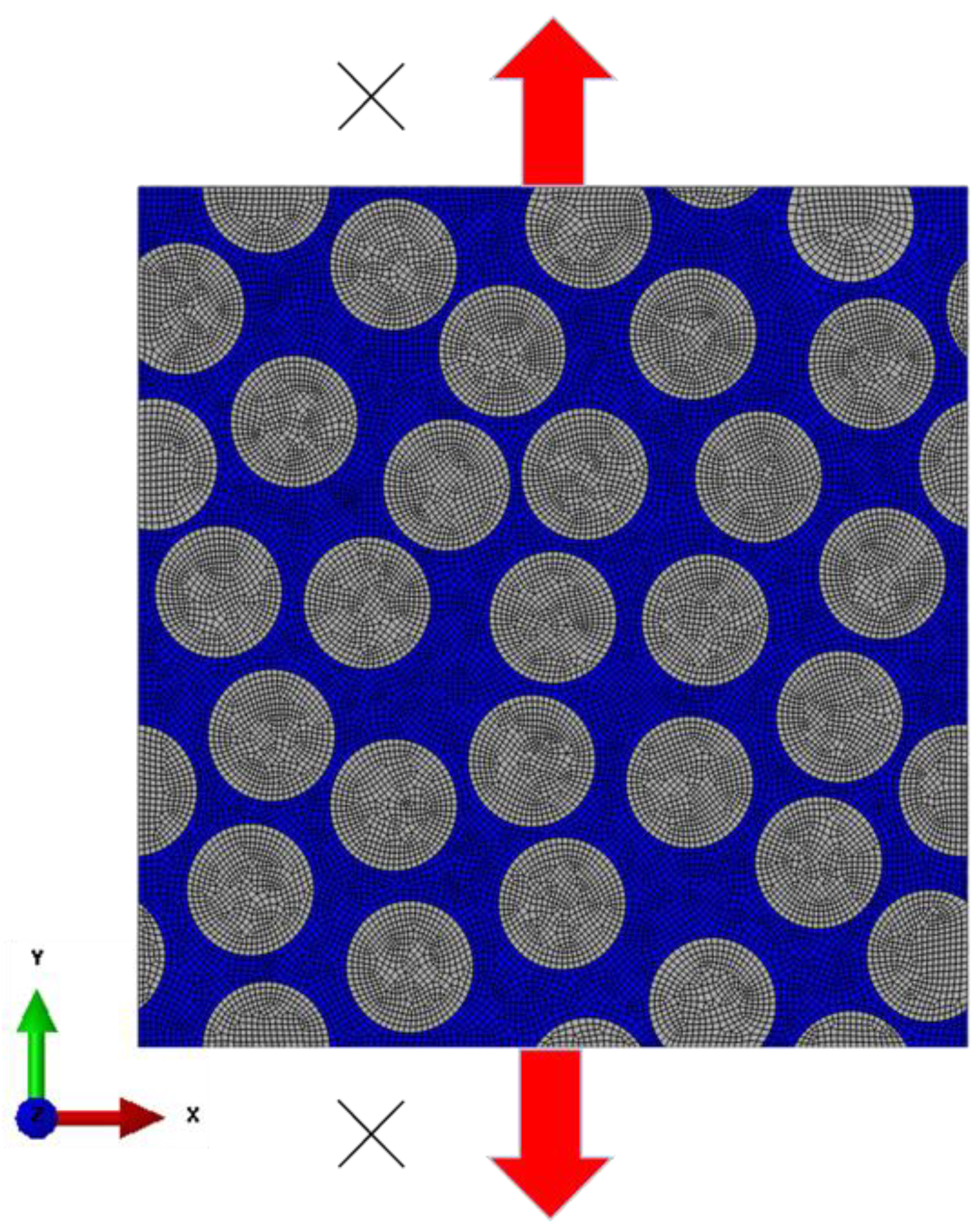
Figure 8.
Finite element model for analyzing cyclic-out-of-plane shear.
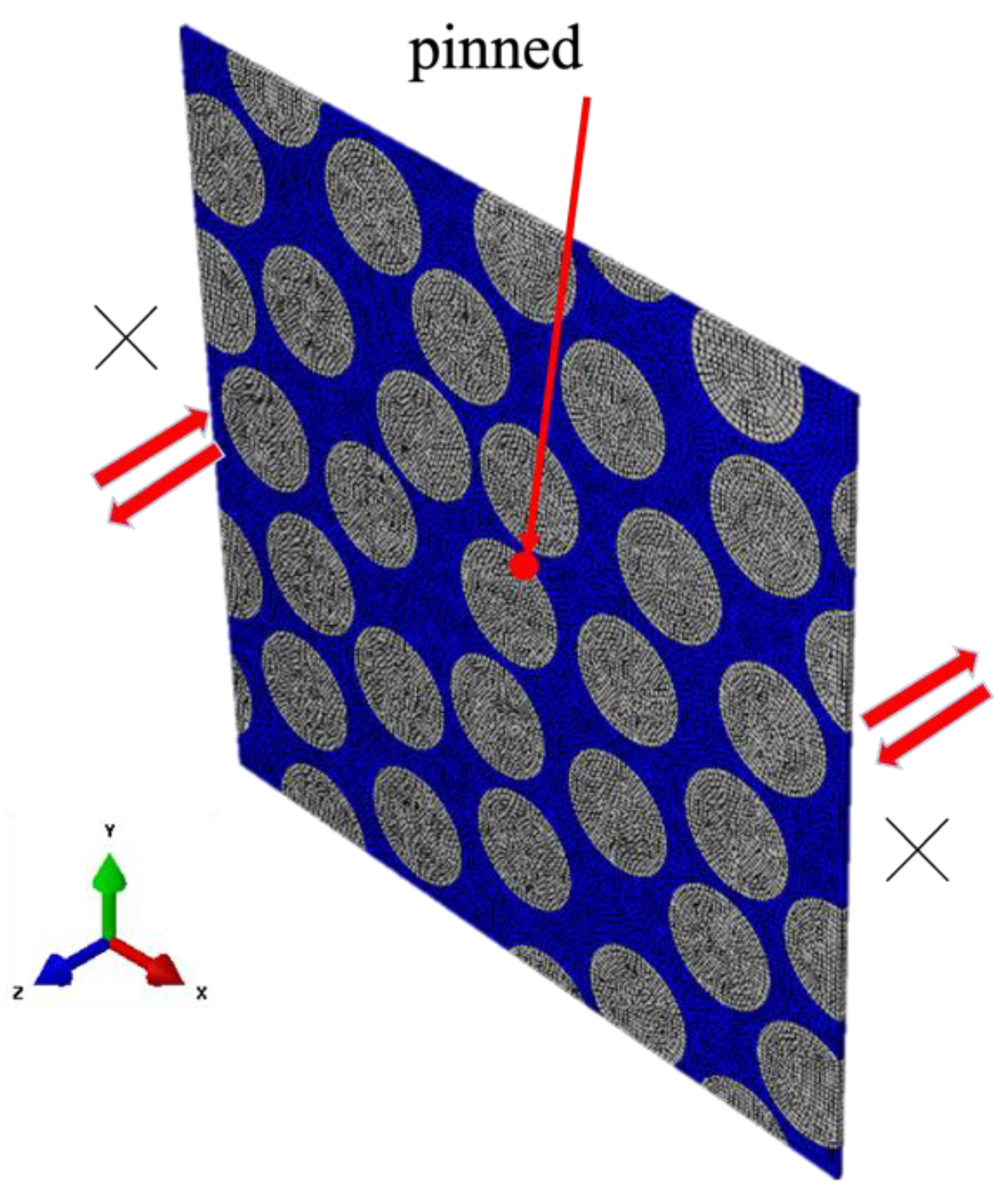
Figure 9.
Damage coefficient after cyclic tensile loading (strain 0.8%, 10cycle (upper left), 20cycle (upper right), 40cycle (lower left), 80cycle (lower right)).
Figure 9.
Damage coefficient after cyclic tensile loading (strain 0.8%, 10cycle (upper left), 20cycle (upper right), 40cycle (lower left), 80cycle (lower right)).
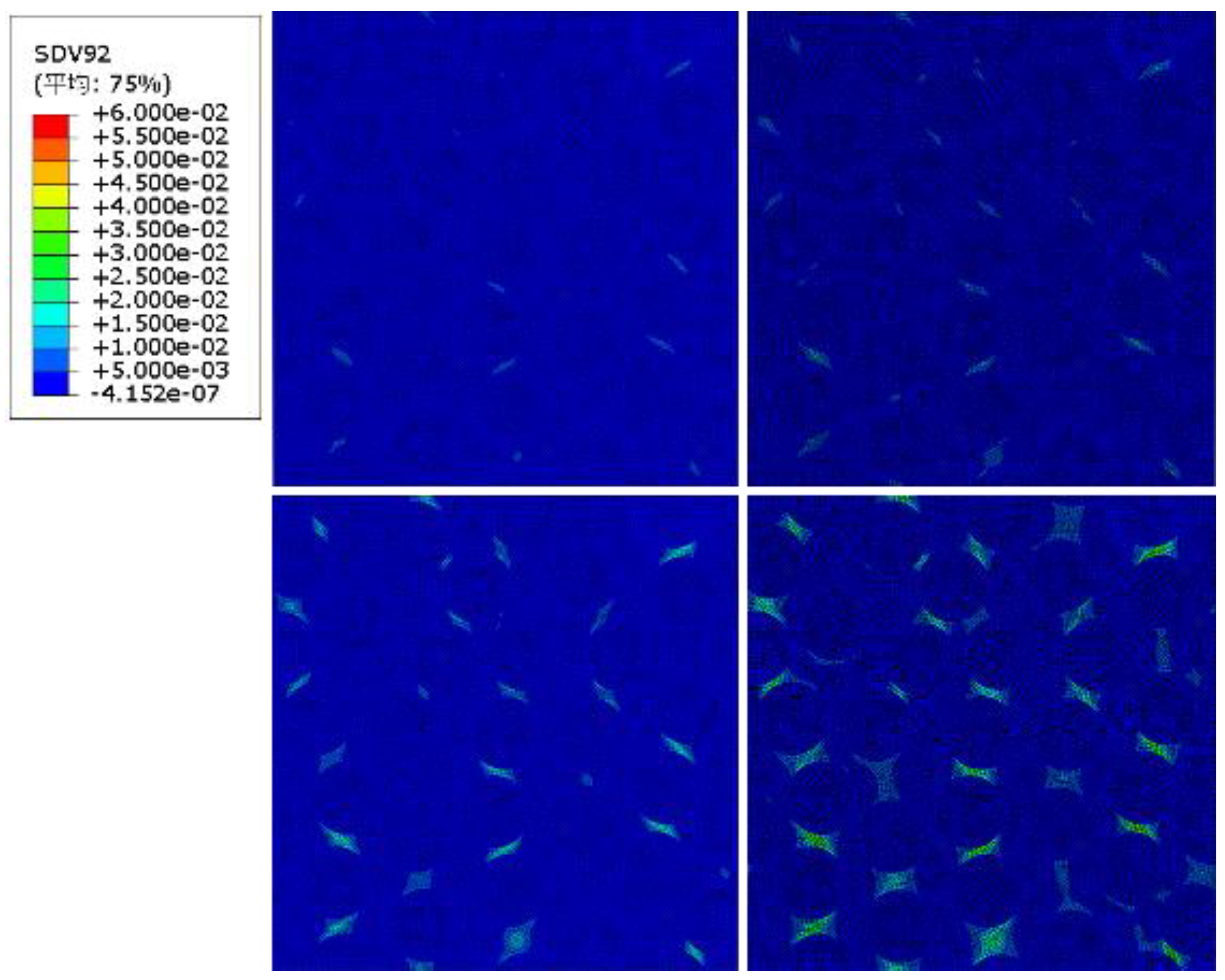
Figure 10.
Damage coefficient after cyclic out-of-plane shear loading (strain 0.8%, 10cycle (upper left), 20cycle (upper right), 40cycle (lower left), 80cycle (lower right)).
Figure 10.
Damage coefficient after cyclic out-of-plane shear loading (strain 0.8%, 10cycle (upper left), 20cycle (upper right), 40cycle (lower left), 80cycle (lower right)).

Figure 11.
fitted to the relationship between entropy and standardized residual strength under cyclic tensile loading.
Figure 11.
fitted to the relationship between entropy and standardized residual strength under cyclic tensile loading.
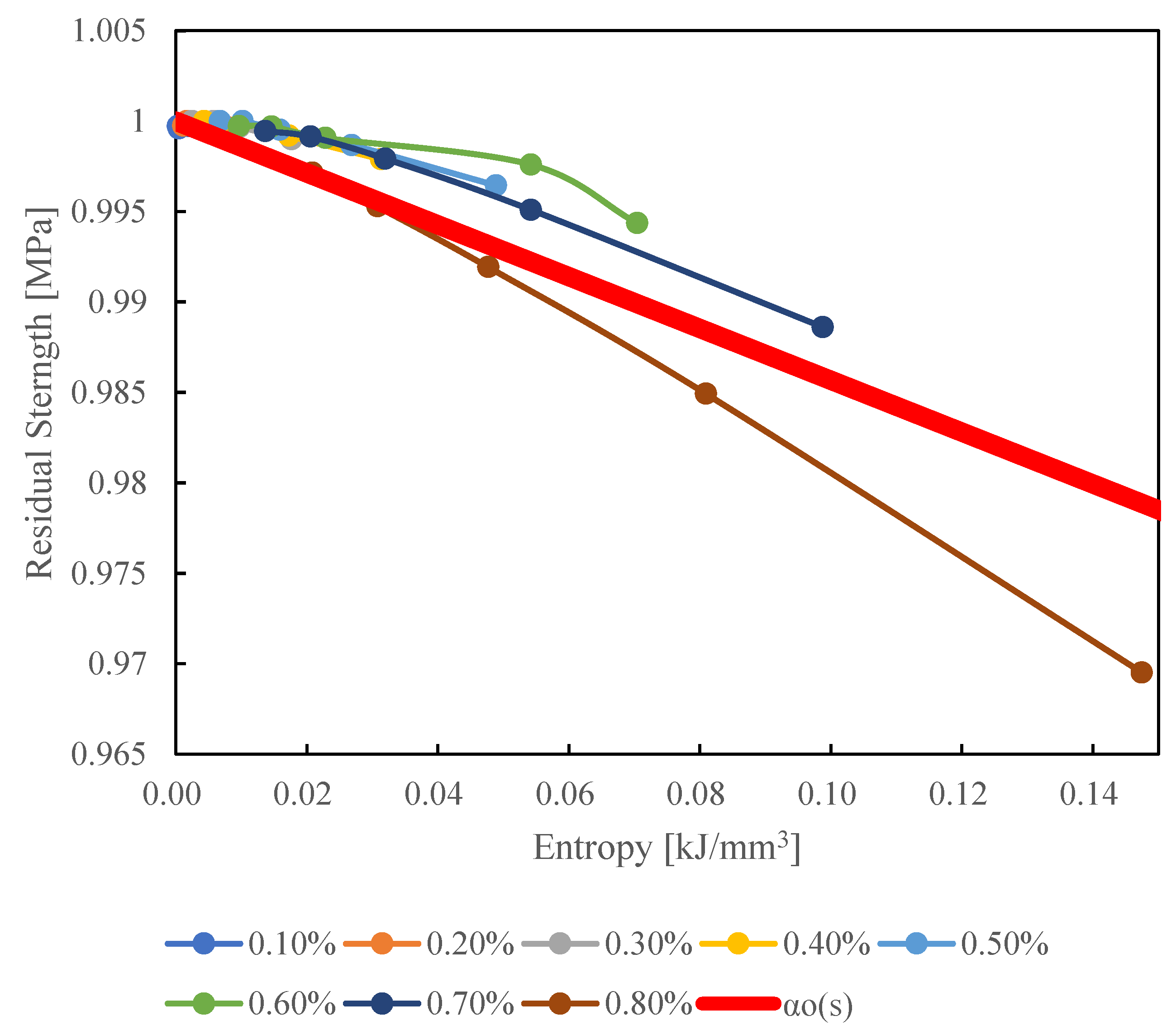
Figure 12.
fitted to the relationship between entropy and standardized residual strength under cyclic out-of-plane shear loading.
Figure 12.
fitted to the relationship between entropy and standardized residual strength under cyclic out-of-plane shear loading.
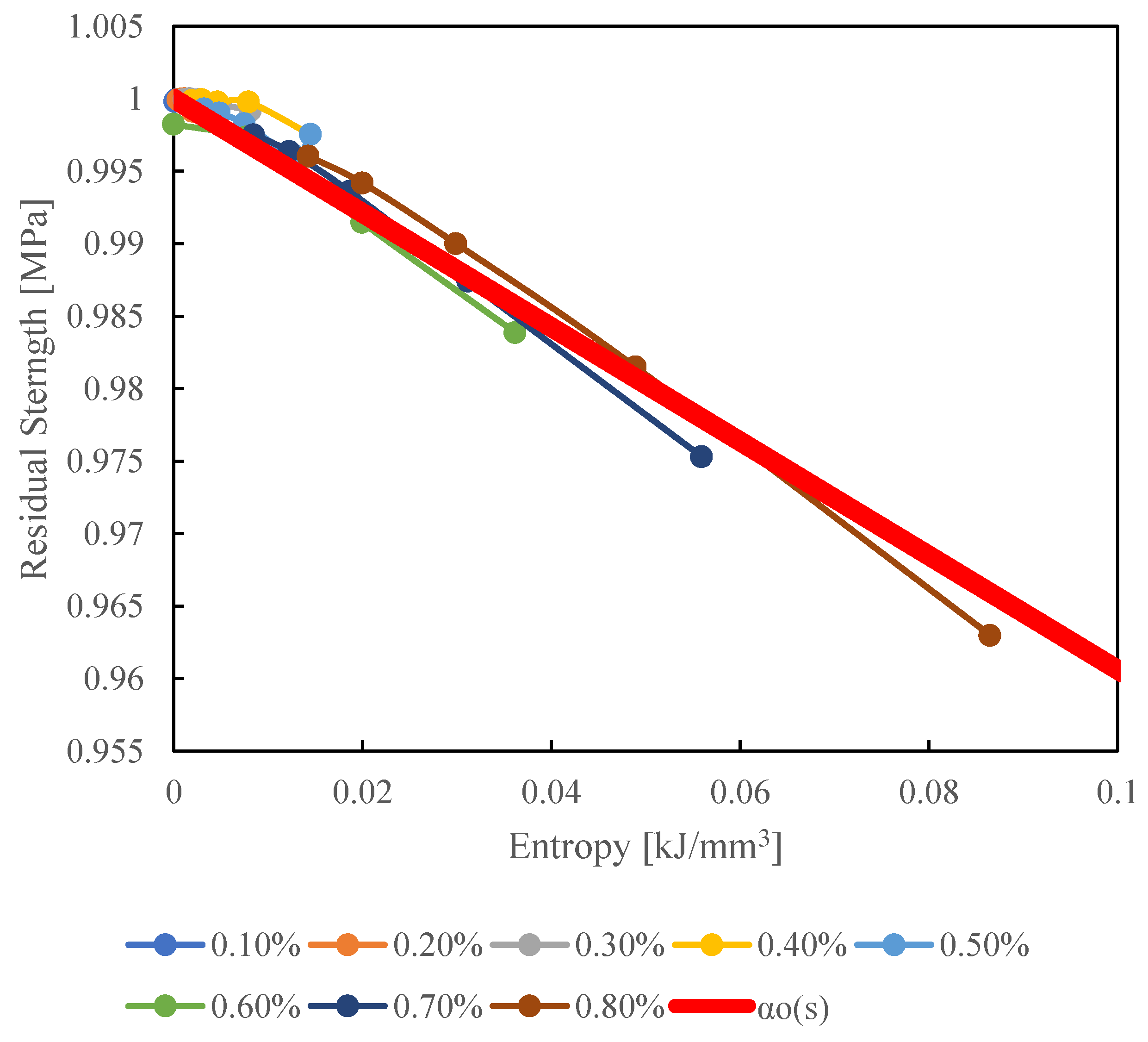

Table 1.
Material properties of springs and dashpots for viscoelastic model.
| j | [MPa] | [MPa・s] |
| 1 | 220 | 2.5×10³ |
| 2 | 220 | 6.3×10⁵ |
| 3 | 220 | 1.6×10⁷ |
| 4 | 220 | 6.3×10⁷ |
| 5 | 220 | 7.9×10⁸ |
| 6 | 220 | 2.0×10⁹ |
| 7 | 220 | 7.9×10⁹ |
| 8 | 220 | 3.2×10¹⁰ |
| 9 | 220 | 1.6×10¹¹ |
| 10 | 220 | 4.0×10¹¹ |
| 11 | 220 | 2.0×10¹² |
| 12 | 220 | 1.0×10¹³ |
| 13 | 220 | 7.9×10¹³ |
| 14 | 220 | 2.0×10¹⁵ |
| 15 | 220 | 1.0×1035 |
Disclaimer/Publisher’s Note: The statements, opinions and data contained in all publications are solely those of the individual author(s) and contributor(s) and not of MDPI and/or the editor(s). MDPI and/or the editor(s) disclaim responsibility for any injury to people or property resulting from any ideas, methods, instructions or products referred to in the content. |
© 2024 by the authors. Licensee MDPI, Basel, Switzerland. This article is an open access article distributed under the terms and conditions of the Creative Commons Attribution (CC BY) license (http://creativecommons.org/licenses/by/4.0/).
Copyright: This open access article is published under a Creative Commons CC BY 4.0 license, which permit the free download, distribution, and reuse, provided that the author and preprint are cited in any reuse.


