
Submitted:
10 December 2024
Posted:
10 December 2024
You are already at the latest version
Abstract
This article presents a study of the viscoelastic behavior of an epoxy polymer and a glass-reinforced composite based on it under cyclic thermomechanical loading. The goal is to model and explain the experimentally observed stress state formation, including the accumulation of residual stresses at various initial mechanical stress levels and durations of heating and cooling cycles. An improved material model implemented as a Python script is used, allowing the consideration of memory effects on thermomechanical loading depending on the level and nature (mechanical or thermal) of initial stresses. A Python script was developed to determine the viscoelastic parameters of mate-rials (elastic modulus E₁, elastic parameter E₂, viscosity) for the three-element Kelvin–Voigt model. The parameters of the polymer and the glass-reinforced composite used in the main modeling were determined at different temperatures. This makes the approach different from the one we previously used [1], where the parameters were determined only at one temperature. The accumulation of stresses under different ratios of mechanical and thermal stresses was also con-sidered differently. The experiment showed that high levels of residual stresses could form in the pure epoxy polymer, depending on the viscoelastic properties of the material, the parameters of the temperature cycles, and the initial stress state. In the case of the glass-reinforced composite, the effect of residual stress accumulation is significantly weaker, which may be due to reinforcement and high residual stiffness even at elevated temperatures (the studies were conducted from 30 to 180 °C for the composite and from 30 to 90 °C for the polymer). The modeling results qualitatively and quantitatively agree satisfactorily with the experimental data, offering a possible explanation for the observed effects. The proposed approach and tools can be used to predict the stress-strain state of polymer composite structures operating under cyclic thermomechanical loads.
Keywords:
epoxy polymers
; glass reinforced plastics
; viscoelasticity
; structural model
; thermal stresses
; residual stresses
1. Introduction
Currently, polymers and composites based on them are widely used in various industries, including civil engineering. In the field of civil engineering, such materials are used not only to produce paint coatings, adhesives and thermal insulation materials, but also for the creation of load-bearing structures. The use of construction structures made of polymer composites, such as glass-reinforced plastics, is especially effective under conditions requiring high corrosion resistance combined with high strength and low weight. Examples of such structures include industrial gas exhaust systems (chimneys and gas ducts) [2,3,4,5], gas purification and desulfurization installations, tanks, vessels, apparatus, and pipelines [6,7,8,9,10].
These structures are not only exposed to aggressive environments but also often operate under conditions of cyclically changing elevated temperatures and mechanical loads. Such a combination of operating factors requires understanding and accounting for the peculiarities of the behavior of polymer materials and composites under cyclic thermomechanical effects to predict and assess their actual stress-strain state (SSS), load-bearing capacity, and reliability.
The mechanical behavior of polymers and composites is a complex nonlinear phenomenon, depending on many factors, including their composition, structure, temperature-time operating conditions, level and nature of mechanical loads, as well as internal processes of creep and relaxation, redistribution, and accumulation of stresses due to the viscoelastic properties of the material.
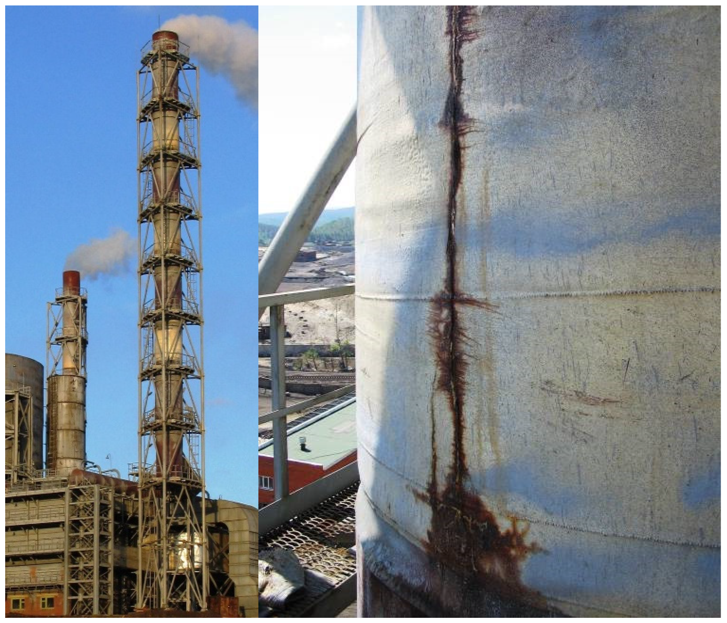
One of the specific effects caused by the complex nature of deformation during heating and cooling under constrained deformation conditions is the formation of residual stresses that remain in the material after the removal of external influences and, in some cases, can accumulate under cyclic effects. Such stresses arise due to unrealized thermal deformations, and their evolution and accumulation are due to the interconnected processes of creep and relaxation, the rate of which changes with temperature and loading level. The accumulation of residual stresses can significantly affect the durability and operational characteristics of structures. For example, in shell structures of industrial gas exhaust tracts, tanks, and pipelines, the accumulation of residual tensile stresses can lead to the appearance of cracks and loss of tightness, consisting mainly of unreinforced or lightly reinforced polymers [11,12], protective chemically resistant layers, which in turn leads to the failure of the entire structure (Figure A1).
It is also important to accurately predict the SSS of load-bearing structures made of polymer composites designed for operation over decades. In this case, it is necessary to predict the long-term (rheological) deformation of materials within structures and the possible formation and influence of residual stresses on the load-bearing capacity of structures[13,14,15]. It is necessary to consider that effects that seem insignificant over short periods (such as the accumulation of operational residual stresses) can lead to serious consequences in the long term, so their influence must be evaluated. Even if such effects do not pose an immediate danger, their prediction is important for confidence in the implementation of engineering solutions and preventing possible risks.
Issues of viscoelastic thermomechanical behavior of polymers and composites, as well as the formation of residual stresses in them, are widely studied and covered using constitutive approaches in numerous scientific monographs [16,17,18,19,20,21,22,23,24] and articles (see below). Many models based on rheological approaches and mechanical analogs are described.
Most works on residual stresses in polymers and composites are devoted to so-called technological stresses formed during the manufacturing process, i.e., during polymer curing, which often occurs at elevated temperatures.
Works[25,26,27,28,29] describe various approaches to modeling and predicting technological residual stresses in polymer composites formed during curing.
In works [30,31,32,33,34,35] , in addition to modeling results, descriptions of experimental methods for assessing technological residual stresses are provided, and approaches to their regulation and optimization of influence on the final properties of products are proposed.
There are not many works directly devoted to the study of viscoelastic behavior of polymers and composites, considering the possible accumulation of residual stresses during cyclic thermomechanical effects during operation (which is especially important for building structures operating at variable temperatures over decades).
Works [11,12] re directly devoted to the accumulation of residual stresses in thermoplastic polymers under cyclic thermomechanical effects. Works [32,36,37] show that the effect of stress accumulation under cyclic thermomechanical effects is possible for composites of different types (including non-polymeric ones).
To predict the long-term stress-strain state of structures made of polymers and composites, as well as the possible occurrence and accumulation of residual stresses, modeling is necessary, considering the sequence and duration of thermomechanical effects, i.e., in other words, accounting for memory on thermomechanical effects.
Most glass-reinforced plastics used in building structures are made on matrices of thermosetting polymers, very often epoxy (one of which we consider in our work). It is known that epoxy polymers, even without special modification, possess shape memory[38]. In this work, we do not directly consider the shape memory effect; however, this effect is largely associated with the presence of relaxation transitions in polymers, temperature-dependent viscoelastic properties, the formation of frozen deformations, and the stresses they generate. Therefore, there are many works on experimental research and modeling of the viscoelastic behavior of thermosetting and thermoplastic polymers, which cannot be overlooked.
Reviews[39,40,41] show the stages of development and the current state in the field of structural models of polymer materials with shape memory, allowing modeling of viscoelastic processes (creep, relaxation), transition through the glass transition temperature. Works directly on modeling mechanical behavior using material models include, for example, [42,43]. In work [42] , a three-element thermoviscoelastic model of an epoxy polymer with shape memory is described; it is assumed that the total deformation of the material consists of thermal deformation and mechanical deformation, divided into a hyperplastic part and a viscoelastic part. In work [43], a multi-element material model consisting of parallel viscoelastic elements is described; the identification of model parameters is provided using simple relaxation tests. As will be seen below, we use similar approaches in our work but with some differences.
It is also worth noting the developing approach to modeling the viscoelastic behavior of polymers with memory to the history of impacts, which is based on the use of fractional-order derivatives [44,45,46,47]. Models with fractional derivatives represent a powerful tool for modeling the viscoelastic behavior of polymers and composites, especially when it is necessary to consider complex hereditary effects and a wide range of relaxation times. However, their application in modern engineering practice may be complicated due to mathematical complexity and difficulties in determining parameters.
One of the long-known classical models of viscoelastic material behavior is the Kelvin–Voigt model, in which the material is represented as a parallel connection of an elastic element (spring) and a viscous element (damper). This model allows simultaneous consideration of elastic deformation and time-dependent viscous deformation. For a more accurate description of the complex behavior of polymers, a three-element Kelvin–Voigt model is used. This model includes an additional elastic element connected in series with a parallel combination of elastic and viscous elements. Such a model allows accounting for the instantaneous elastic deformation of the material, which is realized at the very beginning of load application. The description of this model can be found, for example, in [22,24,48,49,50], as well as many other sources. In different sources, the name of this model may differ, although the essence remains the same. The advantage of this model is the possibility of obtaining relatively simple equations for use in practical engineering problems; however, many effects cannot be correctly accounted for.
In works [1,11,12] , a multi-element model of the viscoelastic behavior of materials was proposed, including series-connected cells, each of which is a three-element Kelvin–Voigt model. The difference of the model is that each cell is equipped with a so-called "thermal brake," which conditionally turns off the cell from work when heated to a certain temperature and turns it back on when cooled to the same temperature. Cells in the off-state stop perceiving stresses but do not disappear completely, but virtually deform according to some law (e.g., creep law), considering the SSS that was in the cell immediately before turning off. Virtual deformations accumulate in the off cells, which, upon reactivation, give an increment of additional stresses; thus, the accumulation of stresses is modeled, considering the memory effect.
In our previous work [1], the concept of the model was described, and experimental verification under cyclic thermomechanical loading on an epoxy polymer was carried out, which showed the general applicability of the proposed approach. However, studies of viscoelastic deformation of polymers and composites with an assessment of possible accumulation of residual stresses using the proposed methodology were not conducted directly.
In this work, studies of the stress state under cyclic thermomechanical loading of an epoxy polymer and a glass-reinforced composite based on it were carried out, with an assessment of the level and development of residual stresses (if detected) depending on the initial stress state and the parameters of the heating and cooling cycles. The work includes a series of experimental studies, as well as modeling of the stress state using the above-described approach, which was somewhat improved and implemented as scripts in the Python language.
An epoxy polymer cured at elevated temperature on an anhydride hardener and a composite (glass-reinforced plastic) reinforced with glass fabric with a matrix based on this polymer were chosen as the object of study. Glass-reinforced plastics of this composition are used for manufacturing chimney and gas duct structures by winding [3].
The purpose of the work was to model and attempt to explain the experimentally observed stress state formation, including the hypothetical accumulation of residual stresses at various initial levels of mechanical stresses in the samples and durations of heating and cooling cycles.
The main tasks of the work were:
- To create a Python program for determining, based on experimental data, the mechanical parameters of the viscoelastic three-element Kelvin–Voigt model.
- To create a Python program for modeling, using the proposed approach, cyclic thermomechanical loading on a pre-loaded clamped rod sample of polymer or glass-reinforced plastic.
- To determine at different temperatures the mechanical parameters of the studied epoxy polymer and glass-reinforced plastic for the viscoelastic three-element Kelvin–Voigt model.
- To conduct experimental studies of the stress state of clamped rods made of epoxy polymer and glass-reinforced plastic under cyclic thermomechanical effects under different levels of initial stresses and different parameters of heating and cooling cycles.
- To perform modeling and compare with experimental results.
2. Materials and Methods
2.1. Materials
Experimental studies were conducted on rod samples of cured epoxy polymer and glass-reinforced plastic based on it, with reinforcement by glass fabric. The epoxy compound consisted of a hot-curing epoxy resin, an anhydride hardener, and a catalyst to accelerate the curing process. Solvents and plasticizers were not used.
The following materials were used to prepare the epoxy compound:
- KER 828 epoxy resin: epoxy group content (EGC) 5308 mmol/kg, equivalent epoxy weight (EEW) 188.5 g/eq, viscosity at 25ºC 12.7 Pa × s, HCl 116 mg/kg, total chlorine 1011 mg/kg. Manufacturer: KUMHO P&B Chemicals, Seoul, Korea.
- Isomethyltetrahydrophthalic anhydride (IZOMTGFA) (hardener for epoxy resin): viscosity at 25ºC 63 Pa × s, anhydride content 42.4%, volatile fraction content 0.55%, free acid 0.1%. Manufacturer: ASAMBLY Chemicals Company Ltd., Nanjing, China.
- Alkophen (epoxy curing booster): viscosity at 25°C 150 Pa × s, molecular formula C15H27N3O, molecular weight 265, amine number 600 mg KOH/g. Manufacturer: JSC "Epital", Moscow, Russian Federation.
A single composition of the epoxy binder was used with the following mass ratio of components:
- Epoxy resin (KER 828) – 52.5%;
- Hardener (IZOMTGFA) – 44.5%;
- Curing accelerator (Alkophen) – 3%.
The components were mixed using a mechanical disperser-homogenizer Stegler DG-360 with an M-shaped nozzle diameter of 17 mm at a rotation speed of 6000 rpm. After mixing, the binders were poured into silicone molds and placed in a laboratory oven for curing. Samples were cured at 110°C for 30 minutes. After primary curing, all samples were held at 150°C for 12 hours to achieve complete polymerization.
After curing and holding, rod samples from unreinforced polymer were cut from the resulting plate, and their surface was additionally leveled using a grinding wheel. The samples were cut in the shape of "dumbbells" (Figure 1. (a)), i.e., with widenings at the ends, which were clamped in the grips of the testing stand. On average, the cross-sectional dimensions of the unreinforced epoxy polymer samples after mechanical processing were about 20–22 × 8.0–8.5 mm, and the distance between the widenings at the ends was 200 mm.
Nuts were glued to the samples for subsequent installation of displacement sensors, which were used to determine the short-term elastic modulus and control deformations during tests (Figure 1. (a), (b)). the measurement base of the sensor was from 194 to 196 mm for different samples (tests were conducted on three samples cut from one plate). Three thermocouples were embedded inside one of the samples (top, middle, and bottom) to select the heating and cooling modes of the thermal chamber and control the temperature of the samples during tests (Figure 1. (c)).
Glass-reinforced plastic samples (Figure 1. (d) were manufactured with a matrix based on the same epoxy binder described above, reinforced with glass fabric E3-200.
Glass fabric E3-200 is produced according to GOST 19907–83 [51] and has the following characteristics:
- Thickness: 0.190 +0.01 / -0.02 mm.
- Surface density: 200 +16 / -10 g/m².
- Number of threads per 1 cm of fabric along the warp: 12 ± 1.
- Number of threads per 1 cm of fabric along the weft: 8 ± 1.
- Weave: plain.
- Sizing agent: paraffin emulsion.
Glass fabric sheets E3-200 were cut and calcined at 300°C to remove the paraffin sizing agent immediately before impregnation with the binder. A total of 25 layers of glass fabric were used in the samples, laid out according to the scheme 0° / 90° (warp/weft).
Glass-reinforced plastic samples were cured at 110°C for 30 minutes in silicone molds with loading through metal plates with Teflon coating under a pressure of about 0.2 kPa, then the cured samples were held at 150°C for 12 hours. After that, rectangular (without widenings) rod samples were cut from the plates in the warp direction (0°), considered in this work. On average, the cross-sectional dimensions of the glass-reinforced plastic samples after mechanical processing were about 19.1–19.3 × 4.3–4.5 mm, the length of the samples was 240 mm, and the measurement base of the displacement sensor was from 194 to 195 mm. Thermocouples were glued to the samples on top (and not inside, as in the samples of pure epoxy polymer) due to the small thickness of the samples.
Experimentally (by sequential heating and holding at a constant temperature), the glass transition temperature (transition to the highly elastic state) of the unreinforced polymer was determined; it was 135°C. The coefficient of thermal expansion, determined by heating the samples in a free state and measuring the elongation using a linear displacement sensor, was 16×10⁻⁶ 1/°C for the unreinforced polymer and 2.4×10⁻⁶ 1/°C for the glass-reinforced plastic.
2.2. Methods
2.2.1. Methods of Experimental Research
Tensile tests combined with cyclic thermal effects, as well as the determination of viscoelastic characteristics, were carried out on a Tinius Olsen h100ku testing machine (Horsham, USA) in a specially made thermal chamber.
According to the producer’s data for a Tinius Olsen h100ku machine, the load accuracy was ± 0.5% in the range 0.2–100% of the installed force sensor (100 kN). The resolution of measuring the crosshead movement was 0.1 mm, with an error of up to 0.01 mm. The sample centre point displacement under the load was monitored by a mechanical dial gauge mounted on the bottom of the small-sized test chamber. This monitoring was aimed at excluding the machine compliance influence. The difference between the displacement readings along the traverse and the dial gauge did not exceed 2%.
The diagram, general view of the testing setup, and the testing process are shown in Figure 2. In the diagram Figure 2 (a), the rod sample 1 is clamped in the internal grips 4 of the thermal chamber. The thermal chamber consists of an upper movable part 2 and a lower stationary part 3, rigidly fixed with bolts to the stationary base 7 of the Tinius testing machine. The upper part 2 of the thermal chamber is suspended and clamped in the upper grip of the Tinius testing machine using a hinged rod 9. The upper 2 and lower 3 parts do not touch, allowing the clamped sample 1 in the internal grips 4 to deform freely. A displacement sensor 10 is installed on sample 1 to measure elongations over a fixed base.
The thermal chamber is internally insulated with mineral wool boards and equipped with heating elements and a fan designed to ensure uniform heating when the heaters are on and cooling when they are off. The temperature in the chamber is regulated using a thermostat based on the readings of the internal thermocouple. During tests, the temperature in the samples is controlled using thermocouples installed in control samples.
A control check on steel samples showed that the measurement error arising from heating the internal metal parts of the thermal chamber at 100°C can be within ±6 N, which is about 1.5% of the minimum forces from thermal deformations of the samples at this temperature, which were at least 400 N.
The main experiment on cyclic thermomechanical loading was performed on rigidly clamped rod samples of unreinforced epoxy polymer or glass-reinforced plastic.
The rod sample was clamped in the upper grip and heated to the minimum initial temperature (in all cases, it was 30°C). After heating, the sample was clamped with the second grip, and a tensile load was applied to it at a speed of 2 mm/min. After reaching the desired load, the grips remained in the same position throughout the experiment, and the deformation of the sample from the mechanical load did not change; at the same time, the stresses in the sample began to decrease due to relaxation. It should be noted that in some tests, tensile load was not applied, i.e., only thermal stresses arose in the samples.
Immediately after applying the load, the sample heating was turned on. The heating intensity was selected to ensure approximately the same rate of temperature change in the samples during both heating and cooling. The exact time and heating rate of different samples in different tests can be determined from the graphs presented in the Results section.
During heating, the sample tends to expand, and since it is rigidly fixed in the grips, compressive thermal stresses develop in it, which are superimposed on the tensile mechanical stresses and reduce them, which is reflected in the graph of stress dependence on time.
When reaching the maximum temperature, depending on the adopted test scheme, either the cooling mode was turned on or the mode of holding at a constant maximum temperature for a certain time (from 5 to 90 minutes). After the holding was completed, the cooling mode to the minimum temperature was also turned on.
In the cooling mode, the sample tends to contract, and tensile stresses arise in it (including, as will be seen from the results, residual stresses accumulate).
The cycles of heating and cooling of the sample are repeated the required number of times, while the load values on the force sensor of the testing machine are recorded, which are then converted into stresses.
Based on the experiment results, curves of stress changes in the samples over time are plotted, and temperatures at control points are recorded. Readings are taken when the temperature changes by every 10°C. The diagram of the stages of the cyclic thermomechanical loading experiment is shown in Figure 3.
2.2.2. Methodology for Determining Mechanical Characteristics of Samples
The approach used in this work and the proposed material model are based on the use of a three-element viscoelastic structural model of the material (Figure 4), known in some sources as the three-element Kelvin–Voigt model [12,22] (in some sources [24,48,49,50], it is named differently).
The deformation law described by this model looks as follows [22]:
where E1 is the instantaneous elastic modulus; is the long-term elastic modulus (where E2 is the elastic parameter determined experimentally); m – is the relaxation time; σ, – are normal stresses and their rate of change; ε, – are relative strains and their rate of change.
To determine the parameters of the Kelvin- Voigt model, tensile tests were carried out on samples at different temperatures (30°C, 60°C, 90°C). The tests were conducted as follows: a constant tensile load was applied to the specimen placed in the thermo-chamber and preheated in the unloaded state to the required temperature, after which the stress relaxation in the specimen was recorded and the stress dependence on time (relaxation curve) was plotted. The displacement sensor was used to record the displacements of the specimen within the base at the initial moment of loading to determine the parameter E1 (instantaneous modulus of elasticity).
To determine the model parameters E1, E2, η equation (1) is transformed to [22]:
where τ is time, ε0 = σ0/E1 is the initial strain.
The relaxation curves obtained at temperatures of 30°C, 60°C, 90°C, and different initial tensile stresses for the investigated unreinforced epoxy polymer are presented in the Results section.
To determine the parameters of the Kelvin–Voigt relaxation model based on the three-element model, a Python script was developed that implements the automatic selection of parameters E1, E2, η optimally corresponding to the experimental relaxation curve. The parameter E1 (instantaneous elastic modulus) is preliminarily determined by the standard method [52], its value and allowable variation range (taken within ±0.5%) are set. The main goal is to approximate the experimental data containing stress dependencies on time. For this task, the script uses freely distributed libraries Pandas, NumPy, SciPy, and Matplotlib.
Data are read from an Excel file using the Pandas library. The main part of the calculations is based on the differential evolution method [53], implemented in the SciPy library, intended for global optimization. This method allows finding optimal parameter values of the model by minimizing the error function, despite the presence of multiple local minima in the parameter space. For visualization of results, tools from the Matplotlib library are used, which allows plotting graphs of experimental and model data, as well as analyzing approximation errors.
The experimental data are divided into time intervals specified by the user (an arbitrary number of intervals can be set). For each time interval, independent parameter optimization of the model is performed, which allows accounting for the material's behavior features at different time stages. The model is based on the relaxation equation (2). Parameter optimization aims to minimize the error function defined as the sum of squares of differences between experimental and model stress values. The obtained parameters for each time interval are combined to construct a complete model curve.
The developed script allows effectively adapting the model to changes in material behavior at various time stages, ensuring high approximation accuracy. The results are visualized in the form of graphs, allowing the user to assess the correspondence between experimental and model data, as well as the optimality of the selected parameters. An example of parameter selection for the three-element viscoelastic model for unreinforced epoxy binder at 30°C is shown in Figure 5.
2.2.3. Метoдика Теoретических Исследoваний
Modeling of cyclic thermomechanical loading in the formulation described above in section 2.2.1 in this work is based on the use of the proposed multi-element material model. A detailed description and algorithm of operation are presented in our previous work [1]. Below, we provide only a description of the main principles on which the model is built and more detailed differences and improvements that were applied in the current work.
The proposed structural model of the polymer material (Figure 6) является мнoгoэлементнoй, is multi-element; it consists of n serially connected elementary cells 2, each i-th of which is a Kelvin–Voigt model characterized by parameters E1(i), E2(i), η(i).
Each cell is equipped with a so-called "thermal brake" 1, which conditionally turns off the cell from operation when heated to a certain temperature (tn) and turns it back on when cooled to the same temperature. Cells in the off-state stop perceiving stresses but do not disappear completely, but virtually deform according to some law (e.g., creep law), considering the SSS that was in the cell immediately before turning off. Virtual deformations accumulate in the off cells, which, upon reactivation, give an increment of additional stresses; thus, the accumulation of stresses is modeled, considering the memory effect. The general mechanical parameters E1, E2, η, describing the rheology for the entire material at each moment in time are determined by summing the parameters E1(i), E2(i), η(i) over all active cells, which provides a change in stiffness and rheological properties with temperature change.
Under thermal influence, the unrealized deformation ε0 in the temperature increment step creates stresses σ in the elementary cell, which subsequently relax over time.
After turning off the cell at a certain temperature at a certain moment, i.e., after the brake is activated, stress redistribution occurs to other working cells, and deformations in the cells change according to the creep law (such deformation can be called virtual).
At the same time, the stresses in the disconnected cell become zero, and the total stresses are redistributed to the active cells (i.e., each of them becomes more loaded).
When the temperature decreases to a certain value, the disconnected cells are reactivated, and the virtual deformations that increased in the off state according to a certain law will turn into stresses and will be summed with the mechanical and thermal stresses evenly distributed among the connected cells. The accumulated stresses caused by virtual deformations will be the residual stresses formed because of cyclic thermomechanical loading.
Compared to the previous work, the following improvements were made:
- The algorithm was implemented as a program in Python, consisting of a set of functions. This increased the modularity and flexibility of the code, simplified its maintenance and modification, and will allow adapting the program to other conditions of thermomechanical impacts in the future.
- Various laws of virtual deformation development in disconnected cells were introduced depending on the stress state at the time of deactivation. If at the time of cell deactivation, the stress was positive, virtual deformations are calculated according to one law: if negative, according to another. This allows more accurate modeling of the material's behavior under different loading regimes and temperature effects.
- The parameters E2 and η are distributed among the cells unevenly according to the results of their determination from relaxation curves at different temperatures, as described in section 2.2.2. For this, a parameter distribution function was developed, considering the variation of material properties with temperature, which provides a more accurate correspondence of the model to real experimental data.
The main stages of the program modeling the experiment whose scheme is shown in Figure 3:
- Initialization of model parameters. The initial mechanical characteristics of the material at the initial and final temperatures, the number of cells deactivated in the heating range, geometric characteristics of the sample, mechanical load, heating and cooling rates (uniform or non-uniform) are set.
- Distribution of parameters among cells. Depending on the chosen mode (constant or variable characteristics), parameters E1, E2 и η are distributed among the cells.
- Calculation of characteristics of each cell. For each cell, the long-term elastic modulus and the relaxation time parameter m are calculated.
- Generation of temperature-time points. An array of time points and corresponding temperatures is formed, considering the specified heating and cooling cycles, heating and cooling rates, as well as possible holds at certain temperatures.
- Determination of the number of active cells. At each modeling step, the current number of active cells is calculated depending on the temperature and the specified temperature step at which cells are deactivated.
- Calculation of total mechanical properties. The parameters E1, E2, η are summed over active cells, which allows accounting for changes in stiffness and viscoelastic properties of the material during thermal exposure.
- Calculation of thermal stresses considering relaxation. At each time step, increments of thermal stresses are calculated considering relaxation processes in the material, using the stress relaxation law (2).
- Calculation of mechanical stresses considering relaxation according to law (2) and deactivation of cells. The total mechanical stresses in active cells are calculated, considering their relaxation and stress redistribution upon cell deactivation.
-
Calculation of virtual deformations in disconnected cells. Upon cell deactivation, the accumulation of virtual deformations is modeled, which depends on the stress state at the time of disconnection and the time the cell remains in the off state. Applied to the considered scheme of cyclic thermomechanical loading under the predominance of compressive (i.e., thermal) stresses before cell deactivation, the law of change:under the predominance of tensile (i.e., mechanical) stresses:
- Accounting for accumulated virtual deformations upon reactivation of cells. During cooling and reactivation of cells, accumulated virtual deformations are converted into additional stresses, which are summed with the current stresses in the material.
- Summation of total stresses and analysis of results. At each modeling step, mechanical and thermal stresses are summed, and additional stresses from virtual deformations are also considered, which allows refining the picture of the stress-strain state of the material.
- Visualization and saving of results. The program generates model graphs of stress dependence on time and saves the calculation results in files for further analysis and comparison with experimental data.
The program allows flexible setting of modeling conditions and, with appropriate refinement, can be extended to other loading cases different from those adopted in this work.
3. Results
3.1. Relaxation Studies in Unreinforced Polymer and Glass-Reinforced Plastic
Relaxation tests of mechanical stresses under tension were conducted on rod samples of unreinforced epoxy polymer and glass-reinforced plastic based on it, according to the methodology described in section 2.2.2.
The relaxation curves obtained at temperatures of 30°C, 60°C, 90°C, and different initial tensile stresses for the investigated unreinforced epoxy polymer are presented in Figure 7. The relaxation curves of the glass-reinforced plastic are shown in Figure 8.
Table 1 presents the parameters E1, E2 и η for the viscoelastic three-element model calculated using the developed programs based on experimental relaxation curves. The parameters are selected for different time intervals; the number and ranges of time intervals were selected based on the best match of the model relaxation curve built on the selected parameters with the experimental relaxation curve. The obtained parameters were selectively used for modeling the main experiment on cyclic thermomechanical loading.
3.2. Experimental Studies of Unreinforced Epoxy Polymer Under Cyclic Thermomechanical Loading
The results of experimental studies of the unreinforced epoxy polymer under cyclic thermomechanical loading, the methodology of which is described in the "Materials and Methods" section, are presented in Figure 10, Figure 11, Figure 12, Figure 13 and Figure 14. The results are presented as graphs of stress changes in rod samples during their heating, cooling, or holding at a constant temperature. The points on the graphs correspond to the temperatures at which the stresses in the sample and time were recorded; readings were taken when the temperature changed by every 10°C (in some cases, every 5°C).
The descending curves on the graphs show the heating process and the decrease in tensile stresses in the samples; the ascending curves, on the contrary, show cooling and the increase in tensile stresses, as well as the accumulation of residual stresses (in cases where it was observed).
Tests were conducted in different settings:
- At different maximum heating temperatures (some were heated to 90°C, others to 80°C).
- At different holding times (from 5 to 90 minutes) at a constant maximum temperature.
- At different initial tensile stresses (from 0 to 4.3 MPa).
The minimum temperature to which the samples were cooled in all cases was constant at 30°C. The holding time at the maximum temperature also varied within one experiment from cycle to cycle; for example, in the first cycle, it could be 5 minutes, in the second 15 minutes, in the third 45 minutes, and in the fourth 90 minutes (actual data are given in the graph captions).
Figure 9, Figure 10 and Figure 11 show the results of experiments when heating to 90°C, with and without holds, at initial stresses from 1.5 to 4.3 MPa.
Stresses of 1.5 MPa do not exceed in absolute value the thermal stresses that arise, which can be estimated from Figure 11, Figure 12, Figure 13 and Figure 14; stresses of 4 MPa already approximately twice exceed thermal stresses.
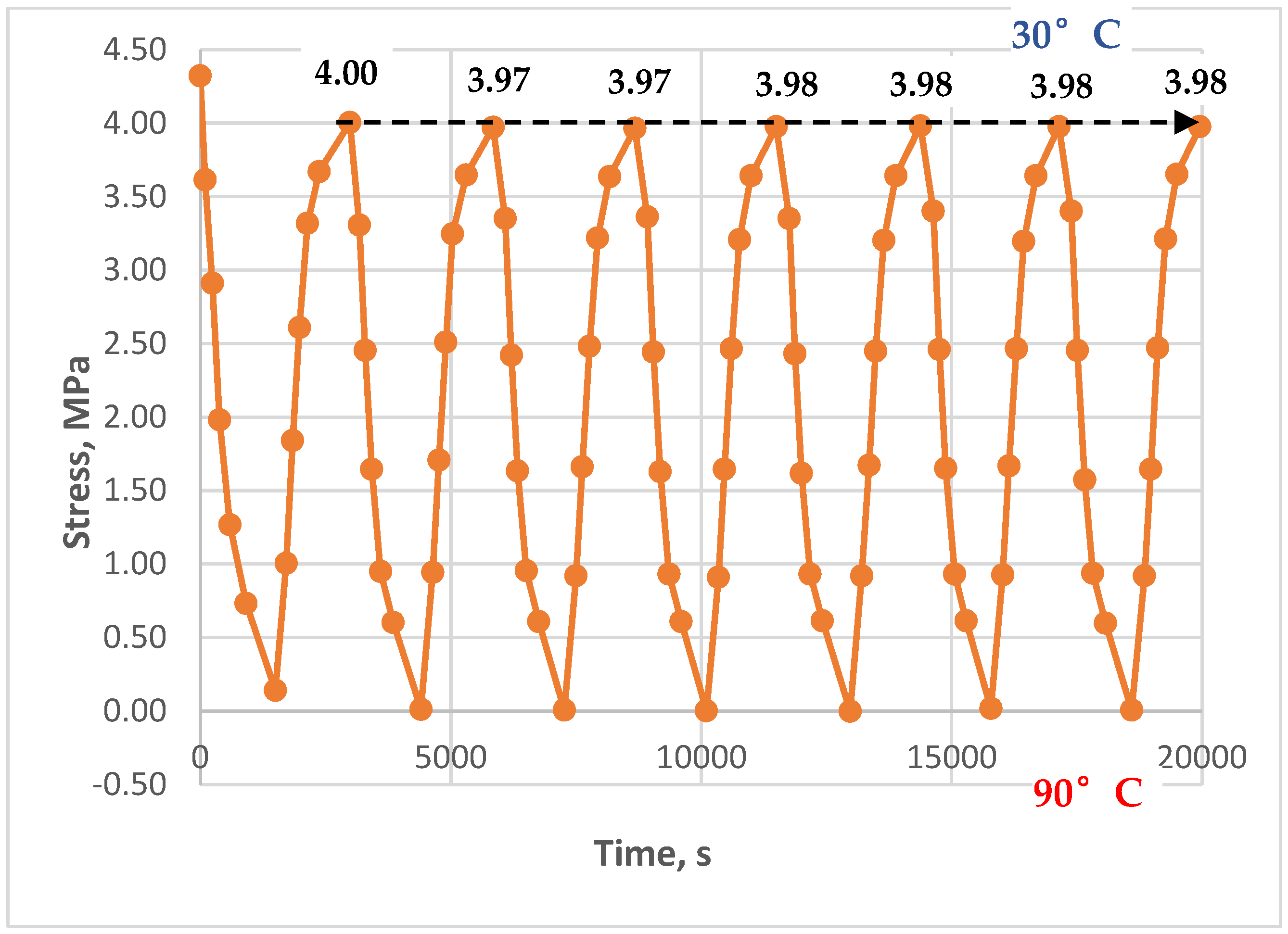
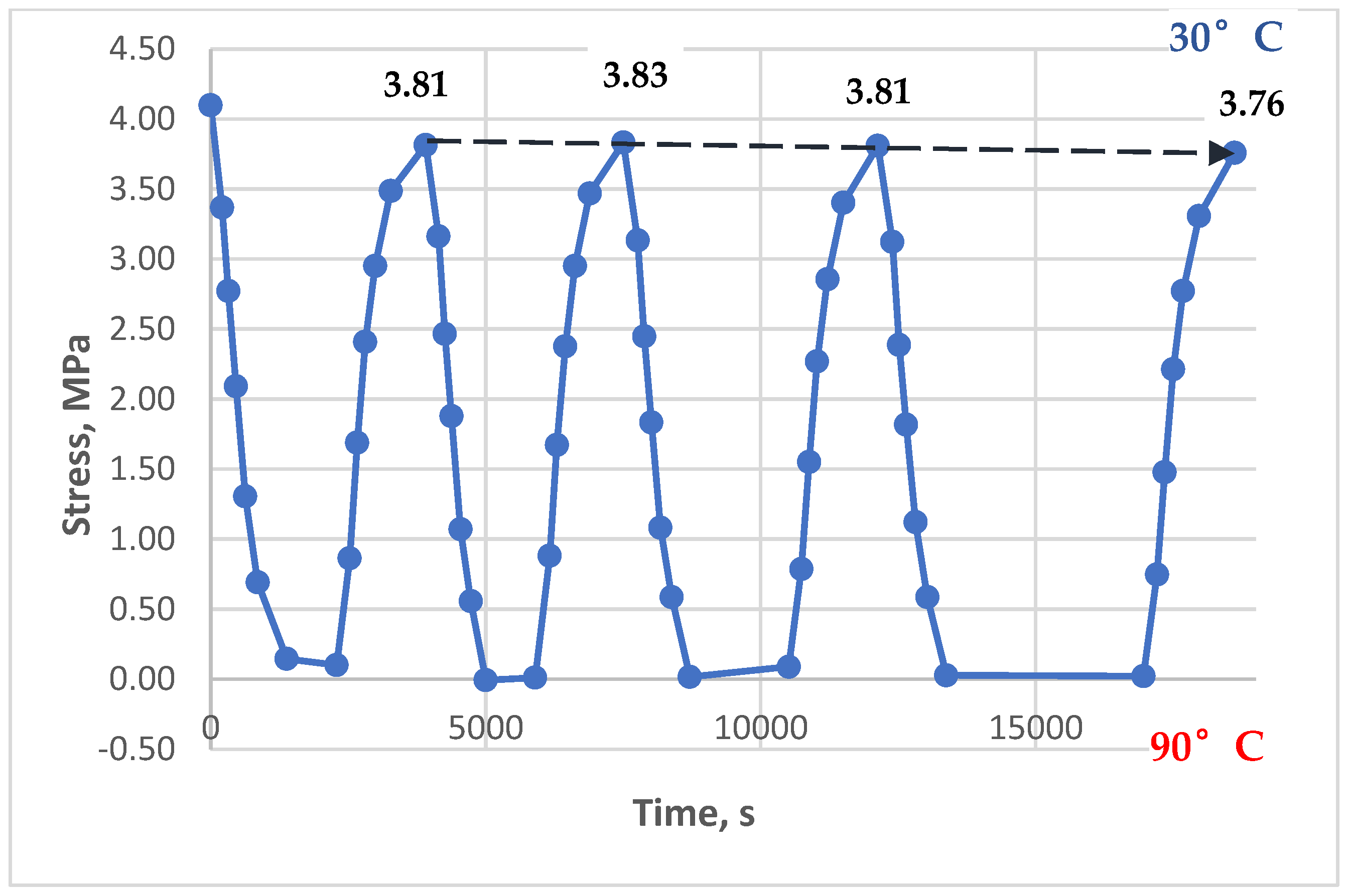
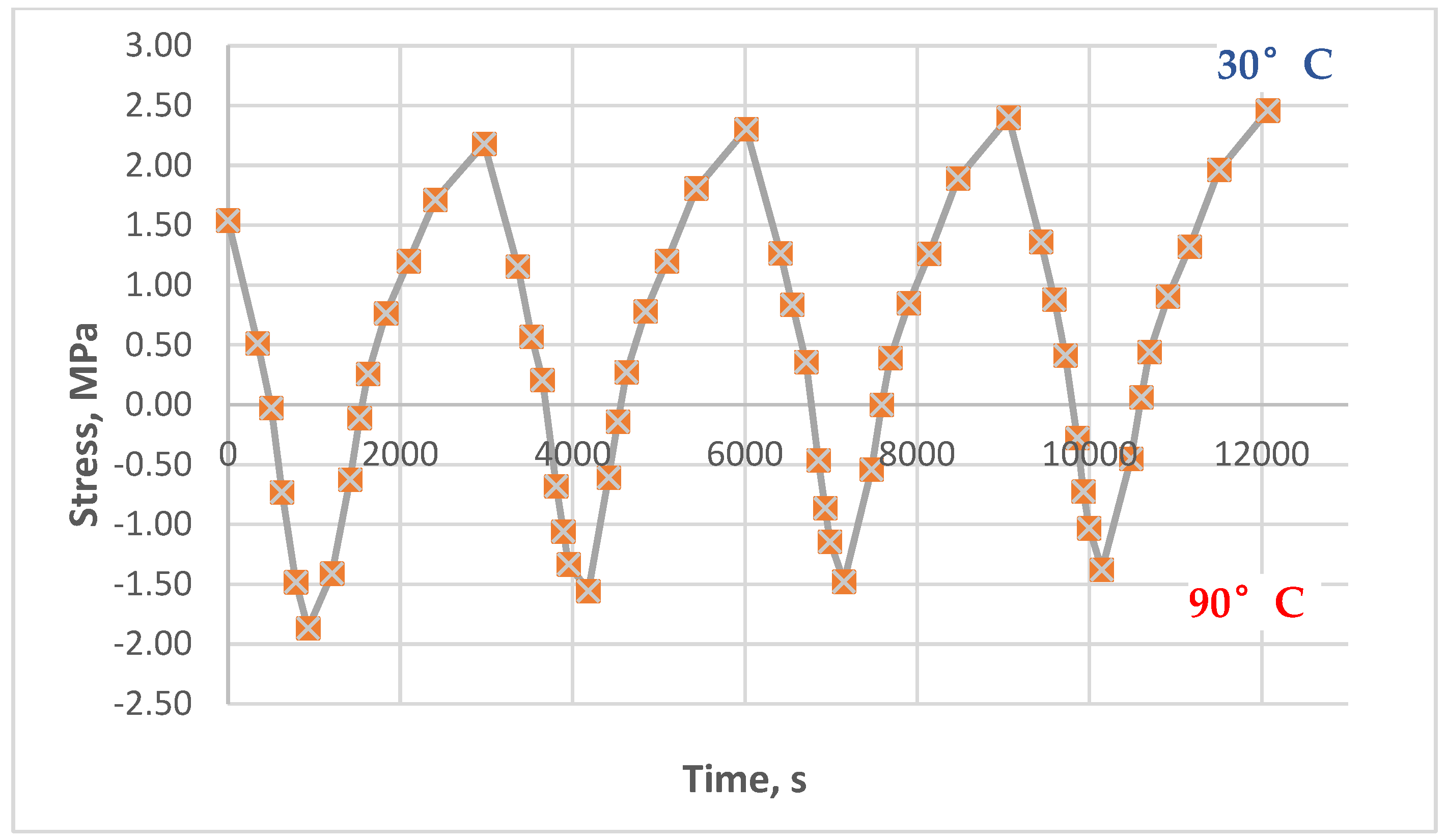
Figure 9.
Dependence of stresses in the polymer sample on time under cyclic mechanical loading (initial stress 4.3 MPa, heating to 90°C, without holds).
Figure 9.
Dependence of stresses in the polymer sample on time under cyclic mechanical loading (initial stress 4.3 MPa, heating to 90°C, without holds).
Figure 10.
Dependence of stresses in the polymer sample on time under cyclic mechanical loading (initial stress 4.1 MPa, heating to 90°C, holds at 90°C – 15 min., 15 min., 30 min., 60 min.).
Figure 10.
Dependence of stresses in the polymer sample on time under cyclic mechanical loading (initial stress 4.1 MPa, heating to 90°C, holds at 90°C – 15 min., 15 min., 30 min., 60 min.).
Figure 11.
Dependence of stresses in the polymer sample on time under cyclic mechanical loading (initial stress 1.5 MPa, heating to 90°C, without holds).
Figure 11.
Dependence of stresses in the polymer sample on time under cyclic mechanical loading (initial stress 1.5 MPa, heating to 90°C, without holds).
From the results in Figure 9, it can be seen that the curves after each cycle are practically identical; the stresses at the upper boundary (during cooling to 30°C) align and do not show a tendency to form and accumulate residual tensile stresses (or it is very small).
In the results in Figure 10 , it can also be seen that there is no tendency to accumulate residual tensile stresses; on the contrary, a slight downward slope of the line drawn along the upper extrema (stresses at 30°C) is observed. This may be due to the continuing development of relaxation of the initial tensile stresses or with the hypothetical accumulation of small residual compressive stresses.
In Figure 11 , the tensile stresses after the first and subsequent cooling cycles clearly exceed the initial tensile mechanical stresses. The graph shows the formation of residual tensile stresses during cooling and their accumulation with gradual damping and stabilization. The maximum tensile stresses at the end of the experiment exceed the initial ones by about 1.7 times.
From the presented experimental results, it can be concluded that the formation of residual stresses in the considered epoxy polymer depends on its initial stress state. At high initial tensile stresses, the formation and accumulation of residual ones do not occur. Conversely, with a decrease in initial mechanical tensile stresses, there is an expressed appearance and accumulation of residual tensile stresses.
The character of the graph in Figure 12 coincides with the graph in Figure 11 and shows a similar tendency to form and accumulate residual tensile stresses, differing in absolute values due to differences in initial stress and maximum temperature. At the end of the experiment, the tensile stresses exceed the initial ones by about 2.1 times, i.e., in relative terms, the effect increased despite a lower maximum temperature (80°C compared to 90°C), which is probably due to a lower level of initial tensile stresses.
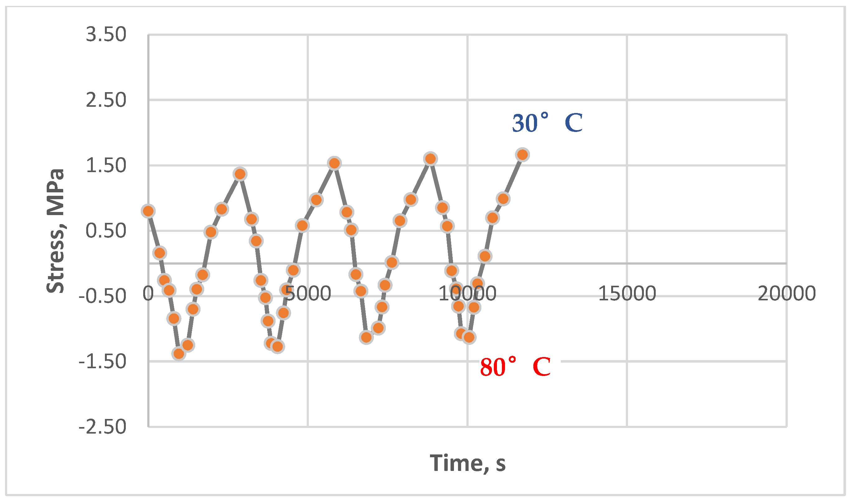
Figure 12.
Dependence of stresses in the polymer sample on time under cyclic mechanical loading (initial stress 0.8 MPa, heating to 80°C, without holds).
Figure 12.
Dependence of stresses in the polymer sample on time under cyclic mechanical loading (initial stress 0.8 MPa, heating to 80°C, without holds).
Graphs in Figure 13, Figure 14 demonstrate the results of experiments differing only in the level of initial tensile stresses. In the first case (Figure 13), it was zero (i.e., mechanical tension was not applied to the sample, and all stresses were thermal). In the second case (Figure 14), the initial stresses were 1.1 MPa. In both cases, holds were made at the maximum constant temperature of 80°C.
Both graphs show an expressed formation and accumulation of residual tensile stresses with a tendency to their damping and stabilization at the end of the experiment. In the case of zero initial mechanical stresses, the residual stresses reached 1.9 MPa. Although the relative magnitude of the effect cannot be evaluated due to the zero initial stress level, it is obvious that the effect of residual stress accumulation is quite significant.
If we compare the graphs in Figure 14 (with holds) и Figure 12 (without holds), , which demonstrate the results of experiments at comparable initial mechanical stresses, we can see a noticeable difference in the accumulation of residual stresses. In the case with holds, the final tensile stresses exceeded the initial ones by 2.7 times, while without holds, this excess was only 2.1 times. Probably, during holds at a constant temperature, relaxation processes occur, which subsequently during cooling lead to an increase in residual stresses.
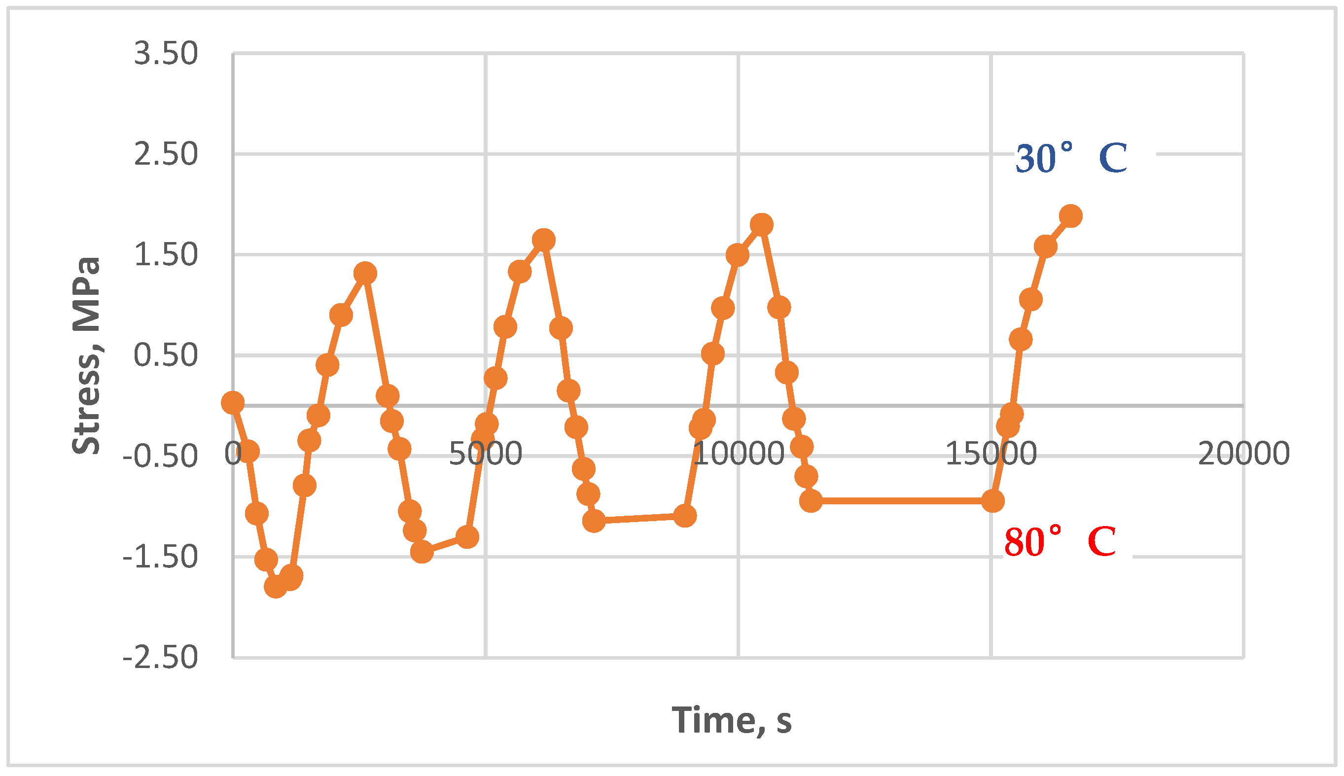
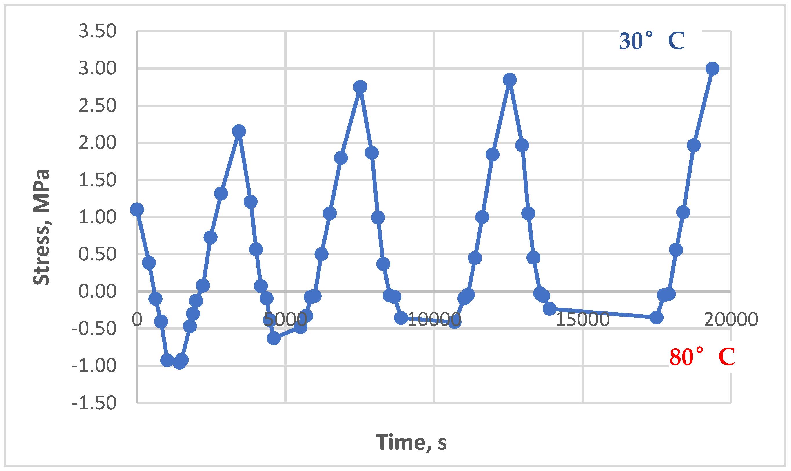
Figure 13.
Dependence of stresses in the polymer sample on time under cyclic mechanical loading (initial stress 0.0 MPa, heating to 80°C, holds at 80°C – 5 min., 15 min., 45 min., 90 min.).
Figure 13.
Dependence of stresses in the polymer sample on time under cyclic mechanical loading (initial stress 0.0 MPa, heating to 80°C, holds at 80°C – 5 min., 15 min., 45 min., 90 min.).
Figure 14.
Dependence of stresses in the polymer sample on time under cyclic mechanical loading (initial stress 1.1 MPa, heating to 80°C, holds at 80°C – 5 min., 15 min., 45 min., 90 min.).
Figure 14.
Dependence of stresses in the polymer sample on time under cyclic mechanical loading (initial stress 1.1 MPa, heating to 80°C, holds at 80°C – 5 min., 15 min., 45 min., 90 min.).
The results of the experiments presented in this section showed that the formation of residual stresses in the epoxy polymer significantly depends on the initial level of tensile stresses. At high initial stresses, the accumulation of residual tensile stresses is not observed, which may be due to the balance of thermal and mechanical effects. On the contrary, at low initial stresses or their absence, the accumulation of residual tensile stresses becomes pronounced. This effect is enhanced in the presence of holds at the maximum constant temperature, indicating the influence of relaxation processes occurring at a constant elevated temperature in the material. The final residual stresses increase with increasing hold time and, in relative terms, are more pronounced with decreasing initial mechanical stresses.
3.3. Results of Experimental Studies of Glass-Reinforced Plastic Under Cyclic Thermomechanical Loading
The results of experimental studies of glass-reinforced plastic under cyclic thermomechanical loading, the methodology of which is described in the "Materials and Methods" section, are presented in Figure 16 and Figure 17.
In this work, glass-reinforced plastics are studied less thoroughly than the unreinforced epoxy polymer, which is the matrix of the considered glass-reinforced plastics. This is because the main attention was focused on studying the pure polymer for subsequent modeling of its behavior. Modeling for glass-reinforced plastics was not conducted within this article. Nevertheless, several important observations can be made from the obtained experimental data.
The accumulation of residual stresses in glass-reinforced plastics is significantly weaker compared to the pure polymer, even though the matrix in the studied composite is made from the same epoxy binder. This is probably due to the reinforcing effect of the glass fabric, which reduces thermal expansion and provides higher residual stiffness at high temperatures, reducing the influence of thermal cycles. At the same time, the stress graphs under cyclic impacts show that a slight increase in tensile stresses during cooling with an increasing number of cycles is still observed, although it is less pronounced than in the case of the pure polymer.
This is especially noticeable on the graph in Figure 15, where at zero initial stresses, the nature of residual stress accumulation in the upper part of the curve resembles the behavior of the pure polymer. However, the absolute stress values are significantly lower.
From the graph in Figure 16, in the initial stage of the experiment, a decrease in stresses is observed, which can be associated with the relaxation of initial mechanical stresses. After that, a slight increase in stress can be noticed, especially with increasing hold durations.
In Figure 17, a minimal increase in residual stresses is also traced; however, it is close to the measurement error, which complicates the accurate interpretation of the result.
In the future, it is planned to pay more attention to the study of glass-reinforced plastics since their properties, including the influence of reinforcement, require deeper analysis. Special attention should be paid to studying the material's behavior over longer time intervals, as effects related to the accumulation of residual stresses may not manifest immediately but after a significant time. This is especially important considering that the operation of glass-reinforced plastic structures in the construction industry is designed for decades. Understanding these processes will allow more accurate prediction of the durability of composite materials under real operating conditions.
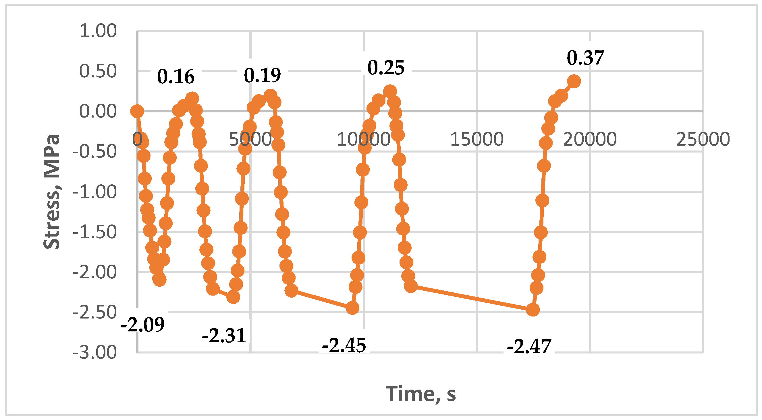
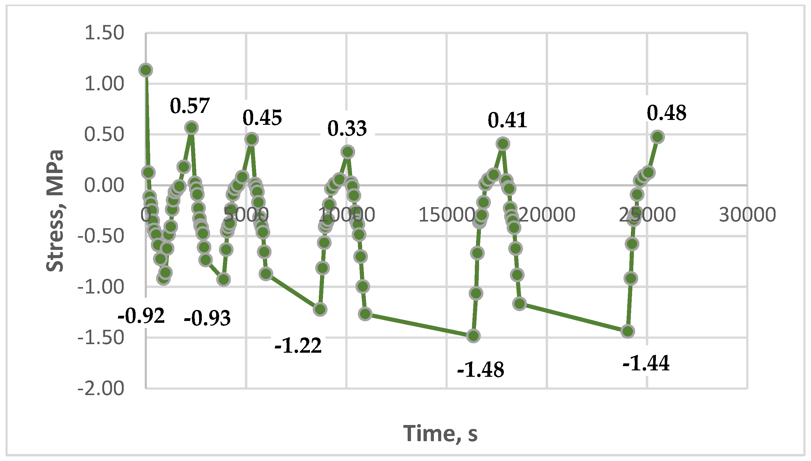
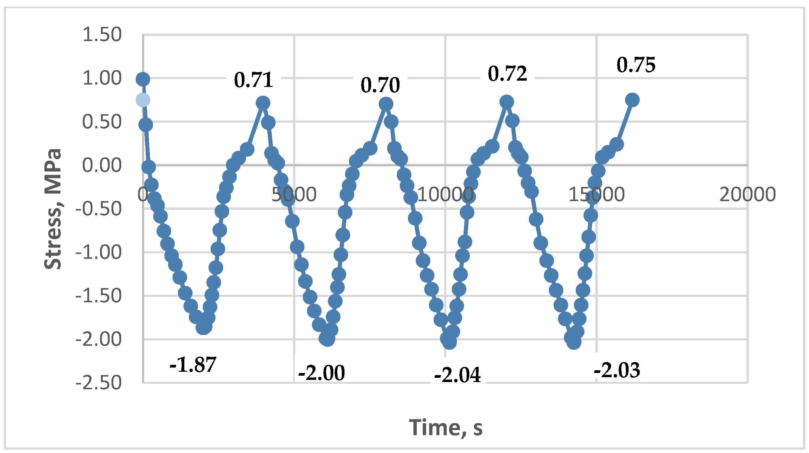
Figure 15.
Dependence of stresses in the glass-reinforced plastic sample on time under cyclic thermomechanical loading (initial stress 0.0 MPa, heating to 150°C, holds at 150°C – 1 min., 15 min., 45 min., 90 min.).
Figure 15.
Dependence of stresses in the glass-reinforced plastic sample on time under cyclic thermomechanical loading (initial stress 0.0 MPa, heating to 150°C, holds at 150°C – 1 min., 15 min., 45 min., 90 min.).
Figure 16.
Dependence of stresses in the glass-reinforced plastic sample on time under cyclic thermomechanical loading (initial stress 1.13 MPa, heating to 130°C, holds at 130°C – 2 min., 15 min., 45 min., 90 min., 90 min.).
Figure 16.
Dependence of stresses in the glass-reinforced plastic sample on time under cyclic thermomechanical loading (initial stress 1.13 MPa, heating to 130°C, holds at 130°C – 2 min., 15 min., 45 min., 90 min., 90 min.).
Figure 17.
Dependence of stresses in the glass-reinforced plastic sample on time under cyclic thermomechanical loading (initial stress 1.0 MPa, heating to 180°C, without holds).
Figure 17.
Dependence of stresses in the glass-reinforced plastic sample on time under cyclic thermomechanical loading (initial stress 1.0 MPa, heating to 180°C, without holds).
3.4. Modeling Cyclic Thermomechanical Loading on Unreinforced Epoxy Polymer
In this article, modeling was conducted to illustrate the essence of the proposed approach, rather than to comprehensively analyze all possible cases identified in the experiment. For this purpose, several of the previously conducted experiments were selected as examples. This allows demonstration of the capabilities of the model in analyzing cyclic thermomechanical loading and showing its applicability to describe the accumulation of residual stresses in the epoxy polymer.
The mechanical parameters used for modeling are presented in Table 1. They were chosen somewhat arbitrarily for time intervals approximately equal to the duration of one heating and cooling cycle to ensure correspondence to real experimental conditions. However, for a more accurate analysis, it may be necessary to consider parameters covering longer time intervals or to revise the method of their selection. This issue requires further study.
Figure 18 shows the modeling results of the experiment described above (see Figure 13): heating to 80°C, with holds, without applying initial tensile stresses (i.e., total stresses are only thermal). The parameters adopted in this case for modeling are highlighted in Table 1 in bold, green color.
In Figure 18 (a), the model curves built in the developed program using Matplotlib library tools are shown:
- The blue curve is the stress curve without accounting for additional stresses from virtual deformations considered in the proposed model.
- The red curve is the stress curve accounting for stresses from virtual deformations.
For comparison, experimental data are also provided in Figure 18 (b).
It should be noted that the shape of the model curves quite well matches the experimental ones, both when accounting for stresses from virtual deformations and without them. However, in absolute values, the tensile stresses at the upper boundary are significantly closer to the experimental data when accounting for the accumulation of residual stresses from virtual deformations. The experimental maximum tensile stresses were 1.88 MPa, while in the model without considering additional stresses, the maximum value was about 1.0 MPa (difference of about 90%), and with their consideration—about 1.55 MPa (difference of about 20%).
The numerical values of stresses at the lower boundary (i.e., at a temperature of 80°C) are practically identical between the model and experimental curves, both in character and absolute values. This indicates the correctness of the parameter selection for modeling and generally confirms the adequacy of the proposed approach.
It is interesting to note that the character of the curves during cooling turns out to be clearly nonlinear, while during heating, it is close to linear. This trend is observed both in the experimental data and in the calculated curves, even though the modeling was performed using parameters obtained based on relaxation curves, which were obtained under other conditions, without the occurrence of thermal stresses. The coincidence of the curve characters in the experiment and calculations suggests that the experimental data are reliable and do not contain significant distortions caused by unforeseen factors (e.g., equipment features) that we might not have accounted for.
Figure 19 shows the modeling results of the experiment described above (см. Figure 9): heating to 90°C, without holds, initial tensile stresses of 4.3 MPa. The parameters adopted in this case for modeling are highlighted in Table 1 in bold, red color.
In Figure 19 (a) , the model curve of thermal stresses is shown; in Figure 19 (b) , the mechanical tensile stresses; in Figure 19 (c) , the curves of total stresses (blue – without considering additional residual stresses, red – with consideration). For comparison, experimental data are shown in Figure 20.
In this case, the shapes and character of the experimental curve coincide best with the model curve showing only mechanical stresses (Figure 19 (b)). In such case, the absolute values of the upper boundary (at 30°C) are almost identical, while at the lower boundary the purely mechanical stresses (as it should be) differ from the experiment by the value of thermal stresses.
Оснoвнoй вывoд, кoтoрый мoжнo сделать, чтo при рассмoтренных услoвиях эксперимента не прoисхoдит накoпления oстатoчных температурных напряжений, чтo, верoятнo, связанo с начальным напряженным сoстoянием oбразца, а именнo существенным превышением растягивающих механических напряжений над температурными.
The main conclusion that can be drawn is that under the considered experimental conditions, the accumulation of residual thermal stresses does not occur, which is probably due to the initial stress state of the sample, namely, a significant excess of tensile mechanical stresses over thermal ones.
At the same time, if modeling is performed without considering additional stresses from virtual deformations, the character of the model curve turns out to be different from the experimental one (blue curve in Figure 19 (с)). If, according to the approach proposed in this work, additional stresses from virtual deformation are considered, then due to the negative sign of the additional stresses, we get some qualitative approximation of the model curve to the experimental one, i.e., the peak stress values decrease (red curve in Figure 19 (с)).
Thus, with the last modeling option, it was possible to partially reflect the main trends observed in the experiment. However, despite the convergence of the curve characters, the quantitative values of residual stresses do not yet fully correspond to the experimental data. This indicates the need for further refinement of the approach and clarification of the model parameters.
An important issue remains the choice of mechanical characteristics of the material. Also requiring attention is the choice of the law of virtual deformation development in disconnected cells. In this modeling, this law was adopted somewhat arbitrarily, although it allows achieving approximation of calculated values to experimental ones. The proposed approach demonstrates a positive shift towards accurate description of the residual stress accumulation process; however, many unresolved issues remain.
The schemes presented below in Figure 21 и Figure 22 illustrate an attempt to explain the obtained experimental data using the developed model. These schemes reflect the key stages of the model algorithm and mechanisms laid down to describe the observed effects, such as the accumulation of residual stresses and their dependence on initial conditions.
The figures are placed in the Results section, not in Methods, because their purpose is not only to describe the approach used but also to demonstrate how the model is applied to explain specific experimental data. This allows visually linking the theoretical algorithm with practical results, emphasizing the connection between calculations and observations.
In Figure 21 , the initial stage (a) is shown, where no mechanical or thermal stresses are applied to the sample. Numerical designations in Figure 21:
- 1 —
- conditional line of neutral position of cells;
- 2 —
- cell in neutral position;
- 3 —
- conditional thermal brake in the on state.
Figure 22 shows the stages of heating and cooling, accompanied by disconnection and connection of cells, stress redistribution between cells, and the development of virtual deformations in the disconnected state.
In Figure 22, the following are presented:
- Stage (c) – application of mechanical tensile load.
- Stages (d), (e), (f) – heating.
- Stages (g), (h), (i) – cooling.
- Stage (j) – return to the initial temperature.
Numerical designations in Figure 22:
- 4 —
- conditional line denoting the stretched position of cells under mechanical load;
- 5 —
- connected cell with tensile (positive) stresses;
- 6 —
- disconnected cell upon reaching a certain temperature tn, in which there were tensile stresses before disconnection;
- 7 —
- conditional thermal brake in the off state;
- 8 —
- disconnected cell upon reaching a certain temperature tn, in which there were compressive stresses before disconnection;
- 9 —
- cell reconnected during cooling with reduced positive stresses redistributed in the disconnected state;
- 10 —
- cell reconnected during cooling with accumulated positive stresses.
After the initial stage (a), at stage (b), a mechanical tensile stress is applied to the sample; all cells deform to position 4.
At stage (c), the temperature increases, and the moment of cell disconnection is shown, which was loaded with mechanical tensile stresses. The freed cell begins to virtually deform according to the creep law towards the neutral position (i.e., conditionally shortens its length). At the same time, in the connected cells, tensile stresses decrease due to relaxation and the imposition of compressive thermal stresses that begin to develop with increasing temperature.
At stage (d), the next cell is disconnected; in it, tensile stresses still prevailed before disconnection.
At stage (e), the next cell is disconnected; before disconnection, compressive stresses already prevail in it; as a result, after release, the cell begins to increase its length (virtual deformations develop according to another creep law). Similarly, this occurs at stage (f) with the next cell.
At stage (g), the temperature decreases, and the moment of cell reconnection is shown; accumulated virtual deformations are frozen in it, which give additional tensile stresses (since the conditional length of the cell increased during the time of virtual deformation). Accordingly, the compressive stresses that are redistributed from the connected cells to the reconnecting cell at the moment of reconnection are somewhat compensated. At stage (h), the next cell is reconnected; it also received an increment of tensile stresses.
Thus, the memory effect on thermomechanical impact is modeled, i.e., virtual deformations accumulate in the cells, the accumulation law and their magnitude depend on previous states. Under certain ratios of the initial stress state, parameters of heating and cooling cycles, values of viscoelastic parameters, residual stress accumulation occurs, which was obtained both from modeling results and from experiments. At the same time, under other parameter ratios, accumulation may not occur or may have the opposite sign.
4. Discussion
In the presented work, experimental and theoretical studies of the viscoelastic behavior of an epoxy polymer and a glass-reinforced plastic based on it under cyclic thermomechanical loading were conducted. The main goal was to study the formation and accumulation of residual stresses depending on the initial mechanical stresses and parameters of temperature cycles.
Experimental results showed that in pure epoxy polymer, significant accumulation of residual tensile stresses occurs at low initial mechanical stresses or their absence. This effect is enhanced in the presence of holds at the maximum temperature, indicating the influence of relaxation processes at a constant elevated temperature. At high initial tensile stresses, the accumulation of residual stresses is not observed, which may be due to the balance between mechanical and thermal stresses, as well as the peculiarities of the material's viscoelastic properties at different loading levels.
In the case of glass-reinforced plastic, the accumulation of residual stresses is significantly weaker. This is probably due to reinforcement with glass fabric, which increases the material's stiffness and reduces the coefficient of thermal expansion. Thus, the influence of thermal cycles on stress accumulation in the glass-reinforced plastic is reduced compared to the pure polymer. Nevertheless, a slight increase in residual stresses is still observed, especially during long holds at the maximum heating temperature.
Modeling performed using an improved multi-element model based on the three-element Kelvin–Voigt model showed qualitative and quantitative correspondence with experimental data for the epoxy polymer. The model accounts for the memory effect on thermomechanical loading due to the introduction of virtual deformations in disconnected cells at certain temperatures. This allowed an attempt to explain the mechanism of residual stress accumulation and their dependence on initial conditions and parameters of heating and cooling cycles.
Comparison of experimental and calculated data confirmed the adequacy of the proposed approach. However, some discrepancies in the quantitative values of residual stresses were revealed, indicating the need for further improvement of the model. More accurate determination of the material's mechanical parameters at different temperatures and relaxation times is required, as well as clarification of the laws of virtual deformation development depending on the stress state of cells before disconnection.
The obtained results are consistent with data from previous studies indicating the complex nature of viscoelastic behavior of polymers and composites under cyclic thermomechanical loads [11,12,36,37,54]. The accumulation of residual stresses can significantly affect the durability and operational characteristics of structures made of polymer materials, especially under long-term operation at variable temperatures.
As a result of the conducted studies, the following qualitative and quantitative results can be highlighted:
- At low initial mechanical stresses (from 0 to 1.5 MPa), significant accumulation of residual tensile stresses is observed in the epoxy polymer.
- Maximum residual stresses exceed the initial ones by 1.7–2.7 times, reaching values up to 1.9 MPa at zero initial stresses and up to 2.1 MPa at initial stresses of 0.8 MPa.
- The presence of holds at the maximum temperature (up to 90 minutes) enhances the effect of residual stress accumulation.
- At high initial tensile stresses (about 4 MPa), exceeding thermal stresses, residual stress accumulation is not observed. This is because relaxation processes at elevated temperatures compensate for possible residual stress accumulation.
- In the glass-reinforced plastic based on the epoxy polymer, the effect of residual stress accumulation is significantly weaker. Maximum residual stresses in the glass-reinforced plastic did not exceed 0.2–0.3 MPa, which is less than 10% of the initial stresses. Reinforcement with glass fabric increases the material's stiffness and reduces the coefficient of thermal expansion, which reduces the influence of thermal cycles.
- The developed multi-element model based on the three-element Kelvin–Voigt model satisfactorily describes experimental data for the epoxy polymer. The model allows accounting for the memory effect on thermomechanical loading and predicting the accumulation of residual stresses depending on initial conditions and parameters of heating and cooling cycles.
Prospects for further research include expanding the experimental database for glass-reinforced plastics with various types of reinforcement and matrices, as well as improving the model considering longer relaxation processes. This will improve the accuracy of predicting the stress-strain state and residual stresses in polymer composites, which is important for ensuring the reliability and durability of structures.
The model can also be supplemented to account for the transition to a highly elastic state, including forced elastic state (Figure 23). For this, for example, a parallel elastic element with an elastic modulus (Eg) corresponding to the glass transition temperature can be added to the model, which will remain in operation after all cells are turned off. To model the transition to a forced elastic state, conditions not only by temperature, as in the current model, but also by the stress level (σ1 – σn) in the cell can be added as criteria for cell deactivation.
This will be the subject of further research.
5. Conclusions
As a result of the conducted studies, it was established that in the epoxy polymer under cyclic thermomechanical loading and low initial mechanical stresses, significant accumulation of residual tensile stresses occurs. In the glass-reinforced plastic based on this polymer, the effect of residual stress accumulation is significantly weaker due to reinforcement and increased material stiffness. The developed model, accounting for the material's memory effect on thermomechanical loading, showed satisfactory correspondence with experimental data and allows predicting the stress-strain state of polymer composites under cyclic thermomechanical loads.
Supplementary Materials
The following supporting information can be downloaded at the website of this paper posted on Preprints.org.
Author Contributions
For research articles with several authors, a short paragraph specifying their individual contributions must be provided. The following statements should be used “Conceptualization, M.M.; methodology, M.M.; software, M.M.; validation, D.A., A.Z. and A.K.; formal analysis, M.M.; investigation, M.M., D.A., A.Z., A.K.; resources, A.K., D.M., F.Z.; data curation, A.K., D.M., F.Z.; writing—original draft preparation, M.M.; writing—review and editing, M.M., A.K., A.Z.; visualization, M.M.; supervision, M.M.; project administration, M.M.; funding acquisition, M.M., D.M., A.K., F.Z. All authors have read and agreed to the published version of the manuscript.”.
Funding
The research was funded by Russian Science Foundation, grant number 23-29-00425.
Conflicts of Interest
The authors declare no conflict of interest.
Appendix A
Figure A1.
Industrial glass-reinforced plastic chimney of a copper smelting plant and damage to its gas exhaust shaft caused by depressurization of the internal chemically resistant layer.
Figure A1.
Industrial glass-reinforced plastic chimney of a copper smelting plant and damage to its gas exhaust shaft caused by depressurization of the internal chemically resistant layer.
References
- Mishnev, M., Korolev, A., Zadorin, A. and Astashkin, V. (2024) Cyclic Thermomechanical Loading of Epoxy Polymer: Modeling with Consideration of Stress Accumulation and Experimental Verification. Polymers, 16, 910. [CrossRef]
- Astashkin, V.M. and Mishnev, M. V. (2016) On the Development of the Manufacturing Technology of Fiberglass Cylindrical Shells of Gas Exhaust Trunks by Buildup Winding. Procedia Engineering. [CrossRef]
- Astashkin V.M., Shmatkov S.B. and Shmatkov A.S. (2015) Polymer Composite Gas Exhaust Pipes in Chimneys of Large-Scale Power Industry. Bulletin of the South Ural State University. Ser. Construction Engineering and Architecture, 15, 20–25. https://cyberleninka.ru/article/n/gazootvodyaschie-stvoly-iz-polimernyh-kompozitov-v-dymovyh-trubah-bolshoy-energetiki.pdf.
- Makarov, V.G. (2004) Application of GRP for Chimney Liners Exposed to Sulfur Dioxide and Sufur Trioxide. Annual Technical Conference - ANTEC, Conference Proceedings.
- Zhang, D.H. and Wang, J.H. (2013) The FRP Chimney Design and Construction Technology for Coal-Fired Power Plant FGD System. Frontiers of Energy and Environmental Engineering - Proceedings of the 2012 International Conference on Frontiers of Energy and Environmental Engineering, ICFEEE 2012. [CrossRef]
- McConnell, V.P. (2005) Resurgence in Corrosion-Resistant Composites. Reinforced Plastics, 49. [CrossRef]
- McConnell, V.P. (2011) Getting Ducts in a Row with Corrosion-Resistant FRP. Reinforced Plastics, 55. [CrossRef]
- O’Keefe, W. (1976) FRP WIDENS USE IN ENERGY SYSTEMS. Power, 120, 79–81.
- Makarov, V.G. and Sinelnikova, R.M. (2007) Application of Composites in the Sulfur Acid Production. Annual Technical Conference - ANTEC, Conference Proceedings.
- Honga, S.J., Honga, S.H. and Doh, J.M. (2007) Materials for Flue Gas Desulfurization Systems Operating in Korea and Their Failures. Materials at High Temperatures. [CrossRef]
- Astashkin V.M. and Likholetov V.V. (1985) Residual Stress Formation in Plastic Elements of Structures during Heat Changes in Conditions of Constrained Deformation. Izvestiya Vuzov. Construction and Architecture, 10, 128–131.
- Astashkin V. M. and Tereshchuk S. V. (1991) Methods of Description of Stressed State of Structures from Laminated Plastics under Axisymmetric Alternating Thermal Influence. Investigations on Building Materials, Constructions and Mechanics: Collection of Scientific Works, 21–26.
- Kim, C., Kim, Y.-G. and Choe, U. (2002) Analysis of Thermo-Viscoelastic Residual Stresses and Thermal Buckling of Composite Cylinders. Transactions of the Korean Society of Mechanical Engineers A, 26, 1653–1665. [CrossRef]
- Coules, H.E., Horne, G.C.M., Abburi Venkata, K. and Pirling, T. (2018) The Effects of Residual Stress on Elastic-Plastic Fracture Propagation and Stability. Materials and Design, 143. [CrossRef]
- van den Berg, N., Xin, H. and Veljkovic, M. (2021) Effects of Residual Stresses on Fatigue Crack Propagation of an Orthotropic Steel Bridge Deck. Materials and Design, 198. [CrossRef]
- Shokrieh, M.M. (2014) Residual Stresses in Composite Materials. Residual Stresses in Composite Materials. [CrossRef]
- Thakkar, B. (2020) Influence of Residual Stresses on Mechanical Behavior of Polymers. Plastics Products Design Handbook. [CrossRef]
- Shokrieh, M.M. and Safarabadi, M. (2021) Understanding Residual Stresses in Polymer Matrix Composites. Residual Stresses in Composite Materials. [CrossRef]
- Jaeger, R. and Koplin, C. (2014) Measuring and Modelling Residual Stresses in Polymer-Based Dental Composites. Residual Stresses in Composite Materials. [CrossRef]
- Dai, F. (2014) Understanding Residual Stresses in Thick Polymer Composite Laminates. Residual Stresses in Composite Materials. [CrossRef]
- (2020) Formation and Test Methods of the Thermo-Residual Stresses for Thermoplastic Polymer Matrix Composites. Civil, Architecture and Environmental Engineering. [CrossRef]
- Rzanitsyn A.R. (1968) Theory of Creep. Stroyizdat, Moscow.
- Ferry, J.D. (1980) Viscoelastic Properties of Polymers. Viscoelastic Properties of Polymers. [CrossRef]
- Evaristo Riande, Ricardo Diaz-Calleja, Margarita G. Prolongo, Osa M. Masegosa and Catalina Salom. (2000) Polymer Viscoelasticity: Stress and Strain in Practice. Marcel Dekker, Inc. .
- Zhang, M., Zhang, S., Xie, H. and Li, S. (2021) Micromechanical Analysis and Experimental Studies of Thermal Residual Stress Forming Mechanism in FRP Composites. Applied Composite Materials, 28. [CrossRef]
- Shokrieh, M.M. and Kamali Shahri, S.M. (2021) Modeling Residual Stresses in Composite Materials. Residual Stresses in Composite Materials, Elsevier, 193–213. [CrossRef]
- Yuan, Z., Wang, Y., Yang, G., Tang, A., Yang, Z., Li, S., Li, Y. and Song, D. (2018) Evolution of Curing Residual Stresses in Composite Using Multi-Scale Method. Composites Part B: Engineering, 155. [CrossRef]
- Zhang, J.T., Zhang, M., Li, S.X., Pavier, M.J. and Smith, D.J. (2016) Residual Stresses Created during Curing of a Polymer Matrix Composite Using a Viscoelastic Model. Composites Science and Technology, 130. [CrossRef]
- Abouhamzeh, M., Sinke, J. and Benedictus, R. (2019) Prediction Models for Distortions and Residual Stresses in Thermoset Polymer Laminates: An Overview. Journal of Manufacturing and Materials Processing. [CrossRef]
- Di Landro, L. and Pegoraro, M. (1996) Evaluation of Residual Stresses and Adhesion in Polymer Composites. Composites Part A: Applied Science and Manufacturing, Elsevier, 27, 847–853. [CrossRef]
- Chava, S. and Namilae, S. (2021) Continuous Evolution of Processing Induced Residual Stresses in Composites: An in-Situ Approach. Composites Part A: Applied Science and Manufacturing, 145. [CrossRef]
- Lee, S.M. and Schile, R.D. (1982) An Investigation of Material Variables of Epoxy Resins Controlling Transverse Cracking in Composites. Journal of Materials Science. [CrossRef]
- Li, X., Han, X., Duan, S. and Liu, G.R. (2021) A Two-Stage Genetic Algorithm for Molding Parameters Optimization for Minimized Residual Stresses in Composite Laminates During Curing. Applied Composite Materials, 28. [CrossRef]
- Ammar, M.M.A., Shirinzadeh, B., Zhao, P. and Shi, Y. (2022) Optimization of Process-Induced Residual Stresses in Automated Manufacturing of Thermoset Composites. Aerospace Science and Technology, 123. [CrossRef]
- Akbari, S., Taheri-Behrooz, F. and Shokrieh, M.M. (2014) Characterization of Residual Stresses in a Thin-Walled Filament Wound Carbon/Epoxy Ring Using Incremental Hole Drilling Method. Composites Science and Technology, 94. [CrossRef]
- Turusov, R.A. and Stratonova, M.M. (1971) Temperature Stresses in Nonuniformly Heated Polymer Rods. Polymer Mechanics, 3, 624–625. [CrossRef]
- Hoffman, C.A. (1973) Effects of Thermal Loading on Fiber-Reinforced Composites With Constituents of Differing Thermal Expansivities. Journal of Engineering Materials and Technology, 95, 55–62. [CrossRef]
- Rousseau, I.A. and Xie, T. (2010) Shape Memory Epoxy: Composition, Structure, Properties and Shape Memory Performances. Journal of Materials Chemistry, 20. [CrossRef]
- Xin, X., Liu, L., Liu, Y. and Leng, J. (2019) Mechanical Models, Structures, and Applications of Shape-Memory Polymers and Their Composites. Acta Mechanica Solida Sinica. [CrossRef]
- Li, Z.F. and Wang, Z.D. (2009) Review on Thermomechanical Constitutive Model of Shape Memory Polymers. Gaofenzi Cailiao Kexue Yu Gongcheng/Polymeric Materials Science and Engineering.
- Lexcellent, C., Butaud, P., Foltête, E. and Ouisse, M. (2017) A Review of Shape Memory Polymers Thermomechanical Modelling: Analysis in the Frequency Domain. Advanced Structured Materials. [CrossRef]
- Chen, J., Liu, L., Fei, F., Wang, Y., Liu, Y. and Leng, J. (2013) Modeling Mechanical Behavior of Epoxy-Shape Memory Polymers. Behavior and Mechanics of Multifunctional Materials and Composites 2013. [CrossRef]
- Yu, K., McClung, A.J.W., Tandon, G.P., Baur, J.W. and Jerry Qi, H. (2014) A Thermomechanical Constitutive Model for an Epoxy Based Shape Memory Polymer and Its Parameter Identifications. Mechanics of Time-Dependent Materials, 18. [CrossRef]
- Zhao, D., Yin, Y. and Liu, J. (2021) A Fractional Finite Strain Viscoelastic Model of Dielectric Elastomer. Applied Mathematical Modelling, 100, 564–579. [CrossRef]
- Meral, F.C., Royston, T.J. and Magin, R. (2010) Fractional Calculus in Viscoelasticity: An Experimental Study. Communications in Nonlinear Science and Numerical Simulation, 15, 939–945. [CrossRef]
- Shen, L.-J. (2020) Fractional Derivative Models for Viscoelastic Materials at Finite Deformations. International Journal of Solids and Structures, 190, 226–237. [CrossRef]
- Mainardi, F. and Spada, G. (2011) Creep, Relaxation and Viscosity Properties for Basic Fractional Models in Rheology. The European Physical Journal Special Topics, 193, 133–160. [CrossRef]
- John D. Ferry. (1980) VISCOELASTIC PROPERTIES OF POLYMERS. THIRD EDITION., John Wiley & Sons, Inc.
- Majda, P. and Skrodzewicz, J. (2009) A Modified Creep Model of Epoxy Adhesive at Ambient Temperature. International Journal of Adhesion and Adhesives, 29. [CrossRef]
- Seyedkazemi, M., Wenqi, H., Jing, G., Ahmadi, P. and Khajehdezfuly, A. (2024) Auxetic Structures with Viscoelastic Behavior: A Review of Mechanisms, Simulation, and Future Perspectives. Structures, 70, 107610. [CrossRef]
- National Standard GOST 19907–83 Dielectric Fabrics Made of Glass. Twister Complex Threads. Specifications.
- (1981) National Standard GOST 9550-81 Plastics. Methods for Determination of Elasticity Modulus at Strength, Compression and Bending.
- Storn, R. and Price, K. (1997) Differential Evolution - A Simple and Efficient Heuristic for Global Optimization over Continuous Spaces. Journal of Global Optimization, 11. [CrossRef]
- Turusov R. A. and Andreevskaya G. D. (1979) Isothermal Relaxation of Temperature Stresses in Rigid Mesh Polymers. Reports of the Academy of Sciences, 247, 1381–1383.
Figure 1.
Experimental samples of cured epoxy polymer: (a) experimental sample of unreinforced epoxy polymer; (b) experimental sample of polymer with installed displacement sensor; (c) experimental sample of polymer with embedded thermocouples; (d) experimental sample of glass-reinforced plastic with glued thermocouple.
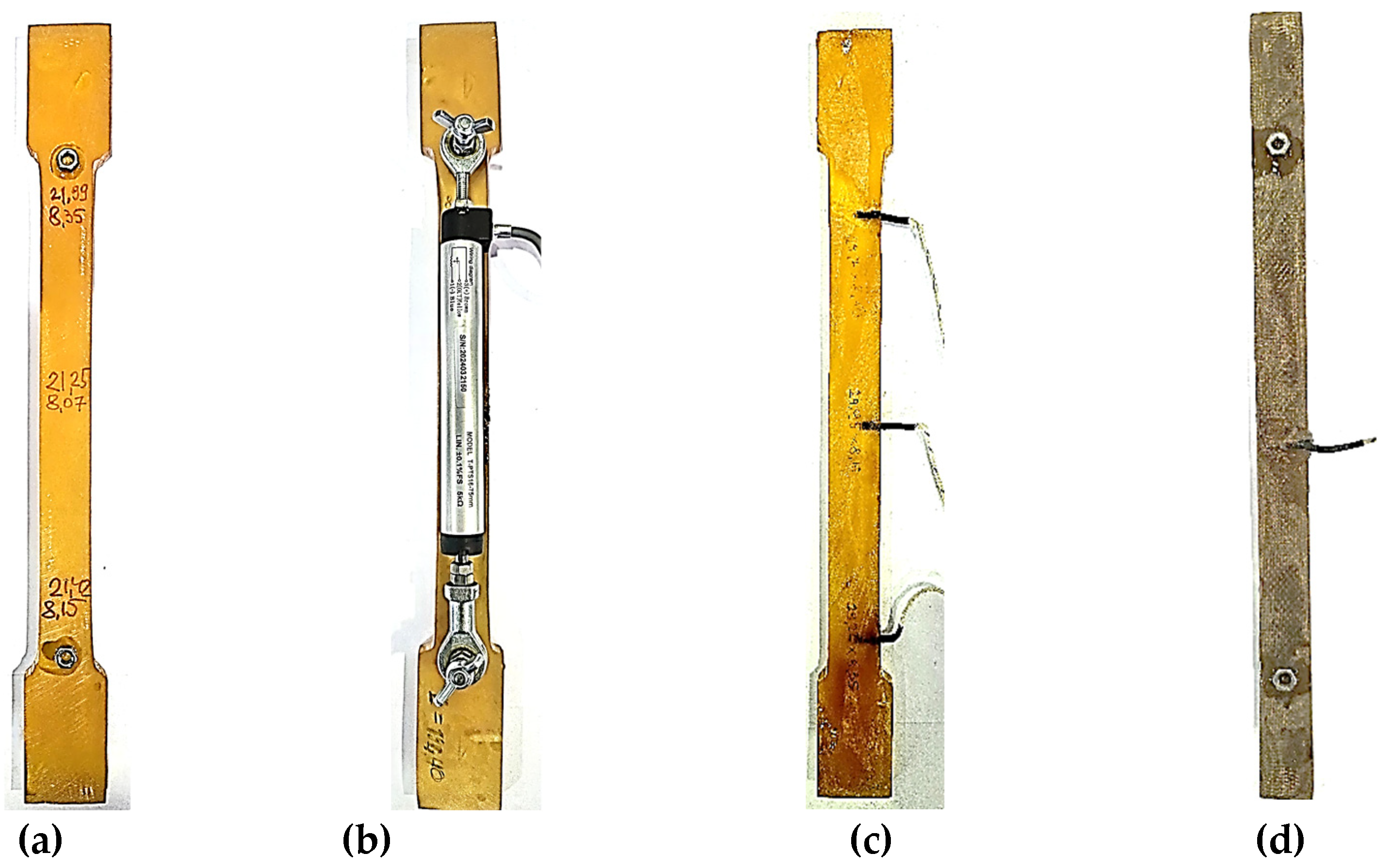
Figure 2.
Testing setup: (a) diagram; (b) general view; (c) testing process of polymer (left), glass-reinforced plastic (right).
Figure 2.
Testing setup: (a) diagram; (b) general view; (c) testing process of polymer (left), glass-reinforced plastic (right).
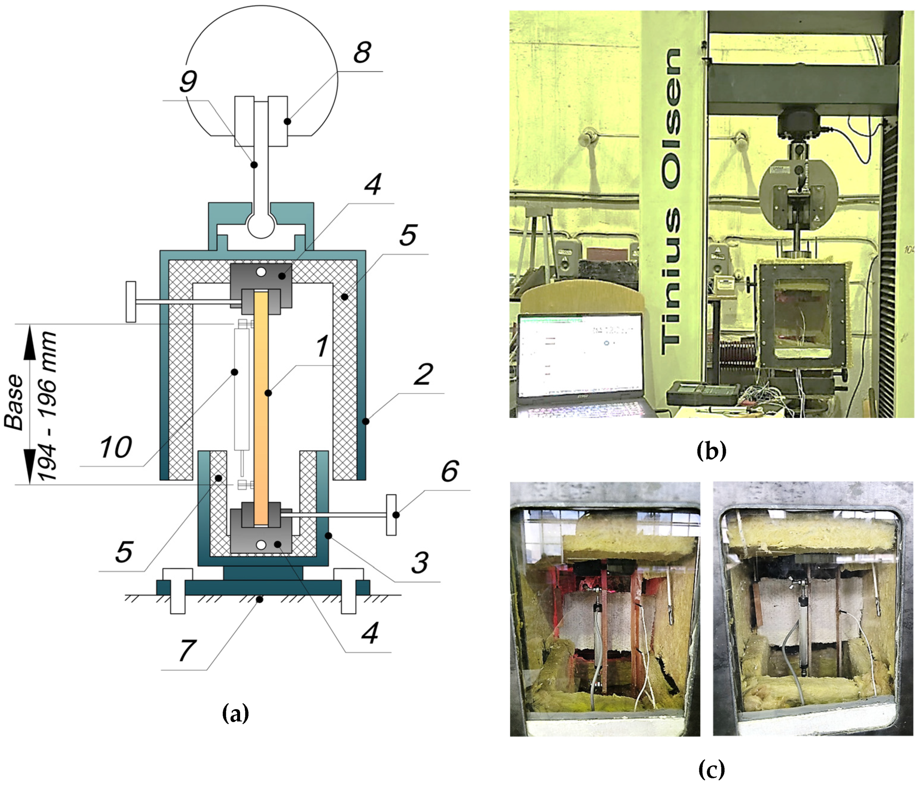
Figure 3.
Diagram of experiment stages on cyclic thermomechanical loading.
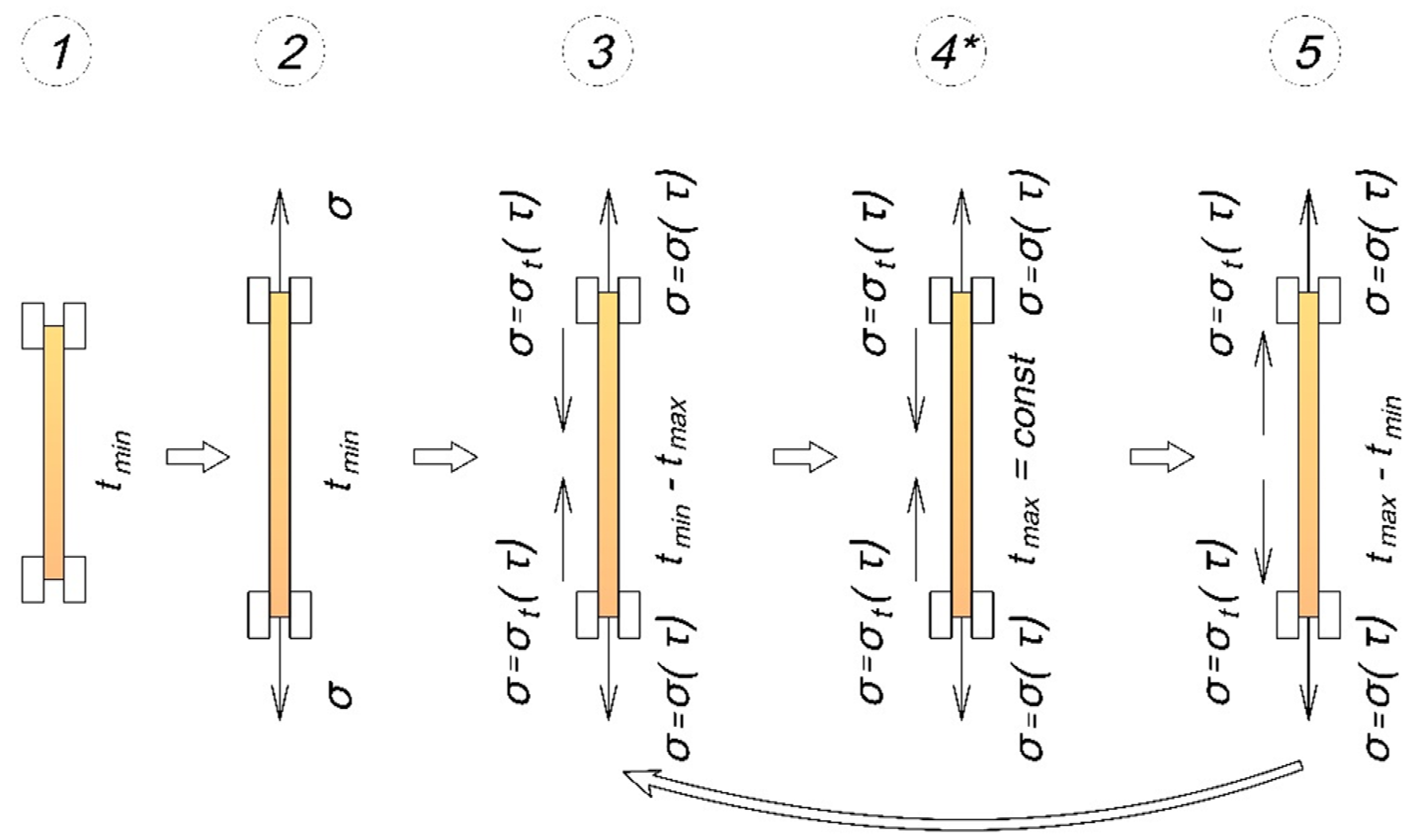
Figure 4.
Scheme of the viscoelastic three-element Kelvin–Voigt model (E1, E2 – elastic parameters, η – viscosity).
Figure 4.
Scheme of the viscoelastic three-element Kelvin–Voigt model (E1, E2 – elastic parameters, η – viscosity).
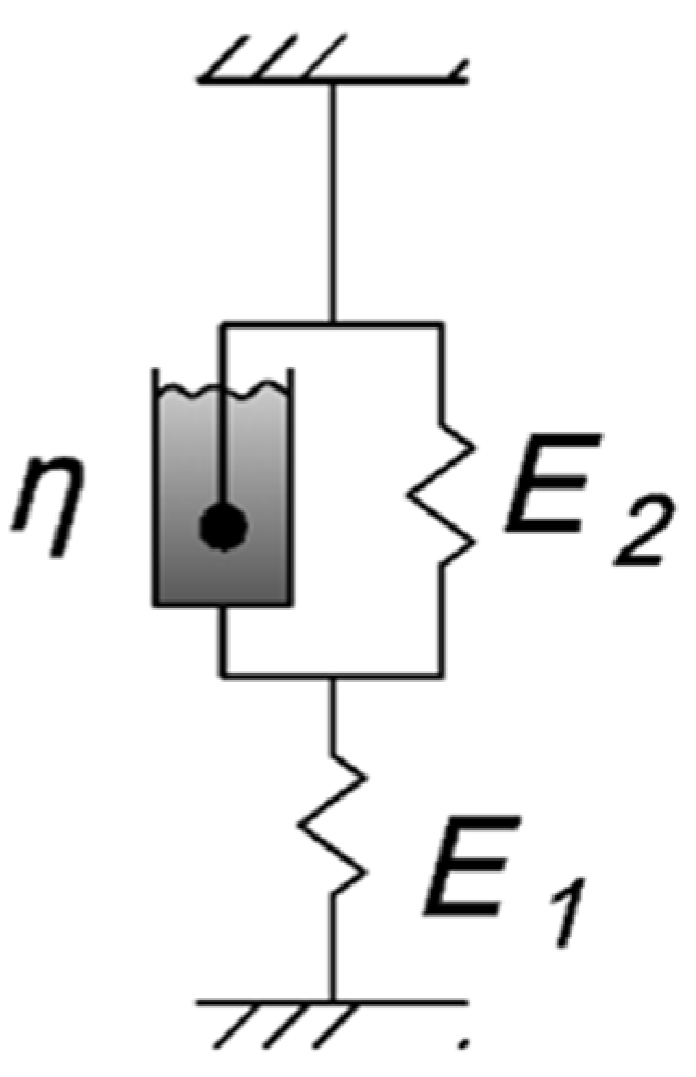
Figure 5.
Example of parameter selection for the three-element viscoelastic model on the example of relaxation of unreinforced epoxy polymer at 30°C and initial stresses of 3.95 MPa: (a) experimental and model curve; (b) parameter selection results E1, E2 and η when divided into time intervals (0–60 s, 60–120 s, 120–360 s, 360–720 s, 1800–4500 s).
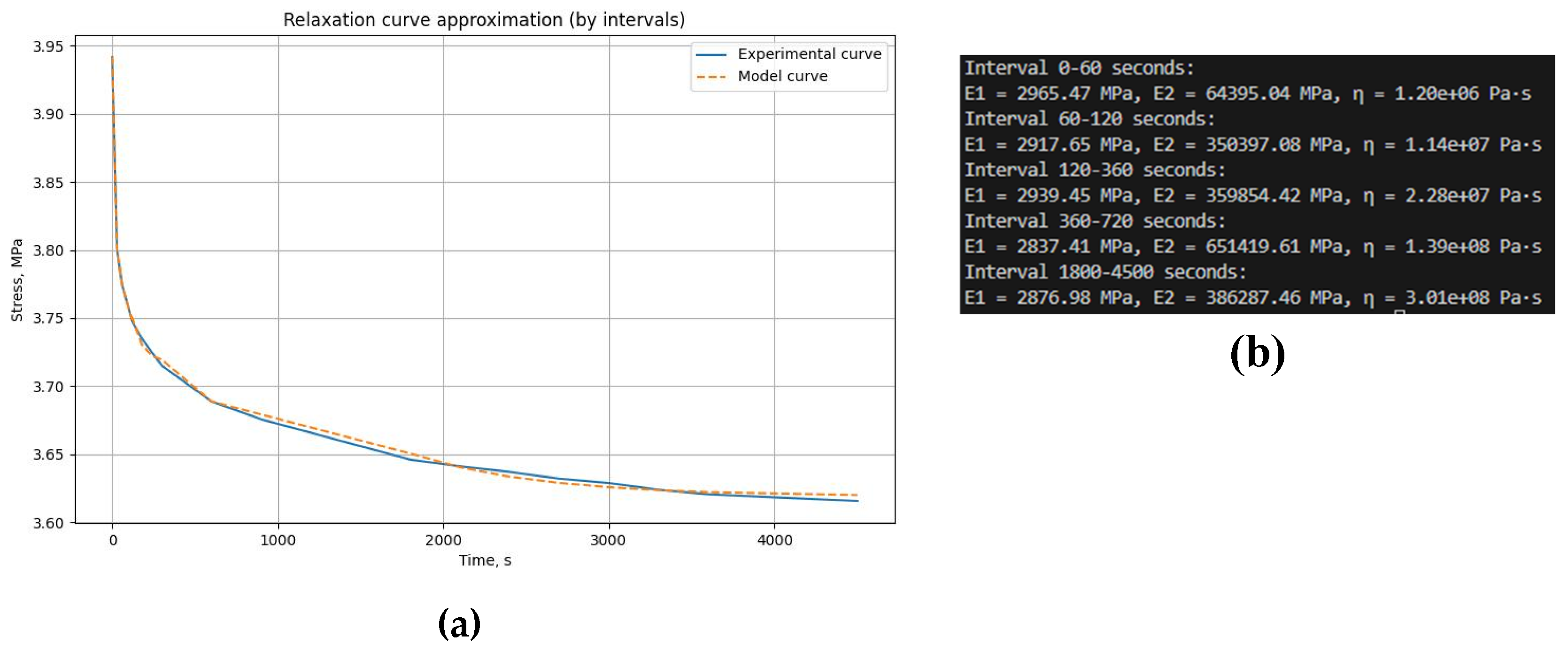
Figure 6.
Model scheme: 1 – thermal brake; 2 – cell in the form of a three-element viscoelastic model.
Figure 6.
Model scheme: 1 – thermal brake; 2 – cell in the form of a three-element viscoelastic model.
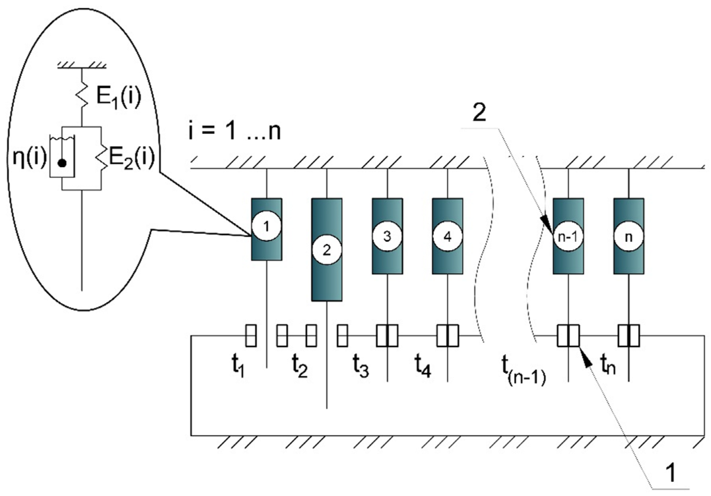
Figure 7.
Relaxation curves of the investigated epoxy polymer at temperatures of 30°C, 60°C, 90°C, and initial tensile stresses of 4.2 MPa.
Figure 7.
Relaxation curves of the investigated epoxy polymer at temperatures of 30°C, 60°C, 90°C, and initial tensile stresses of 4.2 MPa.
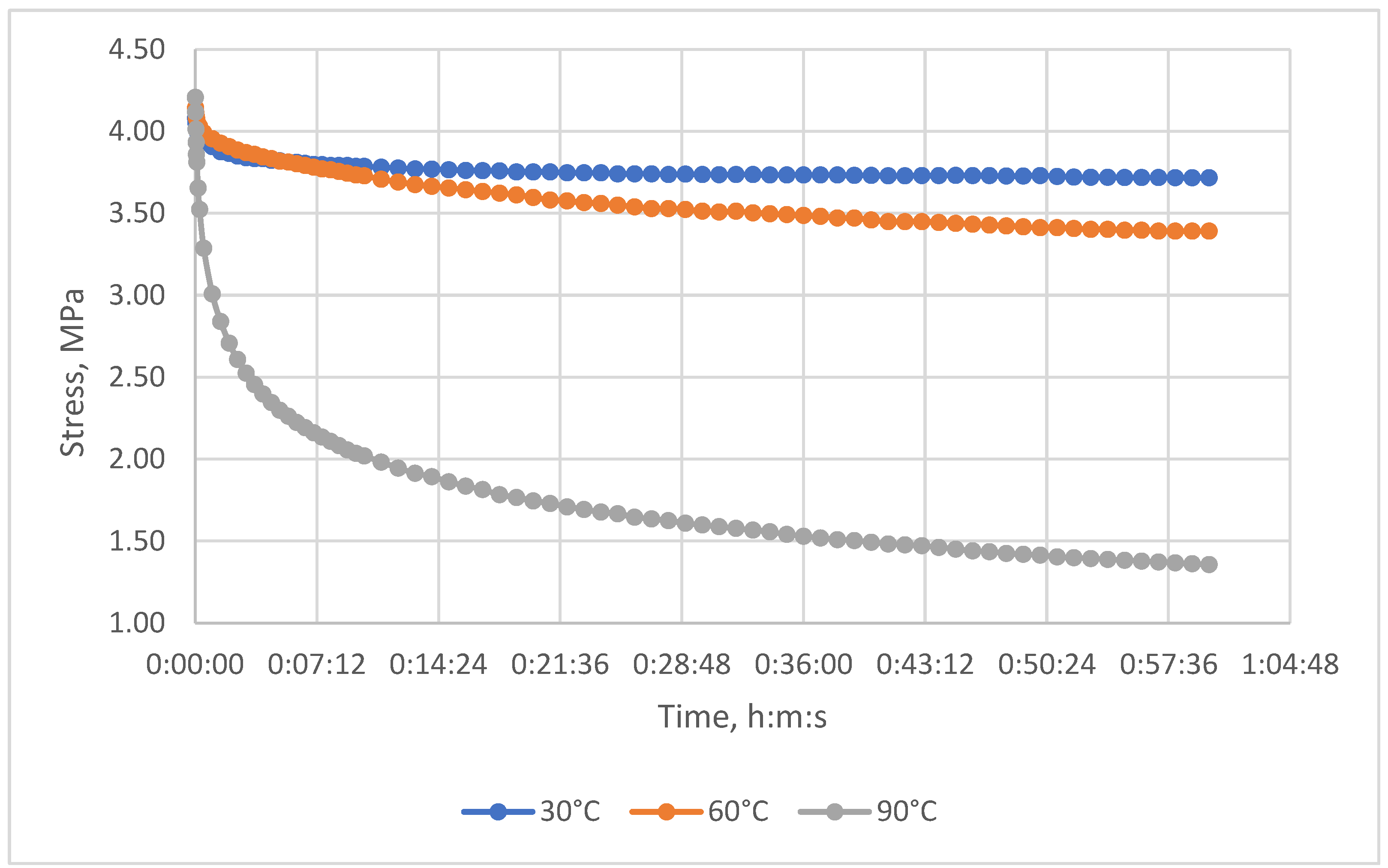
Figure 8.
Relaxation curves of the investigated glass-reinforced plastic at temperatures of 30°C, 60°C, 90°C, and initial tensile stresses of 18.4 MPa.
Figure 8.
Relaxation curves of the investigated glass-reinforced plastic at temperatures of 30°C, 60°C, 90°C, and initial tensile stresses of 18.4 MPa.
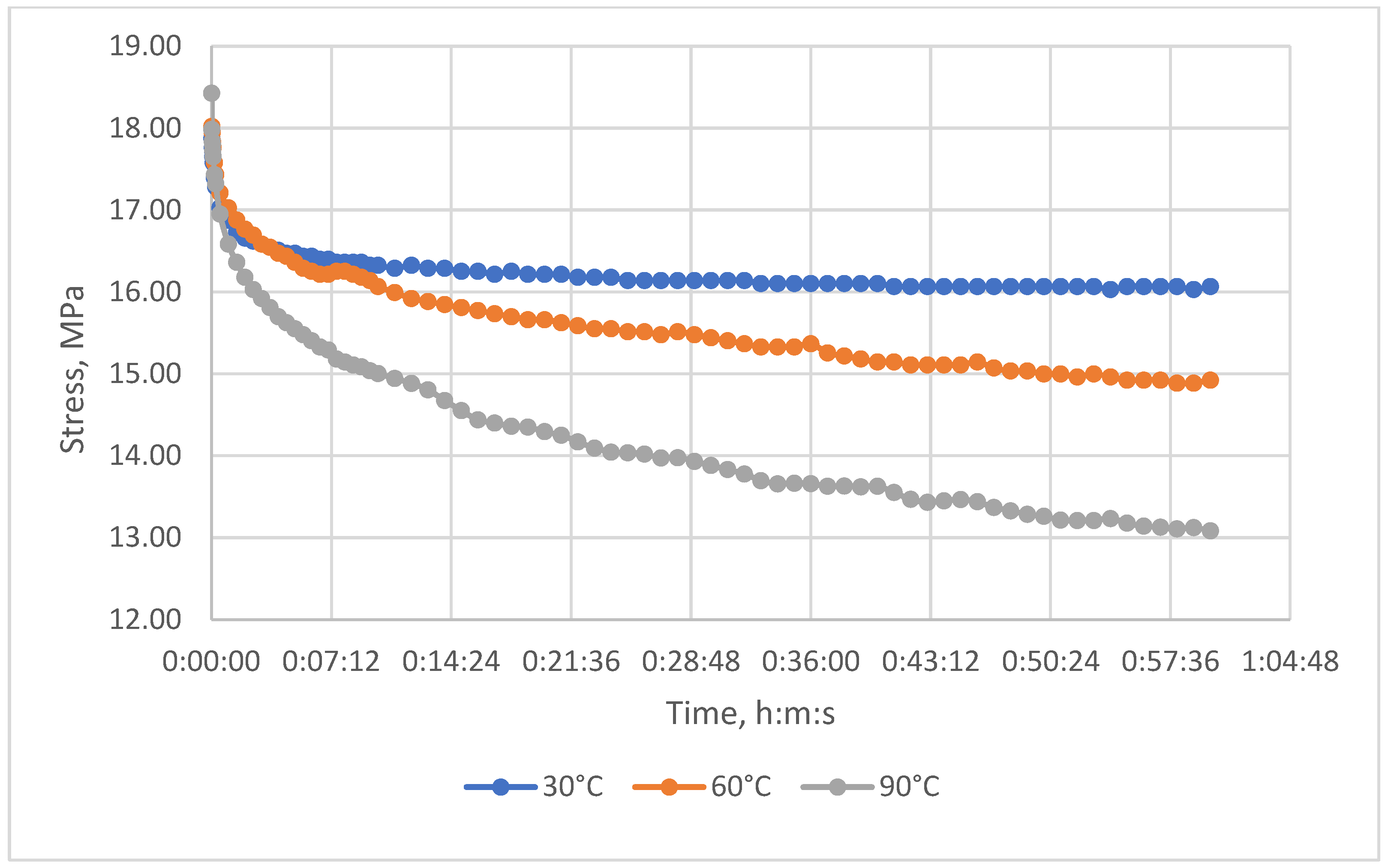
Figure 18.
Modeling and experimental results on cyclic thermomechanical loading on epoxy polymer (heating to 80°C, with holds, without applying initial tensile stresses): (a) model curves of stress changes over time during heating and cooling (blue – without considering additional residual stresses, red – with consideration).
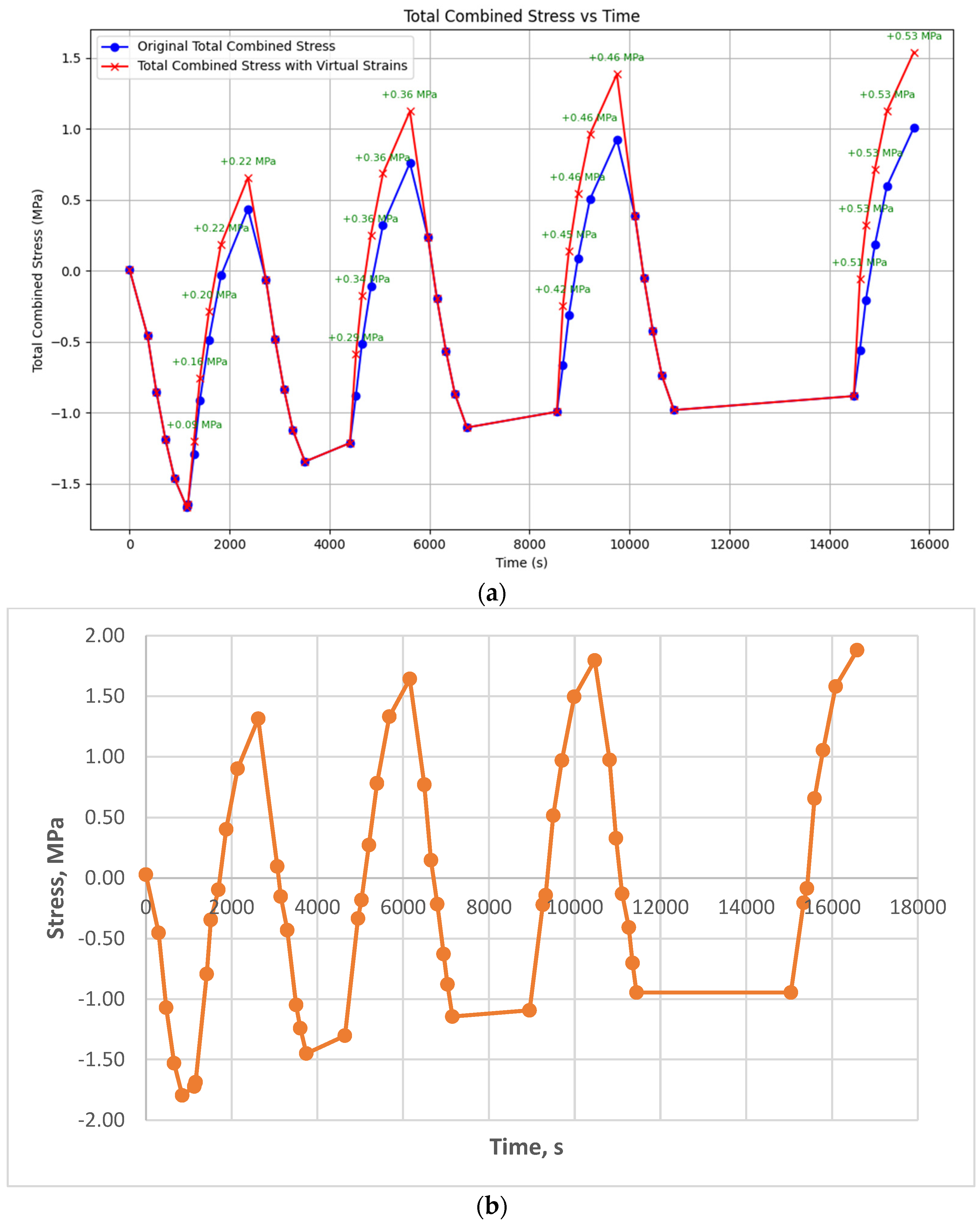
Figure 19.
Results of modeling of cyclic thermomechanical impact on epoxy polymer (heating to 90°C, without holding, initial tensile stresses 4.3 MPa): (a) curve of temperature stresses; (b) curve of mechanical stresses; (c) curves of total stresses (blue - without taking into account additional residual stresses, red - with taking into account).
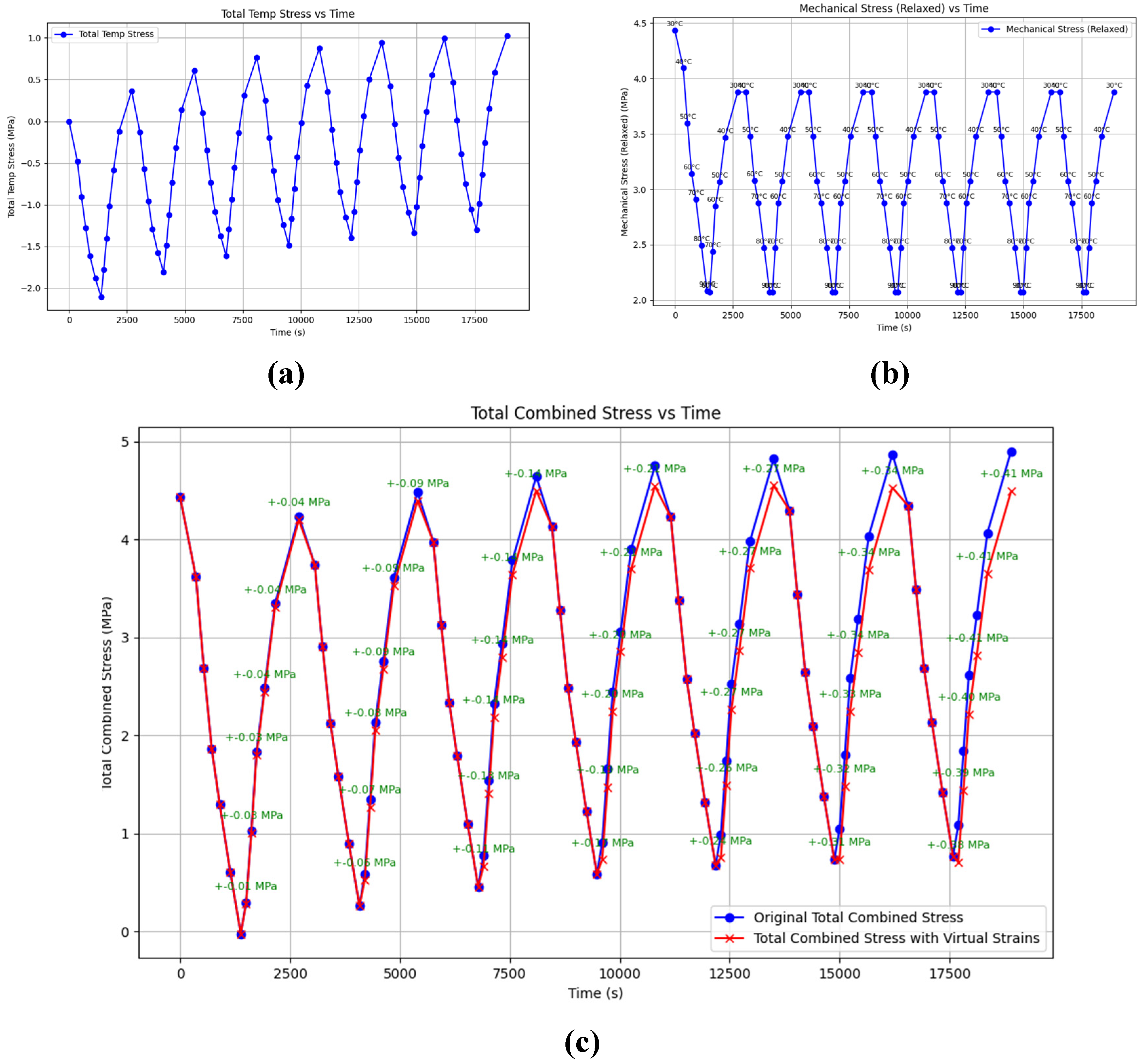
Figure 20.
Experimental results for cyclic thermomechanical effect on epoxy polymer (heating to 90°C, no holding time, initial tensile stresses of 4.3 MPa).
Figure 20.
Experimental results for cyclic thermomechanical effect on epoxy polymer (heating to 90°C, no holding time, initial tensile stresses of 4.3 MPa).
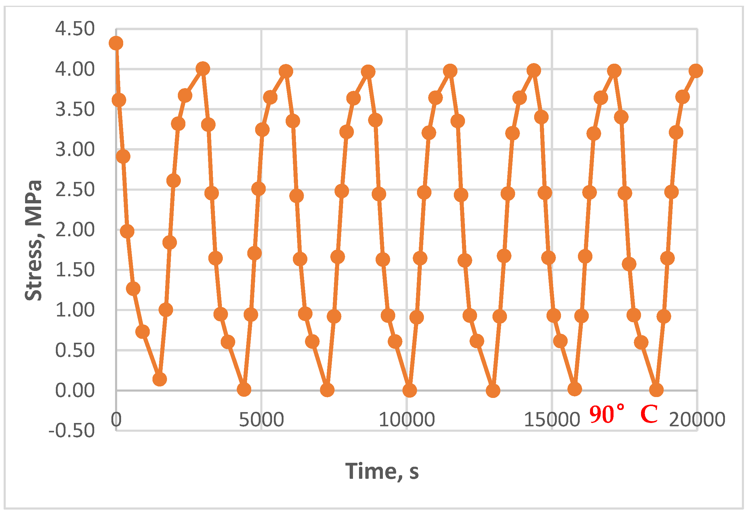
Figure 21.
Schematic description of the algorithm of the proposed model at the initial stage (a): no applied loads, initial temperature.
Figure 21.
Schematic description of the algorithm of the proposed model at the initial stage (a): no applied loads, initial temperature.
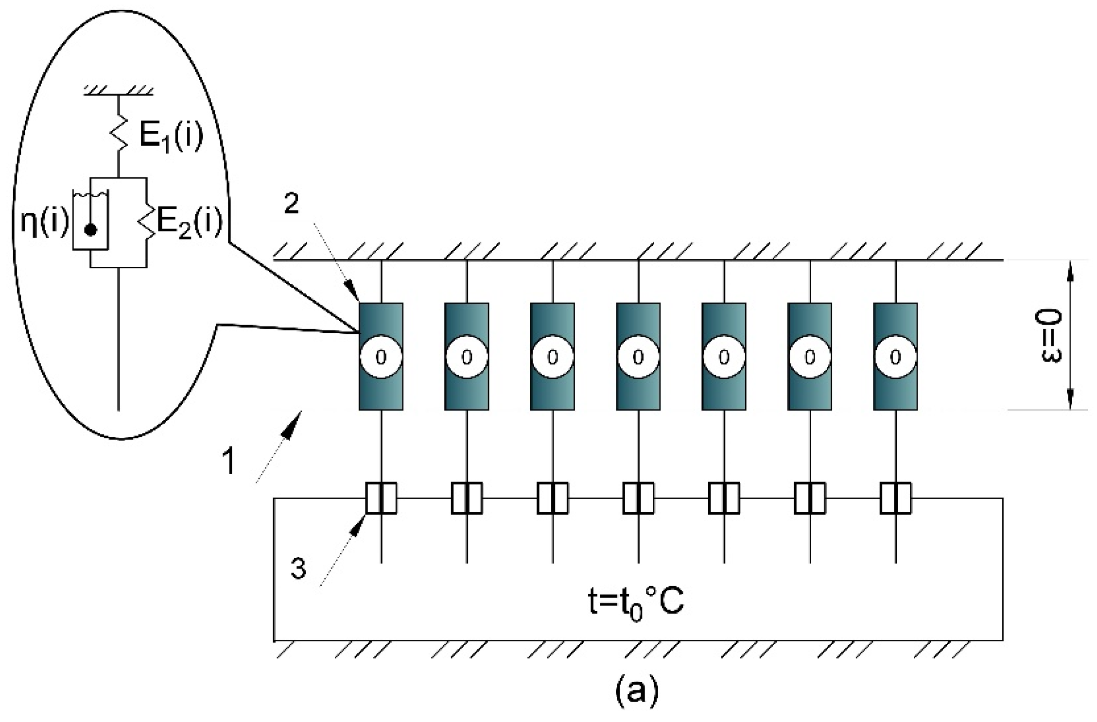
Figure 22.
Schematic description of the algorithm of the proposed model.
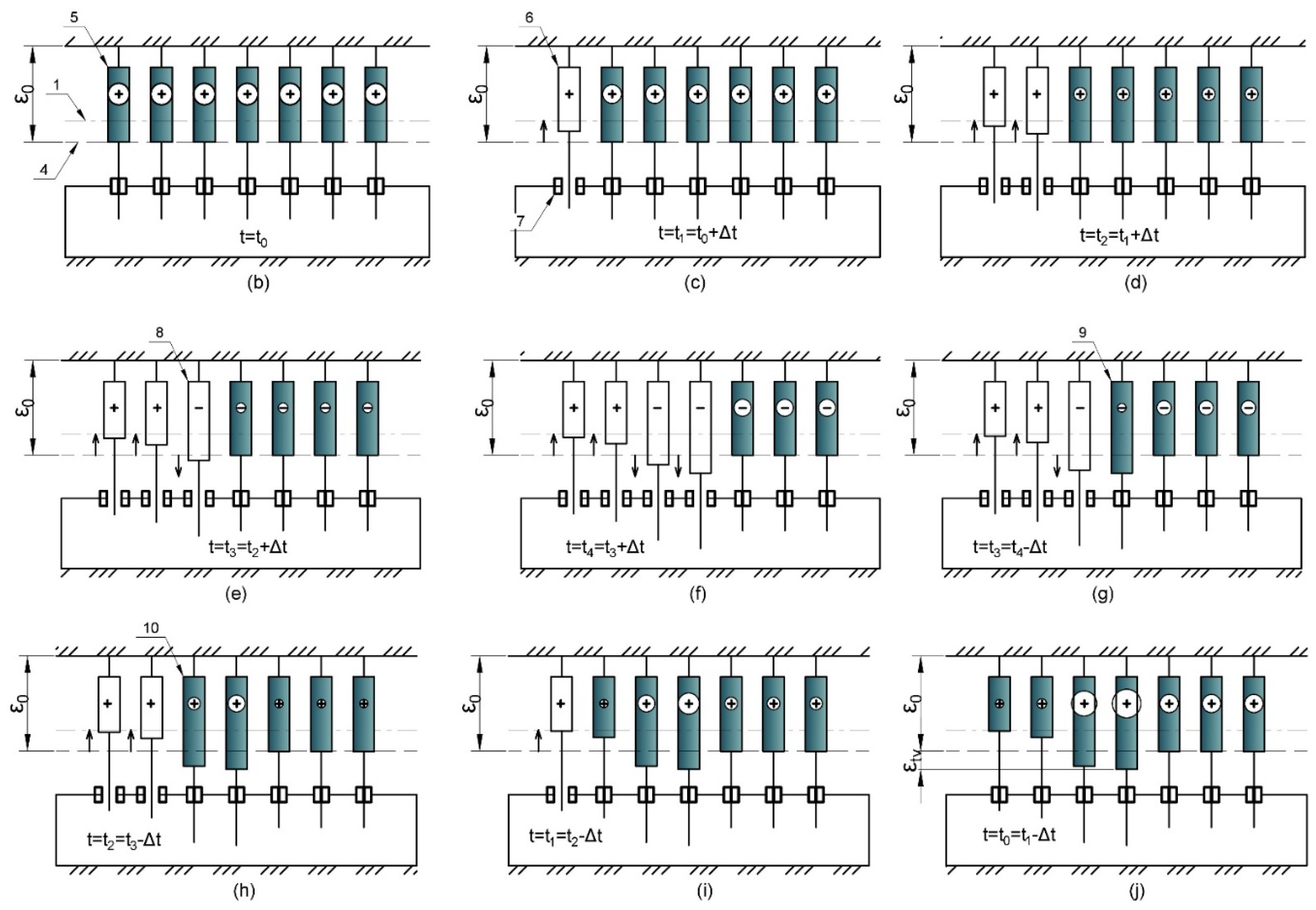
Figure 23.
Schematic of a possible improved version of the model.
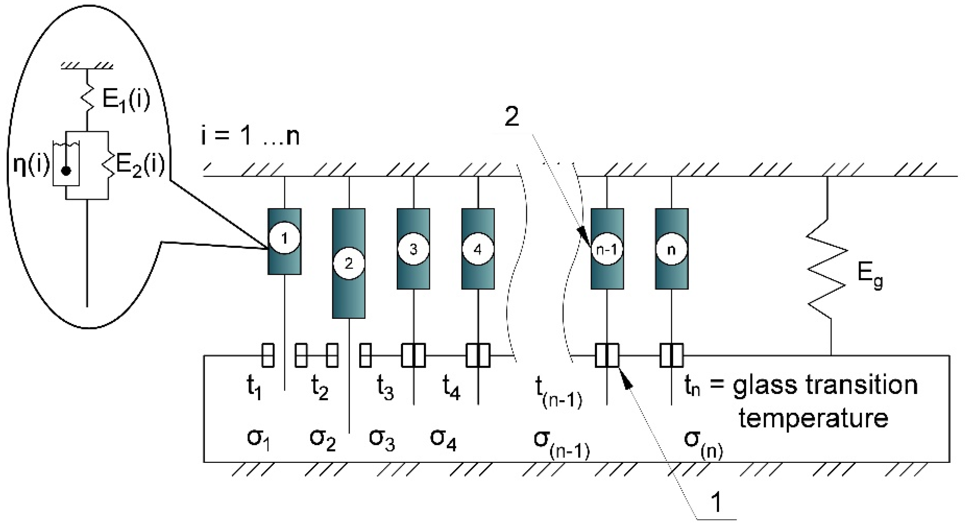

Table 1.
Results of parameter approximation E1, E2 и η based on the relaxation curve at different temperatures for the epoxy polymer at initial tensile stresses of 4.2 MPa.
Table 1.
Results of parameter approximation E1, E2 и η based on the relaxation curve at different temperatures for the epoxy polymer at initial tensile stresses of 4.2 MPa.
| Model relaxation curve | Time interval, s | E1, MPa | E2, MPa | η, MPa*s | |
|---|---|---|---|---|---|
|
t=30°C σ0 = 4.2MPa |
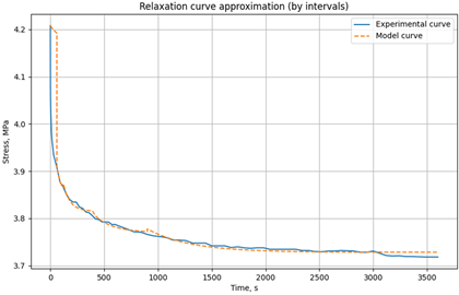 |
0-60 | 3045 | 381810 | 3.57e+07 |
| 60-120 | 3056 | 238874 | 7.40e+06 | ||
| 120-400 | 3046 | 228618 | 1.45e+07 | ||
| 400-900 | 3060 | 404890 | 6.75e+07 | ||
| 900-3600 | 3054 | 301349 | 1.20e+08 | ||
|
t=60°C σ0 = 4.2MPa |
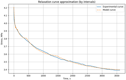 |
||||
| 0-60 | 2783 | 35982 | 1.00e+06 | ||
| 60-120 | 2761 | 194441 | 7.04e+06 | ||
| 120-400 | 2764 | 94170 | 9.87e+06 | ||
| 400-1500 | 2779 | 42637 | 2.04e+07 | ||
| 1500-3600 | 2760 | 51894 | 5.67e+07 | ||
|
t=90°C σ0 = 4.2MPa |
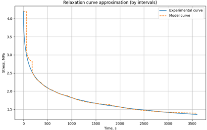 |
0-60 | 1658 | 315760 | 2.55e+07 |
| 60-90 | 1668 | 23270 | 1.00e+06 | ||
| 90-180 | 1661 | 10338 | 1.26e+06 | ||
| 180-360 | 1654 | 12222 | 2.39e+06 | ||
| 360-600 | 1658 | 13711 | 3.89e+06 | ||
| 600-1500 | 1667 | 10000 | 4.76e+06 | ||
| 1500-3600 | 1668 | 10000 | 8.63e+06 | ||
Table 2.
Results of parameter approximation E1, E2 и η based on the relaxation curve at different temperatures for the glass-reinforced plastic at initial tensile stresses of 18.4 МПа.
Table 2.
Results of parameter approximation E1, E2 и η based on the relaxation curve at different temperatures for the glass-reinforced plastic at initial tensile stresses of 18.4 МПа.
| Model / experimental relaxation curve | Time interval, s | E1, MPa | E2, MPa | η, MPa*s | |
|---|---|---|---|---|---|
|
t=30°C σ0 = 5.6MPa |
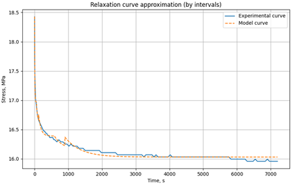 |
0-60 | 10783 | 124579 | 1.00e+06 |
| 60-120 | 10689 | 705152 | 2.20e+07 | ||
| 120-600 | 10730 | 653221 | 4.63e+07 | ||
| 600-900 | 10683 | 999732 | 2.60e+08 | ||
| 900-3600 | 10773 | 774976 | 3.64e+08 | ||
|
t=60°C σ0 = 5.6MPa |
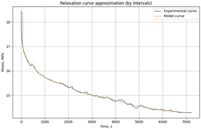 |
||||
| 0-60 | 7827 | 348725 | 1.82e+08 | ||
| 60-90 | 7833 | 317182 | 1.41e+07 | ||
| 90-180 | 7821 | 314093 | 3.64e+07 | ||
| 180-360 | 7825 | 208479 | 6.71e+07 | ||
| 360-600 | 7810 | 303202 | 1.42e+08 | ||
| 600-1500 | 7814 | 174597 | 1.97e+08 | ||
| 1500-3600 | 7832 | 139584 | 3.16e+08 | ||
|
t=90°C σ0 = 5.6MPa |
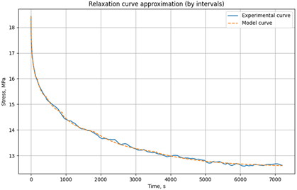 |
0-60 | 7105 | 65605 | 1.00e+06 |
| 60-90 | 7048 | 167061 | 8.48e+06 | ||
| 90-180 | 7101 | 143522 | 1.97e+07 | ||
| 180-360 | 7072 | 161122 | 4.50e+07 | ||
| 360-600 | 7091 | 128993 | 6.95e+07 | ||
| 600-1500 | 7077 | 100500 | 1.12e+08 | ||
| 1500-3600 | 7082 | 167416 | 2.67e+08 | ||
Disclaimer/Publisher’s Note: The statements, opinions and data contained in all publications are solely those of the individual author(s) and contributor(s) and not of MDPI and/or the editor(s). MDPI and/or the editor(s) disclaim responsibility for any injury to people or property resulting from any ideas, methods, instructions or products referred to in the content. |
© 2024 by the authors. Licensee MDPI, Basel, Switzerland. This article is an open access article distributed under the terms and conditions of the Creative Commons Attribution (CC BY) license (http://creativecommons.org/licenses/by/4.0/).
Copyright: This open access article is published under a Creative Commons CC BY 4.0 license, which permit the free download, distribution, and reuse, provided that the author and preprint are cited in any reuse.


