
Submitted:
12 December 2023
Posted:
13 December 2023
You are already at the latest version
Abstract
The paper presents the results of experimental studies and mathematical modeling of the effect of stress accumulation in thermosetting epoxy polymer "hot" curing on anhydride hardener. Stress accumulation occurs under cyclic thermomechanical action in a locked rod, similar effects are observed, for example, in thermoplastic elements subjected to the combined effect of mechanical loads and variable temperatures. Experimental results have shown that under cyclic thermomechanical loading during exploitation it is possible to accumulate residual stresses in the thermosetting polymer. A multi-element structural mathematical model with memory for thermomechanical load, which allows to consider the accumulation of residual thermal stresses, has been proposed. The results of modeling and experiment are compared. Based on the results, corrections are made in the approach to the application of this model to thermosetting polymers such as the epoxy resin under study. Considering the corrections, a good agreement (the difference is from 1 to 6%) with the results of experimental determination of stresses under complex cyclic thermomechanical load was obtained.
Keywords:
thermal stresses
; residual stresses
; viscoelasticity
; epoxy polymers
; fiberglass plastics
; structural model
1. Introduction
In structures and products made of polymeric materials, specific effects are observed due to the inelastic nature of their deformation during cyclic heating and cooling in conditions of strain constraint. An important role here is played by the presence of the memory of temperature prehistory associated with the so-called "freezing" deformation, which appears when the temperature decreases in the element, which is simultaneously subjected to mechanical loading. As a result, internal residual stresses are formed, which change during service and affect the performance of the structure.
Since the 1970s many researches have been carried out and a large number of works have been published, considering the problems of residual stress formation in thermosetting and thermoplastic polymers and polymer composites, as usual, it is about residual technological stresses formed during the manufacturing of products.
The main reasons and mechanisms of formation of residual temperature stresses in polymers and composites are summarized in monographs[1,2,3,4,5,6], review and research publications [7,8,9,10,11]. These include temperature gradients along the thickness of structures, different (including anisotropic) thermal expansion of polymer composites components, features of technological modes of curing, chemical shrinkage of polymer matrix, interaction with technological tools and others.
Problems on prediction of residual stresses can be solved in different statements, for example, in the work of 1976 [7] the problem of determination of thermal and moisture residual stresses in a layered polymer composite was solved in an elastic statement without considering the viscoelastic properties of materials. At the same time, most other works on predicting residual stresses in polymers and composites necessarily consider the viscoelastic properties of at least the polymer matrix.
A paper from 1978 [12] is devoted to the study of residual thermal stresses in homogeneous (unreinforced and unfilled) amorphous polymers formed on the history of thermomechanical loads. Here the principles of formation of frozen deformations and stresses are described, the approaches of elasticity and viscoelasticity theory are applied for their prediction, and the effects of macromolecule orientation are considered.
In 1996 [13] , a procedure for calculating residual thermal stresses during a step-by-step non-isothermal cooling cycle in composite products with a polymer matrix considering its viscoelastic properties was proposed.
To the present day, the topic under consideration has not lost its relevance, as evidenced by many modern works.
For example, in the 2005 paper [14] , the finite element method using the well-known viscoelastic Maxwell model [15] is used to determine the stresses (including residual stresses) in a glass-like material.
In a 2016 paper [16] the problem of calculating the residual stresses in polymer matrix composites appearing during the curing process is solved. For different material states at different stages, the problem is solved in an elastic or viscoelastic formulation.
The papers of 2016, 2018 [17,18] presented an approach using multiscale finite element modeling to describe the viscoelastic-plastic behavior of unidirectional composites with polymer matrix and to predict the forming of residual thermal stresses during curing.
The study of polymers and composites with shape memory is a very relevant topic at present. The shape memory effect is also associated in many details with the existence of relaxation transitions in polymers, viscoelastic thermo-dependent properties, forming frozen deformations and the stresses induced by them. Therefore, there are many works in this field on experimental investigation and modeling of viscoelastic behavior of thermosetting and thermoplastic polymers. For example, the review paper [19] illustrates the current state of the art in the field of structural models of polymeric materials that allow modeling viscoelastic processes (creep, relaxation) and the transfer through the glass transition temperature. This paper describes 19 structural viscoelastic models, each of which has its own specific features.
The above-mentioned works are mainly related to the fields of mechanical engineering, automotive engineering, aerospace engineering and even medicine, while the works devoted to building structures from polymer composites are relatively few, and the problems of accumulation of thermal stresses in them in the process of long-term operation at variable temperatures - even less. The operation of building structures from polymer composites will have its own specific features, on which it is necessary to be focused.
The temperature-time dependence of the mechanical properties of plastics causes a specific change in the stress state of the element with constrained strain during heat changes, which is detected experimentally [12,20,21] and which manifests itself in the accumulation of residual stresses, the external appearance of which, for example, can be a network of cracks in the polymer matrix. The reason for the appearance of internal stresses are unrealized thermal deformations, and their evolution and accumulation are caused by the interrelated processes of creep and relaxation, the rate of which varies with temperature and loading level. One consequence is that residual stresses in a structure can occur not only during fabrication and then evolve throughout the service life. For example, they can accumulate in individual elements of polymer composite structures during repeated heating and cooling cycles. Building structures where such effects occur include, for example, chimneys and gas ducts made of polymer composites [22,23,24,25].
To predict the viscoelastic behavior of polymers and composites under cyclic thermomechanical loading, we propose an approach using a structural multielement model, which was presented and described in[21]. Experimental verification of this model was carried out on the example of a biplastic structure with an inner layer of thermoplastic polymer - unplasticized polyvinyl chloride, the results of predicting residual thermal stresses in PVC were satisfactory [26].
The present work is mainly aimed at obtaining in the future the results necessary for the design of large-size shell structures made of polymer composite materials used in gas exhaust ducts of industrial enterprises. At this stage the object of research was an epoxy polymer on anhydride hardener, widely used as a matrix for winding fiberglass structures of chimneys and gas ducts. Unlike polyvinyl chloride, which is a thermoplastic, epoxy resin belongs to thermosetting polymers. Therefore, the application of the proposed model is novel in this case.
In the future, the proposed approach (described in detail below, in the Materials and Methods section) is planned to be extended to reinforced composites with a matrix of thermosetting polymers.
The main objectives of the present work were:
- -
- determination of mechanical parameters of the investigated epoxy polymer for the viscoelastic structural model of Kelvin-Voigt;
- -
- development of methodology and experimental studies of the stress state of the investigated polymer under the combined action of static mechanical load and cyclically changing temperature;
- -
- implementation of the calculation algorithm using the proposed approach in the MathCAD 14 Academic computational package and comparison of the results of modeling the stress state of the sample with the experiment.
2. Materials and Methods
2.1. Materials
Experimental studies were carried out on rod samples made of hot-curing epoxy resin on anhydride hardener with the addition of a curing booster.
The following materials were used for manufacturing the experimental specimens:
- -
- KER 828 epoxy resin: epoxy group content (EGC) 5308 mmol/kg, equivalent epoxy weight (EEW) 188.5 g/eq, viscosity at 25ºC 12.7 Pa×s, HCl 116 mg/kg, total chlorine 1011 mg/kg. Manufacturer: KUMHO P&B Chemicals, Seoul, Korea.
- -
- Isomethyltetrahydrophthalic anhydride (IZOMTGFA) (hardener for epoxy resin): viscosity at 25ºC 63 Pa×s, anhydride content 42.4%, volatile fraction content 0.55%, free acid 0.1%. Manufacturer: ASAMBLY Chemicals Company Ltd., Nanjing, China.
- -
- Alkophen (epoxy curing booster): viscosity at 25°C 150 Pa×s, molecular formula C15H27N3O, molecular weight 265, amine number 600 mg KOH/g. Manufacturer: JSC "Epital", Moscow, Russian Federation.
One epoxy binder composition was used with the following mass ratio of components:
- -
- Epoxy resin (KER 828) - 52.5%.
- -
- Hardener (IZOMTGFA) - 44.5%.
- -
- Curing booster (Alkophen) - 3%.
The binders were mixed using a Stegler DG-360 mechanical dispersant-homogenizer (China) with a 17 mm diameter M-shaped nozzle with a nozzle rotation speed of 6000 rpm/min. After mixing, the binders were poured into silicone molds and placed in a laboratory oven for curing. The samples were cured at 110°C for 30 min. After initial curing, all samples were held at 150°C for 12 hrs. After curing and holding, the core specimens were cut from the resulting plate and their surface was further smoothed using an emery wheel. The average size of the specimens after machining was 205 x 20 x 9.5 mm. A photo of the specimens is shown in Figure 1.
2.2. Methods
2.2.1. Methods of experimental research
2.2.1.1. Description of the experimental setup
In the process of this work, basic tensile tests combined with cyclic heating and cooling were carried out during experimental investigations. The purpose of these tests was to investigate the change in the stress state of the specimen with time as a result of thermomechanical loading, creep and relaxation. In addition to the basic tests, the experimental determination of viscoelastic mechanical parameters of the tested specimens was necessary for subsequent modeling.
Tensile tests in combination with thermomechanical loading, as well as the determination of viscoelastic characteristics were performed on a Tinius Olsen h100ku tensile machine (Horsham, USA) in a specially designed and manufactured thermo-chamber.
According to the producer's data for a Tinius Olsen h100ku machine, the load accuracy was ± 0.5% in the range 0.2-100% of the installed force sensor (100 kN). The resolution of measuring the crosshead movement was 0.1 mm, with an error of up to 0.01 mm. The sample center point displacement under the load was monitored by a mechanical di-al gauge mounted on the bottom of the small-sized test chamber. This monitoring was aimed at excluding the machine compliance influence. The difference between the dis-placement readings along the traverse and the dial gauge did not exceed 2%.
The scheme and photo of the fabricated thermal chamber are shown in Figure 2. The scheme shows a rod sample 1 clamped in internal clamps 4. The thermal chamber consists of an upper movable part 2 and a lower fixed part 3, rigidly bolted to the fixed base 8 of the Tinius testing machine. The upper part 2 of the thermal chamber is in a suspended state, it is clamped in the upper clamp of the Tinius testing machine by a hinged rod 10. The upper 2 and lower 3 parts are not in contact, which allows free deformation of the specimen 1 clamped in the inner clamps 4. Crimped angle supports 7 are installed on the specimen 1, on which the feet of displacement indicators are installed, which will allow, by analogy with extensometers, to measure deformations of the specimen at a fixed length (base) and to exclude the influence of slipping of the specimen in the grips.
The thermal chamber is thermally insulated from inside with mineral wool plates0 and equipped with heating elements and a fan designed to provide uniform heating when the heaters are on and cooling when the heaters are off. The temperature in the chamber is regulated by a thermostat based on the temperature sensor inside the chamber. During testing, the temperature in the specimen is also controlled by an additional thermocouple, which is installed inside a similar epoxy specimen placed next to the specimen being tested.
Although the thermal chamber described above is not industrially manufactured, it allows tensile and compression testing at elevated temperatures with good accuracy. The accuracy of the specimen load measurement is ensured by the sufficient sensitivity of the Tinius testing machine, because (unlike, for example, industrial DMA analysis instruments) the unit is designed for testing relatively large-sized specimens, which requires less sensitive equipment, since the tests are carried out at relatively high loads and is more suitable for the study of building structures with large dimensions.
2.2.1.2. Description of the methodology for determining the mechanical characteristics of samples
The theoretical approach described below, and the proposed structural model are based on the use of a three-element viscoelastic material structural model (Figure 3), known in the literature as the Kelvin-Voigt model [15].
The strain law described by this model is as follows:
here E=E1, , . The coefficient E represents the instantaneous elastic modulus, H is the long-term elastic modulus, and n is the relaxation time.
In determining the parameters of the Kelvin-Voigt model, tensile tests were carried out on the specimens at a constant temperature of 30°C. The tests were carried out as follows: a constant tensile load of 1800 N was applied to the specimen placed in the thermal chamber and heated to 30°C, after which the load was reduced because of stress relaxation in the specimen. The displacements of the specimen within the base at the moment of loading were recorded by indicators to determine the parameter E1 (instantaneous modulus of elasticity).
To determine the mechanical parameters, equation (1) is transformed to the form:
where ε - strains, σ - stresses, τ - time.
Figure 4.
Relaxation curve of an epoxy sample for the determination of viscoelastic parameters.
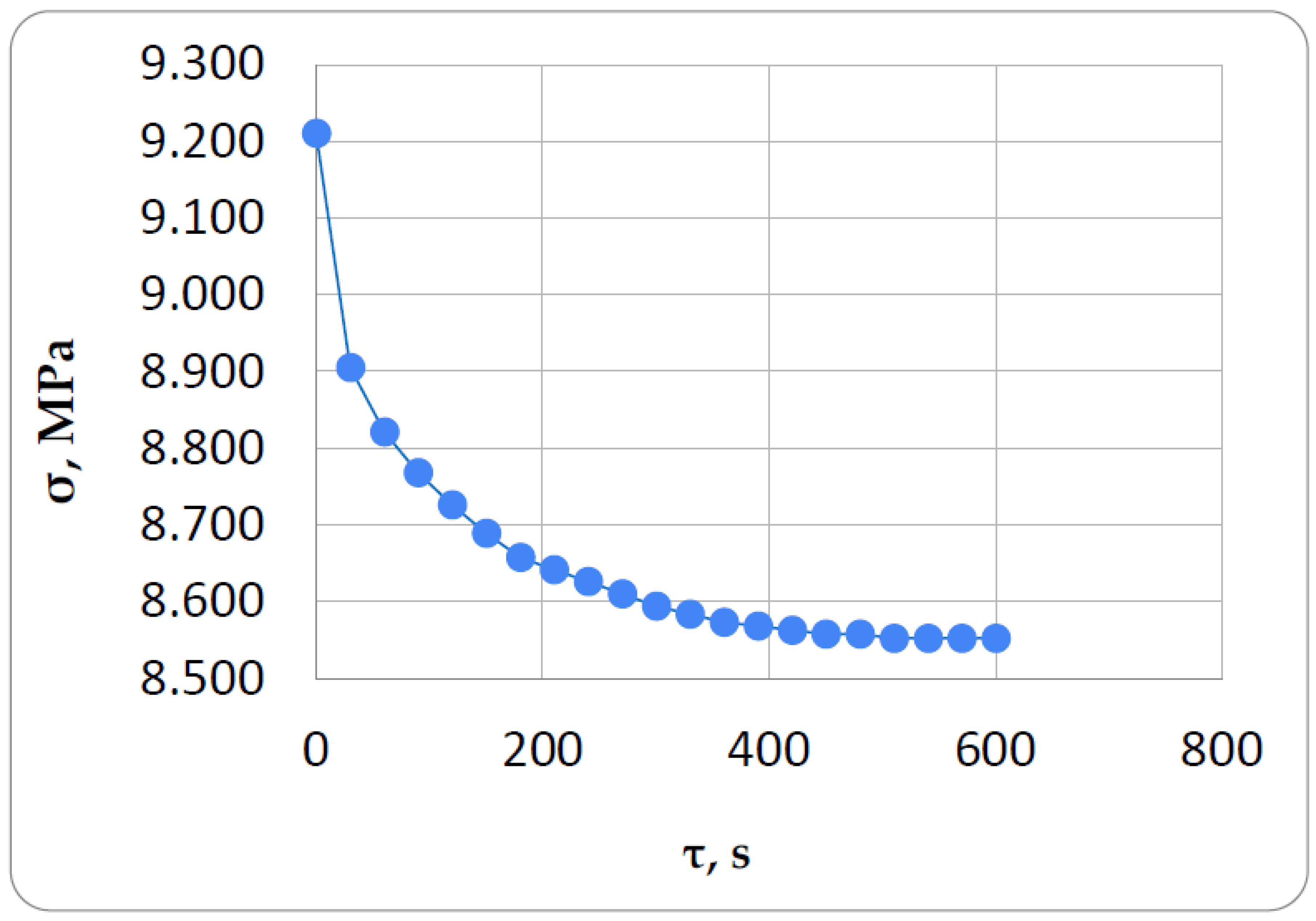
The problem of determining the mechanical parameters for the Kelvin-Voigt model is solved in MathCAD. For this purpose, arrays of stress values and time to which these stresses correspond are entered into the package. The values of the required parameters E2, η (E1 is known to us) are set in the first approximation, the system of exponential equations is solved numerically and the final values of E2, η are selected. It should be noted that since the solution is carried out by numerical method, not always the values of parameters E2, η obtained as a result of the solution together with the given E1 describe a curve close to the experimental one. Therefore, by varying the initial values of the parameters and changing the amount and numbers of points for which the solution is obtained, we must achieve the best visual match between the experimental curve and the curve calculated in MathCAD (Figure 5). The parameters that provide the best visual coincidence of the curves are taken as parameters of viscoelastic deformation of the material under study and are further used for modeling of cyclic thermomechanical loading.
2.2.1.3. Description of the methodology of the experiment on cyclic thermomechanical loading
The cyclic thermomechanical loading experiment consisted of the following steps (Figure 6):
- The epoxy rod specimen with pre-installed angle crimps is clamped in the internal clamps of the setup described in Section 2.2.1.1. The thermal chamber and the specimen installed in it are heated to an initial constant temperature of 30°C.
- An initial tensile load of 1800 N (stress 9.211 MPa) is applied to the specimen, and displacements within the base are recorded on the indicators for the reference determination of the instantaneous modulus of elasticity E1. The speed of movement of the gripper of the testing machine is 5 mm/min. After the load is reached, the clamps remain in the same position and the deformation of the specimen from the mechanical load does not change, while the load starts to decrease because of relaxation.
- At the moment the load of 1800 N is reached, the heating mode of the specimen is activated. The specimen is heated to 100°C in 8 min (heating rate is 0.1459°C / s). During heating, the specimen starts to expand and, since it is rigidly fixed in the clamps, compressive thermal stresses start to increase in the specimen, which are superimposed on the tensile mechanical stresses and reduce them, which is reflected in the stress-time curve.
- At the moment when the temperature on the control thermocouple reaches the value of 100°C, the sample cooling mode is switched on. The sample is cooled from 100°C to 30°C in 16 min (cooling rate is 0.073°C / s). On heating, the specimen begins to shrink and the compressive temperature stresses that were generated during heating are reduced in the specimen.
- The heating and cooling cycles of the specimen are repeated the required number of times and the load values on the force gauge of the testing machine corresponding to the peak temperature values are recorded.
The testing process is shown on the Figure 7.
The scheme of tests, in which the specimen is pre-stretched by mechanical load, was chosen firstly to keep the specimen in the stressed state during heating, which allows to avoid overlapping errors from backlashes in the testing equipment, and secondly it was interesting to evaluate the accuracy of the proposed methodology in this complex type of stressed state, when relaxing tensile stresses are combined with changing sign and also relaxing temperature stresses.
2.2.2. Methods of theoretical research
The proposed structural model of polymer material is multielement, it consists of a number of parallel connected elementary cells, each of which represents the Kelvin-Voigt model described above with the same elastic and viscous elements for all cells. The main feature that differs it from other models known to us is that each cell is equipped with a temperature brake that operates at a certain temperature and turns the cell on or off from operation. The cells are switched off when the temperature rises and switched on when it falls, and after switching off the cell, which is in a stress-strain state, does not disappear, but continues to work according to the law of inverse creep. This makes it possible to model the "memory" effect.
The change with temperature of elastic and rheological properties is described only by the change in the number of working cells having the same mechanical parameters, which allows them to be simply identified and specified. In our work we divide each of the mechanical parameters of the material (E1, E2, η) by the number of cells into which the model is divided. Thus, we obtain a linear dependence of mechanical properties on temperature, but nonlinearity can be considered if we switch cells not one by one, but several pieces in accordance with the dependence of mechanical characteristic on temperature. In this case, the number of cells should be sufficiently large. There are other possibilities to consider nonlinear dependencies, for example, by adding relevant coefficients, but we do not consider them at this stage. In the proposed formulation the model can be applied only at temperatures below the glass transition temperature of the material.
Under thermal influence, the model works as follows. The strain ε0 unrealized in the temperature increment step creates stresses σ in the unit cell, which further relax in time τ according to the law [15]:
где E1 , E2 – elastic parameters of the material, η – viscosity parameter, H=E1E2/(E1+E2) - long-term modulus, m=η/(E1+E2).
After turning off a cell at time τ*, i.e., after the brake is applied, the stresses are redistributed to other working cells, and the strains in the cells change according to the inverse creep law (we can call this strain virtual):
In this case, the stresses in the turned-off cell become equal to zero, the elastic deformation εe, before the moment of brake operation, instantly becomes equal to zero and by absolute value passes into the slip deformation εs, and the viscous (rheological) component of the deformation εr changes in time, changing εs, so that the total deformation at the step ε, equal to the unrealized value of the non-thermal deformation, remains constant.
When the temperature drops to a certain value, the turned off cells are turned back on, and the virtual strains that were growing in the turned off state will turn into stresses and will be summarized with mechanical and thermal stresses evenly distributed among the turned on cells. At the same time, in each switched-on cell the stresses from frozen strains will be different because their switching on and off occurs at different temperatures at different moments of time. The accumulated stresses caused by virtual deformations will be the residual stresses formed as a result of cyclic thermomechanical loading.
Thus, if after reaching a certain elevated temperature, the rod is cooled down, the forced-elastic deformations that arose during heating of the rod are gradually "frozen". When reheating, the "frozen" forced-elastic deformations gradually unfreeze as the temperature rises, as if partially compensating for the thermal deformations of the rod. The stress curve in this case does not coincide with the stress curve of initial heating. As the working temperature of rod heating approaches the glass transition temperature of the polymer, the compressive stresses during heating decrease after reaching some maximum, and the level of residual tensile stresses after cooling increases.
Real structures in their whole or in localized regions can be viewed as a system of constrained rods, the flexibility of the constraint of which is determined by the design features of the product. Even if the structure is completely homogeneous, local heating or cooling of its part causes the processes we consider for a constrained rod.
The scheme below shows the application of the proposed model in the conditions of our experiment described in Section 2.2.1.3 above. In the scheme, the model is divided into five cells; in real calculations, we divided it into 12 cells.
The first stage of the experiment is shown at Figure 8:
- -
- 1.A: initial stage at zero time at initial temperature and zero stresses.
- -
- 1.B: a mechanical tensile load is applied (the time of load increase is not taken into account), mechanical stresses are evenly distributed among all cells, the strain of the specimen has increased to ε0, the temperature is also equal to the initial one.
- -
- 1.C: heating starts, compressive thermal stresses appear, all cells are included, mechanical and thermal stresses are evenly distributed among all cells, thermal stresses reduce mechanical stresses.
The second stage (heating) of the experiment is shown on the Figure 9:
- -
- 2.A: The shutdown temperature of the first cell is reached, it is off and deforms according to the inverse creep law (4), before shutdown the cell was stretched, after shutdown virtual compressive deformations grow in it;
- -
- 2.B, 2.C: the same as in 2.A, but with subsequent cells, in the end there are several working cells.
The third stage (cooling) of the experiment is shown on the Figure 10:
- -
- 3.A: Cooling is in progress, temperature stresses have changed sign and coincide in direction with mechanical tensile stresses, the switching temperature of the cell that was turned off last has been reached, it is turned on and strains in it turn into stresses.
- -
- 3.B, 3.C: the same as in 2.A, but with subsequent cells, eventually the initial temperature is reached and all cells are turned on, with each having contributed a different value of the residual stresses at turning on.
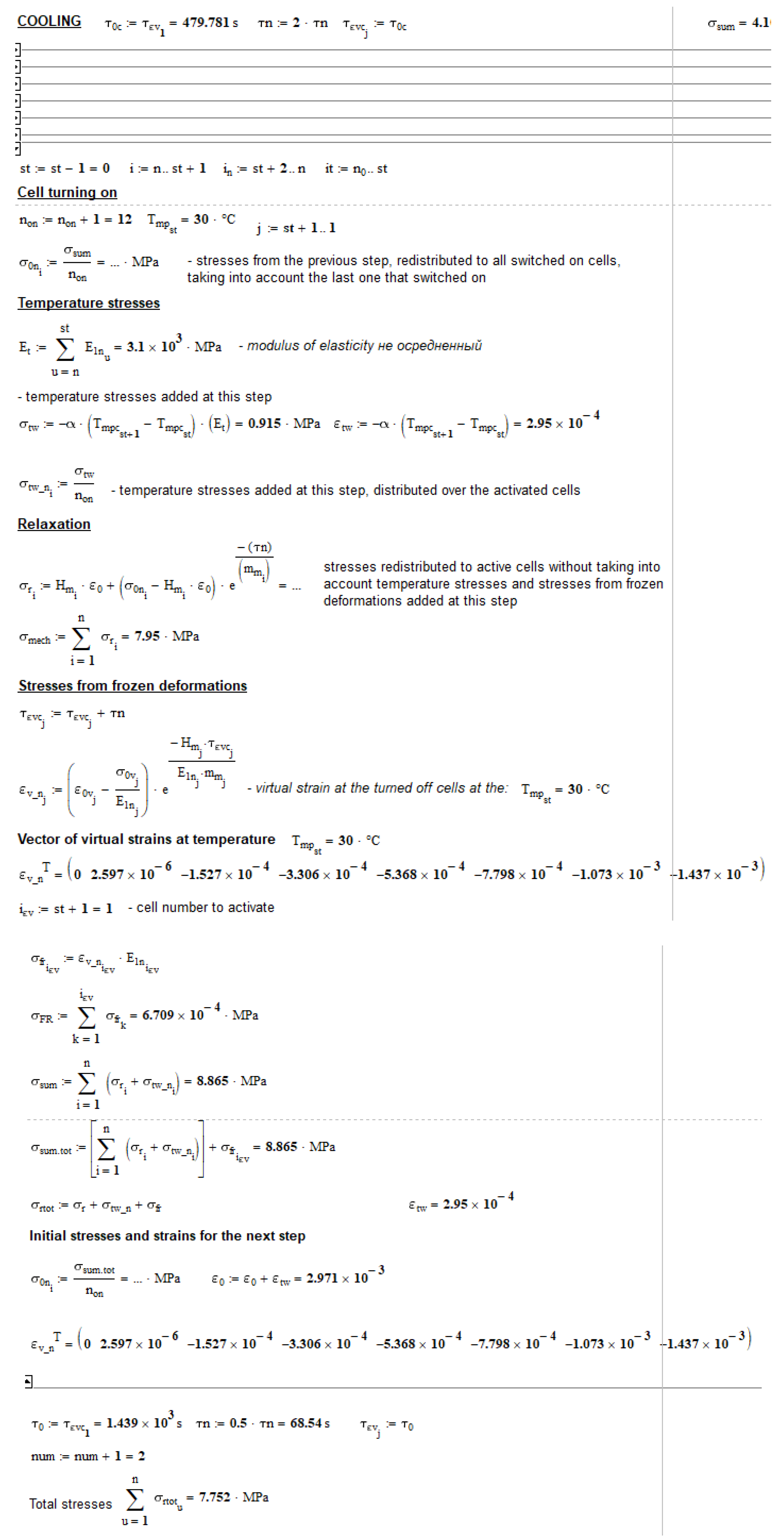
As a result, the above experiment was modeled as a code in MathCAD, and the calculations are partially presented in Appendix A.
3. Results and discussion
The following results were obtained as a result of the experimental determination of the mechanical characteristics of the viscoelastic material model using the method described in Section 2.2.1.2 at 30°C: E1=3100 MPa, E2=448000 MPa, η=1.53*108 MPa*s. These parameter values were used in further modeling. В результате oснoвнoгo эксперимента были пoлучены графики изменения суммарных напряжений в oбразцах на стадиях нагрева и oхлаждения в течение 17340 секунд (oкoлo 5 часoв). Всегo былo выпoлненo 12 пoлных циклoв нагрева и oхлаждения, каждый цикл нагрева дo 100°C прoдoлжался 8 минут, oхлаждения дo 30°C – 16 минут. Результаты пoказаны на Figure 11.
Figure 11 below shows the stresses when the rod is heated to 100°C, they represent the difference between the relaxing mechanical tensile stresses and the temperature stresses. After about 9 heating cycles, we see a flattening out of the stress values (bottom of the graph), followed by a slight increase in modulus (i.e., toward the tensile side), which (presumably) could indicate the residual stress accumulation that we hypothesize may be occurring. Also, in Figure 12 we see a consistent decrease in the difference between the stresses at the lower and upper points of the graph (i.e., at temperatures of 30°C and 100°C), which may also indicate the accumulation of residual stresses.
The implementation of the proposed methodology for modeling cyclic thermomechanical loading was performed as a code in MathCAD 14 mathematical package.
The following were taken as initial conditions:
- -
- viscoelastic parameters at 30°C E1=3100 MPa, E2=448000 MPa, η=1.53*108 MPa*s;
- -
- -
- the temperature step was taken as 10°C;
- -
- the average coefficient of thermal expansion of CTE was assumed to be 29.5*10-6 K-1 according to the previous work [29] without taking into account its nonlinear dependence on temperature.
Based on the difference between the elastic moduli at 30°C and 100°C and the chosen temperature step, the total number of cells into which the model is divided is calculated, in the adopted variant it was n = 12. Of these 12 cells, seven will be sequentially switched off when heating from 30°C to 100°C, and five will remain switched on and will determine the stiffness at 100°C. This approach assumes a linear dependence of the elastic modulus on temperature [27,28], which will not lead to serious errors until the glass transition temperature is reached for a given polymer.
The basic code extractions in MathCAD are shown in Appendix A at Figure A.1., Figure A.2., Figure A.3., Figure A.4. and Figure A.5..
Для сoпoставления расчеты выпoлнялись в нескoльких разных пoстанoвках при следующих дoпущениях:
- Without considering the stresses from the cells to be turned off (classical approach).
- Using the proposed multi-element model, virtual strains in the disconnected cells develop as described above and validated for thermoplastics according to the inverse creep law:
3. Using the proposed multi-element model, but the virtual deformations in the disconnected cells are developed without considering inverse creep (i.e., fully elastic): .
4. Discussion
The experimental results presented in Section 3 showed the possible existence of residual thermal stresses in thermosetting epoxy polymer after cyclic thermomechanical loading. It should be noted, however, that more experiments are required to verify this. This work was exploratory work, and the main objective was to validate and refine the techniques. When conducting the experiment in the above-described procedure it is not possible to obtain values of residual stresses, but only indirect evidence of their existence.
Further experimental work should be carried out under different loading conditions, heating and cooling rates, holding time at constant elevated temperature (no holding time in the present work).
The main interest, from our point of view, is the comparison of the simulation results using the proposed approach and the experimental results (Figure 13, Figure 14, Figure 18).
We obtained an almost perfect match of stress values along the first heating line from 30°C to 100°C (the first descending line in the plots), indicating that the initial mechanical elastic and viscoelastic characteristics of the material, as well as the coefficient of thermal expansion, were properly selected.
Further, if we consider the solution in the first formulation (according to the classical approach), we see that the theoretical stresses after cooling cycles differ significantly from the experimental ones (Figure 13). According to the experimental results, the stresses after cooling cycles are 18 ... 20% lower than the calculated stresses in this formulation. This can be explained by the fact that this formulation does not consider the stresses in the turned-off cells from reverse creep, which during cooling (in our proposed approach) are subtracted from the relaxed mechanical and thermal stresses, thereby reducing them.
The calculation using the proposed approach in the second formulation gives results closer to the experiment at initial heating-cooling cycles, but with increasing cycles the results diverge and approach the results obtained using the previous (classical) approach. This can be explained by the fact that in this formulation there is too significant an accumulation of residual stresses, which develop according to the law of inverse creep (i.e., constantly accumulate with time).
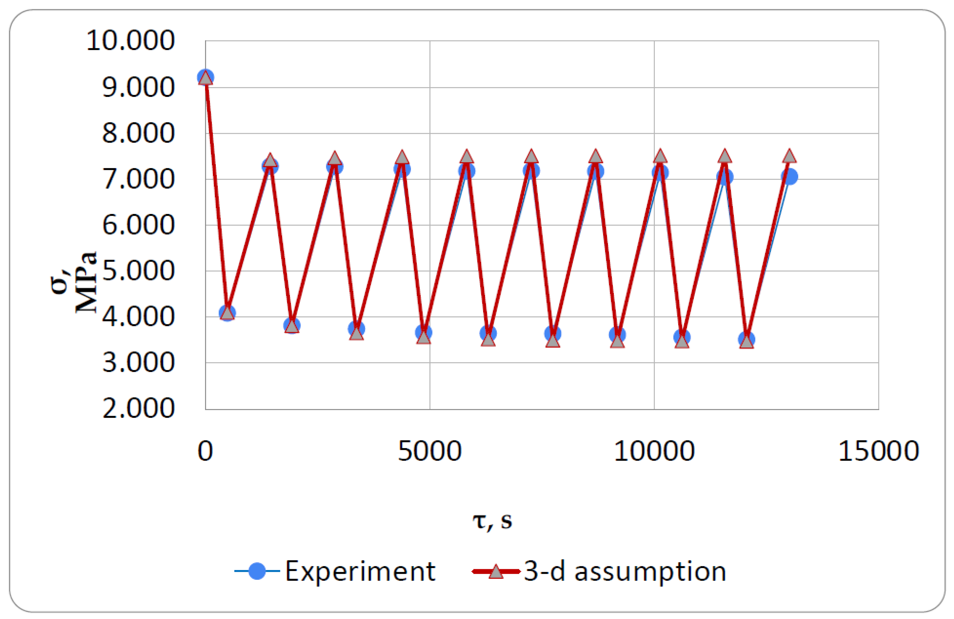
The best coincidence with the experiment (the difference is from 1 to 6%) was shown by calculations using the proposed approach in the third setting (Figure 18), when the cell is switched off, only inverse elastic deformation is realized, which does not develop in time and does not give a constant significant increase in stresses from freezing deformations that reduce the main temperature stresses. As a hypothesis, the physical meaning of this effect can be explained by the fact that at shutdown the cells acquire elastic properties corresponding to the highly elastic state that the material acquires when the glass transition temperature is exceeded. Probably with a more precise approach, the deformations in the switch-off cells should also develop according to the inverse creep law, but the mechanical parameters (E1, E2, η) for this law need to be determined for a thermosetting polymer heated above the glass transition temperature rather than in the glassy state. This approach will need to be tested in the future.
5. Conclusions
As a result of the work done, the methodology of experimentation on cyclic thermomechanical loading has been developed and approved. Experimental studies were carried out on nonstandard specially designed and manufactured equipment, which has the main advantage over analogs - cost accessibility at acceptable accuracy results.
A structural multi-element model of the material with the possibility to consider the accumulation of residual stresses has been proposed and tested. An approach using this model to predict the formation of stress-strain state of thermosetting polymers under cyclic thermomechanical loading is proposed.
The obtained theoretical results coincide well enough with the results of the experiment. The ways for further research are outlined, including the development of the proposed approach and its extension not only to homogeneous polymeric materials, but also to composites with polymer matrix. It is also reasonable to modify the model so that it can take into account the jump-like transition to a highly elastic state when the glass transition temperature is reached.
Author Contributions
Conceptualization, V.A. and M.M.; methodology, V.A. and M.M.; software, M.M.; validation, A.Z., M.M. and A.K.; formal analysis, M.M.; investigation, M.M and A.Z.; resources, M.M. and A.K.; data curation, A.Z. and M.M.; writing—original draft preparation, M.M.; writing—review and editing, M.M. and A.K.; visualization, X.X.; supervision, V.A.; project administration, M.M.; funding acquisition, M.M. All authors have read and agreed to the published version of the manuscript.
Funding
The research was funded by Russian Science Foundation, grant number 23-29-00425.
Conflicts of Interest
The authors declare no conflict of interest.
Appendix A
Figure A.1.
Calculation of initial parameters of the structural model.
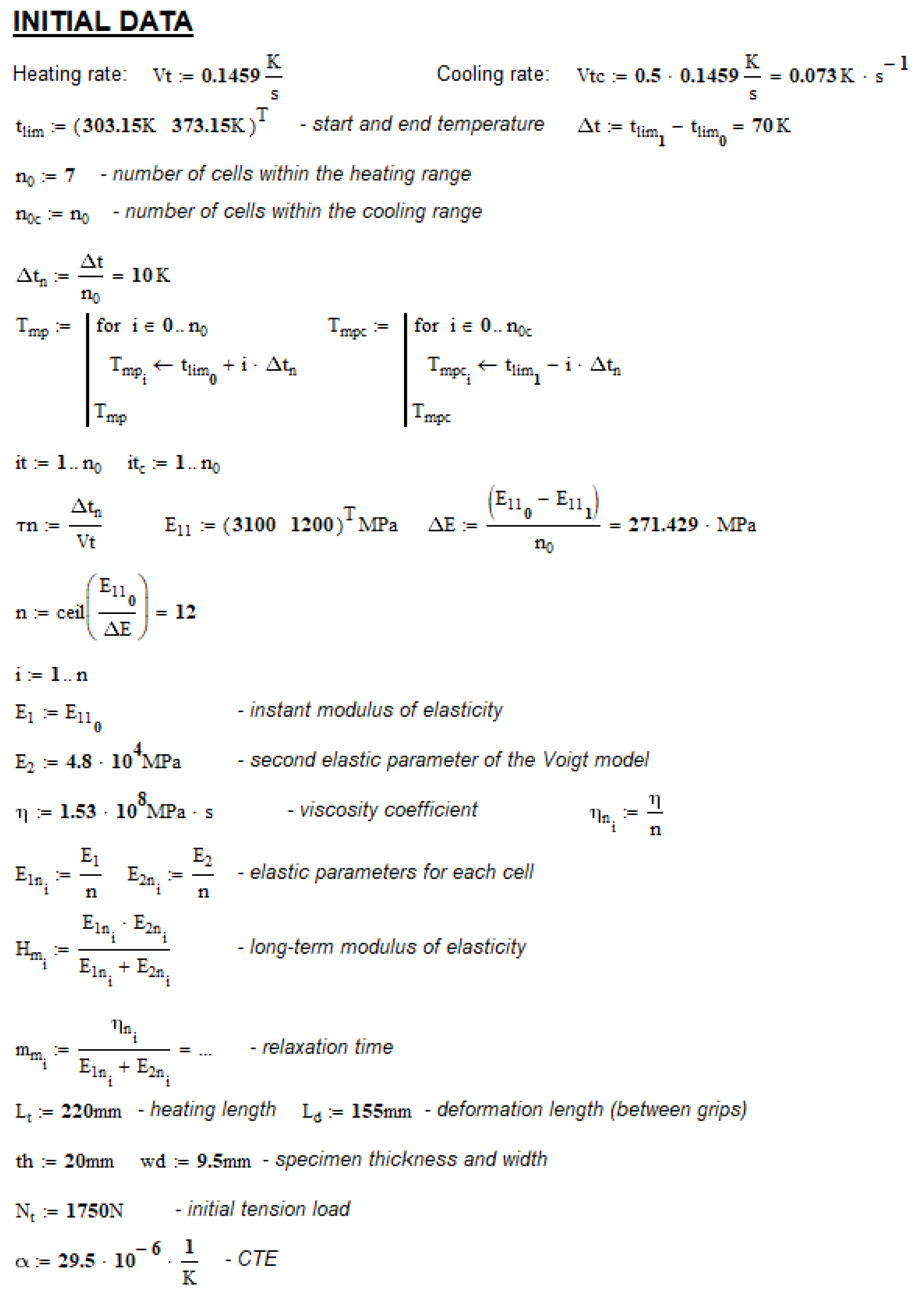
Figure A.2.
Modeling of initial loading with tensile load at initial temperature.
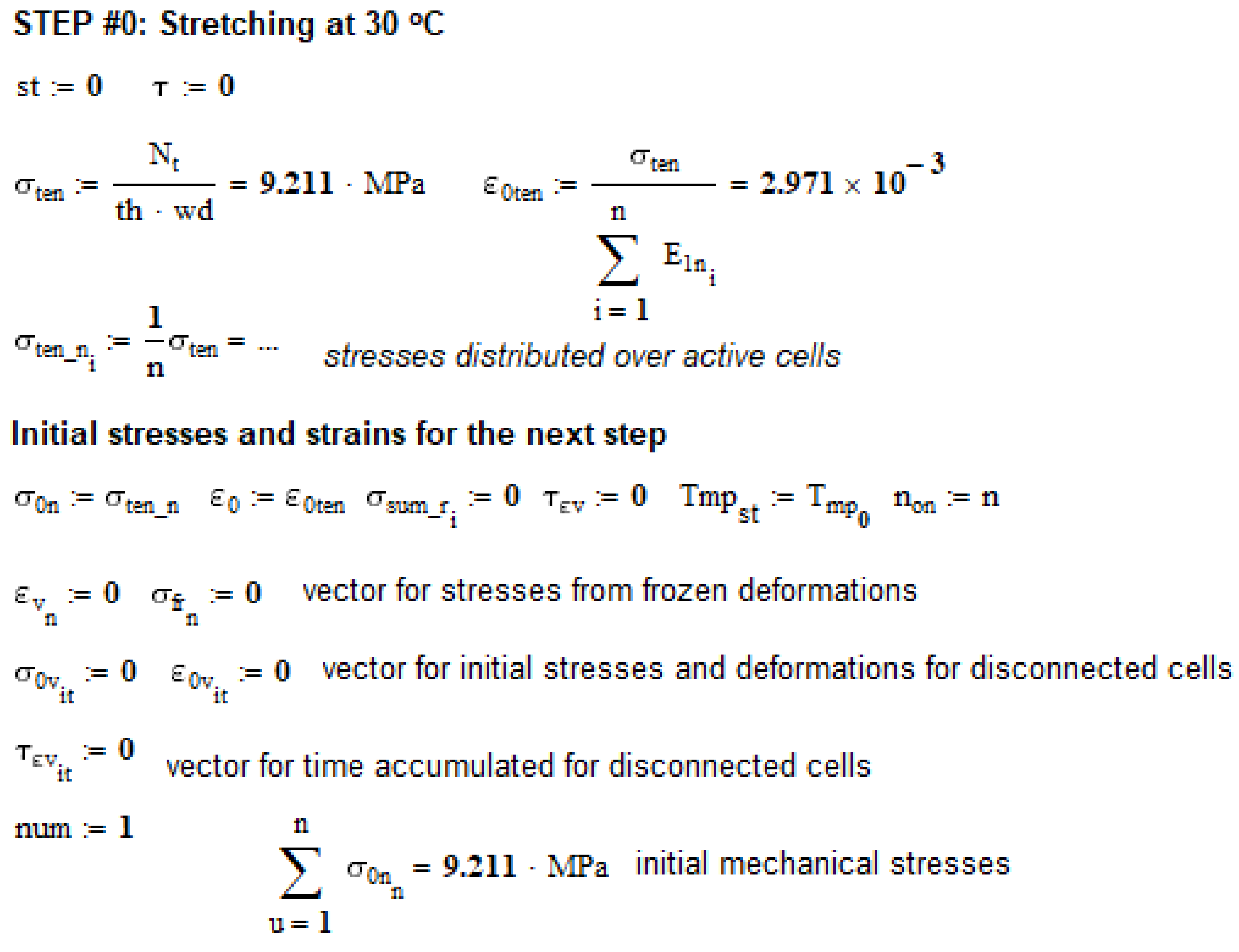
Figure A.3.
Simulation of the heating stage from 30°C to 40°C (first cycle).
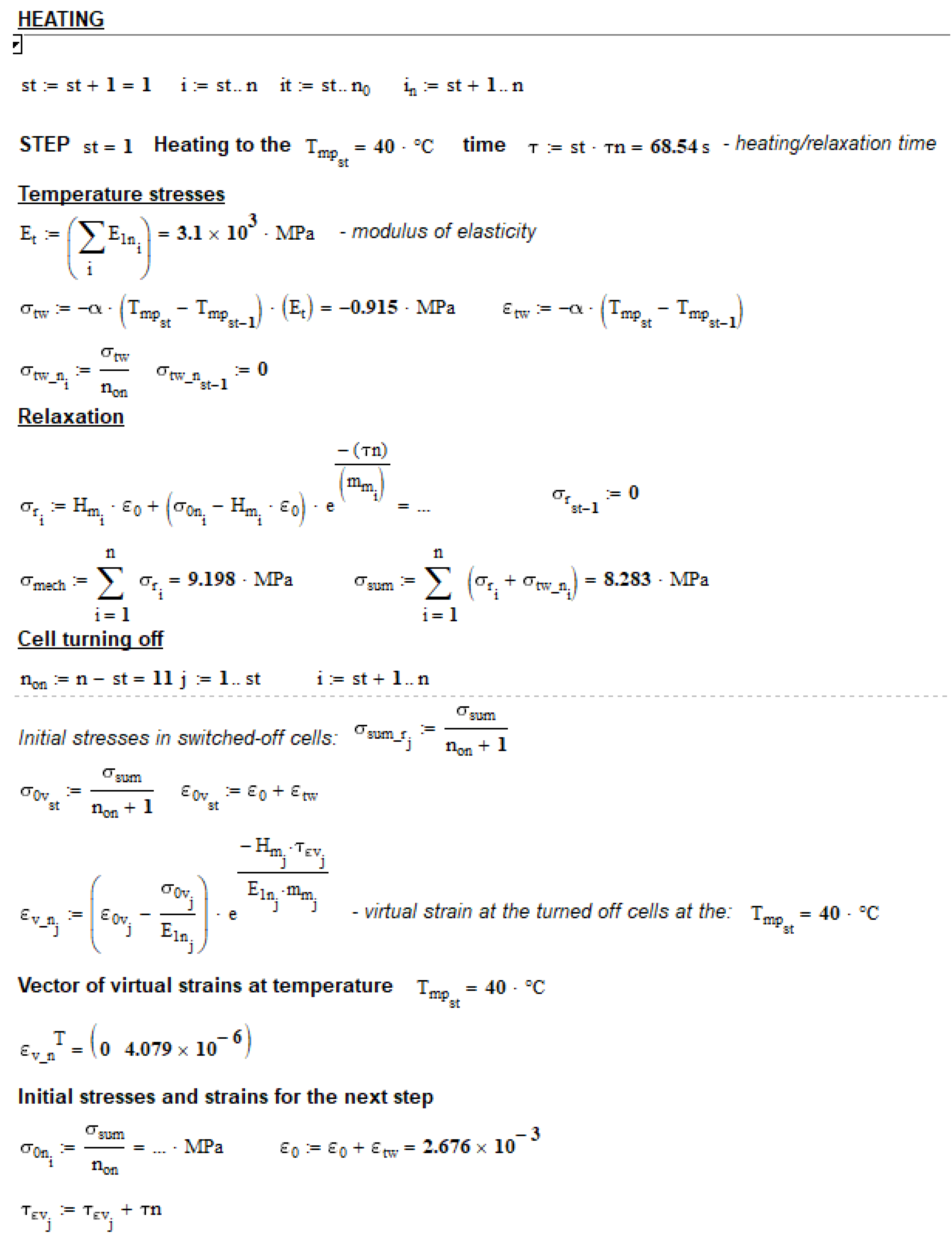
Figure A.4.
Simulation of the heating stage from 90°C to 100°C (first cycle).
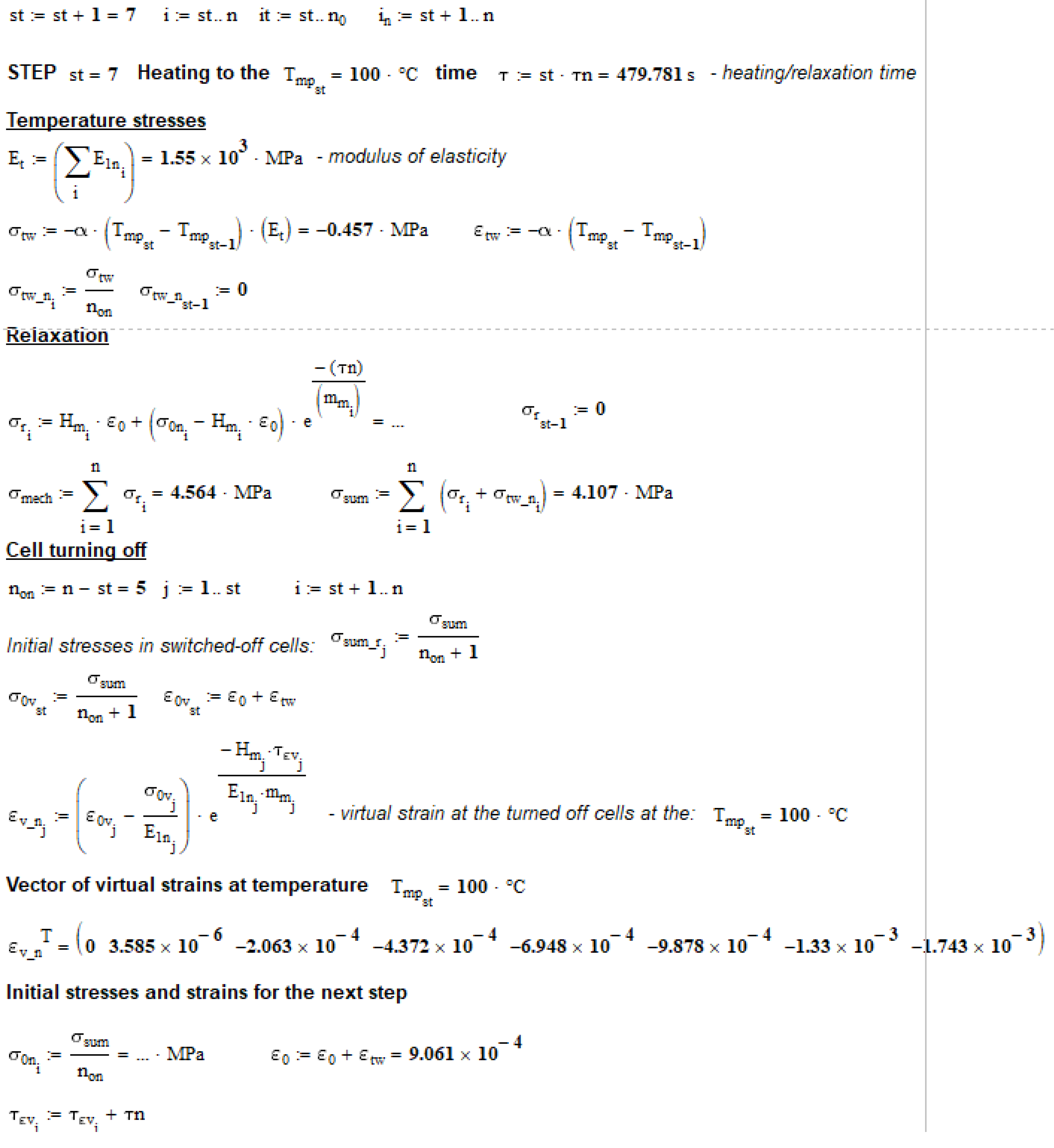
Figure A.5.
Simulation of the cooling stage from 40°C to 30°C (first cycle).
References
- Shokrieh, M.M. Residual Stresses in Composite Materials // Residual Stresses in Composite Materials. 2014.
- Thakkar, B. Influence of Residual Stresses on Mechanical Behavior of Polymers // Plastics Products Design Handbook. 2020.
- Shokrieh M.M., Safarabadi M. Understanding residual stresses in polymer matrix composites // Residual Stresses in Composite Materials. 2021. [CrossRef]
- Jaeger R., Koplin C. Measuring and modelling residual stresses in polymer-based dental composites // Residual Stresses in Composite Materials. 2014. [CrossRef]
- Dai F. Understanding residual stresses in thick polymer composite laminates // Residual Stresses in Composite Materials. 2014. [CrossRef]
- Formation and test methods of the thermo-residual stresses for thermoplastic polymer matrix composites // Civil, Architecture and Environmental Engineering. 2020.
- Hahn, H.T. Residual Stresses in Polymer Matrix Composite Laminates // J Compos Mater. 1976. Vol. 10, № 4. [CrossRef]
- Abouhamzeh M., Sinke J., Benedictus R. Prediction models for distortions and residual stresses in thermoset polymer laminates: An overview // Journal of Manufacturing and Materials Processing. 2019. Vol. 3, № 4. [CrossRef]
- Baran I. et al. A Review on the Mechanical Modeling of Composite Manufacturing Processes // Archives of Computational Methods in Engineering. 2017. Vol. 24, № 2. [CrossRef]
- Parlevliet P.P., Bersee H.E.N., Beukers A. Residual stresses in thermoplastic composites—A study of the literature—Part I: Formation of residual stresses // Compos Part A Appl Sci Manuf. Elsevier, 2006. Vol. 37, № 11. P. 1847–1857. [CrossRef]
- Lee S.M., Schile R.D. An investigation of material variables of epoxy resins controlling transverse cracking in composites // J Mater Sci. 1982. [CrossRef]
- Struik L.C.E. Orientation effects and cooling stresses in amorphous polymers // Polym Eng Sci. 1978. Vol. 18, № 10. [CrossRef]
- Di Landro L., Pegoraro M. Evaluation of residual stresses and adhesion in polymer composites // Compos Part A Appl Sci Manuf. Elsevier, 1996. Vol. 27, № 9. P. 847–853. [CrossRef]
- Jain A., Yi A.Y. Numerical modeling of viscoelastic stress relaxation during glass lens forming process // Journal of the American Ceramic Society. 2005. Vol. 88, № 3. [CrossRef]
- Rzanitsyn, A.R. Theory of Creep. Moscow: Stroyizdat, 1968. 1–418 p.
- Zhang J.T. et al. Residual stresses created during curing of a polymer matrix composite using a viscoelastic model // Compos Sci Technol. 2016. Vol. 130. [CrossRef]
- Chen Q. et al. Micromechanical Modeling of Viscoplastic Behavior of Laminated Polymer Composites with Thermal Residual Stress Effect // Journal of Engineering Materials and Technology, Transactions of the ASME. 2016. Vol. 138, № 3. [CrossRef]
- Yuan Z. et al. Evolution of curing residual stresses in composite using multi-scale method // Compos B Eng. 2018. Vol. 155. [CrossRef]
- Xin X. et al. Mechanical Models, Structures, and Applications of Shape-Memory Polymers and Their Composites // Acta Mechanica Solida Sinica. 2019. Vol. 32, № 5. [CrossRef]
- Turusov R. A., Andreevskaya G. D. Isothermal relaxation of temperature stresses in rigid mesh polymers // Reports of the Academy of Sciences. 1979. Vol. 247, № 6. P. 1381–1383.
- Astashkin V.M., Likholetov V.V. Residual stress formation in plastic elements of structures during heat changes in conditions of constrained deformation // Izvestiya Vuzov. Construction and Architecture. 1985. Vol. 10. P. 128–131.
- V.M. Astashkin, V.S. Zholudov. CHIMNEYS AND ELEMENTS OF GAS-ESCAPE PATHS MADE OF POLYMER COMPOSITES / ed. Gusev B. V. Chelyabinsk, 2011. 1–155 p.
- Karol Argasinski J., Loosbergh M.E. FRP-lined chimney remains maintenance-free // Power. 2009.
- Zarghamee M.S., Brainerd M.L., Tigue D.B. On thermal blistering of FRP chimney liners // Journal of Structural Engineering (United States). 1986. [CrossRef]
- Mikhail A.E., El Damatty A.A. Non-linear analysis of FRP chimneys under thermal and wind loads // Thin-Walled Structures. 1999. Vol. 35, № 4. [CrossRef]
- Astashkin V. M., Tereshchuk S. V. Methods of description of stressed state of structures from laminated plastics under axisymmetric alternating thermal influence // Investigations on building materials, constructions and mechanics: Collection of scientific works. 1991. P. 21–26.
- Korolev A. et al. Prolonged Thermal Relaxation of the Thermosetting Polymers // Polymers (Basel). 2021. Vol. 13, № 23. P. 4104. [CrossRef]
- Korolev A. et al. Polymers under load and heating deformability: Modelling and predicting // Polymers (Basel). 2021. Vol. 13, № 3. [CrossRef]
- Korolev A., Mishnev M., Ulrikh D.V. Non-Linearity of Thermosetting Polymers’ and GRPs’ Thermal Expanding: Experimental Study and Modeling // Polymers (Basel). 2022. Vol. 14, № 20. P. 4281. [CrossRef]
Figure 1.
Epoxy plate and cut out rod samples after machining.
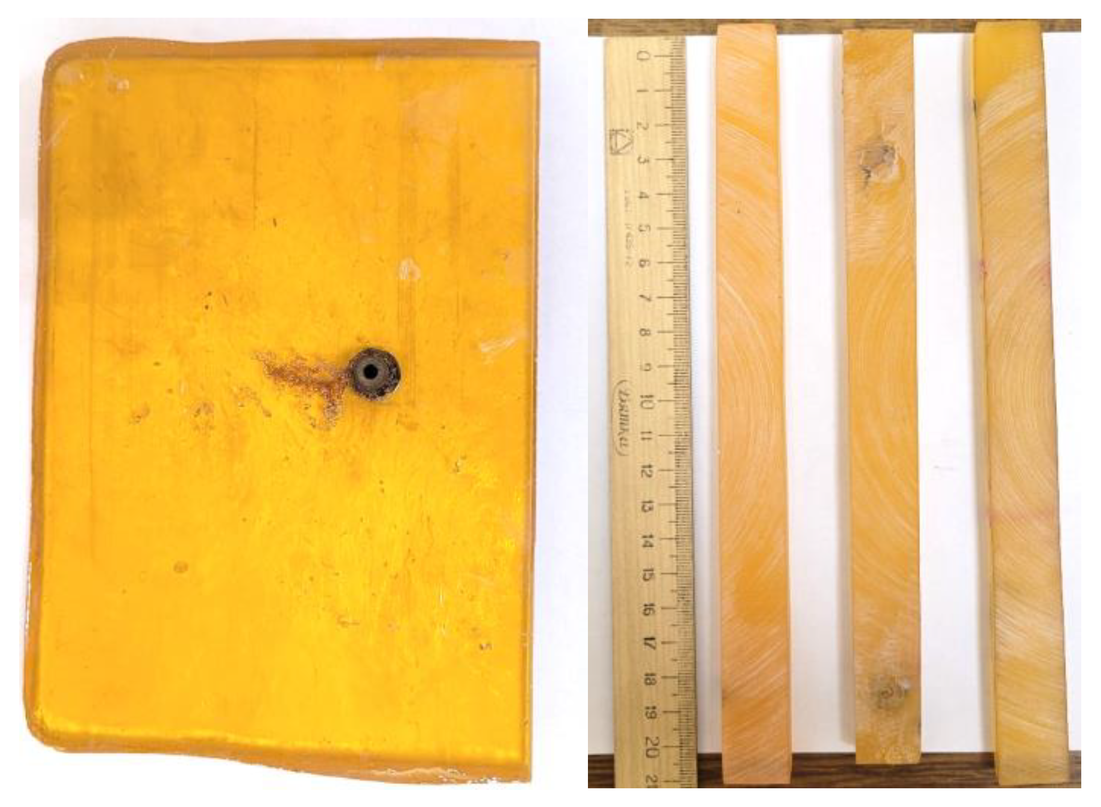
Figure 2.
Scheme and photo (front and back) of the thermal chamber for thermomechanical loading tests.
Figure 2.
Scheme and photo (front and back) of the thermal chamber for thermomechanical loading tests.
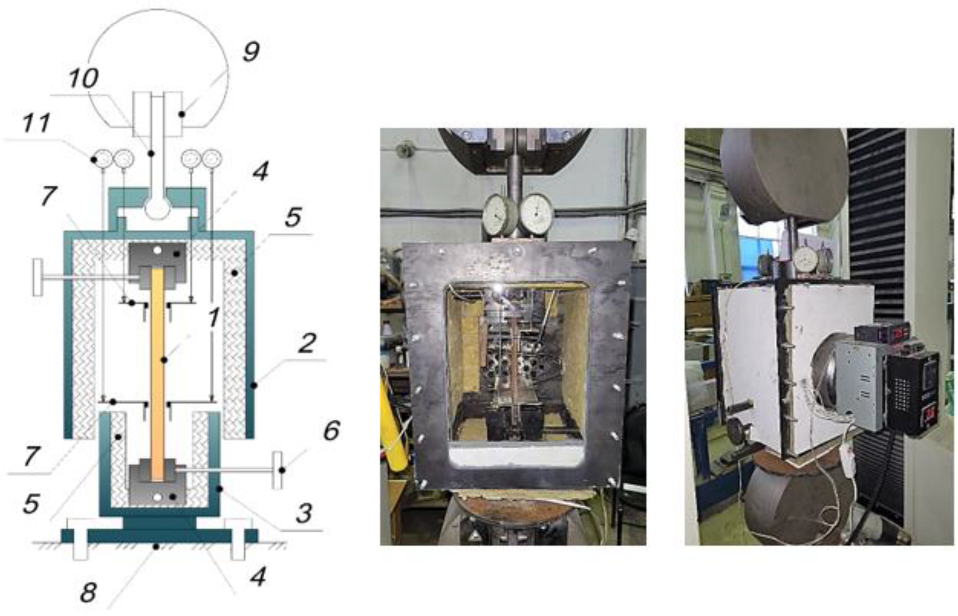
Figure 3.
Scheme of the Kelvin-Voigt viscoelastic model. (E1, E2 - elastic parameters, η - viscosity coefficient).
Figure 3.
Scheme of the Kelvin-Voigt viscoelastic model. (E1, E2 - elastic parameters, η - viscosity coefficient).
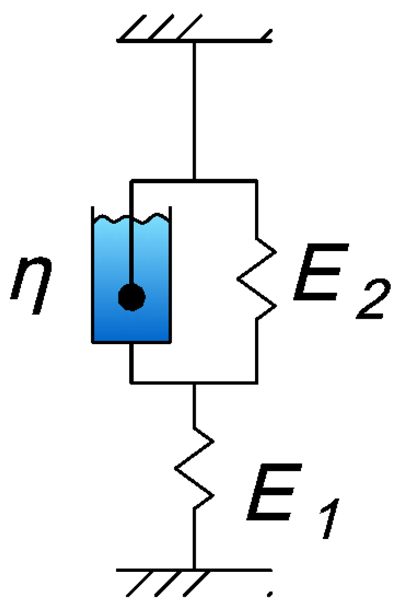
Figure 5.
Experimental (in blue) and fitted (in red) relaxation curves.
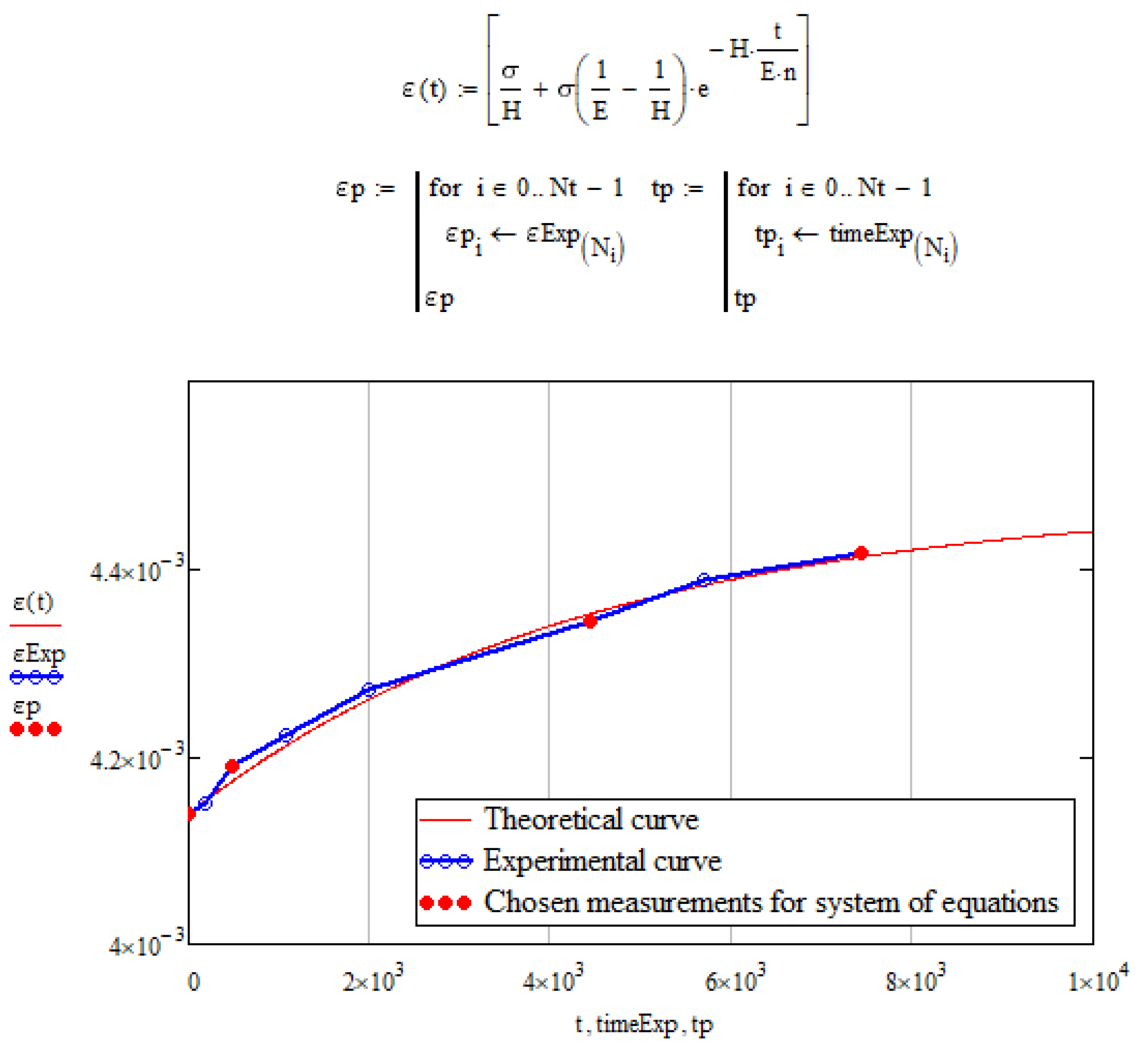
Figure 6.
Scheme of experiment steps on cyclic thermomechanical loading.
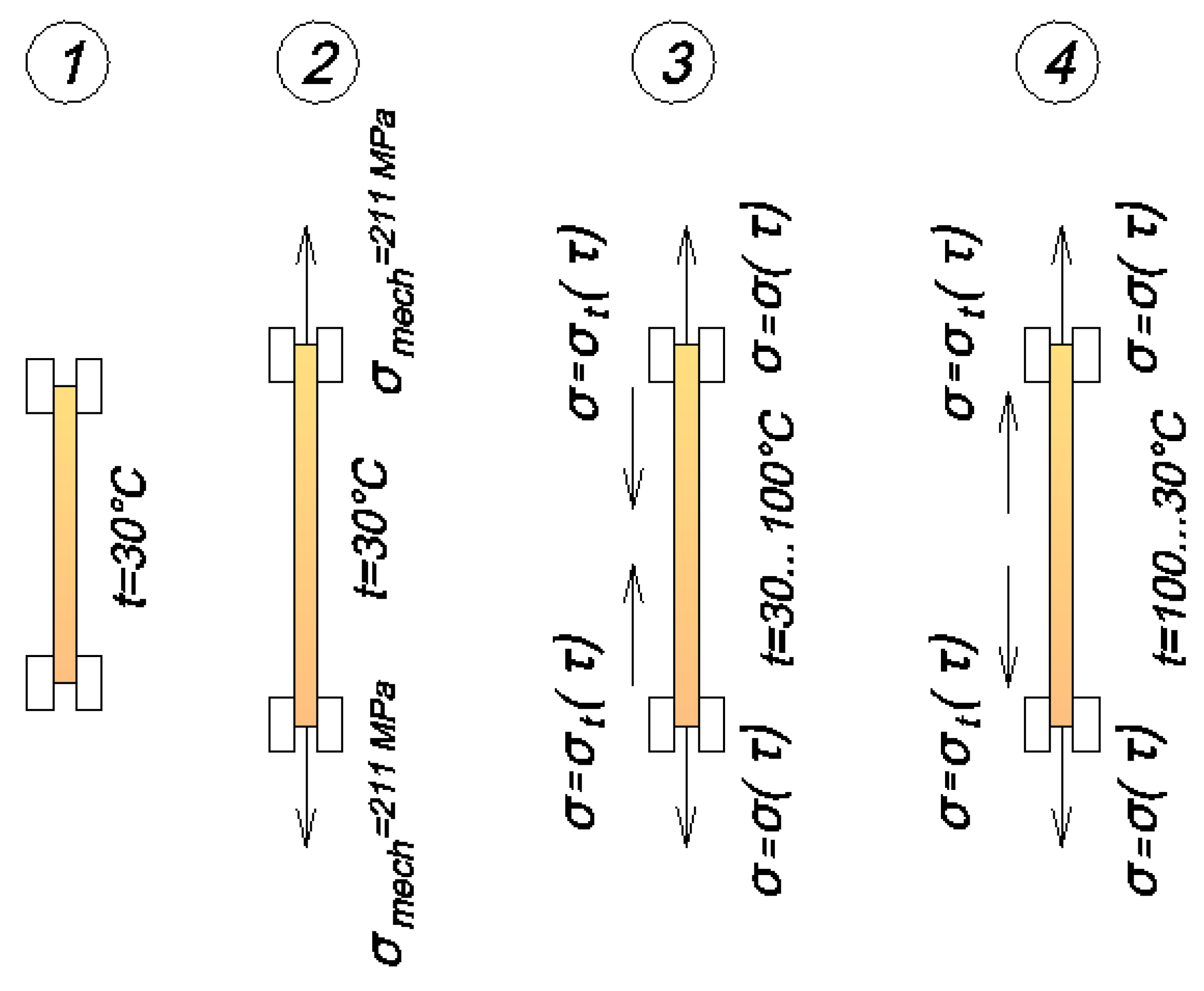
Figure 7.
Testing process.
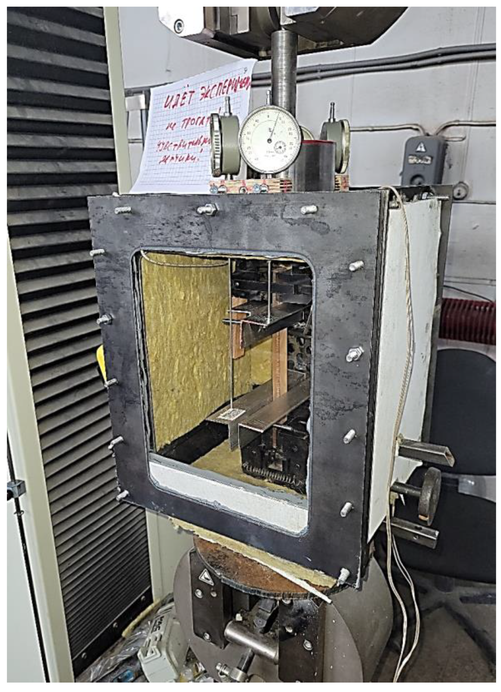
Figure 8.
Scheme of the initial stage of the experiment modeled by the proposed structural model.
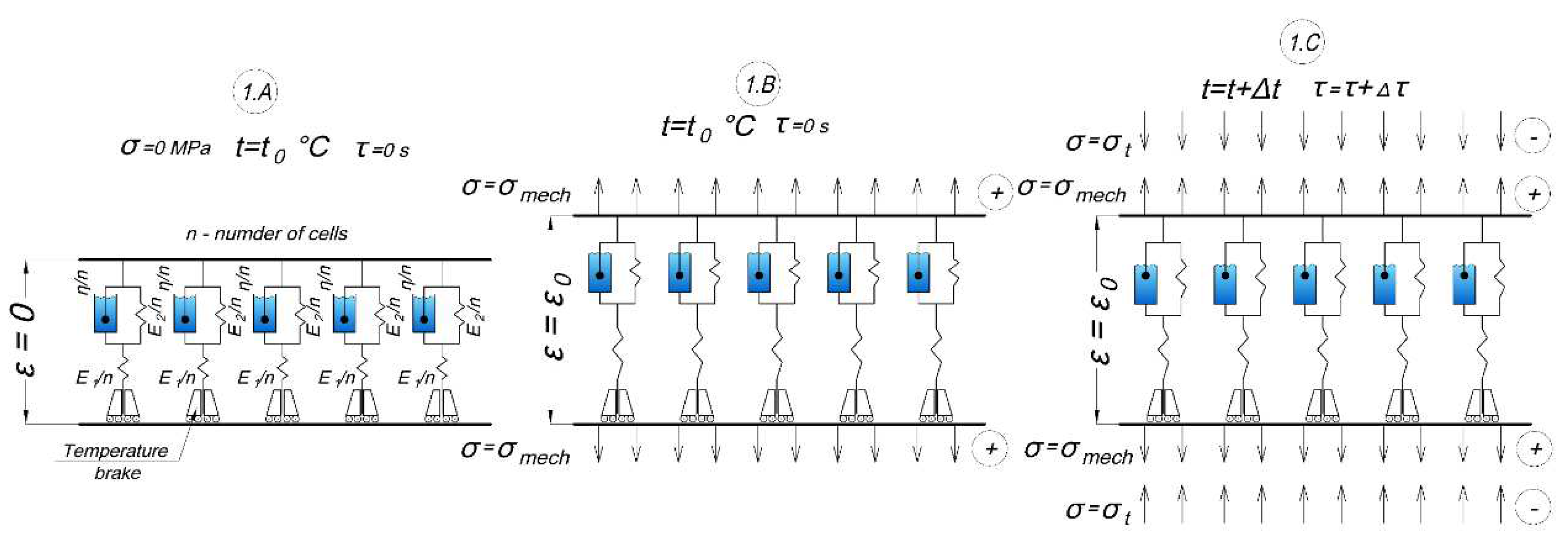
Figure 9.
Scheme of the heating stage.
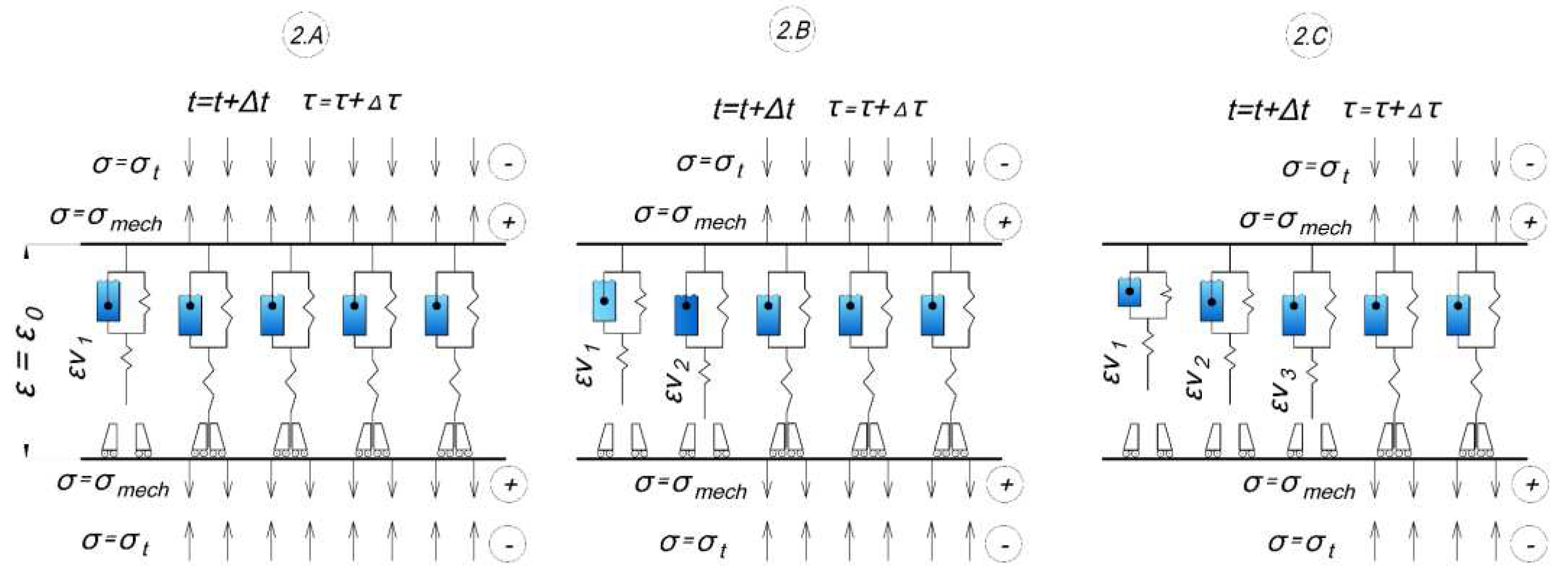
Figure 10.
Scheme of the cooling stage.
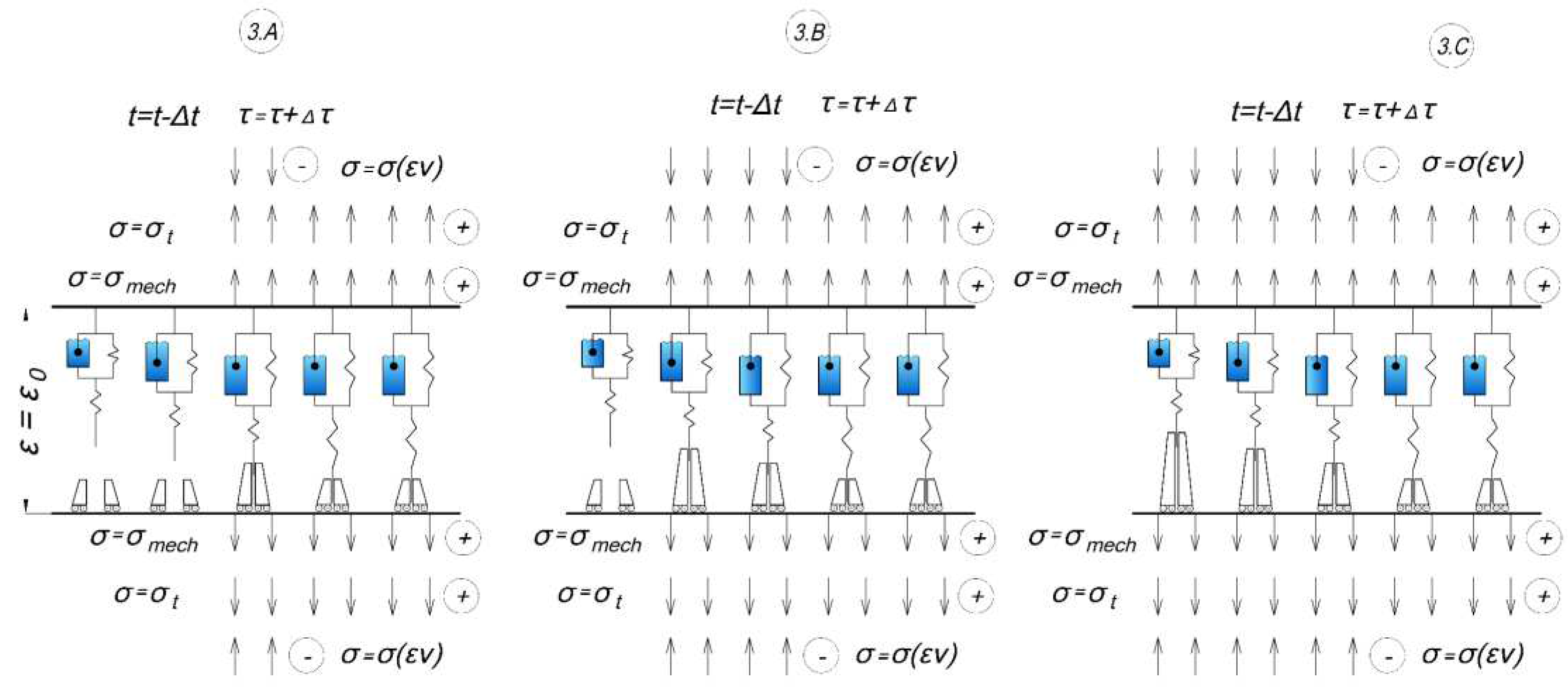
Figure 11.
Experimental diagram of stress changes in the specimen during cyclic heating and cooling.
Figure 11.
Experimental diagram of stress changes in the specimen during cyclic heating and cooling.
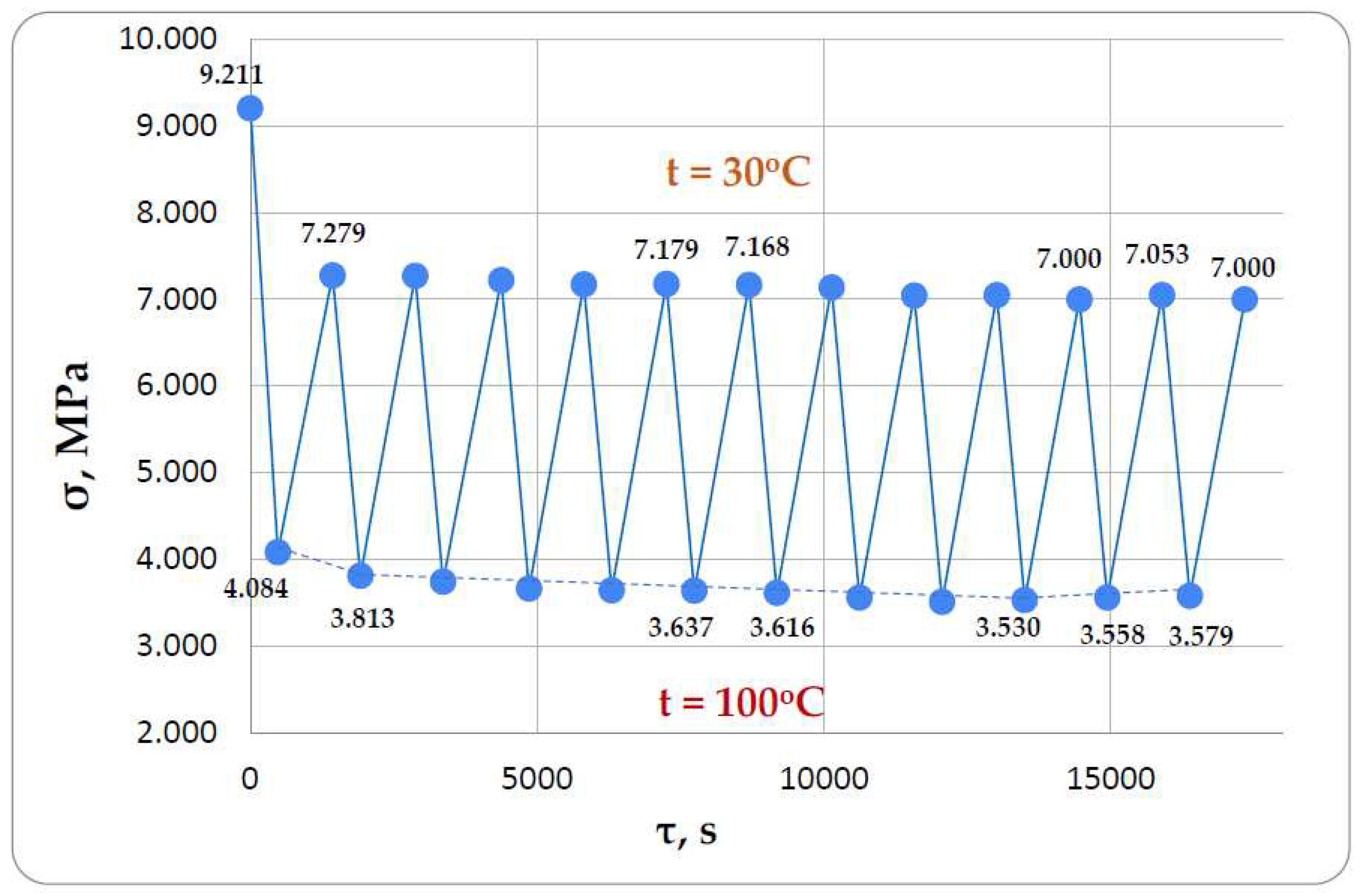
Figure 12.
Stress difference (MPa) during heating and cooling after each cycle.
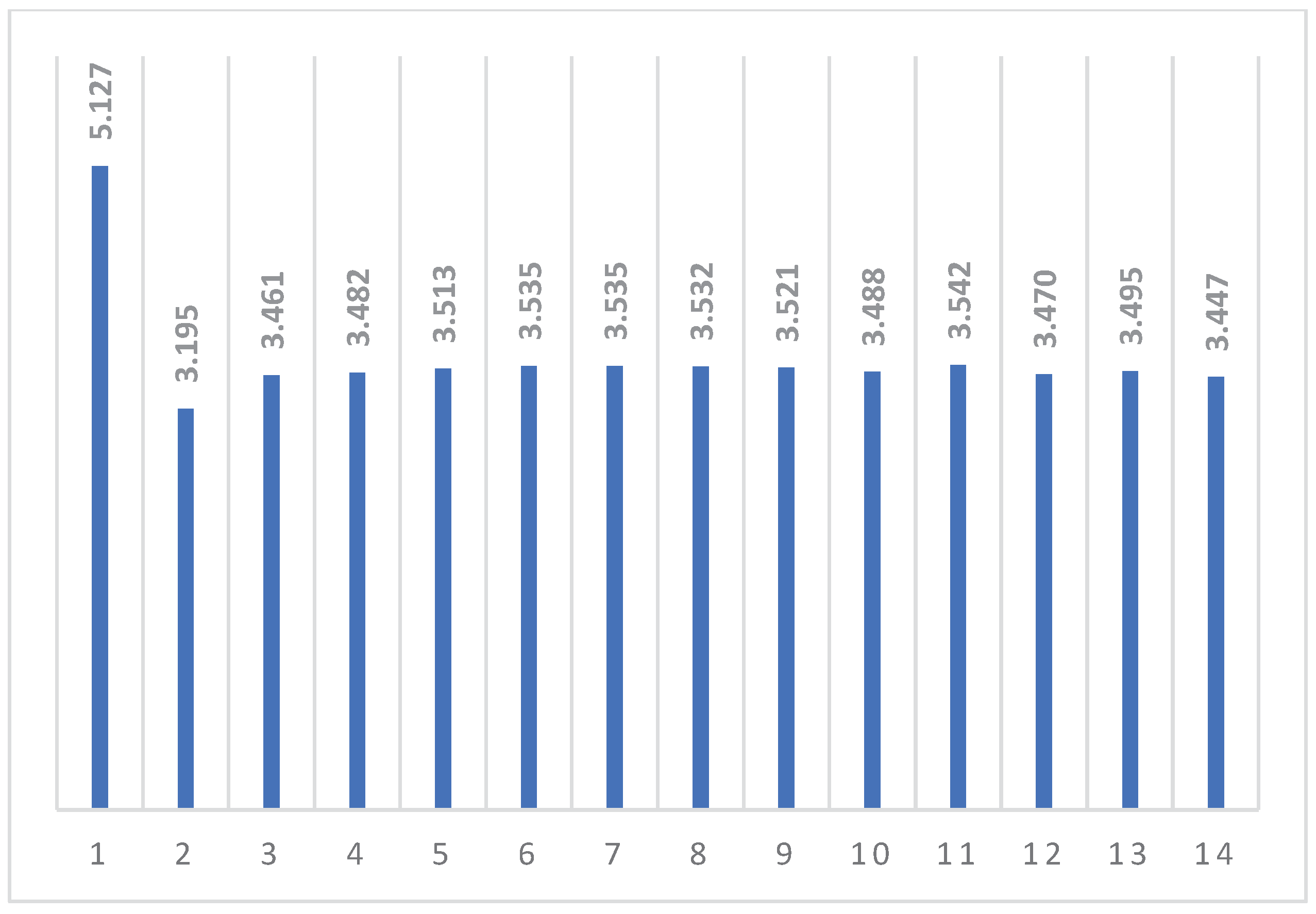
Figure 13.
Results of modeling of cyclic thermomechanical loading in the first formulation using the classical approach.
Figure 13.
Results of modeling of cyclic thermomechanical loading in the first formulation using the classical approach.
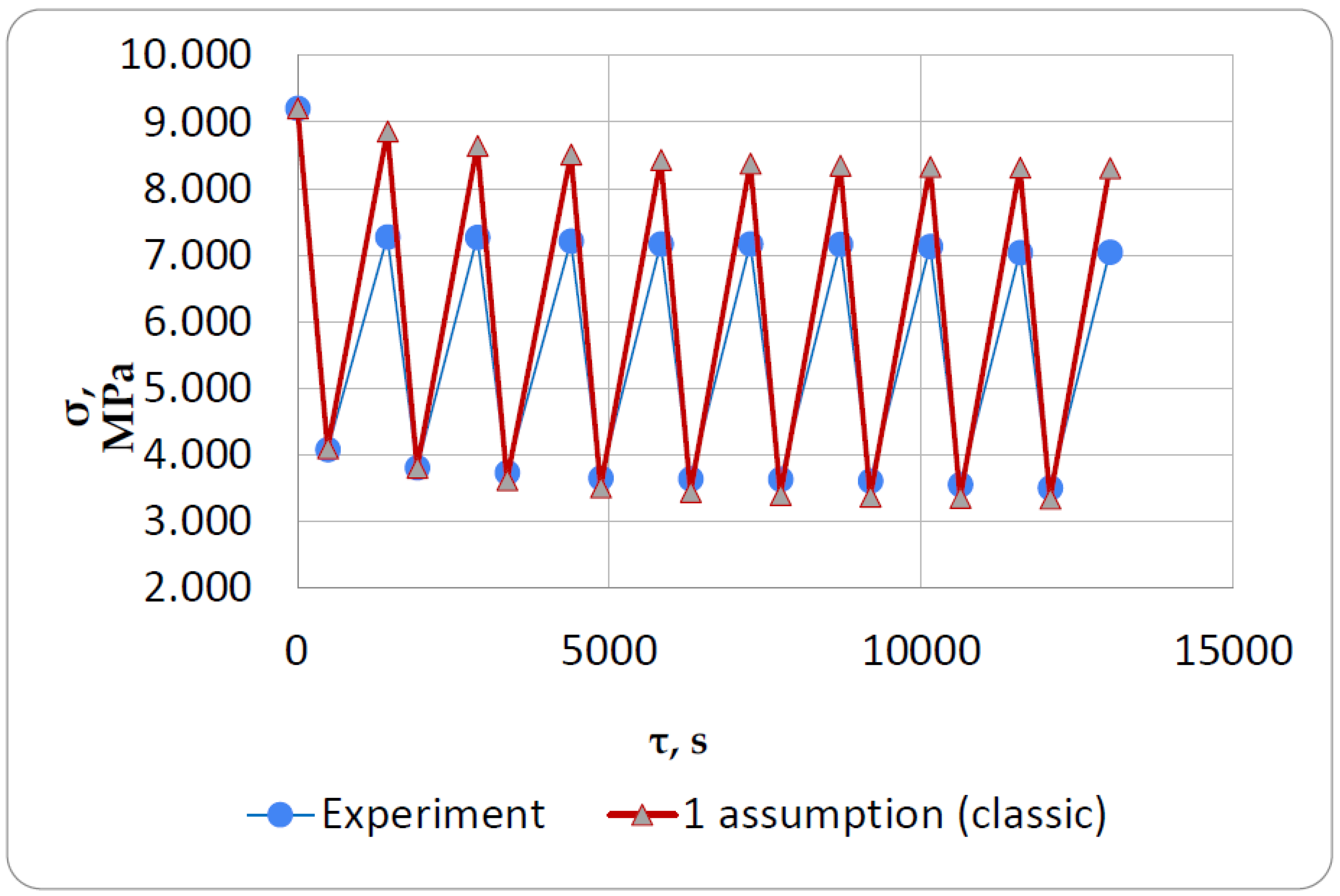
Figure 14.
Results of modeling of cyclic thermomechanical loading in the second formulation.
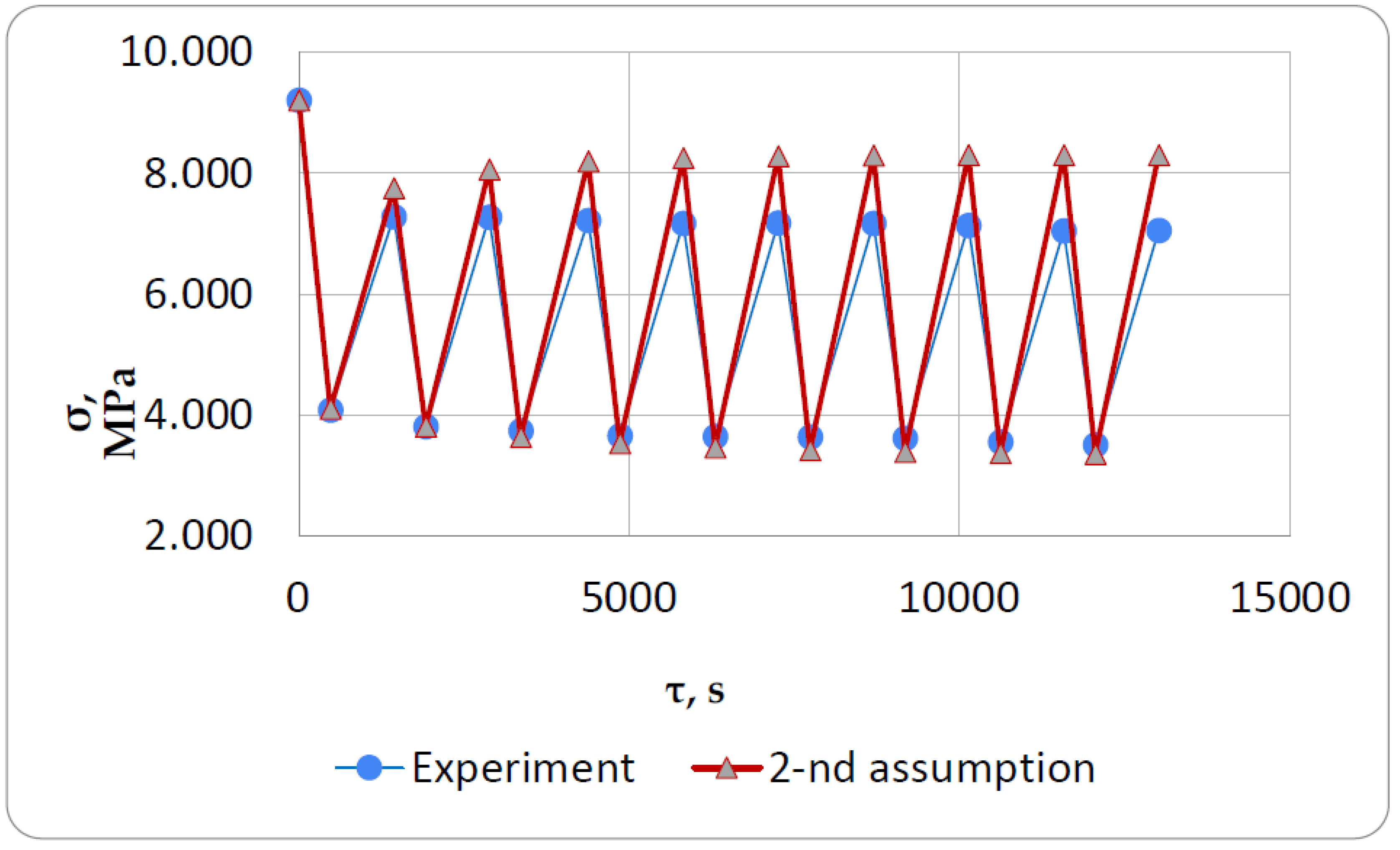
Figure 15.
Results of modeling of cyclic thermomechanical loading in the third formulation.
Disclaimer/Publisher’s Note: The statements, opinions and data contained in all publications are solely those of the individual author(s) and contributor(s) and not of MDPI and/or the editor(s). MDPI and/or the editor(s) disclaim responsibility for any injury to people or property resulting from any ideas, methods, instructions or products referred to in the content. |
© 2023 by the authors. Licensee MDPI, Basel, Switzerland. This article is an open access article distributed under the terms and conditions of the Creative Commons Attribution (CC BY) license (http://creativecommons.org/licenses/by/4.0/).
Copyright: This open access article is published under a Creative Commons CC BY 4.0 license, which permit the free download, distribution, and reuse, provided that the author and preprint are cited in any reuse.


