
Submitted:
04 November 2024
Posted:
05 November 2024
You are already at the latest version
Abstract
Trunk-like robots have attracted a lot of attention in the community of researchers interested in the general field of bio-inspired soft robotics, because trunk-like soft arms may exhibit high dexterity and adaptability very similar to the elephants and potentially quite superior to traditional articulated manipulators. In view of practical applications, the integration of a soft hydrostatic segment with a hard-articulated segment, i.e. a hybrid kinematic structure similar to the elephant’s body, is probably the best design framework. It is proposed that this integration should occur at the conceptual/cognitive level before being implemented in specific soft technologies, including the related control paradigms. The proposed modeling approach is based on the Passive Motion Paradigm (PMP), originally conceived for addressing the degrees of freedom problem of highly-redundant, articulated structures. It is shown that this approach can be naturally extended from highly-redundant to hyper-redundant structures, including hybrid structures that include a hard and a soft component. The PMP model is force-based, not motion-based and is characterized by two main computational modules: the Jacobian matrix of the hybrid kinematic chain and a Compliance matrix that maps generalized force fields into coordinated gestures of the whole body-model. It is shown how the modulation of the compliance matrix can be used for the synergy formation process, that coordinates the hyper-redundant nature of the hybrid body-model and, at the same time, for the preparation of the trunk-tip in view of a stable physical interaction of the body with the environment, in agreement with the general impedance-control concept.
Keywords:
Biomimetic robotics
; Cognitive robotics
; Soft robotics
; Hydrostat
; Neural simulation of action
; Prospection
; Passive Motion Paradigm
; Generative Body Schema
; Degrees of freedom problem
1. Introduction
Two main “technological families” emerged during evolution for providing animal species with a high degree of motoric and manipulatory skills: muscle-activated skeletal systems and muscular hydrostats. In the case of the elephant, the two technologies appear to be functionally integrated as a unitary cyber-physical system that enhances the specific flexibility aspects of each motoric technology. However, if we compare the approximately 40,000 muscles of the elephant’s trunk, arranged in a combination of longitudinal, radial, transversal, and oblique muscle groups, with the relative paucity of the human body (650-840 skeletal muscles with 300-400 mono/bi/tri-articular joints), we may be induced to conclude that the two technological families are qualitatively different and the hope to integrate them computationally for the design of soft or hybrid robotic design in a coherent engineering framework might be a dream in the clouds, like Artificial General Intelligence.
Generally speaking, the conception and development of intelligent, autonomous and cooperative robots implies to combine and merge a number of technologies: material technologies, sensor and actuator technologies, control technologies, and cognitive methodologies. The default conceptual framework assumes a kind of linear hierarchical arrangement of such technological items, with cognitive issues coming last and strongly dependent on the previous design choices. The consequence is that, particularly in the case of robot designs inspired by biological muscular hydrostats, most research is focused on the initial stages of the hierarchy that are characterized by a large variety of incompatible solutions, with little attention on the top functional level. In contrast, we suggest an alternative approach that reverses the hierarchy by focusing preliminarily on the general problem of synergy formation of hyper-redundant trunk-like robotic manipulators, independent of the specific implementation with a variety of materials, sensing and actuator technologies as well as the employed control strategies.
Moreover, we should not ignore that, according to the theory on the neural simulation of actions [1], control technologies only apply to real (or overt) movements whereas the more general synergy formation process, emerging from a cognitive framework, refers to both overt and covert (imagined) movements that are the basis of prospective capabilities and goal-oriented, adaptive behavior, both in humans and autonomous robotics [2,3,4]; along the same lines, it is worth considering that the general cognitive aspects of synergy formation for hyper-redundant kinematic structures may influence backwards the choice and configuration of the other technological, implementation aspects.
Elephant intelligence is well established from the behavioral point of view [5,6] and is supported by the fact that elephants have the largest brain of any land mammal [7]. Moreover, there is evidence that elephant’s complex behaviors are produced by the combination of motion primitives and by computational mechanisms that reduce the biomechanical complexity of their body, including the trunk. In particular, the biomechanical analysis of natural movements [8] has shown that (a) reaching and fetching actions of the trunk are obtained by propagating inward curvature from the trunk tip; (b) the kinematics of the trunk tip is characterized by kinematic-figural constraints similar to the human arm gestures; (c) the trunk can form semi-rigid segments connected by pseud-joints during reaching movements. The working hypothesis, already considered in a previous paper on serpentine robots [9], is that general features of elephant motion are just an extension of the features that characterize biological motion in humans [10,11], for both muscle-actuated overt (real) actions and mentally-driven covert actions. In both cases, the theory on the neural simulation of action [1] suggests that the figural-kinematic invariants are already coded in the internal simulation model, independent of control strategies and muscle activation patterns.
A computational formulation of this approach is known as Passive Motion Paradigm (PMP) [12,13] and was recently extended from modeling the human body to hybrid robotic configurations that combine a skeletal-based component and a trunk-like component [9]. The idea is that the combination of the two components can be represented with a common format, i.e. a hyper-redundant kinematic chain characterized by a common Jacobian matrix matrix J: such matrix, together with a Compliance matrix C, is the key element of the Body Schema which can be simulated, with the drive of primitive force field generators, producing coordinated movements of the hybrid hyper-redundant kinematic structure. In the previous study we demonstrated that such simulation model can reproduce the figural-kinematic invariants characteristic of natural elephant movements. In this paper, it is shown that the simulation model is also able to produce the inward wave of curvature of the trunk tip observed during reaching actions. Moreover, it is also shown that the appropriate modulation of the compliance matrix of the body schema can produce two relevant effects: i) to form semi-rigid segments of the trunk during reaching; ii) to implement the shape and orientation of the compliance ellipsoid of the trunk tip after reaching a target object, in preparation of appropriate interaction patterns.
We discuss our results in the context of so-called soft robotics, an emerging new paradigm with the ambition of developing robotic manipulators replicating the high compliance, flexibility, and strength of natural hydrostats.
2. Methods
The implementation of the PMP model used for this simulation study is illustrated in Figure 1. The kinematic representation of the trunk is inspired by the PCS (Piecewise Constant Strain) model or discrete Cosserat approach [14] derived from the Cofferat rod theory [15,16]: it represents the deformation of a trunk-like hydrostat as a series of micro solid rods that allow four modes of deformation (bending, twisting, stretching, and shearing). In the implementation reported in this paper the model is limited to bending but the extension to twisting and stretching is relatively straightforward. As suggested by Renda et al. [14], the computational models derived from the discrete Cosserat approach provide a unified mathematical framework linking traditional, skeletal based, robotics to soft robotics: moreover, as will be further explained, this unification extends to hybrid robotic structures that include a skeletal and a hydrostatic segment. The crucial element of the PMP model is the Jacobian matrix of the hybrid elephant-like robot: it has between two and six rows (The Jacobian matrix of a planar kinematic chain has only two rows because the end-effector is identified only by its position in the sagittal plane. An additional row is required if the end-effector is characterized also by its pose. The full Jacobian, with six rows, corresponds to a spatial chain with an end-effector identified by both position and pose in 3D space). and a very large number of columns, virtually tending to infinity. In the majority of point-to-point reaching/transport tasks, the trunk displacement mainly occurs in the sagittal plane, thus in this study for simplicity we limited to two the number of rows of the Jacobian matrix. The number of columns of , corresponding to the skeletal part of the robot, is equal to the number of DoFs (Degrees of Freedom) of the skeletal part: in the implementation this number is 6. The remaining columns of identify the large number of functional units of the hydrostatic segment: in the study this number is 48, with a total number of 54 DoFs.
In the overall kinematic chain, the Jacobian matrix allows to map an incremental variation of the joint rotation vector into the corresponding variation of the position/orientation vector of the end-effector : . This mapping expresses the well-posed direct kinematic transformation of the kinematic chain, whatever its degree of redundancy. Inverting this transformation is generally a difficult, ill-posed problem [17], particularly in the case of hyper-redundant robots [18,19]. Moreover, straight inverse-kinematic methods cannot be extended easily for integrating complementary computational tasks, in addition to the pure kinematic task, as the satisfaction of the joint limits and the tasks related to the physical interaction with manipulated objects, based on the modulation of the compliance of the end-effector.
The PMP approach bypasses the pure inverse-kinematic goal by taking advantage of the double role of the Jacobian matrix [20]: in the mapping from the high-dimensional joint space to the low-dimensional end-effector space, the Jacobian matrix transforms incremental motions or the corresponding time derivative, from the joint space to the end-effector space: ; in the opposite direction, the Jacobian matrix maps a force vector applied to the end-effector into the corresponding torque vector or focal torque field, applied to the joints: . This is also a well-posed mapping, whichever the degree of redundancy of the kinematic chain. The crucial point of the PMP is that it is force-based, not position-based: this means to substitute the kinematic goal (a target to be reached by the end-effector) with the response to an elastic force field applied to the end-effector: . Moreover, in agreement with the experimental evidence from human biomechanics [21,22], the target point is actually a moving target (), shifting smoothly from the initial position of the end-effector () to the final target () along a straight line and according to a prescribed duration (). Thus, as shown in Figure 1, the synergy formation process that coordinates the hyper-redundant DoFs with the purpose of reaching a given target, consists of integrating the following equation:
Two attractive force fields are implied by such equation: a field that attracts the moving target to the final target and a field that attracts the end-effector to the current position of the moving target.
Figure 1 shows that a third force field contributes to the dynamics of the synergy formation process: the RoM protection field defined in the high-dimensional joint space. This is a torque field, activated in order to protect the motion of the kinematic chain from violating the RoM (Range of Motion) of each DoF: it is a repulsive field [9] with a negligible amplitude, for any joint of the kinematic chain, if the joint operates near the center of its RoM, and diverges exponentially when approaching the joint limits from either direction. The figure clarifies the force-based nature of the PMP model by making explicit the additivity of the force fields: the attractive focal field and the repulsive field . The two fields operate simultaneously on the hyper-redundant kinematic chain and thus the complex inverse kinematic problem is transformed in a dynamic relaxation process to equilibrium.
Let us now consider the role of the compliance matrix for modulating the synergy formation process and allowing to enrich it with additional subtasks while maintaining the same computational structure, related to equation 1. In the implementation used for this simulation study, C is a diagonal 54x54 matrix, which can then be represented by a compliance vector, which is normalized by setting to 1 the highest value.
The meaning of the compliance vector is to measures the degree of participation of each joint to the relaxation process that implements a given coordinated movement. For example, all the values of the vector are equal to 1 if we intend to maximize the flexibility of the hybrid kinematic chain, trunk included. In contrast, if we wish to freeze some part of the kinematic chain during a given action, in order to meet specific environmental constraints, it is sufficient to set to 0 (or to a very small value) the interested DoFs, either of the skeletal or hydrostatic segments. A variation/extension of this strategy is related to the observed capability of the elephant trunk [8] to form semi-rigid segments connected by pseud-joints: this strategy can be achieved by setting to 0 (or very small values) all the DoFs except the DoFs that are supposed to emulate the pseudo-joints.
Another issue related to the modulation of the compliance matrix is related to the shape and orientation of the compliance ellipse of end-effector at the end of a reaching movement, in anticipation of the interaction with a manipulated object, e.g. for pushing, hitting, etc. In the context of the PMP strategy, such ellipse is determined by the eigen values and eigen vectors of the following matrix that is an integral element of the PMP computational model, as shown in Figure 1:
In this simulation study is a 2x2 matrix and is a diagonal 54x54 matrix. The eigen values and eigen vectors of are a function of both the joint compliance vector (the main diagonal of matrix C) and the geometry of the kinematic chain (via the corresponding Jacobian matrix). Two parameters of the compliance ellipse are relevant from the interaction point of view: the degree of roundness (that depends on the ratio between the larger and the smaller eigen values) and the orientation (that depends on the eigen vector corresponding to the larger eigen values). The modulation of the compliance vector, in order to implement a desired compliance ellipse, is useful for the preparation of the kinematic chain to physical interaction with the environment at the end of a reaching movement.
A possibility is to implement a round ellipse. A perfectly round compliance ellipse, characterized by equal eigen values, implies an isotropic elastic interaction of the trunk-tip with a touched object. This means that force disturbances and displacement vectors are collinear in any direction, simulating a linear elastic behavior of the end-effector: this is desirable for the predictability and stability of the interaction. In contrast, isotropy is lost if the two eigen values are different. The computation of the joint compliance vector, that provides an approximately round compliance ellipse of the end effector, is carried out by means of a simple gradient descent algorithm of the roundness indicator of the joint compliance vector (i.e. the ratio between the larger and the smaller eigenvalue of ), starting from an initial setting to 1 of all the elements of the compliance vector.
Another option is to implement an ellipse with a desired orientation, in relation to some feature or physical constraint of the environment. In this case, the computation of the desired ellipse orientation can be formulated in a similar way to the previously considered method to form semi-rigid segments of the trunk. Given the desired ellipse orientation vector the method consists of tracing a straight line from the trunk-tip perpendicular to the orientation line: the trunk segment intersected by that line can be chosen as the pseudo-joint of the trunk during the interaction with the manipulated object.
From a computational point of view, the simulation model is an explicit system of first-order differential equations of high dimensionality. The simulations illustrated in the results was carried out using Matlab® (MathWorks, Matlab R2023b), adopting the forward Euler method or the 4th order Runge-Kutta method for integrating the differential equation system, with a time step of 0.1 ms. The simulations illustrated in the next section refer to a planar skeleton with 6 DoFs and a planar trunk with 48 DoFs.
3. Results
Figure 2 shows the result of two equivalent simulations of a point-to-point upward-moving reaching gesture that share the same initial posture and final position of the trunk tip but slightly differ for the distribution of compliance values. In both cases, as expected, the trjectory of the trunk tip is almost the same and approximately straight, with a bell-shaped profile.
These simulations are meant to illustrate the unitary coordinaton of the skeletal and idrostatic segmenta, mediated by the compliance vector of the PMP model. All the DoFs participate to the motion with a different degree of involvement, quantified by the corresponding normalized compliance values: a 0 value corresponds to a “frozen” DoF and a value of 1 means that the DoF is maximally responsive to the torque generated by the PMP model. The compliance vector remains constant over the whole movement: in both simulations the compliance of the trunk is uniform and characterized by the maximum value of 1, thus enhancing the flexibility of the trunk. In the simulation displayed in the left part of Figure 2 the compliance values of the six skeletal DoFs are small and linearly growing from the foot to the shoulder. In contrast, the simulation displayed in the rightside panels freezes the six DoFs of the skeleton: the skeleton remains fixed during the gesture and the trunk-tip reaches the target with the same spatio-temporal pattern. However, the generated evolution of the shape of the trunk is quite different: smoother in the former case and more wrapped in the latter.
Thus, it appears that although the hyper-redundant nature of the trunk allows to match the constraints involved by the given reaching gesture, independent of the recruitement of the skeletal part, a small amount of compliance provided to the skeletal DoFs is useful for avoiding an excessive stress of the trunk. In any case, the choice of the pattern of skeletal compliance is not critical: for example, a flat pattern with the same average value or the same linearly growing pattern with a double intensity would provide a qualitatively similar behavior. The choice between the two activation patterns of the compliance vectors in Figure 2 might be dictated by the anticipated constraints relatedd to the next gesture that follows the final posture of the given gesture.
Figure 3 completes the analysis of the two gestures depicted in Figure 2: the top pair of graphs shows the evolution of the 48 DoFs of the trunk during the two reaching mvements, including the corresponding joint limits, illustrating that the RoM protection module of Figure 1 succeeded to maintain each DoF inside the RoM interval; the bottom pair of graphs display the corresponding evolution of the curvature profile of the trunk from the initial instant to the final one . Altogether, Figure 3 clarifies that the motion of the hyper-redundant trunk, during a coordinated global reaching movement, is approximately equivalent to a wave of inward propagation of the curvature from the trunk tip to the trunk base: this pattern that smoothly coordinates the redundant DoFs of the trunk is not specified explicitly but is the consequence of the PMP model that is primarily concerned with the motion of the end-effector, namely the trunk-tip.
Figure 4 is focused on another crucial aspect associated to the modulation of the compliance vector, namely the simulation of pseudo-joints during the coordination of the hyper-redundant DoFs of the trunk, in order to transform the hydrostat into a virtually articulated kinematic structure with a desired number of pseudo-joints and a desired length of the corresponding links. The left part of the figure illustrates the configuration of a 2 DoFs pseudo-articulated hydrostat and the right part the analogous configuration of a 3 DoFs structure. As shown in the graphs of the second rows of the figure this result is imply obtained by setting to 1 the hydrostat modules that correspond to the desired pseudo-joints and by freezing all the other modules, i.e. setting to a very low level the elements of the compliance vector. However, we should consider that, for a given trajectory of the trunk tip, the required rotation of the pseudo-joints might exceed the allowed RoM, in spite of the fact that the RoM protection component of the PMP model operates in order to avoid this danger. An additional option, to further reduce this danger, is to extend the “width” of the pseudo-joints, for example from 1 to 3 elements as illustrated by the graphs in the second row of the figure: the graphs of the third row show that this result is obtained by constraining all the DoFs inside the RoM. It is also worth comparing these graphs with the graphs on the middle row of Figure 3 that correspond to the same motion of the end-effector but with a totally compliant hydrostatic segment: this demonstrates that, although the choice of modulating the distribution of values in the compliance vector in order to simulate two or three pseudo-joints of the trunk increases the risk of overcoming the RoM of the hydrostatic structure, the extension of the width of the pseudo-joints together with the RoM protection module provide a simple and robust computational solution.
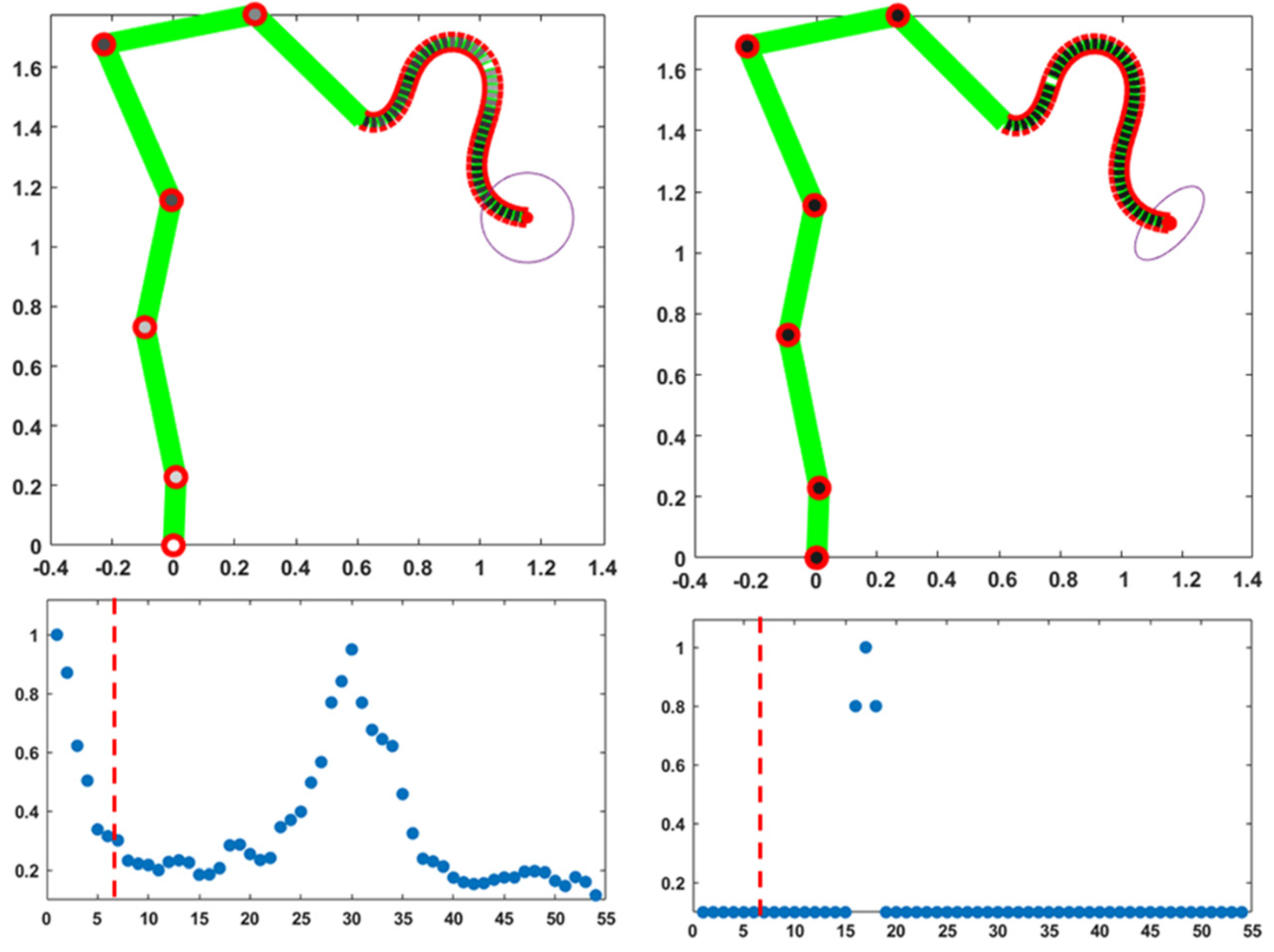
Figure 5 refers to the problem of modulating, at the end of a gesture, the compliance vector of the body model in such a way to implement specific features of the compliance ellipse: such features, e.g. the degree of roundness or the orientation, may be required for the stability or the accuracy of the interaction of the trunk-tip with the environment or a manipulated object. The stiffness ellipse characterizes the geometrical aspects of the interaction, namely the relation between incremental relative motions and interaction force vectors. In the case of human movements, achieving a desired compliance ellipse is equivalent to selecting an appropriate pattern of coactivation of all the DoFs, on top of a distribution of activities that maintains the same equilibrium point [23]: it is suggested that a similar mechanism may apply to hybrid trunk-like robots. In the implemented version of the PMP model, the compliance vector is normalized thus producing a compliance ellipse of normalized size. The size of the ellipse, without affecting its shape, can be changed by applying a gain to all the elements of the compliance vector. The shape of the ellipse is selected as explained in the methods.
In particular, the left part of Figure 5 displays the activation of the compliance vector for achieving a round ellipse, i.e. an isotropic elastic behavior, according to which the elastic resistance force is always collinear with a corresponding positional displacement and with the same amplitude, whatever the direction of the disturbance. The bottom graph on the left part of the figure shows that this solution is obtained with a coordinated modulation of the compliance of all the DoFs of both segments of the kinematic chain, namely the skeletal and the hydrostatic part. In particular, the pattern of modulation of the hydrostatic part, which is characterized by a well-marked peak approximately in the middle of the trunk, reminds the pattern of modulation typical of pseudo-skeletal articulation of the hydrostat (illustrated in Figure 4), a single pseudo-joint in this case. It is also worth noting that such peak of activity in the hydrostatic segment is associated with a peak of activity of the initial joints of the skeletal segment, enhancing the cooperation of the two parts of the body schema implicitly carried out by the PMP model. As explained in the methods, the modulation of the compliance vector capable to induce a quasi-round compliance ellipse is obtained by a simple based gradient descent process that minimizes the roundness indicator of the compliance ellipse: a few hundred steps were necessary for obtaining the result in the figure. In general, the optimal compliance pattern for a quasi-round compliance ellipse is a function of the posture at contact. A sub-optimal strategy, for avoiding a real-time computation immediately after the end of a reaching movement, may be based on a memorization of the compliance patterns for frequently experienced posture and a related interpolation for the posture at play.
The right part of Figure 5 focuses on the computation of the compliance vector characterized by the fact that the orientation of the compliance ellipse approximately matches a desired angle, in agreement with the shape and physical properties of the manipulated object. In this particular example, the desired orientation is 45 deg: the solution easily found in this case is the identification of a pseudo-joint in the trunk such that small incremental rotations around the joint displace the end-effector along the desired angle. The pseudo-joint is computed by tracing a line from the end-effector, perpendicular to the required orientation of the ellipse, and selecting the DoF of the kinematic chain that is mostly collinear with the traced line. The selected DoF is assigned a maximum compliance value and all the other DoFs are frozen, as shown in the bottom graph in the right part of Figure 5: this is equivalent to tuning the compliance vector for simulating the best one-joint segmentation of the kinematic chain. If no DoF is sufficiently aligned with the traced line, it is possible to adopt a minimization strategy similar to the one applied for achieving a round ellipse. For example, it is possible to identify the pair of DoFs that are best aligned with the specified direction and then use the pair of compliance parameters for guiding the gradient descent: according to this strategy; all the other joints should be frozen and this is equivalent to tuning the compliance vector for simulating the best two-joints segmentation of the kinematic chain. In any case, after having reached the target point using a specific assignment of the compliance vector, it is possible to evaluate immediately the orientation of the compliance ellipse for that posture, by computing the eigenvector related to the higher eigenvalue of the compliance matrix (equation 2), and evaluate if that orientation matches at least approximately the expected interaction patterns.
4. Discussion and Conclusions
Soft robots are made from soft materials, instead of hard ones, such as silicone, rubbers, and gels, structured in such a way to allow controlling the shape, similarly to living hydrostats as octopus tentacles or elephant trunks [24,25]: both types of hydrostats do not have bones but can stiffen up, when needed, for a variety of dexterous behaviors as to grab food or use tools [26]. The elephant’s trunk is a complex network composed of tens of thousands of bundles of muscle fibers, which work together by relaxing and contracting to produce forces that shape the trunk, driving the trunk-tip to target [27,28]. Although trunks do not have any bone or semi-hard cartilage, the motor dexterity of elephants depends on the close sensory-motor-cognitive integration between the soft hydrostatic part and the articulated skeletal part; in contrast, this requirement is irrelevant for the octopus because it is not a terrestrial animal. Thus, for a large part of foreseeable applications that may involve soft robots, the choice should aim to hybrid systems that combine a soft and a hard subsystem, with a hyper-redundant kinematic capability. The motivation for conceiving soft or hybrid robots emerged recently from considerations of the limitations of traditional industrial robots in negotiating natural environments, in the general framework of a bioinspired evolution of service robotics with a high degree of human-robot interaction and an embodied cognitive approach [24,29].
In this study it is shown how the PMP computational model is naturally compatible with hybrid robotic systems, integrating the soft and the hard components in a common computational framework, independent of the specific technology used for the soft part. As explained in the methods, such computational framework is fundamentally force-based and we may observe that for a large family of experimental soft robots the design and control technologies are force-based as well: consider, for example, a method called jamming [30,31,32], namely a process for enabling controllable stiffness and inducing shape change in soft robotics, in which granular materials in the trunk-like arm are packed together to change its stiffness, or the soft origami modular (SOM) segment concept [33]. In contrast, traditional rigid robots for industrial applications are mostly position controlled.
We should also observe that the PMP approach is force-based for both the soft and rigid components, whatever the degree of redundancy of the robot kinematic schema, thus providing a natural integration framework of the two subsystems. Moreover, the PMP approach provides a rational and natural method for modulating the overall stiffness of the hybrid robot performance in a functional manner: for example, a compliant, flexible state is appropriate for delicate tasks and for assuring the safety of interacting people around the robot; on the other hand, a more rigid state for carefully selected segments of the kinematic chain is helpful when dealing with heavy loads and challenging tasks.
In general, a crucial role of stiffness is related to the difficulties engendered by contact tasks that require intimate dynamic interaction between the robot and its environment: that interaction changes the performance of the robot and can jeopardize the stability of its control system. Contact stability may be guaranteed if the control system provides the manipulator with an appropriately structured dynamic response to environmental inputs, characterized as impedance control [34,35].
Generally speaking, trunk-like soft arms may exhibit high dexterity and adaptability very similar to the elephants. However, owing to the continuum and soft bodies, their performance in payload and spatial movements is limited, although numerous preliminary results have been achieved in soft robotic applications, e.g. for manipulation [36,37] and grasping [38]. Moreover, the transition from laboratory prototypes to real-world applications requires a deeper understanding of the limits of the current approaches in terms of materials, design principles and related control methodologies.
In conclusion, we suggest that the computational approach investigated in this study is fundamentally independent of the specific technological choices, providing general principles of synergy formation and compliance modulation that may help consolidate the emergence of hybrid robot technologies.
Appendix A
The kinematic chain used in the simulation for representing a planar, hybrid kinematic chain, consisting of a skeletal-based component with 6 DoFs and a trunk-like component with 48 DoFs, is characterized as follows.

| Lengths (in cm) of the six links of the skeletal part (from the foot to the trunk) | |||||
|---|---|---|---|---|---|
| L1 | L2 | L3 | L4 | L5 | L6 |
| 22.9 | 51.2 | 43.4 | 56.6 | 50.3 | 49.7 |
| Range of motion (in deg) of the corresponding DoFs | |||||
|---|---|---|---|---|---|
| q1 | q2 | q3 | q4 | q5 | q6 |
| 0 : +180 | -45 : +45 | -45 : +45 | -45 : +45 | -120 : 0 | -90 : 0 |
The length of the 48 modules of the trunk part () is 2.5 cm; the range of motion of the corresponding DoFs is -45:+45 deg.
The Jacobian matrix has 2 rows and n=54 columns. The columns are computed recursively in a backward order, from the trunk tip to the skeleton ankle:
where .
References
- Jeannerod, M. Neural simulation of action: a unifying mechanism for motor cognition. Neuroimage 2001, 14, S103–S109. [Google Scholar] [CrossRef] [PubMed]
- Vernon, D.; Beetz, M.; Sandini, G. Prospection in cognitive robotics: The case for joint episodic-procedural memory. Front. Robot. AI 2015, 2, 19. [Google Scholar] [CrossRef]
- Sandini, G.; Sciutti, A.; Morasso, P. Artificial Cognition vs. Artificial Intelligence for Next-Generation Autonomous Robotic Agents. Front. Comput. Neurosci. 2024, 18, 1349408. [Google Scholar] [CrossRef]
- Gilbert, D.; Wilson, T. Prospection: Experiencing the future. Science 2007, 351, 1351–1354. [Google Scholar] [CrossRef]
- O'Connell, C. (2007). The Elephant's Secret Sense: The Hidden Lives of the Wild Herds of Africa. Simon & Schuster, New York City, USA, 2007; pp. 174–184. ISBN 978-0-7432-8441-7.
- Wilson, J.F.; Mahajan, U.; Wainwright, S.A.; Croner, L.J. A continuum model of elephant trunks. J. Biomech. Eng. 1991, 79, 79–84. [Google Scholar] [CrossRef]
- Hart, B.L.; Hart, L.A.; McCoy, M.; Sarath, C.R. Cognitive behaviour in Asian elephants: use and modification of branches for fly switching. Animal Behaviour 2001, 62, 839–847. [Google Scholar] [CrossRef]
- Dagenais, P.; Hensman, S.; Haechler, V.; Milinkovitch, M.C. Elephants evolved strategies reducing the biomechanical complexity of their trunk. Curr. Biol. 2021, 31, 4727–4737. [Google Scholar] [CrossRef] [PubMed]
- Morasso, P. Neural Simulation of Actions for Serpentine Robots. Robots. Biomimetics 2001, 9, 416. [Google Scholar] [CrossRef]
- Johansson, G. Visual perception of biological motion and a model for its analysis. Percept. Psychophys 1973, 14, 201–211. [Google Scholar] [CrossRef]
- Morasso, P. A vexing question in motor control: the degrees of freedom problem. Front. Bioeng. Biotechnol, 2022; 9, 783501. [Google Scholar] [CrossRef]
- Mussa Ivaldi, F.A.; Morasso, P.; Zaccaria, R. Kinematic networks. A distributed model for representing and regularizing motor redundancy. Biol. Cybern. 1988, 60, 1–16. [Google Scholar] [CrossRef]
- Mussa Ivaldi, F.A.; Hogan, N.; Bizzi, E. Neural, mechanical, and geometric factors subserving arm posture in humans. J. Neurosci. 1985, 5, 2732–2743. [Google Scholar] [CrossRef] [PubMed]
- Renda, F.; Boyer, F.; Dias, J.; Seneviratne, L. Discrete Cosserat approach for multisection soft manipulator dynamics. IEEE Trans. Robot. 2018, 34, 1518–1533. [Google Scholar] [CrossRef]
- Cosserat, E.; Cosserat, F. Théorie des corps déformables 1909, Paris, France, published 09-04-2009 by Hermann Archives; Collection : Philosophie, Politique et Économie - Sciences et Technique; ISBN : 9782705669201.
- Altenbach, H.; Bîrsan, M.; Eremeyev, V.A. Cosserat-Type Rods. In: Altenbach, H., Eremeyev, V.A. (eds) Generalized Continua from the Theory to Engineering Applications. 2013, CISM International Centre for Mechanical Sciences, vol 541. Springer, Vienna. [CrossRef]
- McCarthy, J.M. Introduction to Theoretical Kinematics, 1990. MIT Press, Cambridge, MA, USA. ISBN 978-0-262-13252-7.
- Benhabib, B.; Goldenberg, A.A.; Fenton, R.G. A solution to the inverse kinematics of redundant manipulators. J. Robot. Syst. 1985, 2, 373–385. [Google Scholar] [CrossRef]
- Zhao, Y.; Zhang, Y.; Li, J.; Jin, L.; He, J.; Zhang, X.; Lu, X. Inverse displacement analysis of a hyper-redundant bionic trunk-like robot. Int. J. Adv. Robot. Syst. 2020, 17, 1729881420903223. [Google Scholar] [CrossRef]
- Morasso, P. (2022) A vexing question in motor control: the degrees of freedom problem. Front. Bioeng. Biotechnol. 2022, 9, 783501. [Google Scholar] [CrossRef]
- Bizzi, E.; Accornero, N.; Chapple, W.; Hogan, N. Posture Control and Trajectory Formation during Arm Movement. J. Neurosci. 1984, 4, 2738–2744. [Google Scholar] [CrossRef]
- Shadmehr, R.; Mussa-Ivaldi, F.; Bizzi, E. Postural force fields of the human arm and their role in generating multijoint ovements. J. Neurosci. 1993, 13, 45–62. [Google Scholar] [CrossRef]
- Tsuji, T.; Morasso, P.; Goto, K.; Ito, K. Human hand impedance characteristics during maintained posture. Biol Cybern. 1995, 72, 475–85. [Google Scholar] [CrossRef]
- Kim, S.; Laschi, C.; Trimmer, B. Soft robotics: a bioinspired evolution in robotics. Trends Biotechnol. 2013, 31, 287–294. [Google Scholar] [CrossRef]
- Yasa, O.; Toshimitsu, Y.; Michelis, M.Y.; Jones, L.S.; Filippi, M.; Buchner, T.; Katzschmann, R.K. An overview of soft robotics. Ann. Rev. Control, Robotics, & Aut. Sys. 2023, 6, 1–29. [Google Scholar] [CrossRef]
- Chevalier-Skolnikoff, S.; Liska, J. Tool use by wild and captive elephants. Animal Behav. 1993, 46, 209–219. [Google Scholar] [CrossRef]
- Longren, L.L.; Eigen, L.; Shubitidze, A.; Lieschnegg, O.; Baum, D.; Nyakatura, J.A.; et al. Dense reconstruction of elephant trunk musculature. Curr. Biol. 2023, 33, 4713–4720. [Google Scholar] [CrossRef] [PubMed]
- Kelasidi, E.; Tzes, A. Serpentine motion control of snake robots for curvature and heading based trajectory – parameterization. 20th Mediterranean Conference on Control & Automation (MED), Barcelona, Spain, 2012, 536-541. [CrossRef]
- Pfeifer, R.; Lungarella, M.; Iida, F. Self-organization, embodiment, and biologically inspired robotics. Science 2007, 318, 1088–1093. [Google Scholar] [CrossRef]
- Manti, M.; Cacucciolo, V.; Cianchetti, M. Stiffening in soft robotics: a review of the state of the art. IEEE Robot. Autom. Magaz. 2016, 23, 93–106. [Google Scholar] [CrossRef]
- Fitzgerald, S.G.; Delaney, G.W.; Howard, D. 2020. A review of jamming actuation in soft robotics. Actuators 2020, 9, 104. [Google Scholar] [CrossRef]
- Lois, L.; Howard, G.D. Jellyphant: A Soft, Elephant Trunk-Inspired Robotic Arm That Can Grab Objects. Frontiers for Young Minds 2024, 12, 1341887. [Google Scholar] [CrossRef]
- Tang, S.; Tang, K.; Wu, S.; Xiao, Y.; Liu, S.; Yi, J.; Wang, Z. Performance enhancement of the soft robotic segment for a trunk-like arm. Front. Robot. AI 2023, 10, 1210217. [Google Scholar] [CrossRef]
- Hogan, N. Impedance Control: An Approach to Manipulation. 1984 American Control Conference, San Diego, CA, USA, 1984, 304-313. [CrossRef]
- Hogan, N. On the stability of manipulators performing contact tasks. IEEE J. Robotics and Automation 1988, 4, 677–686. [Google Scholar] [CrossRef]
- Hannan, M.W.; Walker, I.D. Kinematics and the implementation of an elephant’s trunk manipulator and other continuum style robots. J. Robotic Syst. 2003, 20, 45–63. [Google Scholar] [CrossRef]
- Bao, G.; Chen, L.; Zhang, Y.; Cai, S.; Xu, F.; Yang, Q.; et al. Trunk like soft actuator: Design, modeling, and experiments. Robotica 2020, 38, 1–15. [Google Scholar] [CrossRef]
- Wang, W.; Meng, H.; Bao, G. Design and Modeling of a Continuous Soft Robot. In: Yu, H., Liu, J., Liu, L., Ju, Z., Liu, Y., Zhou, D., Eds.; Intelligent Robotics and Applications. ICIRA 2019. Lecture Notes in Computer Science, 11740. Springer, Cham. [CrossRef]
Figure 1.
PMP computational model for synergy formation and compliance modulation of a hybrid kinematic chain with a skeletal segment and a hydrostatic segment.
Figure 1.
PMP computational model for synergy formation and compliance modulation of a hybrid kinematic chain with a skeletal segment and a hydrostatic segment.
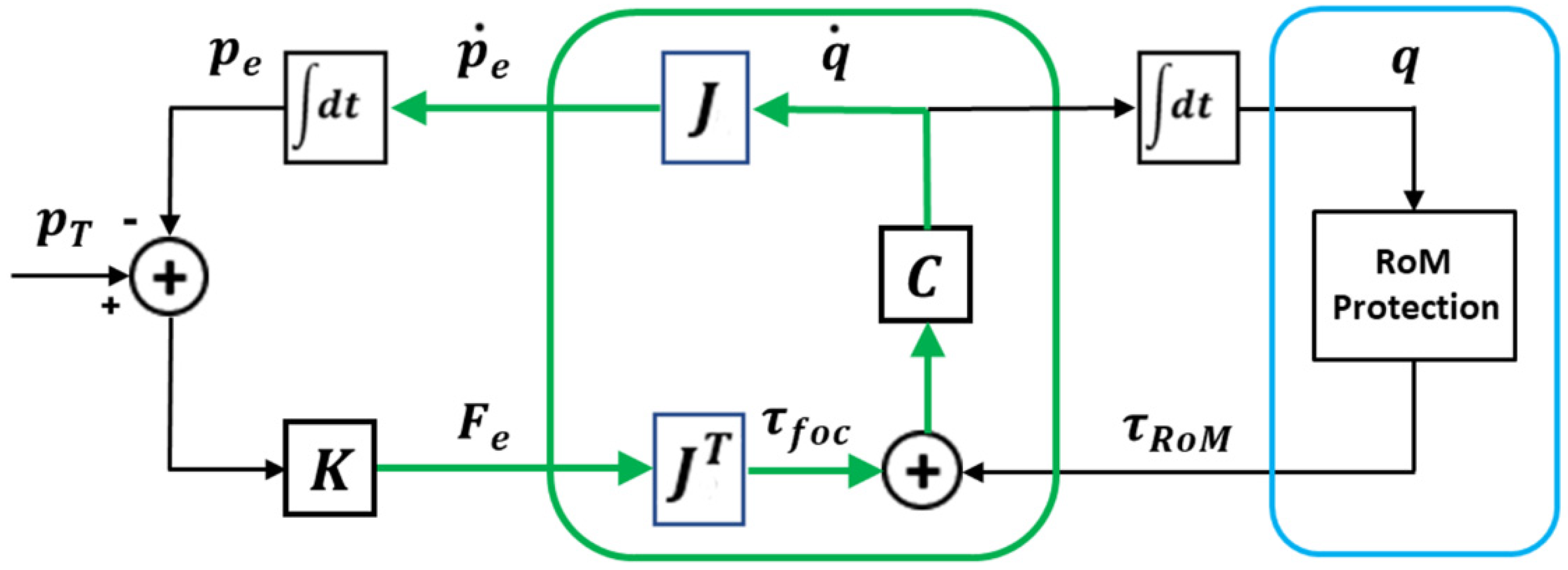
Figure 2.
Two simulations of a point-to-point upward-moving reaching gesture (measurement units are meters for both axes), related to slightly different distribution of the compliance vector, illustrated in the two bottom panels: the 54 elements of the normalized vector are ordered, the skeletal part first (the first 6 elements from foot to shoulder) followed by the hydrostatic part (the following 48 elements from the trunk base to the trunk tip). The dashed red line separates the DoFs of the skeletal segment from the DoFs of the hydrostatic segment. In the two top panel the same compliance values are visualized with a color code according to the grayscale palette.
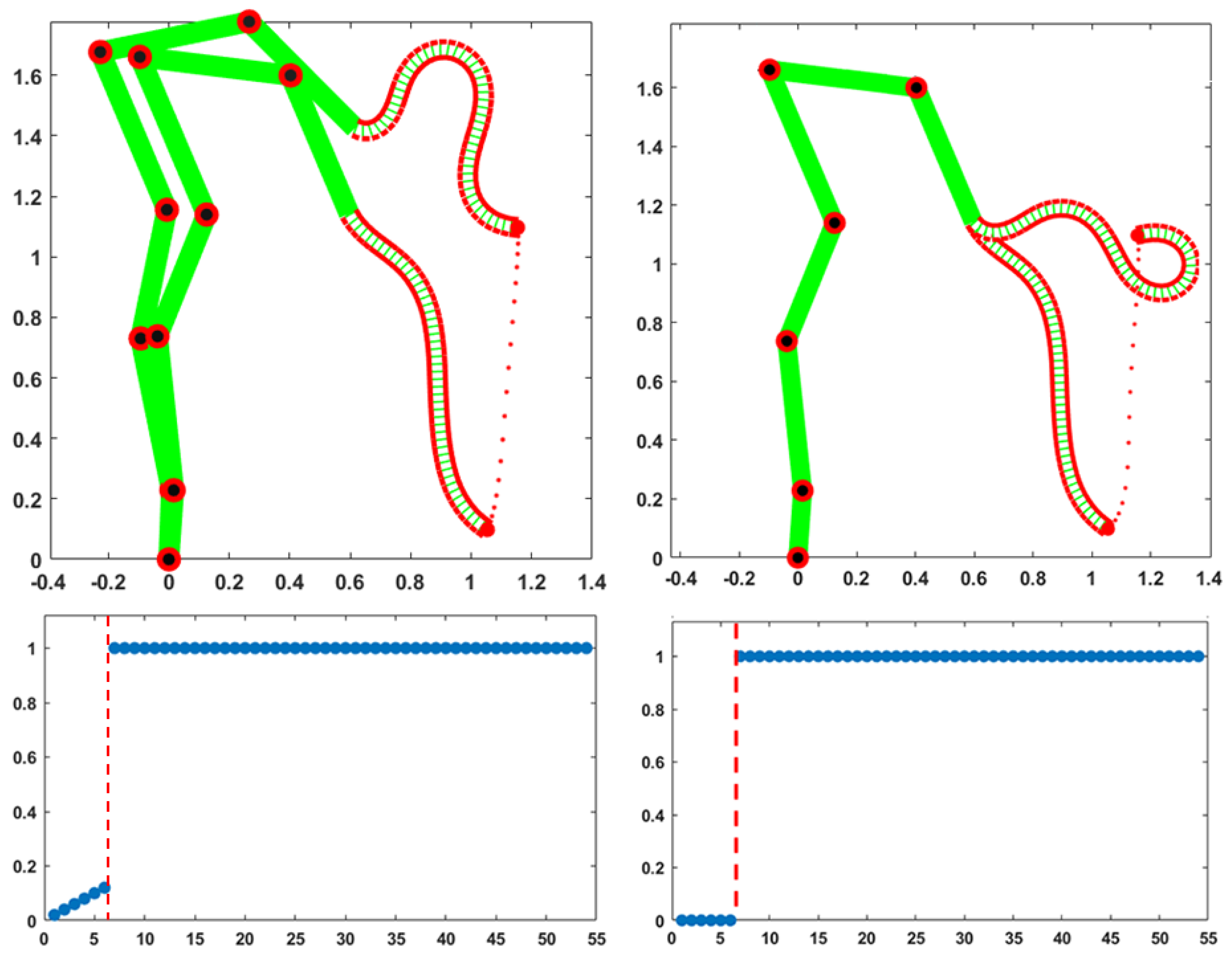
Figure 3.
The left/right parts of the figure refer to the gesture of the left/right parts of Figure 2. For each column the top graph shows the time course of the 48 DoFs of the trunk; the measurement units are ms, for the time axis, and deg, for the vertical axis; the two red horizontal lines identify the RoM of the trunk DoFs (±30 deg). The bottom graphs show the evolution of the trunk curvature profile (measurement unit m-1, from the trunk base to the trunk tip) during the corresponding gesture, from the initial to the final instant of the movement.
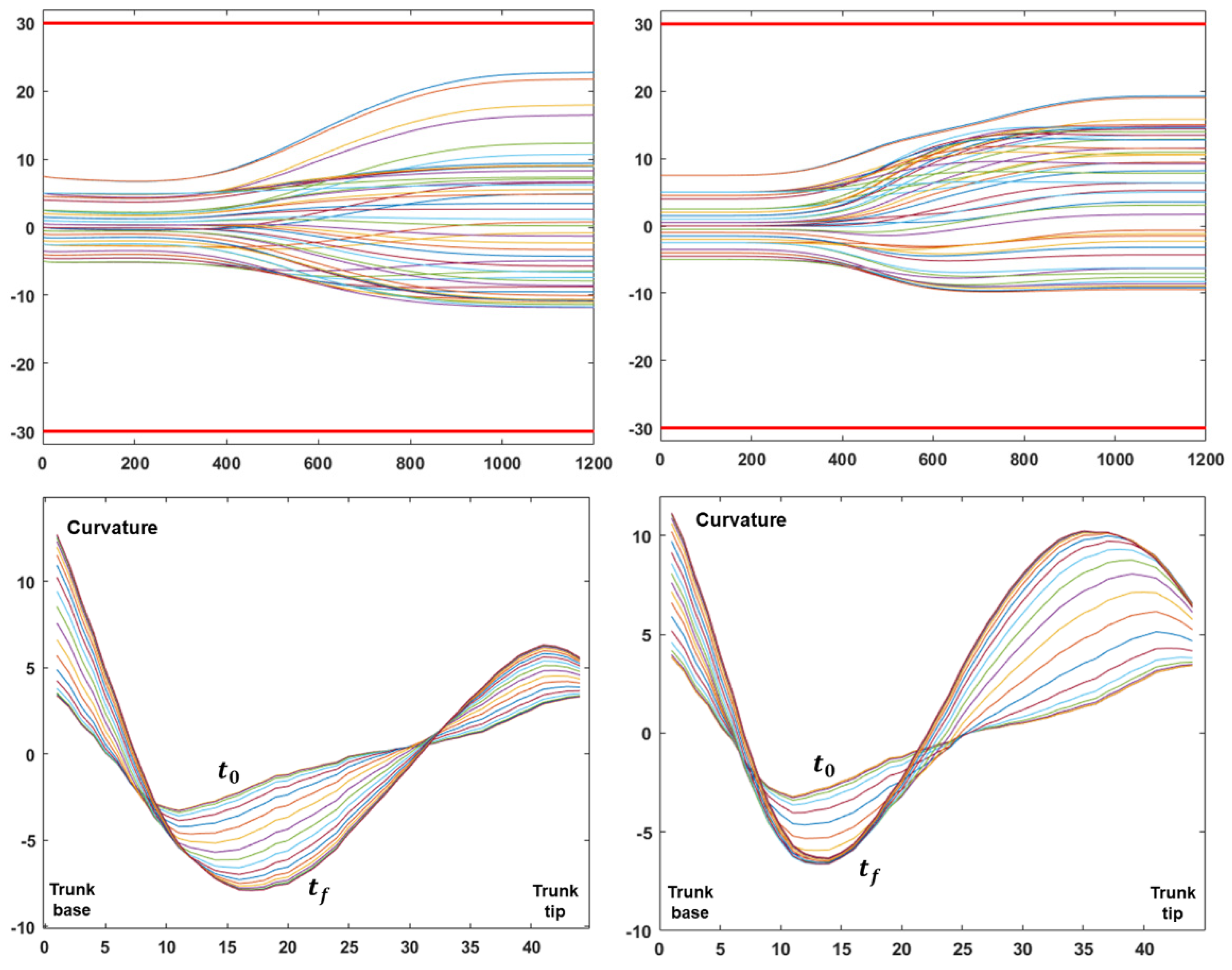
Figure 4.
The two columns of graphs illustrate two simulations of a point-to-point upward-moving gesture with the same initial posture and final position of the trunk-tip but with different compliance vectors of the trunk segment. In the left column the vector of the trunk is set to simulate a skeletal articulation with 2 pseudo-joints and 3 rigid segments. In the left column the skeletal articulation of the trunk has 3 pseudo-joints and 4 rigid segments. The top row of graphs shows the initial and final body postures and the trajectory of the trunk-tip (measurement unit meters for both axes). The corresponding compliance vectors are plotted in the middle row of graphs: 54 DoFs, ordered from foot to trunk-tip; the compliance vectors are also visualized in the top row of graphs with a color code according to the grayscale palette. The bottom row of graphs plots the time course of the 48 DoFs of the trunk (measurement unit ms, for the time axis, and deg, for the vertical axis); the red horizontal lines identify the RoM of the trunk DoFs.
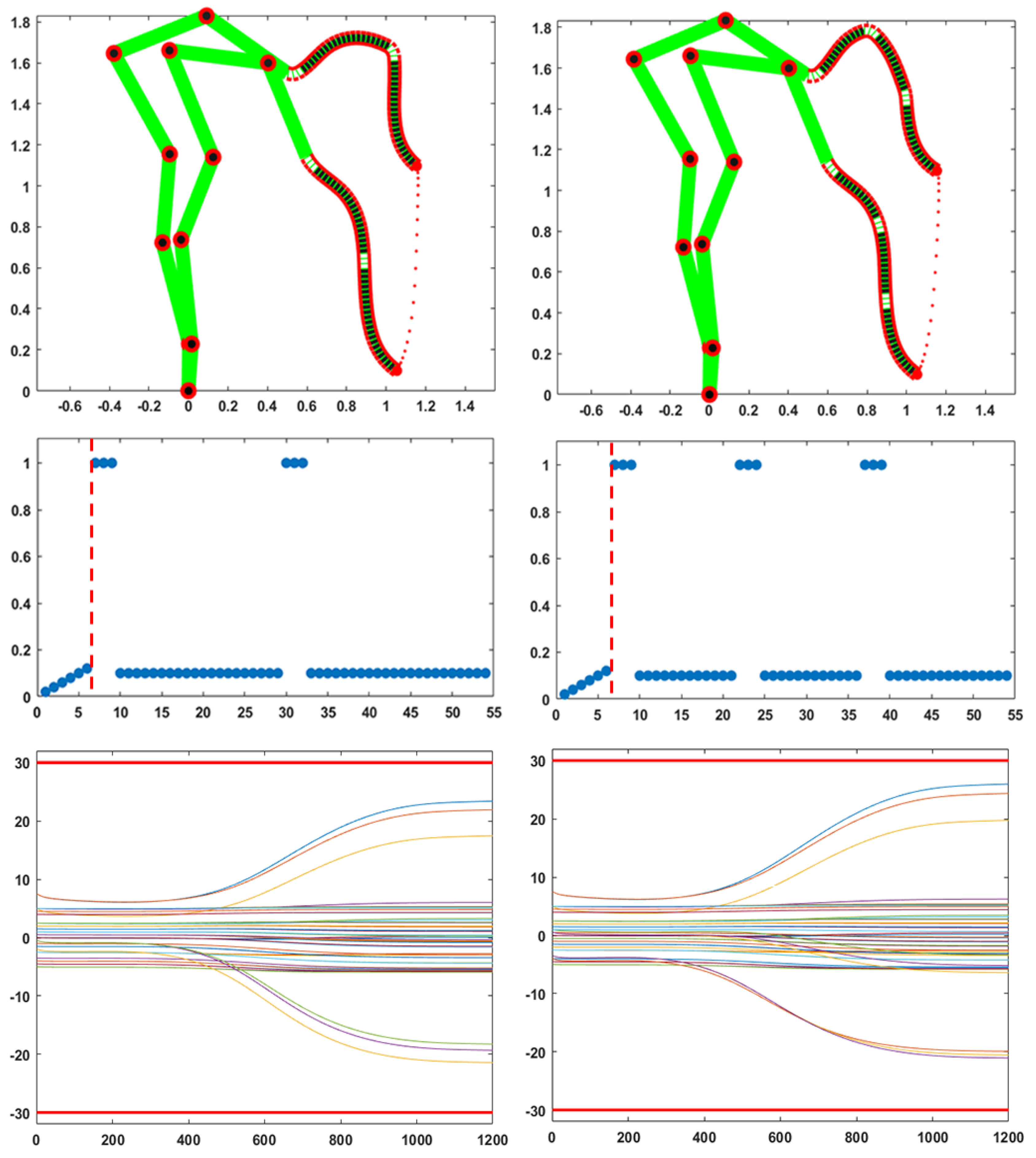
Figure 5.
Modulation of the compliance vector for achieving a desired compliance ellipse of the end-effector, for a posture achieved at the end of a reaching movement. The left column of graphs refers to the a desired round ellipse; the right column to an ellipse oriented according to a 30 deg angle. The corresponding compliance vectors are plotted in the bottom row of graphs: both graphs show the normalized compliance values of the 54 DoFs of the model, ordered from the foot to the trunk tip. The same compliance values are visualized in the top row of graphs with a color code according to the grayscale palette. The dashed red line separates the DoFs of the skeletal segment from the DoFs of the hydrostatic segment. The stiffness ellipses corresponding to the plotted values of the compliance vector are visualized around the trunk-tip.
Disclaimer/Publisher’s Note: The statements, opinions and data contained in all publications are solely those of the individual author(s) and contributor(s) and not of MDPI and/or the editor(s). MDPI and/or the editor(s) disclaim responsibility for any injury to people or property resulting from any ideas, methods, instructions or products referred to in the content. |
© 2024 by the authors. Licensee MDPI, Basel, Switzerland. This article is an open access article distributed under the terms and conditions of the Creative Commons Attribution (CC BY) license (http://creativecommons.org/licenses/by/4.0/).
Copyright: This open access article is published under a Creative Commons CC BY 4.0 license, which permit the free download, distribution, and reuse, provided that the author and preprint are cited in any reuse.


