
Submitted:
30 October 2024
Posted:
31 October 2024
You are already at the latest version
Abstract
A reinforcement learning control method for a solid attitude and divert propulsion system is proposed. The system in this research includes 4 divert thrust nozzles, 6 attitude thrust nozzles, and a common combustion chamber. To achieve the required thrust, the pressure in the combustion chamber is first adjusted by controlling the total opening of the nozzles to generate the gas source. Next, by controlling the opening of nozzles at different positions, the required thrust is produced in five-axis directions. Finally, the motor speed is regulated to drive the valve core to the specified position, completing the closed-loop control of the nozzle opening. The control algorithm used is the Proximal Policy Optimization (PPO) reinforcement learning algorithm. Through system identification and numerical modeling, the training environment for the intelligent agent is created. To accommodate different training objectives, multiple reward functions are implemented. Ultimately, through training, a multi-layer intelligent agent architecture for pressure, thrust, and nozzle opening is established, achieving effective system pressure and thrust control.
Keywords:
Solid propulsion system
; Attitude and divert nozzles
; Thrust and pressure control
; Reinforcement learning
1. Introduction
The Attitude and Divert Propulsion System (ADPS) is a propulsion system in aerospace engineering designed to adjust spacecraft attitude, ensuring three-axis stability and enabling orbital maneuvers [1]. ADPS functions by ejecting gas through multiple nozzles: attitude thrust nozzles at the spacecraft's rear control pitch, yaw, and roll, while divert thrust nozzles at the center of mass provide lateral thrust [2]. ADPS types include the liquid attitude and divert propulsion system (LADPS) and the solid attitude and divert propulsion system (SADPS), each with specific advantages and disadvantages tailored to particular spacecraft design objectives and performance requirements [3].The LADPS uses liquid oxidizer and fuel as propellants, allowing for repeated thrust start and stop and providing a higher specific impulse. However, it requires complex fuel storage and delivery systems that need regular maintenance [4]. In contrast, the SADPS uses solid oxidizers and fuels, which eliminates the need for complex pipeline delivery systems, offering ease of maintenance, safety, and storage. Variable thrust in SADPS is achieved by altering the throat area of the nozzle in real-time [5]. Precise control of nozzle openings and the propellant combustion rate enables pressure and thrust regulation in the combustion chamber [6]. However, the shared combustion chamber among multiple nozzles and the pressure-dependent combustion rate result in a gradual increase in free volume, necessitating intricate control algorithms for safe and reliable operation.
The dynamics of the Solid Attitude and Divert Propulsion System (SADPS) are characterized by nonlinear and time-varying behavior due to nozzle control, pressure regulation, and thrust management. These characteristics make traditional control methods like Proportional Integral Derivative (PID) inadequate for meeting performance standards [7]. Sergio's review examines closed-loop pressure control methods in rocket propulsion, typically using linearized models around specific operating points to derive steady-state controllers, predominantly of the PID type. Sergio emphasizes that future control strategies must robustly achieve the desired thrust levels. Potential solutions include enhanced nonlinear approaches and optimal closed-loop control [8]. Ming Zhu designed a pressure control system for pintle solid rocket motors using parameter identification through adaptive control methods, demonstrating significant advantages in terms of stability, robustness, and precision [9]. Bergmans and Di Salvo introduced an adaptive matching technique that adjusts pre-designed controllers based on evolving system dynamics [10], while Joner and Quinquis proposed adaptive controllers to mitigate uncertainty effects [11]. Waxenegger-Wilfing proposed a data-driven method for early warning of thermoacoustic instabilities in rocket engine thrust chambers, successfully using machine learning to predict these instabilities in advance [12]. Previous research extensively investigated spacecraft propulsion, aiming to minimize fuel consumption for effective thrust command allocation and stable attitude control [13,14,15]. Lee and Lim applied adaptive feedback linearization techniques to achieve pressure regulation and conducted extensive work on five-axis thrust distribution [16,17,18].
The integration of artificial intelligence into control systems has led to significant advancements, with Reinforcement Learning (RL) emerging as a prominent approach for addressing sequential decision problems [19]. RL offers advantages such as learning from experience, flexibility, autonomous decision-making, robustness, and resource efficiency [20]. The development of an RL-based mission planning strategy for a Partial Space Elevator (PSE) addresses the challenge of maintaining the main satellite’s orbital stability during climber operations, demonstrating that using a deep Q-network to optimize the waiting intervals between transfer missions can minimize orbital radius changes effectively [21]. Skarka’s [22] review explores the application of Machine Learning (ML) and RL techniques in enhancing the navigation and obstacle avoidance capabilities of Unmanned Aerial Vehicles (UAVs), revealing the effectiveness of various RL algorithms in enabling autonomous navigation through real-time environmental interactions. Additionally, Pham’s [23] research introduces an RL framework for robotic manipulators to adapt to joint malfunctions during tasks, achieving a high success rate of 93.6% in diverse failure conditions. Furthermore, a proposed trajectory tracking control algorithm for Unmanned Surface Vehicles (USVs) employs an improved Deep Deterministic Policy Gradient (DDPG) method [24], demonstrating its effectiveness in dynamic ocean environments through experimental validation.”
In aerospace vehicle control, RL has demonstrated potential in addressing complex and uncertain environments, enhancing autonomous decision-making capabilities, and handling nonlinear control problems. However, there is a lack of literature on the application of RL in aerospace propulsion systems. Leveraging RL, we developed an intelligent control method and architecture for the Solid Attitude and Divert Propulsion System (SADPS). Considering the system's strong non-linearity, multiple inputs and outputs, disturbances, and coupling characteristics, we established a multi-agent architecture for pressure, thrust, and nozzle opening control. We devised an adaptive reward function and trained an expert neural network, demonstrating superior control effects compared to PID. Simulation tests validated the effectiveness of the intelligent control method.
2. Model and Algorithm
2.1. Solid Attitude and Divert Propulsion System (SADPS)
As shown in Figure 1, the four divert thrust nozzles are arranged at the spacecraft's center of mass, generating thrust in the y-axis and z-axis directions. Additionally, six attitude thrust nozzles are positioned at a certain distance from the center of mass, providing pitch, yaw, and roll control along the three axes.
The SADPS operates in three modes: power-saving mode, performance mode, and overload mode.
- Performance mode (Figure 2) requires a medium level of thrust to adjust the spacecraft's orbit and pitch angle.
- Power-saving mode minimizes propellant loss by reducing pressure as much as possible while maintaining flight attitude and compensating for gravity.
- Overload mode necessitates rapid changes in the spacecraft's trajectory and flight attitude.
Typically, chamber pressure levels are set to constant values to ensure stability and predictability in performance.
Figure 2.
Three operating states of the solid attitude and divert propulsion system.
From time t0 to t1, the SADPS operates in performance mode, during which the spacecraft adjusts its attitude and changes its orbit to aim at the target. From time t1 to t2, the SADPS switches to power-saving mode, maintaining orbital altitude and overcoming Earth's gravity. From time t2 to t3, the engine enters overload mode, performing the final rapid maneuvers to correct any deviation from the target.
The control system model is depicted in Figure 3. The gas generator primarily produces the working medium required for thrust. The hot gas can be expelled simultaneously through four divert thrust nozzles and six attitude thrust nozzles. The pressure controller regulates the gas generator’s pressure and provides the total opening command for the nozzles. The thrust controller allocates the opening of different nozzles and, within the constraints of the total nozzle opening, generates the required five-axis thrust. The opening controller drives the motor to rotate according to each valve’s opening instructions, completing the closed loop of nozzle operation. Through the coordinated hierarchical work of the three controllers, the switching of the engine’s operating modes and the output of thrust are achieved.
Each nozzle's aperture size is adjusted by a throat plug-type gas valve. This valve comprises a plug-shaped element located in the center of the valve throat. When this element interacts with the inner wall of the nozzle, it forms an annular gas channel known as the equivalent throat area. By altering the position of the throat plug, the equivalent throat area is adjusted, thereby controlling the nozzle's output thrust [25]. The throat plug regulating valve consists of several components, including a brushless DC motor, a decelerator, a valve body, a nozzle, thermal protection components, and transmission components. The throat plug is driven by the rotary motor through a rotary-to-linear transmission mechanism, causing it to reciprocate horizontally.
2.2. Reinforcement Learning Trainer
The PPO algorithm consists of three neural networks: Actorlearn, Actorchoose,and Critic. It aims to improve strategy actions by computing action mean and variance, then selecting the final action via random sampling. Advantage clipping limits strategy updates to ensure robustness [26]. The basic PPO structure is shown in Figure 4.
The chooses action based on the st and receives reward. The evaluates state values Vt and output TD error. During updates, is backpropagated and clipped within the range (1−ε,1+ε) to refine both the Critic and Actorlearn networks. Periodically, the Actorlearn parameters are copied to Actorchoose for better action selection.
To accelerate training, we applied several techniques to improve the efficiency of PPO:
- Network Simplification: Replaced neural network hidden layers of widths 256 and 128 with widths 64 and 64, reducing parameters by 87% and inference time by over 20% without compromising control effectiveness.
- Generalized Advantage Estimation [27]: Utilized generalized advantage estimation during network weight updates. Calculating the mean and variance of the advantage function across the entire batch made the training process smoother and more stable.
- Learning Rate Adjustment: Set initial learning rates for the Actor and Critic to 1e-4 and 3e-4, respectively. Reduced them exponentially by an order of magnitude over 1000 training epochs for more stable convergence.
- Random Initialization and Gradient Clipping: Initialized network parameters with samples from a standard normal distribution and applied gradient clipping once before updating the network.
- Activation Function Change [28]: Replaced ReLU with Tanh in the hidden layers to avoid the vanishing gradient problem associated with negative values.
2.3. Training Environment
2.3.1. Chamber Pressure Dynamics
To regulate pressure, a combustion chamber pressure dynamics model is established for training the pressure control agent. The pressure-throat area relationship in a solid rocket motor is described by a zero-dimensional internal ballistic equation [29]:
Here, Vc, c*, and k denote the combustion chamber free volume, characteristic velocity, and heat capacity ratio of the gas, respectively. Ab and ρp represent the burning area and density of the propellant, and the burning rate is given by aPcn, where Pc is the chamber pressure. The term Atsum denotes the total nozzle opening. Typically, once the propellant grain shape of the engine is confirmed, the thickness of the burned propellant can describe the variation of Vc and Ab. By modifying Ab, it is possible to simulate the dynamic process inside the combustion chamber using numerical solution methods, thereby creating a training environment for the pressure agent. In this study, we employed the fourth-order Runge-Kutta method to solve the equations.
2.3.2. Five-Axis Thrust Calculation
In Figure 5(a), divert nozzles produce lateral acceleration by thrusting at the spacecraft's center of mass, typically in the range of hundreds to thousands of newtons. This allows for rapid orbital adjustments without attitude changes. Nozzles 0 and 2 act in the z-axis, while nozzles 1 and 3 act in the y-axis.
Fig.5(b) illustrates attitude control nozzles at the spacecraft's tail, exerting tens to hundreds of newtons. Nozzles 4 and 7 induce clockwise rolling, while nozzles 5 and 6 induce counterclockwise rolling. Nozzles 4 and 5 pitch up, nozzles 6 and 7 pitch down, nozzle 8 causes left yaw, and nozzle 9 causes right yaw.
The equations for the synthesis of thrust in five-axis direction are as follows:
y-axis thrust:
z-axis thrust:
yaw-axis thrust:
pitch-axis Thrust:
roll-axis Thrust:
The thrust generated by each nozzle can be calculated according to the thrust calculation Equation. The thrust can be expressed as the product of the thrust coefficient Cf , pressure Pc, and the throat area At.
2.3.3. Valve Servo Motion
Achieving closed-loop control of nozzle opening by regulating the valve core position is crucial. Modeling the dynamic behavior of the valve accurately is challenging due to the presence of various mechanical components and frictional forces within the gas valve. To address this, we employ system identification techniques to tailor the servo system.
We establish a fourth-order state-space model, achieving a system similarity of 92.1%. The identified observable state space is represented in Equation (8):
where x(t) denotes an n-dimensional state vector, A is the system matrix, B represents the control matrix, denotes the speed command, C stands for the output matrix, D indicates the direct transfer matrix, and y(t) symbolizes the motor speed. Figure 6 illustrates the system output obtained by applying the same swept frequency signal input to both the actual and identification systems, as referenced in prior work [30].
2.4. Reward Function
2.4.1. Pressure Control Agent’s Reward
The pressure control agent utilizes a reward function to manage the total nozzle opening and stabilize chamber pressure near the command, considering three key aspects:
- (1)
- Deviation Penalty: When chamber pressure significantly deviates from the command, a penalty term is applied to promptly correct the pressure.
- (2)
- Synchronization Reward: As chamber pressure approaches the command, a synchronization reward stabilizes the pressure, preventing rapid oscillations.
- (3)
- Steady-State Reward: When chamber pressure consistently tracks the command, a small reward encourages maintaining this state.
- (4)
- Dynamic Weights: When the pressure deviation is large, the deviation penalty is intensified; when the pressure deviation is small, the synchronization reward is intensified. We aim for the deviation penalty to have at least half of the weight to ensure tracking accuracy.
Finally the pressure control agent’s reward function is as shown in Equation (13):
2.4.2. Thrust Distribution Agent’s Reward
The thrust distribution agent controls the opening degree of each of the nozzles, with the opening degrees of these nozzles being unknown variables. The known constraints include the 5-axis thrust equation and the total nozzle opening degree command. The reward function design is shown in Equations (14) to (19).
Under normal circumstances, pressure control is prioritized, making the reward item for the total valve opening degree the primary concern. A switch function with a threshold T is implemented; only when this reward item reaches T will other thrust deviation rewards be considered. The thrust distribution agent's reward is finally expressed in Equation (20).
2.4.3. Opening Closed-loop Agent’s Reward
The opening closed agent is designed to control the motor's displacement, ensuring it quickly approaches and stabilizes near the command, or accurately tracks a continuous curve.
- (1)
- Displacement Difference: Using the displacement difference as a reward component effectively penalizes significant deviations from the command during initial training, speeding up convergence.
- (2)
- Velocity Term: To match the valve core's movement speed with the target curve's slope, a velocity term is added. This requires transforming the observation space, using the displacement difference between new and old states to represent the target curve's slope.
- (3)
- Steady-State Reward: An additional reward is given when both displacement and speed rewards are satisfactory, promoting a state where both closely follow the target curve.
- (4)
- Dynamic Weighting: To ensure accuracy, the displacement difference should account for at least half of the weight in the reward function.
Finally the opening closed-loop agent’s reward function is as shown in Equation (25):
3. Simulation and Results
The control process comprises three levels: pressure control, thrust distribution, and opening closed-loop, managed by the pressure control agent, thrust distribution agent, and opening closed-loop agents, respectively. These agents operate in a cascaded manner, as illustrated in Figure 7, which shows the control architecture of the SADPS.
- Pressure Control: The pressure control agent at the top level regulates the total opening of the nozzle based on the combustion chamber pressure command.
- Thrust Distribution: The thrust distribution agent at the middle level allocates the opening commands to each valve according to the thrust command.
- Opening Closed-loop: At the bottom level, ten opening closed-loop agents control their respective motors to adjust the opening of each valve.
The transmission process of the control signal is shown in Figure 8. The upper part represents the four divert control valves, and the lower part represents the six attitude control valves. The outer layer of the flowchart represents the pressure control loop, with the combustion chamber pressure command (Pccmd) and pressure (Pc) as inputs, and the valve opening area command (Atsumcmd) as the output. The middle layer represents the thrust control loop, with the throat area command (Atsumcmd), thrust commands (Fycmd, Fzcmd, Fpitchcmd, Fyawcmd, Frollcmd), and pressure (Pc) as inputs, and the valve openings as the output. Finally, the thrust vector synthesis of the thrusts output by each nozzle yields Fy, Fz, Fpitch, Fyaw, and Froll. As a result, the external system only needs to input the pressure command and the five-axis thrust command into the algorithm, which then outputs the five-axis thrusts, achieving closed-loop engine pressure control and thrust distribution. Due to confidentiality principles regarding the technology, the following simulation results are presented using normalized units.
3.1. Performance of the Pressure Control Agent
The conditions are as follows: the initial combustion chamber pressure is set to 1 standard atmosphere, then 1 for 1 second, 0.22 for 1 second, and 1.33 for 1 second, continuously cycling 7 times. The control effect is shown in Figure 9.
Figure 9 shows that closed-loop pressure regulation using reinforcement learning (RL) is significantly faster and more precise than with PID control. RL adapts its strategy over time as the engine's combustion chamber volume changes, while PID control uses fixed parameters and cannot quickly adjust to the time-varying system. Excluding the initial ignition phase, Table 1 shows the cumulative deviation and average deviation between the pressure command and the actual pressure.
3.2. Performance of the Thrust Distribution Agent
The conditions are as follows: the pressure is set to 1. The divert control thrust commands(Fycmd, Fzcmd) undergo random step changes with an upper limit of 0.8, and the attitude control thrust commands(Fpitchcmd, Fyawcmd, Frollcmd) undergo random step changes with an upper limit of 0.1. The results are shown in Figure 10.
Figure 10 shows that the error for orbital control thrust(Fy, Fz) ranges from 2% to 5%, while the error for attitude control thrust(Fpitch, Fyaw, Froll) ranges from 5% to 10%. Pressure fluctuations due to thrust changes are within ±2%. Excluding initial ignition and propellant depletion phases, the cumulative and step deviations between thrust command and actual thrust are shown in Table 2.
3.3. Performance of the Opening Closed-Loop Age
The control effectiveness of the nozzle opening closed-loop agent was tested by recording displacement tracking, as shown in Figure 11. The closed-loop control showed an error of less than 1% at the step stable position and demonstrated excellent response time and anti-overshoot characteristics.
Adjustment time, amplitude, and phase lag under different valve opening commands were tested, as shown in Table 3 and Table 4.
In step curve tracking, the reinforcement learning algorithm controlled overshoot effectively, keeping it below 1% in all scenarios. The full-stroke step response time was ≤ 40 ms. For continuous curve tracking, the full-stroke 20 Hz amplitude attenuation was ≤ 40%, with a phase lag of 144°.
3.4. Performance of the Muti-Agents
The trained model of the aforementioned multi-agent system was tested under the typical conditions shown in Figure 2, tracking the pressure and thrust commands. The conditions were designed as follows:
- a.
- Initial 6 seconds:
- Pressure:1
- Divert control thrust command (Fycmd, Fzcmd): Random steps within the upper limit of 0.8
- Attitude control thrust (Fpitchcmd, Fyawcmd, Frollcmd): Random steps within the upper limit of 1
- b.
- Next 8 seconds:
- Pressure: 0.22
- Divert control thrust command (Fycmd, Fzcmd): Random steps within the upper limit of 0.1
- Attitude control thrust (Fpitchcmd, Fyawcmd, Frollcmd): Random steps within the upper limit of 0.3
- c.
- Final 6 seconds:
- Pressure: 1.33
- Divert control thrust command (Fycmd, Fzcmd): Random steps within the upper limit of 1.2
- Attitude control thrust (Fpitchcmd, Fyawcmd, Frollcmd): Random steps within the upper limit of 2
The control time step was set to 2.5 ms. The control effect of the multi-agent system is shown in Figure 12.
A statistical analysis was conducted on the joint control effects of multiple intelligent agents. Under these conditions, the hierarchical multi-agent system achieved complete closed-loop control of the solid attitude and orbital control engine, including combustion chamber pressure, thrust, and valve opening.
In terms of error:
- The impact of thrust distribution on pressure closed-loop was within 5%.
- The divert control thrust error did not exceed 5%.
- The attitude control thrust error did not exceed 10%.
In terms of adjustment time:
- The pressure closed-loop adjustment time was within 300 ms.
- The thrust adjustment time was within 100 ms.
- The valve opening adjustment time was within 40 ms.
4. Discussions and Conclusions
The solid attitude and divert propulsion system (SADPS) is characterized by its time-variant, strongly coupled, highly nonlinear, and complex nature. To tackle these challenges, we integrated reinforcement learning (RL) for control system design, adaptive parameter adjustment, and continuous data-driven learning. This study provides several key findings and insights into the effective management of pressure and thrust through a unified RL control architecture.
4.1. Integrated Control Architecture and System Dynamics
Our approach involved designing a comprehensive control architecture to manage the closed-loop regulation of pressure, thrust, and valve positions. The system's dynamics, characterized by nonlinearity and time variance, show that operational duration notably influences the dynamic response of pressure regulation. The RL-based control system adapts to these dynamic changes more effectively than traditional PID control, significantly improving response speed and reducing regulation time.
4.2. Impact of Coupling Effects on Thrust Optimization
The system's design includes shared combustion chambers among multiple valves, causing fluctuations in the total exhaust area. This configuration poses challenges in optimizing thrust distribution across multiple axes, considering constraints imposed by thrust equations for various directions. The coupling effects lead to acceptable pressure fluctuations, demonstrating the system's robustness in handling complex interactions within the propulsion system.
4.3. Enhancing Control Through Reinforcement Learning and Adaptive Strategies
Integrating RL techniques with thrust deviation rewards optimized thrust control. RL enables adaptive adjustment based on real-time engine operating conditions, significantly improving pressure regulation effectiveness compared to traditional methods. The introduction of a thrust deviation reward in RL reduced errors in divert and attitude thrust, showcasing the potential of RL in handling under-constrained optimization problems inherent in thrust distribution.
4.4. Development of Realistic Training Environments and State Space Modeling
A critical aspect of our methodology was creating a highly realistic RL training environment through meticulous state space identification. This ensured accurate initial training of neural networks and subsequent fine-tuning on the actual system. Incorporating engine operating time into the RL observation space significantly improved pressure regulation time compared to fixed-parameter PID control.
4.5. Optimizing Training Efficiency and Technical Enhancements
We implemented technical optimizations such as simplifying neural network architectures, using learning rate decay strategies, and optimizing activation functions. These enhancements collectively contributed to a marked improvement in the overall performance and robustness of the control system. The RL-based multi-agent architecture outperformed traditional PID control by enhancing response speed in pressure closed-loop regulation, achieving under-constrained thrust distribution, and enabling high-speed control with minimal overshoot in valve opening closed-loop scenarios.
4.6. Limitations and Future Work
Despite the significant improvements, the proposed control method has certain limitations. One major limitation is the dependence of agent training on the accuracy of the training environment. The simulated engine model within the training environment may not fully reflect the real operating conditions of the engine, and conducting real engine training is both costly and hazardous. Additionally, the control effect of the thrust distribution agent is challenging to optimize, often failing to achieve perfect coordination between pressure and thrust. The reward function struggles to balance these two aspects effectively.
To overcome these limitations, future work will focus on developing a semi-physical simulation system capable of realistically mimicking SADPS. This system aims to provide a reusable and realistic training environment for the algorithm. For thrust distribution, we plan to introduce global constraints into the RL framework, such as minimizing propellant consumption, maximizing total impulse, ensuring safe control, minimizing valve core oscillations, and maintaining constant openings for orbital and attitude control. These constraints will help the RL agents converge more effectively, achieving better coordination between pressure and thrust.
5. Conclusions
This study showcases the effectiveness of using reinforcement learning (RL) for pressure control and multi-agent systems for thrust and valve management in solid attitude and orbital control engines. The RL-based pressure control agent significantly outperforms traditional PID control, offering faster and more precise regulation. The thrust distribution agent maintains high accuracy and stability in controlling thrust forces with minimal impact on pressure, highlighting the importance of closed-loop control for valve response times. The opening closed-loop agent excels in tracking both step and continuous commands, ensuring low overshoot and rapid response times.
Under typical operating conditions, the hierarchical multi-agent system provides comprehensive closed-loop control, achieving desired performance metrics with minimal errors and swift adjustments. These findings underscore the potential of advanced control strategies in enhancing the performance and reliability of propulsion systems. However, addressing the limitations related to training environment accuracy and thrust coordination remains a priority for future research. Developing a semi-physical simulation system and integrating global constraints into the RL framework will be critical steps toward achieving more robust and reliable control in SADPS.
Acknowledgments
This work was supported in part by the Foundation Strengthening Plan Project and the National Natural Science Foundation of China under Grant 61973210. The authors would like to extend their sincere gratitude to the Shanghai Space Propulsion Technology Research Institute, China, for their invaluable technical support, especially to Xin Duan, Weihua Zhou and Wenguo Hou. Additionally, heartfelt appreciation is extended to the technical support provided by Shanghai Jiao Tong University, China, particularly to Haiyu Wang and Zi Fang.
Declaration of Competing Interest: The authors declare that they have no conflicts of interest to this work. All authors have read and approved this version of the article. Neither the entire paper nor any part of its contents has been published or has been accepted elsewhere.
References
- Liu L, Liang G. Optimization Selection of Regulated Pressurization System Schemes for Liquid Attitude and Divert Propulsion Systems. Procedia Engineering 2015;99:1247–51. [CrossRef]
- Kim S, Huh H. Recent Progress in R&D and Prospect of Divert and Attitude Control System(DACS). Journal of the Korean Society of Propulsion Engineers 2012;16:62–72. [CrossRef]
- Napior J, Garmy V. Controllable Solid Propulsion for Launch Vehicle and Spacecraft Application. 57th International Astronautical Congress, Valencia, Spain: American Institute of Aeronautics and Astronautics; 2006. [CrossRef]
- Fang Z, Liang G. Transient simulation of a differential piston warm gas self-pressurization system for liquid attitude and divert propulsion system. Chinese Journal of Aeronautics 2018;31:698–709. [CrossRef]
- Ha D-S, Kim HJ. Dynamic characteristic modeling and simulation of an aerospike-shaped pintle nozzle for variable thrust of a solid rocket motor. Acta Astronautica 2022;201:364–75. [CrossRef]
- Dai C, Qiang H, Wang X. Research on Divert and Attitude Control System Technology of Ballistic Missile Midcourse Maneuver Penetration Warhead. FCIS 2023;3:97–109. [CrossRef]
- Davis C, Gerards A. Variable Thrust Solid Propulsion Control Using Labview. 39th AIAA/ASME/SAE/ASEE Joint Propulsion Conference and Exhibit, Huntsville, Alabama: American Institute of Aeronautics and Astronautics; 2003. [CrossRef]
- Pérez-Roca S, Marzat J, Piet-Lahanier H, Langlois N, Farago F, Galeotta M, et al. A survey of automatic control methods for liquid-propellant rocket engines. Progress in Aerospace Sciences 2019;107:63–84. [CrossRef]
- Zhu M, Li Y, Chen X, Mi J, Li W, Xue H. Design of nonlinear control method for pressure of pintle solid rocket motor. Acta Astronautica 2024;215:296–307. [CrossRef]
- Bergmans J, Di Salvo R. Solid Rocket Closed-Loop Pressure Control. 39th AIAA/ASME/SAE/ASEE Joint Propulsion Conference and Exhibit, Huntsville, Alabama: American Institute of Aeronautics and Astronautics; 2003. [CrossRef]
- Joner S, Quinquis I. Control of an Exoatmospheric Kill Vehicle with a Solid Propulsion Attitude Control System. AIAA Guidance, Navigation, and Control Conference and Exhibit, Keystone, Colorado: American Institute of Aeronautics and Astronautics; 2006. [CrossRef]
- Waxenegger-Wilfing G, Sengupta U, Martin J, Armbruster W, Hardi J, Juniper M, et al. Early detection of thermoacoustic instabilities in a cryogenic rocket thrust chamber using combustion noise features and machine learning. Chaos: An Interdisciplinary Journal of Nonlinear Science 2021;31:063128. [CrossRef]
- Wang M, Xie Y. Design of the optimal thruster combinations table for the real time control allocation of spacecraft thrusters. Proceedings of the 48h IEEE Conference on Decision and Control (CDC) held jointly with 2009 28th Chinese Control Conference, Shanghai, China: IEEE; 2009, p. 5063–8. [CrossRef]
- Martel F. OPTIMAL 6 AXIS COMMAND OF A SPACE VEHICLE WITH A PRECOMPUTED THRUSTER SELECTION CATALOGUE TABLE n.d.
- Ankersen F, Wu S-F, Aleshin A, Vankov A, Volochinov V. Optimization of Spacecraft Thruster Management Function. Journal of Guidance, Control, and Dynamics 2005;28:1283–90. [CrossRef]
- Lee W, Eun Y, Bang H, Lee H. Efficient Thrust Distribution with Adaptive Pressure Control for Multinozzle Solid Propulsion System. Journal of Propulsion and Power 2013;29:1410–9. [CrossRef]
- Lee H, Bang H. Efficient Thrust Management Algorithm for Variable Thrust Solid Propulsion System with Multi-Nozzles. Journal of Spacecraft and Rockets 2020;57:328–45. [CrossRef]
- Lim Y, Lee W, Bang H, Lee H. Thrust distribution for attitude control in a variable thrust propulsion system with four ACS nozzles. Advances in Space Research 2017;59:1848–60. [CrossRef]
- Javaid M, Haleem A, Singh RP, Suman R. Artificial Intelligence Applications for Industry 4.0: A Literature-Based Study. J Ind Intg Mgmt 2022;07:83–111. [CrossRef]
- Nian R, Liu J, Huang B. A review On reinforcement learning: Introduction and applications in industrial process control. Computers & Chemical Engineering 2020;139:106886. [CrossRef]
- Xu, Weili, Xuerong Yang, and Gefei Shi. 2024. “The Maintenance of Orbital States in a Floating Partial Space Elevator Using the Reinforcement Learning Method.” Aerospace 11(10): 855. [CrossRef]
- Skarka, Wojciech, and Rukhseena Ashfaq. 2024. “Hybrid Machine Learning and Reinforcement Learning Framework for Adaptive UAV Obstacle Avoidance.” Aerospace 11(11): 870. [CrossRef]
- Pham, Tan-Hanh, Godwyll Aikins, Tri Truong, and Kim-Doang Nguyen. 2024. “Adaptive Compensation for Robotic Joint Failures Using Partially Observable Reinforcement Learning.” Algorithms 17(10): 436. [CrossRef]
- Wang, Xing, Hong Yi, Jia Xu, Chuanyi Xu, and Lifei Song. 2024. “PID Controller Based on Improved DDPG for Trajectory Tracking Control of USV.” Journal of Marine Science and Engineering 12(10): 1771. [CrossRef]
- Song A, Wang N, Li J, Ma B, Chen X. Transient flow characteristics and performance of a solid rocket motor with a pintle valve. Chinese Journal of Aeronautics 2020;33:3189–205. [CrossRef]
- Schulman J, Wolski F, Dhariwal P, Radford A, Klimov O. Proximal Policy Optimization Algorithms 2017. [CrossRef]
- Schulman J, Moritz P, Levine S, Jordan M, Abbeel P. High-Dimensional Continuous Control Using Generalized Advantage Estimation 2015. [CrossRef]
- Engstrom L, Ilyas A, Santurkar S, Tsipras D, Janoos F, Rudolph L, et al. Implementation Matters in Deep Policy Gradients: A Case Study on PPO and TRPO 2020. [CrossRef]
- X.S. Wu, J. Chen, D. Wang. Principles of Solid Rocket Motors. Beijing: Weapon Industry Press; 2015.
- Wang H, Fu Z, Yan J, Hua Z, Guan Y. Modeling and Simulation of High Frequency and High Precision Multi Axis Cooperative Control Based on Reinforcement Learning. 2023 3rd International Conference on Computer, Control and Robotics (ICCCR), Shanghai, China: IEEE; 2023, p. 286–90. [CrossRef]
Figure 1.
Nozzle layout of the solid attitude and divert propulsion system.
Figure 3.
Control system model of the SADPS (solid line: gas path; dashed line: signal path).
Figure 4.
The basic structure of PPO algorithm.
Figure 5.
Synthesis method of divert control thrust and attitude control thrust.
Figure 6.
Comparison of output between actual system and identification System.
Figure 7.
Multi-agent control architecture.
Figure 8.
Control signal transmission flowchart.
Figure 9.
The control performance by pressure control agent.
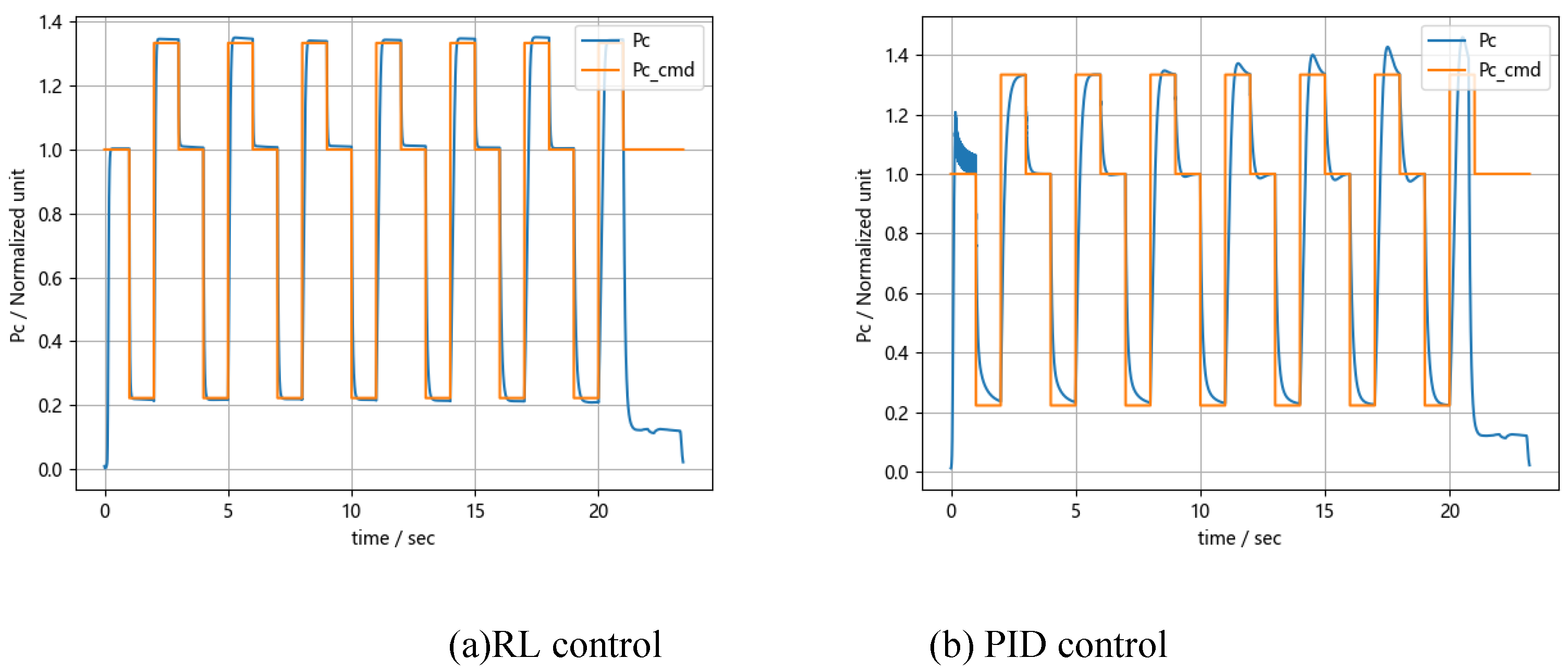
Figure 10.
The control performance by thrust distribution agent.
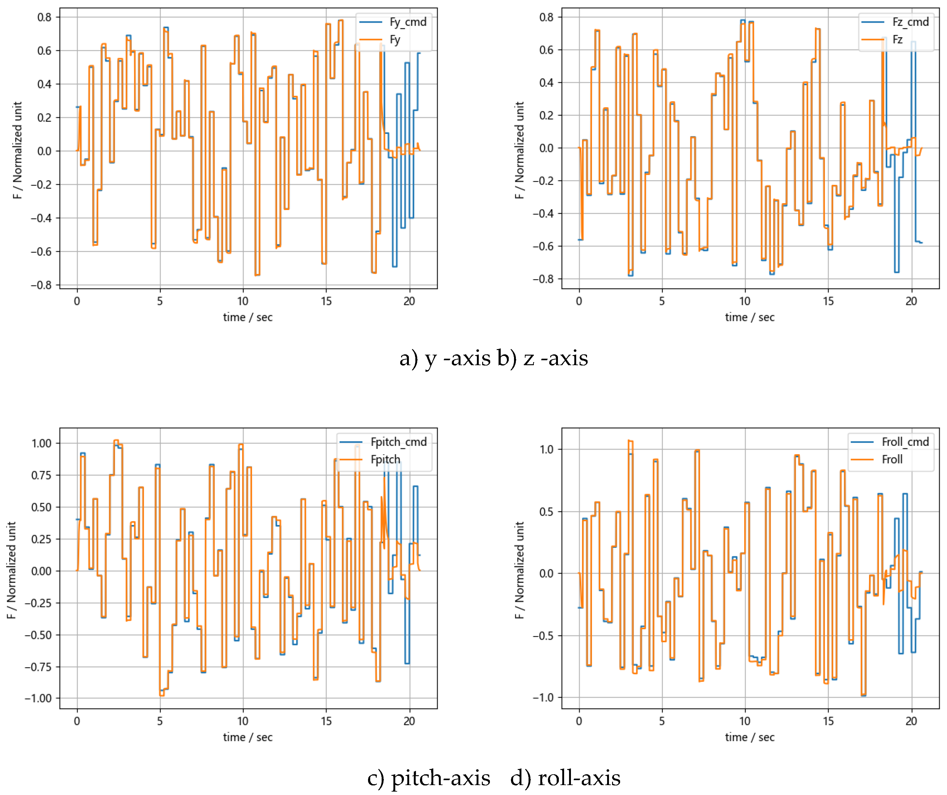
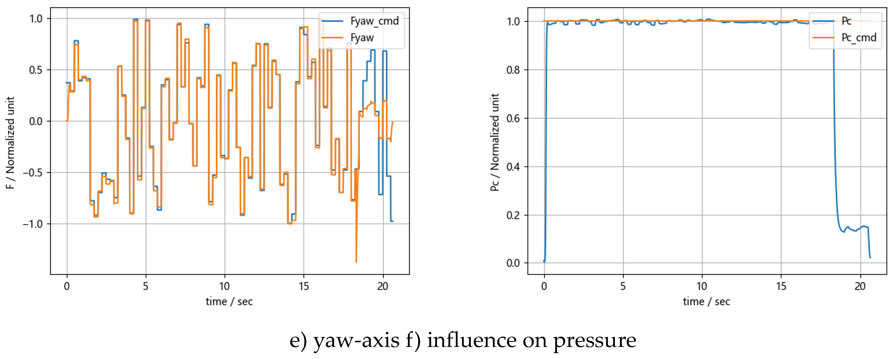
Figure 11.
The control performance by opening closed-loop agent.
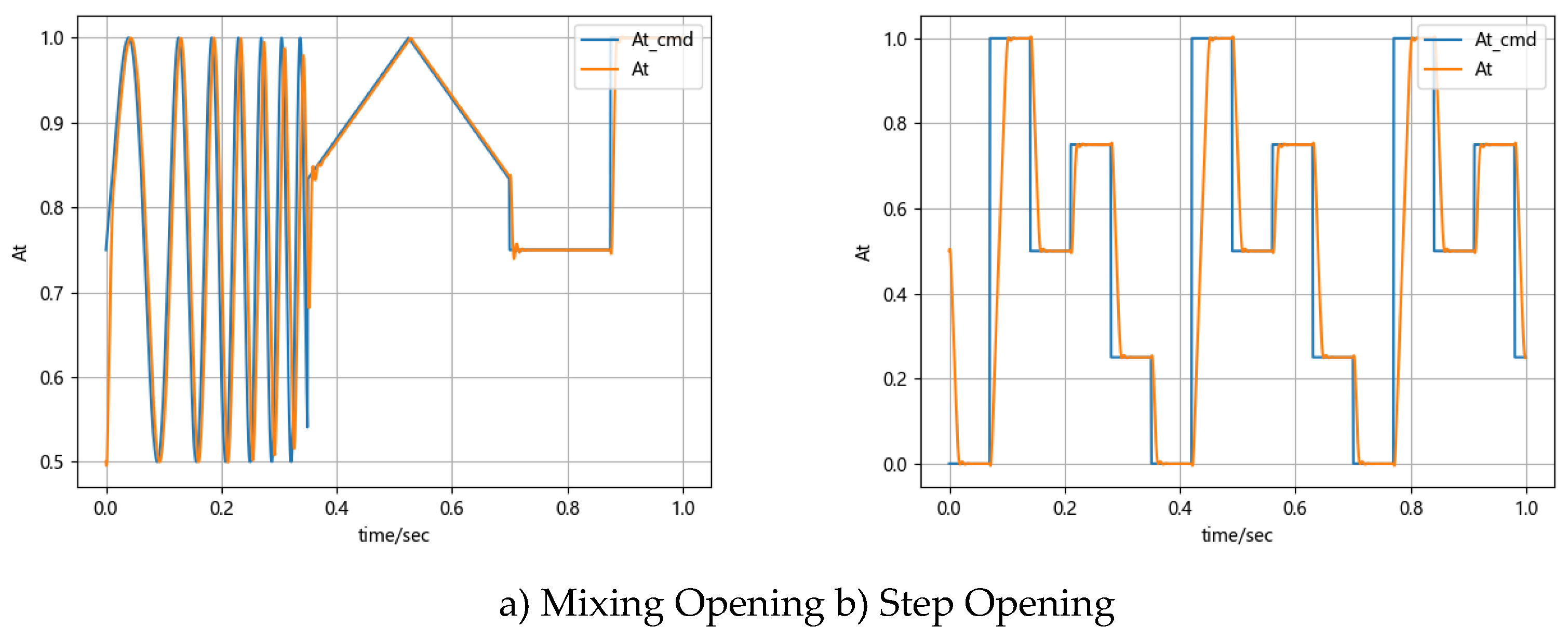
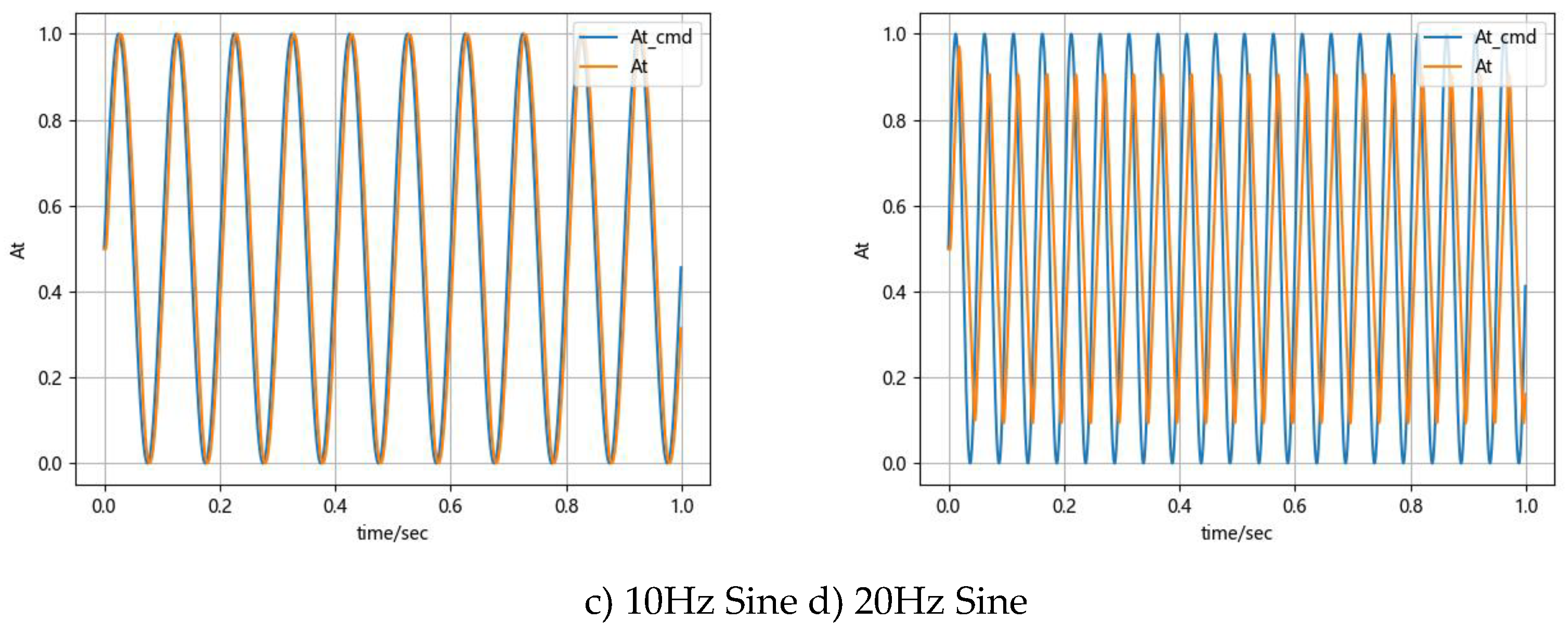
Figure 12.
The performance of the joint agents.
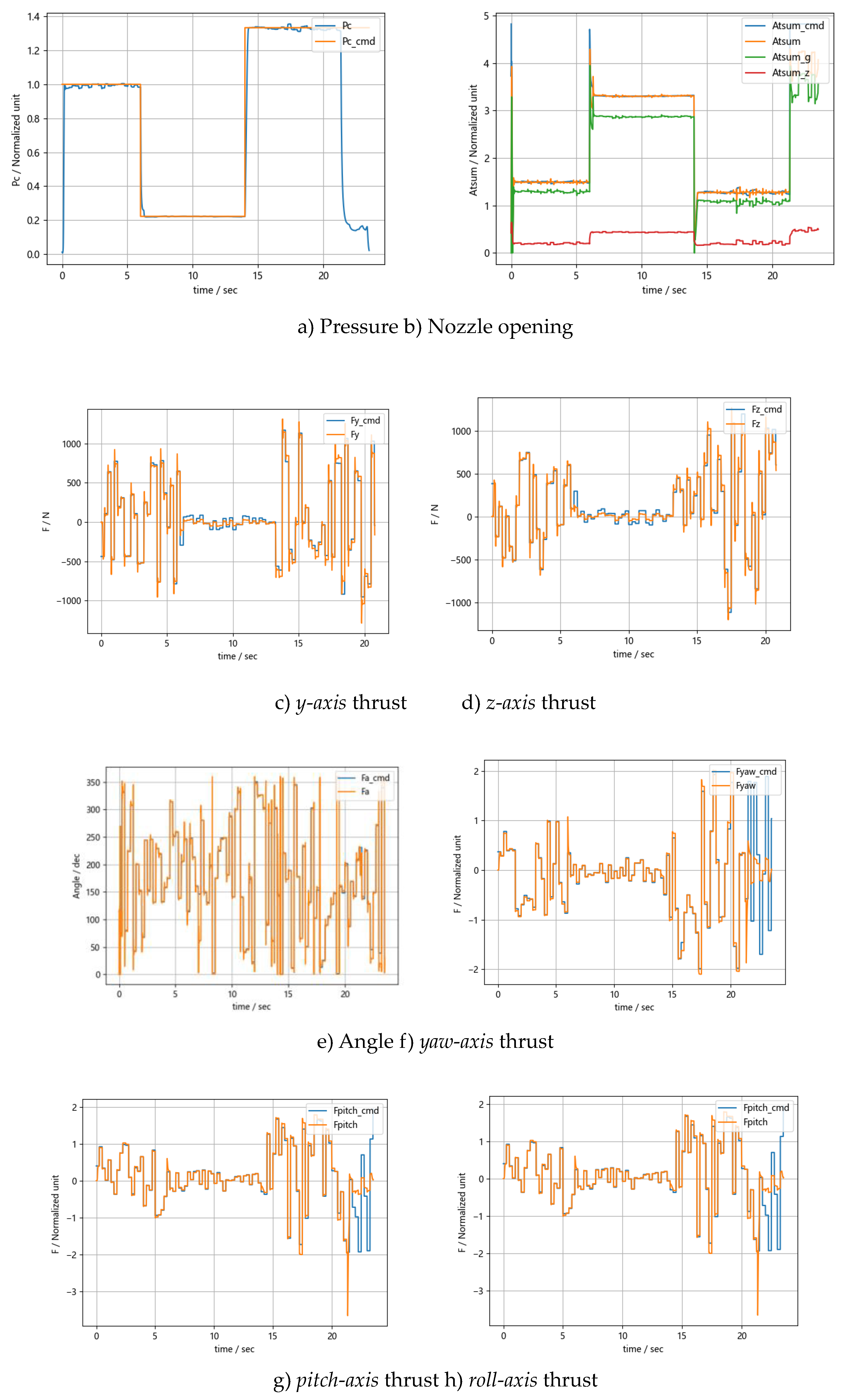

Table 1.
Statistical results of pressure control performance.
| Model | RL-PPO | PID | ||||
|---|---|---|---|---|---|---|
| Item | Cumulative Deviation | Average Deviation | Average Regulation Time, ms | Cumulative Deviation | Average Deviation | Average Regulation Time, ms |
| Value | 304.75 | 0.043 | 244 | 352.50 | 0.051 | 827 |
Table 2.
Statistical results of thrust distribute performance.
| Item | Divert Control Thrust | Attitude Control Thrust | Impact on Pressure |
|---|---|---|---|
| Cumulative Deviation | 252.8 | 732.3 | 30.1 |
| Step Average Deviation | 0.036 | 0.011 | 0.004 |
Table 3.
Control performance for step valve opening commands.
| Command Type | Adjustment Time (t90) /ms |
|---|---|
| 0~1 | 37 |
| 0~0.75 | 29 |
| 0~0.5 | 22 |
| 0~0.25 | 22 |
| 1~0 | 37 |
| 0.75~0 | 29 |
| 0.5~0 | 26 |
| 0.25~0 | 25 |
Table 4.
Control performance for sinusoidal valve opening command.
| Frequency | Amplitude Attenuation | Phase Lag |
|---|---|---|
| 5hz | 0.016-0.992 | 18° |
| 10hz | 0.036-0.936 | 36° |
| 15hz | 0.052-0.968 | 75.6° |
| 20hz | 0.188-0.828 | 144° |
Disclaimer/Publisher’s Note: The statements, opinions and data contained in all publications are solely those of the individual author(s) and contributor(s) and not of MDPI and/or the editor(s). MDPI and/or the editor(s) disclaim responsibility for any injury to people or property resulting from any ideas, methods, instructions or products referred to in the content. |
© 2024 by the authors. Licensee MDPI, Basel, Switzerland. This article is an open access article distributed under the terms and conditions of the Creative Commons Attribution (CC BY) license (http://creativecommons.org/licenses/by/4.0/).
Copyright: This open access article is published under a Creative Commons CC BY 4.0 license, which permit the free download, distribution, and reuse, provided that the author and preprint are cited in any reuse.


