1. Introduction
The yield is necessary for plastic energy absorption, and brittle fracture of the connection prevents the inelastic behavior of the bending connection to withstand seismic loads. Triaxial stresses significantly contribute to a reduction in ductility. When loaded in two or three directions simultaneously, steel does not exhibit its inherent ductility. It will fail brittle fracture without showing an increase in length (Chandrasekaran A. 2023; Miller D.K. 1998). Tremblay et al. (1995) investigated the performance of steel structures during the Northridge and Kobe earthquakes. The brittle fracture and damage caused by connections and the moment-resisting process showed that the design criteria in practice before the 1994 Northridge earthquake did not cause plastic hinges in the beam. In conventional connections after the 1994 Northridge earthquake, the main purpose has been to move plastic hinges into the beam at a certain distance from the column. In such connections, moving plastic hinges away from the face of the column reduces strain concentration in the weld area, weld cracks, and brittle failure in the connection (Faridmehr I. 2019). Several methods have been proposed so far for the transfer of plastic hinges. They can generally be divided into two main categories. In the first category, adding components to the connection increases the beam strength in the connection region. The plastic hinge is transferred into the beam, preventing the connection components from rotating relative to each other (the beam relative to the column). In the second category, reducing resistance in parts of the beam causes a weakening in a specific and predetermined area, which will move the plastic hinge away from the column face. There are different types of Reduced Beam Section (RBS) connections in this category (MoradiGaroosi AR. 2018). Although this design strategy provides a flexible failure mode with high energy dissipation in strong earthquakes, it calls for negative consequences. Extensive plastic deformation and local buckling in the plastic hinge region of steel beam cause permanent deformation and drifting of steel frames. As a result, reconstruction costs increase to the extent that building repairs may become economically unreasonable (Manigandan R. 2023; McCormick J. 2008). Moreover, if not properly detailed, the slab may prevent the fusing behavior of the RBS, in which case the reliability of the RBS connections depends on weld quality with the complete penetration of the beam into the column, causing a brittle connection behavior (Ayough P. 2023; Wilkinson S. 2006). Consequently, the earthquake-resistant design was developed through damage-control techniques to prevent the destruction of structures and recover structural performance after an earthquake (Chen YY 2016; Xilin Lu 2011). The basic principle of this approach is to introduce a weak cross-section to the local structure with energy-dissipating components attached to the main structure, which can be disassembled and installed easily (e.g., the widely-used bolted connection method). When structures respond to severe earthquakes, the flexibility of the replaceable energy-dissipating components increases, leading to large deformations and seismic energy absorption through non-linear behavior. This is done to prevent severe damage to the main structure. Due to seismic loading, repairing structures is limited to replacing the damaged energy-dissipating components, where the total repair costs are significantly reduced (Lu X. 2014).
Attempts have been made to connect the beam to the column using a stub. Yunlu Sh. et al. (2009) conducted an experimental investigation into two types of replaceable connections using the RBS method. This connection is made of a replaceable connection with a smaller cross-section than the main beam to allow for the formation of a plastic hinge. Li et al. (2012) evaluated a specific type of the reverse channel connection as a stub where UNP webs were welded to the box-column and the UNP flange to the beam. SasanMahjoob B. et al. (2020) proposed two novel configurations to connect I-beam to box-column using bolted extended end-plate (BEEP) moment connections. Their configurations comprised a short stub beam (of 100 mm), which was welded to the box-column flange as in the column-tree connection type. Yılmaz et al. (2016) utilized a stub in the form of a short beam to evaluate the finite element method (FEM) of the beam-to-column moment connection in the direction of the weak axis of the column under monotonic loading. Moghadam et al. (2018) developed a unified cross-section with a torsional plate from two parallel connection plates welded vertically to the column. They then connected the beam thereto with a flash end-plate. Gaoxing Hu et al. (2020) developed a replaceable energy dissipation device for connecting beam to precast concrete column using a steel stub composed of a short link made of an open-section H-shaped steel section. Peng H. et al. (2020) developed a beam-column connection to control the seismic damage to steel structures by installing a stub consisting of a mechanical hinge and a pair of buckling-restrained steel plates. Shi Q. et al. (2019) employed a stub with a transfer stiffener, a vertical stiffener, and an end-plate assembly to connect the minor-axis beam of the column. The column-tree connection recently addressed improved connections through improved details, including the no-weld access hole connection and wide-flange stub beam details (Cheng-Chih Ch. 2006), and the horizontal hunch connection (Tanaka N. 2003).
Therefore, the idea of providing a connection with the possibility of it being flexible against structural deformation reduces the damage to beam and column, and the possibility of repairing and replacing the damaged parts. Accordingly, this study used a combination of connections using the stub and end-plate connection to present a somewhat interchangeable connection. Thus, the present study focuses on the connection and the component behavior, leaving other parts, such as the panel zone, the beam, and the column, out of the study focus. Therefore, the model is developed so that it only reflects connection behavior and prevents the non-linear behavior of other components from merging. Consequently, the connection is designed to be weaker than it should so that the beam and column would cause a rupture. For this purpose, used a concrete filled steel box for the column and the beam is reinforced in the area close to the connection to remain elastic during loading.
Connection design criteria are generally based on AISC seismic recommendations. During the experimental program, a sample was made and tested in the laboratory subjected to cyclic loading. Then the calibration and validation of the FEM model was performed based on the experimental results of the sample. Finally, the parameters affecting the behavior of the proposed connections were determined via modeling in the FEM software, and the design method was presented.
2. Proposed Connection
2.1. Configuration
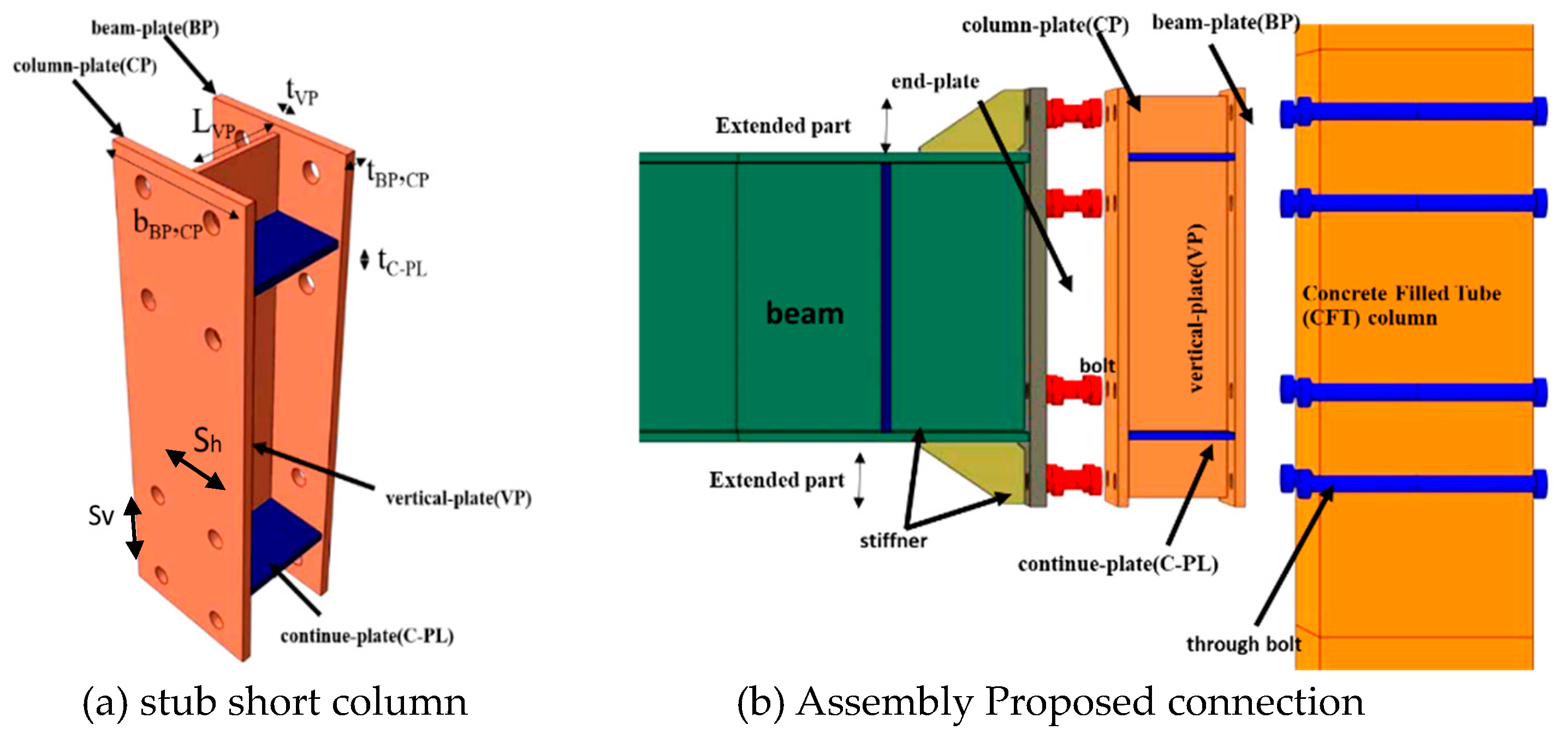
In general, the proposed connection is connected to the box-column by installing an H- or I-shaped section as a short stub column (SSC) with a through-bolt as shown in
Figure 1. Also, mechanical specifications of the plates used in the construction are given in
Table 1. The SSC connection consists of two parts. The first part includes an end-plate (EP) welded to the end of the beam. A triangular stiffener plate is welded between the end-plate and beam flanges to strengthen the expanded part. This stiffener reduces the prying action and distributes the tensile and compressive forces of the flange between the bolts (Morrison M. 2017). The second part of the SSC connection includes a stub consisting of a beam-plate (BP) and a column-plate (CP) (generally a flange stub) that are spaced apart. The two plates are parallel to the column flanges. They are then welded together with a vertical-plate (VP) (generally a web stub) along the beam axis with four continuity plates (C-PL) in the direction of the beam flanges on either side of the vertical-plate. They are welded to form a unified stub. This stub is located between the end-plate and the column. The BP is connected to the end-plate and the CP to the flange column with bolts. This connection is designed so that the beam, column, and end-plate exhibit elastic behaviour when loading, where the stub enters the plastic behaviour step and causes energy loss. After loading, it can be replaced or repaired if necessary. In the proposed SSC connection, additional flexibility is created in the connection behaviour with two parallel bolted plates. The height of the stub and the end-plate is higher than the beam, which is reinforced between two stub flanges with continuity plates. The ductility and rigidity of the connection can be controlled by determining the situation and number of continuity plates. Since the welds are performed before the assembly of the structure, there is a possibility of higher-quality, more economical, and easier inspection of the connection.
In conventional moment connections, the moment is transferred from the beam to the column as a force coupling, resulting in two concentrated forces in the connection region on the column. This increases stress in the panel zone. Therefore, using the extended stub in connections increases the contact surface and distribution forces on the column, which reduces the stress on the panel zone in addition to ductility.
The main function of the stub is to act as a damper with non-linear behaviour, preventing the transfer of excess moment from the beam to the column. Since the stub, especially the thickness of BP, CP, VP, and C-PL, significantly affects the connection behaviour, the performance of the structure can be controlled by properly designing the thickness of the parts in the proposed connection. In other words, the optimal cross-section for the connection can be designed by determining the maximum moment transfer from the beam to the column by the stub. Better seismic performance is achieved by increasing the flexibility of structures to reduce the number of plastic hinges (Moghaddam HA 1999). It also maintains maximum transfer moment from the beam to the column, and the structural performance levels can increase according to ASCE41-06 (Committee 2007). Using the SSC connection in an acceptable drift ratio, the stiffness limit of the beam-to-column connection is effectively reduced due to flexibility. Moreover, the fracture energy capacity increases for this type of connection (Wang M. 2013).
2.2. Connection Force Transfer Mechanism
In the stub web (VP), a panel zone similar to the column is formed, reducing stress at the column panel zone. In the BP, CP connection area bolted to the column and the end-plate, the prying action causes bending between the two bolts. The C-PL stiffener redistributes our strain between flanges (BP, CP) and the web (VP) of the stub. It contributes to the load-bearing capacity of all parts of the stub. Expanded parts outside the beam height in the stub act as a stiffener and transfer significant force to the outer bolts. Increased displacement at the top of the column causes large deformation and plastic strain of the expanded part outside the beam height on the one side and buckling on the opposite side. It also causes more C-PL participation in the transmission and creates the prying action of the bolts in BP, CP. Then, increased displacement causes the expanded parts of the stub to fracture. The tensile and compressive forces are transferred from BP to CP by the C-PL stiffener. Eventually, with the intensification of the prying action of the bolts, the CP will fracture in part between the bolts.
3. Experimental Program
3.1. Experimental Configuration
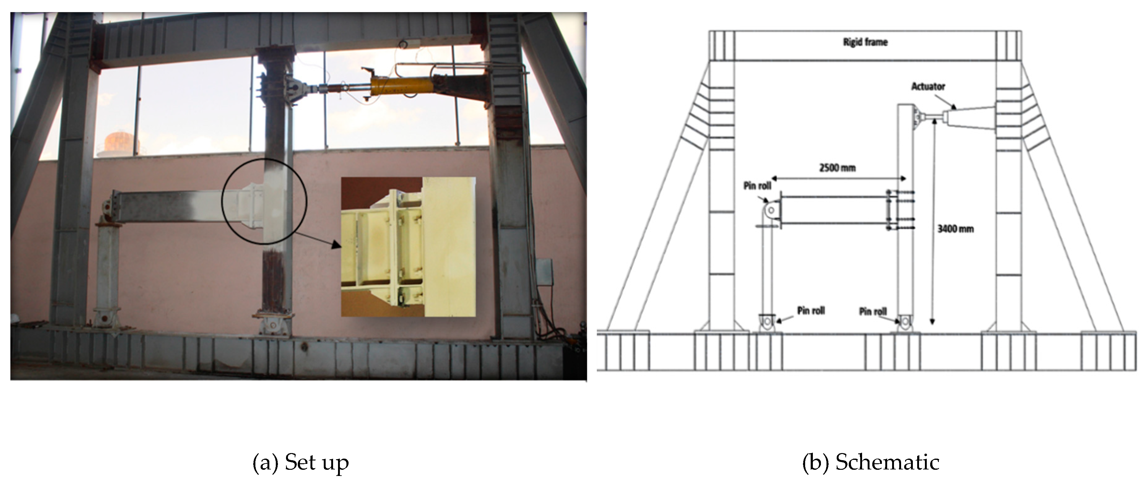
The internal test specimen was assumed to be a rigid bending frame. The experimental configuration is illustrated in
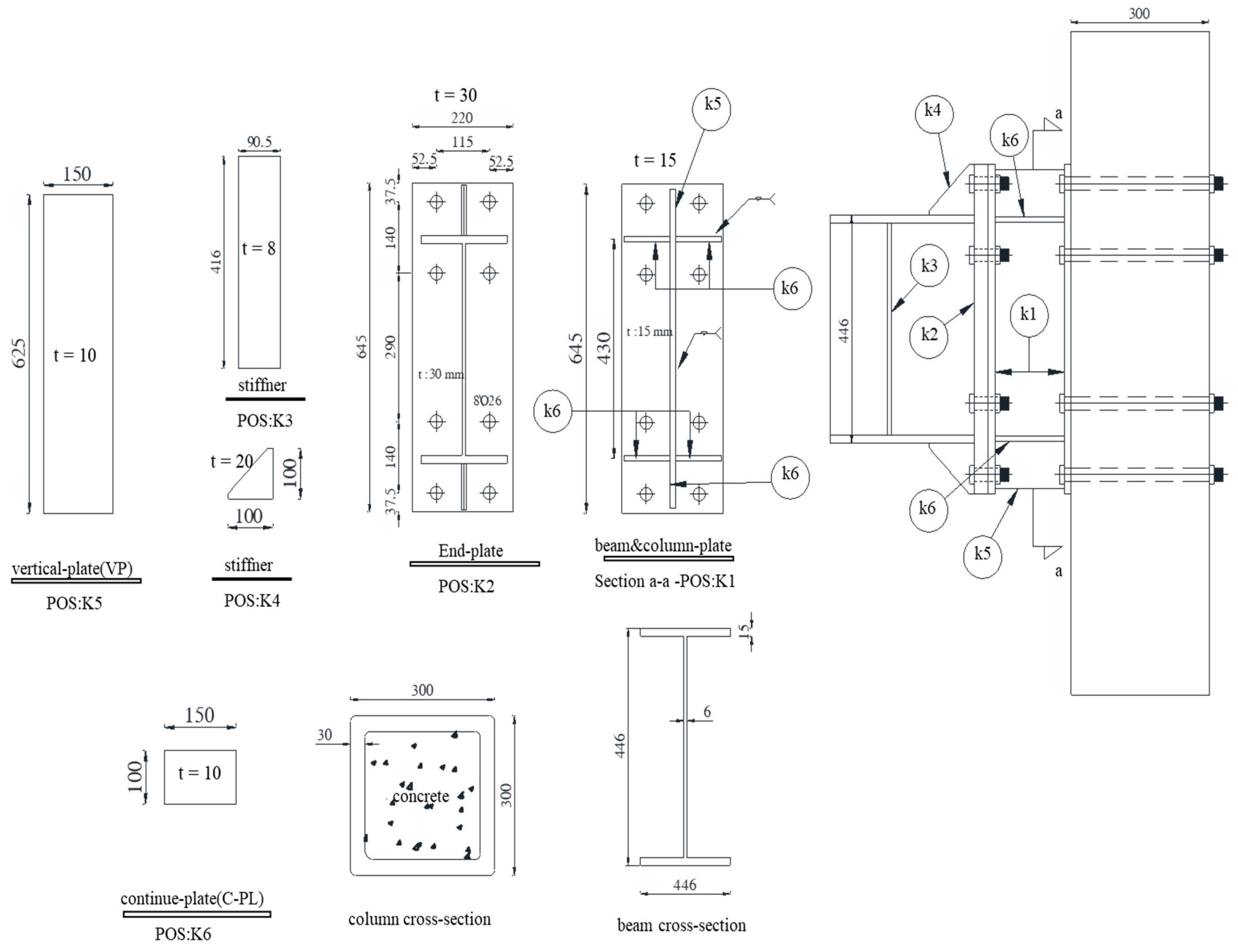
Figure 2. The column was located on a pinned support while the load was applied to the top of the column. At the top of the column, a roller system was installed to create lateral support and prevent movement outside the column plate. The hydraulic actuator was fixed in a rigid frame and attached to the column. At the end of the beam, the roller bearing conditions were connected with a link using two connections: one attached to the end of the beam and the other on the rigid frame. Cyclic displacement was applied at the top of the column. The hydraulic loading system, installed between the frame support and the top of the column, consisted of a 300KN hydraulic actuator with a maximum cycle of 600 mm. The column was a Concrete Filled Steel Box with 300mm width and 30mm thickness. The concrete used in the steel-fiber-reinforced-concrete (SFRC) column was of the compressive strength of 35.4 MPa (Saffarian I 2023b). The beam was of a plate girder type with a height of 446 mm and a flange width of 187 mm. The column (from support to the point where the load was applied) and the beam (from the center of the column line to the support) were considered to be 3400 and 2500 mm, respectively. The column with an almost "rigid" behaviour was used in the test sample. The end-plate was welded to the beam flange by a 20 mm-thick triangular stiffener. The beam web and flange were reinforced on both sides of the beam web, 200 mm from the end-plate, with two 8mm-thick rectangular stiffeners. The box-column was constructed of st52 steel, an end-plate, and a beam, while other connecting plates were constructed of st37 steel. The standard coupon test was extracted from the plates used to construct the test specimens. The properties of the materials obtained from the tensile test are shown in
Table 1. White paint was sprayed on samples to show the inelastic deformation of connection components during the test. CO2 welding was used for all welds. A welding resistance of 4500 kg/cm2 (Charpy V-notch toughness (CVN) of 50 J at -20°C) was calculated for electrodes 1.2 mm in diameter. The design of the sections was based on previous research. The necessary controls such as seismic compression of beam and column sections, strong column-weak beam theory was also applied. Geometric details of connection components and section dimensions can be seen in
Figure 3. The bolts utilized in the test correspond to the high-strength bolts 10.9 degrees M26. Finally, the mechanical properties of the bolts were as follows: fy = 994 MPa, fu = 1202 MPa, and elongation = 15.2%.
3.2. Loading History
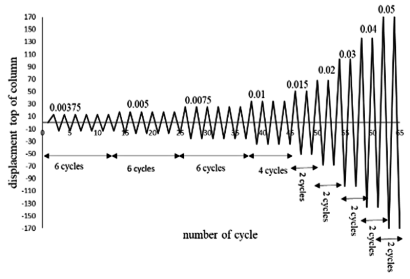
In the first step, the pre-tension force of the bolt was applied before loading the sample. For high-strength bolts, the tensile force was controlled with a torque meter. According to AISC regulations, the force created should be sufficient to create a tension equal to 70% of maximum bolt capacity. In the second step, loading was a displacement control. The loading history was selected in the experimental sample proposed with AISC 341-16 ((AISC) 2016) and the SAC/BD-97/02 (Clark P. 2018) loading protocol, as shown in
Figure 4. This protocol is based on the relative rotation of the top of the column. The sample is loaded by a quasi-static and displacement control form. Moreover, loading occurred at a low speed.
3.3. Experimental Results
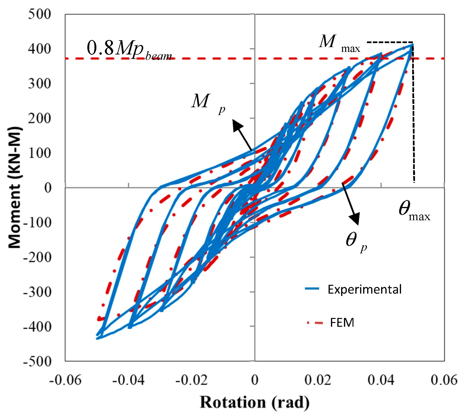
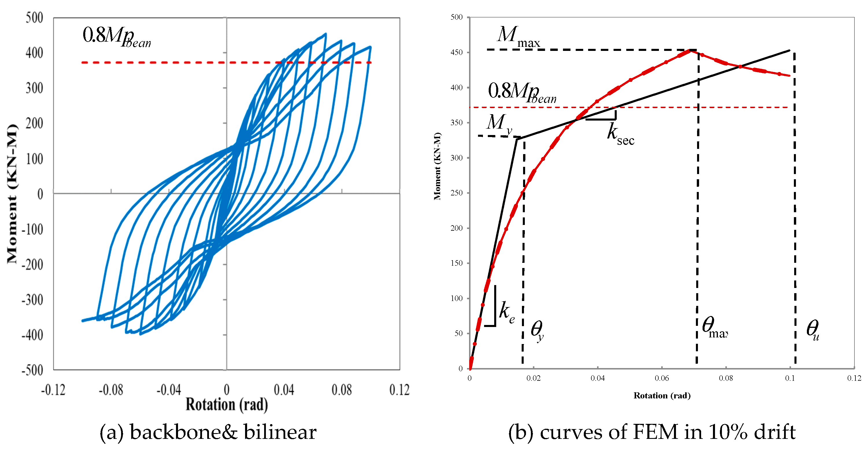
Cyclic loading continued up to a drift angle of 0.05 rad for the test sample. Moreover, the moment-rotation curve of the sample was obtained, as shown in
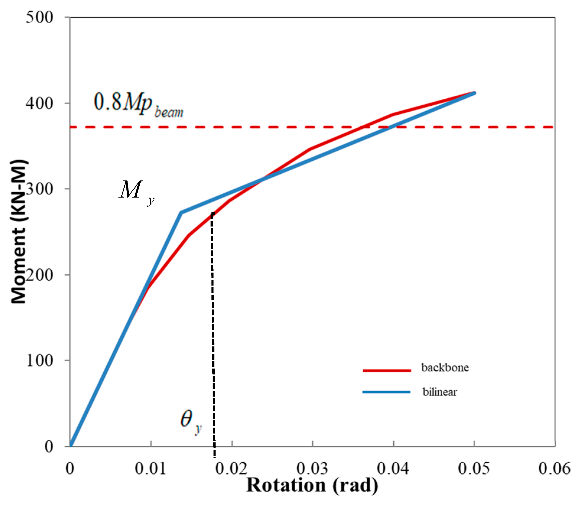
Figure 5. A backbone curve for experimental and FEA models was plotted for the positive region of the moment-rotation curve and an equivalent bilinear curve according to FEMA-440 criteria (440 2005) in
Figure 6. The sample provided the requirements of the AISC ((AISC) 2016) with respect to the special moment frame (SMF). The moment was equivalent to multiplying the shear load at the top of the column by the distance from where the load was applied to the column support. The drift angle between the sections was equal to the column tip displacement divided by the distance from the load application place to the column support. The results are summarized in
Table 2.
3.4. General Test Observations
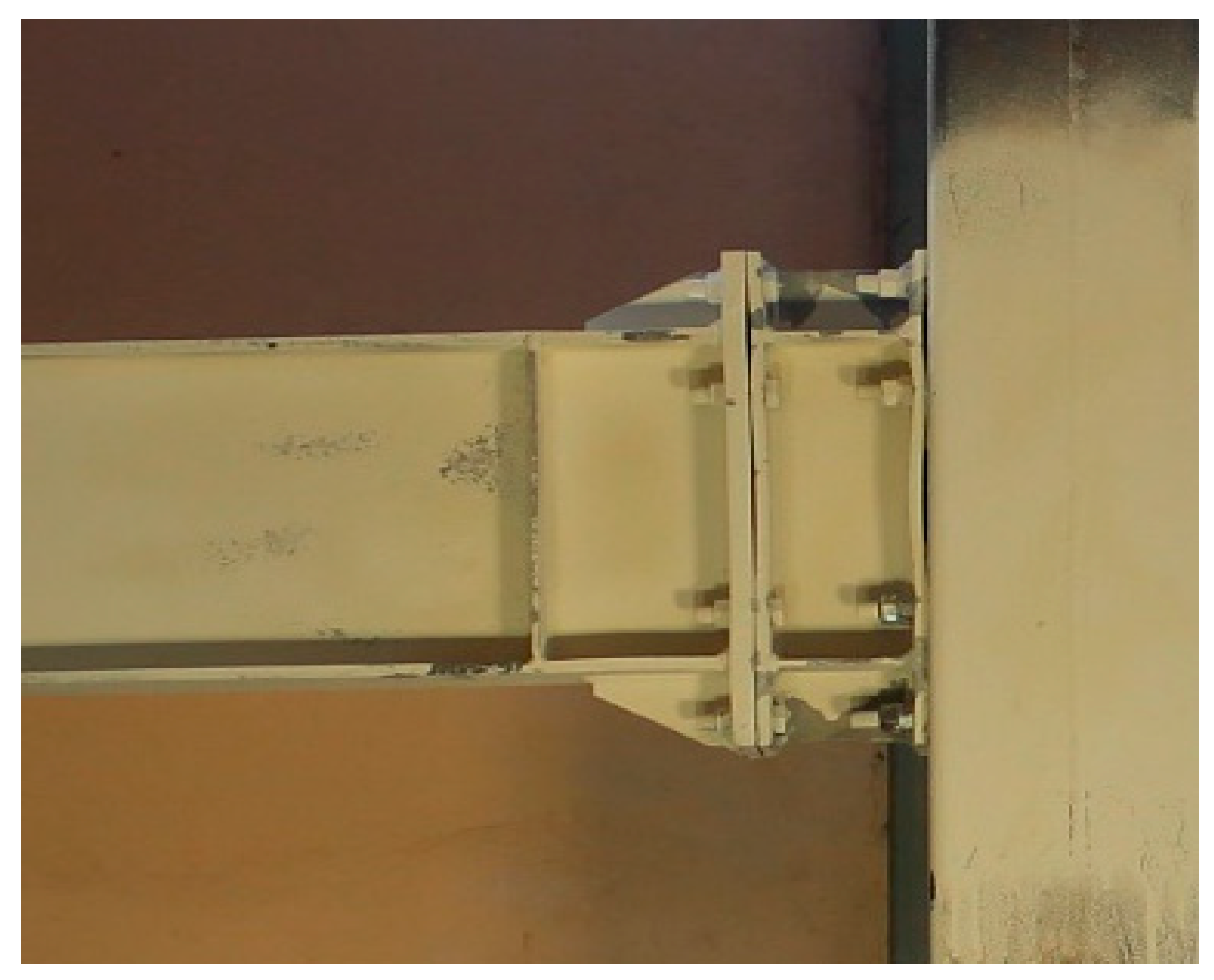
The first yield in the VP started in the extended part during the first cycle of the 1% drift. With increasing drift, local buckling occurred in the compressive part of the 2% drift. This caused more C-PL participation in bearing forces. In the drift, 4% of the white paint sprayed in this part became scaly. In other parts of the stub, the strains were slightly less yielding. The stub (BP, CP) flanges between the two rows of bolts exhibit behaviour similar to T-stub connections. The prying action of the bolts increased periodically, causing the BP and CP to bend, which will be effective in the stub due to the high end-plate strength of the prying action. As demonstrated in
Figure 7, the nonlinear behavior of the test specimen was due to local yield and buckling during cyclic loading. No failure was seen in the stub until 5% drift. Hysteresis loops are stable samples that show good flexibility and energy dissipation. There was a pinching effect on the moment-rotation curve under cyclic loading.
4. Numerical Investigation of the Proposed Model
4.1. Finite Element Modeling
In this section first analyzed the experimental sample using the non-linear finite element method. The accuracy of the results was then investigated. Based on the properties of the materials obtained through tensile testing (
Table 1), a numerical model of an experimental sample was built in ABAQUS. The materials, support conditions, and dimensions of sections were also similar to the experimental sample. All members were modeled as solid parts with deformable capability. For the stub part, since the weld root reduced the buckling length of the VP, C-PL, it was essential to model the weld as a triangular part. However, for other parts, such as connecting the beam to the end-plate and stiffeners to the beam, the welds were not explicitly modeled in the element simulation due to the high strength of the welding materials compared to ordinary steel. The constraint property of the tie type was used. This constraint allows two regions with different meshes to be combined. The stress-strain curve in three lines was ideal for introducing its hardening behavior. The criterion of the plasticity of materials was considered based on Von Mises's critical, isotropic, and kinematic hardness in the non-linear behaviour of materials. The software plasticity settings set the hardening mode to combined and stabilized, where it is also possible to model cyclic hardening. The Young's modulus of elasticity and the Poisson's ratio were 2.05 × 10⁵ MPa and 0.3, respectively. Since the loading was performed in the experimental model at low speed, the analysis type was static and general. This type of analysis can solve and simulate lateral buckling and cyclic loadings. Two steps of analysis were considered. In the first step, the pre-tensioning force of the bolts was applied. In the second step, according to the experimental sample, lateral cyclic loading was applied at the top of the column. Loading was done according to
Section 3.2. It is important to note that only one loading cycle was performed for each drift level due to a reduction in FEM calculations.
One of the complicated steps in simulating bolted connections was introducing contact elements. The model had 167 interactions. The contact element consisted of two main parameters. The first parameter of normal behavior caused hard contact and prevented the two surfaces from penetrating each other. The second parameter of tangential behavior was the friction between surfaces. This factor was considered equal to 0.3. The contact between the bolt body and holes was defined as the small sliding parameter. This parameter caused bolts and plates to slide along each other. The finite sliding parameter was activated to prevent them from slipping and loosening in contact with the nut and bolt. In all contacts options, the specified tolerance parameter for the adjustment zone was activated, and the value of 0.05 was entered as a coefficient. This option would help converge the analysis.
The finer the mesh density, the closer the results would be to reality, and the longer the analysis time. Therefore, its amount must be optimized. For this purpose, the fine mesh was only used near the stub. Finally, 55,683 elements and 163,561 nodes were considered for the final model. In this study, two types of elements were used: the C3D8R element with eight linear types and the C3D20R elements (Saffarian I 2023a) with twenty nodes of the quadratic type. Beam and bolts of twenty nodes and other members were modeled with eight nodes. Both elements could have plasticity, hardness, large deformations, and non-linear behavior, and each node had three degrees of freedom. The number of Gauss integration points was also reduced.
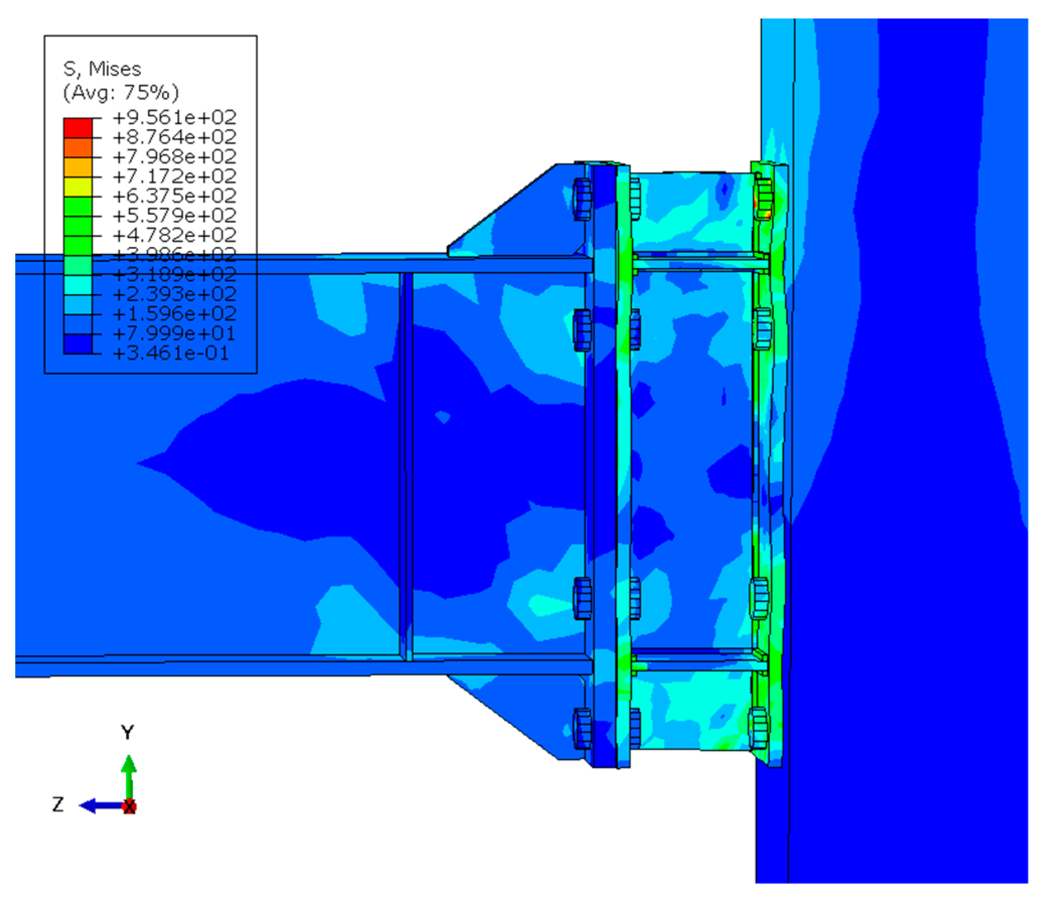
The modeling result and the accuracy of the extracted results are compared with the experimental sample results. A Moment-rotation hysteresis curve is plotted and compared with the experimental sample in
Figure 5. The parameters affecting validation, including maximum moment, yield moment, plastic moment, maximum drift, yield drift, and plastic drift, are presented in
Figure 5. The results are summarized in
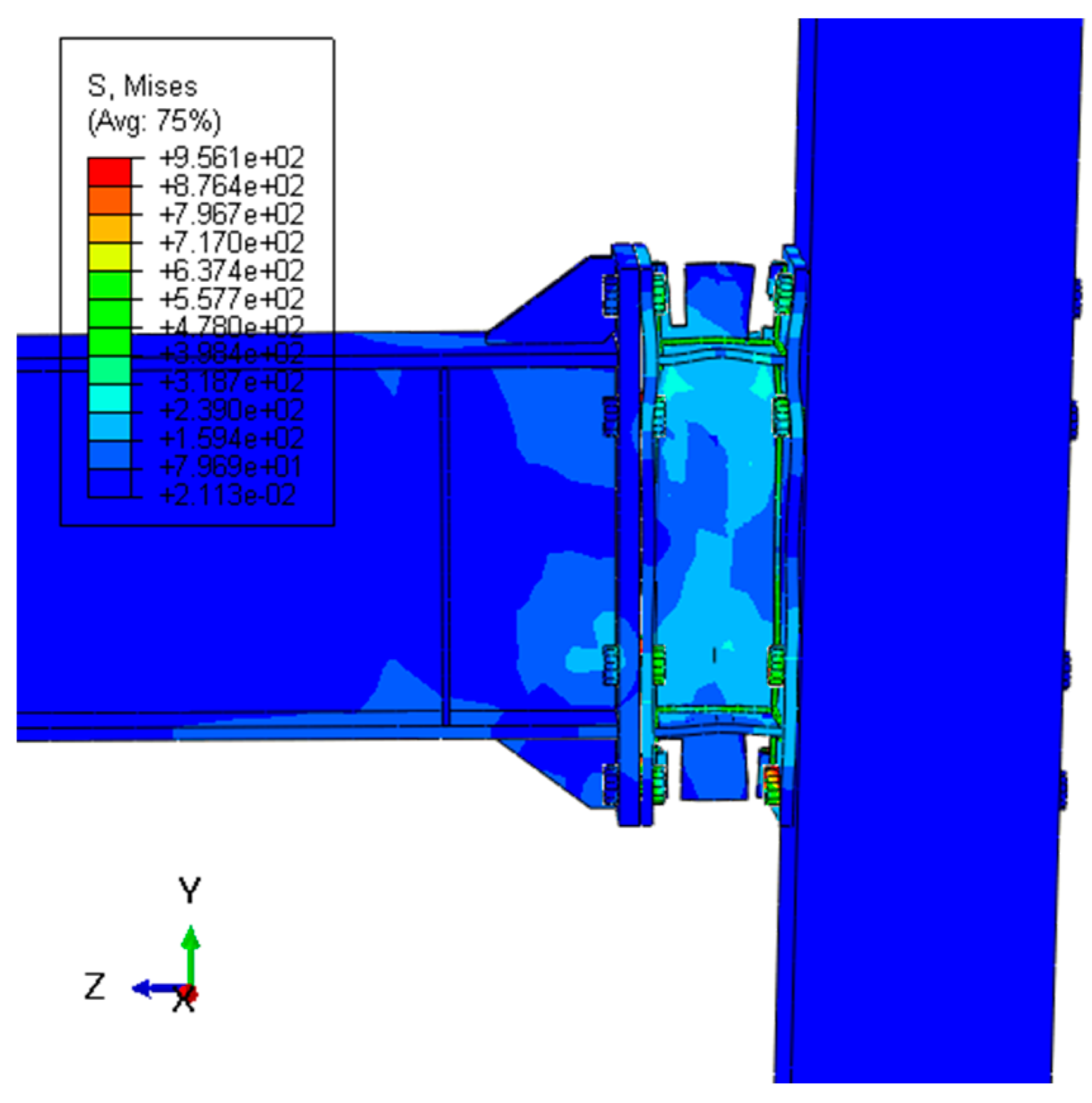
Table 2. As can be seen, the FEA results have reasonable proximity and a low error rate compared to experimental results. One of the most important reasons for the accuracy of modeling was the deformation mode and its compatibility with the experimental model shown in
Figure 8.
4.2. Analysis and Discussion
The FEA was continued until evaluated the behaviour and determined the fracture mode of the proposed connection. As shown in
Figure 9 the moment-rotation curve continued up to the displacement at the top of the column in a positive direction, up to 7% drift, without any reduction in resistance. However, in the displacement at the top of the column in a negative direction and the moment-rotation curve in the -7% drift, the resistance decreased due to the VP fracture in the extended stub connection. As the load continued, the VP broke from the top and bottom of the stub to the C-PL edge. Then, with further participation of the C-PL in the bearing forces, the fracture stopped, and a connection with the new geometry was formed (
Figure 10). The new geometry of the connection maintained its stability. However, as depicted in the moment-rotation curve, there was a slight decrease in resistance (in the 8% drift), about 4%, compared to the maximum moment. With continued loading, the connection had more ductility and less force tolerance than its previous state. The FEA continued until drift was 10%. As the prying action increased during this drift, a plastic hinge was formed between the bolts in the CP, and the analysis was aborted. However, the connection did not generally break and maintained its stability.
5. Parametric Study of the Proposed Connection
The parametric study was performed to investigate the effects of changing geometric dimensions on the behavior of the proposed connection. This study was conducted basically on the calibration of the FEA model in
Section 4. For this purpose, the geometric dimensions of the experimental model of
Section 3 were considered as the base model, where only the geometric details of the stub part were changed. Other parts, including end-plate beam, bolt arrangement, bolt diameter, and stiffeners, were fixed. Changes included those in stub flange thickness (tBP, tCP), stub web thickness (tVP), continuity plate of stub thickness (tC-PL), stub web length (LVP), and stub flange width (bBP, CP). The details and specifications of the samples are shown in
Figure 1a and
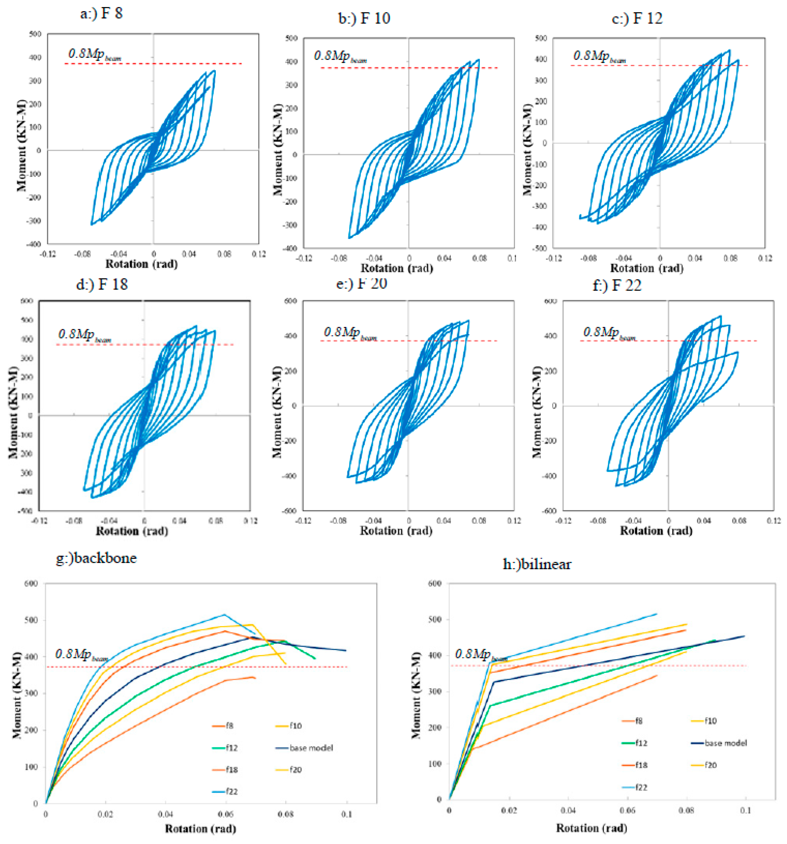
Table 3. All the samples were subjected to cyclic loading, and their moment-rotation and backbone & bilinear curves has been plotted. The curves are shown in
Figure 11,
Figure 12,
Figure 13,
Figure 14 and
Figure 15, and the results were summarized in
Table 4. The parameters of yield moment My, yield drift θy, maximum moment M
max, maximum drift θ
max (corresponding to M
max) were then obtained. Due to the stability of the proposed connection system after dropping the moment-rotation curve, to draw a bilinear diagram, the descending part of the backbone diagram up to a drop of 0.8Mmax was considered final θu drift in calculating parameters. The parameters of, maximum ductility μmax, and final ductility μu were also calculated.
According to the AISC 341-16 requirements ((AISC) 2016), beam-to-column connections used in special seismic-force-resisting systems need to be capable of accommodating a story drift angle of at least 0.04 rad. The connection's measured flexural resistance should be equivalent to at least 0.8MP of the connected beam at this story drift angle. MP is the possible plastic hinge moment.
Ry is multiplied to account for the difference between the minimum specified yield strength (Fy) and the expected yield strengths. Additionally, Zb is the beam plastic modulus at the plastic hinge region. The multiplier 1.1 corresponds to the peak connection strength, including limited strain hardening and other types of over strength. To compare the studied models with this criterion, the amounts of 0.8Mp are specified by a line in the moment-rotation hysteresis diagrams.
5.1. General Analysis and Discussion of Proposed Connection
In the proposed connection, a panel zone similar to that of the column is formed in the stub web. This led to the improved ductility of the connection and reduced stress in the column panel zone. The bolted connection of the stub flange with the column, the bolt pry action, creates a plastic hinge between the two rows of bolts. However, this force is considerably lower than that created in conventional bolted connections due to the stiffener in front of it, which shares the applied force among all the connection parts by redistributing the strain between the stub flange and the web. The parts extended beyond the beam's height in the connection act as a stiffener and transfer considerable moment to the outer bolts. The stub web presence causes more stress transfer over a larger surface of the stub flange bolted to the column flange. Subsequently, a larger area of the column is subjected to compressive stress. Therefore, the stress in the column panel zone decreases. The use of Variable components thickness in the stub makes it possible for the behavior to mode from semi-rigid to rigid. That is means determinable that the connection behavior by changing the components thickness. The Results (
Table 4) illustrated that the M0.04rad/0.8MPbeam ratio can be variable. If the components thickness is greater than the thickness of the base model, this ratio is great than 1. Therefore, the stub satisfies all the requirements for a rigid connection between beam and column, according to AISC and these samples are accepted for special moment-resisting frames. If the components thickness is lesser than the thickness of the base model, the M0.04rad/0.8MPbeam ratio is less than 1.in this case the proposed connection having a fuse-like behavior and the plastic hinge to be formed in the stub section.
5.2. Flange Stub Thickness Variation Effect (tBP, CP)
In this study, the thicknesses of BP and CP were considered equal, and the FEA was performed for thicknesses of 8, 10, 12, 18, 20, and 22 mm. Among the samples, the thickness change of tBP, CP, in the base model, had the maximum elastic drift θy. With an increase in the thickness of the BP and CP, their behavior moved from the thin plate to the thick plate behavior, as observed in the behavior of the end-plate connection (Morrison M. 2017). As the thickness of the BP and CP increased up to 15 mm, the elastic drift θy and the final drift θu increased, and then slightly decreased.
Model f12 with 8% drift had the maximum drift value θmax. The maximum values of My, Mmax, are related to Model f22. The maximum and minimum values of μmax and μu are related to Models f8 and f22, respectively. The results show that increasing the BP and CP thickness improves the strength and reduces the ductility of the SSC connections. The fracture of Models f8 and f10 was due to the plastic hinge formation and the fracture between two rows of bolts in the BP and CP. With increasing thickness in Model f12 and the base model, the fracture will start in the extended part of the VP plate. The analysis failed due to the tension by forming a plastic hinge between two rows of bolts in the BP and CP. In Models f18, f20, and f22, the fracture started in the extended part of the VP plate and stopped when it reached the C-PL plates. With continuing loading, the analysis was aborted by buckling the VP and C-PL in the compression part of the stub and tension in the opposite part.
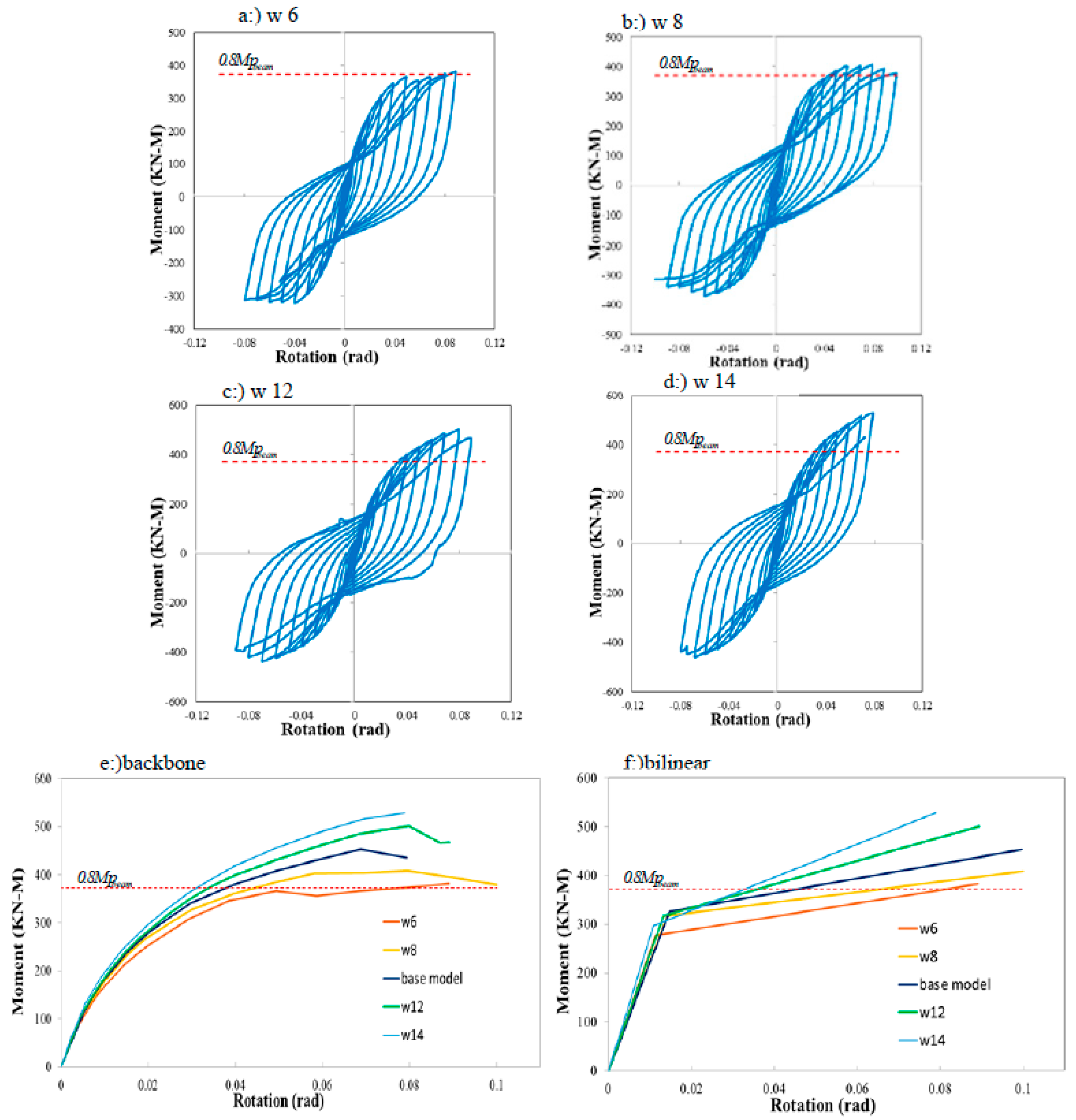
5.3. Web Stub Thickness Variation Effect (tVP)
The main function of the VP plate was to withstand the shear force. In the SSC connection, the VP plate consisted of two parts. The first part was located in the extended section. Since it was higher than the surface of the beam flange and created a prying action, it created much strength against the tensile and compressive forces caused by the bending moment. The thickness of the VP plate, in this part, would have the most significant impact on the maximum moment. The second part of the VP plate was placed between two C-PL plates, which withstand the shear force. The VP plate was also employed as a stiffener for the C-PL, BP, and CP plates and reduced the buckling length of the C-PL plate. In this study, FEA analysis was performed for VP for thicknesses of 6,8,12,14 mm. Based on the results, the base model with tVP = 10 mm had the maximum value of θy, i.e., 1.5%. Models w8, w12, and w14, with 8% drift, had the maximum value θmax, and Model w8, with 10% drift, had the maximum value θu. The base model also had the maximum value of My. Model w14 had the maximum value of Mmax and μmax. The fracture mode of all models of this section was the same and began with the VP fracture in the tensile part and buckling of the VP in the compression part. The analysis was then aborted by the C-PL tension and formation of a plastic hinge between the bolts of the BP and CP.
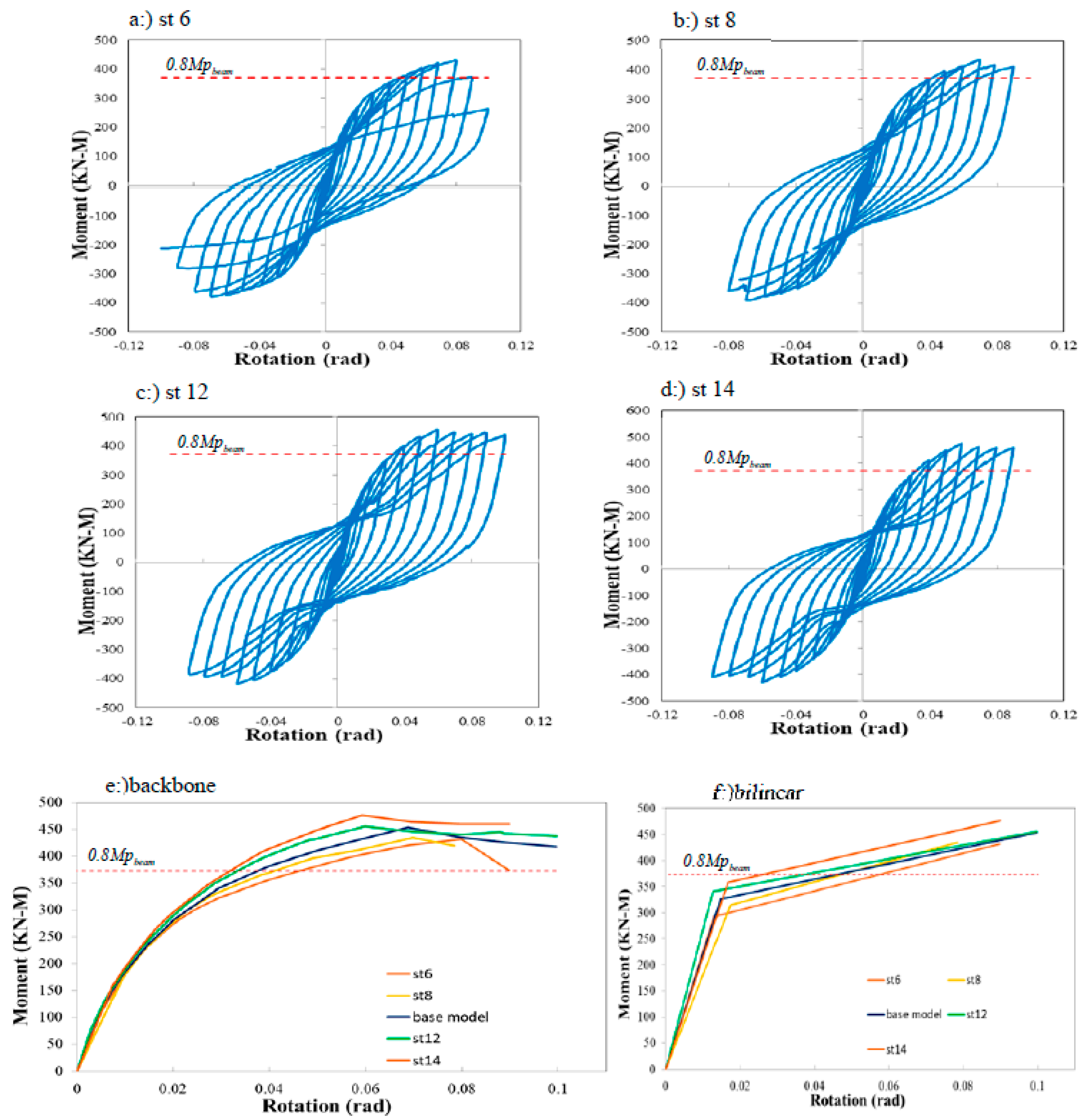
5.4. Continuity Plate Stub Thickness Variation Effect (tC-PL)
The C-PL plates were considered a continuity plate for the stub. They were responsible for transmitting the tensile and compressive forces caused by the bending moment of the beam. The FEA was performed for the C-PL plates for thicknesses of 6,8,12 and 14 mm. As can be seen, Model st8 had the maximum value of θy equal to 1.5%, and Model st6 with 8% had the maximum value of θmax and μmax equal to 6.2%. Model st12 had the maximum value of θu equal to 10% and μu equal to 7.8. Model st14 had the maximum value of My equal to 358 KN-M and Mmax equal to 476 KN-M. Model st6 failed due to the C-PL fracture, but the stress of the C-PL did not reach the ultimate stress in other models. It only experienced buckling in the compression part.
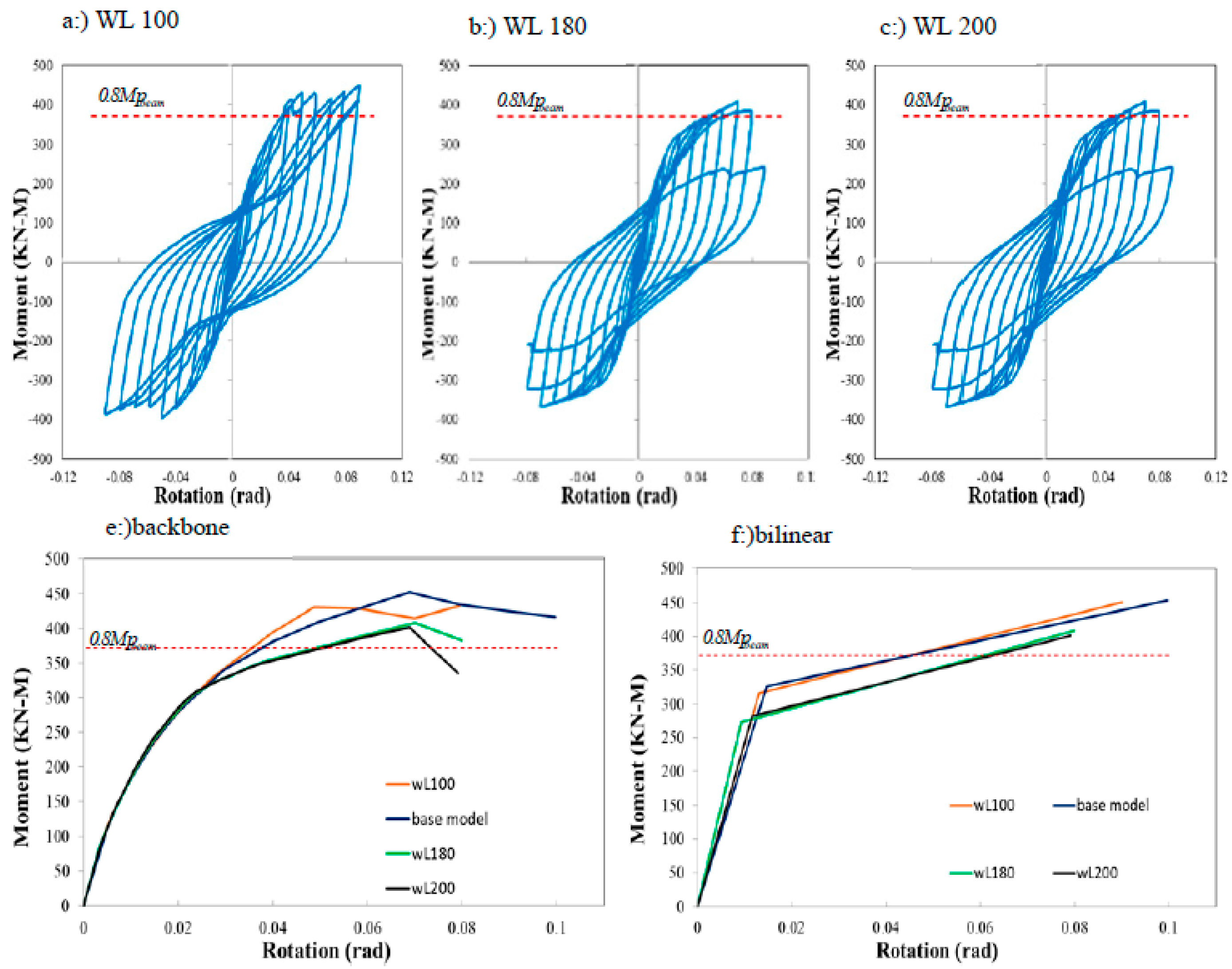
5.5. Long Web Stub Variation Effect (LVP)
The distance between the two plates BP and BC (stub depth), can change the strength and ductility of the connection. The greater the stub depth, the greater the ratio of width to thickness (b/t) of the VP and C-PL plates, and consequently, the connection strength decreases. The FEA was performed for a stub depth of 100,180,200 mm. Increasing the stub depth up to 150 mm (the base model) increases the connection parameters such as My, Mmax, θy, θmax, θu. However, increasing the stub depth by more than 150 mm reduced these parameters. Additionally, the values of μmax and μu increased to a stub depth of 180 mm (Model WL180).
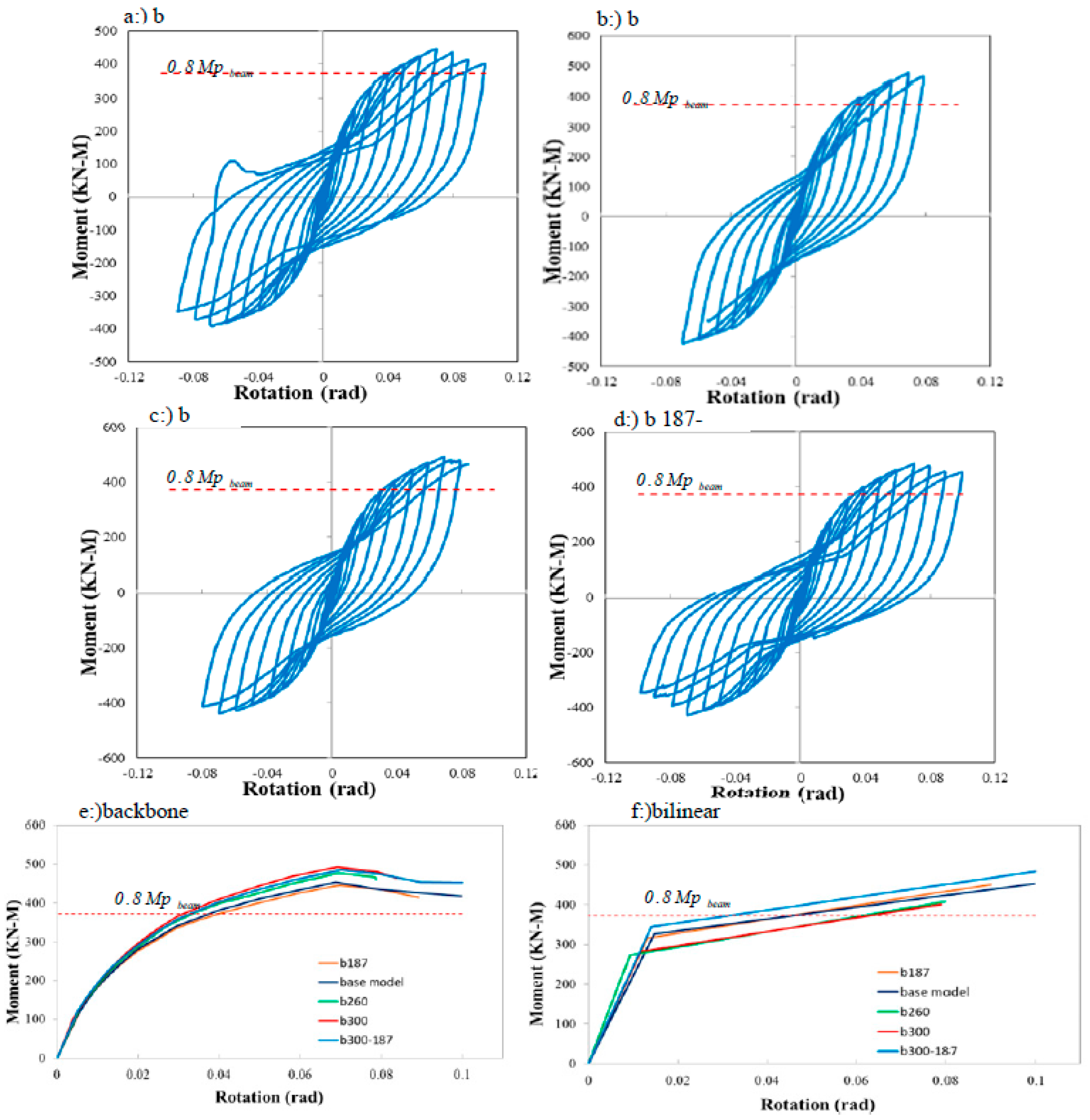
5.6. Width Flange Stub Variation Effect (bBP, CP)
The width of the CP and BP plates was determined based on executive considerations, such as beam flange width, column flange width, and bolt spacing. The FEA was performed for the CP and BP plates with widths equal to bBP, CP = 187 mm (equal to beam flange width) and bBP, CP = 260 mm and bBP width, bCP = 300 mm (equal to column flange width). A model with variable width (the BP plate width equal to 187 mm and the CP plate width equal to 300 mm) was considered (Model b300-187). The values of θy, θmax, and θu showed slight changes for all models in this section. My and Mmax values increase slightly as the width of the plates increases, though this increase is less than 10%. Models b300 and b300-187 had the maximum μmax and μu, respectively. Based on the results, increasing the width of the CP and BP plates will significantly affect the behaviour of the SSC connection. The main effect is to reduce the compressive stress transferred from the CP plate to the column flange.
6. Designing Method
The parameters affecting the behaviour of the SSC connection make it possible to design the connection according to the functional needs of the structure. The SSC connection can act as a replaceable fuse. Therefore, the most important point of its design is to determine the bending moment required for the design. Three modes are considered for the behaviour of the SSC connection. Case 1: The SSC connection exhibits a completely rigid behavior, and the plastic hinge is formed in the beam. In this case, the design bending moment is equal to the plastic bending moment of the plastic hinge beam. Case 2: beam, column, end-plate, and bolts exhibit completely elastic behaviour. In this case, the design bending moment is equal to the yielding moment (Mybeam) of the beam. Case 3: The beam exhibits non-linear behaviour, but the plastic hinge is not formed in the beam. In this case, the design bending moment is between the yielding moment (Mybeam) and the plastic moment (MPbeam) of the beam. Since this study aims to design a replaceable connection, and according to economic considerations, the third case was considered the optimal design method. The exact design of the BP and CP was based on the yield line theory and an extended end-plate design method [28].
The VP and C-PL plates are functions similarly to the panel zone and continuity plates. Therefore, they can be designed according to the criteria of the column panel zone. Other connection components, including end-plate, bolts, and stiffeners, were also designed according to the existing rules in the valid regulations. However, due to the complexity of the exact design relationships, a multiplicity of geometric criteria for the SSC connection was proposed in this study:
In general, all parts should be controlled according to ANST/AISC341-16 ((AISC) 2016) for the criteria of the range of width-to-thickness ratio (b/t) for compact elements for members with high ductility.
The thickness of the VP (web stub) is equal to a maximum value of the web thickness of the beam and 2/3 of the flange thickness of the beam.
The thickness of the BP and CP is equal to the maximum thickness of the beam flange and 3/2 times the VP plate thickness, and at most equal to the minimum of 3/2 times the thickness of the beam flange and 3/5 times the end-plate thickness.
The thickness of the C-PL plate is considered equal to the VP plate thickness.
The length of the VP plate (stub depth) is at least eight times the thickness of the BP, and at most 12 times the thickness of the BP. This value should not be less than 120 mm due to executive considerations.
The width of the BP and CP is considered to be at least equal to the width of the beam flange and at most equal to the column flange width.
The distance of the center of the bolt holes (Sv, Sh) from the VP and C-PL surface was determined based on executive considerations, which require a minimum of 2 times and a maximum of 5/2 times the bolt diameter.
7. Comparison between SSC Connection and End-Plate
Evaluating the parameters affecting the behavior of the SSC connection was compared with a connection pre-approved in the AISC. The connection proposed in this study was a combination of bolt and weld and was based on the end-plate method. The experimental study sample was selected for connecting the beam to the column with the extended unstiffened end-plate, which was connected to the column flange with four bolts on both sides of each beam flange. Moreover, it was modeled using the FEM according to
Section 4, where the accuracy of the results was also checked. Then, according to the method presented in
Section 6, the SSC connection was designed for the sample and compared with the extended end-plate connection.
7.1. Verification of the Extended End-Plate Connection Model
The sample for testing the accuracy of a finite element model was based on an experiment by Sumner EA (2003) at the university of Virginia. According to the SAC loading protocol (Clark P. 2018), this one-way connection was subjected to cyclic loading. The moment-rotation curve was investigated. This test consists of a beam with a length of 432 mm (distance from the top of the beam to the center of the column) with a w14×120 cross-section. The materials, support conditions, and dimensions of the sections were similar to the experimental sample. The properties of the materials used are given in Table 5. Extended end-plate details are shown in Table 6 and Figure 16 The accuracy of the results plotted from the modeling in this research is obtained by comparing the experimental sample results. The moment-rotation curve is displayed in Figure 17. As can be seen, the FEA results have reasonable proximity and low percentage error compared to the experimental results. The most important reason for the modeling accuracy is determining the fracture mode and its compatibility with the experimental model. In this model, the fracture was at the plastic hinge formation place due to lateral-torsional buckling of the beam flange. Its formation is at a distance of approximately 250 mm from the end-plate, which is approximately equal to half the height of the beam, as shown in Figure 18. For unstiffened connections, this number is reasonable. All in all, the results are appropriate and acceptable.
7.2. Designing the SSC Connection
Based on
Section 6, the SSC connection was designed for the sample. The width of the BP and CP was considered equal to the end-plate width, and the arrangement of bolts was similar to Table 6. Other design parameters are shown in Table 7. Moreover, the geometric conditions were similar to the experimental sample. The SSC properties of the materials were considered similar to the beam. The moment-rotation and backbone&bilinear curves is shown in Figure 19, Moreover, the results are compared in Table 8.
7.3. Evaluating Replacement of End-Plate with SSC Connection
Based on the results, replacing the SSC connection with the end-plate significantly increases θy, θmax, and θu. As a result, the maximum and ultimate ductility increased by 50%, on average. This indicates better seismic behavior compared to the end-plate connection. The bending moment decreased by a maximum of 17% compared to the end-plate connection, indicating a decrease in the strength and rigidity of the SSC connection. Figure 20 demonstrates the equivalent plastic strain (PEEQ) curve at the column panel zone for both connections. In the end-plate connection, the column panel zone became almost completely plastic. However, the SSC connection with fuse-like behavior caused energy absorption and a significant reduction in PEEQ plastic strain in the panel zone. Moreover, the stresses in the beam and column almost remain within the yield stress range, as depicted in Figure 21.
7.4. Using the Rolling Cross-Section as Stub
Using the rolling cross-section (RCS) as a stub can make the connection very easy. The VP welding to BP and CP can be eliminated, leaving only limited welding of the C-PL to the RCS necessary. Many points should be considered when selecting the cross-section: First, the width of the RCS flange should be greater than that of the beam flange. Second, the thickness of the RCS flange and web should be close to the conditions set out in
Section 6. Accordingly, the W10x68 section was chosen for the stub.
Moreover, the FEA was carried out. The results curves are illustrated in Figure 22. According to the results (Table 9). Besides, its behavior is similar to
Section 7.2. The W10x68 section shows a higher moment resistance (due to the increased thickness of the BP CP) and less ductility (due to the increased length of the VP) compared to
Section 7.2. In general, the results show its proper performance.
8. Using the SSC as a Column-Tree Connection
A moment connection with a short beam system (tree column) is one of the types of bending systems used in steel structures. This connection is that the short beam is welded to the column in the factory, and the main beam is connected to the short beam in place. The SSC connection can connect the main beam to the short beam. For this purpose, a 650 mm long-short beam was considered for the system in
Section 7.3, after which an end-plate was welded to the short beam and another one to the main beam. There is a stub between them with the specifications provided in
Section 7.3. All stub properties are the same as in
Section 7.3. With a small change, the thickness of the stub flange' is equal to the maximum thickness of the beam flanges. The geometry of the tree connection is shown in Figure 23. Moreover, the results curve is illustrated in Figure 24. As shown in Figure 25, the stub acted as a fuse, increasing the plastic rotation. There is also an ability to change the stub after loading, as depicted in Table 10. This connection has relatively high ductility compared to other models in this study. It can show good performance by moving the plastic hinge away from the column.
9. Conclusions
The proposed connection is a bending moment connection providing semi-rigid and rigid design possibilities. It can be used in beam-to-column connections with a load transfer mechanism different from those of conventional connections.
The decrease in the strength of the specimen is due to the failure and buckling during cyclic loading. No global fracture was observed in the specimens.
The experimental and FEA studies on the SSC connection under cyclic loading show that the stub zone, with its plastic function, absorbs far more energy than the hinge formation on the beam and creates a limited and controlled connection with excellent ductility, leading to an increase in the period and behavior coefficient of structure.
Compared to conventional moment connections, the final strength and stiffness of this connection are slightly reduced, but the plastic rotation capacity can be increased several times.
Due to the mechanism of force transfer from the end-plate to the stub and the use of rolled sections as a stub, failure due to welding sensitivity and stress concentration due to sudden changes in geometry can be minimized, and the energy dissipation capacity is improved.
Timely yielding in the stub leads to intended fusing behavior, causing no damage to the beam and column. Plastic strain and strain are significantly reduced in the panel zone, making energy loss more reliable and thereby making repairing the building by replacing the stub relatively simple, and thus post-earthquake repair costs are relatively low.
In the case of the rigid design of the SSC connection, the results show that the plastic hinge is formed at a better location than the end-plate connection since it is sufficiently far from the column, maintaining the column's stability.
Acknowledgments
The research described in this paper was financially supported by the Natural Science Foundation.
References
- 440, FEMA A. "Improvement of nonlinear static seismic analysis procedures", FEMA-440, Redwood City 2005, 7, 11.
- (AISC), American Institute of Steel Construction. "Seismic Provisions for Structural Steel Buildings", AISC ANSI/AISC 2016, 341–316.
- Ayough, P. , Yu-Hang Wang and Ibrahim Z. "Analytical study of concrete-filled steel tubular stub columns with double inner steel tubes ", Steel and Composite Structures 2023, 47, 645–661. [Google Scholar]
- Chandrasekaran, A. , Nambiappan U. "Experimental investigations on resilient beam-column end-plate connection with structural fuse ", Steel and Composite Structures 2023, 47, 315–337. [Google Scholar]
- Chen YY, He XZ, Ke K. , Chen YS,. "Characteristics and technical issues on structural systems with replaceable damage-concentrated elements", Building Structures 2016, 37.
- Cheng-Chih, Ch. , Chun-Chou L., Chieh-Hsiang L.,. "Ductile moment connections used in steel column-tree moment-resisting frames", Constructional Steel Research 2006, 62.8, 793-801.
- Clark, P. , Frank K., Krawinkler H., Shaw R.,. (2018). "Protocol for Fabrication, Inspection, Testing, and Documentation of Beam-Column Connection Tests and Other Experimental Specimens", Report No. SAC/BD97/02, SAC Joint Venture, Sacramento, CA.
- Committee, ASCE/SEI Seismic Rehabilitation Standards. "Seismic rehabilitation of existing buildings", ASCE/SEI 2007, 2007, 41–06.
- Faridmehr, I. , Tahir MM, Osman MH, Azimi M. "Cyclic Behaviour of Fully-Rigid and Semi-Rigid Steel Beam-to-Column Connections", International Journal of Steel Structures 2019, 1. [Google Scholar]
- Lu, X. , Chen C. "Research progress in structural systems with replaceable members", Earthquake Engineering and Engineering Vibration 2014, 34, 27–36. [Google Scholar]
- Manigandan, R. , Kumar M. "Tests and numerical behavior of circular concrete-filled double skin steel tubular stub columns under eccentric loads ", Structural Engineering and Mechanics 2023, 88, 287–299. [Google Scholar]
- McCormick, J. , Aburano H., Ikenaga M., Nakashima M.,. "Permissible residual deformation levels for building structures considering both safety and human elements", Proceedings of the 14th world conference on earthquake engineering 2008, 12-17.
- Miller, D.K. "Lessons learned from the Northridge earthquake", Engineering structures 1998, 20, 249–260.
- Moghaddam HA, Estekanchi HE. "Seismic behaviour of offcentre bracing systems", Constructional Steel Research 1999, 51, 177–196.
- MoradiGaroosi, AR. , Tahamouliroudsari M., HosseiniHashemi B. "Experimental evaluation of rigid connection with reduced section and replaceable fuse", Structures 2018, 390–404.
- Morrison, M. , Quayyum S. , Hassan T.,. "Performance enhancement of eight bolt extended end-plate moment connections under simulated seismic loading", Engineering structures 2017, 151, 444–458. [Google Scholar]
- Saffarian I, Atefatdoost GR, Hosseini SA. , Shahryari L.,. "Experimental and numerical research on the behavior of steel-fiber -reinforced-concrete columns with GFRP rebars under axial loading", Structural Engineering and Mechanics 2023, 86, 399–415.
- ———. "Experimental research on the behavior of circular SFRC columns reinforced longitudinally by GFRP rebars", Computers and Concrete 2023, 31, 513–525.
- Tanaka, N. "Evaluation of maximum strength and optimum haunch length of steel beam-end with horizontal haunch", Engineering structures 2003, 25.2, 229-239.
- Wang, M. , Shi Y. , Wang Y., Shi G.,. "Numerical study on seismic behaviors of steel frame end-plate connections", Constructional Steel Research 2013, 90, 140–152. [Google Scholar]
- Wilkinson, S. , Hurdman G. , Crowther A.,."A moment resisting connection for earthquake resistant structures", Constructional Steel Research 2006, 62, 295–302. [Google Scholar]
- Xilin Lu, Yun Ch. , Yuanjun M.,. "New concept of structural seismic design: earthquake resilient structures", Natural Science 2011, 39, 941–948.
|
Disclaimer/Publisher’s Note: The statements, opinions and data contained in all publications are solely those of the individual author(s) and contributor(s) and not of MDPI and/or the editor(s). MDPI and/or the editor(s) disclaim responsibility for any injury to people or property resulting from any ideas, methods, instructions or products referred to in the content. |
© 2024 by the authors. Licensee MDPI, Basel, Switzerland. This article is an open access article distributed under the terms and conditions of the Creative Commons Attribution (CC BY) license (http://creativecommons.org/licenses/by/4.0/).