
Submitted:
29 September 2025
Posted:
30 September 2025
You are already at the latest version
Abstract
This study presents a finite element investigation of bolted beam-to-column connections in pultruded fibre-reinforced polymer (FRP) profiles using FRP cleats and steel bolts. Numerical simulations were performed in ABAQUS under monotonic and cyclic loading to evaluate moment–rotation behaviour, initial stiffness, and delamination initiation at the fillet radius of FRP cleats. Progressive damage modelling was implemented using Hashin’s failure criterion with fracture energies derived from standard ASTM tests. The model was validated against experimental results, demonstrating close agreement in stiffness, moment resistance, and failure modes. A subsequent parametric study examined the influence of cleat dimensions, bolt size, and bolt-hole clearance. The findings show that while moment resistance remains largely unaffected by these parameters, joint stiffness is sensitive to cleat geometry and bolt characteristics. The validated numerical framework provides a reliable tool for predicting the behaviour of FRP joints, reducing reliance on costly experimental testing, and supporting the design of practical FRP structures.
Keywords:
FRP connections
; finite element analysis
; bolted joints
; Hashin’s damage criterion
; delamination
; fracture mechanics
1. Introduction
Fibre-reinforced polymer (FRP) materials are increasingly used in structural engineering due to their high strength-to-weight ratio, corrosion resistance, and durability [1,2]. Pultruded FRP profiles, manufactured through a continuous. process, offer consistent mechanical properties, making them suitable for structural applications such as bridges, buildings, and offshore platforms [3]. Despite these advantages, the adoption of FRP structures remains limited due to a lack of established design guidelines and uncertainty regarding their long-term performance [4].
A critical challenge in FRP structures is the design of bolted beam-to-column connections, which significantly influence overall frame stability and load transfer [5]. Unlike steel joints, FRP joints exhibit different failure mechanisms, including delamination and fibre-matrix debonding, which affect their moment-rotation behaviour [6]. Experimental studies have provided valuable insights into the performance of FRP connections [7,8,9,10]. However, physical testing is time-consuming and costly. Finite element modelling (FEM) offers an efficient alternative to predict joint behaviour and reduce experimental dependencies [3]. A detailed review of fibre-reinforced polymer joints is presented in the first author's well-known paper [11].
Several researchers have investigated the behaviour of pultruded fibre-reinforced polymer (FRP) beam-to-column connections using finite element modelling (FEM) approaches. The main focus of these studies have been on modelling linear-elastic anisotropic behaviour of FRP materials without considering progressive damage. Eskenati et al. [12] examined adhesively bonded and bolted connections in pultruded glass FRP profiles by assuming linear-elastic behaviour and transverse isotropy within ABAQUS. Progressive damage was not considered. The GFRP profiles were connected 120°or 160° to represent arched structures for tunnelling applications. The joints arrangement was not typical beam-to-column joints.
Pin-bearing strength of FRP plates were established using experiments by Matharu and Mottram [13], and numerical study by Coelho and Mottram [14]. The FRP plates were modelled as stacked continuum shell elements. In this approach, the FRP plate was represented as a laminate comprising 11–14 stacked layers with varying properties. These layers consisted of continuous filament mat and unidirectional glass fibre rovings, with adhesive elements introduced between successive layers. Distinct material properties were defined for each layer. This modelling technique provides a sufficiently accurate representation for small-scale models; however, its application to structural FRP frames and beam–column joint sub-assemblies would be challenging due to the associated computational demands.
Recent studies have highlighted the challenges associated with achieving efficient and reliable connections in pultruded FRP frames. Tang et al. [15] conducted a comprehensive state-of-the-art review of beam–column joints, noting that most joints exhibit pinned or semi-rigid behaviour with limited strength utilisation, and that current design guidelines lack sufficient provisions for joint design. This demonstrates the need for improved modelling and design methods. Complementing this, Ascione et al. [16] proposed a novel ductile hybrid connection combining bonded FRP members with bolted steel elements designed to be weaker than the FRP profiles. Their experimental work demonstrated that this approach provides adequate stiffness, resistance, and significantly enhanced ductility, while ensuring repairability through replaceable steel components. Together, these studies underline the importance of developing reliable numerical models and innovative joint solutions—objectives that are directly addressed in the present research.
Despite advancements, limited research exists on FEM analysis of FRP joints [4,17,18,19,20]. Most previous studies focused on experimental investigations, leaving a gap in numerical modelling approaches. Considering the highly anisotropic nature and the linear-elastic, brittle behaviour of FRP materials, there has been limited success in effectively modelling FRP shapes and systems. Developing reasonably accurate FEM models is essential to predict stiffness, moment resistance, and failure modes in FRP joints. The application of Hashin’s damage criterion and progressive damage modelling can improve the accuracy of these simulations.
This study aims to develop and validate an FEM model for bolted beam-to-column FRP joints using ABAQUS. The model is designed to predict moment-rotation behaviour, initial stiffness, and delamination crack initiation. A parametric study investigates the effects of cleat size, bolt size, and hole clearance. The findings will provide a reliable numerical framework for FRP structural design, reducing reliance on costly experimental testing.
2. Finite Element Model – Validation
Full-scale tests on pultruded fibre-reinforced polymer (FRP) beam-to-column joints from the first author’s previous study [21] are used to validate the three-dimensional finite element model developed in this research. The finite element model, including boundary conditions, material properties, loading configuration, and analysis procedure, is described below.
2.1. Description of Experimental Setup
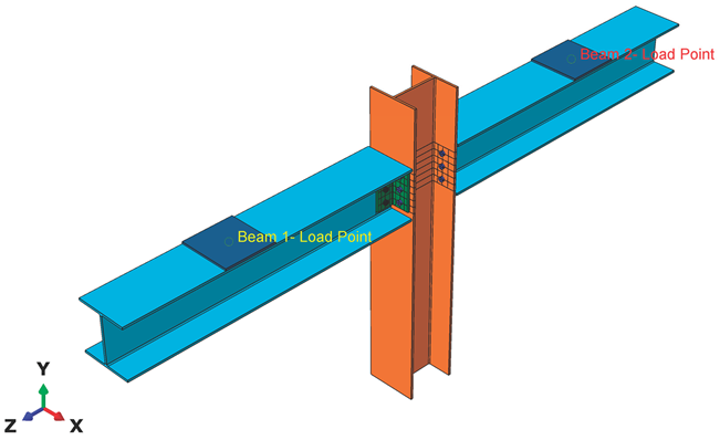
The experimental arrangement [5,8,21] shown in Figure 1 is used to validate the finite element (FE) model. The setup features a major-axis beam-to-column joint, where two cantilever beams are connected to a central column using a pair of web cleats. Vertical load is applied at the free ends of the back-to-back beams.
Both the beams and the column are 1500 mm long and consist of wide flange (WF) sections with dimensions of 254×254×9.53 mm. The web cleats, 192 mm in height, are cut from equal angle sections measuring 100×100×9.53 mm. The reinforcement in the cleats is aligned with the direction of the applied shear force. The beam centreline is positioned 1094 mm above the base of the column. The column base rests on a steel rocker fixture that permits in-plane rotation, justifying the assumption of a pinned connection. This pinned support ensures equal loading on both beams during testing.
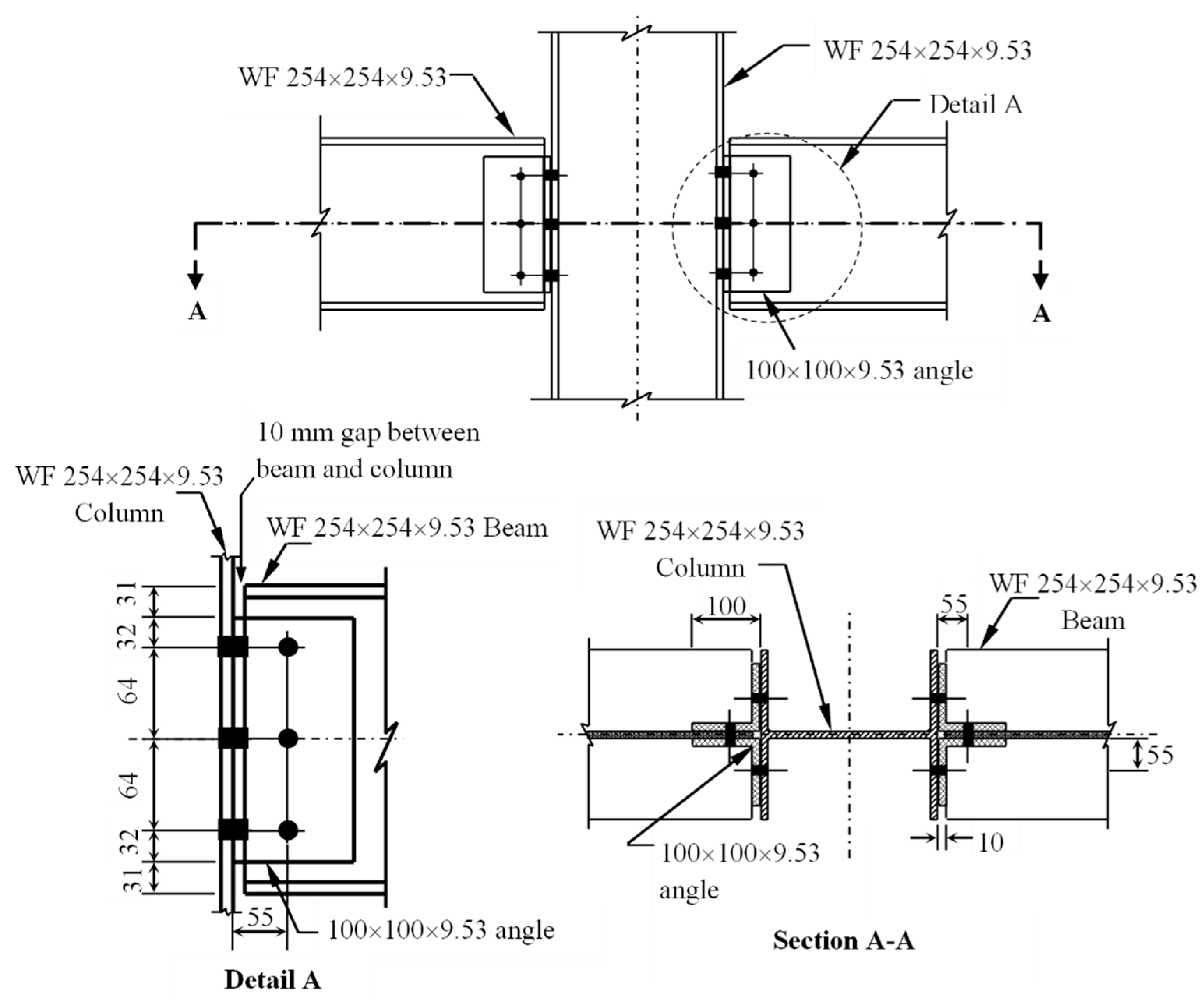
Figure 2.
Connection detailing for beam-to-column joints [21].
Figure 2.
Connection detailing for beam-to-column joints [21].
2.2. Creating Geometry
The beam-to-column joint geometry was modelled in ABAQUS by creating individual parts in the Parts module and assembling them in the Assembly module.
2.2.1. Beam and Column
Both beam and column components were defined within a three-dimensional deformable modelling space using the extrusion technique. The model was initiated at the centre of the grid, with the central point constrained using the Add Constraints feature to serve as a fixed reference.
An I-section was generated with the required dimensions by first defining a rectangular profile. The Fillet tool was then applied to introduce curvature at the junctions between the web and the top and bottom flanges. Once the section was finalised, it was extruded along the Z-direction (out-of-plane) to the specified length.
2.2.2. Web Cleat
The same procedure was applied to model the web cleats (angle sections) using deformed solid extrusion. An L-section was first defined, and the Fillet tool was used to represent the end curvature with the required radius. Once the section was established, it was extruded along the Z-direction to the specified length.
2.2.3. Steel Bolts
The bolt was modelled using the deformed solid revolution technique. In the Part Manager, a new part named “Bolt” was created with the following specifications: modelling space defined as three-dimensional, type set to deformable, shape specified as solid, and section generated through a full 360° revolution to produce the cylindrical geometry.
2.2.4. Steel Loading Plate
The loading plate was modelled as a rectangular section with sufficient thickness using solid extrusion. All parts were then assembled with the Translate and Rotate features to form the beam-to-column joint.
2.3. Material Properties
The Material module was used to define the mechanical properties of the model, including elastic, plastic, and damage criteria.
2.3.1. FRP beam, column and cleats – Elastic properties
The elastic properties of the composite are defined under Material > Mechanical > Elastic > Engineering Constants. For composites, isotropic elastic constants are insufficient to describe directional behaviour. Therefore, fibre-reinforced directional properties are introduced through engineering constants, lamina properties, or orthotropic material definitions to capture the anisotropic nature of the material.
Although material density does not influence static simulations, it must still be defined in the material properties, as it is required for dynamic explicit analyses, which are density-dependent. The elastic engineering constants for the different profiles are presented in Table 1.
2.3.2. FRP beam, column and cleats – Damage properties
In ABAQUS, the Hashin damage criterion is employed to model the failure behaviour of fibre-reinforced composites under various loading conditions. It is accessed via Mechanical > Damage for Fibre-Reinforced Composites > Hashin Damage Criterion. This criterion accounts for different failure modes in composite materials, including fibre tension, fibre compression, matrix tension, and matrix compression, providing a comprehensive approach to simulate material degradation.
Hashin damage in ABAQUS includes both damage evolution and damage stabilisation features. Damage evolution governs the progressive degradation of the material as failure initiates, while damage stabilisation helps prevent numerical instabilities during simulations. Typically, for composite materials, the stabilisation parameter is set smaller than the minimum time increment to ensure accurate and stable results.
2.3.3. Steel Bolts and Loading Plates
A bilinear elastic–perfectly plastic material model in ABAQUS was employed to define the material properties of the steel elements. The initial linear portion of the stress–strain curve was characterised by the modulus of elasticity up to the yield stress. Beyond this point, the material behaviour was idealised as perfectly plastic, continuing to yield until the ultimate stress was reached. This response is referred to as an elastic–perfectly plastic material behaviour.
The bolts and loading plates were modelled as steel components, exhibiting both elastic and plastic mechanical behaviour. The material properties were defined in ABAQUS following the sequence: Material Manager → Create Material → Density → Mechanical → Elastic → Plastic. The density of steel elements is taken as 7.85 × 10⁻⁹ tonne/mm3. For elastic-plastic followed sequence was adopted: Material Manager → Create Material → → Mechanical → Elastic → Plastic. The modulus of elasticity for all steel components was 210 GPa.
2.4. Assembling Individual Parts
The beam, column, web cleats, bolts, and loading plates were created as individual parts in ABAQUS. These parts were then assembled to replicate the physical beam-to-column joint tested in the experiments. The Translate, Rotate, Co-axial, and Co-linear constraints were applied to accurately position and align the components. Reference points were defined and tied to the loading locations, representing the hydraulic jacks used to apply loads in the experiments. Through this process, a complete three-dimensional model of the pultruded FRP beam-to-column joint was created as shown in Figure 3.
2.5. Defining Analysis Steps
The Step module in ABAQUS defines the type of analysis to be carried out. In this study, both static and cyclic analyses were considered. A new step was created through the Step Manager, with the time period set to 1. The incrementation parameters, including the initial, maximum, and minimum increment sizes, were specified, and nonlinearity was activated to allow for nonlinear analysis. Field outputs were defined using the Field Output Manager, with outputs requested for the composite layup and fracture response. There were three steps: Initial, bolt load and static general step. A bolt load of 12.5 kN was applied to bring the contacting surfaces together. This represented finger-tight condition in real life situation.
2.6. Defining Contact Interactions
Contact interactions in ABAQUS were defined using the penalty frictional formulation with the default hard contact pressure–overclosure relationship. The interaction property was created through the Interaction Property Manager by specifying tangential behaviour with a friction coefficient and normal behaviour with hard contact. For both GFRP and steel surfaces, a friction coefficient in the range of 0.2–0.3 was adopted.
Once the interaction property was defined, contact interactions were established either by using the Find Contact Pairs feature or by manually creating interactions through the Interaction Manager with general contact or surface-to-surface contact options, depending on the requirement.
Constraints were also defined within the interaction module. These included tie constraints, rigid body definitions, and coupling constraints. A tie constraint was created through the Constraint Manager by selecting the master and slave surfaces to bond the corresponding members. The loading plates were tied to the beam loading points on side and rigidly connected to a rigid reference point on the other side for load application.
Reference points were introduced to apply loads or displacements at unique nodal positions. This allowed the simulation to replicate the experimental loading conditions and capture the structural behaviour of the beam-to-column joint.
2.7. Boundary Conditions and Load Application
The model considered a column with a rocker-base pinned support, with two beams connected perpendicularly to the central column and treated as nominally pinned. The rocker base allowed rotation in all directions, releasing moments about the x-, y-, and z-axes.
The boundary condition for the column base was defined in the Load Module using the Boundary Condition Manager. An encastre condition was created and modified to act as a pinned support, restraining translational degrees of freedom (U1 = U2 = U3 = 0).
Loading was applied simultaneously to both beams in the negative y-direction as imposed displacements. Reference points were created at the loading locations to apply the displacement and rotation conditions. At these points, U1, U2, UR2, and UR3 were restrained, while U3 and UR1 were released. A displacement of U2 = –50 mm was applied to both beam loading points incrementally to replicate the experimental procedure.
2.8. Meshing and Mesh Sensitivity Analysis
The finite element (FE) models were developed and simulated using the commercial analysis software ABAQUS. The parts created included: (i) GFRP pultruded beam, (ii) GFRP pultruded column, (iii) GFRP web cleats, (iv) flange and web bolts (M16 grade 8.8 steel), and (v) steel loading plates. All parts were modelled with the exact sizes and dimensions used in the experimental study.
2.8.1. Meshing
Pultruded GFRP elements were meshed with eight-node continuum shell elements with reduced integration and default hourglass control (SC8R). Each ply was defined with three integration points through the thickness. The composite layups (consisting of rovings and mats) were treated as continuum shell elements, discretised into three-dimensional bodies. These elements possess only displacement degrees of freedom, but kinematic and internal energies contribute to their behaviour. As in conventional shell elements, stresses, strains, and damage variables were calculated at the integration points of each ply. Ply thickness was defined by the nodal spacing in the normal direction.
Steel parts, such as bolts and loading plates, were meshed with eight-node solid elements with reduced integration and default hourglass control (C3D8R). To reduce computational complexity, the steel components were assumed to be elastic isotropic, as the focus of the study was on the behaviour of the GFRP beam-to-column connection.
The GFRP beams were meshed with an element size of 15 × 15 mm, except at the web–flange junctions where a finer mesh of 5 × 5 mm was applied. Each beam contained 7,224 elements and 21,980 nodes. For two cantilever beams, this resulted in 14,448 elements and 43,960 nodes. Web cleats were meshed with 15 × 15 mm elements, except at the fillet radius (5 mm). Each cleat had 3,004 elements and 9,658 nodes; four cleats were used in total, giving 12,016 elements. Web bolts were meshed with a 2 mm size, producing 2,944 elements per bolt. With six web bolts, the total was 17,664 elements. Flange bolts were meshed with the same 2 mm size, giving 2,480 elements per bolt. With twelve flange bolts, this resulted in 29,760 elements. Each loading plate, meshed with 15 × 15 mm elements and 1 mm depth, contained 289 elements, giving 598 elements for both plates. In total, the complete model contained 81,712 elements. All meshed parts are shown in Figure 4.
Interfaces between the GFRP beam, the column base support, and the loading plates were defined using surface-to-surface contact with hard normal behaviour and a tangential friction coefficient of 0.2, minimising potential convergence issues due to prying action. The interface between the loading plates and the cantilever beams was defined using tie constraints, with appropriate degrees of freedom restrained. Loading was applied directly to the steel plates as displacement in the negative y-direction.
2.8.2. Mesh Sensitivity Analysis
Meshing is a critical stage in ABAQUS for achieving accurate and convergent results. While straight-edged geometries are relatively simple to mesh, curved edges, fillets, and bolt geometries require additional partitioning. The partitioning technique was therefore applied to subdivide the complex geometries into simpler sections, which were then meshed using the sweep method and medial axis algorithm.
Each part was meshed separately. Beams, columns, web cleats, and loading plates were meshed with global sizes of 7.5 mm and 15 mm, whereas bolts, being smaller components, were meshed with a 2 mm size. The finer 7.5 mm mesh produced results within 5% of the 15 mm mesh, but with a significantly higher computational cost. Therefore, the 15 mm mesh was adopted for the main model.
Mesh controls were assigned using hex or hex-dominated elements where possible, with structured or sweep techniques applied depending on geometry. Hourglass control was set to the enhanced/default method. Element deletion was enabled to simulate damage progression in the GFRP material using the Hashin damage criterion, capturing tensile and compressive fibre and matrix failures.
Finally, seeding was applied to activate meshing for each part and ensure consistent discretisation. Final meshed model of beam-column joint is shown in Figure 5.
2.9. Job Definition and Simulation
The Job module in ABAQUS was used to generate the input file, perform data checks, initiate the analysis, and monitor its progress. A job was created through the Job Manager by selecting Create, assigning a job name, and specifying the source as either the model or input file. The precision level was set to double to ensure numerical accuracy.
2.10. Visualisation and Result Extraction
Upon completion of the analysis, the Visualisation module in ABAQUS was used to extract results at unique nodal positions. Load–time and displacement–time curves were generated by selecting Create XY Data > Source > ODB Field Output > Variables > Position: Unique Nodal > Element/Nodes: Element Sets > Reference Point. These datasets were further processed using XY Data > Operate on XY Data with the Function option to derive moment–rotation values. The resulting data were combined through the Plot Expression feature to obtain the moment–rotation versus displacement response.
Failure modes were examined using the cut-through visualisation option, which enabled clear observation of local damage in the web cleats. Hashin damage output was also reviewed, providing insight into fibre and matrix failure locations within the cleat sections of the joint configuration.
2.11. Validaiton with Experiments
This section presents the numerical results of the simulation, illustrating the configuration and behaviour of the GFRP beam-to-column joint reinforced with GFRP web cleats. The analysis aims to assess both the linear and non-linear moment–rotation response, as well as the progressive damage predicted by Hashin’s failure criterion. The numerical results, including moment–rotation (M–φ) curves, are compared with the experimental data reported by Qureshi and Mottram [21] to validate the numerical model.
In this study, the experimental beam-to-column pultruded FRP joints reported by Qureshi and Toby Mottram (2015) were reproduced numerically to simulate the same configuration of a GFRP pultruded beam-to-column connection with GFRP web cleats. The connection consisted of two cantilever beams, each with a span of 1.5 m, connected perpendicularly to a central column of the same height (1500 mm). The column section was 254 × 254 × 9.53 mm, and the web cleats were 100 × 100 × 9.53 mm equal-angle profiles. All structural members were manufactured from GFRP, while the bolts, nuts, and washers used in the connections were steel, consisting of M16 grade 8.8 bolts with 3 mm thick washers. This full-scale joint configuration was modelled numerically using the finite element package ABAQUS.
2.11.1. Moment Versus Rotation Curves
Both static and cyclic non-linear analyses were performed to determine the moment-resistance capacity, the initial stiffness (Si), and the ultimate moment (Mmax). The initial stiffness was calculated using the expression Si=Mi/φi, where Mi and φi correspond to the moment and rotation at the linear stage of the connection. The analysis also provided the maximum rotation (φmax) and the failure modes of the joint, including the delamination points of the sections. Bolt loads and stresses were not included, as the model focuses on the behaviour of the GFRP pultruded section.
Figure 6 and Figure 7 present the M-φ curves for the numerical and experimental results for the same joint configurations. The left-hand rotation curve shows the ultimate moment-carrying capacity of the joint. The maximum moment (Mmax) from the numerical analysis was approximately 1.78 kNm, compared to 1.76 kNm in the experiment, representing a variation of around 5%. The maximum rotation (φmax) was 43.40 mrad numerically, slightly higher than the experimental value of 42.60 mrad, a difference of approximately 3%.
The right-hand rotation curve illustrates the maximum moment capacity as approximately 1.80 kNm for both numerical and experimental results. When comparing the maximum rotation, the numerical value of 49.17 mrad shows a small variation from the experimental value of 50.25 mrad. The moment–rotation behaviour on both the left and right sides from the FE analysis showed close agreement with the experimental results.
2.11.2. Delamination and Failure Modes
The failure modes and patterns observed in the numerical models closely matched those in the experimental setups, although the fracture values in the experiments were slightly lower than those predicted numerically. Failure was predominantly governed by shear stresses, and Hashin’s failure criterion captured compression, tension, fibre, and matrix failures in the numerical simulation. In the model, damaged elements are colour-coded: red indicates fully damaged elements (D = 1.0), while blue represents undamaged elements (D = 0.0).
In the experimental setup, a hairline crack was observed at the top fillet radius of the web cleats following the initial stiffness (Si) in the linear region. The stiffness reduced as non-linearity developed in the moment–rotation curve. Similarly, in the numerical simulation, delamination occurred at the top fillet radius of the web cleat, although the numerical values differed slightly. According to Hashin’s criterion, tension failures were typically complete, while compression failures were partial (D = 0.5–0.75). Matrix and fibre failures were fully developed with D = 1.0. Compressive and tensile damage in web cleats is presented in Figure 8, Figure 9, Figure 10 and Figure 11.
Overall, the numerical and experimental results were in close agreement, with variations below 10%. The validated numerical model was therefore used for subsequent parametric studies to investigate moment–rotation behaviour, joint stiffness, and potential improvements to the GFRP pultruded beam-to-column joint configuration.
3. Parametric Study
A parametric study was conducted by varying the connection geometry, bolt size, and bolt-hole clearance. The aim was to examine in detail the behaviour of the FRP pultruded beam-to-column connection with FRP web cleats by adjusting key parameters that influence its performance. This examination sought to evaluate the effects of these parameters on stiffness, strength, ductility, and failure modes, and to assess the sensitivity of the connection response to such variations.
In general, several connection techniques exist for structural joints. Welded connections are common in steel structures but are not feasible for FRP frames, as the heat generated during welding would damage the glass fibres and resin in pultruded elements. Bonded connections have been reported in the literature—for example, by Zheng [24] —as adequate for pultruded FRP sections, providing uniform stress transfer. However, their long-term durability is uncertain, which makes them less suitable for FRP applications. Consequently, bolted connections, adapted from steel structures, are most widely used. In such connections, bolt-hole clearance plays an important role in accommodating stresses around the bolt holes.
Previous studies [4,25,26,27] identified three key parameters influencing the behaviour of bolted FRP connections: connection geometry, bolt size and bolt-hole clearance. In this study, the connection geometry, fibre orientation, and bolt-hole clearance were systematically varied to evaluate their influence on the performance of the beam-to-column joint.
3.1. Connection Geometry
In this parametric study, the overall connection configuration and dimensions were modified to reflect the availability of commercially produced sections for potential future applications. The lengths and widths of the FRP beam and column sections were kept constant, while the size and thickness of the web cleat leg angle were varied. For this numerical simulation, an equal-leg angle web cleat of 150 × 150 × 12.7 mm was used, whereas the experimental beam-to-column tests in Qureshi and Mottram [21] employed a 100 × 100 × 9.53 mm web angle.
The model was designated as Wmj254_3M16_Wc150 (where WC denotes web cleat), representing a major-axis beam-to-column joint with a 254 × 254 × 9.53 mm wide-flange FRP section, connected using three M16 grade 8.8 bolts and a 150 × 150 × 12.7 mm web cleat.
The moment–rotation (M–φ) curve for the model Wmj254_3M16_WC150, shown in Figure 12, represents the joint with a 150 × 150 × 12.5 mm equal-leg angle web cleat. For this configuration, damage initiation was observed in the left beam at a rotation of approximately 7 mrad and a moment of about 0.75 kNm. Non-linearity began at around 0.65 kNm, with no delamination detected up to that point. The subsequent drop in moment indicates creep relaxation in the web cleats, followed by progressive damage. At the same stage, the right beam exhibited a rotation of 6.9 mrad with a corresponding moment of approximately 0.71 kNm.
The M–φ responses of both joints (left and right) remained comparable until delamination of the FRP material occurred. The failure was attributed to extensive delamination damage at the top of the web cleats, particularly around the fillet radius. The initial stiffness (Si) for this configuration was obtained directly from the numerical curve. In ABAQUS, bolt and hole effects are automatically accounted for, eliminating the need for slip–rotation compensation, which was necessary in the experimental tests.
These results, together with the M–φ response, indicate that the failure moment in this case is slightly higher than that of the control experiment. Therefore, increasing the thickness of the web cleats enhances the initial stiffness (Si), although the ultimate failure remains governed by delamination.
3.2. Bolt Size
In the experimental setup [21], M16 grade 8.8 bolts with 3 mm thick washers were used. For this parametric study, the bolts were replaced with M18 grade 8.8 bolts while retaining the 3 mm thick washers to study the behaviour of joint with a different bolt size. The model was designated as Wmj254_3M18_BS (Bolt Size).
The moment–rotation (M–φ) curve for the model Wmj254_3M18_BS, shown in Figure 13, illustrates the joint configuration with three M18 grade 8.8 bolts and 3 mm thick washers. The connection comprised two cantilever beams and a central column of 254 × 254 × 9.53 mm, connected using 100 × 100 × 9.53 mm equal-leg angle web cleats. The only alteration in this configuration was the increase in bolt size, which also required an increase in hole diameter with the appropriate clearance.
For this model, damage initiation in the left beam was observed at a rotation of approximately 8 mrad and a moment of 0.95 kNm. Non-linearity began at around 0.75 kNm, and a delamination point occurred early at a low moment. This was attributed to the larger bolt diameter, where significant pre-tension in the shank caused brittle behaviour. On the right beam, delamination onset was recorded at around 0.87 kNm and 11.70 mrad.
Slip rotation was detected in the FEM simulation but compensated automatically by the convergence solver, and the corrected response was obtained. The ultimate moment resistance reached approximately 2.0 kNm on both sides. From the M–φ curve, the initial stiffness (Si) was determined, along with the initial moment (Mi) and initial rotation (φi) prior to delamination. Failure occurred at the top of the web cleats, concentrated around the curvature of the fillet radius.
When considering bolt size as the key parameter, slip rotation would typically be expected. However, no significant slip was observed in this case. This finding aligns with the observations of Qureshi and Mottram [21], who noted that slip rotation represents a critical consideration in the design of simple pultruded FRP joints, requiring careful preparation and allowance in practical applications.
3.3. Bolt-Hole Clearance
In the parental model used for experimental validation, the bolt-hole clearance was defined as 0 mm in the beam and 1 mm in the column flange to facilitate assembly of the joint components. In this parametric study, the clearance was increased by 1 mm, giving 2 mm clearance in the column flanges while maintaining 0 mm clearance in the beam. The model was designated as Wmj254_3M16_BC2.0 (Bolt-Hole Clearance).
The moment–rotation (M–φ) curve for the model Wmj254_3M16_BC2.0, shown in Figure 14, illustrates the same connection configuration used to validate the numerical model. The joint consisted of a 254 × 254 × 9.53 mm cantilever beam and column made of GFRP pultruded sections, connected with 100 × 100 × 9.53 mm equal-leg FRP angles. In the experiment, M16 grade 8.8 steel bolts were used; in this parametric model, the alteration introduced was a bolt-hole clearance of 2 mm on both the beam web and the column flange, following observations by Zheng [24] that bolt-hole clearance significantly affects the moment–rotation response and initial stiffness.
Damage initiation in this model was observed at a moment of approximately 0.80 kNm and a rotation of 7 mrad on the left beam. On the right beam, the onset occurred at around 0.64 kNm and 6 mrad. Slip rotation due to bolt-hole clearance was present, arising from prying action, but this effect was automatically compensated by the non-linear convergence solver in ABAQUS.
The ultimate moment resistance showed no significant variation, reaching 1.64 kNm and 1.80 kNm for the left and right beams respectively. The initial stiffness (Si) values were obtained from the M–φ curves, along with the initial moment (Mi) and rotation (φi) values prior to delamination. The failure mode was consistent with other numerical models, with delamination occurring at the fillet curvature radius of the web cleats.
3.4. Joint Properties
The primary objective of each numerical model was to evaluate the joint properties, including parametric models where key factors were altered to examine their influence on the joint behaviour and the moment resistance of GFRP pultruded sections. The maximum and minimum values of the initial stiffness (Si) were calculated using the relation (Si=Mi/φi) where Mi and φi are obtained from the linear region of the M–φ curve.
The damage onset properties, defined as the moment (Mj), rotation (φj ), and stiffness (Sj) at the point where material failure was first observed, were also recorded. In addition, the maximum moment capacity (Mmax) and the corresponding maximum rotation (φmax) were identified for each joint configuration.
From Table 7, Table 8 and Table 9, the results of the three numerical models with altered key factors influencing the joint properties of the connection are summarised from their respective simulations and moment–rotation curves. For all three models, the initial moment (Mi) was found to be approximately 0.8 kNm, with a coefficient of variation (CV) of less than 5%. The average maximum moment capacity (Mmax) recorded at failure was 2.48 kNm, 2.04 kNm, and 1.71 kNm for the modified web cleat thickness and size, bolt size, and bolt-hole clearance models respectively, with CV < 10%. These results indicate that the introduced parametric changes did not significantly alter the overall moment resistance of the beam-to-column connection configuration.
The major variation identified from the full-scale model simulations was in the maximum rotation ((φmax), which ranged from 27 to 49 mrad. The maximum displacement was limited to 50 mm in order to obtain a clearer understanding of the connection behaviour. The CV of the initial stiffness (Si) was less than 3% for the Wmj254_3M16_WC150 and Wmj254_3M18_BS models. However, for the Wmj254_3M16_BC model, the CV was about 12%, a variation that occurred only within the linear region of the moment–rotation curve, without delamination in the web cleats. To enhance joint performance beyond the nonlinear stage, the mean and CV of the stiffness at damage onset (Sj) were observed to vary by less than 10% across all three models, demonstrating comparable behaviour.
The key finding of this parametric numerical analysis is that stiffness is more sensitive to changes in connection parameters than moment resistance. One of the main objectives of this study is therefore to develop an optimised connection design with respect to the joint properties of pultruded FRP beam-to-column connections using web cleats. Furthermore, increasing joint stiffness can be achieved by adjusting the web cleat geometry—such as increasing thickness and leg length—or by employing larger-diameter bolts. These adjustments enhance the load-carrying capacity and the initial stiffness of the joint, while appropriate design optimisation ensures material costs and overall structural weight remain reasonably low.
3.5. Joint Classification
The rotational stiffness (Si) values obtained from the tables classify the joints as nominally pinned connections. According to Eurocode 3, Part 1-8 [28], the initial rotational stiffness at service load, Si,ini, is calculated using the expression Si = Mi/ϕi. Based on the design specification for steel connections, if Si,ini · L/EI ≤ 0.5, where EI/L is the flexural stiffness of the beam member, the joint is considered nominally pinned.
For a beam with a span-to-depth ratio of 20, the span (L) is 5.90 m for a 254 mm deep wide flange (WF) section. From the property table, the flexural modulus of elasticity (E) of the WF section is 27.6 kN/mm², and the second moment of area (I) is approximately 8.34 × 10⁷ mm⁴. This gives a nominal pinned stiffness of about 230 kNm/rad.
When the span is increased to 10 m, the stiffness limit reduces to about 120 kNm/rad for the 254×254×9.53 mm WF section. In comparison, the three numerical models produced initial stiffness (Si) values in the range of 94–111 kNm/rad. These values fall within the defined limits, confirming that the joint detailing is classified as nominally pinned.
4. Conclusions
The following conclusions are drawn from this research:
- The finite element model developed in ABAQUS successfully reproduced the moment–rotation response, stiffness, and failure modes of pultruded FRP beam-to-column joints with FRP web cleats. Numerical predictions showed good agreement with experimental results, with differences within 10%.
- Delamination at the top fillet radius of the web cleats was identified as the governing failure mode. Hashin’s progressive damage model accurately captured fibre and matrix failures, confirming its suitability for simulating the brittle failure mechanisms of FRP materials.
- The parametric study demonstrated that variations in cleat size, bolt size, and bolt-hole clearance had limited influence on ultimate moment capacity. However, these parameters significantly affected joint stiffness, indicating that connection detailing plays a key role in serviceability performance.
- Increasing cleat thickness and bolt diameter improved initial stiffness, while bolt-hole clearance introduced slip effects but did not significantly alter ultimate strength.
- The rotational stiffness values obtained from all numerical models fall within the limits defined by Eurocode 3, classifying the joints as nominally pinned.
- The validated FE approach provides a practical framework for evaluating FRP joint performance, reducing the need for extensive physical testing. It also offers a basis for optimising connection design in pultruded FRP structures and supports the future development of design guidelines.
Author Contributions
Conceptualization, writing—original draft preparation, writing—review and editing, supervision and project administration Jawed Qureshi; methodology, software, validation, formal analysis, investigation and data curation Karthick Murugan Mahendran. All authors have read and agreed to the published version of the manuscript.
Acknowledgments
The authors would like to thank the University of East London for providing the facilities that made this research possible.
Conflicts of Interest
The authors declare no conflicts of interest.
References
- Bank, L.C. Composites for Construction - Structural Design with FRP Materials; John Wiley & Sons: Hoboken, New Jersey, USA, 2006;
- Mottram, J.T. Does Performance-Based Design with FRP Components and Structures Provide Any New Benefits and Challenges? Struct. Eng. 2011, 89.
- Mosallam, A. Design Guide for FRP Composite Connections; American Society of Civil Engineers: Reston, VA, 2011; ISBN 978-0-7844-0612-0.
- Turvey, G.J.; Cooper, C. Review of Tests on Bolted Joints between Pultruded GRP Profiles. Proc. Inst. Civ. Eng. Struct. Build. 2004, 157, 211–233. [CrossRef]
- Mottram, J.T.; Zheng, Y. State-of-the-Art Review on the Design of Beam-to-Column Connections for Pultruded Frames. Compos. Struct. 1996, 35, 387–401. [CrossRef]
- Turvey, G.J. Analysis of Pultruded Glass Reinforced Plastic Beams with Semi-Rigid End Connections. Compos. Struct. 1997, 38, 3–16. [CrossRef]
- Bank, L.C.; Mosallam, A.S.; Gonsior, H.E. Beam-to-Column Connections for Pultruded FRP Structures. In Proceedings of the Proc. 1st Materials Engineering Congress, ASCE; Denver, USA, 1990; pp. 804–813.
- Mottram, J.T.; Zheng, Y. Further Tests on Beam-to-Column Connections for Pultruded Frames: Web-Cleated. J. Compos. Constr. 1999, 3, 3–11. [CrossRef]
- Qureshi, J.; Nadir, Y.; John, S.K. Bolted and Bonded FRP Beam-Column Joints with Semi-Rigid End Conditions. Compos. Struct. 2020, 247, 112500. [CrossRef]
- Qureshi, J.; Nadir, Y.; John, S.K. Cyclic Response of Bolted and Hybrid Pultruded FRP Beam-Column Joints between I-Shaped Sections. Fibers 2021, 9, 66. [CrossRef]
- Qureshi, J. A Review of Fibre Reinforced Polymer Structures. Fibers 2022, 10, 27. [CrossRef]
- Eskenati, A.R.; Mahboob, A.; Bernat-Maso, E.; Gil, L. Experimental and Numerical Study of Adhesively and Bolted Connections of Pultruded GFRP I-Shape Profiles. Polymers (Basel). 2022, 14. [CrossRef]
- Matharu, N.S.; Mottram, J.T. Plain and Threaded Bearing Strengths for the Design of Bolted Connections with Pultruded FRP Material. Eng. Struct. 2017, 152. [CrossRef]
- Coelho, A.M.G.; Mottram, J.T. Numerical Evaluation of Pin-Bearing Strength for the Design of Bolted Connections of Pultruded FRP Material. J. Compos. Constr. 2017, 21. [CrossRef]
- Tang, J.; Feng, P.; Wang, Q. Beam-Column Joints of FRP Pultruded Profiles: State-of-the-Art Review, Performance Evaluation, and Design Method. Compos. Struct. 2025, 370, 119250. [CrossRef]
- Ascione, F.; D’Aniello, M.; Feo, L.; Granata, L.; Landolfo, R. A Novel Ductile Connection for FRP Pultruded Beam-to-Column Assemblies. Compos. Struct. 2024, 337, 118091. [CrossRef]
- Qureshi, J.; Mottram, J.T. Resin Injected Bolted Connections: A Step towards Achieving Slip-Resistant Joints in FRP Bridge Engineering. In Proceedings of the FRP Bridges Conference, NetComposites, 13-14 Sep 2012; London, UK, 2012.
- Qureshi, J.; Mottram, J.T. Response of Beam-to-Column Web Cleated Joints for FRP Pultruded Members. J. Compos. Constr. 2014, 18, 04013039. [CrossRef]
- Qureshi, J.; Mottram, J.T.; Zafari, B. Robustness of Simple Joints in Pultruded FRP Frames. Structures 2015, 3, 120–129. [CrossRef]
- Zafari, B.; Qureshi, J.; Mottram, J.T.; Rusev, R. Static and Fatigue Performance of Resin Injected Bolts for a Slip and Fatigue Resistant Connection in FRP Bridge Engineering. Structures 2016, 7, 71–84. [CrossRef]
- Qureshi, J.; Mottram, J.T. Moment-Rotation Response of Nominally Pinned Beam-to-Column Joints for Frames of Pultruded Fibre Reinforced Polymer. Constr. Build. Mater. 2015, 77, 396–403. [CrossRef]
- Creative Composites The New and Improved PulTex Pultrusion Design Manual; Creative Pultrusions Inc.: Alum Bank, PA, USA, 2024;
- Bishay-Girges, N.W. Improved Steel Beam-Column Connections in Industrial Structures. Eng. Technol. Appl. Sci. Res. 2020, 10, 5126–5131. [CrossRef]
- Zheng, Y. Connection Behaviour and Frame Analysis for Structures of Pultruded Profile, PhD Thesis, University of Warwick, Coventry, UK, 1998.
- Abd-El-Naby, S.F.M.; Hollaway, L. The Experimental Behaviour of Bolted Joints in Pultruded Glass/ Polyester Material. Part 2: Two-Bolt Joints. Composites 1993, 24, 539–546. [CrossRef]
- Abd-El-Naby, S.F.M.; Hollaway, L. The Experimental Behaviour of Bolted Joints in Pultruded Glass/ Polyester Material. Part 1: Single-Bolt Joints. Composites 1993, 24, 531–538. [CrossRef]
- Hollaway, L.C.; Head, P.R. Advanced Polymer Composites and Polymers in the Civil Infrastructure; First edit.; Elsevier Science: Oxford, UK, 2001; ISBN 978-0-08-043661-6.
- 28. BS EN 1993-1-8:2005 Eurocode 3: Design of Steel Structures - Part 1-8: Design of Joints; British Standards Institution: London, UK, 2005;
Figure 1.
Test setup using back-to-back cantilever beams [21].
Figure 1.
Test setup using back-to-back cantilever beams [21].
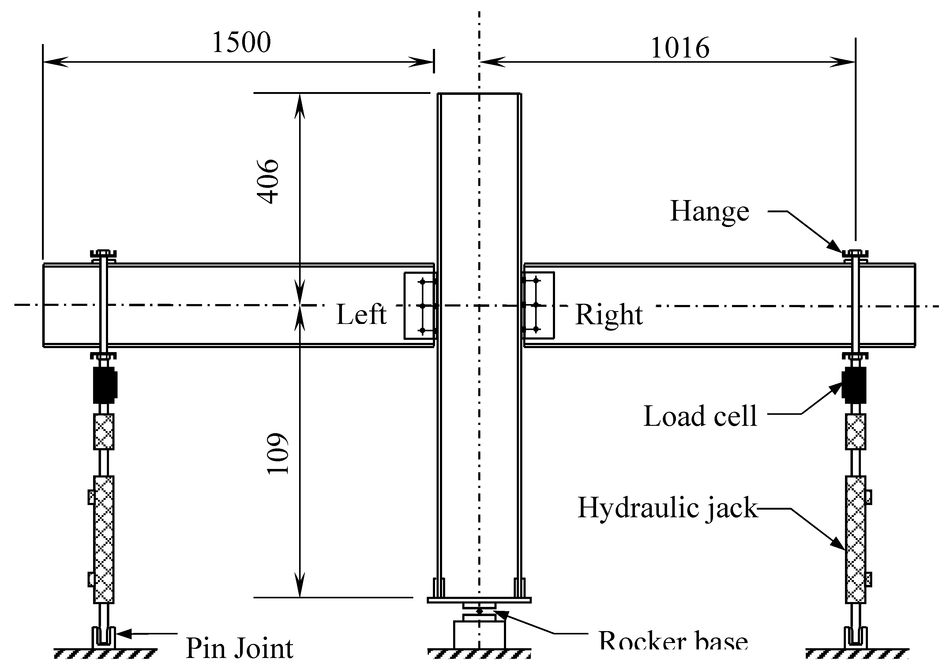
Figure 3.
Beam-to-column joint after assembling all parts including loading plates.
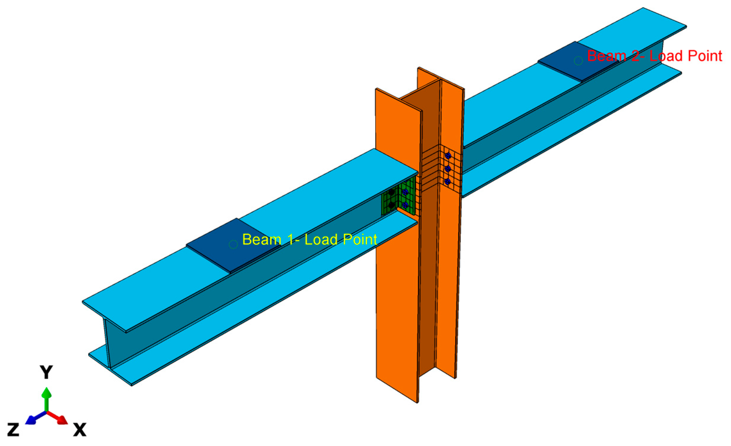
Figure 4.
Meshing individual parts of beam-to-column sub-assembly: (a) FRP beam with bolt holes; (b) FRP column with bolt holes; (c) Steel bolt for beam web; (d) Steel bolt for column flange; (e) FRP web cleat (leg-angle connecting beam with column); (f) Steel loading plate.
Figure 4.
Meshing individual parts of beam-to-column sub-assembly: (a) FRP beam with bolt holes; (b) FRP column with bolt holes; (c) Steel bolt for beam web; (d) Steel bolt for column flange; (e) FRP web cleat (leg-angle connecting beam with column); (f) Steel loading plate.
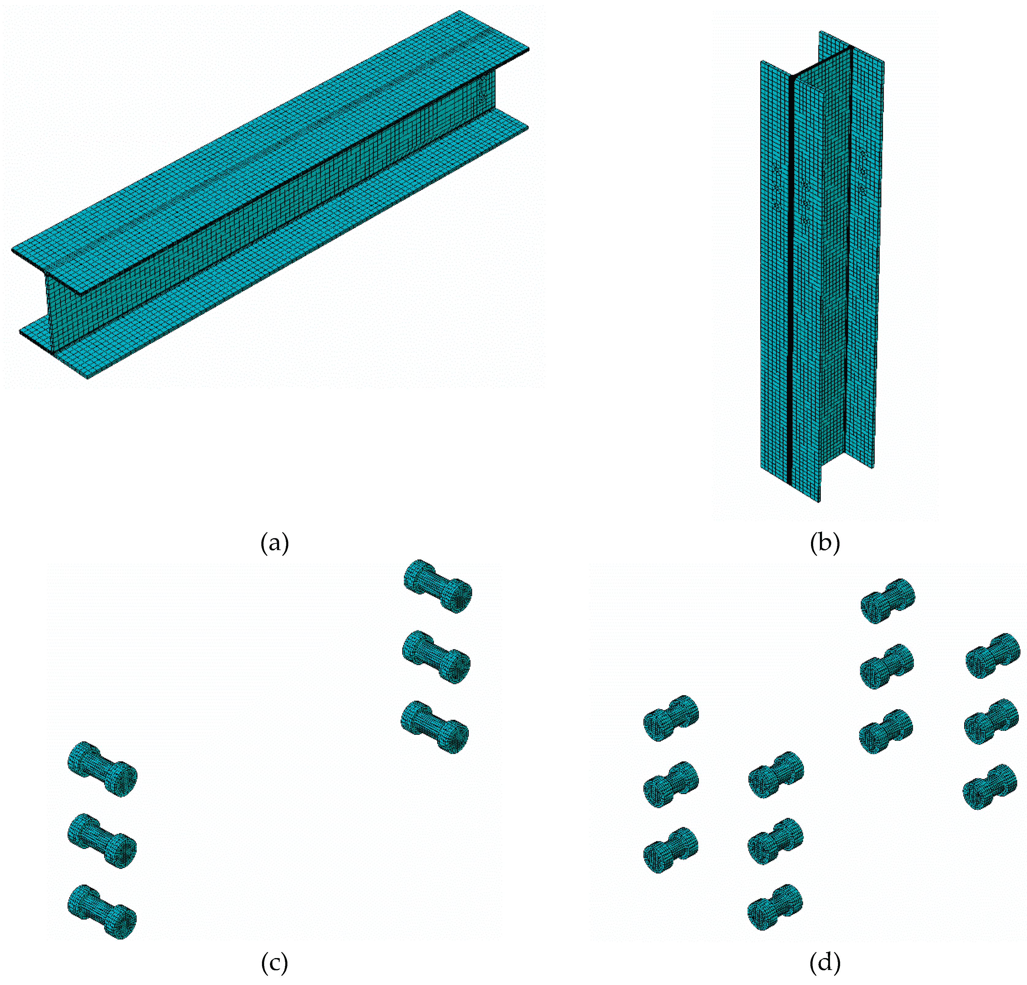
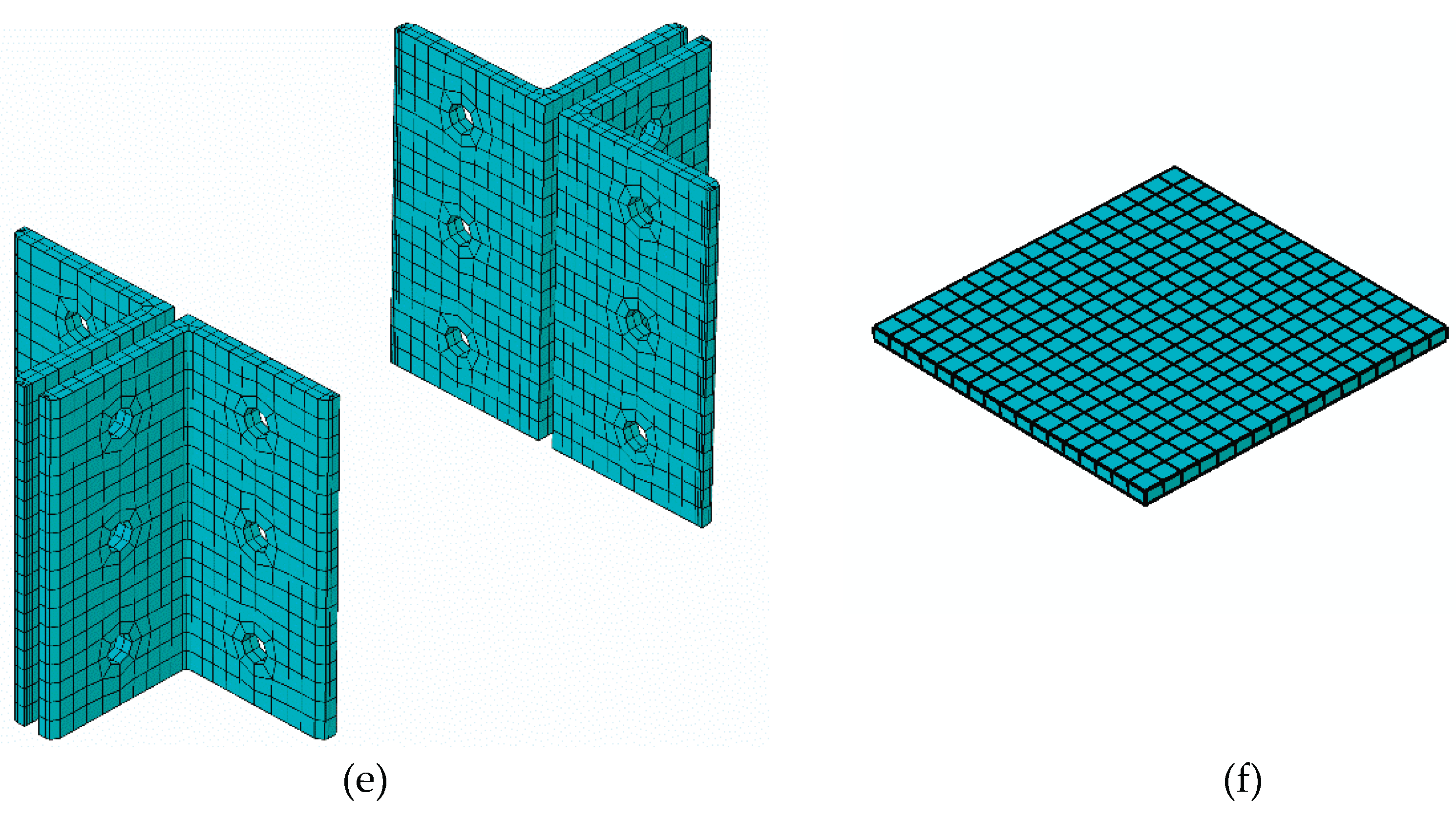
Figure 5.
Final meshed finite element model for FRP beam-column sub-assembly.
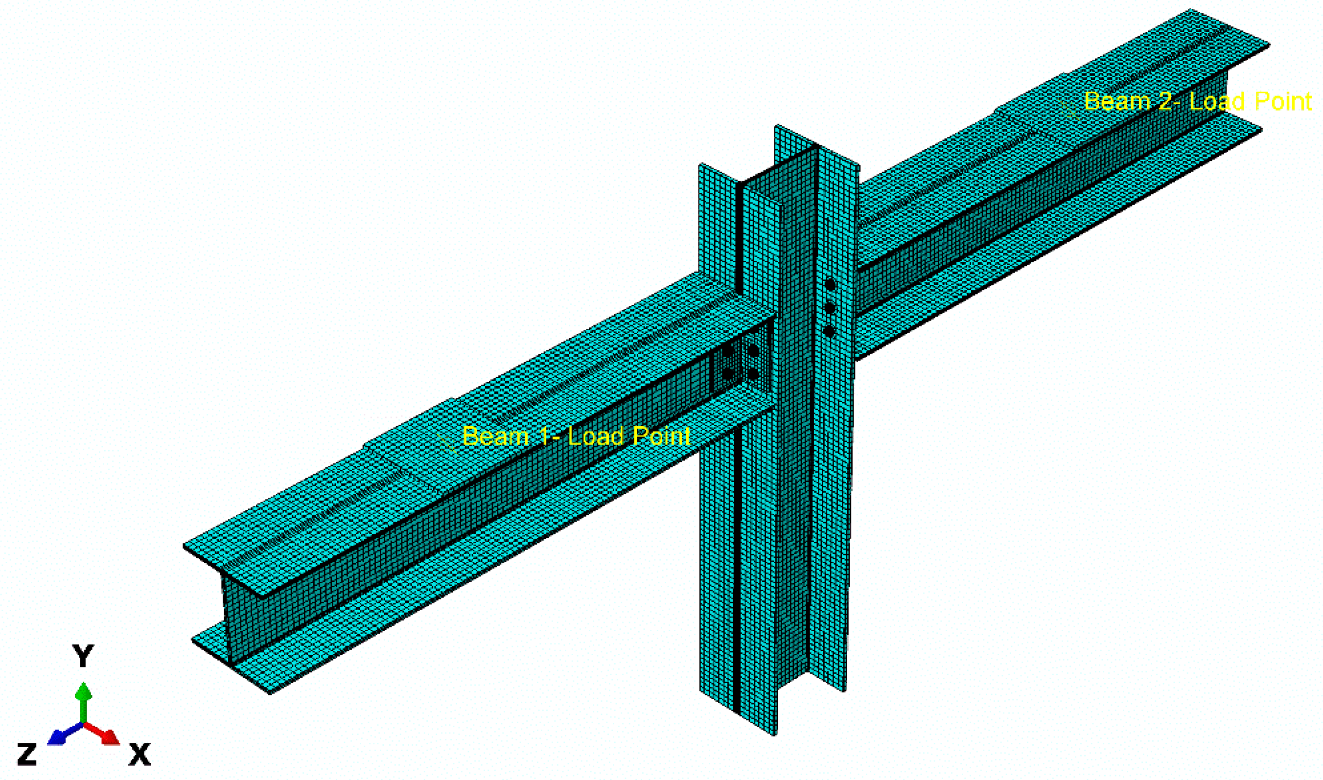
Figure 6.
Experiment versus numerical moment-rotation curve for left side joint
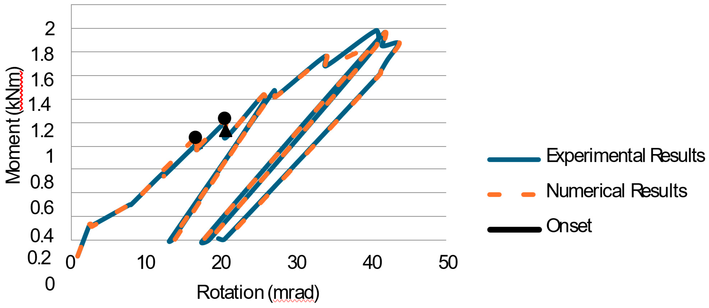
Figure 7.
Experiment versus numerical moment-rotation curve for left side joint
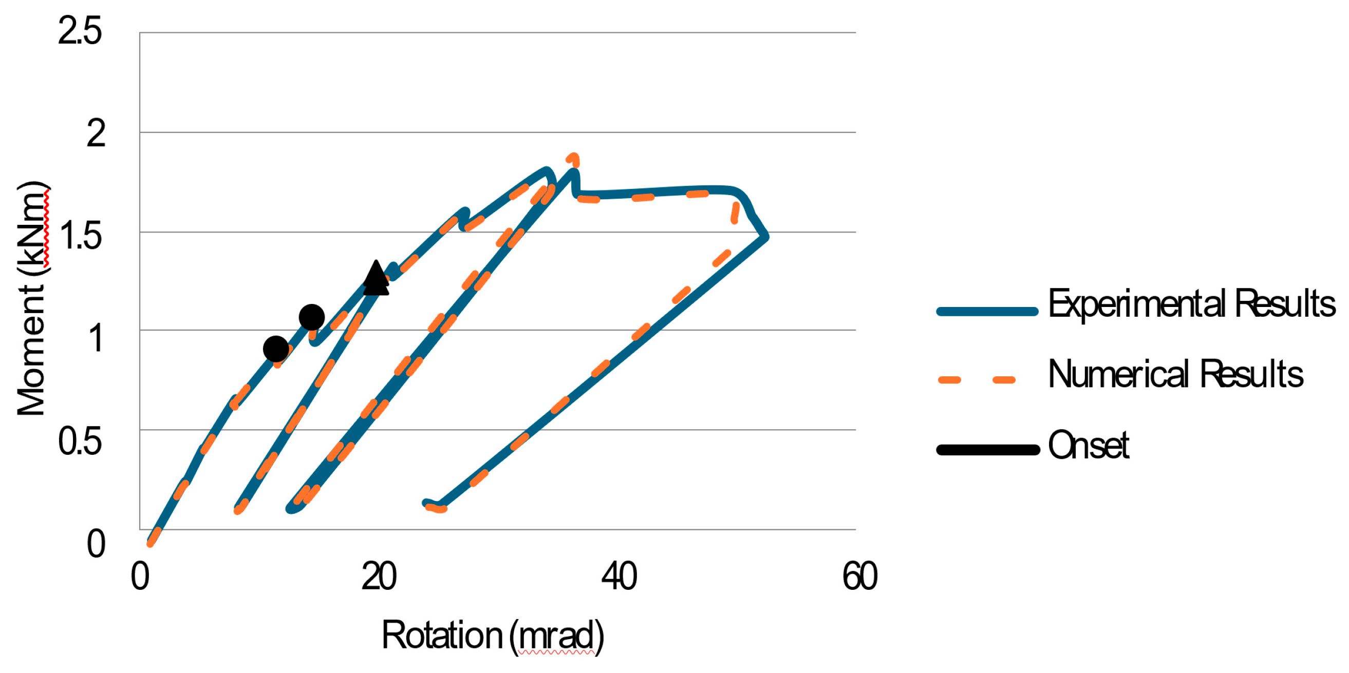
Figure 8.
Hashin's Compressive Fibre Failure at web cleat top
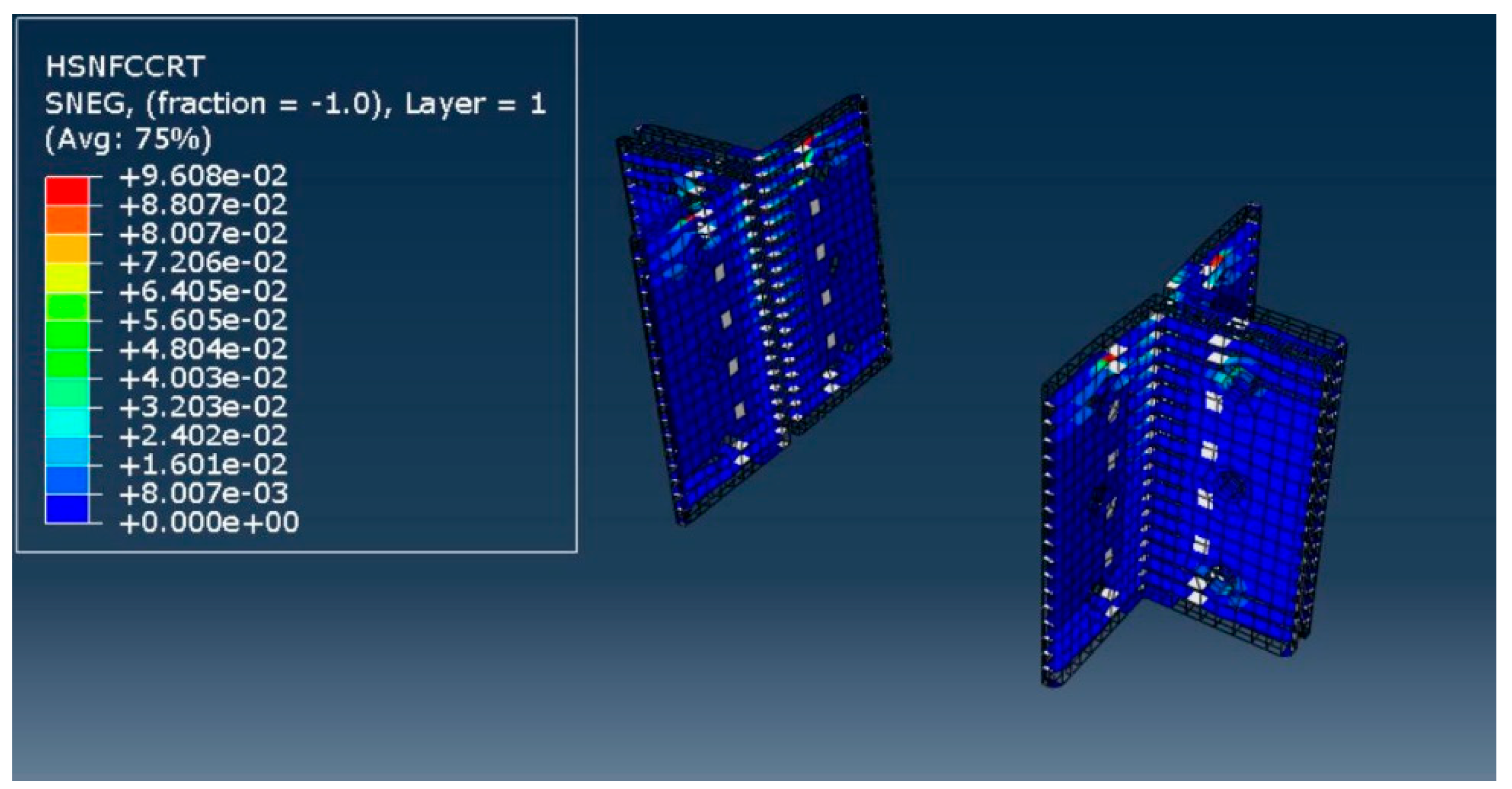
Figure 9.
Hashin's Tensile Fibre Failure at in the vicinity of Web cleat hole
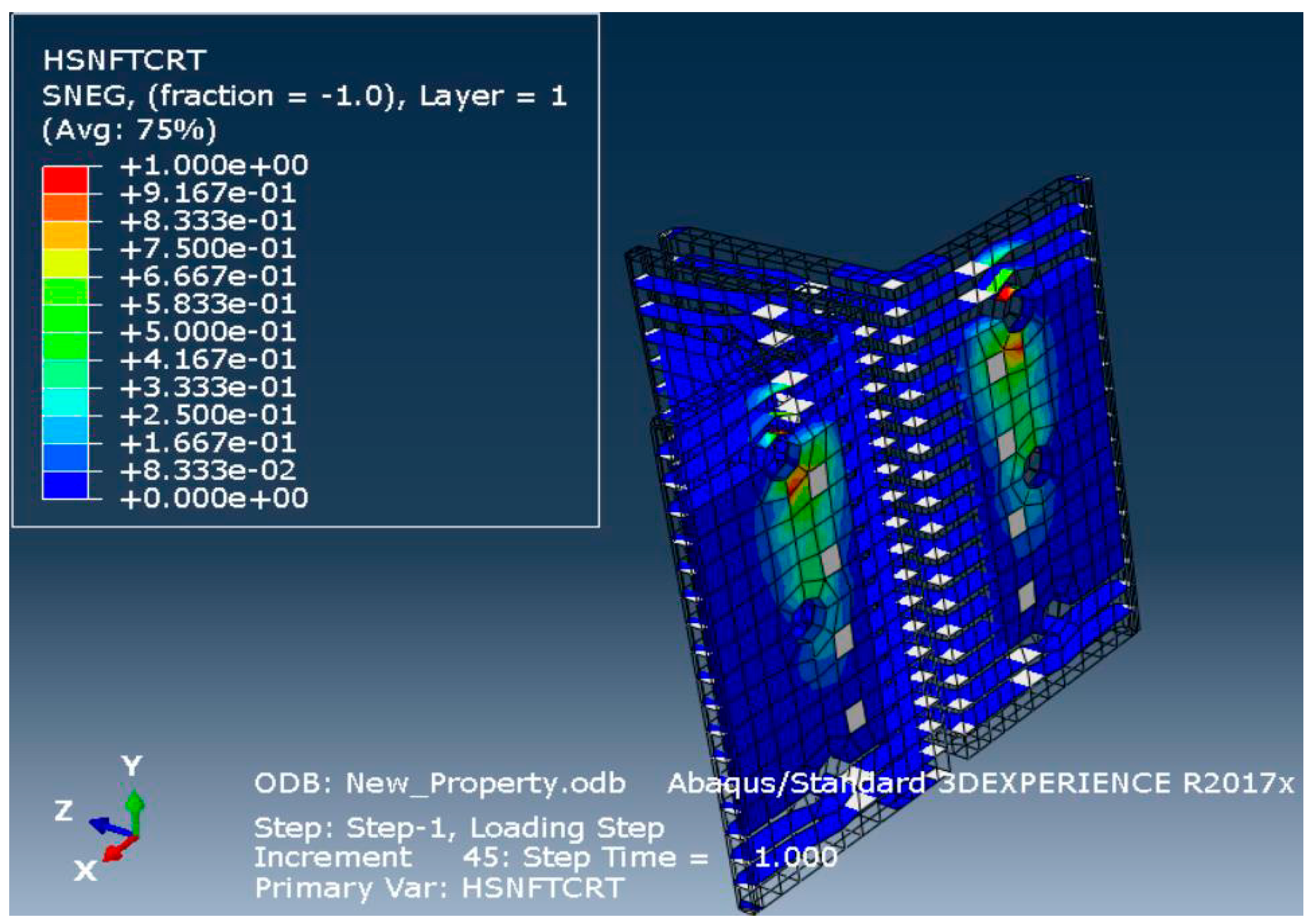
Figure 10.
Hashin's Compressive Matrix failure at web cleat
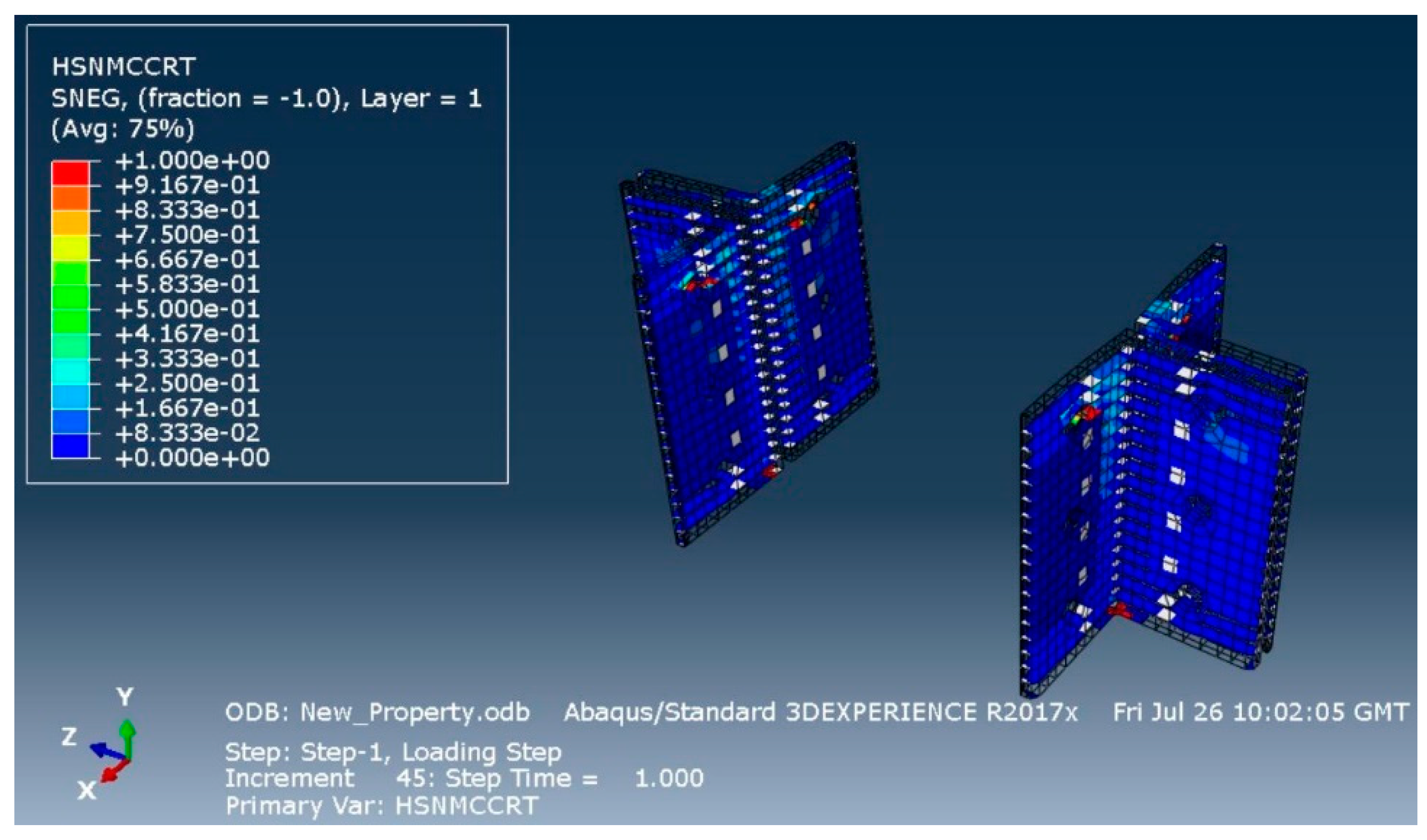
Figure 11.
Hashin's Tensile Matrix Failure at the top fillet radius of the web cleat
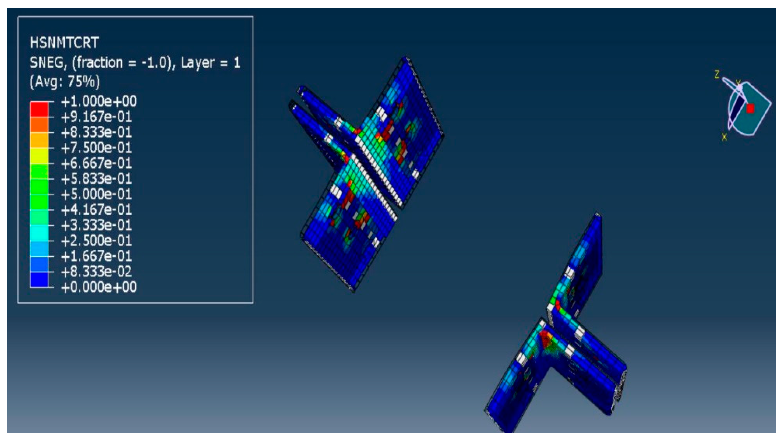
Figure 12.
Moment-rotation behaviour for the model Wmj254_3M16_WC150
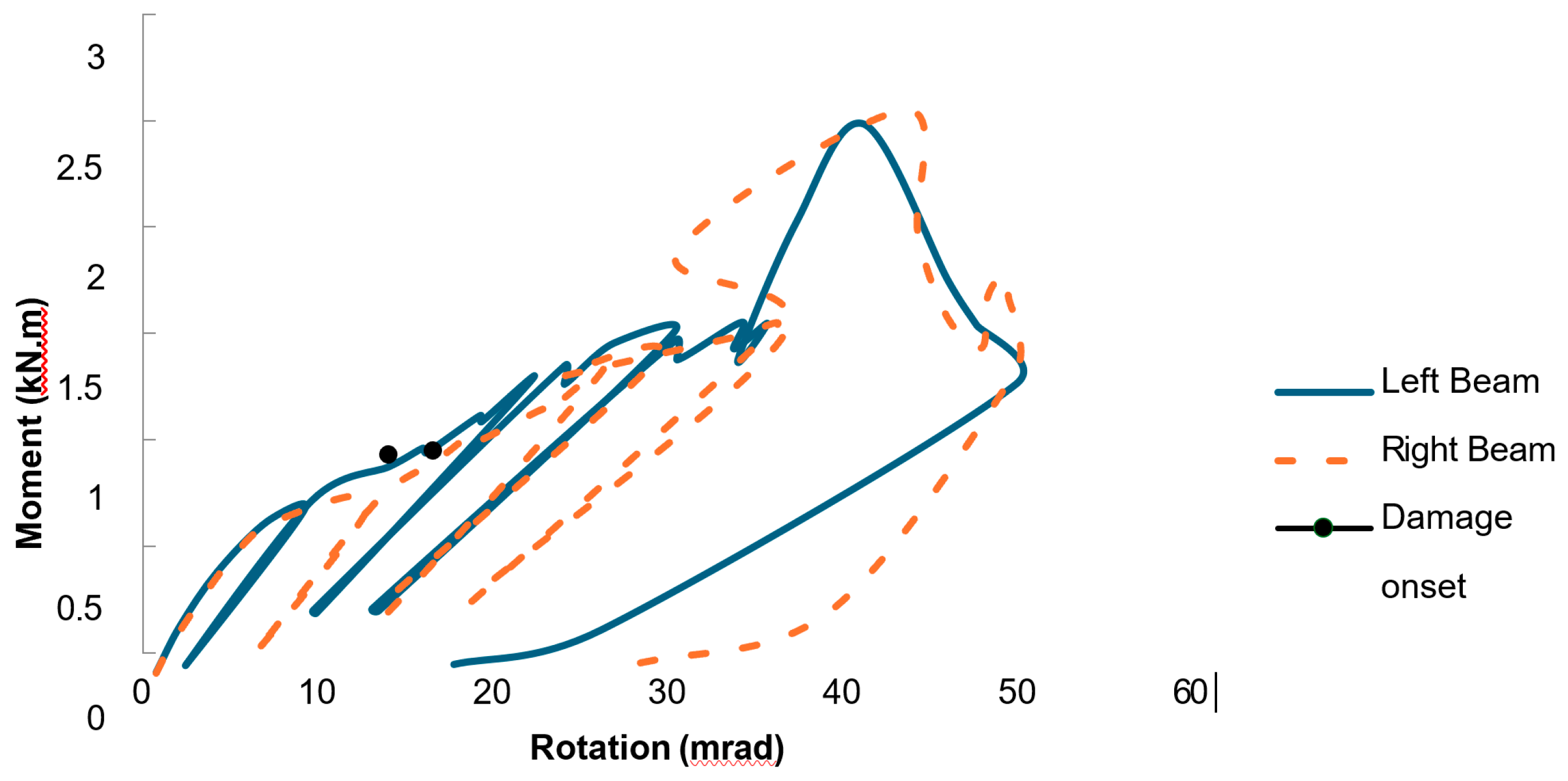
Figure 13.
Moment-rotation behaviour for the model Wmj254_3M18_BS
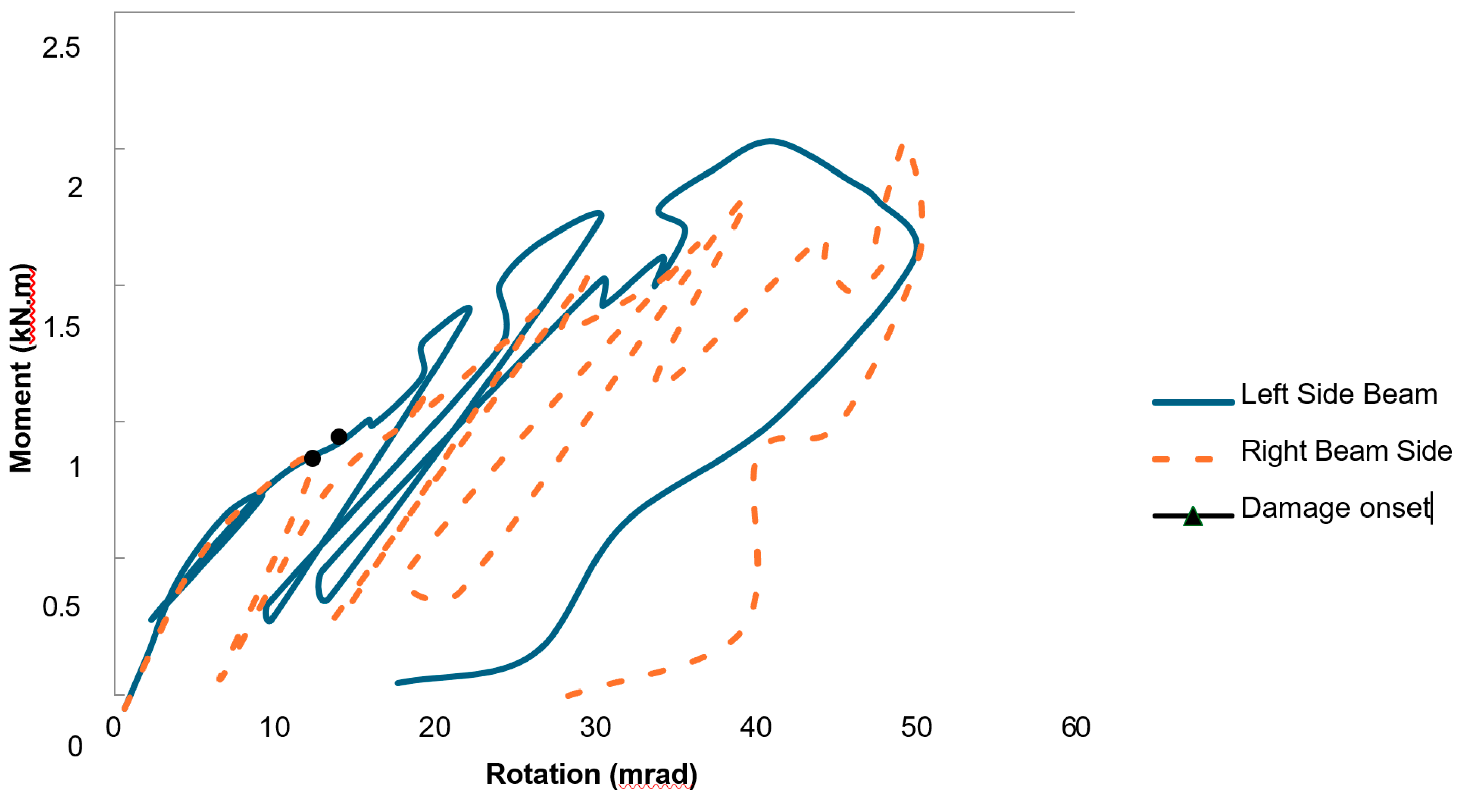
Figure 14.
Moment-rotation behaviour for the model Wmj254_3M16_BC2.0
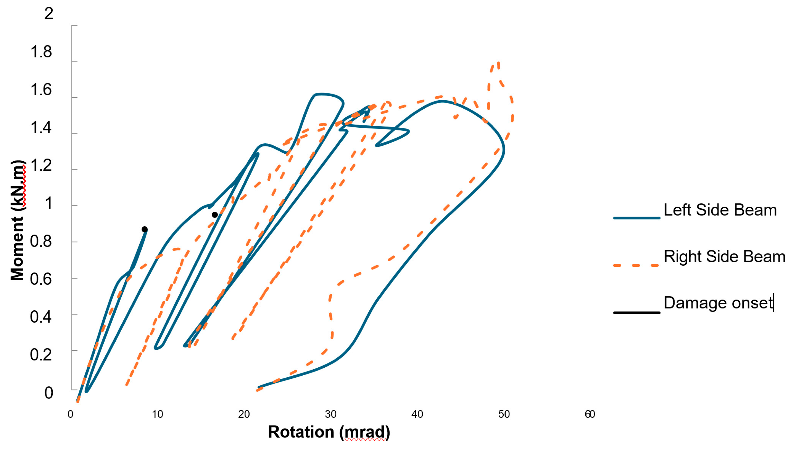

Table 1.
Elastic material properties for FRP profiles and cleats from Creative Composites [22].
Table 1.
Elastic material properties for FRP profiles and cleats from Creative Composites [22].
| Material Property | Input value |
| Density (tonne/mm3) | 2.1 × 10⁻⁹ |
| Young’s Modulus, E1 (N/mm2) | 29000 |
| Young’s Modulus, E2= E3 (N/mm2) | 8600 |
| Poisson’s Ratio, ν12 = ν13 | 0.35 |
| Poisson’s Ratio, ν23 | 0.12 |
| Shear Modulus, G12 = G13 (N/mm2) | 3000 |
| Shear Modulus, G23 (N/mm2) | 3400 |
Table 2.
Hashin damage for FRP beam and column flange from Creative Composites [22].
Table 2.
Hashin damage for FRP beam and column flange from Creative Composites [22].
| Material Property | Input value |
| Longitudinal Tensile Strength (N/mm2) | 275 |
| Longitudinal Compressive Strength (N/mm2) | 315.7 |
| Transverse Tensile Strength (N/mm2) | 95 |
| Transverse Compressive Strength (N/mm2) | 122.4 |
| Longitudinal Shear Strength (N/mm2) | 60 |
| Transverse Shear Strength (N/mm2) | 27.5 |
Table 3.
Hashin damage for FRP beam and column web from Creative Composites [22].
Table 3.
Hashin damage for FRP beam and column web from Creative Composites [22].
| Material Property | Input value |
| Longitudinal Tensile Strength (N/mm2) | 208.3 |
| Longitudinal Compressive Strength (N/mm2) | 257.8 |
| Transverse Tensile Strength (N/mm2) | 72.2 |
| Transverse Compressive Strength (N/mm2) | 97.6 |
| Longitudinal Shear Strength (N/mm2) | 48.3 |
| Transverse Shear Strength (N/mm2) | 23.4 |
Table 4.
Hashin damage for FRP leg angles (web cleats) from Creative Composites [22].
Table 4.
Hashin damage for FRP leg angles (web cleats) from Creative Composites [22].
| Material Property | Input value |
| Longitudinal Tensile Strength (N/mm2) | 215 |
| Longitudinal Compressive Strength (N/mm2) | 270 |
| Transverse Tensile Strength (N/mm2) | 115 |
| Transverse Compressive Strength (N/mm2) | 175 |
| Longitudinal Shear Strength (N/mm2) (Full section) | 48.3 |
| Longitudinal Shear Strength (N/mm2) (through heel of angle) | 23.4 |
| Transverse Shear Strength (N/mm2) | 23.4 |
Table 5.
Steel Grade 355 for loading plates plastic material properties [23].
Table 5.
Steel Grade 355 for loading plates plastic material properties [23].
| Yield Stress (N/mm2) | Plastic strain |
| 355 | 0 |
| 470 | 0.2 |
Table 6.
Steel Bolt Grade 8.8 plastic material properties [23].
Table 6.
Steel Bolt Grade 8.8 plastic material properties [23].
| Yiled Stress (N/mm2) | Plastic strain |
| 640 | 0 |
| 800 | 0.178 |
Table 7.
Joint Properties for Wmj254_3M16_WC150 beam-to-column joint configuration.
|
Specimen label (1) |
Mi (kN m) (2) |
φi (mrad) (3) |
Si = Mi/φi (kN m/rad) (4) |
Mj (kN m) (5) |
φj (mrad) (6) |
Sj = Mj/φj (kN m/rad) (7) |
Mmax (kN m) (8) |
φmax (mrad) (9) |
| Wmj254_3M16_WC150 (Left) | 0.75 | 7 | 107 | 0.93 | 13.3 | 70 | 2.45 | 40.4 |
| Wmj254_3M16_WC150 (Right) | 0.71 | 6.9 | 103 | 0.96 | 15.8 | 61 | 2.51 | 42.8 |
| Mean of 2 | 0.73 | 6.95 | 105 | 0.95 | 14.5 | 66 | 2.48 | 41.6 |
| CV | 3.8% | 1% | 2.7% | 2.4% | 12% | 9.7% | 1.7% | 4% |
Table 8.
Joint Properties for Wmj254_3M18_BS Beam-to-column joint configuration .
|
Specimen label (1) |
Mi (kN m) (2) |
φi (mrad) (3) |
Si = Mi/φi (kN m/rad) (4) |
Mj (kN m) (5) |
φj (mrad) (6) |
Sj = Mj/φj (kN m/rad) (7) |
Mmax (kN m) (8) |
φmax (mrad) (9) |
| Wmj254_3M18_BS (Left) | 0.75 | 7.2 | 104 | 0.95 | 13.4 | 71 | 2.03 | 40.4 |
| Wmj254_3M18_BS (Right) | 0.7 | 7 | 100 | 0.87 | 11.70 | 74 | 2.04 | 48.7 |
| Mean of 2 | 0.725 | 7.1 | 102 | 0.91 | 12.5 | 72.5 | 2.035 | 44.5 |
| CV | 4.9% | 2% | 2.8% | 6.2% | 9.6% | 6.9% | 0.3% | 13.1% |
Table 9.
Joint Properties for Wmj254_3M16_BC Beam-to-column joint configuration .
|
Specimen label (1) |
Mi (kN m) (2) |
φi (mrad) (3) |
Si = Mi/φi (kN m/rad) (4) |
Mj (kN m) (5) |
φj (mrad) (6) |
Sj = Mj/φj (kN m/rad) (7) |
Mmax (kN m) (8) |
φmax (mrad) (9) |
| Wmj254_3M16_BHC (Left) | 0.8 | 7.2 | 111 | 0.94 | 13.81 | 68 | 1.61 | 27.3 |
| Wmj254_3M18_BHC (Right) | 0.76 | 8.1 | 94 | 0.96 | 15.87 | 60.5 | 1.81 | 48.4 |
| Mean of 2 | 0.78 | 7.65 | 102.5 | 0.95 | 14.84 | 64.25 | 1.71 | 37.85 |
| CV | 3.6% | 8.3% | 12% | 1.5% | 9.7% | 8% | 8% | 39% |
Disclaimer/Publisher’s Note: The statements, opinions and data contained in all publications are solely those of the individual author(s) and contributor(s) and not of MDPI and/or the editor(s). MDPI and/or the editor(s) disclaim responsibility for any injury to people or property resulting from any ideas, methods, instructions or products referred to in the content. |
© 2025 by the authors. Licensee MDPI, Basel, Switzerland. This article is an open access article distributed under the terms and conditions of the Creative Commons Attribution (CC BY) license (http://creativecommons.org/licenses/by/4.0/).
Copyright: This open access article is published under a Creative Commons CC BY 4.0 license, which permit the free download, distribution, and reuse, provided that the author and preprint are cited in any reuse.


