

Submitted:
18 September 2024
Posted:
18 September 2024
You are already at the latest version
Abstract
This paper presents a numerical study of topology-optimised pin-end aluminium alloy columns using finite element analysis (FEA). The FEA models integrate geometric imperfections and material nonlinearity, validated against experimental findings from existing literature. Furthermore, modern design methodologies including Eurocode 9, Direct Strength Method (DSM), and Continuous Strength Method (CSM) are employed to assess the maximum load capacity of such columns. Parametric investigations encompass diverse parameters such as varied cross-sections, column lengths, and global and local imperfections. By analysing a total of 288 FE models, incorporating 16 column cross-sections across two lengths with nine distinct imperfections, the study compares results with those derived from modern design methodologies. Thus, this research elucidates the behaviour of novel cross-sections and the application of contemporary design techniques in their analysis.
Keywords:
aluminium
; columns
; FE analysis
; topology optimisation
; DSM
; CSM
1. Introduction
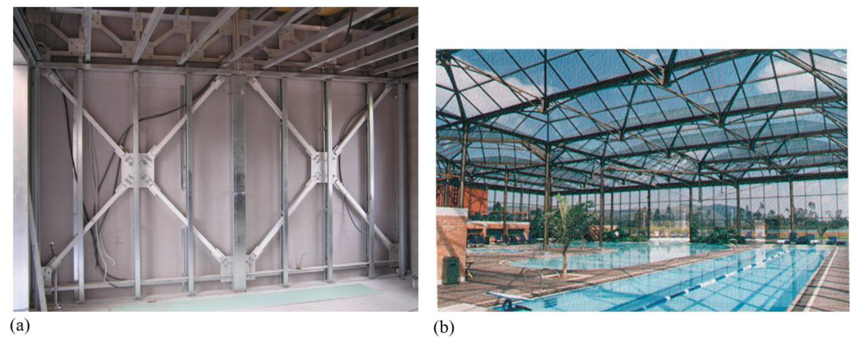
In recent years, the utilisation of aluminium columns in both civil and aerospace engineering has experienced significant growth, propelled by technological innovations and a steadfast commitment to sustainability, efficiency, and performance. This surge in usage underscores the inherent versatility and advantages offered by aluminium alloys, which have become indispensable in a wide array of structural applications. Aluminium, one of the most abundant elements on the earth, renowned for its corrosion resistance, favourable strength-to-weight ratio and similarities in design with stainless steel, has emerged as a preferred material choice in various industries (Georgantzia et al. 2021) [1]. Builders and developers are incorporating aluminium columns into green building projects to meet sustainability goals and reduce carbon footprints due to their light weight compared to steel (almost less than 2.5 times). Moreover, innovations in fabrication technologies, such as extrusion and 3D printing, have expanded the design possibilities for aluminium members in civil engineering applications compared to steel counterparts due to lower energy requirement for manufacturing. Complex geometries and custom profiles can be produced, allowing for more efficient structural designs and optimised material usage. Furthermore, in regions prone to seismic activity, aluminium columns are preferred for their ductility and ability to withstand dynamic loads. However, despite its numerous benefits, the inherent characteristics of aluminium alloys, such as lower stiffness compared to steel alloys, necessitate meticulous analysis and design considerations, particularly in structural applications where load-bearing capacity is paramount. One example would be the instability causing to lower the load-bearing capacity of aluminium columns under axial compressive loading.
Recently, numerous studies have explored compression members constructed from cold-formed steel (CFS), particularly those with perforations, generating a substantial amount of data to guide standards in the design of steel columns. Therefore, before delving into the available literature on aluminium columns, we present a brief overview of the literature concerning CFS columns. Shanmugam and Dhanalakshmi (2001) [2] examined the influence of web plate slenderness ratio and opening area ratio on the ultimate compressive strengths of perforated CFS channel stub columns. Moen and Schafer (2007) [3] found that the presence of slotted holes in CFS columns affected the post-peak response and ductility, influenced by the column's cross-section type and length. Yao and Rasmussen (2012) [4] explored the effects of perforations on inelastic stress distributions, load transfers, and failure modes of perforated simply supported plates and C-section columns. They observed distinct failure modes and stress distribution changes due to perforations. Kulatunga and Macdonald (2013) [5] investigated the influence of perforation positions, while Kulatunga et al. (2014) [6] studied the effect of perforation shapes on the ultimate compressive strengths of CFS columns with lipped channel cross-sections. Singh et al. experimentally studied the axial compressive capacity of CFS square hollow section (SHS) and rectangular hollow section (RHS) columns containing circular perforations, noting conservative but generally scattered predictions by existing design equations. Additionally, various studies investigated the compression behaviour of columns under geometrical imperfections using design methodologies such as the direct strength method (DSM) [8], continuous strength method (CSM) [9], and design codes such as Eurocode 3 (EC3) and Eurocode 9 (EC9).
Limited research has been conducted on the compressive capacity of aluminium columns, with most existing studies concentrating on SHS, RHS, and circular hollow sections (CHS). Zhu and Young [13,14,15] conducted finite element (FE) investigations on various aluminium alloy hollow sections (SHS, RHS, and CHS), both welded and non-welded, focusing on their axial compressive capacity. They developed tailored design equations for aluminium alloy tubes with transverse welds at column ends. Zhou and Young [16] also examined the effect of circular holes on the web crippling strength of aluminium alloy SHSs through experimental and numerical analyses. Mohandas et al. [17] explored the axial compressive capacity of SHS stub columns made from aluminium alloy, finding that those constructed from the 6061-T6 grade aluminium exhibit promising structural behaviour as a potential substitute for steel stub columns. Su et al. [18] conducted an experimental study on aluminium alloy SHS and RHS columns, to examine their cross-section capacity and to explore the potential leverage of strain hardening in design, with and without internal cross stiffeners. Later, Su et al [19] investigated the influence of strain hardening and moment redistribution on the compressive behaviour and design of aluminium alloy structures. Using the CSM, they analysed approximately 900 experimental and numerical results. Their findings indicate that CSM yields more accurate mean resistance predictions and reduces variability for both determinate and indeterminate aluminium alloy structures, in comparison to the Aluminum Design Manual [20], the Australian/New Zealand Standard [21], and Eurocode 9 [22]. Additionally, Feng et al. [23] and Feng and Liu [24] studied the flexural buckling performance of 6061-T6 and 6063-T5 normal-strength SHS and RHS columns with circular openings, comparing experimental and numerical findings with current standards. Furthermore, various column shapes, including RHS [25], SHS [26], CHS [27,28], angle-sections [29,30], I-sections [31-33] and others [34,35,36], were investigated. The analysis revealed that existing standards generally offered inaccurate predictions of resistance for columns failing due to flexural buckling, local buckling, torsional buckling, or combined buckling.
This study draws upon the pioneering work by Tsavdaridis et al. [37,38] that resulted a series of highly optimised cross-sections tailored for aluminium columns, with a prime objective of augmenting their performance. Given aluminium lower stiffness relative to steel, conventional structural elements may necessitate optimisation of their cross-sections to enhance structural efficacy. While certain aluminium alloys, like AL 6061-T6, boast yield and ultimate strength akin to or surpassing common structural steels, their inferior stiffness underscores the need for cross-sectional optimisation strategies.
Expanding upon the groundwork laid by Tsavdaridis et al. [37], who introduced 16 innovative aluminium section beam and column profiles, this study advances the investigation. Marinopoulou et al. [38] utilised finite element analysis (FEA) with ABAQUS software to determine the ultimate compressive resistance values for stub columns, aligning FEA outcomes with those derived from CSM, DSM, and EC9 methodologies. With a focus on pin-ended columns featuring topology-optimised cross sections, this research builds upon the modeling approach outlined in Georgantzia et al.'s [39] study, which explored the compressive behaviour of C-section aluminium columns. This study extends its scope to encompass stub and pin-end columns, with the FEA model of pin-ended aluminium columns validated against Georgantzia et al.'s findings. Following experiment validation, a parametric inquiry delves into both standard and novel cross sections, assessing the efficacy of modern design techniques. This extensive investigation spans 16 diverse cross sections across two column lengths, subjecting each to varying global and local imperfections in FEM simulations, totaling 288 distinct FEA models to determine the maximum load capacity of these columns.
The structure of the paper is as follows: Section 2 outlines the validation of the FEA model against the experiments conducted by [39]. Section 3 details the FEA models and the subsequent parametric investigation. The findings and their discussion are presented in Section 4, followed by the conclusions in Section 5.
2. Validation of the FEA Model
Georgantzia et al. [39] conducted both experimental and numerical investigations on C-section columns made from 6082-T6 heat-treated aluminium alloy. In this paper, the FE models were validated against the experimental results as shown in Figure 2.
Columns inherently possess geometric imperfections due to manufacturing processes and other external factors. aluminium columns tend to be more imperfect than the steel columns due to its nature. Aluminium has smaller elastic modulus, and it deforms easily. It triggers higher imperfection values for aluminium columns after its production, especially for the thin sections. Moreover, aluminium alloys are more ductile than the steel and alloys, the plastic deformations occurred during the manufacturing along with the thin sections. To incorporate these imperfections into the FEA, a two-step approach is adopted, comprising eigenvalue buckling analysis in advance of the nonlinear static analysis. The eigenvalue buckling analysis is employed to determine the imperfect shapes of the columns, which are subsequently factored and integrated before utilised as the initial conditions for the nonlinear static analysis.
The FEA model incorporates two types of geometric imperfections: global and local imperfections. Initial conditions for the static analysis are determined using the first global and local eigen buckling modes, which are then adjusted using imperfection factors. These factors are dependent on column dimensions such as effective length, wall thickness, and flange thickness. Specifically, the global imperfection factor is set at , where represents the column length, while the local imperfection factor is defined as , with representing the flange thickness of the column cross-section. Similar parameter values as those used in [39] were employed here as they encompass typical configurations of aluminium columns.
The aluminium C-section column is represented using shell elements, depicted in Figure 3. Utilising shell elements is a widely adopted practice for thin-walled columns, as demonstrated in the literature [8,10,12,39]. S4R element from the ABAQUS element library was employed. To simulate the pin-ended column test accurately, one of the rotational degrees of freedom is left unconstrained. This is achieved using KINEMATIC COUPLING constraints via the RBE2 element, as illustrated in Figure 4, since both ends of the column are pin-ended. Specifically, the UX and ROTY degrees of freedom (DOF) are set free based on the column's orientation during the column test.
Mesh convergence studies were conducted to optimise computational efficiency. A column with a square hollow section measuring 100 mm × 100 mm × 5 mm and extending 1 m in length was modeled using four different mesh sizes ranging from 2 mm to 5 mm. After comparing the results, it was found that the buckling load value varied within approximately ±1%. Consequently, a mesh size of 5 mm was selected for all simulations to improve computational efficiency. Considering the substantial number of simulation cases—totalling 288—that must be addressed, computational efficiency is a crucial aspect of this study.
In the validation studies, a multilinear hardening material model was adopted. However, for the subsequent parametric studies, a bilinear hardening model was employed due to the limited tangent modulus of AL6063-T6. The material properties required to establish the bilinear hardening model were sourced from EC9 [22].
The comparison between the maximum load and mid-height deflection results of the validation study is depicted in Figure 5, showing an exceptional alignment between the outcomes. Specifically, Table 1 provides a detailed comparison of the ultimate load between the findings of [39] and those derived from the present investigation.
3. Modern Design Methodologies for Assessing Buckling Loads
Modern design methods are empirically derived and standardised approaches used by engineers in their design processes. In both validation and parametric studies, methods such as the Direct Strength Method (DSM), Continuous Strength Method (CSM), and EC9 were utilised. Although these methods are traditionally designed for standard cross sections like square hollow sections and circular hollow sections, this study emphasizes their application to novel cross sections rather than conventional ones. A brief overview of these methods is provided herein.
3.1. Direct Strength Method (DSM)
Schafer and Peköz [42] pioneered the DSM for cold-formed steel structures, leveraging data from concentrically loaded pin-ended cold-formed steel columns [43,44]. Subsequently, Zhu and Young [27,45,46,47] adapted DSM, with certain adjustments, for designing aluminium alloy SHS and RHS columns. This approach initially computes the non-dimensional slenderness for flexural buckling, denoted as using the following formula:
where, represents the Euler critical elastic buckling load and signifies the yield load:
Next, the nominal axial load for flexural buckling, is calculated from:
Furthermore, , represents the limit state load for the cross-section, which can be calculated using the following formula [48]:
The non-dimensional slenderness for the interaction of local and flexural buckling, denoted as , is then calculated using:
Using the value of , the nominal axial strength for local buckling, can be calculated from:
Finally, DSM limit load can be found from the minimum of given in Eqs. (4) and (7).
3.2. Continuous Strength Method (CSM)
Originally designed for stainless steel and carbon steel materials, CSM is a deformation-based design framework that incorporates the advantageous effects of strain hardening. A series of studies in the literature [49,50,51,52,53] have been undertaken to develop and refine the CSM for CFS structures. Su et al. [54] modified this approach to be used for aluminium alloy structural elements.
The approach emphasizes the deformation capacity of the cross-section, deriving it from a material curve that incorporates both linear and nonlinear components. Unlike DSM and Eurocode, the CSM evaluates strain rather than stress, distinguishing its methodology. In this method first critical buckling stress, is calculated using the following:
Then, cross-sectional slenderness, is calculated
For stocky and slender ,cross sections CSM strain, can be found from the following relation:
Thus, the limit stress can be calculated from:
where is the tangent modulus of the nonlinear part of the stress-strain curve and is the yield strain.
3.3. Eurocode 9 (EC9)
According to EC9, material buckling class for 6063-T6 aluminium material is “Class A”. The limit buckling load is given as:
where
and is the yield stress. Note that, for material class A, and . The slenderness is defined as
where is the elastic critical force for the relevant buckling mode based on the gross cross-sectional properties.
3.4. Comparison of FEA Results with Those of the Design Codes
Maximum load calculated using the aluminium column FEA model simulated with ABAQUS FE Static RIKS Solver has been compared with all three methods explained above. The results summary is presented in Table 2.
4. Parametric Study
In the parametric investigation, the novel cross-sections examined by Marinopoulou et al. [15] were utilised with slight adjustments. Square hollow sections (SHS) featuring both inner and outer fillets have been included, as they offer better manufacturability compared to profiles without radii or with radii only on the inner or outer edges. The incorporation of corner radii enhances the effectiveness of extrusion manufacturing processes. Imperfection parameters are sourced from Georgantzia et al. [39], and the various types of cross-sections are illustrated in Figure 6 and Figure 7. Detailed cross-sectional dimensions are provided in Table 3.
Table 4 presents the comprehensive conditions encompassing cross-section types, imperfection specifications, and column lengths considered in this study. Each cross-section variant is tested across both column lengths. Also, for each length, three of the global imperfections have been applied to columns. For each global imperfection value, three of the local imperfections have been combined for the study. Subsequently, all specified local imperfection values are individually applied to each setup. Global imperfection values are determined based on the effective length of the column, while local imperfection values are calculated using the flange thickness.
For considering imperfections, the same approach as in the validation study earlier, is followed. To ensure mesh convergence, column A1 is simulated with four different mesh sizes ranging from 2 mm to 5 mm. Upon comparison, the buckling load values exhibit a variation of approximately ±1%. Consequently, to optimise computational efficiency, a mesh size of 5 mm is selected for all simulations. Given the substantial number of simulation cases computational efficiency is a paramount concern in this study.
A bilinear plasticity material model was adopted, as it is well-suited for this analysis due to the material's minimal tangent modulus. The model employs a 5 mm free mesh utilising S4R elements in ABAQUS. Boundary conditions are applied from both ends of the column, with a center node coupled using KINEMATIC COUPLING.
5. Results and Discussion
A set of 288 finite element models were carried out to assess the impact of imperfection values. Across all cases, there exists an average deviation of 3% between the lowest and highest imperfection values, with a maximum deviation of 5.4%. Given that the first global mode has been applied as the global imperfection factor, resulting in columns exhibiting a half-sine wave shape upon buckling. Notably, the alteration of local factors yields a minimal impact on the results, with variations less than 1% observed across all models.
Figure 9 portrays the behaviour exhibited by the columns, demonstrating a global buckling pattern with observable deformations on the walls and flanges induced by local imperfections. This underscores the predominant influence of global imperfections on the failure behaviour, attributed to the manufacturing process. In instances where columns have shorter lengths, the behaviour aligns with the first mode of global imperfection, leading to failure primarily at the walls and/or flanges. Conversely, longer columns exhibit a half-sine deflection along their length, indicative of Euler failure mode dependence.
In the comparative analysis, the finite element results for each column are averaged across all imperfection scenarios. Table 5 provides a comparison between the results obtained from FE modeling and calculations based on EC9. It is observed that the disparity between FEM and EC9 calculations increase with the slenderness value, with EC9 values consistently surpassing FEM results.
Table 6 presents the results of Direct Strength Method (DSM) alongside their comparison with FEM results. Across all cases, FEM results are higher than those obtained from DSM, albeit with less sensitivity to slenderness compared to EC9.
Table 7 offers a comparison between FEM results and those derived from Continuous Strength Method (CSM). Notably, this comparison yields lower error values, with FEM results generally exceeding those of CSM. However, this trend shifts within certain slenderness ratios (0.32 - 0.43).
Figure 11 and Figure 12 present the comparison results based on slenderness values outlined in the preceding section. The DSM exhibits precision for slenderness values below 0.4, while EC9 yields satisfactory results for slenderness values exceeding 0.22. The CSM generally outperforms other methods, consistent with findings in the literature. Notably, the CSM results exhibit the lowest coefficient of variation (COV), indicating superior precision. By directly calculating cross-sectional strength with plasticity correction, CSM offers adequate results without requiring significant modifications.
Figure 12 provides the precision of methods with respect to slenderness values. As it is mentioned before, CSM methods works perfectly within all slenderness values. EC9 works relatively better between the slenderness values 0.4-0.43, however it may need some improvement especially the other slenderness values. On the other hand, DSM works relatively better between the slenderness values 0.2-0.215 but it also needs some improvement. At the other slenderness values, it has divergent characteristics.
The nonlinear relationship between maximum load and slenderness values primarily stems from variations in cross-sectional inertia across different slenderness values. Since slenderness values encompass three distinct geometries, each with varying inertia-to-cross-sectional area ratios, this variability contributes to the observed nonlinearity in results. Additionally, differences in local imperfection modes across various cross-sectional types, influence both maximum load and column failure mode.
6. Concluding Remarks
This paper presents a numerical investigation on novel aluminium alloy sections using finite element analysis (FEA). The FEA models incorporate geometric imperfections and material nonlinearity, with validation against experimental results from the literature. An extensive parametric analysis was conducted on 288 models featuring different cross-sections, column lengths, global, and local imperfections. The FEA results were compared with modern design approaches such as Eurocode 9, the Direct Strength Method, and the Continuous Strength Method. From the results of this study, the following conclusions can be drawn:
- The newly designed columns, in comparison to regular cross-sections, demonstrate outstanding performance with minimal mass increase.
- Utilising regular columns necessitates larger cross-sections or additional compressive members in the structure, whereas the novel sections offer superior mass-to-ultimate-load performance.
- Findings indicate an average 3% deviation between the lowest and highest imperfection values, with a maximum deviation of 5.4%.
- Local imperfection variations had minimal impact, with deviations less than 1% across all models.
- Shorter columns predominantly fail at the walls and/or flanges, aligning with the first mode of global imperfection, while longer columns exhibit a half-sine deflection along their length, indicative of Euler failure mode dependence.
- EC9 calculations consistently outperform FEM results, particularly with increasing slenderness values.
- Continuous Strength Method CSM exhibited the smallest errors and higher precision, directly calculating cross-sectional strength with plasticity correction.
- The observed nonlinear relationship between maximum load and slenderness values stemmed from variations in cross-sectional inertia and differences in local imperfection modes across various cross-sectional types.
References
- Georgantzia, E., Gkantou, M., & Kamaris (2021) Aluminum alloys as structural material: A review of research. Engineering Structures. [CrossRef]
- Shanmugam, N. E., & Dhanalakshmi, M. (2001). Design for openings in cold-formed steel channel stub columns. Thin-Walled Structures, 39(12), 961–981. [CrossRef]
- Moen, C. D., & Schafer, B. W. (2008). Experiments on cold-formed steel columns with holes. Thin-Walled Structures, 46(10), 1164–1182. [CrossRef]
- Yao, Z., & Rasmussen, K. J. R. (2012). Inelastic local buckling behaviour of perforated plates and sections under compression. Thin-Walled Structures, 61(6), 49–70. [CrossRef]
- Kulatunga, M. P., & Macdonald, M. (2013). Investigation of cold-formed steel structural members with perforations of different arrangements subjected to compression loading. Thin-Walled Structures, 67, 78–87. [CrossRef]
- Kulatunga, M. P., Macdonald, M., Rhodes, J., & Harrison, D. K. (2014). Load capacity of cold-formed column members of lipped channel cross-section with perforations subjected to compression loading—Part I: FE simulation and test results. Thin-Walled Structures, 80, 1–12. [CrossRef]
- Singh, T.G., & Singh, K.D. (2018). Experimental investigation on performance of perforated cold-formed steel tubular stub columns. Thin-Walled Structures, 131, 107–121. [CrossRef]
- Dong, D., Fan, S., Liu, M., Zhu, T. (2023). Calculation method for local–global interaction buckling capacity of stainless steel C-columns - Structures, 2023. [CrossRef]
- Yun, X., Meng, X., & Gardner, L. (2022). Design of cold-formed steel SHS and RHS beam–columns considering the influence of steel grade. Thin-Walled Structures, 171, 108600. [CrossRef]
- Ma, Jia-Lin, Tak-Ming Chan, and Ben Young. "Cold-formed high strength steel tubular beam-columns." Engineering Structures 230 (2021): 111618. [CrossRef]
- Chen, Man-Tai, and Ben Young. "Material properties and structural behavior of coldformed steel elliptical hollow section stub columns." Thin-Walled Structures 134 (2019): 111-126. [CrossRef]
- Yun, Xiang, and Leroy Gardner. "The continuous strength method for the design of cold-formed steel non-slender tubular cross-sections." Engineering Structures 175 (2018): 549-564. [CrossRef]
- Zhu, J. H., & Young, B. (2006). Aluminum alloy tubular columns − Part I: finite element modeling and test verification. Thin-Walled Structures, 44(8), 961–968. [CrossRef]
- Zhu, J. H., & Young, B. (2006). Aluminum alloy tubular columns − Part II: parametric study and design using direct strength method. Thin-Walled Structures, 44(8), 969–985. [CrossRef]
- Zhu, J. H., & Young, B. (2008). Numerical investigation and design of aluminum alloy circular hollow section columns. Thin-Walled Structures, 46(12), 1437–1449. [CrossRef]
- Zhou, F., & Young, B. (2010). Web crippling of aluminum tubes with perforated webs. Engineering Structures, 32(5), 1397–1410. [CrossRef]
- Mohandas, M., Joseph, B. M., & Sabu, N. V. (2016). Numerical investigation on aluminum alloy stub columns with openings. International Journal of Innovative Research in Science, Engineering and Technology, 5(8), 14944–14950. [CrossRef]
- Su, M.N., & Young, B. (2014). Testing and design of aluminum alloy cross-sections in compression. Journal of Structural Engineering, 140(9), 04014047. [CrossRef]
- Su, Mei-Ni, Ben Young, and Leroy Gardner. "The continuous strength method for the design of aluminum alloy structural elements." Engineering Structures 122 (2016): 338-348. [CrossRef]
- Aluminum Association (AA). Aluminum design manual. Washington, DC, US; 2010.
- Australian/New Zealand Standard (AS/NZS). Aluminum structures part 1: Limit state design. AS/NZS 1664.1:1997, Sydney, Australia; 1997.
- European Committee for Standardization (EC9). Eurocode 9: design of aluminium structures—part 1-1: general rules—general rules and rules for buildings. BS EN 1999-1-1:2007, CEN; 2007.
- Feng, R., Zhu, W., Wan, H.Y., Chen, A.Y., & Chen, Y. (2018). Tests of perforated aluminum alloy SHSs and RHSs under axial compression. Thin-Walled Structures, 130, 194–212. [CrossRef]
- Feng, R., & Liu, J.R. (2019). Numerical investigation and design of perforated aluminum alloy SHS and RHS columns. Engineering Structures, 199, 109591. [CrossRef]
- Hu, Yaowei, et al. "Study of buckling behavior for 7A04-T6 aluminum alloy rectangular hollow columns." Thin-Walled Structures 169 (2021): 108410. [CrossRef]
- Li, Beibei, et al. "Flexural buckling of extruded high-strength aluminum alloy SHS columns." Thin-Walled Structures 179 (2022): 109717. [CrossRef]
- Zhu, J.H., & Young, B. (2008). Numerical investigation and design of aluminum alloy circular hollow section columns. Thin-Walled Structures, 46, 1437–1449. [CrossRef]
- Feng, R., Mou, X.L., Chen, Z.M., Roy, K., & Chen, B.S. (2020). Finite-element modeling and design guidelines for axial compressive capacity of aluminum alloy circular hollow sections with holes. Thin-Walled Structures, 157, 107027. [CrossRef]
- Zhang, Y., Wang, Y.Q., Wang, Z.X., Bu, Y.D., & Fan, S.G. (2020). Experimental investigation and numerical analysis of pin-ended extruded aluminum alloy unequal angle columns. Engineering Structures, 215, 110694. [CrossRef]
- Zhang, Y., Bu, Y.D., Wang, Y.Q., Wang, Z.X., Ouyang, Y.W., (2021). Study of flexural–torsional buckling behavior of 6061-T6 aluminum alloy unequal-leg angle columns. Thin-Walled Structures, 164, 107821. [CrossRef]
- Adeoti, G.O., Fan, F., Wang, Y.J., & Zhai, X.M. (2015). Stability of 6082-T6 aluminum alloy columns with H-section and rectangular hollow sections. Thin-Walled Structures, 89, 1–16. [CrossRef]
- Wang, Y.Q., Yuan, H.X., Chang, T., Du, X.X., & Yu, M. (2017). Compressive buckling strength of extruded aluminum alloy I-section columns with fixed-pinned end conditions. Thin-Walled Structures, 119, 396–403. [CrossRef]
- Yan, Jia-Bao, et al. "Compression behaviours of aluminum alloy I-column at low temperatures." Structures. Vol. 44. Elsevier, 2022. [CrossRef]
- Zhu, J.H., Li, Z.Q., Su, M.N., & Young, B. (2019). Behavior of aluminum alloy plain and lipped channel columns. Thin-Walled Structures, 135, 306–316. [CrossRef]
- Roy, K., Chen, B.S., Fang, Z.Y., Uzzaman, A., Chen, X., & Lim, J.B.P. (2021). Local and distortional buckling behavior of back-to-back built-up aluminum alloy channel section columns. Thin-Walled Structures, 163, 107713. [CrossRef]
- Chang, Y.C., Liu, M., Wang, P.J., & Li, X.L. (2017). Behaviors and design method for distortional buckling of thin-walled irregular-shaped aluminum alloy struts under axial compression. Engineering Structures, 153, 118–135. [CrossRef]
- Tsavdaridis, K. D., Efthymiou, E., Adugu, A., Hughes, J. A., & Grekavicius, L. (2019). Application of structural topology optimisation in aluminum cross-sectional design. Thin-Walled Structures, 139, 372-388. [CrossRef]
- Marinopoulou, E., Tsavdaridis, K. D., & Efthymiou, E. (2022). Modern Design Methods on Optimised Novel Aluminum Profiles. Buildings, 12(11), 1904. [CrossRef]
- Georgantzia, E., Gkantou, M., & Kamaris, G. S. (2023). Aluminum alloy channel columns: Testing, numerical modelling and design. Thin-Walled Structures, 182, 110242. [CrossRef]
- Spyrakos, C. C., & Ermopoulos, J. (2005). Development of aluminum load-carrying space frame for building structures. Engineering structures, 27(13), 1942-1950.4. [CrossRef]
- Valencia, G. (2001). Recent aluminum roof structures in Colombia. In Structures 2001: A Structural Engineering Odyssey (pp. 1-9).
- Schafer BW, Peköz T. Direct strength prediction of cold-formed steel members using numerical elastic buckling solutions. In: Proceeding of 14th international specialty conference on cold-formed steel structures. University of Missouri-Rolla, Rolla, MO, 1998. p. 69–76.
- Schafer BW. Distortional buckling of cold-formed steel columns. August final report to the American Iron and Steel Institute, Washington, DC, 2000.
- Schafer BW. Local, distortional, and Euler buckling of thin-walled columns. J Struct Eng 2002;128(3):289–99. [CrossRef]
- Zhu, J.H.; Young, B. Tests and Design of Aluminium Alloy Compression Members. J. Struct. Eng. ASCE 2006, 132, 1096–1107. [CrossRef]
- Zhu JH, Young B. Aluminum alloy tubular columns—part I: finite element modeling and test verification. Thin-Walled Struct 2006;44(9):961–8. [CrossRef]
- Zhu JH, Young B. Aluminum alloy tubular columns—part II: parametric study and design using direct strength method. Thin-Walled Struct 2006;44(9):. [CrossRef]
- Gardner, L. Fieber, A. Macorini, L. Formulae for Calculating Elastic Local Buckling Stresses of Full Structural Cross-Sections. Structures 2019, 17, 2–20. [CrossRef]
- Gardner L. The continuous strength method. Proc ICE – Struct Build 2008;161 (3):127–33. [CrossRef]
- Gardner L, Wang F, Liew A. Influence of strain hardening on the behavior and design of steel structures. Int J Struct Stab Dyn 2011;11(5):855–75. [CrossRef]
- Afshan S, Gardner L. The continuous strength method for structural stainless steel design. Thin-Walled Struct 2013;68(2013): 42–49. [CrossRef]
- Buchanan C, Gardner L, Liew A. The continuous strength method for the design of circular hollow sections. J Constr Steel Res 2016;118:207–16. [CrossRef]
- Liew A, Gardner L. Ultimate capacity of structural steel cross-sections under compression bending and combined loading. Structures 2015;1:2–11. [CrossRef]
- Su, M. N., Young, B., & Gardner, L. (2016). The continuous strength method for the design of aluminium alloy structural elements. Engineering Structures, 122, 338-348. [CrossRef]
Figure 2.
Images of experiment setup and specimen conducted in [39]: (a) test specimen, (b) test setup.
Figure 2.
Images of experiment setup and specimen conducted in [39]: (a) test specimen, (b) test setup.
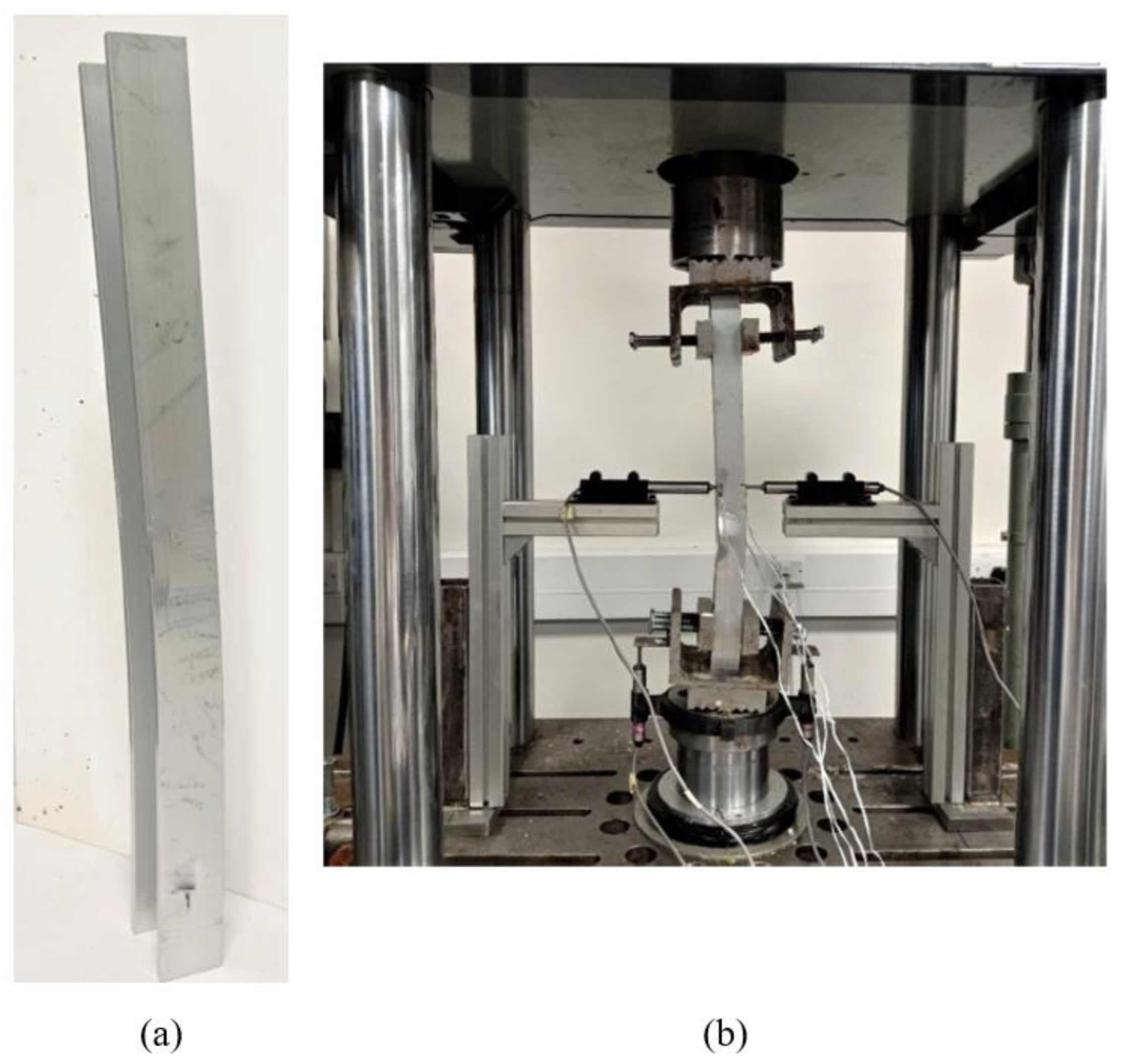
Figure 3.
Finite Element Analysis model of the validation model.
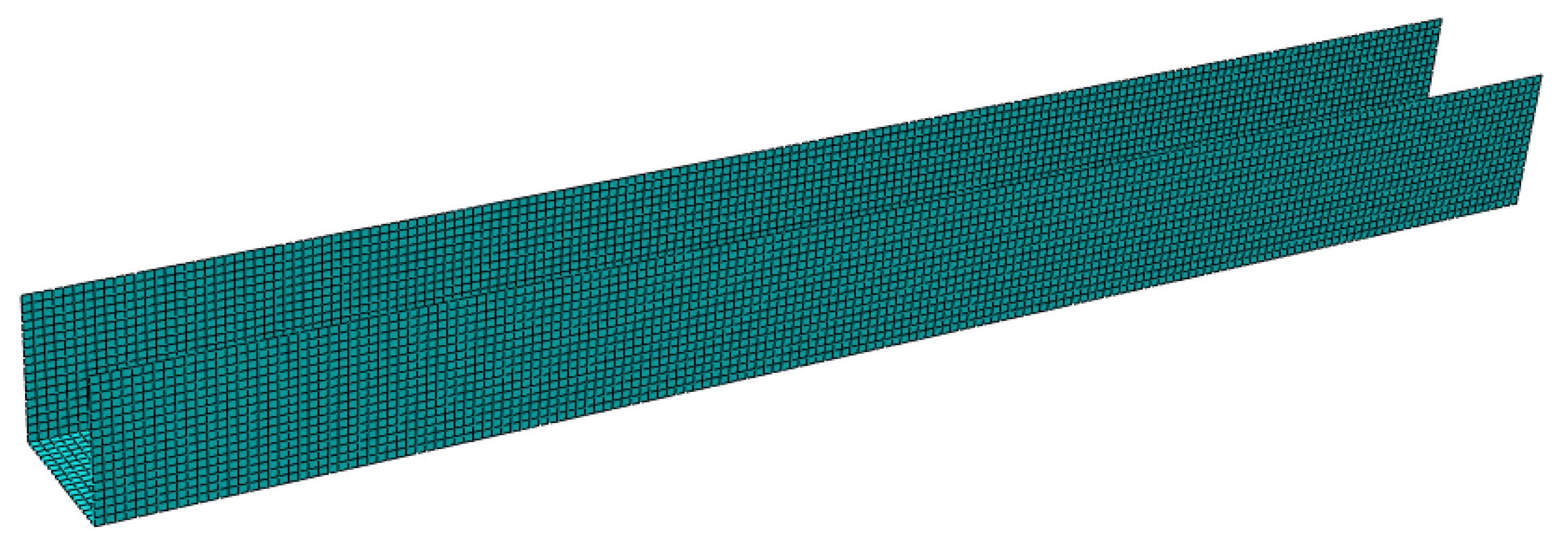
Figure 4.
Boundary conditions of the validation FEM Model.
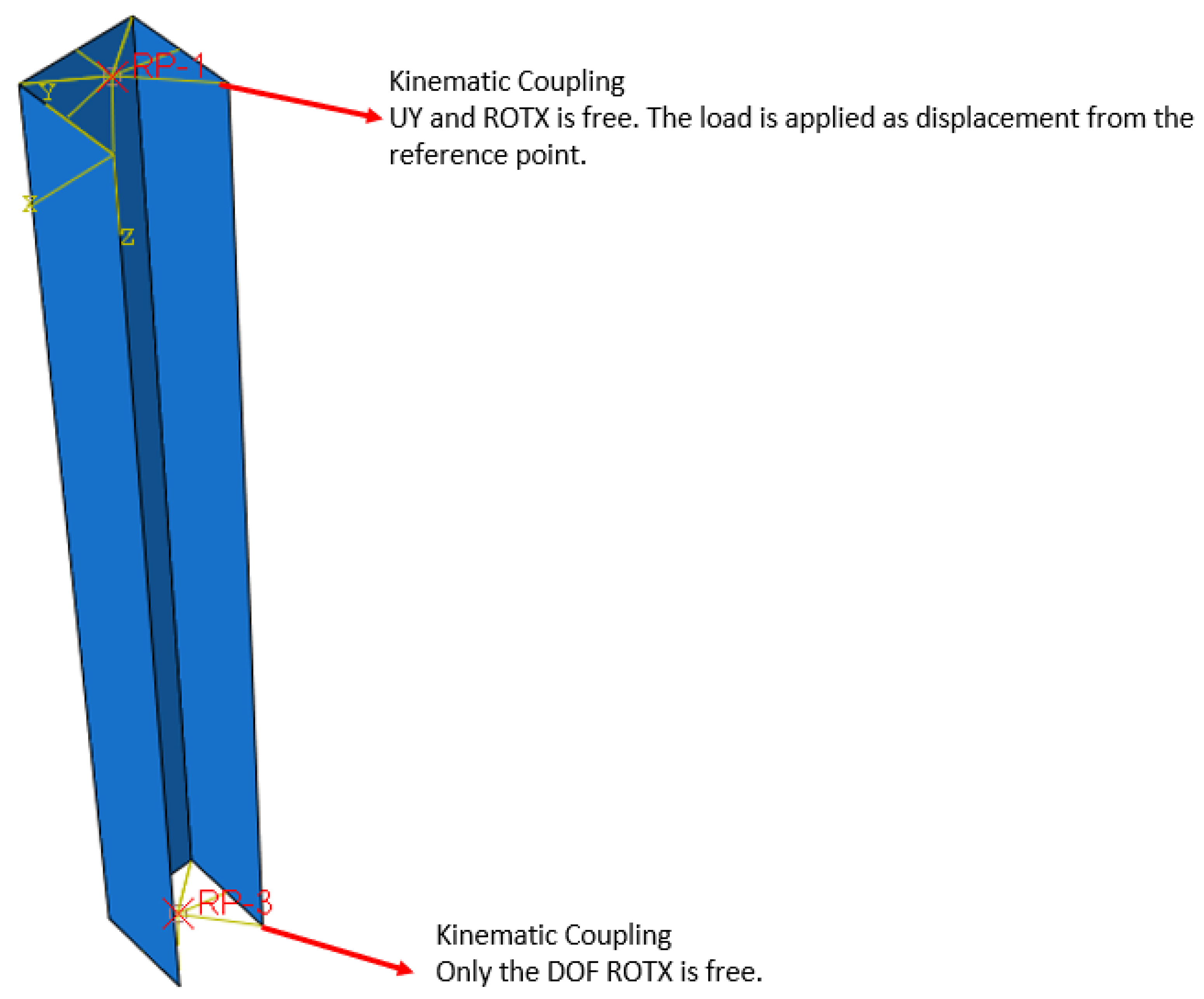
Figure 5.
Graph shows result comparison between the simulation results from Georgantzia et al. [39] and the FEA simulation.
Figure 5.
Graph shows result comparison between the simulation results from Georgantzia et al. [39] and the FEA simulation.
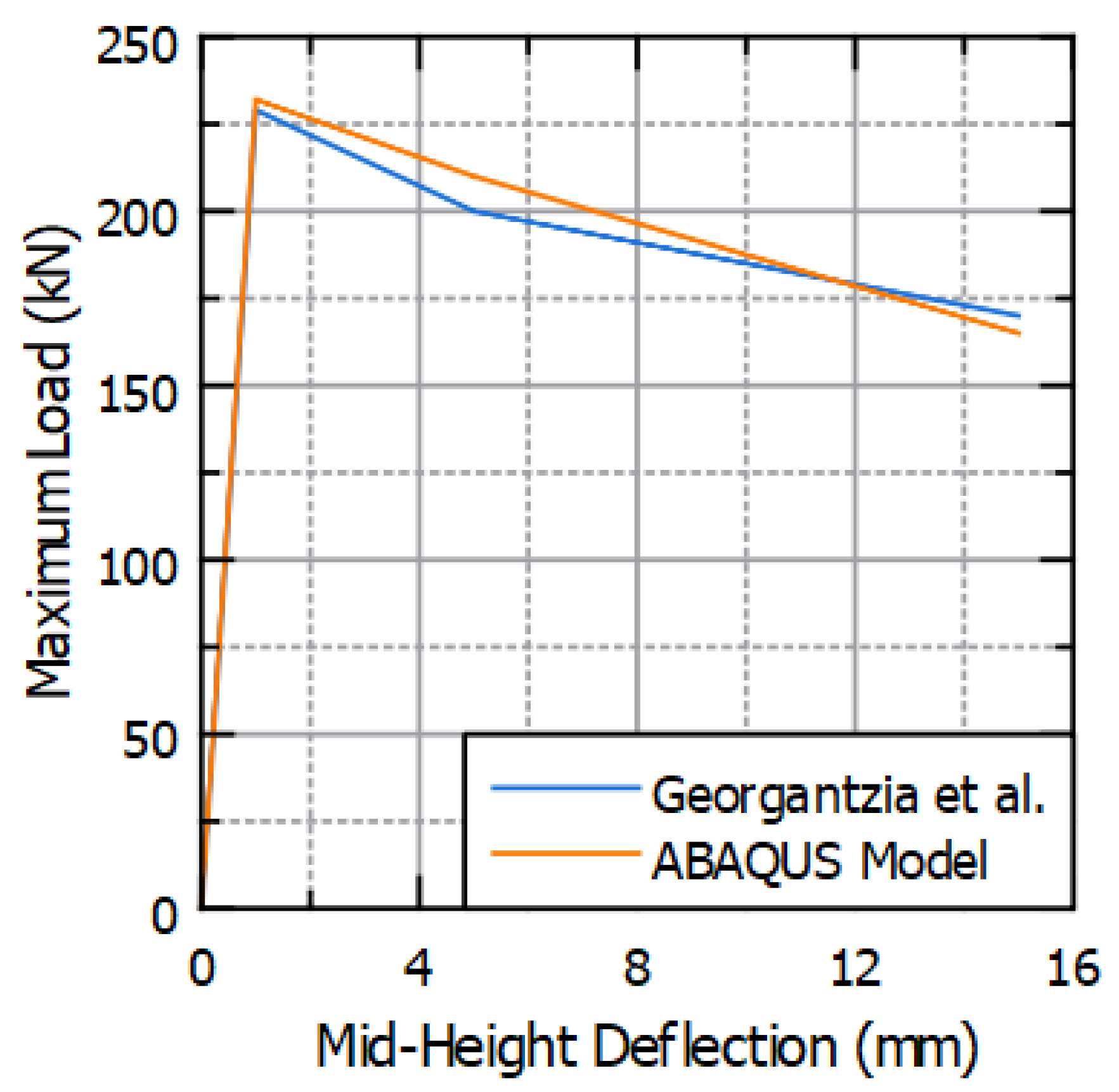
Figure 6.
The generic representation of square hollow sections used in analyses.
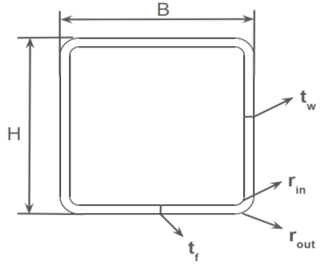
Figure 7.
Novel cross section geometries [15] the section codes N1-N6 have been assigned for these cross sections (a) N1, (b) N2, (c) N3, (d) N4, (e) N5, (f) N6).
Figure 7.
Novel cross section geometries [15] the section codes N1-N6 have been assigned for these cross sections (a) N1, (b) N2, (c) N3, (d) N4, (e) N5, (f) N6).
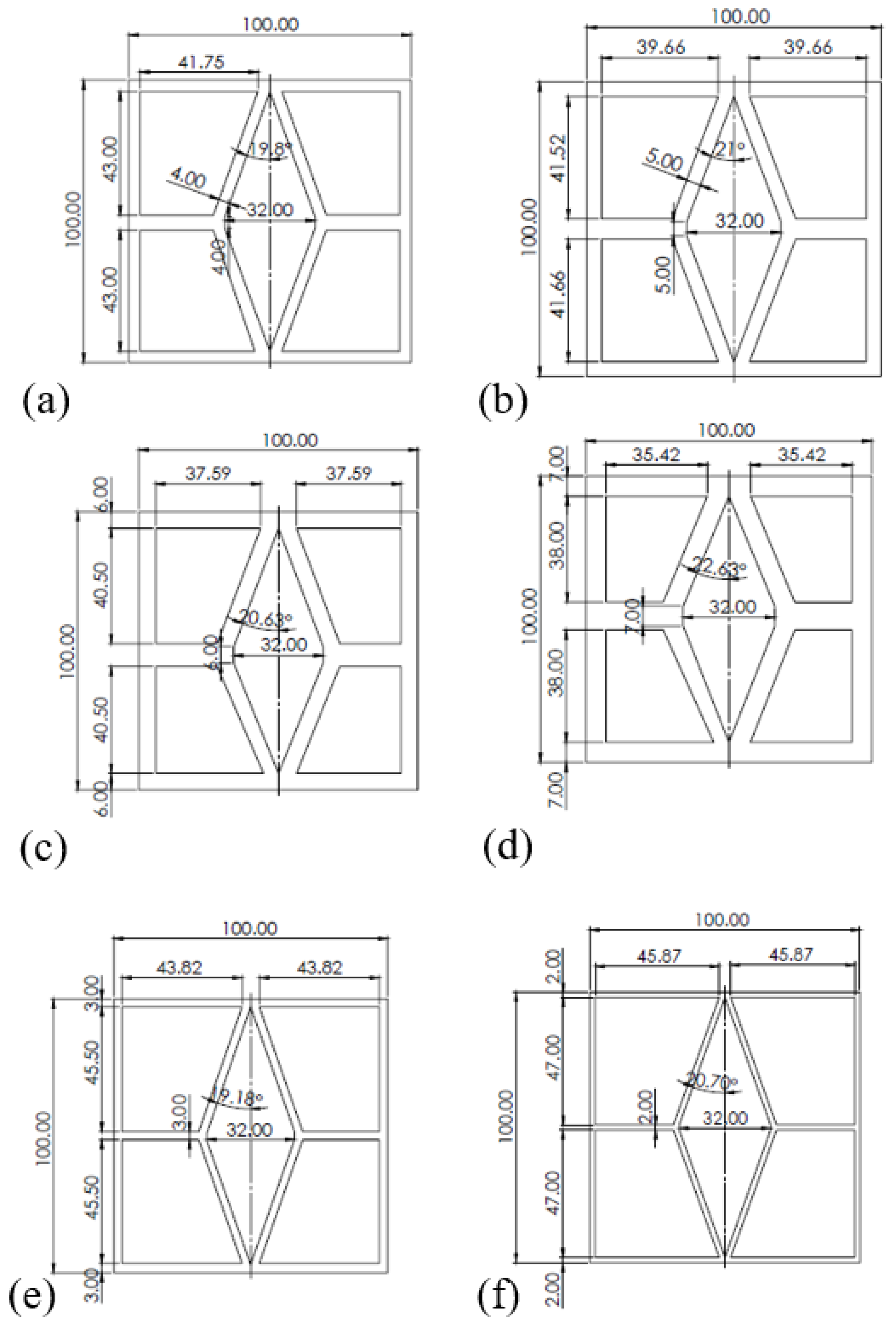
Figure 8.
Roadmap of FEM Studies for a column.
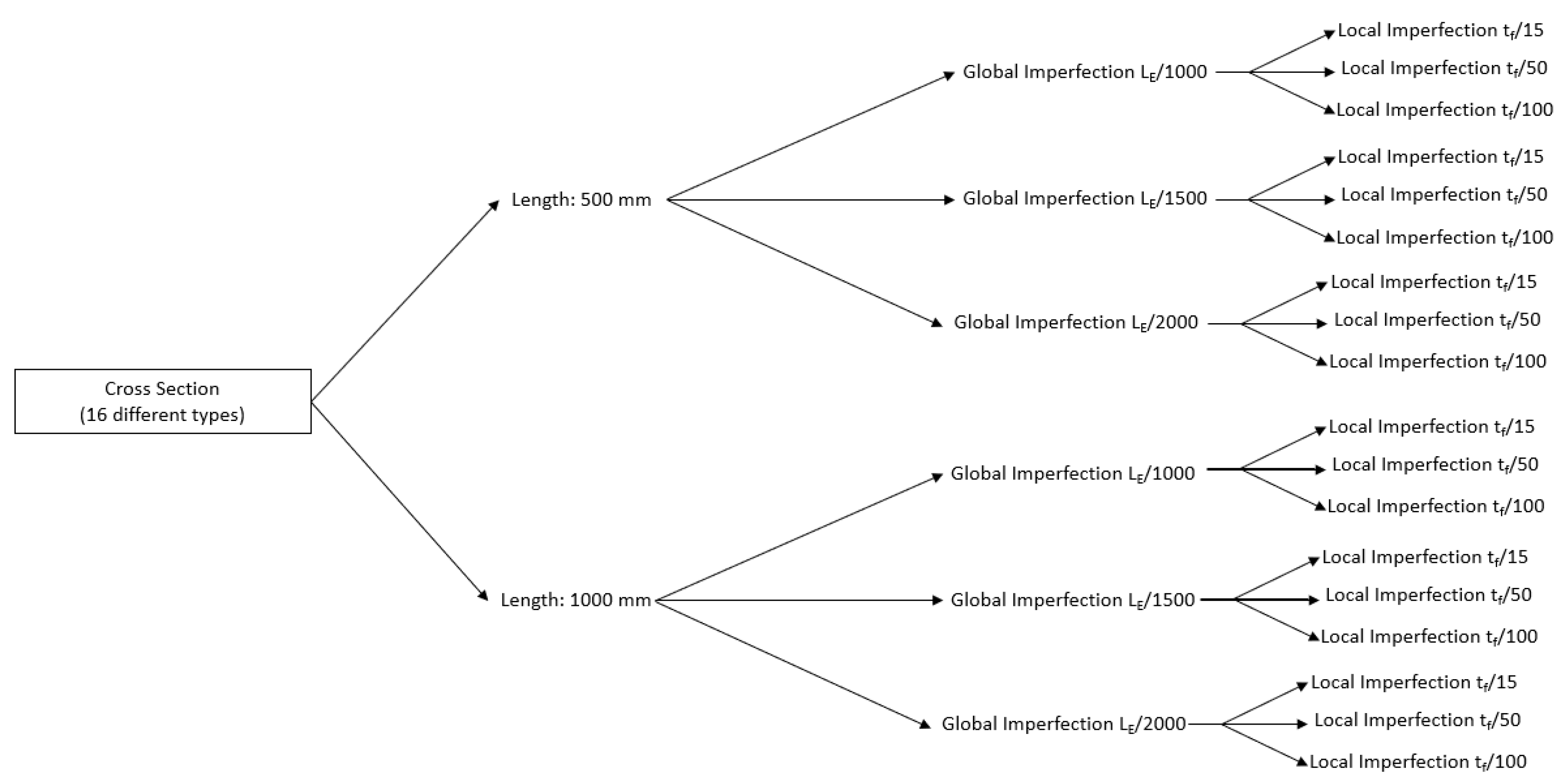
Figure 9.
Some examples of buckling results of various columns with equivalent stress contours (MPa) (a) N2-0.5 m, (b) B1-0.5 m, (c) N4 – 1 m, (d) A4- 1 m.
Figure 9.
Some examples of buckling results of various columns with equivalent stress contours (MPa) (a) N2-0.5 m, (b) B1-0.5 m, (c) N4 – 1 m, (d) A4- 1 m.
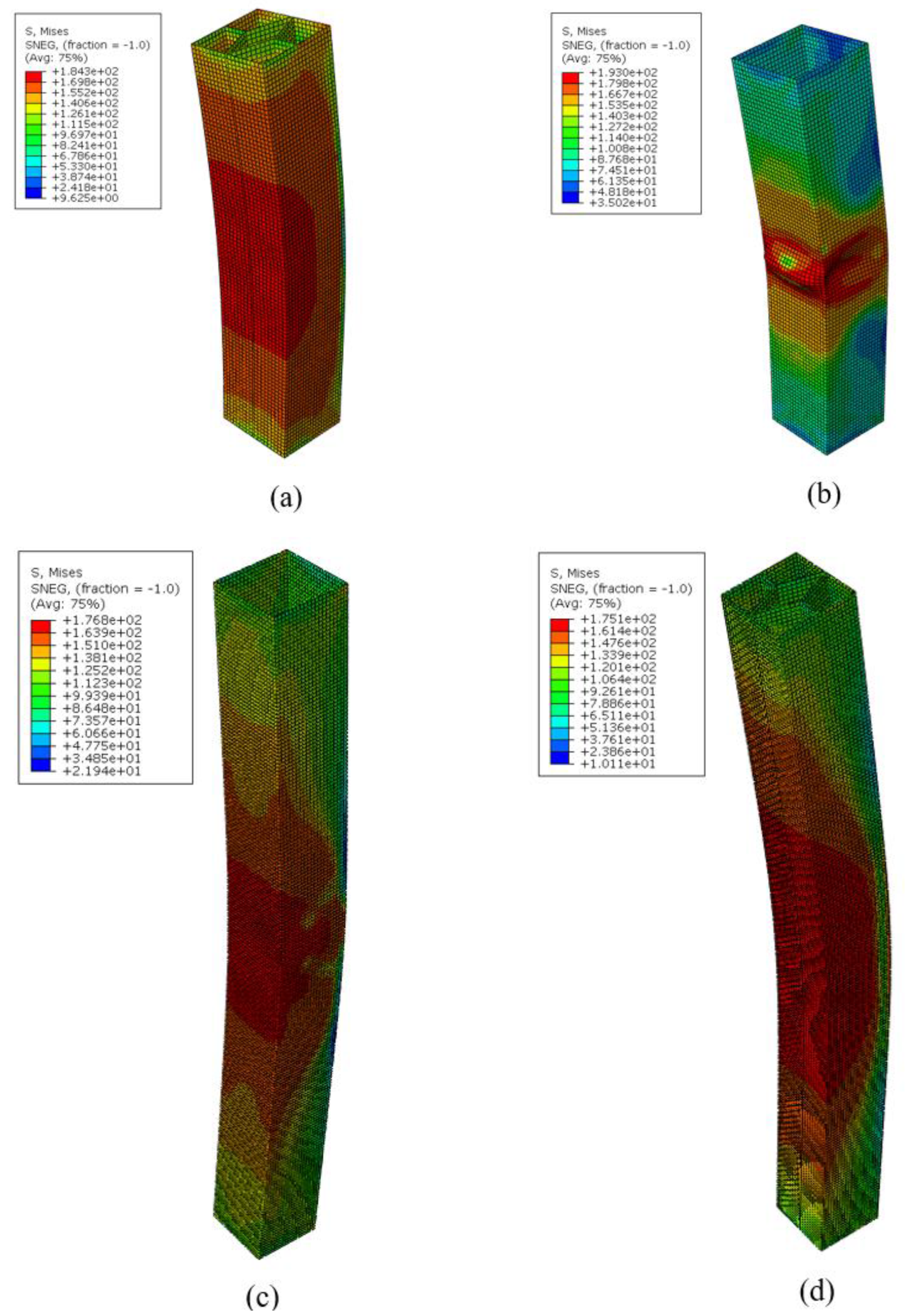
Figure 10.
Methods comparison with respect to FEM results of 0.5 m columns (a): FEM vs. EC-9, (b): FEM vs. DSM, (c): FEM vs. CSM.
Figure 10.
Methods comparison with respect to FEM results of 0.5 m columns (a): FEM vs. EC-9, (b): FEM vs. DSM, (c): FEM vs. CSM.
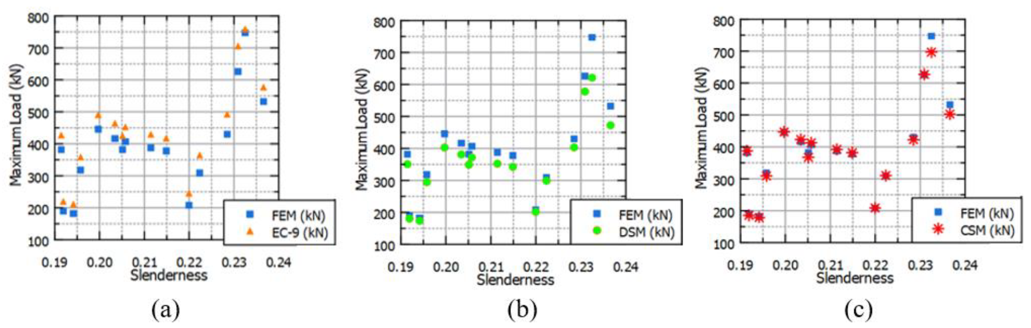
Figure 11.
Methods comparison with respect to FEM results of 1 m columns (a): FEM vs. EC-9, (b): FEM vs. DSM, (c): FEM vs. CSM.
Figure 11.
Methods comparison with respect to FEM results of 1 m columns (a): FEM vs. EC-9, (b): FEM vs. DSM, (c): FEM vs. CSM.
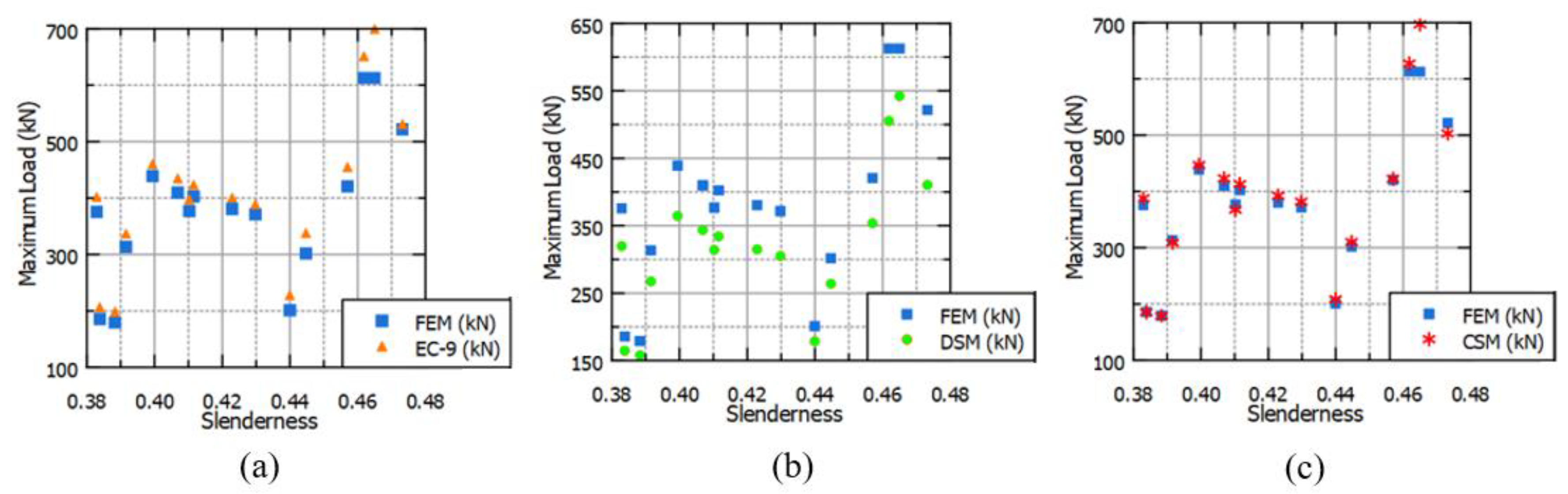
Figure 12.
Change of Load Ratios with Slenderness (a): 0.5 m columns (b): 1 m columns.
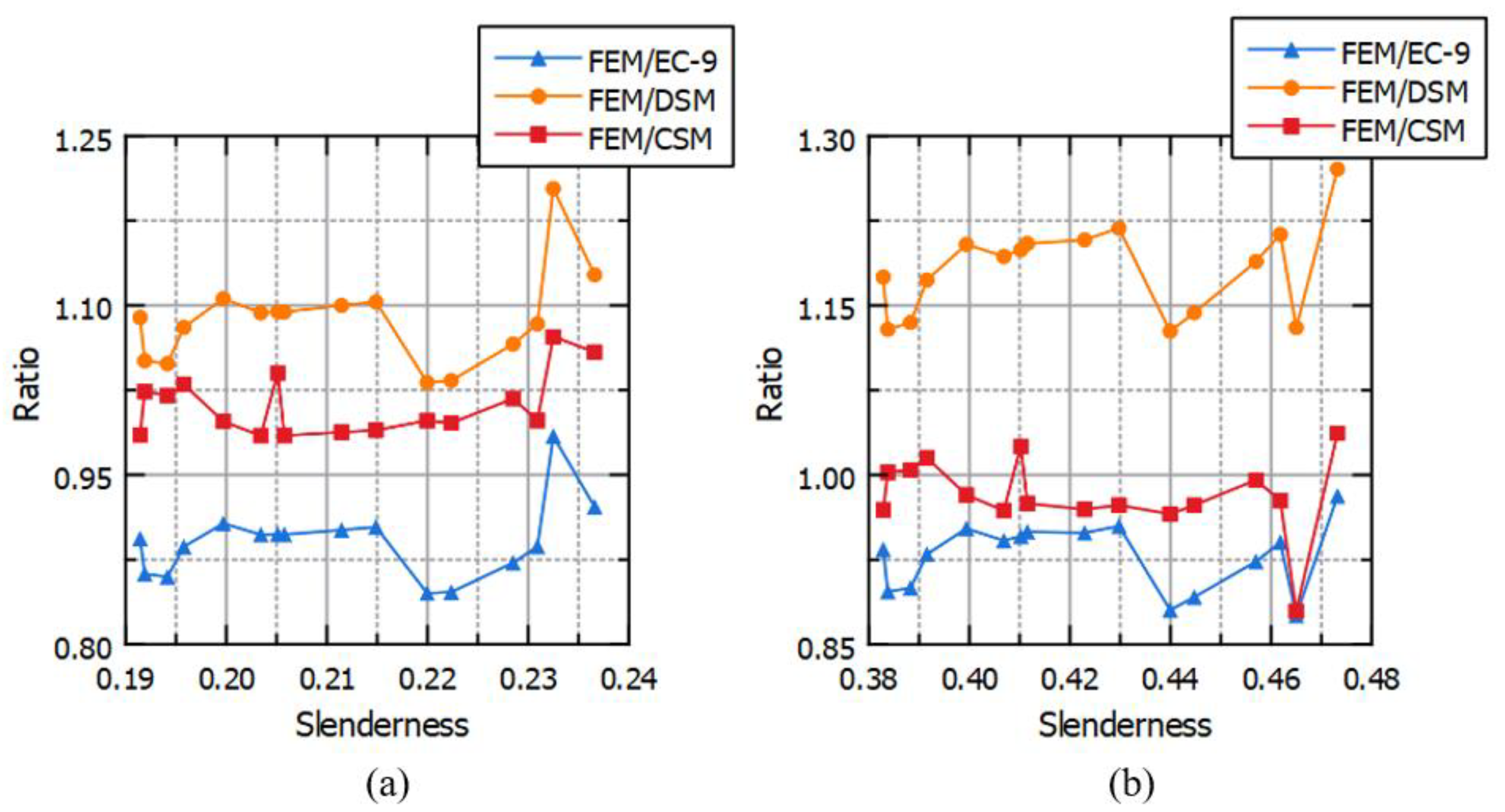

Table 1.
Results of Georgantzia et al. [39] and ABAQUS model.
Table 1.
Results of Georgantzia et al. [39] and ABAQUS model.
| Results | Ultimate Load (kN) | |
|---|---|---|
| Georgantzia et al. | 2023 - test | 225.9 |
| Georgantzia et al. | 2023- FEM | 229.0 |
| FEM - ABAQUS | 231.0 |
Table 2.
Maximum load results comparison between [39] and each calculation method.
Table 2.
Maximum load results comparison between [39] and each calculation method.
| Test | Paper-FEM | FEM | EC9 | DSM | CSM |
|---|---|---|---|---|---|
| 226 kN | 229 kN | 231 kN | 203.5 kN | 212.4 kN | 231 kN |
| Ratio39 | 1.014 | 1.022 | 0.901 | 0.939 | 1.022 |
Table 3.
Cross Section Dimensions.
| Cross Section Codes | B (mm) | H (mm) | t-wall (mm) | t-flange (mm) | inner filet (mm) | outer filet (mm) |
|---|---|---|---|---|---|---|
| A1 | 100 | 100 | 5 | 5 | - | - |
| A2 | 100 | 100 | 7 | 7 | - | - |
| A3 | 100 | 100 | 7 | 5 | - | - |
| A4 | 100 | 100 | 5 | 7 | - | - |
| A5 | 100 | 100 | 3 | 3 | - | - |
| B1 | 100 | 100 | 7 | 7 | 8 | 15 |
| B2 | 100 | 100 | 7 | 7 | 13 | 20 |
| B3 | 100 | 100 | 7 | 7 | 23 | 30 |
| B4 | 100 | 100 | 7 | 7 | 28 | 35 |
| B5 | 100 | 100 | 3 | 3 | 7 | 10 |
| N1 | 100 | 100 | 4 | 4 | - | - |
| N2 | 100 | 100 | 5 | 5 | - | - |
| N3 | 100 | 100 | 6 | 6 | - | - |
| N4 | 100 | 100 | 7 | 7 | - | - |
| N5 | 100 | 100 | 3 | 3 | - | - |
| N6 | 100 | 100 | 2 | 2 | - | - |
Table 4.
Cases of analyses.
| Cross Sections | Column Length 1 (mm) | Column Length 2 (mm) | Global Imperfection - 1 | Global Imperfection - 2 | Global Imperfection - 3 | Local Imperfection - 1 | Local Imperfection - 2 | Local Imperfection - 3 |
|---|---|---|---|---|---|---|---|---|
| A1 | 500 | 1000 | Le/1000 | Le/1500 | Le/2000 | tf/15 | tf/50 | tf/100 |
| A2 | 500 | 1000 | Le/1000 | Le/1500 | Le/2000 | tf/15 | tf/50 | tf/100 |
| A3 | 500 | 1000 | Le/1000 | Le/1500 | Le/2000 | tf/15 | tf/50 | tf/100 |
| A4 | 500 | 1000 | Le/1000 | Le/1500 | Le/2000 | tf/15 | tf/50 | tf/100 |
| A5 | 500 | 1000 | Le/1000 | Le/1500 | Le/2000 | tf/15 | tf/50 | tf/100 |
| B1 | 500 | 1000 | Le/1000 | Le/1500 | Le/2000 | tf/15 | tf/50 | tf/100 |
| B2 | 500 | 1000 | Le/1000 | Le/1500 | Le/2000 | tf/15 | tf/50 | tf/100 |
| B3 | 500 | 1000 | Le/1000 | Le/1500 | Le/2000 | tf/15 | tf/50 | tf/100 |
| B4 | 500 | 1000 | Le/1000 | Le/1500 | Le/2000 | tf/15 | tf/50 | tf/100 |
| B5 | 500 | 1000 | Le/1000 | Le/1500 | Le/2000 | tf/15 | tf/50 | tf/100 |
| N1 | 500 | 1000 | Le/1000 | Le/1500 | Le/2000 | tf/15 | tf/50 | tf/100 |
| N2 | 500 | 1000 | Le/1000 | Le/1500 | Le/2000 | tf/15 | tf/50 | tf/100 |
| N3 | 500 | 1000 | Le/1000 | Le/1500 | Le/2000 | tf/15 | tf/50 | tf/100 |
| N4 | 500 | 1000 | Le/1000 | Le/1500 | Le/2000 | tf/15 | tf/50 | tf/100 |
| N5 | 500 | 1000 | Le/1000 | Le/1500 | Le/2000 | tf/15 | tf/50 | tf/100 |
| N6 | 500 | 1000 | Le/1000 | Le/1500 | Le/2000 | tf/15 | tf/50 | tf/100 |
Table 5.
FEM results and EC-9 results.
| Cross Section Code | Length (m) | FEM - Average (kN) | EC-9 (kN) | FEM/EC9 |
|---|---|---|---|---|
| A1 | 0.5 | 318.1 | 358.9 | 0.89 |
| A1 | 1 | 313.5 | 337.2 | 0.93 |
| A2 | 0.5 | 445.7 | 491.4 | 0.91 |
| A2 | 1 | 439 | 460.8 | 0.95 |
| A3 | 0.5 | 382.1 | 425.8 | 0.90 |
| A3 | 1 | 376.7 | 398.3 | 0.95 |
| A4 | 0.5 | 382 | 427.5 | 0.89 |
| A4 | 1 | 375.8 | 402.4 | 0.93 |
| A5 | 0.5 | 189.8 | 220.1 | 0.86 |
| A5 | 1 | 185.8 | 207.2 | 0.90 |
| B1 | 0.5 | 416.7 | 464.5 | 0.90 |
| B1 | 1 | 409.9 | 435.2 | 0.94 |
| B2 | 0.5 | 406.6 | 453.2 | 0.90 |
| B2 | 1 | 402.5 | 423.8 | 0.95 |
| B3 | 0.5 | 387.5 | 430 | 0.90 |
| B3 | 1 | 380.4 | 400.9 | 0.95 |
| B4 | 0.5 | 377.8 | 418 | 0.90 |
| B4 | 1 | 371.6 | 389.2 | 0.95 |
| B5 | 0.5 | 182 | 211.7 | 0.86 |
| B5 | 1 | 179.2 | 199.1 | 0.90 |
| N1 | 0.5 | 429.8 | 492.8 | 0.87 |
| N1 | 1 | 420.5 | 455.4 | 0.92 |
| N2 | 0.5 | 532.4 | 577.7 | 0.92 |
| N2 | 1 | 521.5 | 531.4 | 0.98 |
| N3 | 0.5 | 626.1 | 706.2 | 0.89 |
| N3 | 1 | 613 | 651.8 | 0.94 |
| N4 | 0.5 | 747.3 | 759.3 | 0.98 |
| N4 | 1 | 612.9 | 699.9 | 0.88 |
| N5 | 0.5 | 308.9 | 365 | 0.85 |
| N5 | 1 | 301.9 | 338.5 | 0.89 |
| N6 | 0.5 | 208 | 246.1 | 0.85 |
| N6 | 1 | 201.2 | 228.5 | 0.88 |
| Mean | 0.91 | |||
| COV | 0.04 |
Table 6.
FEM results and DSM results.
| Cross Section Code | Length (m) | FEM - Average (kN) | DSM (kN) | FEM/DSM |
|---|---|---|---|---|
| A1 | 0.5 | 318.1 | 294.4 | 1.08 |
| A1 | 1 | 313.5 | 267.4 | 1.17 |
| A2 | 0.5 | 445.7 | 403 | 1.11 |
| A2 | 1 | 439 | 364.6 | 1.2 |
| A3 | 0.5 | 382.1 | 349.1 | 1.09 |
| A3 | 1 | 376.7 | 314.1 | 1.2 |
| A4 | 0.5 | 382 | 350.7 | 1.09 |
| A4 | 1 | 375.8 | 319.8 | 1.18 |
| A5 | 0.5 | 189.8 | 180.6 | 1.05 |
| A5 | 1 | 185.8 | 164.6 | 1.13 |
| B1 | 0.5 | 416.7 | 381.1 | 1.09 |
| B1 | 1 | 409.9 | 343.5 | 1.19 |
| B2 | 0.5 | 406.6 | 371.6 | 1.09 |
| B2 | 1 | 402.5 | 334.1 | 1.2 |
| B3 | 0.5 | 387.5 | 352.3 | 1.1 |
| B3 | 1 | 380.4 | 314.9 | 1.21 |
| B4 | 0.5 | 377.8 | 342.5 | 1.1 |
| B4 | 1 | 371.6 | 305 | 1.22 |
| B5 | 0.5 | 182 | 173.6 | 1.05 |
| B5 | 1 | 179.2 | 157.9 | 1.13 |
| N1 | 0.5 | 429.8 | 403.3 | 1.07 |
| N1 | 1 | 420.5 | 353.7 | 1.19 |
| N2 | 0.5 | 532.4 | 472.4 | 1.13 |
| N2 | 1 | 521.5 | 410.4 | 1.27 |
| N3 | 0.5 | 626.1 | 577.8 | 1.08 |
| N3 | 1 | 613 | 505.4 | 1.21 |
| N4 | 0.5 | 747.3 | 621 | 1.2 |
| N4 | 1 | 612.9 | 542.2 | 1.13 |
| N5 | 0.5 | 308.9 | 298.9 | 1.03 |
| N5 | 1 | 301.9 | 264 | 1.14 |
| N6 | 0.5 | 208 | 201.6 | 1.03 |
| N6 | 1 | 201.2 | 178.5 | 1.13 |
| Mean | 1.13 | |||
| COV | 0.06 |
Table 7.
FEM results and CSM results.
| Cross Section Code | Length (m) | FEM - Average (kN) | CSM (kN) | FEM/CSM |
|---|---|---|---|---|
| A1 | 0.5 | 318.1 | 308.8 | 1.03 |
| A1 | 1 | 313.5 | 308.8 | 1.015 |
| A2 | 0.5 | 445.7 | 446.9 | 0.997 |
| A2 | 1 | 439 | 446.9 | 0.982 |
| A3 | 0.5 | 382.1 | 367.4 | 1.04 |
| A3 | 1 | 376.7 | 367.4 | 1.025 |
| A4 | 0.5 | 382 | 387.8 | 0.985 |
| A4 | 1 | 375.8 | 387.8 | 0.969 |
| A5 | 0.5 | 189.8 | 185.4 | 1.024 |
| A5 | 1 | 185.8 | 185.4 | 1.002 |
| B1 | 0.5 | 416.7 | 423.2 | 0.985 |
| B1 | 1 | 409.9 | 423.2 | 0.969 |
| B2 | 0.5 | 406.6 | 412.9 | 0.985 |
| B2 | 1 | 402.5 | 412.9 | 0.975 |
| B3 | 0.5 | 387.5 | 392.3 | 0.988 |
| B3 | 1 | 380.4 | 392.3 | 0.97 |
| B4 | 0.5 | 377.8 | 381.8 | 0.99 |
| B4 | 1 | 371.6 | 381.8 | 0.973 |
| B5 | 0.5 | 182 | 178.4 | 1.02 |
| B5 | 1 | 179.2 | 178.4 | 1.004 |
| N1 | 0.5 | 429.8 | 422.4 | 1.018 |
| N1 | 1 | 420.5 | 422.4 | 0.996 |
| N2 | 0.5 | 532.4 | 502.9 | 1.059 |
| N2 | 1 | 521.5 | 502.9 | 1.037 |
| N3 | 0.5 | 626.1 | 627.2 | 0.998 |
| N3 | 1 | 613 | 627.2 | 0.977 |
| N4 | 0.5 | 747.3 | 696.9 | 1.072 |
| N4 | 1 | 612.9 | 696.9 | 0.879 |
| N5 | 0.5 | 308.9 | 310.2 | 0.996 |
| N5 | 1 | 301.9 | 310.2 | 0.973 |
| N6 | 0.5 | 208 | 208.4 | 0.998 |
| N6 | 1 | 201.2 | 208.4 | 0.965 |
| Mean | 0.99 | |||
| COV | 0.03 |
Disclaimer/Publisher’s Note: The statements, opinions and data contained in all publications are solely those of the individual author(s) and contributor(s) and not of MDPI and/or the editor(s). MDPI and/or the editor(s) disclaim responsibility for any injury to people or property resulting from any ideas, methods, instructions or products referred to in the content. |
© 2024 by the authors. Licensee MDPI, Basel, Switzerland. This article is an open access article distributed under the terms and conditions of the Creative Commons Attribution (CC BY) license (http://creativecommons.org/licenses/by/4.0/).
Copyright: This open access article is published under a Creative Commons CC BY 4.0 license, which permit the free download, distribution, and reuse, provided that the author and preprint are cited in any reuse.


