
Submitted:
14 September 2024
Posted:
17 September 2024
You are already at the latest version
Abstract
A novel approach to optimizing turbomachinery performance is presented in this chapter, which integrates Computational Fluid Dynamics (CFD) simulations, an artificial neural network (ANN) with a modified Non-dominated Sorting Genetic Algorithm II (NSGA-II). Using this enhanced algorithm, substantial performance improvements can be achieved through geometric optimization. The effectiveness of this method is demonstrated in two case studies: an inducer for a centrifugal pump and a Savonius wind turbine. The inducer is designed to maximize head coefficient, hydraulic efficiency, and net positive suction head by optimizing factors such as inlet and outlet blade angles. The optimization process employs the Group Method of Data Handling (GMDH) for objective function modeling, followed by Pareto front plotting and TOPSIS for identifying trade-off optimal points. Results indicate significant improvements in head coefficient, hydraulic efficiency, and NPSHR by 14.3%, 0.3%, and 30.2%, respectively. Twist angle, aspect ratio, and overlap ratio are also optimized for wind turbine blades. The power coefficient is enhanced by 5.32%, the torque coefficient by 13.74%, and the rotational speed by 0.071% through multi-objective optimization. As a result of this approach, efficiency improves, and valuable insights into the optimal design principles for turbomachinery components are also gained.
Keywords:
Computational Fluid Dynamics
; NSGA-II
; Artificial Neural Network
; Turbomachinery
; Optimization
1. Introduction
Optimizing the efficiency and reliability of turbomachinery such as turbines and compressors is a crucial aspect of aerodynamic design. Balancing complex design constraints with performance requirements is often difficult when using traditional methods. Researchers and engineers have turned to advanced computational techniques that synergistically combine evolutionary algorithms, artificial neural networks, and computational fluid dynamics to overcome these challenges [1,2]. It is explored in this chapter how these methodologies can be integrated to enhance the aerodynamic design process, offering unprecedented capabilities for optimizing turbomachinery geometries.
In the field of multi-objective optimization, NSGA-II is considered to be a cornerstone [3]. Also finding Pareto-optimal solutions implies that no other solution will improve one objective without worsening another- it is also capable of handling multiple conflicting objectives efficiently [4]. Several modifications have been made to NSGA-II to tailor it specifically to the challenges of aerodynamic design, improving its ability to navigate the complex, multidimensional design space inherent in turbomachinery optimization [5,6].
ANNs, inspired by biological neural networks, excel in learning complex patterns and relationships from data. In the context of aerodynamic optimization, ANNs serve as surrogate models or metamodels [7]. They mimic the behavior of CFD simulations, providing rapid predictions of aerodynamic performance metrics across various design configurations. This capability significantly reduces computational expense, enabling iterative refinement of designs without the need for exhaustive CFD evaluations [8].
CFD simulations are indispensable for accurately predicting the flow behavior within turbomachinery components. They provide detailed insights into aerodynamic performance metrics such as pressure distribution, flow separation, and efficiency. However, conducting numerous CFD simulations can be computationally intensive and time-consuming, limiting the feasibility of exhaustive design exploration [9].
The integration of modified NSGA-II, ANN, and CFD forms a powerful symbiotic relationship in aerodynamic design optimization. NSGA-II guides the search for Pareto-optimal solutions, leveraging ANN as a surrogate model to rapidly evaluate designs across multiple objectives derived from CFD simulations. This framework allows engineers to efficiently explore the design space, identifying optimal configurations that balance conflicting objectives like pressure distribution, efficiency, and stability.
By combining these methodologies, engineers can achieve several benefits:
- Efficiency: Reduced computational costs through ANN-based surrogate models accelerate the design iteration process.
- Precision: Enhanced accuracy in predicting aerodynamic performance metrics ensures designs meet stringent performance requirements.
- Innovation: Facilitated exploration of novel design configurations that may not be apparent through traditional methods.
This chapter delves into the integration of modified NSGA-II algorithm, ANN, and CFD for optimizing aerodynamic geometries of turbomachinery. Through a synergistic approach, these methodologies empower engineers to tackle complex design challenges, ultimately advancing the frontier of aerodynamic efficiency and performance optimization in turbomachinery.
1.2. Literature Review
Significant research has focused on using evolutionary methods for system identification [10]. The GMDH algorithm, introduced by Ivakhnenko [11], is a self-organizing method that can create complex models by evaluating their performance on a set of multi-input, single-output data pairs. Using the GMDH algorithm, an analytical function can be built in a feed-forward network based on a quadratic node transfer function, with coefficients determined through regression techniques.
To find the optimal values, the first step is to establish the explicit mathematical input-output relation [12]. This relationship can be determined through system identification methods, including fuzzy logic, neural networks, and evolutionary algorithms [13].
Once the mathematical input-output relationships are established, a multi-objective optimization method should be applied to enhance inducer performance. In multi-objective optimization problems, a set of optimal solutions, known as the Pareto front, is identified [14]. Genetic algorithms, which are evolutionary algorithms, are particularly effective for solving both single-objective and multi-objective optimization problems due to their inherent capabilities [15].
Recent studies focusing on turbomachinery have explored various approaches: Deb et al. [16] recommended using the NSGA-II multi-objective optimization algorithm, derived from genetic algorithms. This algorithm faced challenges in handling problems with more than two objective functions due to limitations in its diversity subprogram [17]. To address these issues and improve the NSGA-II algorithm, the ε-elimination subprogram was incorporated, enhancing the genetic algorithm. This modified approach has been successfully applied to several multi-objective optimization problems [18,19].
Hadi Al-Gburi et al. [20] introduced an innovative method for optimizing the blade geometry and guide gap flow of Savonius wind turbines. They found that increasing overlap distances led to reduced efficiency, as the returning flow became turbulent and interfered with the forward blade's directed flow. Chan et al. [21] focused on improving the pressure coefficient of Savonius turbines by optimizing the blade shape. They proposed a new blade geometry and analyzed it using genetic algorithms (GA) and CFD. The results showed that the optimized blade performed better than previous models.
Marinić-Kragić et al. [22] concentrated on optimizing Savonius wind turbine deflector blades, achieving significant gains in power coefficient, particularly with Scooplet-based designs. In another study, they [23] integrated a genetic algorithm with CFD modeling to further improve the power coefficient of the Savonius wind turbine. They introduced a new two-blade design that enhanced power efficiency by 12% and made improvements to Scooplet-based designs for four- and six-blade configurations, which achieved power efficiency coefficients of 0.32 and 0.34, respectively. Bedon et al. [24] developed a database generation technique validated for symmetric profiles, which led to better wind turbine performance. Jafaryar et al. [25] conducted a numerical study using central composite design to find an optimal design for VAWT blades with asymmetric geometry. Mohamad et al. [26] suggested using symmetric airfoil blades with coupled optimization and CFD algorithms to increase the tangential force of the Wells monoplane turbine, resulting in improved output power and efficiency.
1.3. Aims
This chapter aims to investigate a combined methodology involving algorithms like modified NSGA-II, GMDH, and CFD to optimize turbomachinery geometry. The CFD technique is proposed for predicting the performance of turbomachinery, with objective functions defined as cost functions. The GMDH method is used to create polynomial models of these objective functions, based on important geometric parameters as design variables. These models are then applied within a multi-objective optimization framework using a modified NSGA-II algorithm to find optimal solutions along the Pareto front. TOPSIS is used to identify trade-off optimal points. By integrating these methods, the chapter seeks to significantly improve the performance and efficiency of turbomachinery designs. The effectiveness of these methodologies is illustrated through detailed case studies on the Savonius wind turbine and a centrifugal pump inducer.
2. Modelling using GMDH
Ivakhnenko [11] first introduced GMDH algorithm, which is designed to model complex systems based on data with several inputs and a single output. The GMDH network creates a function within a feed-forward network using a second-degree transfer function, with coefficients derived through regression methods. The relationship between inputs and outputs is described by a Volterra series (Equation (1)) and can be formulated as a system of two-variable second-degree polynomials (Equation (2)).
The unknown coefficients (ai) are calculated with regression methods for each pair of xi and xj input variables. These coefficients should be obtained such that the least squares error between each quadratic function (Gi) and the actual output (yi) is minimized (Equations (3) and (4)).
The complete mathematical representation of the GMDH algorithm can be found in [11].
The GMDH algorithm is employed to find the polynomial representation of the output parameters in the present work.
The performance of the artificial neural network is evaluated according to root-mean-square error (RMSE), absolute fraction of variance (R2) and mean relative error (MRE) which are defined as follows:
where t represents the target value, o denotes the output value, and P stands for the pattern number.
3. Multi-Objective Optimization
A multi-objective optimization problem can be defined mathematically as searching for a vector of design variables (,) which satisfies m inequality constraints and p equality constraints:
to optimize the vector of objective functions:
In essence, all objective functions in a problem need to be optimized at the same time. Because these objectives often conflict, improving one will generally worsen another. As a result, rather than finding a single best solution for all objectives, a set of optimal solutions, referred to as the Pareto front, is identified [14].
These optimal solutions are non-dominated with respect to each other but surpass other solutions within the objective function space. This implies that enhancing one objective function on the Pareto front will inevitably result in the decline of another. Consequently, adjusting the design variables tied to these objective functions cannot improve all objectives at the same time. Therefore, it can be concluded that each solution on the Pareto front represents a trade-off, where one objective is sacrificed in favor of another.
To explain mathematically, if we assume that all objectives should be minimized (without loss of generality) a vector is dominant to vector (denoted by ) if and only if . In other words, there is at least one uj which is smaller than vj whilst the remaining u’s are either smaller or equal to corresponding v’s.
A point (Ω is a feasible region in ) is said to be Pareto optimal (minimal) with respect to all X∈Ω if and only if . Alternatively, it can be readily restated as . In other words, the solution X* is said to be Pareto optimal (minimal) if no other solution can be found to dominate X* using the definition of Pareto dominance. For a given multi-objective optimization problem, a Pareto set is a set in the decision variable space consisting of all the Pareto optimal vectors . In other words, there is no other as a vector of decision variable in Ω that dominates any .
A Pareto front is a set of vector of objective functions which are obtained using the vectors of decision variables in the Pareto set, that is. In other words, the Pareto front is a set of the vectors of the objective functions mapped from .
Due to their population-based search approach, evolutionary algorithms are highly effective for multi-objective optimization problems. These algorithms address the limitations of classical methods, such as the need for numerous runs to discover the Pareto front or the use of numerical weights to quantify the importance of each objective. Maintaining adequate genetic diversity in the population is crucial in these approaches to avoid premature convergence and to ensure the solutions are well-distributed along the true Pareto front.
As an evolutionary algorithm, NSGA-II uses a crowding approach, which is not very effective as a diversity-preserving operator, particularly in problems involving more than two objective functions. In these situations, the crowding distance calculated by the NSGA-II routine can produce unclear or ambiguous values.
The key difference between the modified NSGA-II and the original NSGA-II is the replacement of the crowding distance assignment method with the ε-elimination diversity approach. This method removes clones and/or ε-similar individuals from the current population by calculating the Euclidean norm between two vectors. By defining ε as the elimination threshold (0.001 in this study), all individuals within this range of a specific individual on a front are eliminated. To ensure that distinct individuals in the design variable space with ε-similarity in the objective function space are not eliminated, ε-similarity is applied in both the objective and design variable spaces. The eliminated individuals are then substituted with randomly generated ones from the population. This method also improves the efficiency of exploring the search space [18,19,27].
4. TOPSIS
TOPSIS is a method for multi-criteria decision analysis, utilized to rank the alternatives within the obtained Pareto solutions. The method aims to find the optimal compromise solution according to the designer’s assigned objective weights.
The chosen non-dominated solution (Alternative) should have the shortest distance from the determined positive ideal solution (A+) and farthest distance from the determined negative ideal solution (A-). In order to choose the best compromise solution, an evaluation matrix (xij)m×n should be created (m alternatives and n criteria). xij is also, the jth objective value of the ith alternative. The created matrix should then be normalized to form the matrix R using Equation (9):
The weighted normalized decision matrix is calculated as follows:
where wj is the weight given by the designer, so that .
The best and the worst alternatives (A+ and A-) should be determined at the next step:
where j associated with the criteria having a positive impact and j associated with the criteria having a negative impact.
Then, the distances from the target alternative i to the best (dib) and worst (diw) conditions should be calculated.
Finally, the relative closeness to the ideal solution () is calculated and the best compromise solution whose relative closeness is the closest to 1 is chosen.
5. Results
Based on the proposed method, we investigated the combination of the modified NSGA-II algorithm, CFD, and ANN. Two different turbomachines will be examined, namely a Savonius wind turbine and a centrifugal pump inducer. To investigate the optimum performance of the turbomachinery, the obtained polynomial neural network models are now incorporated into a multi-objective optimization procedure. A modified NSGA-II approach is used to implement the evolutionary process of Pareto multi-objective optimization.
5.1. Savonius Wind Turbine
Two twisted blades are attached to the central shaft to transmit torque. A three-dimensional wind turbine model developed by Hosseini et al. [28] is used in the simulations presented in Table 1 and Figure 1.
based on the available data in the literature [29,30,31,32], the shear stress transport (SST) model was selected as the most appropriate model , with further details on the solver and governing equations provided by Hosseini et al [28].
Artificial neural networks are designed based on the parameters listed in Table 2. The turbine construction takes into account all operating conditions at the design points. Based on the specifications reported in Table 3, 60 different geometries were generated. Based on our CFD analysis, we have determined these different geometries separately. Three key design parameters that greatly impact turbine performance are the blade twist angle, aspect ratio, and overlap ratio. To optimize the turbine through Pareto-based multi-objective analysis, a modified NSGA-II algorithm will be utilized.
Figure 2 shows the ANN structure for the objective functions, including the power and torque coefficients as well as the rotational speed. The same structure is applied in all three scenarios.
Equations (13)–(15) present the ANN polynomials for the turbine's power coefficient, torque coefficient, and rotational speed.
In this scenario, the GA operators are reapplied to generate the next generation, with the goal of achieving the Pareto optimal solution. A modified NSGA-II, utilizing non-dominated sorting, was employed for the multi-objective optimization of turbine performance, taking into account the previously mentioned geometric and evaluation parameters. Polynomial ANNs were utilized to optimize performance. The three objective functions—torque coefficient, rotational speed, and power coefficient—were optimized based on design variables. The NSGA-II algorithm was modified to facilitate Pareto evolutionary optimization with multiple objectives. The problem is assessed using the following formulation:
Note that instead of maximizing the torque coefficient, rotational speed, and power coefficient, the inverse functions, namely 1/CT, 1/ω, and 1/Cp, are minimized.
For the three-objective optimization problem in 1000 generations, a population size of 200 is assumed with cross-over and mutation probabilities of 0.75 and 0.075, respectively. It is possible to plot individuals in different objective function planes as a result of solving this three-objective optimization problem. Using the same design variables, two-objective and multi-objective optimization problems are compared.
The optimal design points from the three-objective and two-objective optimizations overlap, as shown in Figure 3(a). Additional design points on other planes are illustrated in Figures 3(b) and (c). The front points in Pareto solutions are considered the best, making their corresponding design variables the most desirable. If different design variables were selected, the resulting two-objective values would rank lower than those on the Pareto front. Selecting design variables according to the Pareto set provides the best combination of all three objectives. On each plane, while the Pareto front points dominate each other, they are still superior to other points.
As shown in Figure 3, the results of three-objective optimization in each plane include the results obtained from a two-objective problem, providing designers with more choices. Furthermore, the results of the two-objective optimization are located at the boundary of the three-objective problem, indicating the validity of the results.
According to Figure 3, the values of 1/CT obtained using the two-objective problem are the same as those obtained using the modified NSGA-II. As a result, it is evident that selecting 1/Cp as an objective function gives the same results as choosing 1/CT; therefore, they can be used interchangeably. 1/rotational speed is the result of 1/Cp and 1/CT drops. As 1/Cp increases, the 1/CT increases, but pressure has a much lower contribution to rotational speed than torque. Therefore, in the wind turbine under consideration, torque dominates rotational speed.
Figure 4 compares the pressure and fluid velocity of the original and optimized turbines. In Figure 4(a), the original turbine exhibits a larger high-pressure area compared to the optimized turbine. However, the modified turbine demonstrates a higher pressure gradient across the driving blade, which results in increased torque. Figure 4(b) shows that both turbines experience backward flow towards the retreating blades, but this backflow is more pronounced in the optimized turbine, contributing to improved torque. Additionally, the overlap ratio enhances the fluid's ability to enter and exit the turbine more smoothly, particularly in the optimized turbine. Consequently, the optimized turbine experiences fewer losses and blockages, leading to overall improved performance.
The flow of air from the advancing blade to the retreating blade increases pressure on the suction side of the opposite blade, which in turn affects the rotor's performance. The presence of low-pressure regions on the ascending blades suggests that rotor rotation and power output can be positively influenced by a new rotor design. Based on the results, it can be concluded that the optimized blade design could be utilized to enhance the performance of large-scale wind rotors. Additionally, the findings for the two-bladed wind turbines indicate that the new turbine design significantly impacts the discharge flow rate, while causing only negligible reductions in the turbine's power coefficient.
5.2. Centrifugal Pump Inducer
The schematic of the inducer used in the simulation is shown in Figure 5. This inducer is a three-bladed, tapered-hub, variable-pitch design, with its main geometrical and operational parameters detailed in Table 4 [33]. The inducer is simulated using CFD software. To simulate the flow characteristics, the conservation equations for mass and momentum must be solved. Additionally, since the flow is three-dimensional and turbulent, transport equations for the turbulence model are also solved. The governing equations for the numerical simulation are based on the assumptions of steady-state conditions and an incompressible fluid [33]. Based on the comparison results, the complex flow behavior, and the available data in the literature [34,35,36,37], the renormalization group (RNG) k-ε model was selected as the most appropriate model.
The design variables, along with their ranges of variation, are detailed in Table 5. A sample of the numerical simulation results used for training and testing the artificial neural network is provided in Table 6.
The structure of the GMDH neural network for various output parameters is shown in Figure 6. The corresponding polynomials for 1/hydraulic efficiency, 1/head coefficient, and NPSHR are provided in Equations (17), (18) and (19), respectively.
In total, 62.5% of the database is used for training, while the remaining 37.5% is reserved for testing. The division between the training and testing datasets is done randomly.
The three objective functions—head coefficient, hydraulic efficiency, and NPSHR—are optimized with respect to the design variables: inlet tip blade angle, outlet tip blade angle, and the ratio of the outlet hub radius to the inlet hub radius. The evolutionary process for this multi-objective optimization is carried out using a modified NSGA-II approach. The problem is formulated as follows:
It should also be noted that, instead of maximizing the head coefficient and hydraulic efficiency directly, the optimization process minimized the parameters 1/head coefficient and 1/hydraulic efficiency.
A population of 100 individuals was evaluated over 1,000 generations for a four-objective optimization problem, with a crossover probability of 0.7 and a mutation probability of 0.07. The result of the three-objective optimization yields a set of individuals that can be visualized in various objective function planes. Additionally, a two-objective optimization was performed using the same design variables and compared with the outcomes of the three-objective optimization
The non-dominated optimal design points from the three-objective optimization, plotted in the plane of NPSHR and 1/η, are overlaid with the results from the two-objective optimization in Figure 7(a). These non-dominated design points are also depicted in other planes, as shown in Figures 7(b) and 7(c).
All Pareto front points in each plane are non-dominated relative to one another but are superior to all other points. Since these Pareto front points represent the best solutions, the corresponding design variables are also the optimal choices. If any other set of design variables is selected, the resulting values for the objectives would be inferior, falling outside the Pareto front. Thus, it can be concluded that basing the selection of design variables on the Pareto sets leads to the best possible combination of the three objectives.
As illustrated in Figure 7, the results from the three-objective optimization encompass those of the two-objective problem in each plane, providing designers with more options. Moreover, the results of the two-objective optimization lie on the boundary of the three-objective problem, confirming the validity of the obtained data.
A comparison between the original and three-objective optimized inducers is presented in Figure 8. The static pressure distributions on the pressure side of the blades (Figure 8(a)) clearly show that the optimized ratio of the outlet hub radius to the inlet hub radius reduces the space between the hub and casing, consequently increasing the pressure difference. Additionally, the fluid velocity vectors (Figure 8(b)) demonstrate that reducing the inlet and outlet tip blade angles allows the fluid to enter and exit the blades more smoothly along their surfaces. This results in a reduction of incidence losses at the blade entrance and mitigates blockage effects at the blade exit. Although more backflows are observed at the blade tips due to the increased pressure difference between the suction and pressure surfaces, these losses constitute a small fraction of the total loss. Overall, the inducer's performance is improved, as evidenced by the optimized head coefficient, hydraulic efficiency, and NPSHR.
Conclusion
A multi-objective optimization technique was implemented in the current study to enhance the efficacy of turbomachinery. A 3-D CFD approach was employed to model turbomachinery. The objective functions were modeled using a GMDH neural network, which was informed by numerical input-output data. Pareto fronts were depicted using polynomial models acquired in an evolutionary multi-objective Pareto-based optimization approach (the modified NSGA-II), and trade-off optimum points were derived using TOPSIS. The results of the overlay of two and three-objective optimization data indicated that the two-objective optimization data were situated within the boundary of the three-objective problem. Some significant trade-offs among objective functions were identified as a result of multi-objective optimization. The combined implementation of NSGA-II and TOPSIS is highly beneficial in the design of turbomachines. The application of single objective optimization resulted in a 55.26% decrease in NPSHR, a 25.37% increase in head coefficient, and a 5.56% increase in hydraulic efficiency for the centrifugal pump inducer. For the Savonius wind turbine, the suggested method improved the torque coefficient, rotational speed, and power coefficient by 13.74%, 0.071%, and 5.32%, respectively.
Conflicts of Interest
The authors declare no conflict of interest.
Nomenclature
| Cµ | constant | ε | rate of dissipation of turbulent kinetic energy (m2/s3) |
| Cɛ1 | constant | η | hydraulic efficiency |
| Cɛ2 | constant | ηo | constant |
| dh | inducer hub diameter (m) | µ | dynamic viscosity (Pa s) |
| Gk | turbulent kinetic energy generation (kg/m s3) | ρ | density (kg/m3) |
| k | turbulent kinetic energy (m2/s2) | σk | effective Prandtl number for k |
| NPSHR | required net positive suction head (m) | σε | effective Prandtl number for ε |
| P | pressure (Pa) | φ | flow coefficient |
| ΔP | pressure drop (Pa) | ψ | head coefficient |
| Q | volumetric flow rate (m3/s) | Ω | inducer rotational speed (rpm) |
| rh | inducer hub radius (m) | subscripts | |
| rT | inducer blade tip radius (m) | eff | effective |
| fluctuating velocity (m/s) | in | inlet | |
| Uj | mean velocity (m/s) | min | minimum |
| Vin | inlet velocity to the inducer (m/s) | out | outlet |
| xj | coordinate (m) | t | total |
| y | output value | ||
| Greek symbols | |||
| β | constant | ||
| βin | inlet tip blade angle (deg) | ||
| βout | outlet tip blade angle (deg) | ||
| δ | Kronecker delta | ||
References
- Safikhani H, Abbassi A, Khalkhali A, Kalteh M. Multi-objective optimization of nanofluid flow in flat tubes using CFD, Artificial Neural Networks and genetic algorithms. Adv Powder Technol. 2014 Sep 1;25(5):1608–17. [CrossRef]
- Lira JOB, Riella HG, Padoin N, Soares C. Computational fluid dynamics (CFD), artificial neural network (ANN) and genetic algorithm (GA) as a hybrid method for the analysis and optimization of micro-photocatalytic reactors: NOx abatement as a case study. Chem Eng J. 2022 Mar 1;431:133771. [CrossRef]
- Verma S, Pant M, Snasel V. A Comprehensive Review on NSGA-II for Multi-Objective Combinatorial Optimization Problems. IEEE Access. 2021;9:57757–91. [CrossRef]
- Ma H, Zhang Y, Sun S, Liu T, Shan Y. A comprehensive survey on NSGA-II for multi-objective optimization and applications. Artif Intell Rev [Internet]. 2023 Dec 1 [cited 2024 Aug 11];56(12):15217–70. Available from: https://link.springer.com/article/10.1007/s10462-023-10526-z. [CrossRef]
- Li Z, Zheng X. Review of design optimization methods for turbomachinery aerodynamics. Prog Aerosp Sci. 2017 Aug 1;93:1–23. [CrossRef]
- Hosseini SE, Jafaripanah S, Saboohi Z. Numerical Simulation and Aerodynamic Optimization of Two-Stage Axial High-Pressure Turbine Blades. 2024 Jan 4 [cited 2024 Jun 8]; Available from: https://arxiv.org/abs/2401.02102v1. [CrossRef]
- Sun G, Wang S. A review of the artificial neural network surrogate modeling in aerodynamic design. 2019 Jul 26 [cited 2024 Aug 11];233(16):5863–72. Available from: https://journals.sagepub.com/doi/abs/10.1177/0954410019864485. [CrossRef]
- Mengistu T, Ghaly W. Aerodynamic optimization of turbomachinery blades using evolutionary methods and ANN-based surrogate models. Optim Eng [Internet]. 2008 Sep 1 [cited 2024 Aug 11];9(3):239–55. Available from: https://link.springer.com/article/10.1007/s11081-007-9031-1. [CrossRef]
- Martins JRRA. Aerodynamic design optimization: Challenges and perspectives. Comput Fluids. 2022 May 15;239:105391. [CrossRef]
- Farlow SJ. Self-organizing methods in modeling: GMDH type algorithms. CRC Press; 1984.
- Ivakhnenko A. Polynomial theory of complex systems. IEEE Trans Syst Man Cybern. 1971;364–78. [CrossRef]
- Åström KJ, Eykhoff P. System identification—A survey. Automatica. 1971 Mar 1;7(2):123–62. [CrossRef]
- Sanchez E, Shibata T, Zadeh L. Genetic algorithms and fuzzy logic systems: Soft computing perspectives. World Sci. 1997;7.
- Coello C. A comprehensive survey of evolutionary-based multiobjective optimization techniques. Knowl Inf Syst. 1999; [CrossRef]
- G Z. Genetic algorithms in search, optimization and machine learning. Inf Tech J. 1981;3(1).
- Deb K, Pratap A, Agarwal S, Meyarivan T. A fast and elitist multiobjective genetic algorithm: NSGA-II. IEEE Trans Evol Comput. 2002;6(2):182–97. [CrossRef]
- Atashkari K, Nariman-Zadeh N, Pilechi A, Jamali A, Yao X. Thermodynamic Pareto optimization of turbojet engines using multi-objective genetic algorithms. Int J Therm Sci. 2005 Nov 1;44(11):1061–71. [CrossRef]
- Shojaeefard MH, Zare J. Modeling and combined application of the modified NSGA-II and TOPSIS to optimize a refrigerant-to-air multi-pass louvered fin-and-flat tube condenser. Appl Therm Eng. 2016 Jun;103:212–25. [CrossRef]
- Shojaeefard MH, Zare J. An Investigation of the Potential of Improving an R1234yf Parallel Flow Condenser Performance Using Modeling and Hybrid Procedure of the Modified NSGA-II and TOPSIS. Heat Transf Eng [Internet]. 2018 Sep 14 [cited 2024 Aug 11];39(15):1405–22. Available from: https://www.tandfonline.com/doi/abs/10.1080/01457632.2017.1366239. [CrossRef]
- Al-Gburi KAH, Alnaimi FBI, Al-quraishi BAJ, Tan ES, Kareem AK. Enhancing Savonius Vertical Axis Wind Turbine Performance: A Comprehensive Approach with Numerical Analysis and Experimental Investigations. Energies 2023, Vol 16, Page 4204 [Internet]. 2023 May 19 [cited 2023 Oct 1];16(10):4204. Available from: https://www.mdpi.com/1996-1073/16/10/4204/htm. [CrossRef]
- Chan CM, Bai HL, He DQ. Blade shape optimization of the Savonius wind turbine using a genetic algorithm. Appl Energy. 2018;213:148–57. [CrossRef]
- Marinić-Kragić I, Vučina D, Milas Z. Robust optimization of Savonius-type wind turbine deflector blades considering wind direction sensitivity and production material decrease. Renew Energy. 2022;192:150–63. [CrossRef]
- Marinić-Kragić I, Vučina D, Milas Z. Global optimization of Savonius-type vertical axis wind turbine with multiple circular-arc blades using validated 3D CFD model. Energy. 2022;241:122841. [CrossRef]
- Bedon G, Castelli MR, Benini E. Optimization of a Darrieus vertical-axis wind turbine using blade element–momentum theory and evolutionary algorithm. Renew Energy. 2013;59:184–92. [CrossRef]
- Jafaryar M, Kamrani R, Gorji-Bandpy M, Hatami M, Ganji DD. Numerical optimization of the asymmetric blades mounted on a vertical axis cross-flow wind turbine. Int Commun Heat Mass Transf. 2016;70:93–104. [CrossRef]
- Mohamed MH, Janiga G, Pap E, Thévenin D. Multi-objective optimization of the airfoil shape of Wells turbine used for wave energy conversion. Energy. 2011;36(1):438–46. [CrossRef]
- Jamali A, Nariman-Zadeh N, Darvizeh A, Masoumi A, Hamrang S. Multi-objective evolutionary optimization of polynomial neural networks for modelling and prediction of explosive cutting process. Eng Appl Artif Intell. 2009;22(4–5):676–87. [CrossRef]
- Hosseini SE, Karimi O, AsemanBakhsh MA. Experimental investigation and multi-objective optimization of savonius wind turbine based on modified non-dominated sorting genetic algorithm-II. Wind Eng [Internet]. 2024 Aug 29 [cited 2023 Aug 29];48(3):446–67. Available from: https://www.preprints.org/manuscript/202308.1937/v1. [CrossRef]
- Almohammadi KM, Ingham DB, Ma L, Pourkashan M. Computational fluid dynamics (CFD) mesh independency techniques for a straight blade vertical axis wind turbine. Energy. 2013 Sep;58:483–93. [CrossRef]
- Shaheen M, El-Sayed M, Abdallah S. Numerical study of two-bucket Savonius wind turbine cluster. J Wind Eng Ind Aerodyn. 2015 Feb;137:78–89. [CrossRef]
- Zare J, Hosseini SE, Rastan MR. Airborne dust-induced performance degradation in NREL phase VI wind turbine: a numerical study. Int J Green Energy [Internet]. 2024 Aug 20 [cited 2023 Aug 25];21(6):1295–314. Available from: https://www.tandfonline.com/doi/abs/10.1080/15435075.2023.2246544. [CrossRef]
- Hosseini SE, Salehi F. Analyzing overlap ratio effect on performance of a modified Savonius wind turbine. Phys Fluids [Internet]. 2023 Dec 1 [cited 2023 Dec 15];35(12). Available from: /aip/pof/article/35/12/125131/2929698/Analyzing-overlap-ratio-effect-on-performance-of-a. [CrossRef]
- Shojaeefard MH, Hosseini SE, Zare J. CFD simulation and Pareto-based multi-objective shape optimization of the centrifugal pump inducer applying GMDH neural network, modified NSGA-II, and TOPSIS. Struct Multidiscip Optim. 2019 May;60(4):1509–25. [CrossRef]
- Shojaeefard MH, Hosseini SE, Zare J. Numerical simulation and multi-objective optimization of the centrifugal pump inducer. Modares Mech Eng. 2018;17(7):205–16.
- Jafarzadeh B, Hajari A, Alishahi MM, Akbari MH. The flow simulation of a low-specific-speed high-speed centrifugal pump. Appl Math Model. 2011;35(1):242–9. [CrossRef]
- Hosseini SE, Deyranlou A, Talebizadehsardari P, Mohammed HI, Keshmiri A. Developing a numerical framework to study the cavitation and non-cavitation behaviour of a centrifugal pump inducer. Int J Nav Archit Ocean Eng. 2024 Jul 3;100606. [CrossRef]
- Hosseini SE, Keshmiri A. Experimental and numerical investigation of different geometrical parameters in a centrifugal blood pump. Res Biomed Eng [Internet]. 2022;38(5):423–37. [CrossRef]
Figure 1.
(a) Wind turbine blades in the test section and (b) blade geometry [28].
Figure 1.
(a) Wind turbine blades in the test section and (b) blade geometry [28].
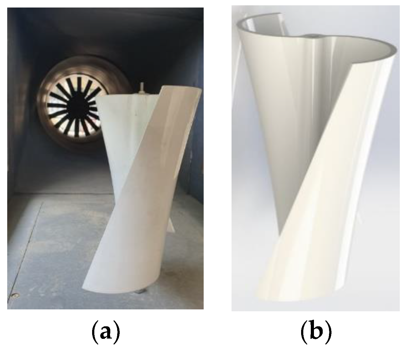
Figure 2.
The artificial neural network structure for objective functions.
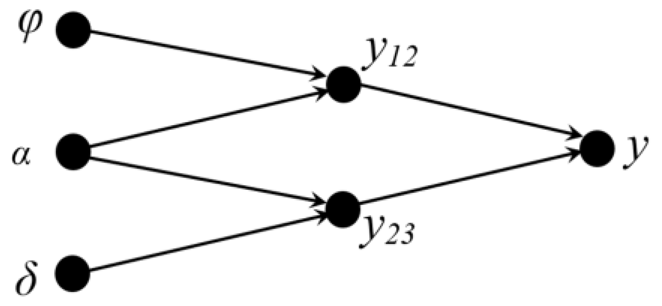
Figure 3.
(a) The non-dominated optimum design points in the plane of 1/CT and 1/Cp (b) plane of 1/Cp and 1/ω, (c) and plane of 1/CT and 1/ω.
Figure 3.
(a) The non-dominated optimum design points in the plane of 1/CT and 1/Cp (b) plane of 1/Cp and 1/ω, (c) and plane of 1/CT and 1/ω.
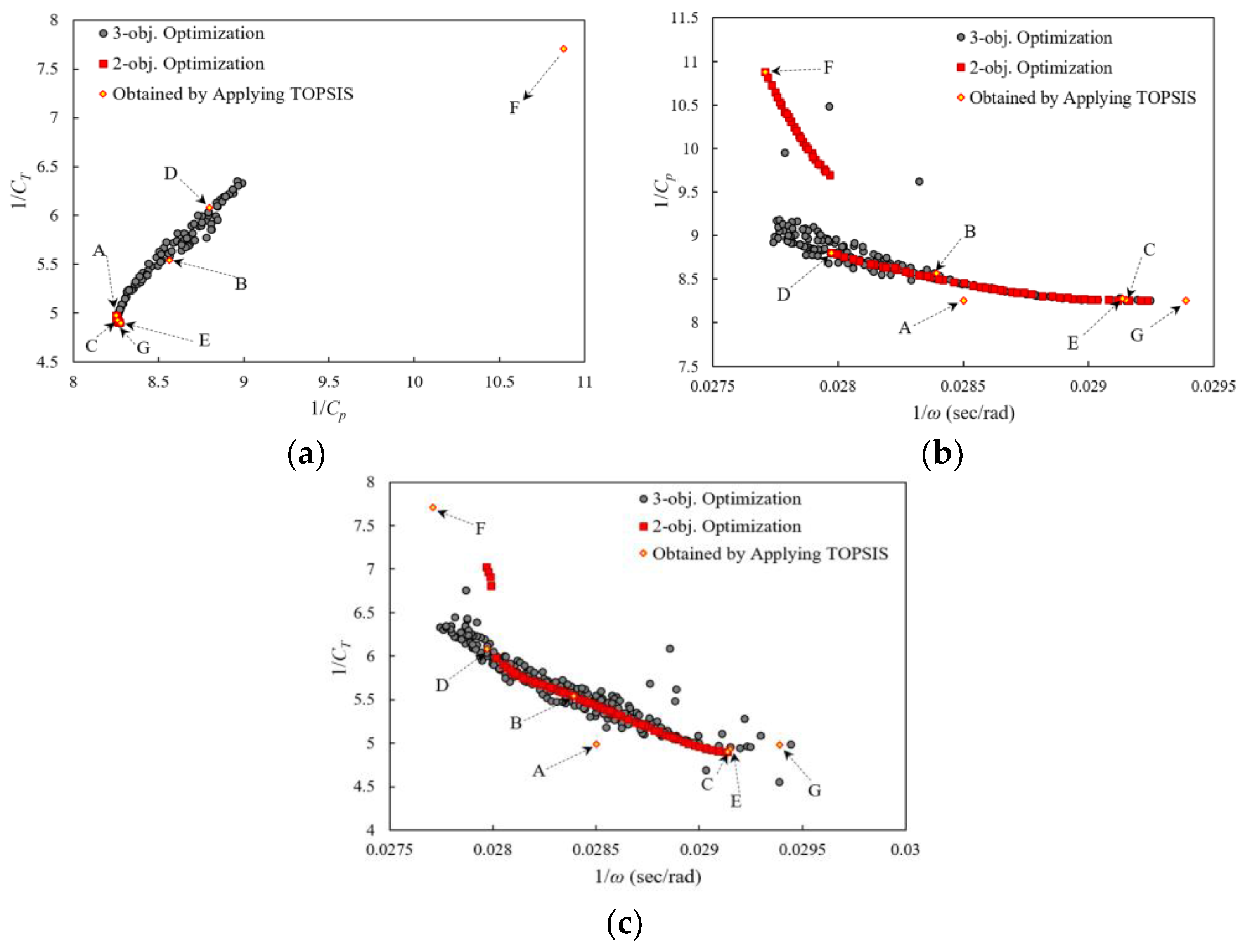
Figure 4.
Comparison between the original and optimized turbines (a) pressure distributions around turbines and (b) the fluid velocity vectors.
Figure 4.
Comparison between the original and optimized turbines (a) pressure distributions around turbines and (b) the fluid velocity vectors.
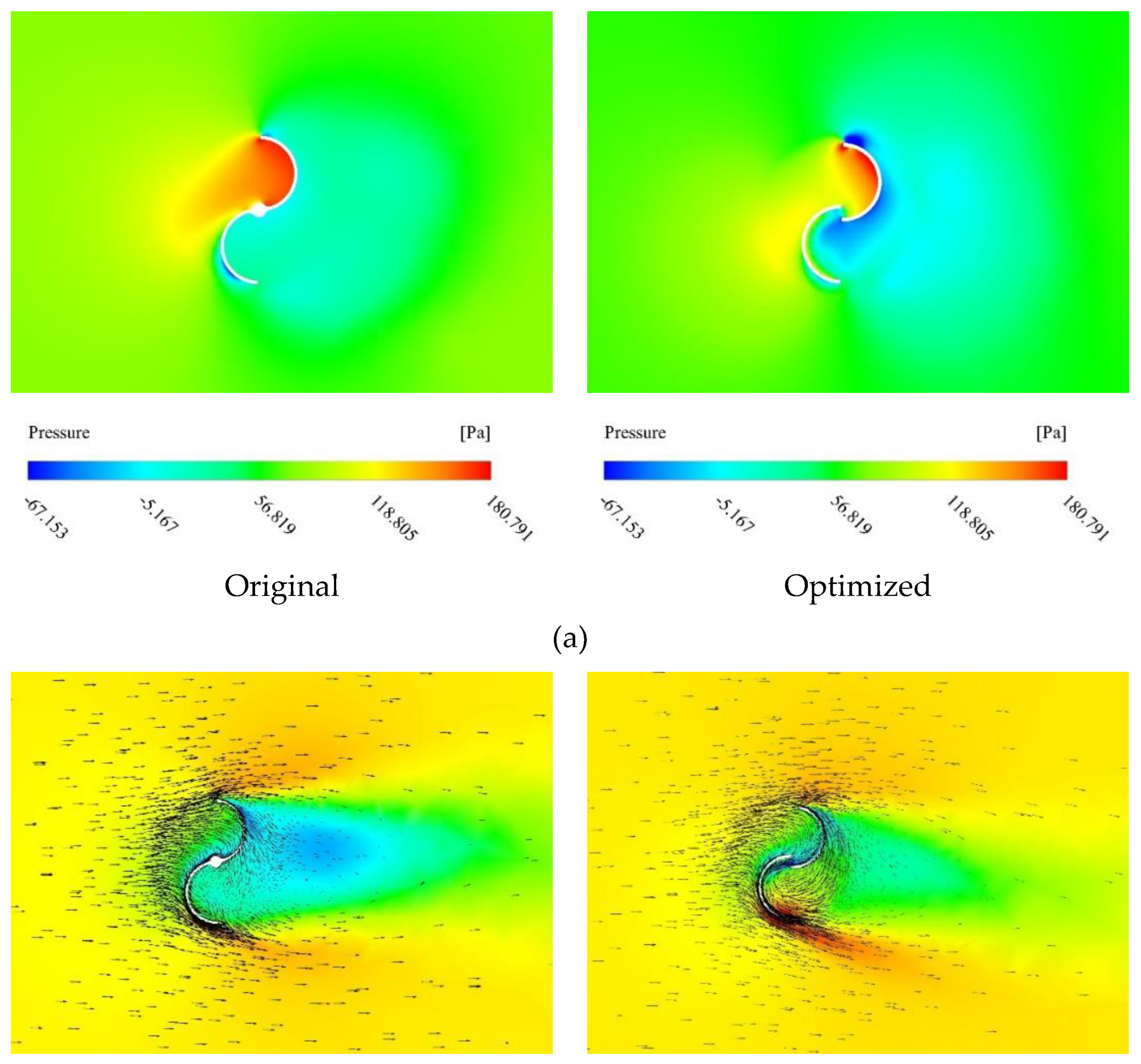
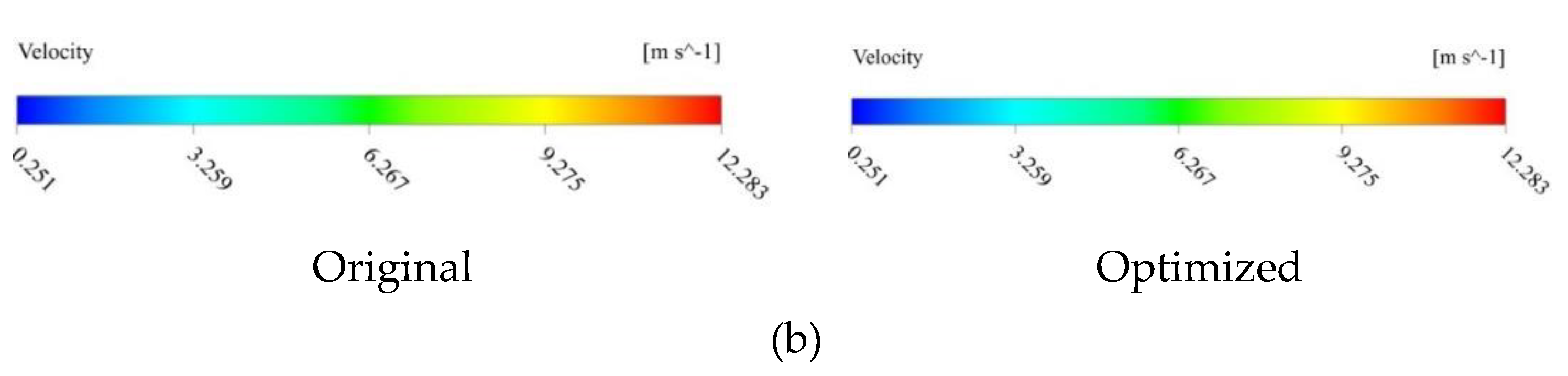
Figure 5.
Three-dimensional model of the inducer [33].
Figure 5.
Three-dimensional model of the inducer [33].
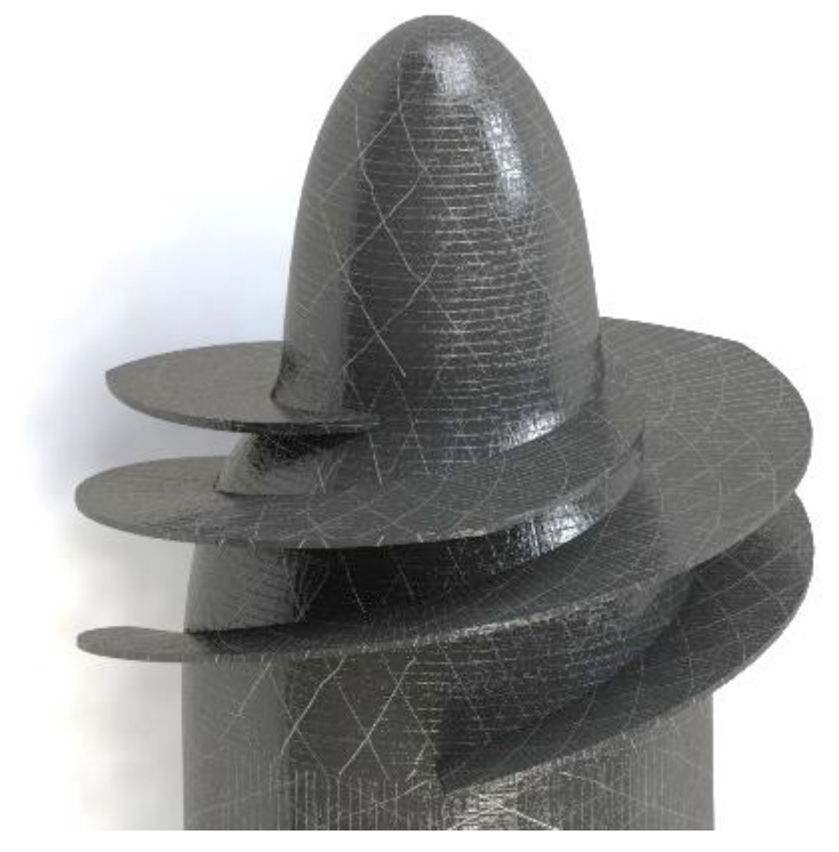
Figure 6.
The artificial neural network structure for objective functions.
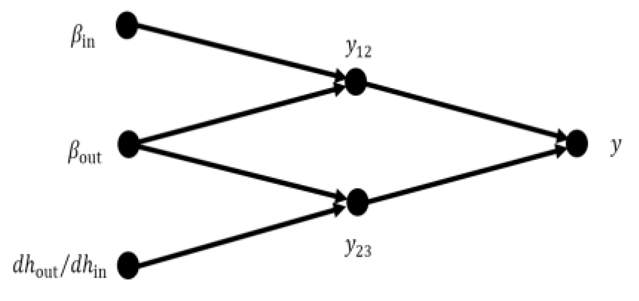
Figure 7.
(a) The non-dominated optimum design points in the plane of NPSHR and 1/η (b) plane of NPSHR and 1/ψ, (c) and plane of 1/η and 1/ψ.
Figure 7.
(a) The non-dominated optimum design points in the plane of NPSHR and 1/η (b) plane of NPSHR and 1/ψ, (c) and plane of 1/η and 1/ψ.
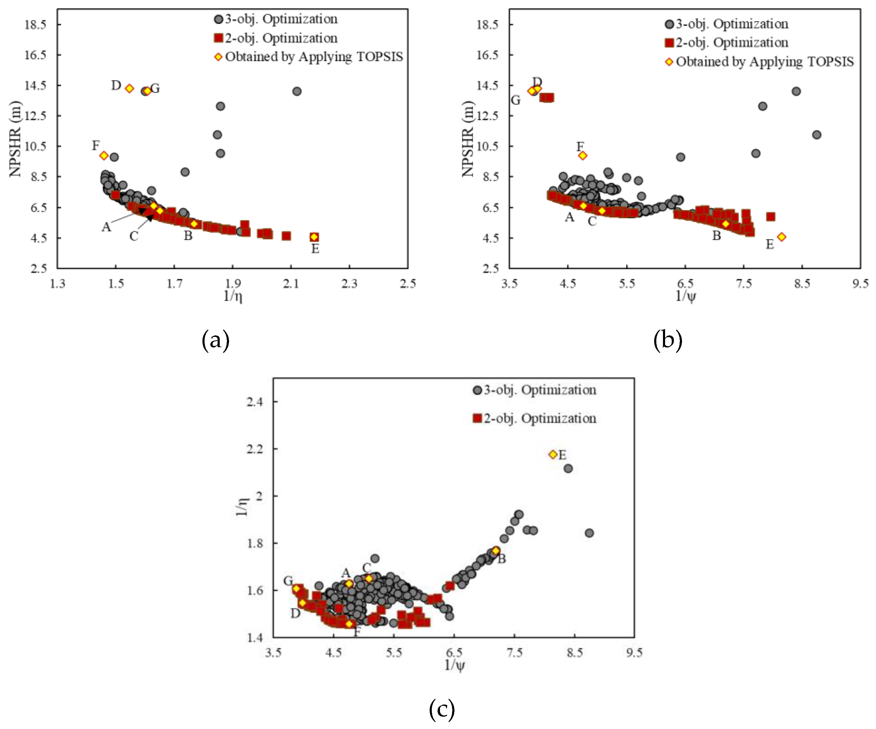
Figure 8.
(a) Comparison between the original and optimized inducers pressure distributions on the pressure side of the blades and (b) the fluid velocity vectors.
Figure 8.
(a) Comparison between the original and optimized inducers pressure distributions on the pressure side of the blades and (b) the fluid velocity vectors.
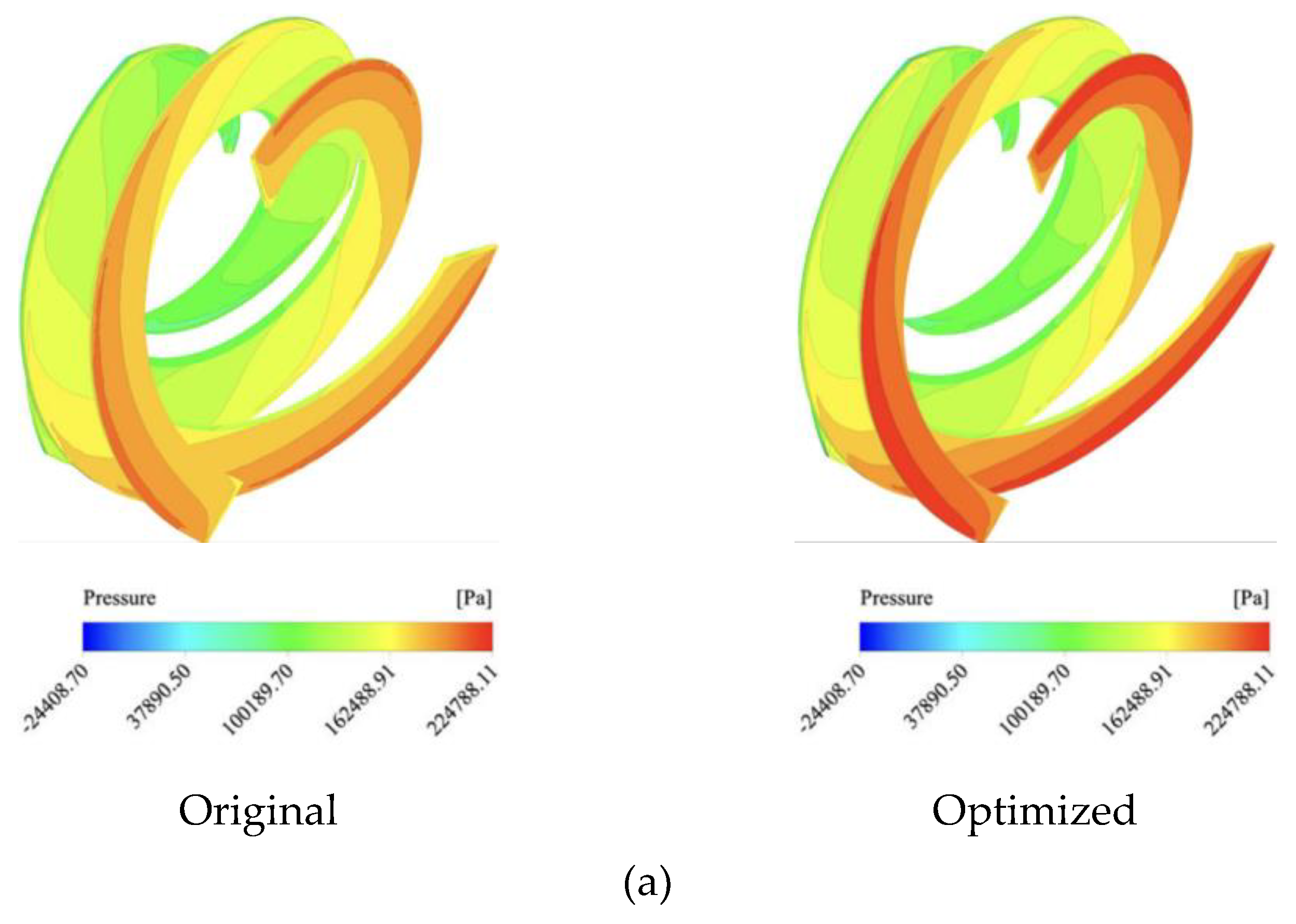
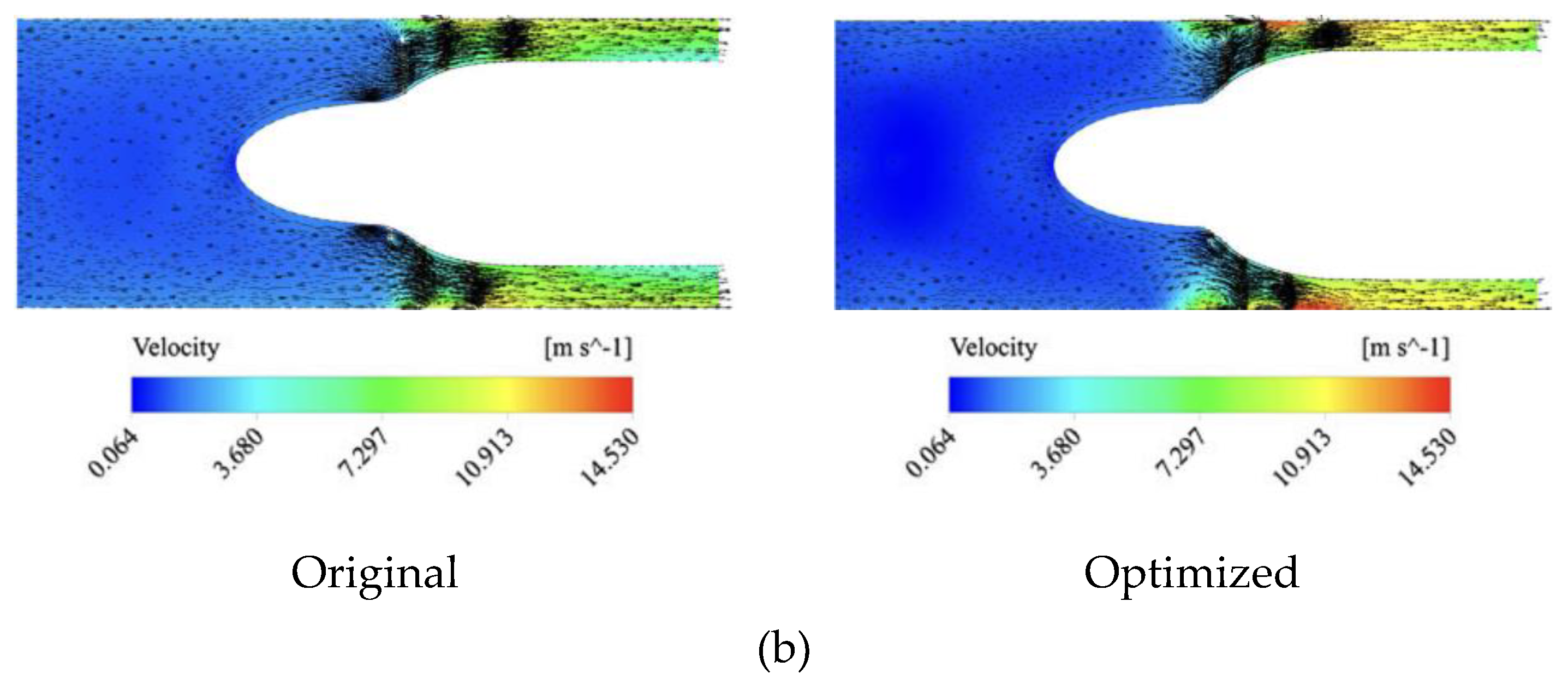

Table 1.
Geometric parameters of the helical rotor.
| Geometric parameters | Value |
|---|---|
| Rotor diameter (D) | 230 mm |
| Rotor height (h) | 162 mm |
| Overlap ratio (δ) | 0 |
| Aspect ratio (α) | 0.7 |
| Blade arc angle | 180˚ |
| Diameter of the blade | 115 mm |
Table 2.
Main design variables and their ranges in performance.
| Design variables | Lower bounds | Upper bounds |
|---|---|---|
| φ | 0 | 60 |
| α | 0.8 | 1.2 |
| δ | 0 | 0.24 |
Table 3.
Samples of numerical results using CFD.
| Input data | Output data | ||||||
|---|---|---|---|---|---|---|---|
| φ | α | δ | Cp | CT | ω | ||
| 1 | 0 | 0.8 | 0 | 0.10735 | 0.142833 | 37.98526 | |
| 2 | 15 | 0.8 | 0 | 0.11875 | 0.161161 | 37.24395 | |
| 3 | 30 | 0.8 | 0 | 0.119894 | 0.165901 | 36.176 | |
| 4 | 45 | 0.8 | 0 | 0.12735 | 0.174851 | 35.6972 | |
| 5 | 60 | 0.8 | 0 | 0.10807 | 0.145388 | 35.0056 | |
| 6 | 0 | 1 | 0 | 0.16414 | 0.154274 | 37.3464 | |
| 7 | 15 | 1 | 0 | 0.11678 | 0.162188 | 36.71072 | |
| 8 | 30 | 1 | 0 | 0.12065 | 0.173663 | 35.112 | |
| 60 | 60 | 1.2 | 0.24 | 0.0935 | 0.130091 | 29.07979 | |
Table 4.
Geometrical and operational characteristics of the inducer [33].
Table 4.
Geometrical and operational characteristics of the inducer [33].
| Design flow coefficient | [--] | 0.059 |
| Number of blades | [--] | 3 |
| Tip radius | mm | 81 |
| Inlet tip blade angle | deg | 83.1 |
| Inlet hub radius (fully-developed blade) | mm | 44.5 |
| Outlet hub radius | mm | 58.5 |
| Axial length (fully-developed blade) | mm | 63.5 |
| Mean blade height | mm | 29.5 |
| Rotational speed | rpm | 2500 |
| Inlet hub radius | mm | 35 |
| Axial length | mm | 90 |
| Diffusion factor | [--] | 0.39 |
| Ratio between the incidence and blade angles | [--] | 0.3 |
| Tip solidity | [--] | 2.03 |
| Hub solidity | [--] | 2.07 |
| Incidence tip angle @ design | deg | 2.07 |
| Outlet tip blade angle | deg | 74.58 |
Table 5.
Design variables and their range of variations.
| Design variables | Lower boundary | Upper boundary |
|---|---|---|
| Inlet tip blade angle (deg) | 79 | 85 |
| Outlet tip blade angle (deg) | 66 | 78 |
| Ratio of the outlet hub radius to inlet hub radius | 1.47 | 1.87 |
Table 6.
Samples of numerical results using CFD.
| Input data | Output data | |||||
| βin (deg) | βout (deg) | dh out/dhin | ψ | η | NPSHR (m) | |
| 1 | 79 | 66 | 1.47 | 0.04041 | 0.173 | 7.473 |
| 2 | 79 | 70 | 1.47 | 0.10702 | 0.463 | 7.669 |
| 3 | 79 | 74 | 1.47 | 0.2144 | 0.653 | 11.161 |
| 4 | 79 | 78 | 1.47 | 0.20437 | 0.635 | 14.218 |
| 5 | 81 | 66 | 1.47 | 0.03863 | 0.171 | 7.703 |
| 6 | 81 | 70 | 1.47 | 0.10568 | 0.459 | 5.964 |
| 7 | 81 | 74 | 1.47 | 0.22064 | 0.659 | 10.834 |
| 8 | 81 | 78 | 1.47 | 0.21039 | 0.636 | 13.821 |
| 9 | 83 | 66 | 1.47 | 0.05801 | 0.208 | 7.675 |
| 10 | 83 | 70 | 1.47 | 0.10813 | 0.467 | 4.352 |
| … | … | … | … | … | … | … |
| 47 | 85 | 74 | 1.87 | 0.16338 | 0.645 | 10.757 |
| 48 | 85 | 78 | 1.87 | 0.12351 | 0.55 | 11.449 |
Disclaimer/Publisher’s Note: The statements, opinions and data contained in all publications are solely those of the individual author(s) and contributor(s) and not of MDPI and/or the editor(s). MDPI and/or the editor(s) disclaim responsibility for any injury to people or property resulting from any ideas, methods, instructions or products referred to in the content. |
© 2024 by the authors. Licensee MDPI, Basel, Switzerland. This article is an open access article distributed under the terms and conditions of the Creative Commons Attribution (CC BY) license (http://creativecommons.org/licenses/by/4.0/).
Copyright: This open access article is published under a Creative Commons CC BY 4.0 license, which permit the free download, distribution, and reuse, provided that the author and preprint are cited in any reuse.


