Submitted:
09 August 2024
Posted:
12 August 2024
You are already at the latest version
Abstract
This paper aims to explore the relationship between airfoil deformation and airfoil aerial-aquatic adaptation. The form of “flexible skin and rigid drive structura” holds immense potential for various applications. In this study, we utilize the B-spline method to parametrically describe the airfoil shape. An airfoil deformation parameterization method is proposed based on the isogeometric method. This method allows us to depict airfoil deformation as the position and displacement of the driving point, enabling an expression of the flexible skin's deformation driven by the internal structure. We utilize the Xfoil application and Gaussian regression method to elucidate the relationship between driving point position and displacement and the airfoil's dynamic performance. Additionally, we employ the Sobol method to assess the sensitivity of the driving point variables to the airfoil's dynamic performance. Our findings indicate that the attack angle of the airfoil exhibits the highest sensitivity index to the airfoil's dynamic performance. Furthermore, variables of the driving point situated at the leading and trailing edges of the lower surface significantly impact the airfoil lift coefficient, those located at the mid-section of the upper surface have a considerable effect on the airfoil drag coefficient.
Keywords:
Deformable airfoil parameterization
; Aerial-aquatic airfoil
; Iso-geometric method
; Sobol analysis
1. Introduction
The Aerial-Aquatic Vehicle (AAV) is a new type of vehicle designed to operate in both water and air [1]. This vehicle has the potential for various applications, including water-air communication relays [2], marine environment monitoring [3], and underwater exploration [4], thanks to its three-dimensional trans-media capability [5]. The AAV rotor system plays an important role in AAV design and manufacturing. However, the current design of AAV rotor systems generally represents a trade-off between water and air performance. For rotor-driven aerial-aquatic vehicles, the use of a single-type rotor does not have sufficient aerial-aquatic compatibility this is because the rotor thrust and torque have an approximately linear relationship with fluid density. A rotor system designed for flying may suffer great resisting moments in underwater conditions. A rotor system designed for submerge navigation may not provide sufficient lift force in air conditions. To adapt to the two media, the rotor blade needs to change the rotor section shape between an aerial high-lift airfoil and an underwater low-drag airfoil. Thus, the study of deformable airfoils is of great significance.
The combination of flexible skin and a rigid driving mechanism is a widely used structural form in the field of deformable airfoils. The flexible skin helps maintain the smooth shape of the airfoil during deformation, while the rigid structure ensures sufficient stability for the airfoil. Woods, etc. introduced a deformed airfoil driven by a spooling pulley, which can bend and deform to change the camber of the airfoil[6]. HEO, etc. designed a deformed airfoil based on cellular materials[7]. This mechanism generates camber deformation of the airfoil through microscopic deformation of the cellular materials. Wang, etc. presented a guide deformation driving mechanism based on a four-bar mechanism[8]. This mechanism can change the leading edge camber of the airfoil to adapt to different flight conditions. Icardi, etc. designed a deformable airfoil based on flexible ribs and memory alloy wire. The wing consists of a sandwich box sub-structure with laminated faces, flexible ribs, and flexible skin[9], a 10° variation of airfoil camber can be obtained.
The design of a flexible skin-rigid drive-type airfoil has been extensively researched, but the deformable airfoil for amphibious use in both water and air environments has not been explored. In an aerial-aquatic rotor system, the characteristics of the motor or engine remain constant. To improve the efficiency of the rotor system in both water and air, the thrust coefficient should be higher and the speed lower than that of a typical rotor when the rotor is in the air. Conversely, when the rotor operates underwater, the torque coefficient should be lower and the speed higher than those of a typical underwater rotor[10]. Therefore, an airfoil designed for amphibious navigation should exhibit a higher lift coefficient in the air and a smaller drag coefficient when submerged. This study aims to establish the connection between airfoil deformation characteristics and its adaptability in water and air. By conducting sensitivity analysis, we can identify the specific deformable elements that can enhance the airfoil's adaptability in water and air.
In this paper, we used the B-spline method to provide a parametric description of the airfoil, using the NACA 0015 airfoil as an example to validate the accuracy of the parametric method. To depict the airfoil's shape changes under actuation, we proposed an airfoil deformation parameterization method based on the isogeometric method. This approach directly employs the B-spline curve of the airfoil as the shape function within the finite element framework to calculate the deformation of the flexible airfoil driven by the rigid structure. In comparison to the finite element method, this approach offers stronger geometric intuition and maintains the airfoil's smoothness in the calculation. Subsequently, we utilized the forced displacement method to characterize the impact of rigid actuation on flexible airfoils. The forced displacement point represents the contact point between the rigid drive and the flexible airfoil, with the displacement denoting the shift of the contact point. We computed the lift drag coefficient of the airfoil under various shapes using the two-dimensional airfoil solving application Xfoil and established a surrogate model of the forced point, forced displacement, and lift drag coefficient of the airfoil via the Gaussian regression method. Finally, we used the Sobol method to calculate the influence of the position and displacement of the driving point on the lift drag coefficient of the airfoil. This work can serve as the groundwork for designing water-air amphibious deformable airfoils.
2. Flexible Airfoil and Deformation Parameterization
The combination of a flexible skin and a rigid drive structure is commonly used in deformable airfoil technology. The flexible skin allows for smooth deformation, while the rigid structure provides the necessary driving force and stability. In Figure 1 (a), (b), and (c), various examples of this type of mechanism are depicted.
The application cases demonstrate that the end of the rigid structure is connected to multiple points on the flexible skin. When the airfoil is deformed, these points move, causing the entire flexible skin to deform. In this paper, the flexible skin and rigid driving structure are simplified as flexible skin and driving points, as illustrated in Figure 1(d). This section describes the airfoil shape using the B-spline method and employs the isogeometric method to analyze the impact of driving point position and displacement on the airfoil. The simplified model is useful for examining how the position and displacement of the driving point influence the dynamic performance of the airfoil.
2.1. The B-spline Method
The B-spline method offers great flexibility, allowing for local control of the curve's shape while maintaining smoothness. The B-spline curve defines the airfoil shape by using a basis function and a set of control points. For a B-spline curve with n+1 control points, it can be described by Equation 1.
where, is the vector of the control point, shown in Equation 2.
is the basic function defined on knot vector U, as shown in Equation 3.
The knot vector is shown in Equation 4.
The curvature of B-spline type curve S can be described as Equation 5.
In Equation 5, the superscripts x and y denote the components of the curve S in the X and Y directions. The subscripts u and uu denote the first and second derivatives of the u, as shown in Equation 6.
2.2. Airfoil Parameterization Example
To assess the accuracy of the B-spline airfoil parameterization method, a numerical example has been established. The initial airfoil chosen is the NACA 0015 airfoil, consisting of 399 scattered points. Two 3-order B-spline curves are utilized to accommodate the upper and lower surfaces of the airfoils. The least-square curve approximation method[12] is utilized to fit the airfoil shape. The fitting is repeated 6 times, using a different number of control points. The number of control points N and fitting errors are listed in Table 1.
The fitting error gradually decreases and converges as the number of control points increases. To ensure fitting accuracy and reduce calculation cost, this paper utilizes a B-spline curve with 15 control points to fit the upper and lower surfaces of the airfoil. The fitting results are depicted in Figure 2.
2.3. Deformation Parameterization Based on the Iso-Geometric Method
The isogeometric method is a type of finite element method that incorporates the concept of isoparametric analysis. In this method, the calculation domain is defined by curves, faces, or volumes composed of spline curves. The shape function is represented by B-spline basis functions, and the variables to be solved are the coordinates of control points. In the isogeometric method, a B-spline curve is used to model the airfoil as a spline curve with elastic potential energy. When the rigid driving mechanism inside the airfoil displaces several points on the spline, the coordinates of the control points are solved to minimize the overall elastic potential energy of the spline curve. These control points' coordinates then represent the shape of the deformed airfoil. This method establishes a relationship between airfoil deformation and the position and displacement of the driving point, aiding in the analysis of the impact of the internal rigid driving mechanism on the airfoil.
2.3.1. Airfoil Deformation Model
In this section, the Euler-Bernoulli beam theory is used to establish the airfoil deformation model. This theory describes the relationship between spline displacement and load, as shown in Equation 7.
The displacement of the spline curve in the Y direction is denoted by p, and w represents the load distributed on the spline. According to Euler-Bernoulli beam theory, K is defined as the product of the elastic modulus and the moment of inertia of the beam. However, since a curve has no moment of inertia, K is defined as the ratio of the curvature change to the bending moment. The elastic potential energy of the spline within the interval can be represented by Equation 8.
Where represents the curvature of the deformed spline curve and represents the initial curvature of the airfoil. The change in curvature caused by deformation can be approximately described by Equation 9 through the Y-direction displacement of the spline curve.
Assuming that the spline deforms only in the Y direction, can be defined as the constant J. p in Equation 9 can be represented by a B-spline as shown in Equation 10.
can be obtained through Equation 6. The 5-point Gauss integral method is used to calculate the elastic potential energy . For k-order B-spline curves, the shape of the spline on the interval [i, i+1] is defined by . Then, equation 8 can be discretized, as shown in Equation 11.
Where, represents the Gauss weight, represents the Gauss point position. When achieves its minimum value, Equation 11 is satisfied.
Equation 11 can be written in a matrix form, as shown in Equation 12.
Where, , represents the second derivative of the basis function corresponding to the control point at the position . Define the term in brackets on the right side of Equation 12 as . is referred to as the element stiffness matrix in finite element methods. In the method proposed in this section, is used to establish a mapping between driving point displacement and spline deformation.
The stiffness matrix D for the entire spline curve can be constructed by combining the stiffness matrices of each node interval, as illustrated in Figure 3.
2.3.2. Forced Displacement Constrain and Driving Point
The effect of a rigid driving structure on flexible skin can be thought of as the way the airfoil changes shape when certain points are forcefully moved. The forced displacement applied to the interval can be described using Equation 13.
After applying constraints, the problem of solving control points becomes a quadratic function extremum problem with constraints. This section employs the Lagrange multiplier method to address this issue. Equation 14 represents the expression for a spline curve under m constraints.
can be written as Equation 15.
In Equation 15, only is non-zero terms. To fix the positions of the leading edge and trailing edge points, the displacement of and should be constrained to 0. and , set to 0, are used to fix the leading edge radius and trailing edge thickness. The control point p can be determined using Equation 12.
2.4. Airfoil Deformation Parameterization Examples
To investigate the impact of forced displacement of the driving point on the airfoil's deformation, this section presents three examples. The initial airfoil used is the NACA 0015 airfoil, and three different driving point positions are applied to the airfoil's lower surface. The parameter settings for the examples can be found in Table 2. The wing deformation for the three examples is illustrated in Figure 4.
The lower surface of the airfoil deforms when the driving point is displaced. By using B-splines and iso-geometric methods for parameterization, we can accurately describe the complex wing deformation while keeping the wing's surface smooth. Changing the position of the driving point allows us to observe how internal rigid driving affects the flexible skin. This analysis helps us understand the impact of airfoil deformation on aerodynamic characteristics before we design the internal drive structure. We can design the driving mechanism based on the driving point's position and displacement characteristics, making the design process for deformable airfoils more straightforward and intuitive.
3. Sensitivity Analysis of Airfoil Deformation on Dynamic Performance
The application of deformable airfoils in water, air, and amphibious scenarios is a new area of study. Many researchers have highlighted the importance of this research in developing propulsion systems that can work efficiently in both water and gas environments. Currently, there is no effective and reliable method for deforming and driving these airfoils. This section analyzes the sensitivity of the airfoil's dynamic characteristics to the position and displacement of the driving point. It also ranks the importance of each design variable to reduce the design space dimensions and improve design efficiency. The study uses the IGA airfoil model to obtain the deformed airfoil and Xfoil to calculate the lift and drag coefficients. To reduce computational costs, a Kriging surrogate model was created to describe the relationship between the driving point position, displacement, and the airfoil's dynamic characteristics. Using the Kriging surrogate model, a Monte Carlo sampling method was used to gather data for Sobol sensitivity analysis, as portrayed in Figure 5.
3.1. The Dynamic Calculation
The Xfoil application is used for airfoil lift and drug coefficients. Xfoil uses a high-order panel method and a fully-coupled viscous/inviscid interaction method to evaluate drag, boundary layer transition, and separation[11]. This airfoil design system has proven to be a powerful and useful tool for subcritical airfoil design. The parameters used in Calculation are shown in Table 3.
3.2. Kriging Surrogate Model
The Kriging surrogate model is created in three steps. This involves sampling the design space, calculating the performance function for each sample, and then determining the weighting coefficients of the design variables. If the optimization problem has only one design variable, the first step in creating a proxy model for the performance function is to sample the design space in multiple dimensions, resulting in a matrix that describes the set of sample points.
The Kriging surrogate model is a form of interpolation that involves computing performance functions for each sample point and then linearly interpolating them.
To calculate the weighting coefficients, the unknown function is considered as a concrete implementation of a Gaussian stationary stochastic process. This process can be described as follows.
The Kriging model is used to estimate the true performance function by determining the best weighting coefficients for the interpolated performance function with minimal mean square deviation. The Lagrange multiplier method is used to derive the matrix representation of the Kriging surrogate model.
where , R is the relative matrix.
where r(x) is the relative vector.
The following related functions R are used in this article
Where x, is any two sets of design parameters. is the Gaussian exponential model.
3.3. Sensitivity Analysis with the Sobol Method
The Sobol method is a widely recognized sensitivity analysis technique used within the probabilistic framework. It's particularly adept at handling the interactions of multiple variables within nonlinear systems, making it valuable in engineering applications. In a model with m variables in the input, if the number of N model inputs is available, N model inputs can be obtained through the surrogate model, as depicted in Equation 24.
Equation 22 can be written in decomposition form, as shown in Equation 23.
In the Sobol method, the variance of the values on the right side of equation 23 is computed. The ratio of the variance of a single variable to the variance of the overall system output is known as the first-order sensitivity index of that variable. The second-order sensitivity index is used to quantify the combined influence of two input variables on the system output. Equation 24 presents the first-order sensitivity index of the i-th variable and the second-order sensitivity index of the i-th and j-th variables.
Where,
The study focuses on analyzing the sensitivity of the lift coefficient and drag coefficient of an airfoil concerning the position of the driving point and the vertical displacement of the driving point, and the angle of attack.
- The ranking of the influence of input variables on dynamic performance.
- When the driving point is located in different intervals, the influence on dynamic performance is different.
- The influence of driving point position and driving point displacement on dynamic performance.
- The difference of influence when the driving point is on the upper and lower surfaces of the airfoil.
The airfoil has three driving points on its upper and lower surfaces, and the angle of attack of the airfoil ranges from 0° to 12°. The system has 7 input variables and 2 output variables. To distinguish between the driving points on the upper and lower surfaces, a superscript is added to the driving point variable. "u" indicates that the driving point is located on the upper surface, and "l" indicates that the driving point is located on the lower surface. 1500 samples were generated using the Monte Carlo sampling method, and the lift and drag coefficients of the airfoils in both air and underwater conditions were obtained using the Kriging surrogate model. Sensitivity analysis was conducted separately for the two output variables. The input variables and their value ranges are shown in Table 4. Figure 6 shows a clear geometry meaning of each variable and their value space. Before sensitivity analysis, the value space of all variables was normalized to [0, 1].
4. Discussion
The sensitivity analysis is conducted on the input parameters using the range of parameters shown in Table 4. The sample is generated using a Monte Carlo sampling method. The dynamic performance is obtained through the Kriging surrogate model, mentioned in section 3.2.
4.1. First-Order and Total Sensitivity Discussion
The first-order sensitivity and total effect of each variable are evaluated using Equation 24. First-order effects refer to the impact of each input parameter on the corresponding output parameter. The total effect includes the interaction between input variables and other variables.
The lift coefficient sensitivity of each variable is shown in Figure 7(a). Figure 7(b) shows the lift coefficient sensitivity of parameters without the attack angle, for clarity. The lift coefficient of an airfoil is significantly influenced by the angle of attack , with a first-order influence index of 0.7307. Considering the interaction with other variables, the total effect of the attack angle is 0.786. The displacement of driving points near the leading and trailing edges of the airfoil on its lower surface, namely and , has a substantial impact on the lift coefficient. The first-order influence of and is 0.054 and 0.073. On the upper surface, the displacement near the middle of the airfoil has a greater influence on the lift, which has a first-order index of 0.015. The sum of the first-order index of variables on the upper surface is 0.0343. The sum of the first-order index of variables on the lower surface is 0.1397. However, although the index of the upper surface is low, their total index is much higher than their first-order index. This indicates that those variables have a greater interaction with other variables. This indicates that the deformation of the airfoil's lower surface is more important than the upper surface. The sum of the first-order index of position variables is 0.00296, and the sum of the displacement variables is 0.174. This indicates that the driving stroke plays a more important role than the driving position when the design aim is to improve the lift coefficient.
The drag coefficient sensitivity of each variable is shown in Figure 8. Figure 8 indicates that the attack angle and are the most influential parameters, with first-order index of 0.320 and 0.409. The sum of the first-order index of the variable of the upper surface is 0.5305, while the sum of the lower surface variables is 0.0344. This indicates that the upper surface deformation is more important when the design is to decrease the drag coefficient underwater. In addition, as the same with the lift coefficient, the position variables has little influence on the drag coefficient.
4.2. Interaction Effects Discussion
The second-order sensitivity index reflects the interaction influence with other variables. The second-order sensitivity index of each variable to the lift coefficient is shown in Figure 9. Figure 9 shows that the attack angle has a strong interaction influence with the displacement variables of the airfoil's upper surface(0.028 with , 0.025 with , 0.025 with ). The interaction between displacement variables of the airfoil’s lower surface has a relatively low influence on the lift coefficient. Although the first-order index of the position variables is low, as mentioned in section 4.1, the interaction influence with the attack angle is relatively large. In comparison, the variables of the upper surface have a larger interaction influence than the variables of the lower surface.
The second-order sensitivity index of each variable to the drag coefficient is shown in Figure 10. Unlike the lift coefficient, the interaction between the angle of attack and other variables has little effect on the drag coefficient. However, the interaction between displacement variables is large. The interaction of a variable combination that one on the upper surface and one on the lower surface is particularly large( and , -0.024, and , -0.022). This phenomenon shows that the smoothness of the airfoil has a great influence on the drag coefficient. The driving points on the upper and lower surfaces, particularly at the leading and trailing edges, have a greater second-order influence as they affect the sharpness or smoothness of these edges.
The angle of attack is the most important variable for changing the lift drag coefficient of the airfoil. When designing an amphibious deformable airfoil, it is crucial to consider changing the angle of attack first. For a deformed airfoil intended to improve the lift coefficient, the deformation of the lower surface of the airfoil is more important than that of the upper surface. The connection between the driving mechanism and the flexible skin should be close to the leading or trailing edge of the airfoil. On the other hand, for a deformed airfoil designed to improve the drag coefficient, the deformation of the upper surface of the airfoil is more important, and the connection point between the driving mechanism and the flexible skin should be close to the leading edge of the airfoil. Additionally, the design of the deformation driving mechanism should account for the influence caused by the change in attack angle, considering the second-order sensitivity of the airfoil attack angle and each driving point to the lift coefficient.
5. Conclusions
The objective of this paper is to establish the relationship between airfoil deformation characteristics and its adaptability in water and air. Through sensitivity analysis, the study identifies the specific deformation elements that enhance the airfoil's adaptability in water and air. The airfoil is parameterized using the B-spline method. The deformation energy of the airfoil's upper and lower surfaces is determined using the isogeometric method as a reference, and airfoil deformation is described by applying driving points. Xfoil is utilized for calculating the lift and drag coefficients of the airfoil in both water and air. Additionally, a Kriging surrogate model is created using the Gaussian regression method. The sensitivity analysis is carried out within the Sobol framework, using the position and displacement of the driving points as input variables and the lift and drag coefficients of the airfoil as output variables. The study's conclusions are as follows.
- The parameterization method based on IgA theory for Airfoil is able to accurately describe the original airfoil and also represent a wide range of airfoil deformations. The local control characteristics of the B-spline help maintain smoothness in the airfoil before and after deformation. This method is useful for showing how the driving structure affects the deformation of flexible skin.
- The angle of attack of an airfoil is a crucial factor in altering the dynamic performance of a rotor whether it operates underwater or in the air. When designing a morphing rotor for amphibious navigation, the deformation of the angle of attack should be the primary consideration.
- The placement of the control points on the lower surface of the airfoil significantly affects the lift coefficient of the airfoil. When designing a modified airfoil to improve the lift coefficient, it's important to take into account the deformation of the lower surface.
- The positioning of the pressure points on the upper surface of the airfoil significantly affects the drag coefficient. When designing a modified airfoil to minimize drag, it's important to take into account the deformation of the upper surface.
Conflicts of Interest
The authors declare no conflicts of interest.
References
- Esakki, B. Ganesan, S. Mathiyazhagan, S. et al., Design of amphibious vehicle for unmanned mission in water quality monitoring using internet of things. Sensors, 2018, 18, 3318. [Google Scholar] [CrossRef]
- Yao, G.C. Li, Y.Z. Zhang, H.Y. et al., Review of hybrid aquatic-aerial vehicle (HAAV): Classifications, current status, applications, challenges and technology perspectives. Progress in Aerospace Sciences, 2023, 139, 100902. [Google Scholar] [CrossRef]
- Koparan, C. Koc, A.B. Privette, C.V. et al., Adaptive water sampling device for aerial robots. Drones, 2020, 4, 5. [Google Scholar] [CrossRef]
- Lu, D. Xiong, C.K. Zhou, H.X. et al., Design, fabrication, and characterization of a multimodal hybrid aerial underwater vehicle. Ocean Engineering, 2021, 219, 108324. [Google Scholar] [CrossRef]
- Hou, T.G. Jin, D.Z. Gong, Y.Y. et al., Frontier technology analysis and future prospects of aquatic un-manned aerial vehicle. Science and Technology Review, 2023, 41, 5–22. (In Chinese) [Google Scholar]
- Woods, B.K. Friswell, M.I. Multi-objective geometry optimization of the fish bone active camber morphing airfoil. Journal of Intelligent Material Systems and Structures, 2016, 27, 808–819. [Google Scholar] [CrossRef]
- Heo, H. , Ju, J. Kim, D.M. Compliant cellular structures: Application to a passive morphing airfoil. Composite Structures, 2013, 106, 560–569. [Google Scholar] [CrossRef]
- Bao, Q.W. Andrea, D.R. Design optimization and testing of a morphing leading-edge with a variable-thickness compliant skin and a closed-chain mechanism. Chinese Journal of Aeronautics, 2024, 37, 285–300. [Google Scholar]
- Icardi, U. Ferrero, L. Preliminary study of an adaptive wing with shape memory alloy torsion actuators. Materials and Design 2009, 30, 4200–4210. [Google Scholar] [CrossRef]
- Tan, Y.H. Chen, B.M. Motor-propeller matching of aerial propulsion systems for direct aerial-aquatic operation. 2019 IEEE/RSJ International Conference on Intelligent Robots and Systems (IROS), Macau, China, 2019, pp. 1963–1970.
- Nie, M. Zhu, T. Li, Y. NURBS interpolator with minimum feedrate fluctuation based on two-level parameter compensation. Sensors, 2023, 23, 3789. [Google Scholar] [CrossRef] [PubMed]
- Fakhari, S.M. Mrad, H. Aerodynamic shape optimization of NACA airfoils based on a novel unconstrained conjugate gradient algorithm. Journal of Engineering Research. [CrossRef]
Figure 1.
Diagraph of flexible skin and rigid driving mechanism (a) Diagraph of the Fishbone[6] (b). Diagraph of cellular airfoil[7] (c). Morphable Leading edge with 4 bar mechanism[8] (d). Diagraph of a flexible skin and driving point.


Figure 2.
Diagraph of NACA 0015 airfoil and control points.
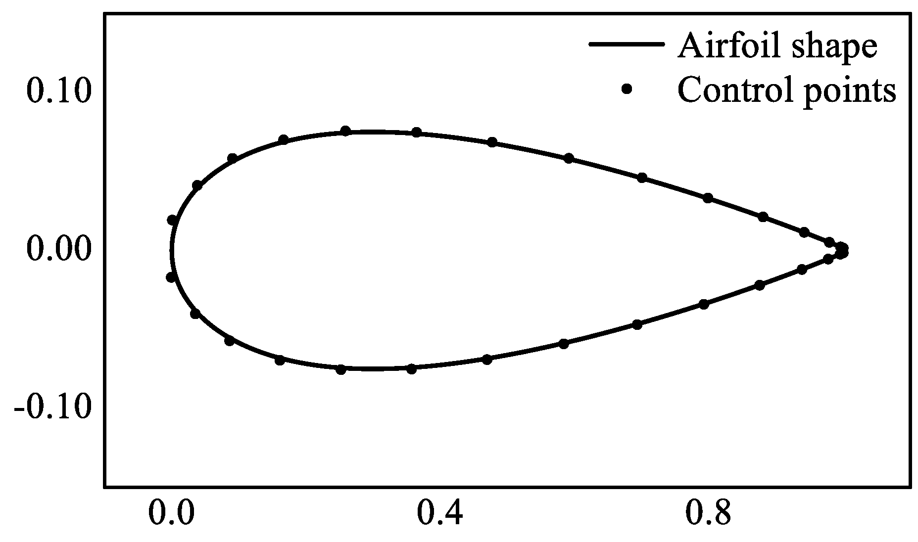
Figure 3.
Matrix construction.
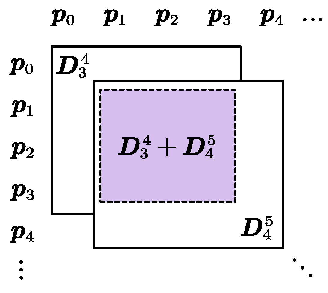
Figure 4.
Diagraph of the original and deformed airfoil in example (a) Example 1 (b) Example 2 (c) Example 3.
Figure 4.
Diagraph of the original and deformed airfoil in example (a) Example 1 (b) Example 2 (c) Example 3.
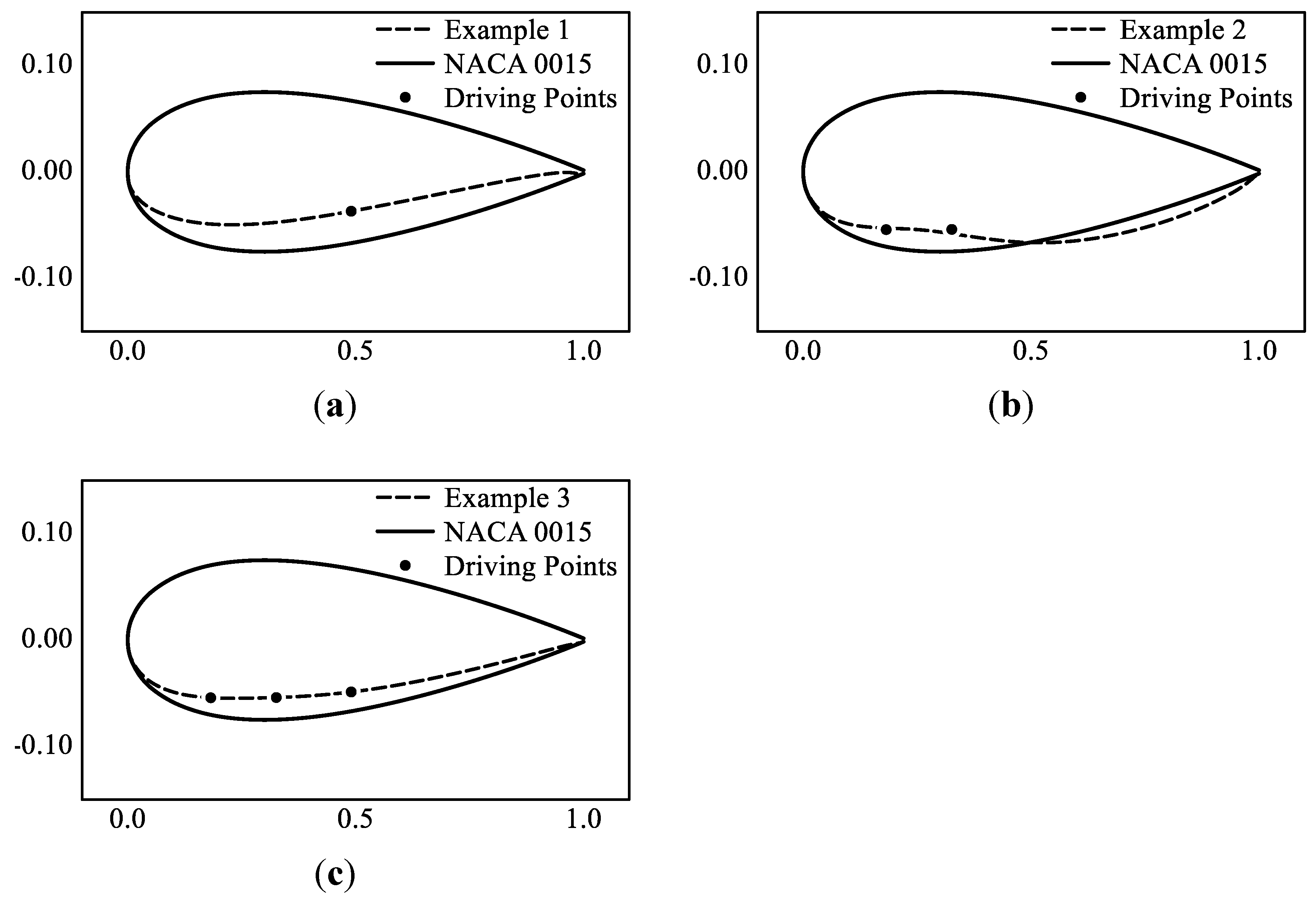
Figure 5.
Flowchart of sensitivity analysis of airfoil deformation.
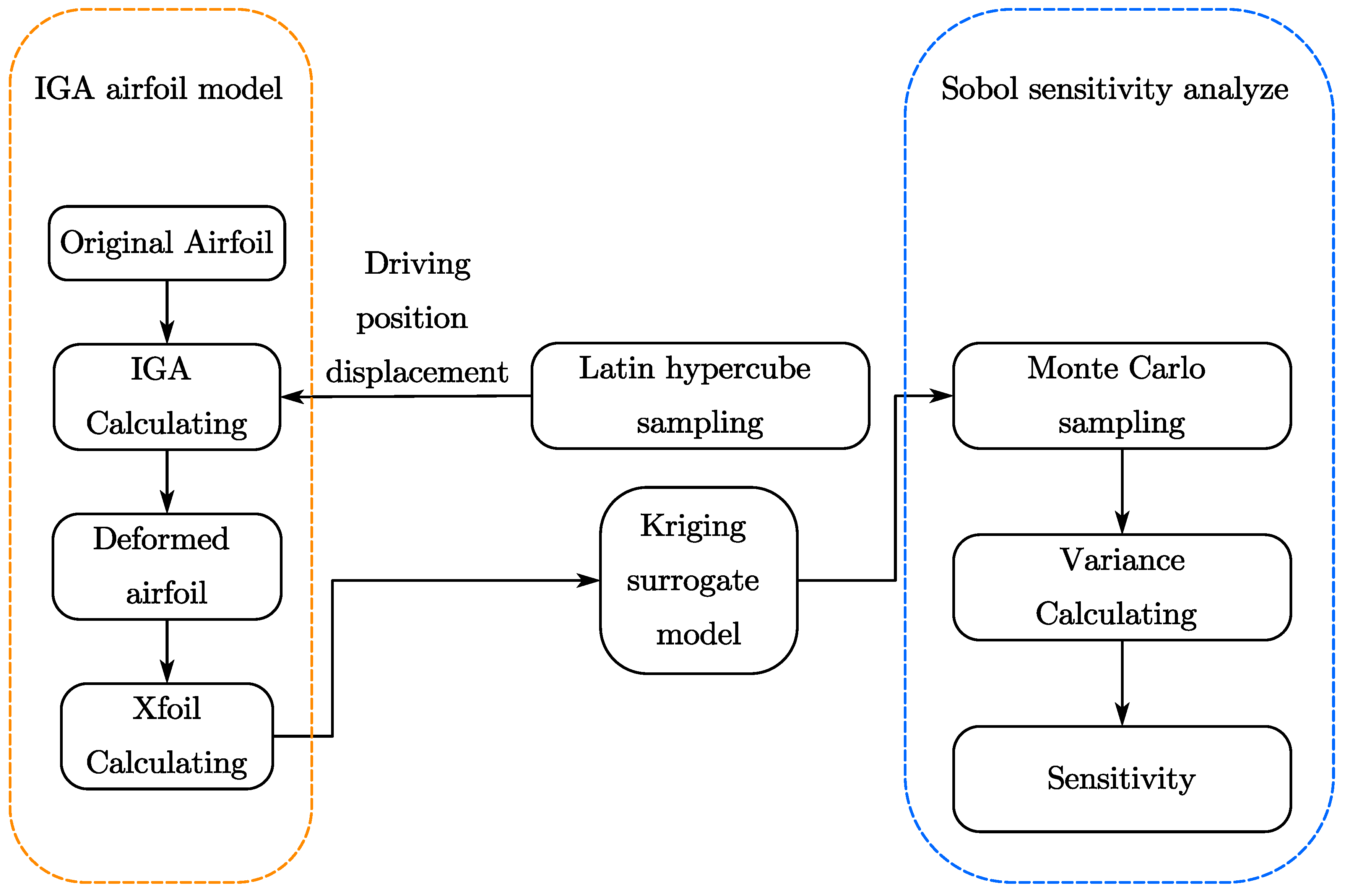
Figure 6.
Diagraph of variable definition.
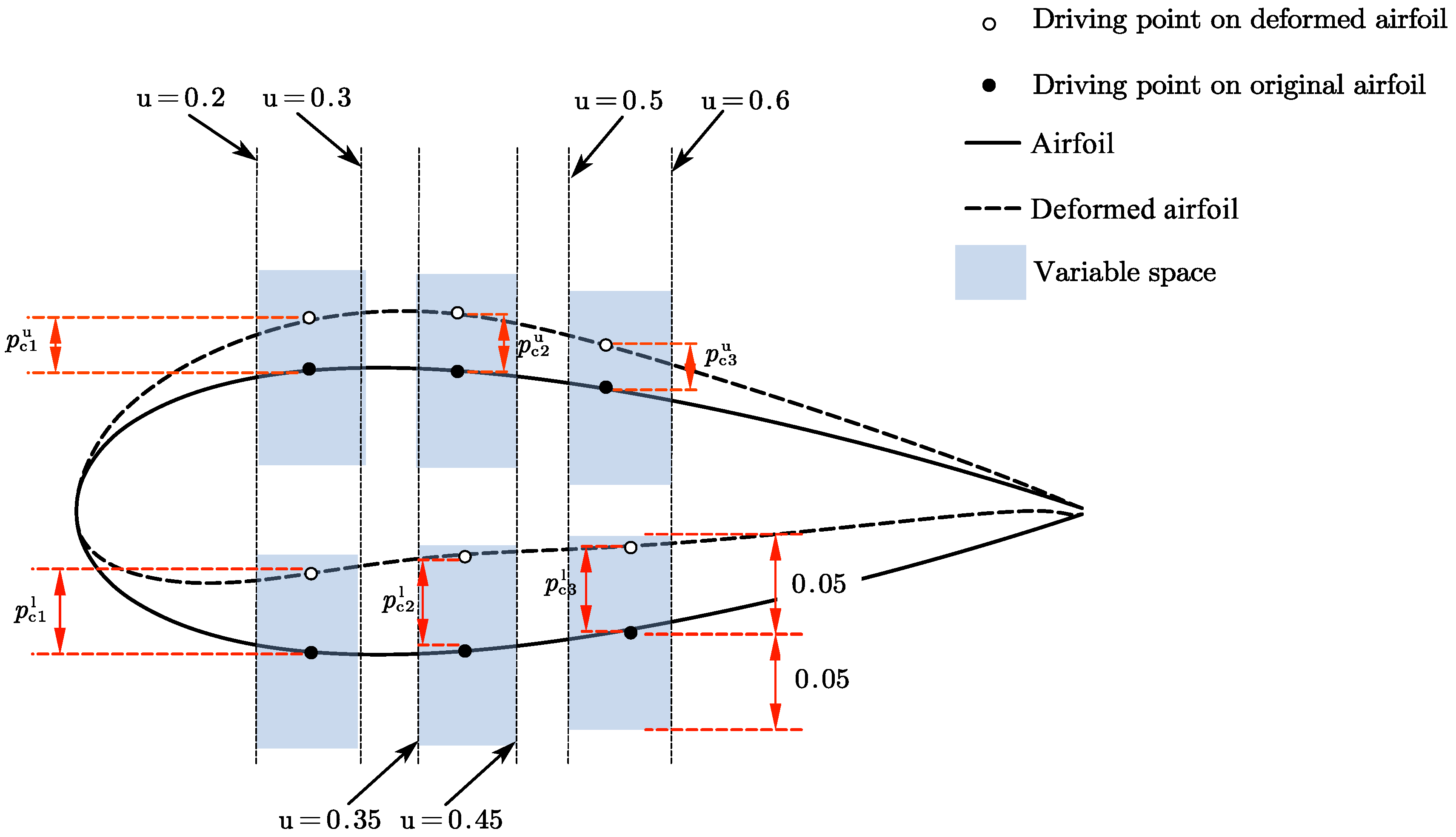
Figure 7.
First-order index and total effect on lift coefficients (a) Bar chart of all variables (b) Bar chart of variables without the attack angle.
Figure 7.
First-order index and total effect on lift coefficients (a) Bar chart of all variables (b) Bar chart of variables without the attack angle.
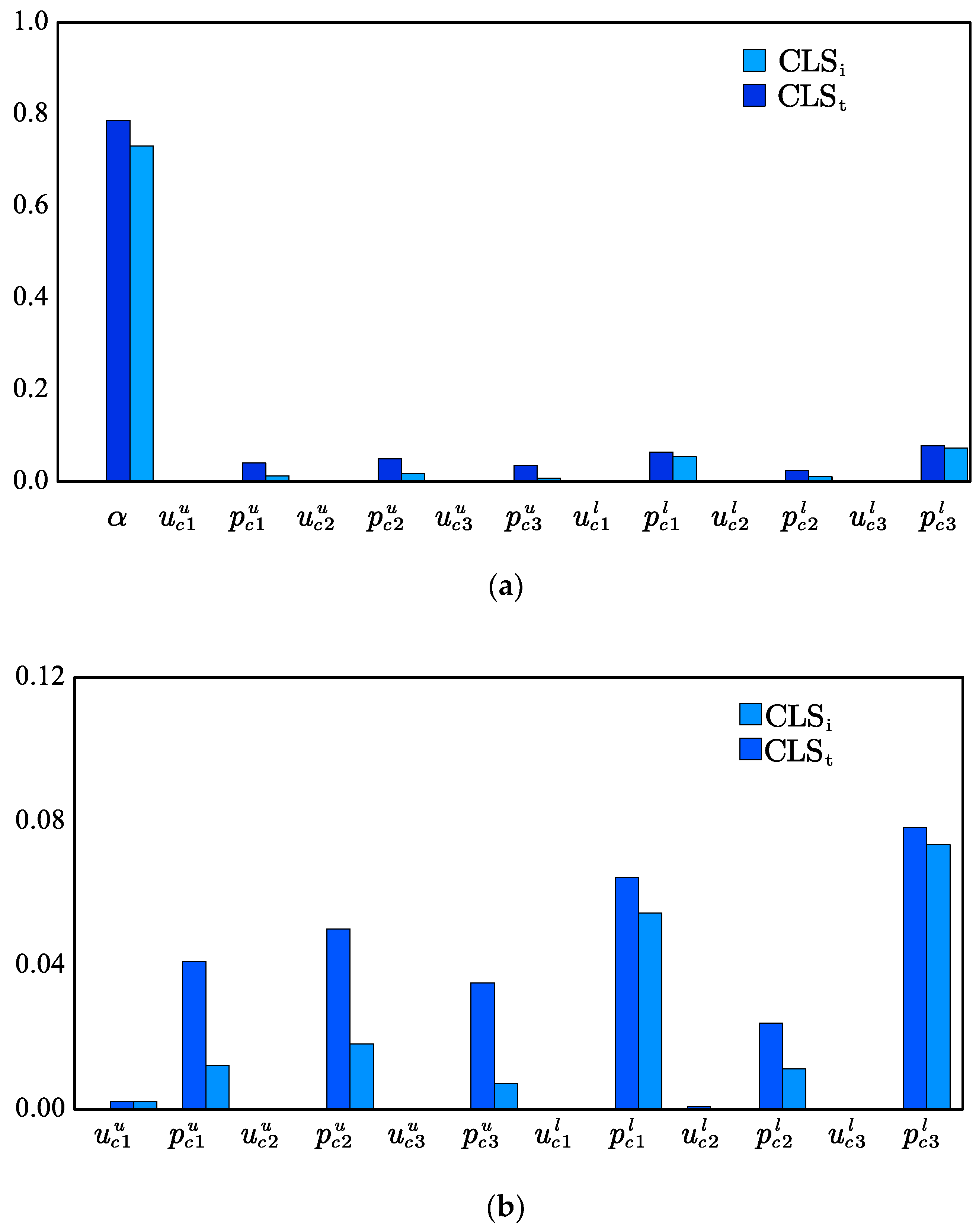
Figure 8.
First-order index and total effect on drag coefficients.
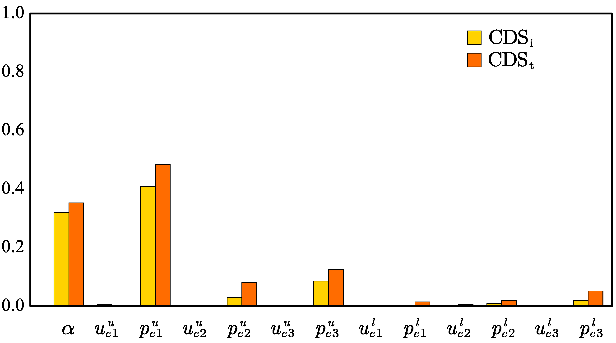
Figure 9.
Second-order sensitivity index on lift coefficient.

Figure 10.
Second-order sensitivity index on drag coefficient.
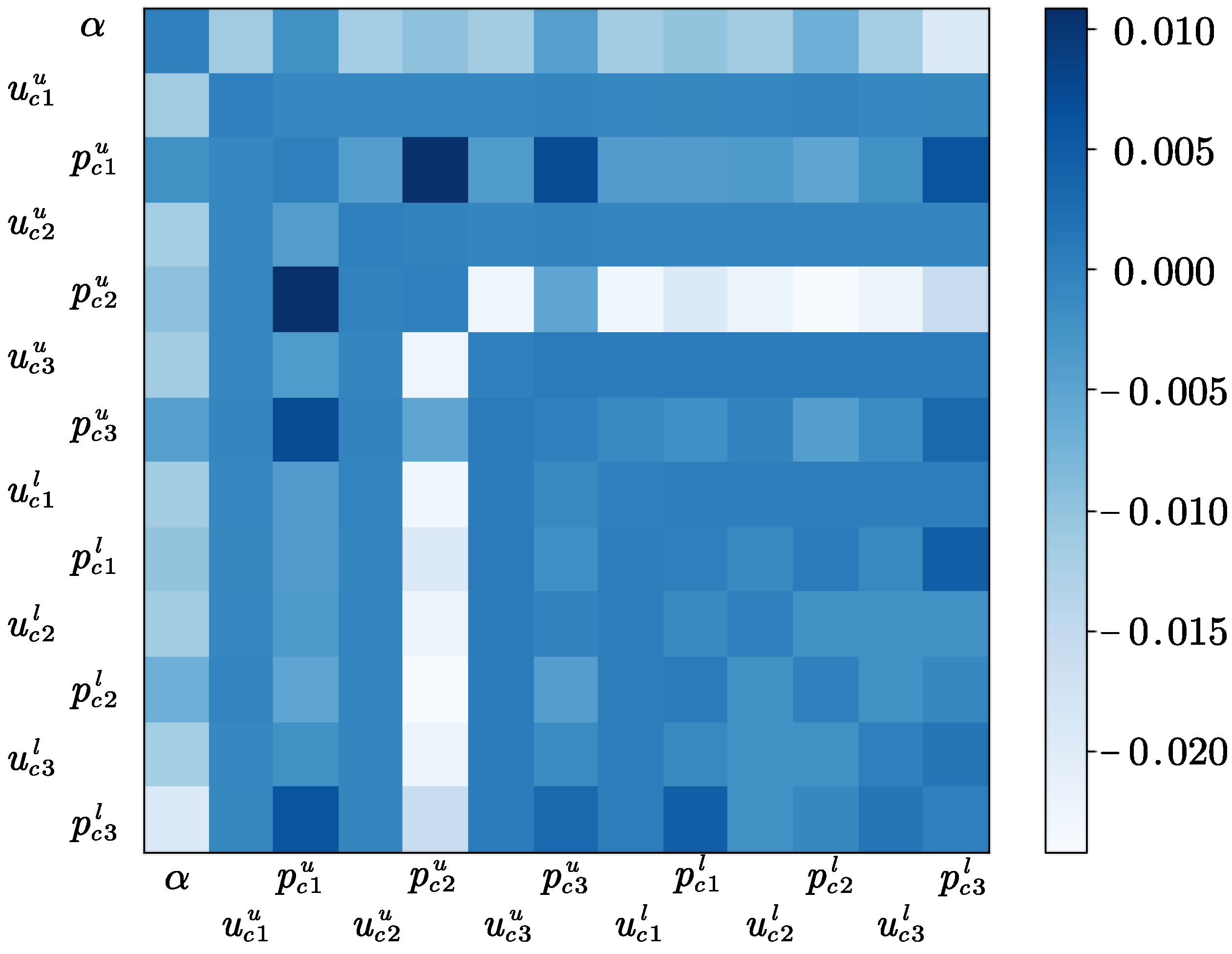

Table 1.
Control points number and fitting errors.
| N | 6 | 10 | 15 | 20 | 25 | 30 |
|---|---|---|---|---|---|---|
| Max error | 0.01005 | 0.00244 | 0.000489 | 0.000328 | 0.000256 | 0.000204 |
Table 2.
Example parameters.
| Original airfoil | ||||
|---|---|---|---|---|
| Example 1 | NACA 0015 | 0.5, 0.05 | -- | -- |
| Example 2 | NACA 0015 | 0.2, 0.01 | 0.34, 0.02 | -- |
| Example 3 | NACA 0015 | 0.2, 0.01 | 0.34, 0.02 | 0.36, 0.023 |
Table 3.
Calculation parameters.
| Renold number | Mach number | |
|---|---|---|
| Aerial condition | 210000 | 0.09 |
| Aquatic condition | 170000 | 0.0017 |
Table 4.
Variables to be studied.
| Variable | Value space | Meaning |
|---|---|---|
| [0, 12] | Airfoil attack angle | |
| [0.2, 0.3] | Upper surface driving point 1 position | |
| [0.35, 0.45] | Upper surface driving point 2 position | |
| [0.5, 0.6] | Upper surface driving point 3 position | |
| [-0.05, 0.05] | Upper surface driving point 1 displacement | |
| [-0.05, 0.05] | Upper surface driving point 2 displacement | |
| [-0.05, 0.05] | Upper surface driving point 3 displacement | |
| [0.2, 0.3] | Lower surface driving point 1 position | |
| [0.35, 0.45] | Lower surface driving point 2 position | |
| [0.5, 0.6] | Lower surface driving point 3 position | |
| [-0.05, 0.05] | Lower surface driving point 1 displacement | |
| [-0.05, 0.05] | Lower surface driving point 2 displacement | |
| [-0.05, 0.05] | Lower surface driving point 3 displacement |
Disclaimer/Publisher’s Note: The statements, opinions and data contained in all publications are solely those of the individual author(s) and contributor(s) and not of MDPI and/or the editor(s). MDPI and/or the editor(s) disclaim responsibility for any injury to people or property resulting from any ideas, methods, instructions or products referred to in the content. |
© 2024 by the authors. Licensee MDPI, Basel, Switzerland. This article is an open access article distributed under the terms and conditions of the Creative Commons Attribution (CC BY) license (https://creativecommons.org/licenses/by/4.0/).
Copyright: This open access article is published under a Creative Commons CC BY 4.0 license, which permit the free download, distribution, and reuse, provided that the author and preprint are cited in any reuse.


