
Submitted:
02 August 2024
Posted:
05 August 2024
You are already at the latest version
Abstract
The implementation of morphing wing mechanisms holds promise in enhancing aircraft perfor-mance, as indicated in current literature. The Clean Sky 2 AirGreen 2 European project is currently conducting ground and wind tunnel tests to validate innovative studies on morphing wing structures. The project aims to showcase the effectiveness of these morphing architectures on a potentially flying demonstrator at true scale. This article describes design methodology and struc-tural testing of a scaled morphing flap structure capable of 3 different morphing modes required for low-speed (take-off/landing) and high-speed (cruise) conditions. A significant scale factor of 1:3 was selected to enhance the importance and relevance of the wind tunnel test campaign. Geometrical scaling to the real flap prototype was deemed impractical due to limitations associated with scaling the embedded mechanisms and actuators responsible for shape changing. Static analyses were performed using the finite element method to address the most critical loads determined through three-dimensional CFD analysis. The Finite Element (FE) analysis results were briefly outlined, and comparisons were drawn between the obtained results and the empirical data collected during the structural test. Good correlations were observed between the results and numerical predictions, encompassing static deflections under applied loads and elastic deformations. Consequently, the modeling approaches utilized during the design and testing phases were considered highly suc-cessful. Therefore, based on the results extrapolated from simulations under ultimate load condi-tions relevant to the wind tunnel test campaign, the scaled flap prototype was deemed suitable for testing.
Keywords:
Morphing structures
; Smart aircraft
; Morphing flap
; Adaptive systems
; Intelligent systems
; Finger-like ribs
; Mechanical systems
; Large airplanes
; Wind tunnel tests
; Large-scale morphing architectures
; Computational Fluid Dynamics (CFD) analysis
; Variable camber airfoil
1. Introduction
The concept of adjusting the aircraft’s geometry to optimize aircraft performance across various flight regimes has been a consistent objective in aviation history. Traditional approaches have involved the utilization of movable components like ailerons, slats and flaps which are prevalent solutions for extending the operational capabilities of aircraft [1]. Despite their benefits, these solutions have presented challenges such as increased weight due to the required actuators and disturbances to aerodynamic surfaces. Consequently, alternative design approaches have been carefully examined, with one notable approach being the morphing-oriented design [2]. This design approach focuses on developing actuation techniques capable of achieving significant and smooth geometric changes. The morphing mechanism offers advantages by facilitating substantial changes in curvature without relying on traditional slats and flaps, which can lead to complexities related to issues like gap overlap and deflections. In recent years, numerous studies have been carried out to examine the best approaches for these technologies and to discover the most efficient solutions for morphing technologies [3].
In the aviation industry, high-lift systems have been widely adopted on aircraft wings to effectively manage lift and drag forces during critical phases like take-off and landing. However, the conventional approach to wing control surfaces, including leading edge slats and trailing edge flaps, typically relies on discrete, rigid structural components that are mechanically manipulated through hinges and linkages to achieve the necessary adjustments in wing geometry. This traditional method significantly amplifies system complexity and contributes to an overall increase in structural weight. Furthermore, it is important to highlight that the existence of flap slots and their accompanying fairings has been recognized as a significant source of both airframe noise and aerodynamic drag [4].
Numerous instances of manned aircraft design can be observed throughout aviation history, particularly from the 1910s and 1920s. In the first instance [5], a patent was granted for kinematic systems designed to alter the external configuration of the leading and trailing edges of the wing. The second example introduced a design that allowed for the self-adaptation of the profiles of biplanes and triplanes [6]. A notable advancement was achieved with the F-111, which featured a wing capable of continuously adjusting its leading and trailing edge cambers. This aircraft underwent an extensive testing program, the outcomes of which remain significant in the field of adaptive aeronautical structures. The enhanced capabilities in loitering, diving, and maneuvering were clearly demonstrated, ultimately showcasing the potential of this innovative technology [7,8]. Additional research conducted at the Research Laboratory in Active Controls, Avionics, and Aeroservoelasticity Laboratory (LARCASE) at École de technology supérieure (ÉTS) has focused on the advancement of morphing winglet and horizontal tail systems specifically for the CRJ-700 aircraft [9,10,11] and the Cessna Citation X business aircraft [12,13].
In the past few decades, there has been significant and encouraging advancement in
In recent decades, there has been significant and encouraging advancement in morphing technologies including innovative morphing mechanisms and concepts, the development of novel methods for actuation, and the utilization of smart materials. The belt-rib concept was developed and used at German Aerospace Centre (DLR) within framework of the Adaptive Wing project. In its fundamental configuration, the belt-rib structural framework comprised a closed shell, referred to as the belt, reinforced by in-plane stiffening elements called spokes. Typically, these spokes were connected to the belt through solid-state hinges [14]. Experimental studies have demonstrated the feasibility and potential of the the belt-Rib concept as a promising solution for airfoil shape control and geometric adaptability [15].
Another morphing trailing edge (TE) concept was developed and tested in the DARPA/AFRL/NASA Smart Wing program to demonstrate the feasibility of utilizing actuator concepts based on smart materials for the creation of control surfaces within adaptive wing structures that are devoid of gaps and hinges. The project aimed to improve the aerodynamic and aeroelastic performance of military aircraft. The flexible skin-flexcore concept consisted of three main elements: an outer skin made of elastomeric silicone material, a flexible honeycomb structure, and at its core, a central leaf spring [16].
Wind tunnel experiments demonstrated that the smart trailing-edge control surfaces could be tilted to angles of up to 20 degrees in less than 0.33 seconds. These tilting movements were tested with various spanwise shapes, encompassing both uniform and nonuniform configurations such as linear and quadratic ramps, sine waves, and cosine waves. Daynes and Weaver [17] improved this study by a new flap construction. Their construction consisted of a combination of components: an upper skin fabricated from compliant carbon fiber-reinforced plastic (CFRP), a flexible honeycomb core, and a lower skin characterized by its flexibility, composed of silicone material. The analysis results indicated that the morphing flap can achieve a 30% reduction in tip deflection while still generating an equivalent change in lift when compared to a conventionally hinged plain flap with an identical chord length [18].
Another novel camber morphing concept known as fish bone active camber (FishBAC) was introduced by Woods and Friswell [19]. This concept exhibited the capacity for significant, dual-direction adjustments in camber and had potential to implement in various applications, including fixed-wing aircraft, helicopters, tilt-rotor aircraft, and wind turbines.
The design integrated four fundamental components that collectively facilitate a robust and adaptable camber morphing mechanism. These elements included a flexible backbone with stringers, a pre-tensioned elastomeric matrix composite (EMC) skin, an opposing tendon drive system coupled with a locking spooling pulley to prevent backdrive; and a ‘rigid’, non-morphing main spar.
Hetrick et al. conducted a study on FlexSys Inc.‘s Mission Adaptive Compliant Wing (MACW), a project that involves a morphing trailing edge concept integrated and flight tested on a large manned aircraft. The morphing flap demonstrated enhanced aerodynamic performance through flight tests. [20]. The MACW’s ability to reduce separated flow and drag across various lift conditions was highlighted, achieved by enabling smooth trailing edge deflections through a servo mechanism within the wing’s structure. Flight tests at high speeds and altitudes showed the MACW’s potential for endurance flight applications, with a morphing rate of 30° per second at Mach 0.4. The study projected fuel savings of up to 15% for aircraft with MACW-like wings, emphasizing reduced actuation force and power requirements compared to conventional flaps. The research suggests that morphing wing concepts, like the MACW, could offer promising alternatives to traditional control surfaces [21].
After conducting additional investigations, FlexSys Inc. developed the advanced FlexFoil™ as a transformative control surface capable of achieving notable deflections between -9° and +40° by leveraging distributed compliance enabled by a unique internal mechanism. The company posits that incorporating FlexFoil™ in extended-range aircraft could result in a reduction of drag by 5% to 12%, consequently yielding significant enhancements in fuel efficiency. Furthermore, FlexFoil™ guarantees a smooth and continuous integration with the rest of the wing structure even during deflection [22]. The FlexSys technology was implemented and subjected to flight testing on NASA’s Gulfstream-III Subsonic Research Aircraft Testbed (SCRAT) as part of the Adaptive Compliant Trailing Edge (ACTE) project. During the testing, the SCRAT aircraft was equipped with the FlexSys morphing trailing edge in place of the conventional aircraft flaps. The primary goal of this evaluation was to assess the aerodynamic efficiency and noise reduction capabilities of the compliant morphing trailing edge [23].
The Flexsys Mission Adaptive Compliant Wing represents a significant advancement in enhancing aircraft performance and efficiency. However, the integration of MACW systems in commercial aviation necessitates compliance with certification requirements set forth by aviation regulatory authorities such as the Federal Aviation Administration (FAA) and the European Union Aviation Safety Agency (EASA). Nonetheless, the certification process faces challenges related to structural integrity, material fatigue, safety standards, and regulatory compliance. The utilization of advanced materials and flexible structures demands a reevaluation of traditional testing methodologies. It is imperative to ensure the longevity and fatigue resistance of these novel materials across diverse operational scenarios.
The distinction between military and civil matters is essential due to the notable differences in challenges and requirements within each domain. Consequently, the solutions and obstacles that need to be tackled vary significantly. In the civil sector, additional differentiations emerge based on the scale of the aircraft, which can vary from large jets to commuter planes and general aviation. These classifications can be further segmented into specific types such as tourism, acrobatic, and ultralight aviation, each with distinct characteristics and considerations.
Despite significant efforts, the scientific and technological community has begun to question why morphing technology has not yet reached a level of maturity suitable for practical application, particularly in the context of larger aircraft. At this point, the European community has allocated significant resources to various research initiatives aimed at elevating the technology readiness level of morphing structures. Notably, Clean Sky [10] emerges as the most ambitious aeronautical research program ever undertaken in Europe focusing on smart morphing structures. The primary goal of this program was to pioneer the advancement of innovative technologies capable of substantially improving the environmental performance of aircraft and air transportation, ultimately leading to the production of quieter and more fuel-efficient airplanes. In line with this objective, a novel full-scale prototype of a morphing flap was successfully engineered for potential integration into the upcoming generation of eco-friendly regional aircraft. Initially, the research efforts were centered on a specific segment of the flap component as the foundational stage of this advancement.
The initial phase of the research involved conducting computational fluid dynamic analyses, which effectively demonstrated the feasibility of achieving enhanced CLmax values and a increased stall angle through the active control of the flap’s camber, even at relatively small flap deployment angles [24,25,26]. Remarkably, the results indicated that a conventional double-slotted flap could potentially be substituted with a single-slotted flap incorporating camber morphing characteristics while maintaining comparable effectiveness.
To direct aerodynamic investigations towards viable structural alternatives, an initial identification was made of a morphable design for the flap ribs. A segmented arrangement, resembling fingers, was contemplated as a physical means of realizing the transition from the original airfoil shape to the desired configurations [27,28]. In Figure 1 [29,30] each rib was envisioned as comprising four sequential blocks (B0, B1, B2, B3), linked by hinges positioned along the airfoil camber line (A, B, C). It was noteworthy that Block B0 remained securely anchored to the flap track mechanism, while the remaining blocks retained the freedom to pivot around the hinges on the camber line. This distinctive arrangement effectively transformed the camber line into a flexible chain of successive segments. The introduction of linking rod elements and rotation amplification mechanisms (L, M1 and M2), strategically hinged on non-adjacent blocks, facilitated controlled rotation of the camber line segments, enforcing specific gear ratios to attain the desired shapes.
These components established a one-degree-of-freedom (1-DOF) system for each rib: inhibiting the rotation of any block hinders the ability to alter the shape, while activating an actuator to move any block results in a synchronized motion across all other blocks. The transfer of rib kinematics to the overall trailing edge structure was accomplished using a multi-box layout (Figure 2). In this structural arrangement, each box was conceived with a single-cell configuration defined along the span by corresponding blocks from consecutive ribs, and along the chord by longitudinal stiffening elements, including spars and/or stringers. Four rotary actuators, controlled separately, were installed within the box to enable morphing capabilities.
2. Motivation of the Study
Following promising outcomes achieved in the Clean Sky program, an initiative was launched to further investigate multipurpose adaptive structures. Clean Sky 2, the continuation of Europe’s most significant aviation research and innovation initiative to date, was formally inaugurated in 2014 by the European Commission to satisfy society’s expectations and compete on a global scale by developing efficient and ecologically friendly aircraft solutions. One of the most important aspects of the Clean Sky 2 project is establishing a strong and efficient collaboration with the European Aviation Safety Agency (EASA) and signing a Memorandum of Cooperation (MoC). EASA is responsible for the potential certification of Clean Sky technologies. The collaboration encompasses various elements, including mitigating risks and showcasing the viability of novel concepts and technologies introduced within the Clean Aviation initiative, advancement of industry norms, development of innovative certification approaches and methods for aircraft and systems designs, and progression of regulatory frameworks in alignment with other regulatory bodies and the International Civil Aviation Organization (ICAO) [31].
Clean Sky 2 is home to a plethora of new and upcoming research initiatives, and they go far beyond the typical industry examples seen in areas like cabin technology, production, maintenance, and hybrid propulsion. The Clean Sky 2—Airgreen 2 initiative investigated an innovative multi-functional morphing wing technology to improve the aerodynamic properties of subsequent turboprop regional aircraft along their entire trajectory.
The electromechanical configuration of the morphing flap system is an attractive alternative in the context of this research scenario. While smart materials technology has been applied to shape-change systems in numerous studies and has contributed to progress in this domain, its unsuitability for aviation applications is due to its high power consumption and demand for a robust power system.
The primary goal was to optimize aircraft performance across various flight conditions, specifically aiming to reduce aircraft emissions during the program’s second phase. In this context, a groundbreaking system was devised to elevate both the high lift capabilities and aerodynamic efficiency during the cruise phase of a standard 90-seat aircraft. This improvement was achieved through the innovative technique of in-flight camber morphing of the wing flaps. The recently introduced morphing design concept was developed to support three different morphing modes, adapting dynamically to the requirements of specific flight conditions.
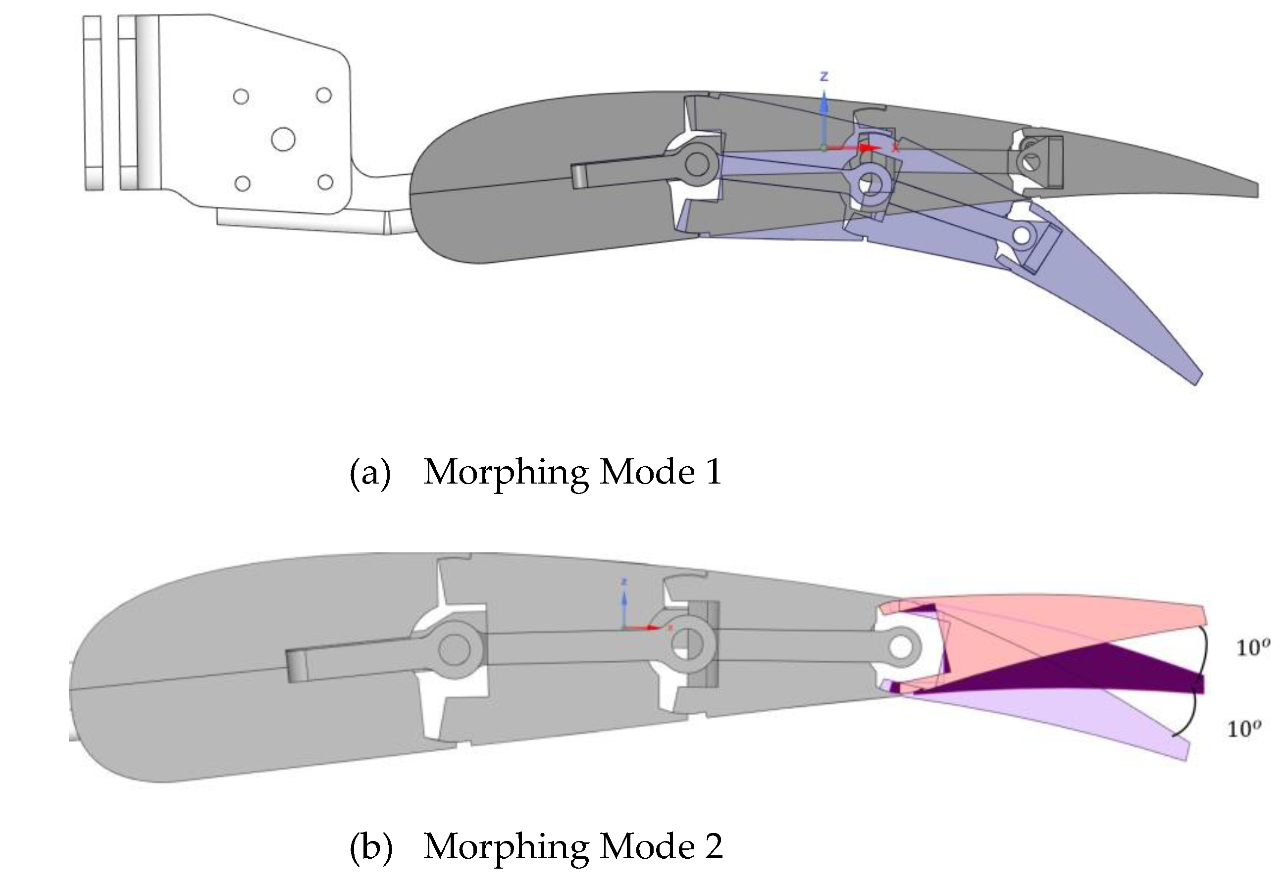
Morphing mode 1: camber morphing of the entire cross-section of the wing flap. (Figure 4a)
Morphing mode 2: deflection of +10°/-10° (upwards/downwards) in the flap tip segment, spanning from 90% to 100% of the local chord. (Figure 4b)
Morphing mode 3: the flap tip is divided into three distinct tabs along the span. These tabs are deflected both upwards and downwards differentially during the cruise, each within the range of +/-10°. This implementation is designed to introduce aerodynamic twist and facilitate load control at higher speeds. (Figure 4c)
The mentioned smart structure undertook a thorough design and validation process that included both ground and wind tunnel experiments. This allowed for the different morphing modes needed for low speed (take-off/landing) and high speed (cruise) situations. While the primary goal of the wind tunnel tests was to validate the computational fluid dynamics (CFD) results and show that the scaled device worked as intended under simulated operating conditions, the primary objective of the ground tests was to show that the full-scale system worked as expected and was robust when prepared for flight. Fo the ground test a true-scale device was manufactured. The wind tunnel test-article was instead chosen with a large scale factor of 1:3 and Mach numbers close to those expected in flight were tested.
The wind tunnel model required a new morphing architecture since it was not feasible to scale the embedded mechanisms and actuators to enable shape transition. This design was created to meet the needs of dimensional scaling, endure the weights in aerodynamic testing, safely withstand the relevant aerodynamic loads expected during the tests, and accurately imitate the shape transition capabilities of the full-scale flap.
The development of this sophisticated wind tunnel model was previously documented in research [32] that focuses on the design processes and technological solutions used.
Initially, computational fluid dynamics (CFD) studies were conducted to assess the most extreme load scenarios predicted during the wind tunnel experiment. This led to the development of a novel mechanical layout for the model, which allowed for rapid shape changes thus preventing unacceptably long dead time during the test for the modification of the flap aerodynamic configuration. To ensure the tests were safe, particularly under the high-speed conditions, and to demonstrate the model’s robustness, in-depth structural evaluations were finally conducted [32].
A total of 18 test scenarios were generated using three different Mach levels, two distinct angle of attack values, and three various flap settings/shapes. Researchers conducted a structural study to evaluate the system’s safety in the wind tunnel and identified the two most important scenarios. The structural analysis was carried out into Ansys® environment by referring to pressure distribution evaluated by CFD. Von Mises stress distribution and maximum displacement across the flap were both determined. The results demonstrated that all the components and joints had a large margin of safety against plastic deformation and failure under the most severe load conditions expected during the tests [32].
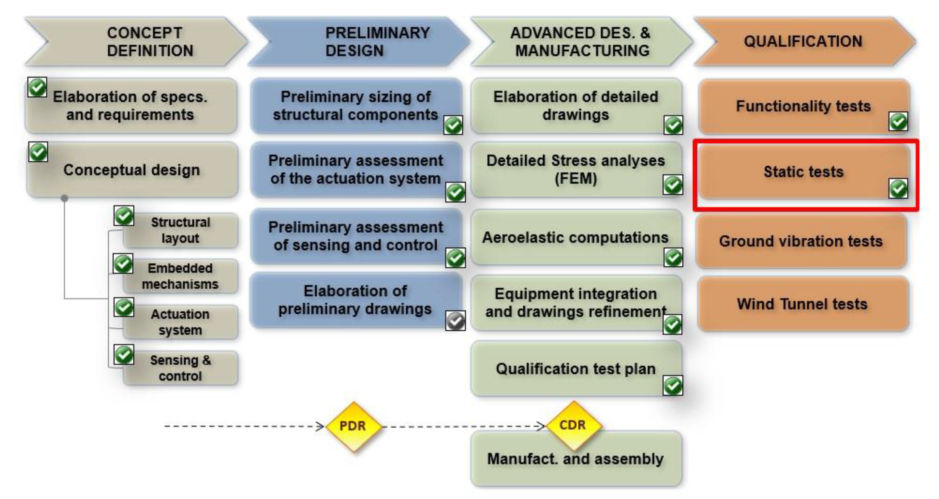
In Figure 3, the project work packages are detailed, illustrating the progress made thus far. Sicim et al. explained the details of the design characteristics and computational fluid dynamics (CFD) assessment of a novel morphing flap system [32]. During the design phase, the following factors were carefully considered: ensuring that solutions meet the standards of the aeronautics market, including aspects such as certification, safety, operational reliability, costs, and maintenance processes. Additionally, feasibility was demonstrated to meet the criteria of the aircraft manufacturing industry.
The focus of this journal is on the work package highlighted within the red box, with a particular emphasis on the validation of the design and production processes for the wind-tunnel test article. This discussion is complemented by experimental static tests conducted to verify the effectiveness of the structural and mechanical approaches implemented. It is crucial to validate structural analyses through testing to confirm the suitability of the morphing flap structure for wind tunnel experiments, its ability to endure the aerodynamic forces encountered in the wind tunnel, and its capacity to maintain functionality under such conditions.
Figure 3.
Work packages for scaled wind tunnel model.
3. Mechanical Layout of the Morphing Flap Wind Tunnel Model and Static Test Targets
The wing-flap model, intended for wind tunnel validation, has a scale of 1:3, relevant dimensions are provided in Table 1. Both the inner and outer flap models were conceived using the same conceptual layout that was carefully developed, considering the most extreme operating load conditions that were expected throughout the testing [32]. The model’s overall structure was specifically defined for the inner segment, with the intention of indirectly applying a similar structure to the outer segment.
The true-scale flap, as demonstrated by the wind-tunnel model, successfully replicated the shape alterations of the flap in accordance with three distinct morphing modes. Morphing mode 1 resulted in a comprehensive variation in the camber of the flap airfoil and was intended for activation solely during take-off and landing phases (low-speed conditions) in practical applications. This activation is designed to improve the high-lift performance of the aircraft, facilitating steeper initial climb and descent trajectories while also contributing to noise reduction during these phases. This characteristic offers a wider range of airfoil configurations for every flap setting, potentially simplifying the mechanisms involved in deploying the flaps. Consequently, actuation tracks could be incorporated within the airfoil of the wing, removing the necessity for external fairings. Conversely, the morphing modes 2 and 3 relate to the final section of the flap in the chord-wise direction and are designed to be operational solely during cruise conditions when the flap is in its stowed position (Figure 4). These modes facilitate load control functionalities aimed at improving the lift-to-drag ratio.
Figure 4.
Flap morphing modes [32].
Figure 4.
Flap morphing modes [32].

Both the inner and outer flap models were designed to be manually morphed according to the three mentioned mode. The same conceptual mechanical layout was defined at a macroscopic level for both the flap segments, taking into account the most demanding operational conditions projected during the tests. The subsequent description focused on the general layout of the inner flap model, with the understanding that a similar arrangement was implemented for the outer flap segment as well.
The inner flap model features a segmented configuration that replicates the chordwise division of the full-scale device into four distinct blocks (S1, S2, S3, S4, as shown in Figure 5). These blocks are hinged along three lines (H1, H2, H3). The final block, S4, was further divided into three sections (Tab1, Tab2, Tab3) along the span, each capable of independent rotation around H3 by equal or varying angles. The initial segment of the flap was securely attached to a series of brackets, which are in turn bolted onto the rear spar of the wing.
Rotations regarding the hinge axis spanning from H1 to H3 were restricted by robust mechanical locks (can be seen in Figure 6, Item 3) that are solidly attached to the flap’s blocks.
All structural parts of the flap, as well as the flap brackets mounted on the wing’s rear spar, were fabricated using numerical control milling from sizeable metal blocks. The chosen materials for this operation are listed in the subsequent Figure 6.
The definition of the structural layout was supported by numerical stress analysis, the outcomes of which have been thoroughly described in [32]. In [32] the most severe combinations of flap configurations and expected test loads (derived from CFD analysis) were investigated to carefully select materials, dimensions of the structural components, and all joints. The test article was numerically verified to comply with wind tunnel safety requirements, with a safety margin of 3 with respect to local plasticization, even under the most severe load conditions during testing.
To experimentally confirm these findings, it was decided to conduct a static test on the manufactured test article well before its installation in the wind tunnel. Due to budget and time constraints, the static test process was simplified to avoid exact replication of the most severe load distribution expected during testing. Three reference stations along the span of the flap were arbitrarily selected, and the resultant of the highest pressure distribution (150 kg) was distributed along them using a simple wiffle tree loaded by a single hydraulic jack. The distance between the sections was determined to minimize the cost of the wiffle tree.
The simplified load distribution was then numerically replicated to validate the finite element model of the test-article and confirm the reliability of its predictions under simulated pressure distributions in the wind tunnel. Considering the magnitude of expected elastic displacements and strains, as well as the acceptable aerodynamic impact of any deviation from their theoretical values, it was decided to validate the model if, for the simplified load conditions reproduced in the static test, the predicted displacements and strains aligned with experimental outcomes within a margin of error of ±10% for displacements and ±5% for strains.
4. Selection of Strain Gauge Locations for the Static Test of the Model
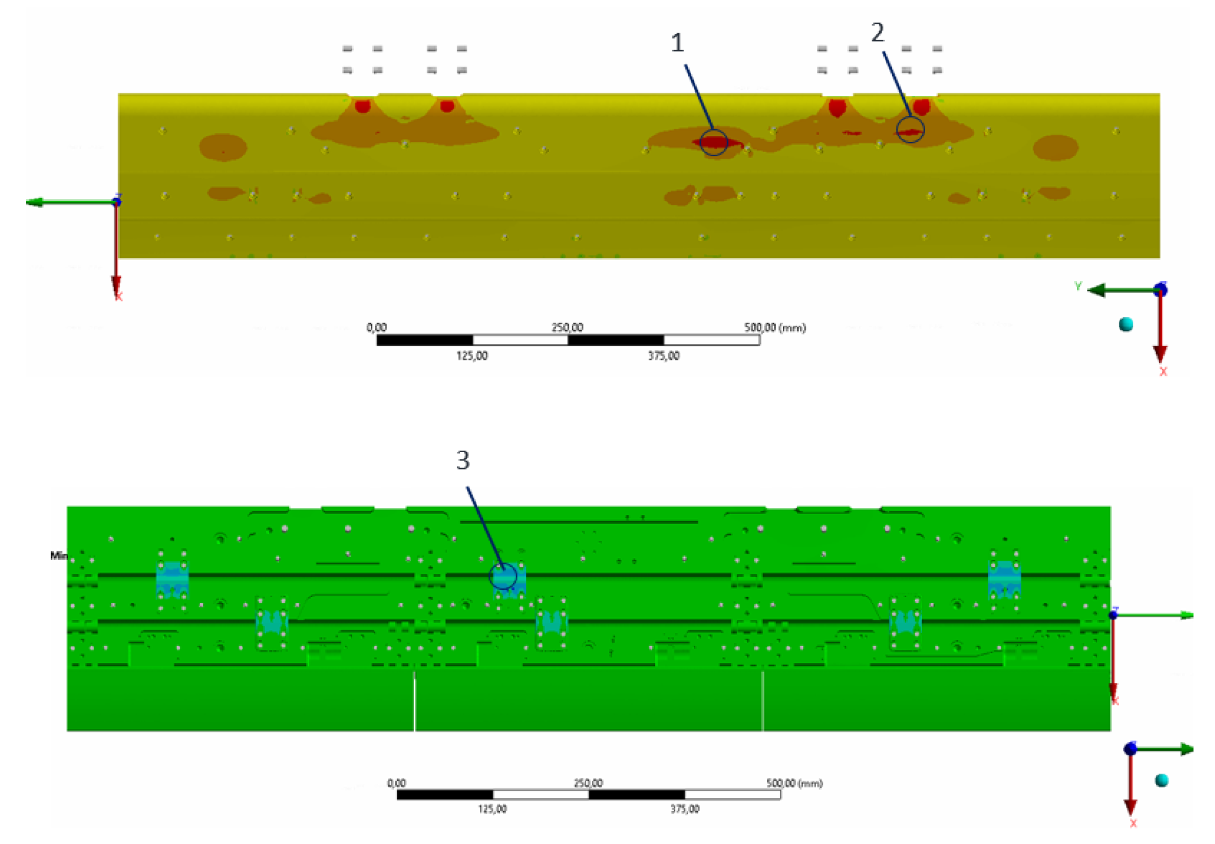
Strain gauges were placed along the areas where the maximum strain was expected on the base of numerical structural analyses. Four different areas for the outer flap and three different areas for the inner flap were identified. The regions designated for the outer and inner flaps and the associated strain distributions are shared in Figure 7 and Figure 9. Facing obstacles when attempting to precisely position strain gauges in areas of peak stress was expected due to geometric variances such as curvature or inconsistencies in thickness. In this research, efforts were made to locate the gauges as proximate to these points as feasible. Also, it was observed that not all detected areas were physically suitable for attaching strain gauges on the flap.
Therefore, three strain gauges have been attached to the outer flap and three strain gauges to the inner flap.
Figure 7.
High Strain Point for Outer Flap obtained from the implementation of CFD Loads.
Strain gauge number 1 was mounted on the first locker to the left. Meanwhile, strain gauge number 2 was positioned immediately beside the first locker on the right-hand side and strain gauge number 3 was mounted on the rear outer surface of the S1 segment. For a detailed visual representation of where these strain gauges have been placed, one can refer to Figure 8, which provides a comprehensive illustration of their locations.
Figure 8.
Strain Gauge Location for Outer Flap.
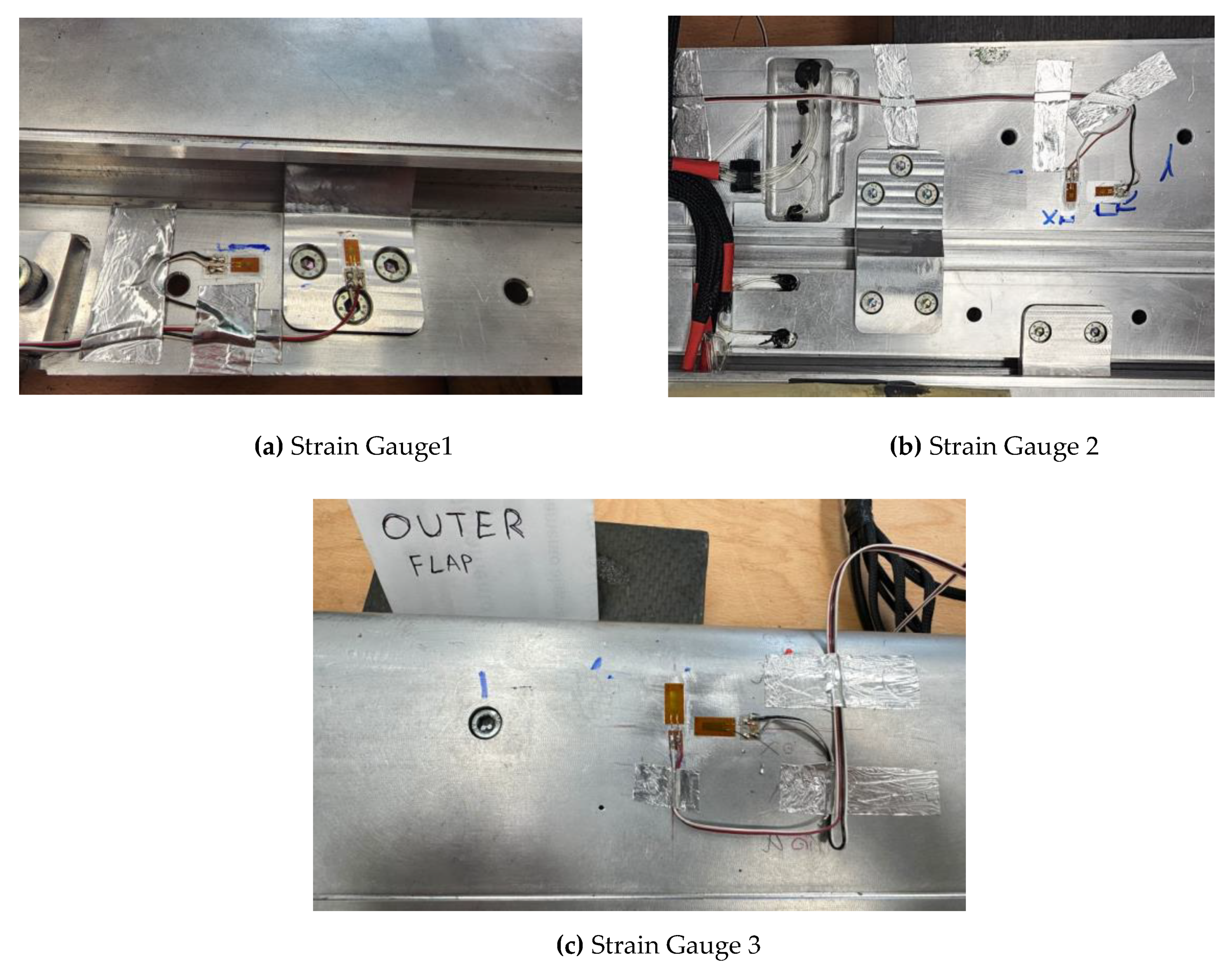
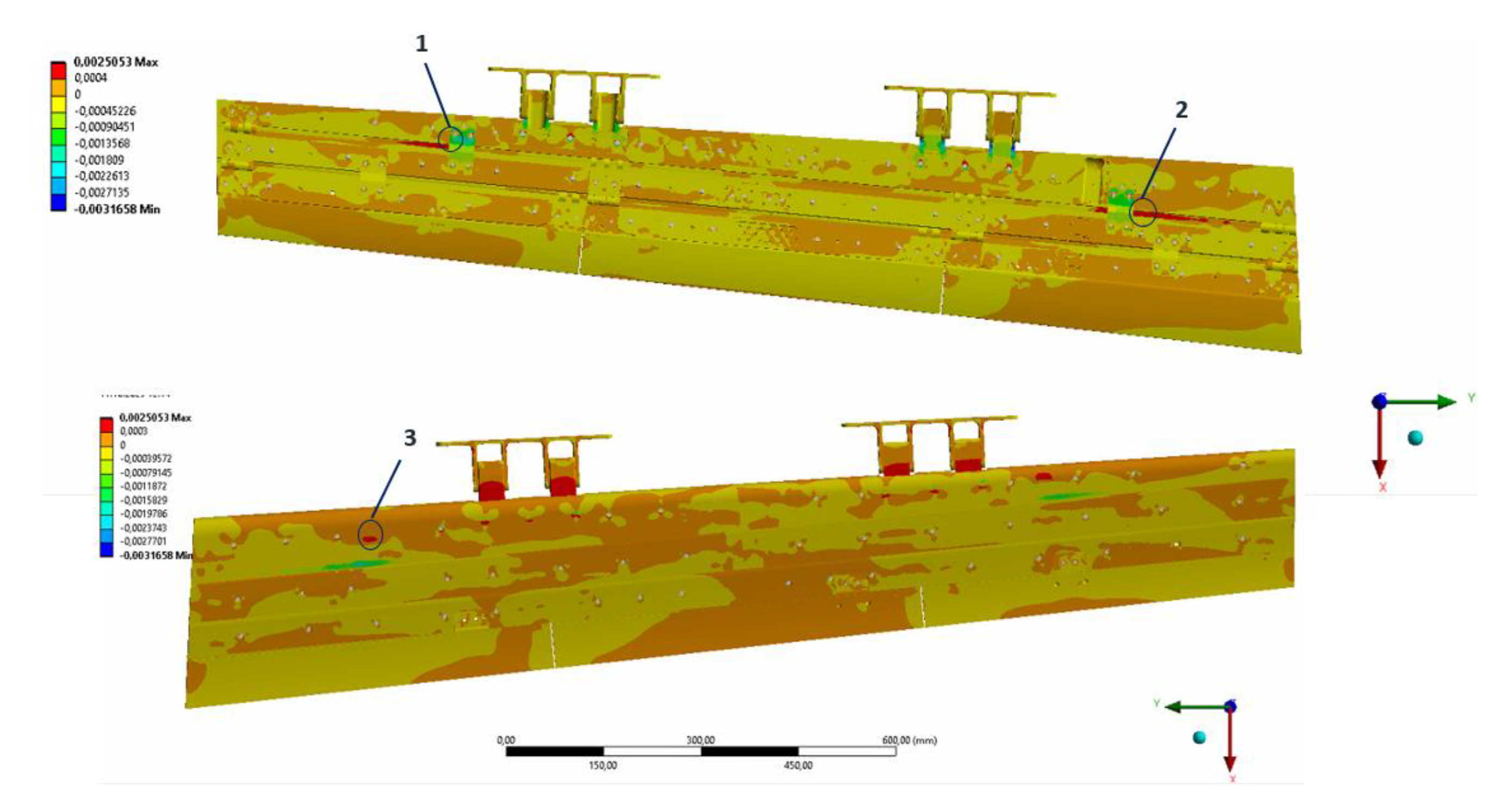
Figure 9.
High Strain Point for Inner Flap obtained from the implementation of CFD Loads.
Strain gauges were attached to the inner flap in locations as close as possible to the high strain areas indicated in Figure 9. As expected, Figure 9 shows that the areas near the flap brackets have the highest strain concentrations. Nevertheless, due to the curvature and unsuitability of these areas for strain gauge attachment, points 1, 2, and 3 were selected. Figure 10 shows the strain gauges that were adhered to the inner flap. Strain gauge 1 was positioned slightly below the flap bracket on the lower cover surface of segment 1. Strain gauge 2 was adhered to the lower cover surface of segment 2. Strain gauge 3 was mounted on the middle locker, which connects segment 1 with segment 2.
5. Static Test Set-Up: Tooling and Measure Equipment
The primary objective of conducting a static test was to validate the flap’s capability to withstand limit loads without permanent distortions, failures, or structural buckling. To ensure the accuracy and reliability of the results, meticulous numerical simulations were executed, serving several purposes:
1. Approach the experiment campaign in a logical manner with a focus on promptly identifying any potentially hazardous deviations between the actual structural behavior of the flap and its expected behavior.
2. Precise determination of the optimal location on the prototype for installing deformation and displacement sensors was carried out, guaranteeing comprehensive data collection during the test.
3. Rigorous verification of the adequacy and effectiveness of the test rig and the load transfer mechanism was conducted, ensuring their suitability for accurately simulating real-world conditions.
To achieve these objectives, a comprehensive finite element model, previously utilized during the flap design process, was merged with the finite element model of the test rig. This integration enabled the accurate reproduction of load transmission paths, commonly referred to as the “whiffle-tree”, and the constrained conditions that are expected during the tests.
Figure 11 shows the assembled model, which combines the flap and the test rig. Figure 11a–c show the isometric, side, and front views of the test rig, respectively, while Figure 11d shows the attachment method of the flap to the test rig. The loading arrangement depicted in Figure 11 utilized the whiffle tree concept. Testing was conducted using inner and outer flap blade. The whiffle tree allowed for multiple loads to be applied using a single load introduction. This loading approach offers the advantage of requiring fewer hydraulic actuators compared to conventional methods involving multiple loading or a single crank. To emulate the hydraulic jack’s action located at the top of the whiffle tree, a single consolidated force of 1500 N was applied. This force represents a scaled limit load condition.
The 150kg traction load was divided into 3 loads of 50kg through the load distribution frame. It is shown with a purple arrow in Figure 13.
For the application of load via the frame onto the flap, it was essential to bond the frame onto the upper side of the flap from these specific surfaces illustrated in Figure 13. To assure the adhesion remains effective throughout the testing process, it was necessary to perform an adhesive strength test.
Three different adhesives listed in Table 2 were tested. The surfaces applied with adhesives 1 and 3 successfully sustained loads up to an approximate 100 kilograms respectively and thus met the testing criteria. However, the surface to which adhesive 2 was applied failed when it detached at a load of 45 kilograms. Despite adhesive 1’s rapid curing time and ease of application, it was difficult to remove from surfaces without leaving residue after curing, leading to the decision to use adhesive number 3 during structural testing. Figure 12 shows the adhesive test setup.
Figure 12.
Adhesive test setup.
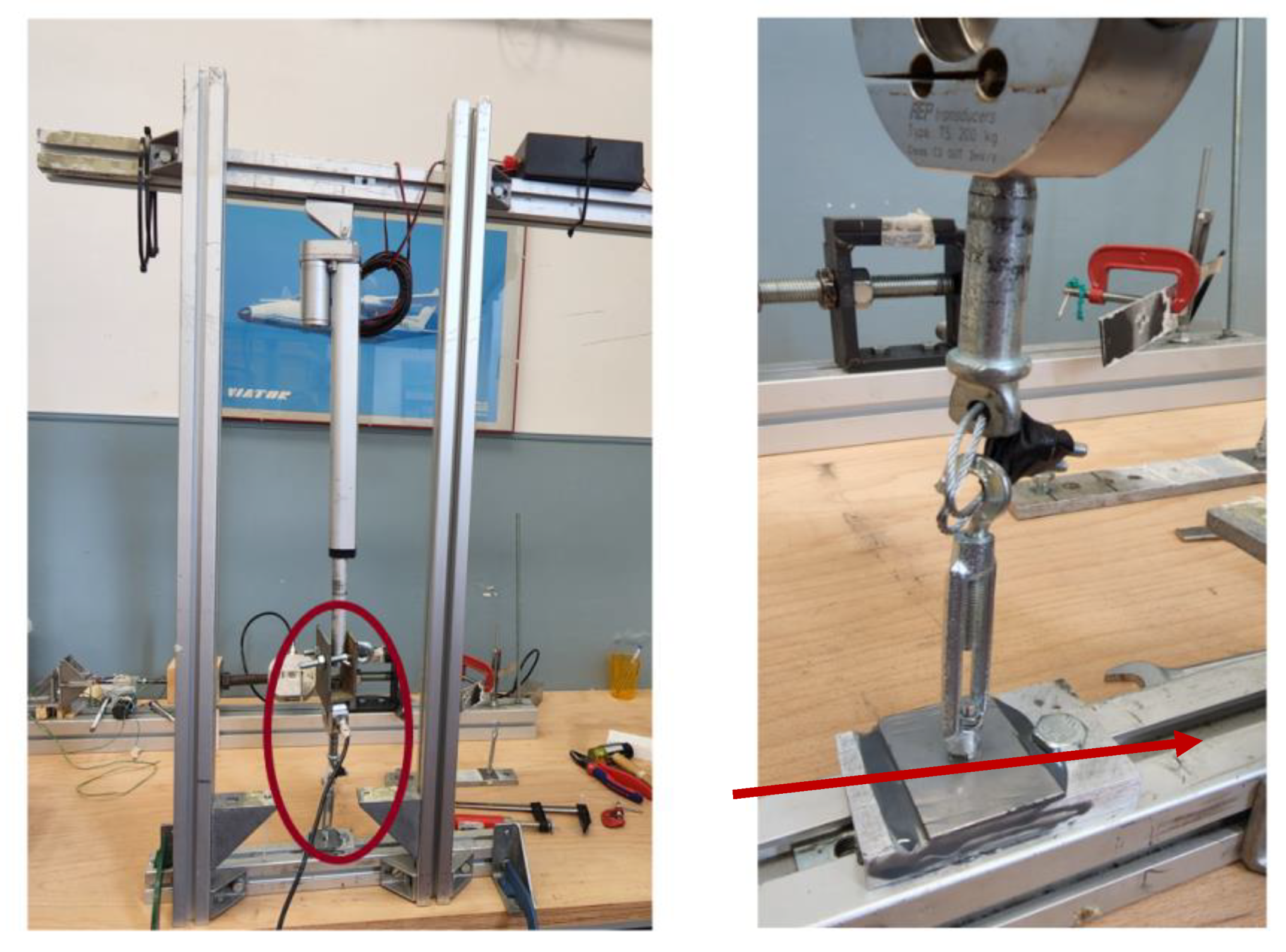
On the basis of pre-test analyses, strain gauges were positioned in the most stressed zones of the rib links and spar, being the max expected strain sensor (MSS) located on the second rib linking beam element (L1).
Load data have been measured by the use of a load cell; displacements have been measured by the use 2 linear transducers and 1 rotative transducer (potentiometers); deformations have been measured by the use 3 couples of strain gauges positioned on the base of numerical stress analysis. Figure 13 show the overall test set-up, with identification of different components.
Figure 13.
Static Setup details and load frame distribution.

Instruments specifications are reporter in the Table 3.
6. Test Procedure
Step 1: The inner flap has been installed onto the support apparatus.The flap, as depicted in Figure 14, is rigidly attached to the support frame.
Step 2: Two linear displacement transducers were located at each end of the flap, and a rotative displacement transducer were placed centrally. (Figure 15)
7. Results and Discussion
The morphing flap technology has undergone a gradual and sustained maturation process, culminating in the development of a scaled prototype for final wind tunnel testing under realistic operational conditions. Building upon existing mature technological solutions that demonstrate functionality and robustness, new research avenues are being explored to further improve the morphing flap in relation to the diverse requirements associated with cost-effective and sustainable integration at the aircraft level. Consequently, a systematic re-engineering of the flap’s constituent elements is anticipated to facilitate the transition from a reliable integrated smart system to an economically viable and competitive aeronautical component. This section provides a comprehensive analysis and interpretation of the findings presented in the article. The experimental data is utilized to validate the corresponding finite element models, which are employed to predict structural behavior under diverse loading conditions. This data provides valuable insights into the interaction among the various integrated functionalities and the structural responses.
Figure 16 depicts the temporal evolution of the applied force exerted on outer and inner flap during the testing phase. The methodology for the load application involves meticulous increments in adjustments to ensure a steady progression towards the desired static load level across the flaps. Once the criterion for the static load is satisfied, the procedure transitions to an unloading phase, which systematically reduces the applied force to assess the structural response during load reversal.
Figure 17 displays the displacement’s evolution as a function of time. The findings highlight two key points. Firstly, the outer flap mechanism reaches a displacement apex of 15.78 mm under the maximal load conditions. Under the same load conditions, the maximum displacement of the outer flap mechanism is 6.77 mm.Secondly, the change in displacement demonstrates remarkable consistency across the range of loads applied. The measurement error, associated with the applied load, was determined by calculating the standard deviation of the measured displacements at the selected locations during the experiment.
Figure 18 shows the time-dependent variation of strain as measured by the strain gauges depicted in Figure 8 and Figure 9.
The strain measurements are captured using data acquisition software. It is unfortunate that the sensor designated for the measurement of e3x experienced a failure, and notably, a parallel malfunction was observed in the sensor for the outer flap. Nonetheless, this particular problem is not critical for the FE model’s validation process. It has been observed that the strain values change in correlation with the applied load and the observed displacement.
The measured displacement and strain values for the inner flap, as well as those obtained from finite element analysis, are compared in Table 4. d1 represents the dataset obtained from the linear displacement transducer positioned at the right trailing edge of the flap, illustrated in Figure 13. d2 corresponds to the measurements acquired by the linear displacement transducer placed at the left trailing edge of the flap. Furthermore, d3 comprises the data procured from the rotary displacement transducer affixed precisely at the midpoint of the flap’s trailing edge. The maximum displacements measured as d1, d2, and d3 are respectively recorded as 6.47, 6.39, and 6.77, and the error rates of the FE model analysis results have been determined to be 3.55%, 3.28%, and 7.68% correspondingly.
The strain gauge meant to measure the e3x value was damaged during the experiment; therefore, its value is not presented. For the rest of the strain gauges, it can be seen that at the maximum applied load, the maximum magnitudes of the normal strain in the x and y directions reach approximately 85 and 62 microstrain, respectively. Both peaks occur at the location marked in Figure 10c, which is situated in the second locker, hosting the most load-bearing parts. Observing the maximum strain in this region is a predictable consequence resulting from the additional stress on the lockers, which is caused by the load transitions between blocks, as well as the moments created on the locker by the test loads.
Based on the obtained results, evaluation of the measurement inaccuracies for normal strains was performed. On average, these errors in normal strain measurements were established to be 2.5 microstrains ± 5 micro-strains.
The images in Figure 19, which are referred to as references in Table 4, exhibit the distributions of displacement and strain in specified strain gauge regions obtained from the FE analysis.
The comparisons of displacement and strain for the outer flap from both measurements and finite element analysis are shown in Table 5. The maximum displacements, labeled as d1, d2, and d3, were found to be 9.62, 15.78, and 14.14, respectively. The errors in the finite element model analysis for these measurements were calculated to be 13.4%, 9.06%, and 0.77%, correspondingly. The strain gauge meant to measure the e3x strain was damaged during testing, hence that data is not available. However, the data from the other strain gauges show that the maximum normal strains, under the full load, were about 203 microstrain in the x direction and 159 microstrain in the y direction. These highest strain values were found at the location indicated in Figure 8c, on the back of the flap, where increased strain is expected due to the stress on the inner locker caused by the load’s reaction force. An evaluation of the normal strain measurement errors yielded an average error of 3.5 microstrain, with a standard deviation of ± 6.5 micro-strains.
8. Conclusions
This article presents the evaluation of the design, structural analysis, and structural testing of the morphing flap concept. The experimental work enhances the understanding of the structural integrity of the tested morphing flap prototype, while also validating the design methodology used to fabricate the prototype.
The test article’s structural layout was derived using numerical stress analysis, which required examining extreme combinations of flap configurations and test loads. The test article has been confirmed to meet the safety standards for wind tunnel operations, with a safety margin of 3 to account for local plasticization during extreme load circumstances. In order to validate these findings, a stationary test was carried out prior to the installation in the wind tunnel. Due to limited resources and time, the testing procedure was streamlined to prevent an exact duplication of the most intense load distribution. Three reference stations were randomly chosen along the span of the flap. The greatest pressure distribution of 150 kg was applied using a basic wiffle tree. The simplified load distribution was replicated numerically to validate the finite element model and verify its reliability under simulated pressure distributions in the wind tunnel. The model’s validation was determined by comparing the anticipated displacements and strains to the experimental outcomes, with a tolerance of ±10% for displacements and ±5% for strains.
The only divergence from the targets was noticed for displacements d1. However, the model was still declared “validated” because the discovered variation was attributed to the elasticity of the test-article constraint, which was not replicated in the FE model where all constraints are perfectly stiff. Hence, the displacement at the edge of the flap during the test exceeded the expected result by a little margin.
The main reason for observing this difference is the flexibility of the test substance restriction, and despite this difference, the fact that the results are beyond the limits reinforces the validity of the FE model. Considering the elasticity of test-article and difference between experimental and FEM results, the notable consistency between values from measurements and those from computational results validates the approach employed in constructing the finite element (FE) model.
This led to the conclusion that the modeling methodologies used throughout the testing and design stages were entirely reliable. Consequently, the results inferred from calculations under ultimate load levels relevant to the wind tunnel test campaign supported the suitability of the scaled flap prototype for testing.
Author Contributions
M.S.S.D.- Generation of the structural analysis, design of morphing flap model, assessment of results. Draft and final paper preparation; R.P.- Supervision of the activities, Support to paper preparation, revision and editing, Coordinating the production process; L.C. – Conducting structural test and data collection; M.V. - Conducting structural test and data collection; M.O.K. – Supervision.
Funding
Part of the research described in this paper has been carried out in the framework of AIRGREEN2 Project, which gratefully received funding from the Clean Sky 2 Joint Undertaking, under the European’s Union Horizon 2020 research and innovation Program, Grant Agreement No. 807089—REG GAM 482 2018—H2020-IBA-CS2-GAMS-2017. Part of the work here presented was funded by TUBITAK 2214-A - International Research Fellowship Programme for Ph.D. Students.
Data Availability Statement
Data is contained within the article.
Conflicts of Interest
The authors declare no conflict of interest.
References
- Anderson, J.D. Jr (2011), Fundamentals of aerodynamics. McGraw-Hill Higher Education, 3rd edition.
- Chopra I (2002) Review of state of art of smart structures and integrated systems. AIAA Journal 40: 2145–2187. [CrossRef]
- Lachenal X, Daynes S and Weaver P (2013) Review of morphing concepts and materials for wind turbine blade applications. Wind Energy 16: 283–307. [CrossRef]
- Dobrzynski W (2010) Alomost 40 years of airframe noise research: what did we achieve Journal of Aircraft 47(20): 353–367. [CrossRef]
- Holle, A.A. Plane and the like for Aeroplanes. U.S. Patent N.1225711, 8 May 1917.
- Parker, H.F. The Parker Variable Camber Wing; NACA Technical Report 77; Government Printing Office: Washington, DC, USA, 1920.
- Hardy, R. AFTI/F-111 mission adaptive wing technology demonstration program. In Proceedings of the 1983 AIAA Aircraft Prototype and Technology Demonstrator Symposium, Air Force Museum, Dayton, OH, USA, 23–24 March 1983.
- Bonnema, K.L. AFTI/F-111 Mission Adaptive Wing Briefing to Industry. Air Force Wright Aeronautical Laboratories, Air Force Systems Command, Wright-Patterson Air Force Base; AFWAL Technical Report TR-88-3082, ADA202467; Defense Technical Information Center: Fort Belvoir, VA, USA, 1988.
- Meyran, P.; Pain, H.; Botez, R.M.; Laliberté, J. Morphing winglet design for aerodynamic performance optimization of the CRJ-700 Aircraft, Part 1—Structural Design. INCAS Bull. 2021, 13, 113–128. [CrossRef]
- Meyran, P.; Pain, H.; Botez, R.M.; Laliberté, J. Morphing winglet design for aerodynamic performance optimization of the CRJ-700 Aircraft, Part 2—Control. INCAS Bull. 2021, 13, 129–137.
- Segui, M.; Abel, F.R.; Botez, R.M.; Ceruti, A. New aerodynamic studies of an adaptive winglet application on the Regional Jet CRJ700. Biomimetics 2021, 6, 54.
- Segui, M.; Mantilla, M.; Botez, R.M. Design and validation of an aerodynamic model of the cessna citation x horizontal stabilizer using both OpenVSP and digital Datcom. Int. J. Mech. Ind. 2018, 12, 45–53.
- Segui, M.; Bezin, S.; Botez, R.M. Cessna citation x performance improvement by an adaptive winglet during the cruise flight. Int. J. Mech. Ind. 2018, 12, 423–430.
- Campanile LF and Sachau D (2000) The belt-rib concept: a structronic approach to variable camber. Journal of Intelligent Material Systems and Structures 11(3): 215–224.
- Campanile LF and Anders S (2004) Aerodynamic and aeroelastic amplification in adaptive belt-rib airfoils. Aerospace Science and Technology 9: 55–63.
- Bartley-Cho JD, Wang DP, Martin CA, et al. (2004) Development of high-rate, adaptive trailing edge control surface to the smart wing phase 2 wind tunnel model. Journal of Intelligent Material Systems and Structures 15: 279–291.
- Daynes S and Weaver P (2012a) A morphing trailing edge device for a wind turbine. Journal of Intelligent Material Systems and Structures 230: 691–701.
- Daynes S and Weaver P (2012b) Design and testing of a deformable wind turbine blade control surface. Smart Materials and Structures 21: 105019–105029.
- www.cleansky.eu.
- Hetrick, J. A., Osborn, R. F., Kota, S., Flick, P. M., & Paul, D. B. (2007). Flight Testing of Mission Adaptive Compliant Wing. 48th AIAA/ASME/ASCE/AHS/ASC Structures, Structural Dynamics, and Materials Conference. Honolulu, Hawaii, USA. [CrossRef]
- You, Hangil & Kim, Seongik & Yun, Gunjin. (2019). Design Criteria for Variable Camber Compliant Wing Aircraft Morphing Wing Skin. AIAA Journal. 58. 1-12. 10.2514/1.J058002.
- FlexSys, Inc. (n.d.). Flexibly Engineering the “Impossible”, FlexFoil™ Compliant Control Surfaces. Retrieved from FlexSys: https://www.flxsys.com/flexfoil.
- Baccus, J. (2017, May 26). NASA Flight Tests Advance Research of Flexible, Twistable Wing Flaps for Improved Aerodynamic Efficiency. Retrieved from NASA: https://www.nasa.gov/feature/nasa-flight-tests-advance-research-of-flexibletwistable-wing-flaps-for-improved-aerodynamic.
- Pecora R, Amoroso F, Amendola F, et al. Validation of a smart structural concept for wing-flap camber morphing. Smart Structures and Systems 2014; 14(4), 659–678.
- Pecora R, Barbarino S, Concilio A, et al. Design and functional test of a morphing high-lift device for a regional aircraft. Journal of Intelligent Material Systems and Structures 2011; 22(10), pages 1005–1023.
- Moens, F. Augmented aircraft performance with the use of morphing technology for a turboprop regional aircraft wing. Biomimetics 2019; 4(3), 1–20.
- Pecora R, Amoroso F, Magnifico M, et al. (2016a) KRISTINA: kinematic rib-based structural system for innovative adaptive trailing edge. In: Proceedings of the SPIE industrial and commercial applications of smart structures technologies 2016, 980108, Las Vegas, NV, 20 March, vol. 9801.
- Pecora R, Concilio A, Dimino I, et al. (2016b) Structural design of an adaptive wing trailing edge for enhanced cruise performance. In: 24th AIAA/AHS adaptive structures conference, San Diego, CA, 4–8 January. Reston.
- Arena, M., Amoroso, F., Pecora R., Ameduri, S., “Electro-actuation system strategy for a morphing flap”, Aerospace, Vol. 6(1), Art. 1, 2019.
- Pecora R, Amoroso F, Sicim M.S. Design of a morphing test-article for large-scale, high-speed wind tunnel tests of an adaptive wing flap. SPIE 2021 Conference on Active and Passive Smart Structures and Integrated Systems XV, March 22-26, 2021.
- https://www.easa.europa.eu/en/newsroom-and-events/press-releases/easa-clean-aviation-enhance-cooperation-research-and-innovation.
- Sicim, M.S., Pecora R., Kaya M.O., Design of a large-scale model for wind tunnel test of a multiadaptive flap concept. Chinese Journal of Aeronautics, 2024, vol. 37, pages 58-80.
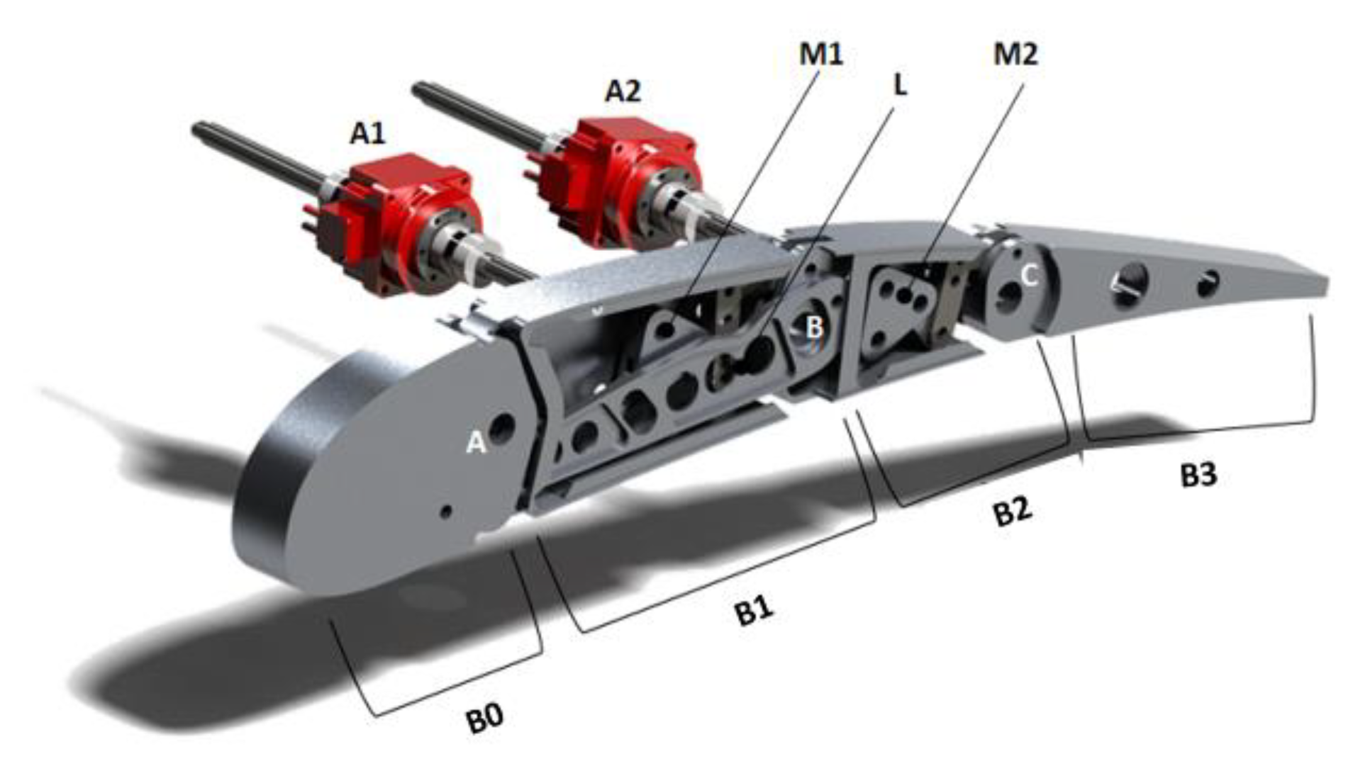
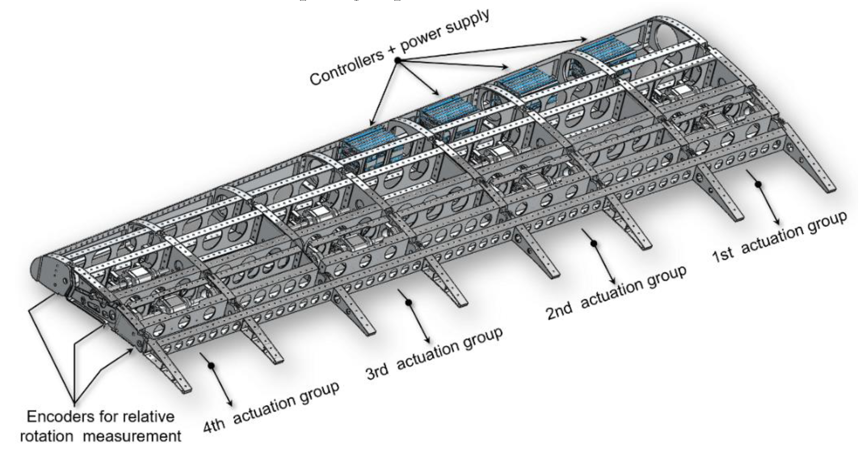
Figure 5.
Mechanical layout of the flap.
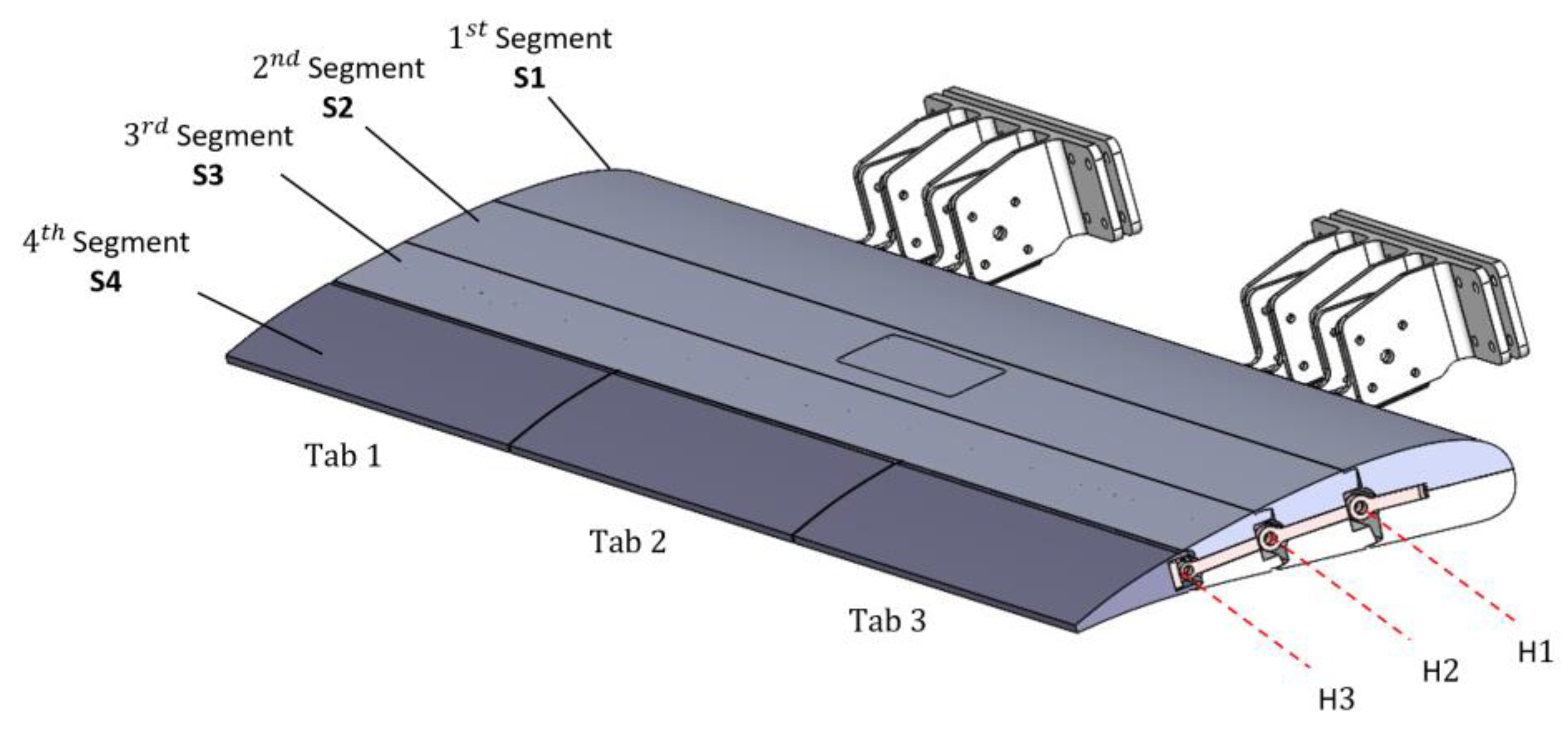
Figure 6.
Material list for each part of the flap.
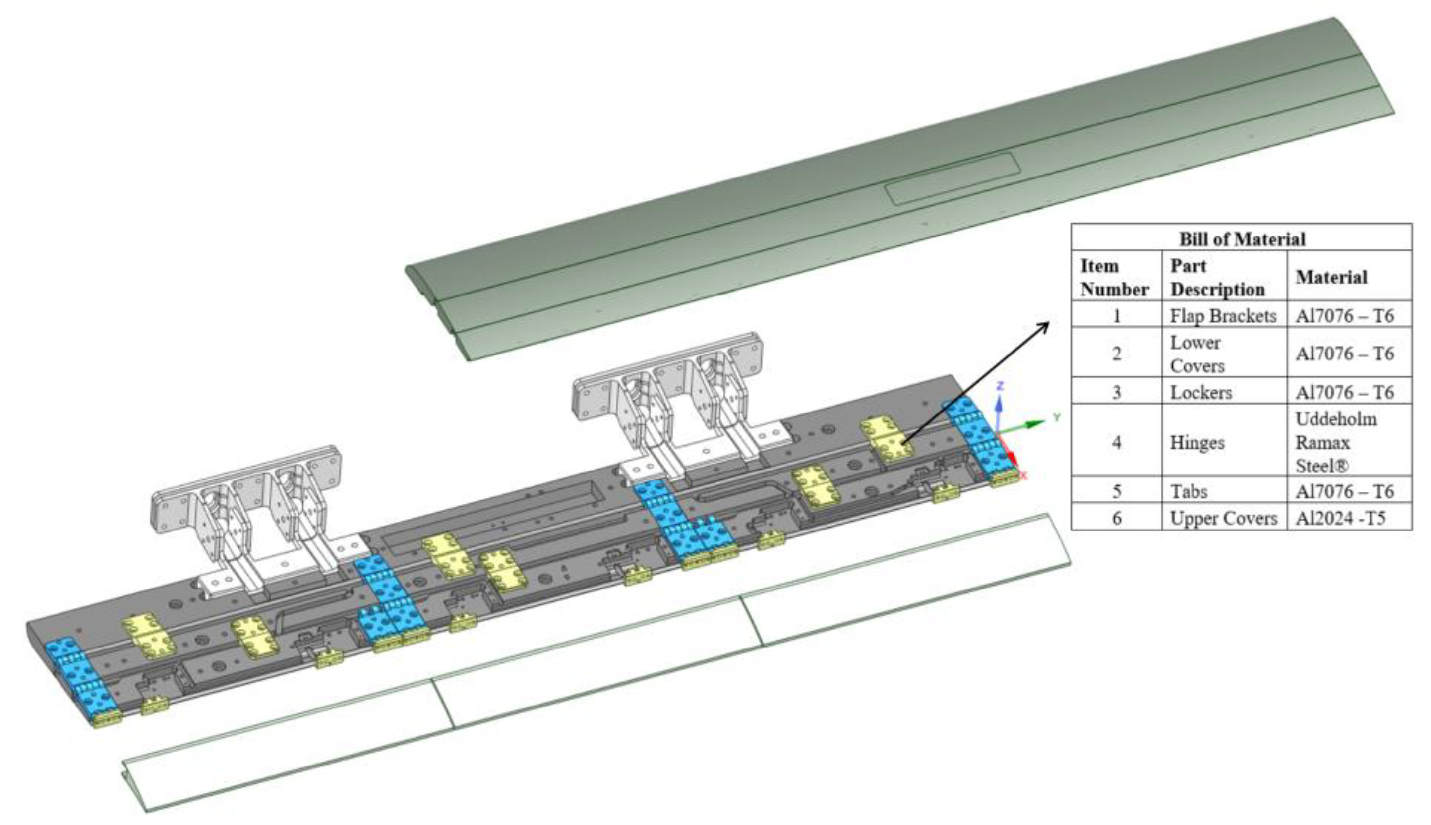
Figure 10.
Strain Gauge Location for Inner Flap.
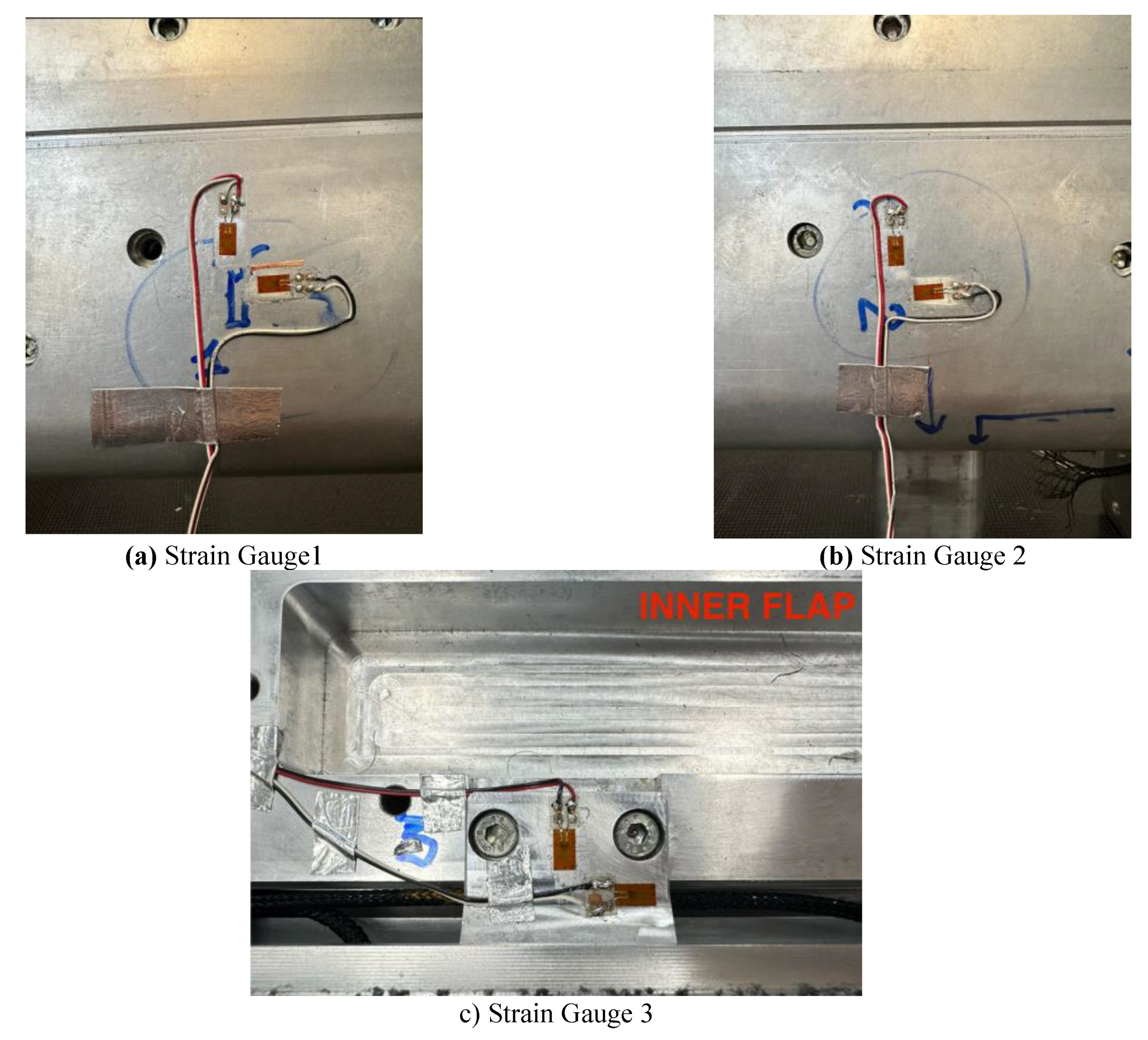
Figure 11.
Morphine flap: static test set -up.
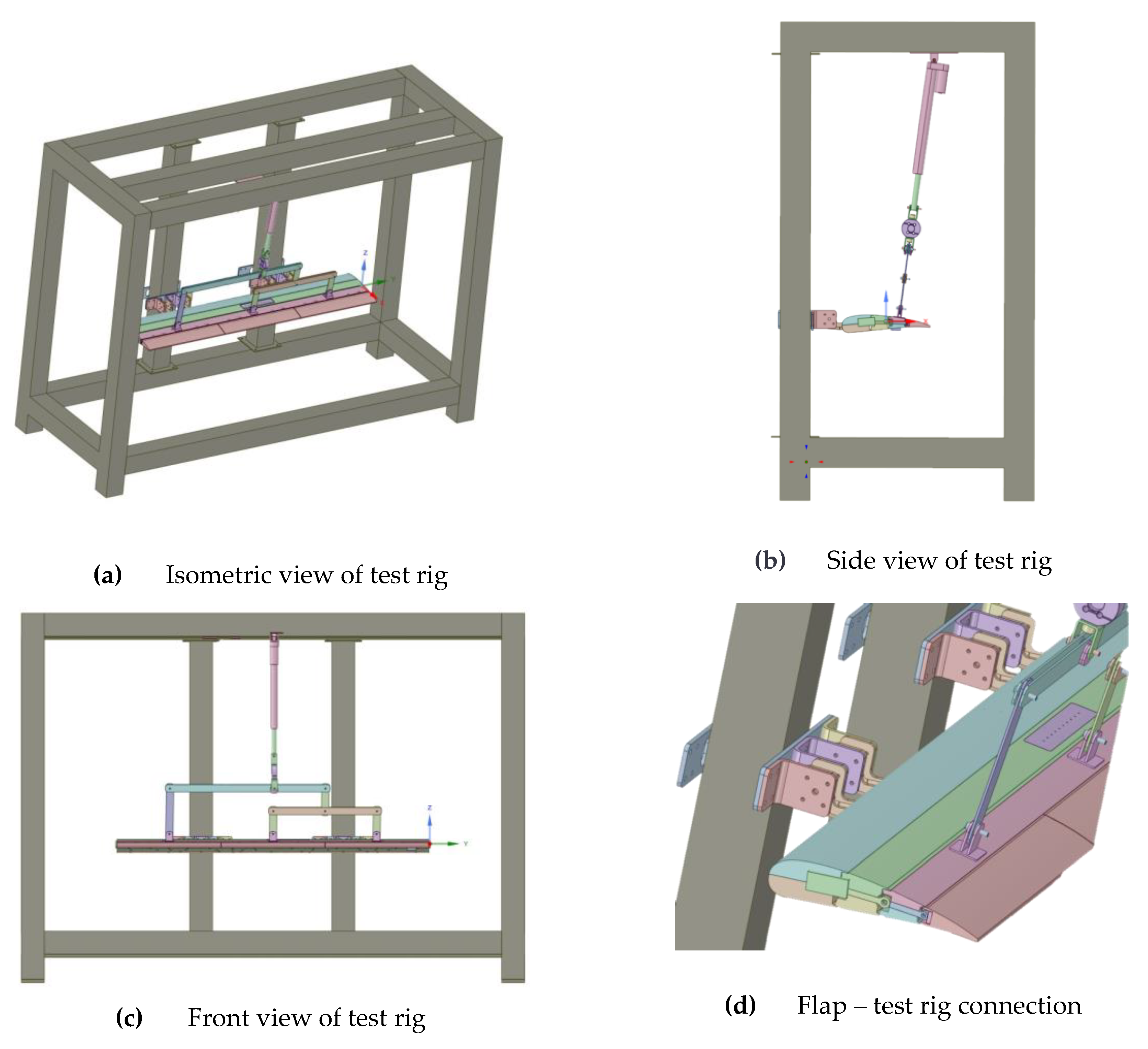
Figure 14.
Connection points of the flap to the test set up.
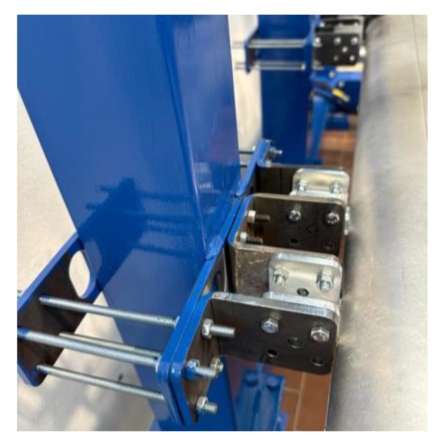
Figure 15.
Linear and rotative displacement transducers position used in static test.
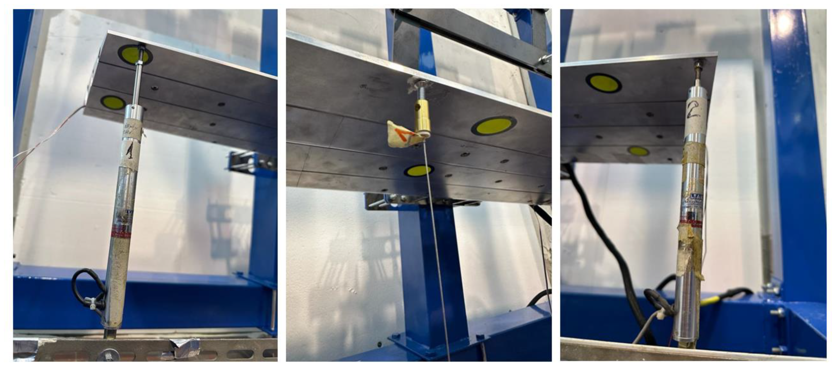
Figure 16.
Applied force vs time during static test.

Figure 17.
Linear Applied force over time during static tests.
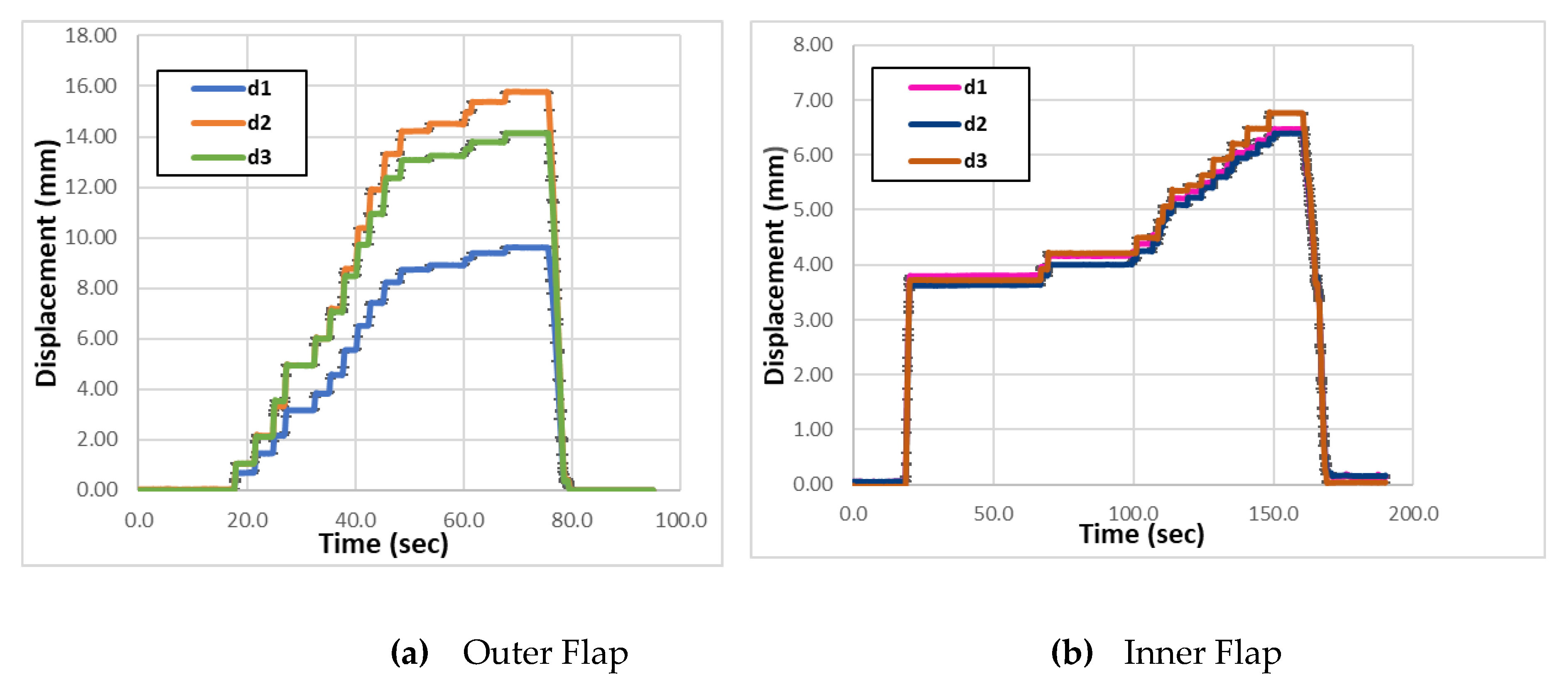
Figure 18.
Strain vs time data obtained during the static test .
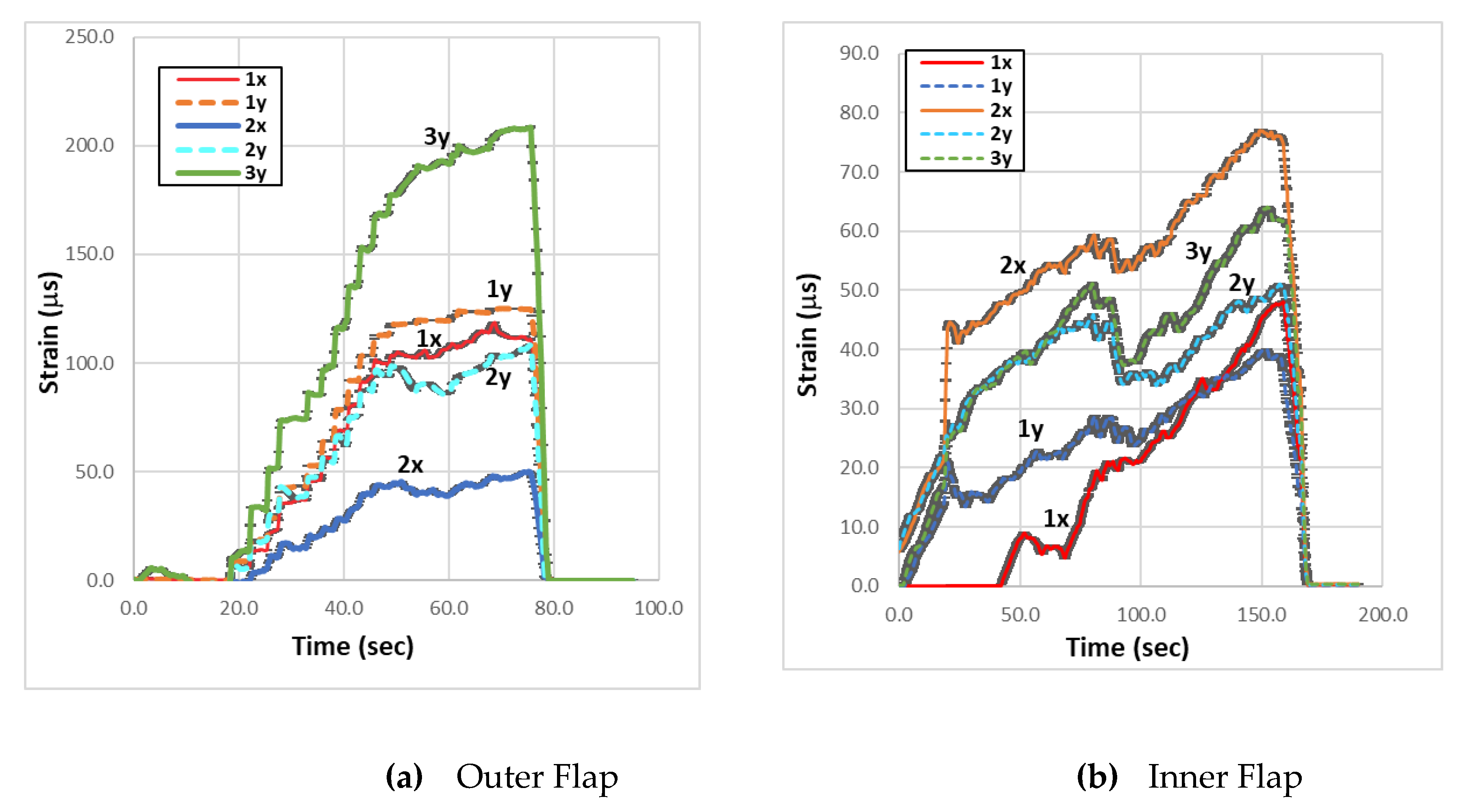
Figure 19.
Analysis results visuals of the analysis results given in Table 4 (Inner Flap).
Figure 19.
Analysis results visuals of the analysis results given in Table 4 (Inner Flap).

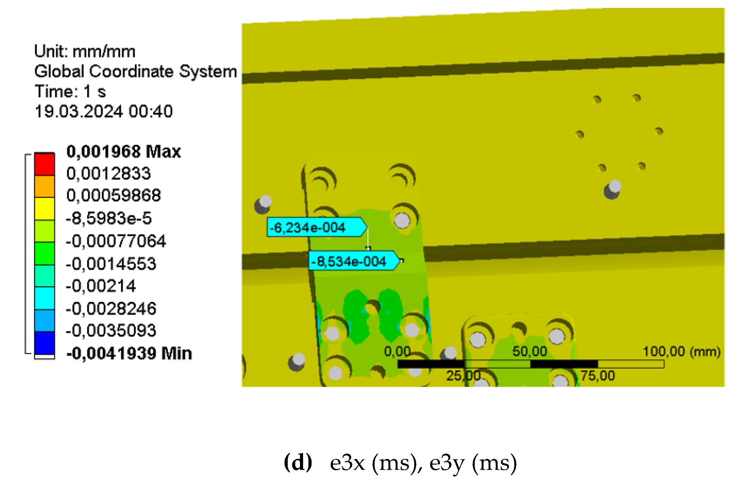
Figure 20.
Analysis Results Visuals of the analysis results given in Table 5 (Outer Flap).
Figure 20.
Analysis Results Visuals of the analysis results given in Table 5 (Outer Flap).
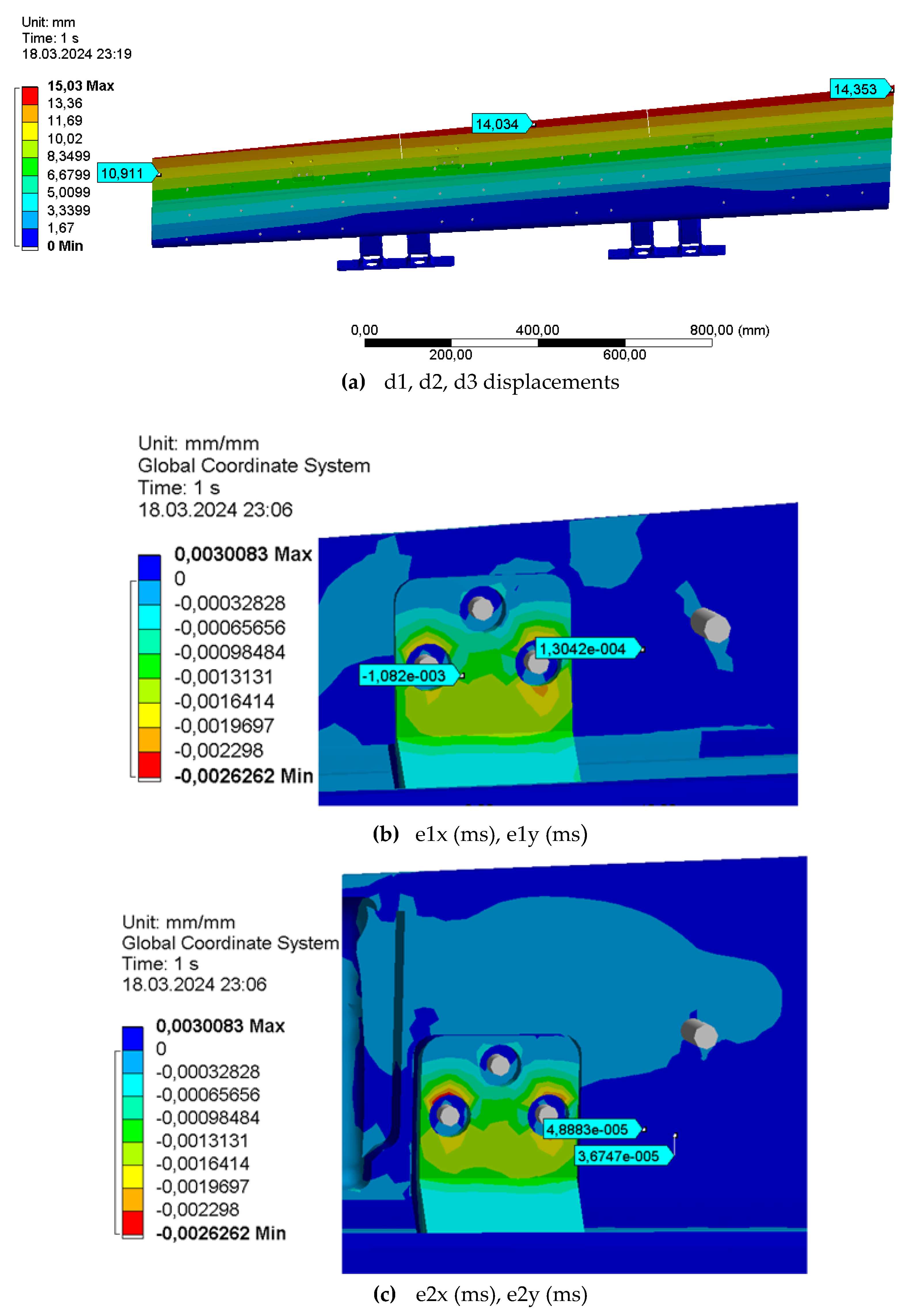
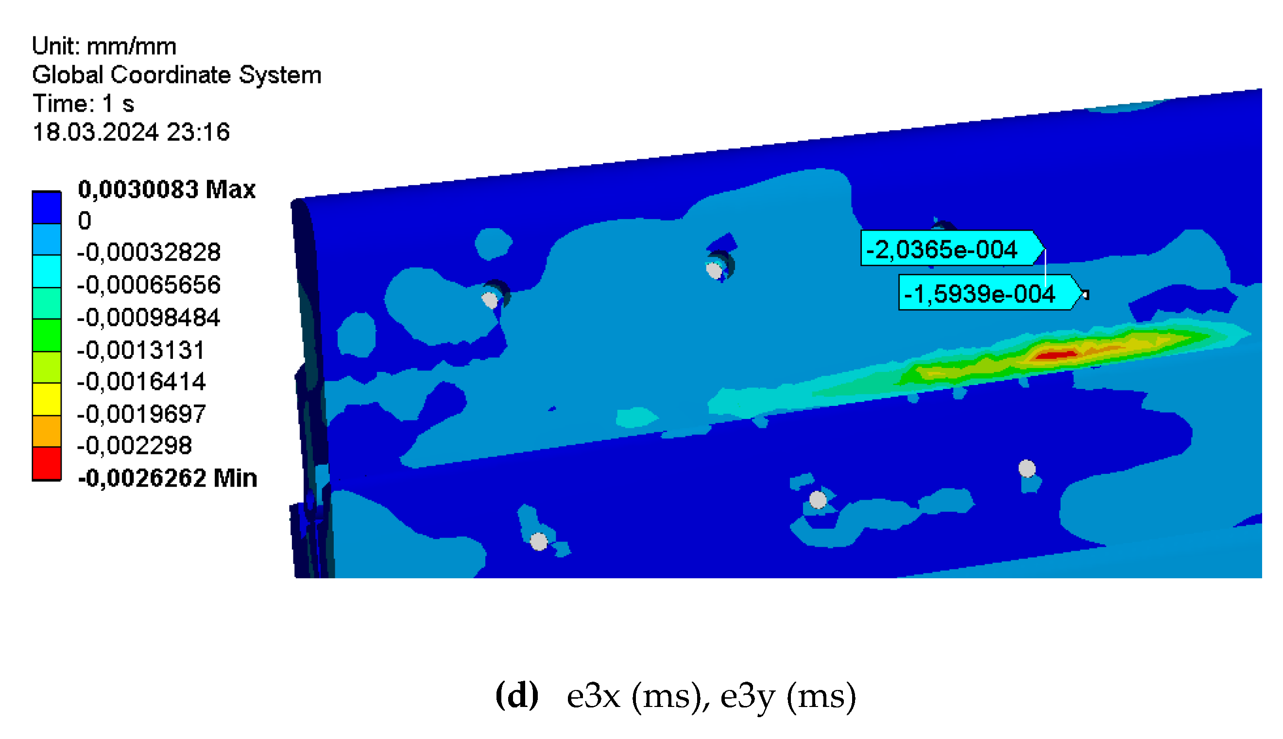

Table 1.
Detailed dimensions of scale wind tunnel model.
| Item | Dimension (mm) |
|---|---|
| Wing span | 4466.23 |
| Inboard Flap span | 1359.73 |
| Outer Flap span | 1703.04 |
| Inner flap root chord | 292.77 |
| Inner Flap tip chord | 292.77 |
| Outer Flap root chord | 293.9 |
| Outer Flap tip chord | 213.05 |
Table 2.
Adhesive List.
| Number | Item | Test Results | Max Applied Load (kg) |
|---|---|---|---|
| 1 | X60 Cold Curing Glue | Pass | 100 |
| 2 | Pattex Millechiodi Forte & Rapido | Fail | 45 |
| 3 | 3M Scotch-Weld Epoxy Adhesive 2216 | Pass | 100 |
Table 3.
List of instruments.
| Item | Model | Measurement error (%) |
|---|---|---|
| Lms Scadas | Daq Mobile | - |
| Load Cell | TS – 200kg Class C2 | 0.03 |
| Linear Actuator | L11TGF12V50-T-1 | - |
| Rotative Displacement Transducer | Enosis Sensor | 0.02 |
| Linear Displacement Transducer | Gefran PA-12-A-50 | 0.01 |
| Strain gauge | Mono axial1-LY13-3/120 | - |
Table 4.
Test and Analysis Results for Inner Flap.
| Location. | Test Results | Analysis Results | Ref. Figure | Error Rate % |
|---|---|---|---|---|
| d1 (mm) | 6.47 | 6.24 | 24 (a) | 3.55 |
| d2 (mm) | 6.39 | 6.18 | 24 (a) | 3.28 |
| d3 (mm) | 6.77 | 6.25 | 24 (a) | 7.68 |
| e1x (ms) | 47.81 | 42.77 | 24 (b) | 10.54 |
| e1y (ms) | 37.96 | 37.96 | 24 (b) | 0.02 |
| e2x (ms) | 75.41 | 77.89 | 24 (c) | -3.38 |
| e2y (ms) | 50.67 | 49.57 | 24 (c) | 2.18 |
| e3x (ms) | - | 85.34 | - | - |
| e3y (ms) | 61.69 | 62.35 | 24 (d) | -1.06 |
Table 5.
Test and Analysis Results for Outer Flap.
| Location | Test Results | Analysis Results | Ref. Figure | Error Rate % |
|---|---|---|---|---|
| d1 (mm) | 9.62 | 10.91 | 25 (a) | -13.4 |
| d2 (mm) | 15.78 | 14.35 | 25 (a) | 9.06 |
| d3 (mm) | 14.14 | 14.03 | 25 (a) | 0.77 |
| e1x (ms) | 112.02 | 108.2 | 25 (b) | 3.41 |
| e1y (ms) | 124.827 | 130.4 | 25 (b) | -4.46 |
| e2x (ms) | 38.15 | 36.74 | 25 (c) | 3.69 |
| e2y (ms) | 49.833 | 48.88 | 25 (c) | 1.91 |
| e3x (ms) | - | 159.39 | - | - |
| e3y (ms) | 207.594 | 203.65 | 25 (d) | 1.89 |
Disclaimer/Publisher’s Note: The statements, opinions and data contained in all publications are solely those of the individual author(s) and contributor(s) and not of MDPI and/or the editor(s). MDPI and/or the editor(s) disclaim responsibility for any injury to people or property resulting from any ideas, methods, instructions or products referred to in the content. |
© 2024 by the authors. Licensee MDPI, Basel, Switzerland. This article is an open access article distributed under the terms and conditions of the Creative Commons Attribution (CC BY) license (http://creativecommons.org/licenses/by/4.0/).
Copyright: This open access article is published under a Creative Commons CC BY 4.0 license, which permit the free download, distribution, and reuse, provided that the author and preprint are cited in any reuse.


