
Submitted:
23 July 2024
Posted:
24 July 2024
You are already at the latest version
Abstract
The effect of spanwise wing non-planarity, implemented in conjunction with a Gurney flap is presented. Testing was undertaken in a low speed wind tunnel using a rectangular wing with an aspect ratio of 3. The outer 1/3 of the wing was non-planar which took the form of dihedral or a circular arc. A 2% high Gurney flap was implemented such that it could extend over the entire span, or the planar inboard section. Loads were measured using a sting balance. The data shows that non-planarity increases the maximum lift coefficient and the wing’s lift curve slope. Gurney flap lift modulation was enhanced in the presence of non-planarity. The addition of Gurney flaps caused a greater minimum drag coefficient increment for the non-planar wings. The Gurney flaps reduced the lift dependent drag of the wings; however, the minimum drag coefficient was observed to increase. The Gurney flaps reduced the maximum lift to drag ratio (L/D) for the non-planar wings; however, the flat wing showed a small L/D increment with flap addition.
Keywords:
Gurney flap
; non-planar wings
; low Reynolds number
; wind tunnel testing
; spanwise camber
1. Introduction
The quest to improve wing efficiency has been an ongoing endeavor since Munk [1] initially investigated and established the requirements to minimize vortex drag for planar unswept wings. For a constrained wing span, aerodynamic efficiency may be improved through non-planarity; whose most common embodiment is the winglet [2]. Visually similar devices to the winglet include the tip sail [3,4] and the split tip [5]. These devices serve to alter the special distribution of trailing vorticity. A winglet induces an upwash over the wing, while itself experiencing no net normal-wash if optimal [2,6]. In some instances (swept wings) the winglet may also produce a forward thrust component although this is not typically associated with optimal operation. Tip sails are visually consistent with the extended primary feathers of birds of prey (raptors), and function by thrust production on the forward inclined elements of the sail [3,4]. Neither winglets or tip sails scale particularly well to the dimensions consistent with small unmanned aerial vehicles. The resulting small chord of the tip sails or winglet yields very low Reynolds number flows, such that laminar separation without re-attachment may occur, greatly reducing the efficiency of the device.
An alternative approach to improving efficiency is to camber the wing in the spanwise direction. Cone [7] and Lowson [8] showed that spanwise cambering is effective in reducing vortex drag. The non-planar wing captures a larger volume of air to generate the lift impulse; consequently the downwash at a point is lowered. As a result, the kinetic energy per unit length of the wake is reduced. Lowson [8] showed that non-planarity is most effective near the wing tips, such that for a given non-planar height an end plate may be most effective. Viscous effects must be considered when implementing non-planarity; a poor end plate wing junction may cause significant extents of flow separation. When viewed in the context of small UAV type vehicles, benefits of spanwise camber must be weighed against penalties resulting from installation and poor performance at low Reynolds number. As shown by Jansen and Perez [9] the optimal embodiment of non-planarity may depend on the function of the aircraft, i.e., long range aircraft may benefit from a “C” wing [5], while medium range aircraft benefit more from wingtip modifications.
Lift augmentation using Gurney flaps (GFs) has received considerable attention [10,11,12,13,14,15] due to the ease of implementation and efficacy of these devices. The flap itself is little more than a thin strip of material that is commonly attached perpendicular to the airfoil’s lower surface trailing edge. The effect of the Gurney flap is outwardly similar to a conventional flap in that the zero lift angle of attack becomes increasingly negative and the maximum lift coefficient increases [11,12,13,14,15]. Unlike a conventional trailing edge flap, the stall angle is not always reduced [12]. The minimum drag coefficient [10,11] may not increase if the flap does not project beyond the boundary layer. An increase in the lift curve slope caused by GFs has also been observed [16]. The flap functions by essentially violating the Kutta condition at the trailing edge, creating a finite pressure differential. This has the effect of potentially lessening the adverse pressure gradient the boundary layer must overcome as well as increasing the upper surface dumping velocity. The lift curve slope increment is associated with thinning of the pressure side boundary layer with angle of attack causing the effective flap height to increase, as well as a decrease in the upper surface displacement thickness reducing viscous de-cambering.
Given the current research effort in support of UAV technology, it would be of interest to establish the behavior of Gurney flaps on spanwise cambered wings. In this study, an experimental investigation is presented evaluating the impact of a Gurney flap on a wing with non-planarity in the form of a circular arc and straight diagonal outboard section. This type of non-planarity would be easy to implement in the design of a small unmanned aerial vehicle. In addition, the non-planar extent of the wing would not have a reduced Reynolds number (due to a smaller chord) which can be problematic for winglets operating at low Re conditions. Force balance data are presented. Comparisons of the data with numerical estimates are also included.
2. Materials and Methods
Wind-tunnel tests were conducted in Embry-Riddle’s 2 ft. by 2 ft. blower wind tunnel. This facility has a measured turbulence intensity of 0.25% - 0.5% and a jet uniformity better than 1% in the core (i.e., the local velocity does not deviate by more than 1% from the average velocity across the jet). Force-balance measurements were undertaken using a 6-component NK biotechnical sting balance. Balance output voltages were digitized using a National Instruments 16-bit A/D board. Voltages were converted to loads using an internal calibration matrix in the data acquisition code. Each presented data point is the average of 5000 samples. Uncertainty for the lift, drag and pitching moment coefficient was estimated as 0.01, 0.005 and 0.01 respectively. The reference area used to obtain the aerodynamic coefficients corresponded to the wing’s projected area.
The model’s angle of attack was set and measured using a feedback loop in conjunction with a Midori angle sensor. Angle-of-attack repeatability was established as better than 0.1 deg. Wall corrections were not applied as the tests were comparative in nature. Wind-tunnel testing was conducted at a free-stream velocity of 40 m/s, yielding a Reynolds number of 285,000 based on the reference chord length of 0.127 m. During testing, the model was pitched from -4 to 24 deg in 2 deg increments. The model was then pitched down to ascertain if hysteresis was present.
The wind tunnel model, see Figure 1, was rapid-prototyped from acrylonitrile butadiene styrene (ABS) using Embry-Riddle’s rapid-prototyping facilities. All models had a projected AR = 3. The airfoil section was a S8036 with a thickness of 16%. The inner 2/3 of the projected span was common to all models. The outer 1/3 consisted of either a planar extension, a circular arc with a radius of 2.5 inches or a diagonal section with an angle of 45 deg, see Figure 1. Dihedral was used for the outboard extents of the non-planar wings. A vortex lattice analysis would show no difference between outboard anhedral and dihedral. However, dihedral gives an additional lift increment due to a streamwise induced velocity component along the planar wing panel; the induced lift effect.
The trailing edge section of the model could be removed and replaced with a section having a 2% Gurney flap molded into the trailing edge. A 2% flap was selected as prior studies have indicated marked lift modulation without a CDmin penalty [11] for this profile. The pitching moment reference location was the quarter-chord.
Testing encompassed effects of non-planarity on the measured coefficients with and without the Gurney flap. The spanwise extent of the flap was also examined, with the flap extending over 2/3 of the projected wing span (the inner 10 inch fixed section), as well as over the entire trailing edge spanwise extent.
3. Results
Table 1 presents a summary of aerodynamic parameters extracted from the wind tunnel data. Figure 2a (grouping by extension type) and 2b (grouping by flap spanwise extent) show the effect of the Gurney flap and its spanwise extent on the three (planar, circular and diagonal) wing tip geometries. As shown in Figure 2a, the flaps increase CL for a given a through an aZL shift and an increase in CLa. The stall angle appears unaffected by the presence of the flap as is documented [14]. In all cases, hysteresis is apparent, with its a angular extent unaffected by the flap. As seen in Figure 2a, the lift increment caused by the flaps (compared to the clean wing) is seen to increase with the non-planar outboard sections compared to the planar wing. Examining the maximum lift coefficient, the increase in CLmax with the full span Gurney compared to the respective clean wing is 17%, 22% and 28% for the flat, diagonal and circular outboard sections respectively.
As may be observed explicitly in Figure 2b, the GF lift increment is larger on the non-planar wings, and is seen to be the greatest for the circular arc panel. For h/c = 0 (no flap), non-planarity shows a small lift increment compared to the planar wing, caused by induced lift as well as a reduction in the downwash over the inner wing panel. The circular outboard section (h/c = 0) delays stall moderately compared to the planar and diagonal extension. The effect of the spanwise extent of the flap is explored in Figure 3, where the lift increment of the flapped wing compared to the clean wing is shown reduced by the spanwise extent of the flap. The inboard extent of the flap is seen to yield the largest lift increment relative to its extent as lift augmentation extends beyond the width of the flap, especially for the circular arc section at higher angles of attack. The lift coefficient for the wing and Gurney flap combination may be expressed as
While that for the wing without a flap may be written as
The incremental lift coefficient then follows as
Equation (3) shows explicitly that any variance in the lift curve slope compared to the clean wing (i.e., K > 1) will yield a lift increment that varies with a. As shown explicitly in Table 1 non-planarity increases the lift curve slope, approximately 8% over the flat wing (no GF). This results from a net reduction in downwash due to the altered span load distribution. The addition of the Gurney flap is also seen to yield an increase in wing lift curve slope, ranging from 10% to 11% for the tested geometries. Table 1 also indicates that the aZL shift due to the Gurney flap is proportional to the spanwise extent of the flap (i.e., the aZL shift for the inboard GFs is approximately 2/3 that for the full span GFs).
The effect of non-planarity was also investigated using a vortex lattice code, AVL (Athena Vortex Lattice: https://web.mit.edu/drela/Public/web/avl/, accessed 1st July 2024). The impact of the Gurney flaps was simulated by accounting for their effect on aZL. A NACA 4420 profile simulated using Xfoil (Xfoil: https://web.mit.edu/drela/Public/web/xfoil/, accessed 3rd July 2024) generated a similar zero lift angle of attack shift to that experimentally measured for the flaps. Consequently, this airfoil section was then used instead of the S8036 profile over the spanwise extent of the flap in the simulations. Using this approach would not give representative chord wise load distributions, however, net lift should be estimated effectively in the attached flow regime. AVL agreement with the clean (no GF) experimental data for all outboard geometries is good in terms of lift curve slope and zero lift angle of attack, see Figure 4. The vortex lattice estimate of the wing’s aZL with flaps is also well estimated. However, the lift curve slope is seen to be under-estimated for all Gurney flap configurations, a consequence of the inviscid nature of AVL. The CLa increment associated with Gurney flaps is a viscous behavior and would not be modeled using an inviscid technique without explicit incorporation. In Ref. [16] a semi-empirical equation is presented that accounts for the effect of Gurney flaps on both the zero lift angle of attack and the lift curve slope. This estimate is included in Figure 4 (denoted as “Prediction, Traub”). As seen, the prediction is representative for the full span GF’s both in terms of CLa and aZL.
Figure 5a,b show the drag polar and linearized drag polar for the data grouped by outboard section. Gurney flap addition on the planar wing shows little effect on CDmin, see Table 1. At higher lift coefficients close to stall, the Gurney flap equipped models show significantly lower drag than the non-GF models. Looking at Figure 2a, a weakening of the lift curve slope for the clean planar wing for CL > 0.5 is present, suggesting the onset and progression of trailing edge turbulent separation [17]. This weakening is delayed by the flap as it can attenuate the pressure recovery demands on the boundary layer. For the non-planar geometries, flap addition causes an increase in CDmin due to greater arc length. The addition of the Gurney flaps reduces drag due to lift, which may be gauged with greater clarity by referring to Figure 5b which presents the linearized drag polar. The slope of the resulting curve relates directly to the drag due to lift, and allows easy comparison of aerodynamic efficiency. The reduced slope for all GF equipped configurations compared to the corresponding clean wing implies greater aerodynamic efficiency. AVL analysis suggests that the addition of the part span and full span flaps has little effect on the calculated ei values – see Table 2. Thus it may be inferred that the increase in aerodynamic efficiency is a consequence of a reduction in the sectional pressure drag caused by attenuation of the adversity of the leeward surface’s chordwise pressure gradient for a given CL. For the S8036 airfoil, an increase in angle of attack causes a forward migration and contraction of the leeward laminar separation bubble [17]. The addition of the flap causes a lift increment for a given angle of attack. However, the lift augmentation does not come at the expense of a stronger adverse pressure gradient [14,18] due to violation of the Kutta condition. Consequently, at a given a, the location of the laminar separation bubble is similar to the non GF equipped wing even though CL is greater. Thus, the flap equipped wing experiences a greater extent of laminar flow and shorter extent of turbulent flow than a non-GF wing for the same CL value. The inset in Figure 5a showing surface flow visualization (rendered using Titanium Dioxide suspended in Paraffin and Linseed oil) over a section of the wing displays this clearly, where the wing with and without a GF is presented at a = 3 deg. While the wing equipped with the GF is producing more lift, the location and extent of its laminar separation bubble is very similar to that of the wing without the flap.
The effect of the outboard section (planar, dihedral or circular arc) for a given flap extent is explored in Figure 6a,b. For the clean wing (no GF) non-planarity has little effect on CDmin (see Table 1), while reducing the drag due to lift as shown explicitly in Figure 6b – a direct benefit of non-planarity. With the full extent GF, a CDmin penalty is present, especially for the circular arc section. However, the induced efficiency is still greatly enhanced compared to the flat outboard section. A similar result is seen for the inboard GF extent.
Estimates of the inviscid drag due to lift using AVL computed ei are shown for the clean (no GF) outboard circular, diagonal and flat section are shown in Figure 7, see Table 2. The experimental CDmin was added to each estimate, such that the drag coefficient was calculated using
The numerical predictions show excellent agreement with experiment (i.e., clean). As Equation (4) does not account for sectional pressure drag, it may be inferred that this quantity is small. Also included in Figure 7 is the drag due to lift seen for elliptic spanwise loading (i.e., ei = 1). The results clearly indicate that for a constrained span, efficiencies greater than those achievable using an optimal planar unswept wing may be achieved.
Aerodynamic benefits of non-planarity are often examined with reference to a simple planar extension of the non-planar element. Figure 8 shows drag polars based on experimental data and assuming that the outboard diagonal and rectangular sections were flattened. Equation (4) was used in conjunction with the experimental value of ei+p for the flat wing replacing ei. The “flattened” wings aspect ratio values were 3.42 and 3.57 for the outboard diagonal and circular arc sections respectively. As seen, the L/D)max enhancement realized through constrained span non-planarity exceeds that obtained by increasing the planar wing’s AR to match the arc length of the wing.
Figure 9 shows the experimental range parameter (lift to drag ratio) for the various configurations. For a given outboard geometry, Figure 9a, the addition of the GF reduces the peak CL/CD following directly from the increase in CDmin with flap addition. The reduction in the drag due to lift caused by the Gurney flap is negated by the increase in the CDmin for the non-planar geometries such that L/D)max is reduced. The exception is the flat wing, where the negligible CDmin penalty with flap addition yields a small improvement in the lift to drag ratio compared to the clean wing. Non-planarity yields significant increases in the maximum lift to drag ratio, with an increase of 12% over the planar wing (no GF), Figure 9b. As seen in Figure 9a,b the addition of GFs shifts the peak value of CL/CD)max to a higher CL, while non-planarity without a GF has a similar effect. This shift follows directly from the reduction in the slope (Kp) of the linearized polar for the non-planar wings as well as with GF addition. This may be shown expressing the lift to drag ratio as
Inverting for simplicity, differentiating and finding its minimum by equating to zero gives
from which the lift coefficient for CL/CD)max follows as
CL/CD)max may be estimated by substitution of Equation (6) into Equation (5). Figure 5a and Figure 6a indicate that all configurations have similar CLmd. Equation (7) shows that a reduction in Kp as associated with non-planarity or flap addition can cause the maximum CL/CD to occur at a higher CL.
Liu [19] suggests a ‘benefit” parameter, which evaluates the performance of an aerodynamic effecter accounting for its impact on both lift and drag. The relation is given by
where the differences are with respect to the clean wing without the flap. A g value greater than 0 indicates a net benefit. As seen in Figure 10, the GF shows benefit for all outboard geometries until a > 8 deg. The planar wing shows the greatest advantage with flap addition, followed by the diagonal and circular arc tips.
The effect of non-planarity and GFs on the pitching moment coefficient is shown in Figure 11a,b. Referring to Figure 11a, the addition of the GF shifts the moment curve in the negative direction as is common for a trailing edge flow effector (flap). The increase in aft loading associated with a GF is reflected in the rotation of the Cm curve, indicating a rearward shift of the wing’s aerodynamic center. This is quantified in Table 1. The diagonal and circular tips cause a camber like effect in shifting the moment curve negative, see Figure 11b. This follows from the small CL increase for a given shown in Figure 2b. This result is consistent with flap addition.
5. Conclusions
A low speed wind tunnel study was undertaken to examine the effect of Gurney flaps on a spanwise cambered wing. Non-planarity was limited to the outer 1/3 of the wing and took the form of dihedral or a circular arc section. A 2% high Gurney flap was implemented such that it could extend over the entire span, or the planar inboard section. The data showed that non-planarity increases the lift curve slope, maximum lift coefficient and the wing efficiency. The Gurney flaps reduced the maximum lift to drag ratio for the non-planar wings due to an increase in CDmin; the planar wing showed a small L/D increment with flap addition. The lift increment caused by the Gurney flaps was enhanced by non-planarity. Hysteresis was not affected by the presence of the Gurney flap.
Funding
This research received no external funding
Data Availability Statement
The data used within this article are available from the author upon reasonable request.
Acknowledgements
The author would like to thank Trevor Hallberg and Justin Ignacio for designing the model and performing the wind tunnel tests.
Conflicts of Interest
The authors declare no conflicts of interest.
Abbreviations
The following abbreviations are used in this manuscript.
| a.c./c | aerodynamic center location |
| AR | aspect ratio |
| b | wing span |
| c | chord |
| CD | drag coefficient |
| CDmin | minimum drag coefficient |
| CL | lift coefficient |
| CLα | lift curve slope |
| CLα-clean | lift curve slope for wing without flap |
| Cm | pitching moment coefficient |
| ei | inviscid Oswald efficiency factor |
| ep+i | viscous Oswald efficiency factor |
| g | flow effector benefit parameter |
| h | Gurney flap height |
| h/c | ratio of Gurney flap height to chord |
| K | ratio of Gurney flap to clean wing lift curve slope |
| Kp | drag due to lift parameter, slope of linearized drag polar |
| L/D | lift to drag ratio |
| U | freestream velocity |
| y | spanwise co-ordinate |
| | angle of attack |
| ZL | zero-lift angle of attack |
| Subscripts | |
| arc | arc length |
| Gurn | Gurney flap |
| i | inviscid |
| max | maximum |
| md | minimum drag |
References
- Munk, M. M. , “The Minimum Induced Drag of Aerofoils,” NACA Rept. 121, 1921.
- Whitcomb, R. , “A Design Approach and Selected Wind Tunnel Results at High Subsonic Speeds for Wing-Tip Mounted Winglets,” NASA TN-D8260, 1976.
- Spillman, J.J. The use of wing tip sails to reduce vortex drag. Aeronaut. J. 1978, 82, 387–395. [Google Scholar] [CrossRef]
- Traub, L.W. Aerodynamic effects of delta planform tip sails on wing performance. J. Aircr. 1994, 31, 1156–1159. [Google Scholar] [CrossRef]
- Kroo, I. , “Nonplanar Wing Concepts for Increased Aircraft Efficiency,” VKI Lecture series, Jun 6 – 10, 2005.
- Chattot, J.-J. Low Speed Design and Analysis of Wing/Winglet Combinations Including Viscous Effects. J. Aircr. 2006, 43, 386–389. [Google Scholar] [CrossRef]
- Cone, C. D. , “The Theory of Induced Lift and Minimum Induced Drag on Non Planar-Lifting Systems,” NASA TR-R-139, 1962.
- Lowson, M.V. Minimum induced drag for wings with spanwise camber. J. Aircr. 1990, 27, 627–631. [Google Scholar] [CrossRef]
- Jansen, P.; Perez, R. Effect of Size and Mission Requirements on the Design Optimization of Non-Planar Aircraft Configurations. 13th AIAA/ISSMO Multidisciplinary Analysis Optimization Conference. LOCATION OF CONFERENCE, United StatesDATE OF CONFERENCE;
- Giguere, P. , Dumas, G., and Lemay, J., “Gurney Flap Scaling for Optimum Lift-to-Drag Ratio,” Journal of Aircraft, Vol. 35, No. 12, 1997, pp. 1888–1890.
- Daniel, L.; Traub, L.W. Effect of Aspect Ratio on Gurney-Flap Performance. J. Aircr. 2013, 50, 1217–1225. [Google Scholar] [CrossRef]
- Traub, L.W.; Agarwal, G. Aerodynamic Characteristics of a Gurney/Jet Flap at Low Reynolds Numbers. J. Aircr. 2008, 45, 424–429. [Google Scholar] [CrossRef]
- Wang, J. J. , Li, Y. C., and Choi, K, S., “Gurney Flap – Lift Enhancement, Mechanisms and Applications,” Progress in the Aerospace Sciences, Vol. 44, 2008, pp. 22 -47.
- Cole, J.A.; Vieira, B.A.O.; Coder, J.G.; Premi, A.; Maughmer, M.D. Experimental Investigation into the Effect of Gurney Flaps on Various Airfoils. J. Aircr. 2013, 50, 1287–1294. [Google Scholar] [CrossRef]
- Li, Y.; Wang, J.; Hua, J. Experimental investigations on the effects of divergent trailing edge and Gurney flaps on a supercritical airfoil. Aerosp. Sci. Technol. 2007, 11, 91–99. [Google Scholar] [CrossRef]
- Traub, L.W. Prediction of Gurney-Flap Lift Enhancement for Airfoils and Wings. AIAA J. 2014, 52, 2087–2090. [Google Scholar] [CrossRef]
- Traub, L.W.; Cooper, E. Experimental Investigation of Pressure Measurement and Airfoil Characteristics at Low Reynolds Numbers. J. Aircr. 2008, 45, 1322–1333. [Google Scholar] [CrossRef]
- Maughmer, M.D.; Bramesfeld, G. Experimental Investigation of Gurney Flaps. J. Aircr. 2008, 45, 2062–2067. [Google Scholar] [CrossRef]
- Liu, T.; Montefort, J. Thin-Airfoil Theoretical Interpretation for Gurney Flap Lift Enhancement. J. Aircr. 2007, 44, 667–671. [Google Scholar] [CrossRef]
Figure 1.
Model geometry, all dimensions in inches.
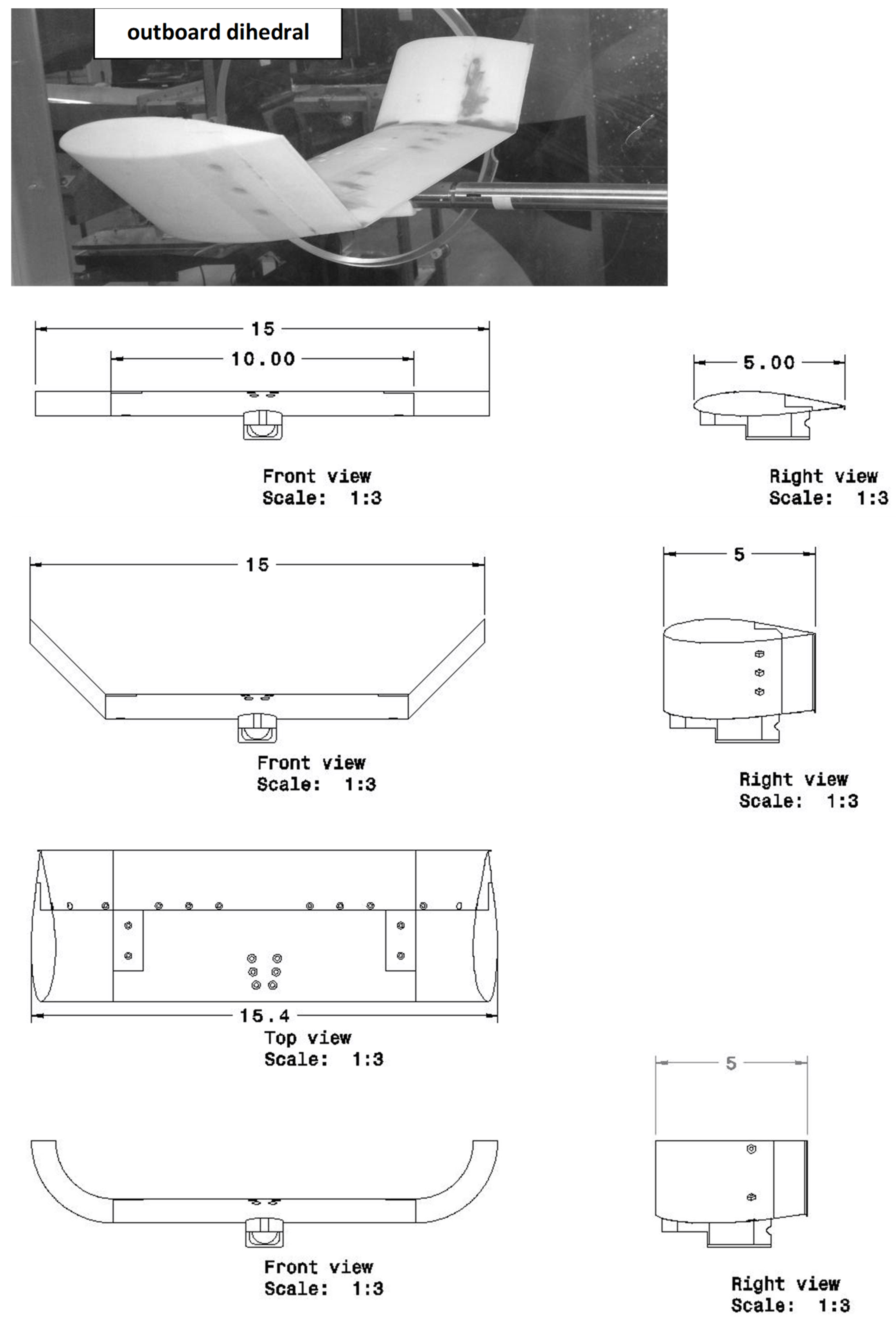
Figure 2.
Effect of GF and non-planarity on CL, data grouped by a) flap extent and b) and outboard section.
Figure 2.
Effect of GF and non-planarity on CL, data grouped by a) flap extent and b) and outboard section.
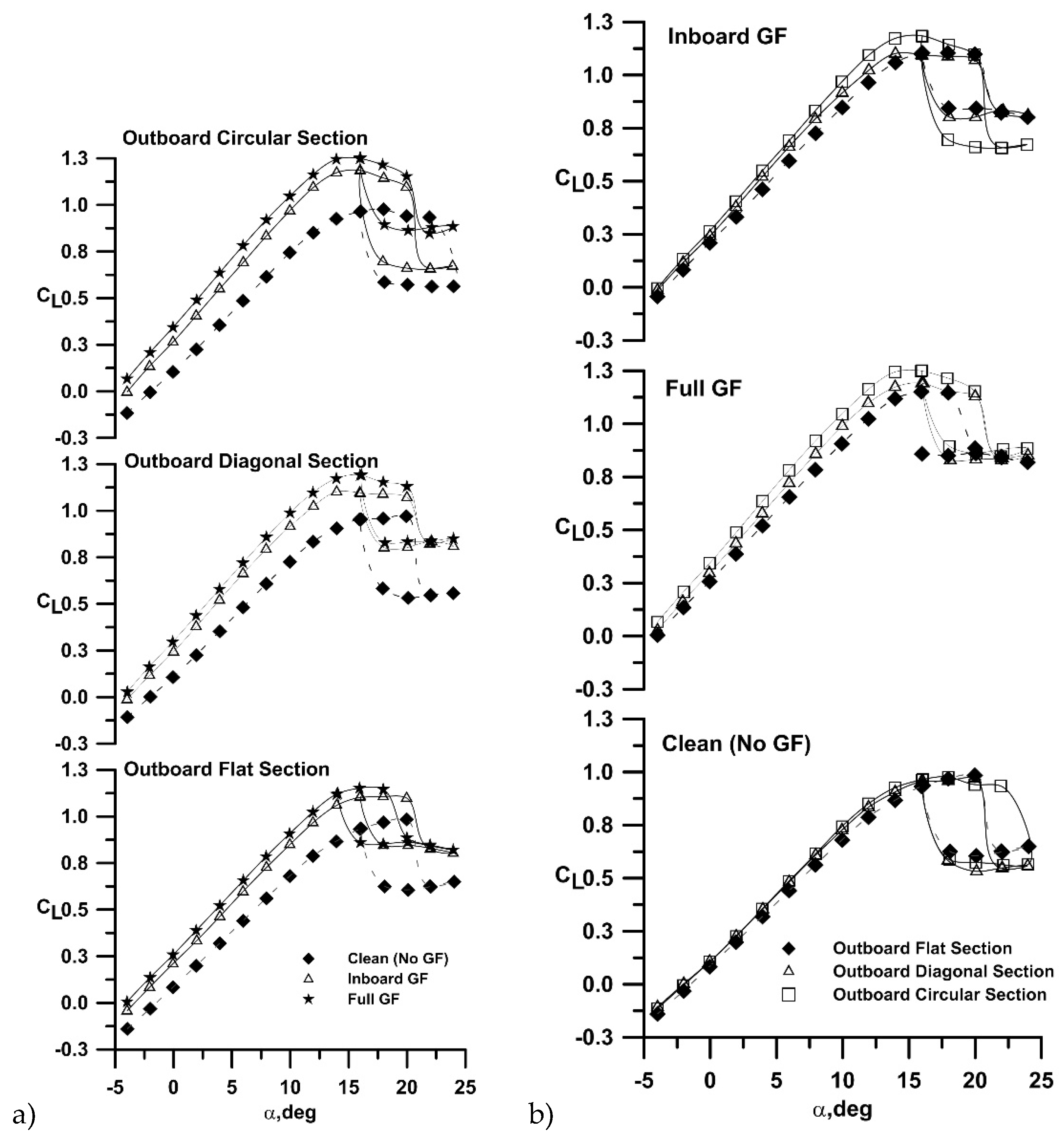
Figure 3.
Effect of flap extent on CL increment.
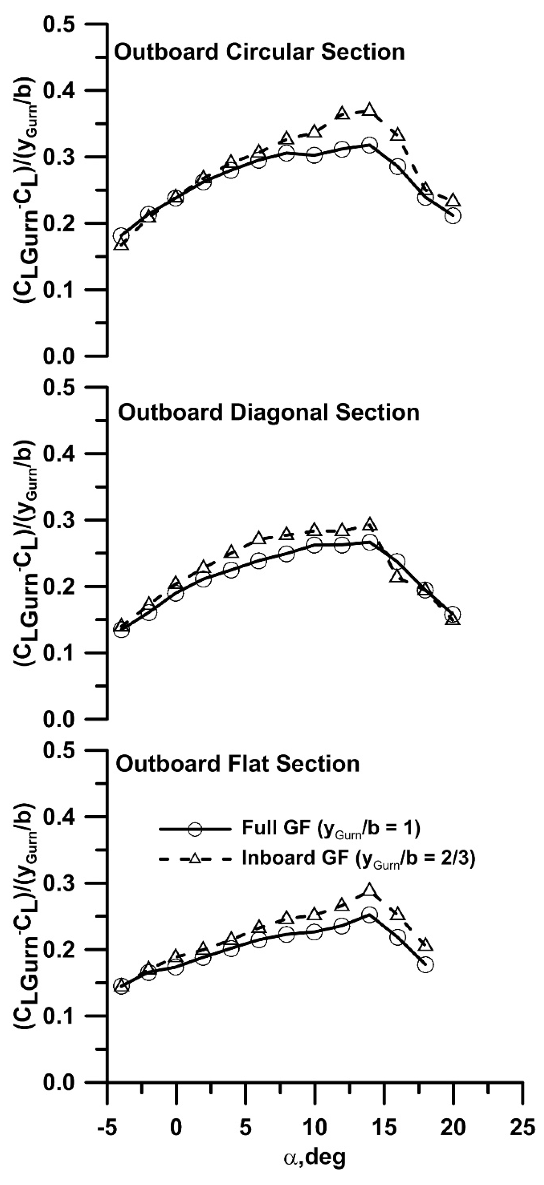
Figure 4.
Comparison of experiment and prediction.
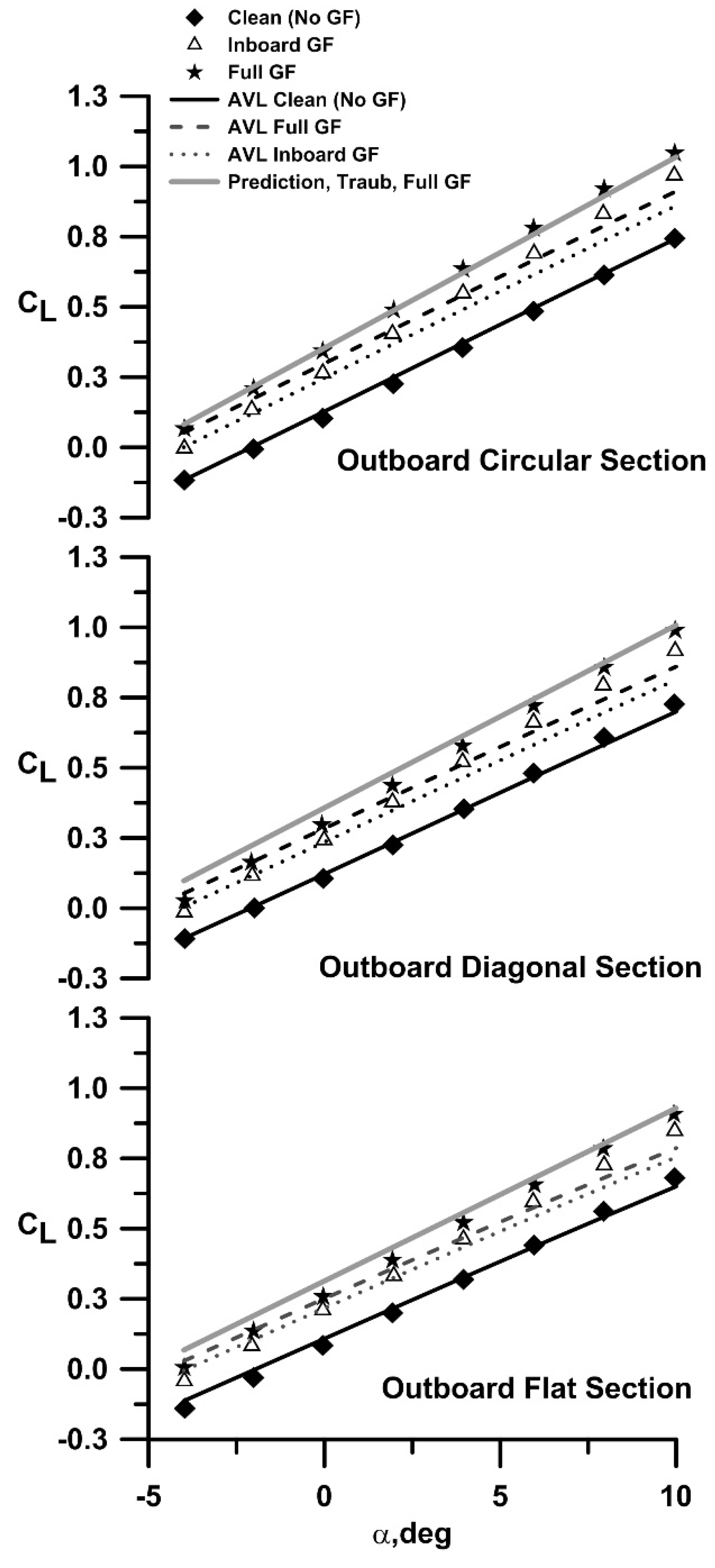
Figure 5.
Effect of GF and non-planarity on CD, a) polar and b) linearized polar.
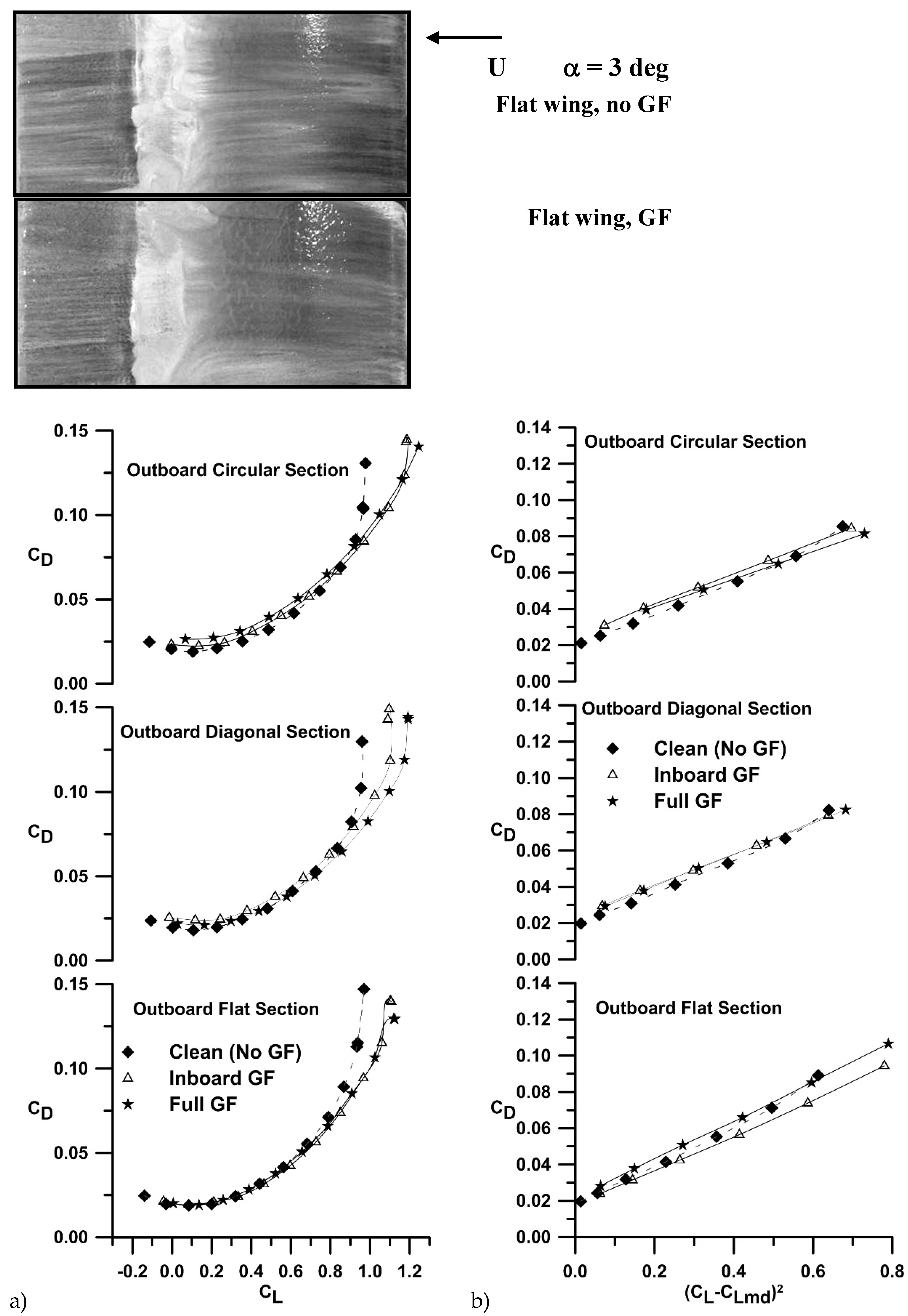
Figure 6.
Effect of GF and non-planarity on CD, a) polar and b) linearized polar.
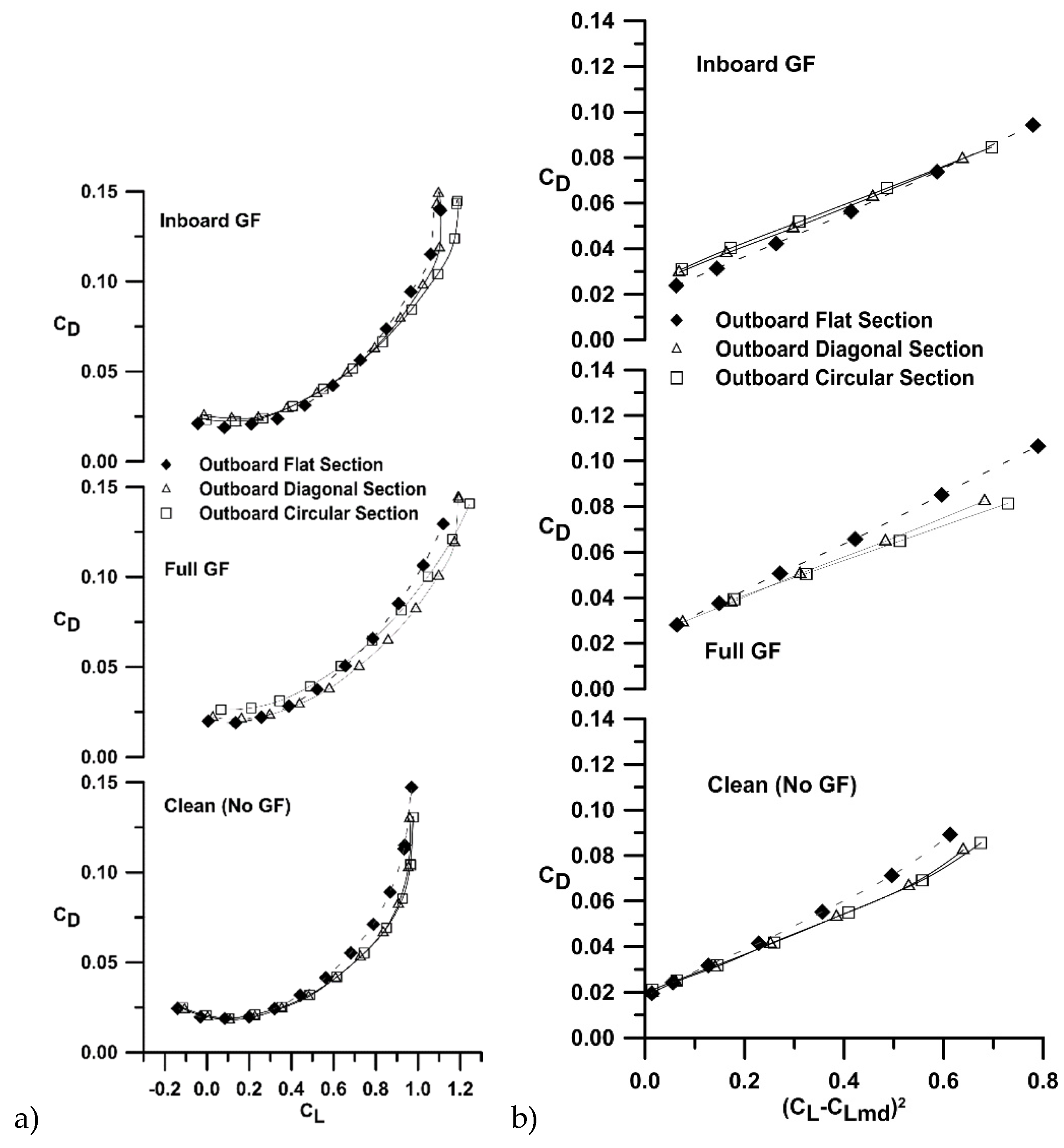
Figure 7.
Drag polar comparison with AVL predictions.
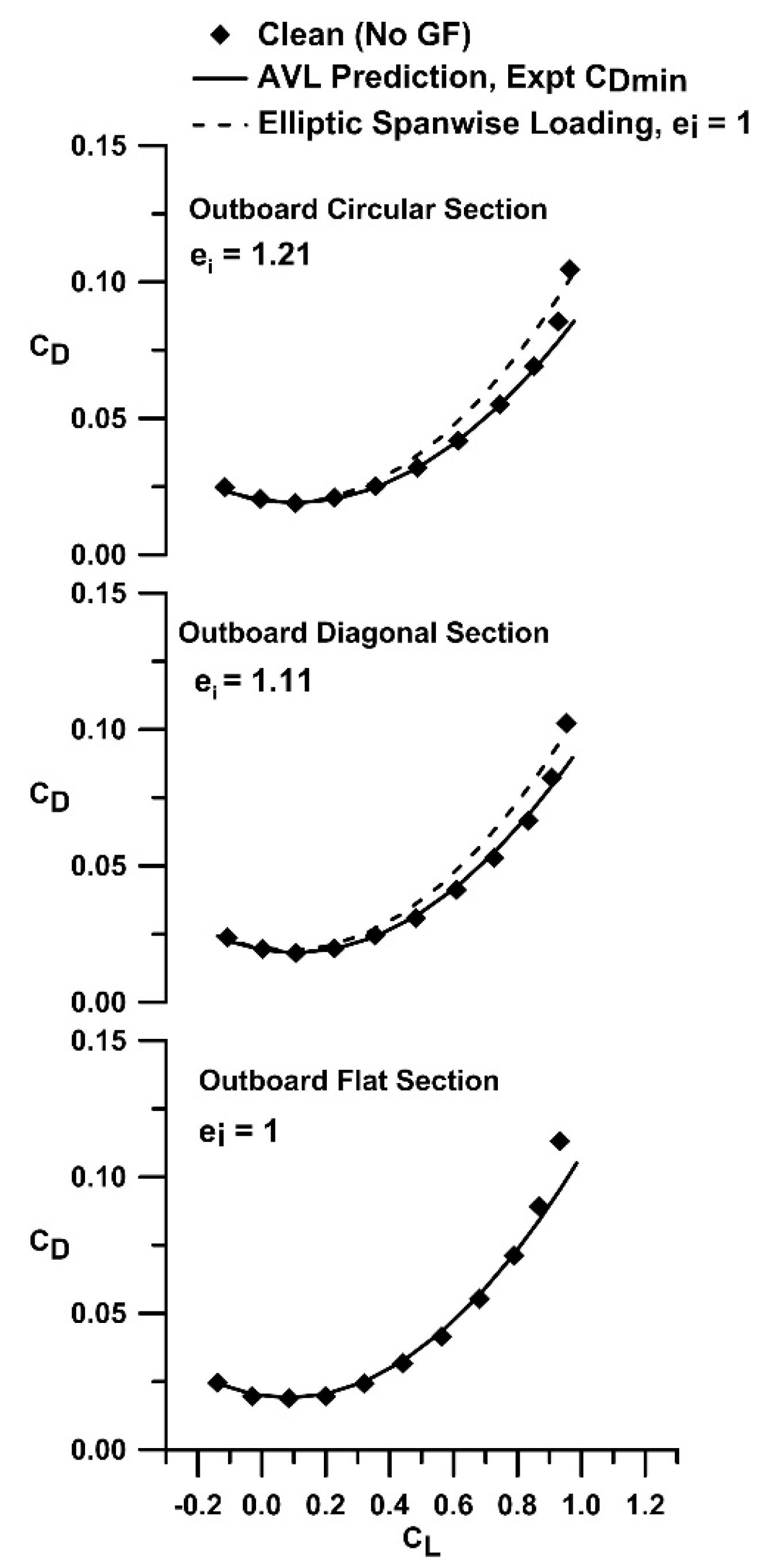
Figure 8.
Effect of equivalent arc length on the drag polar.
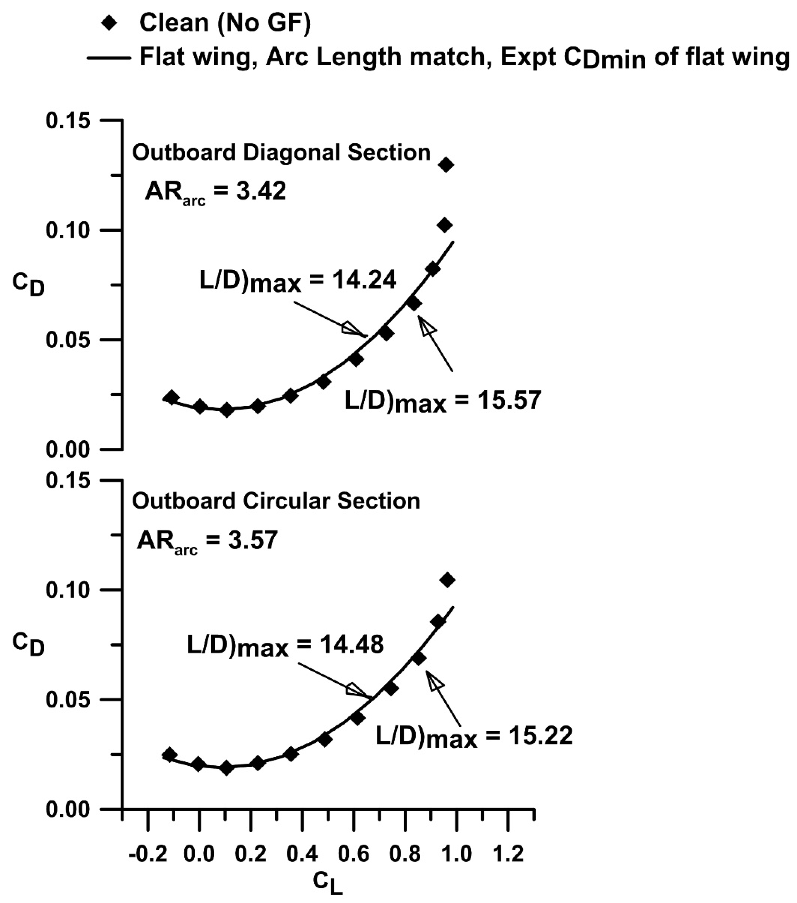
Figure 9.
Effect of GF and non-planarity on CL, data grouped by a) flap extent and b) and outboard section.
Figure 9.
Effect of GF and non-planarity on CL, data grouped by a) flap extent and b) and outboard section.
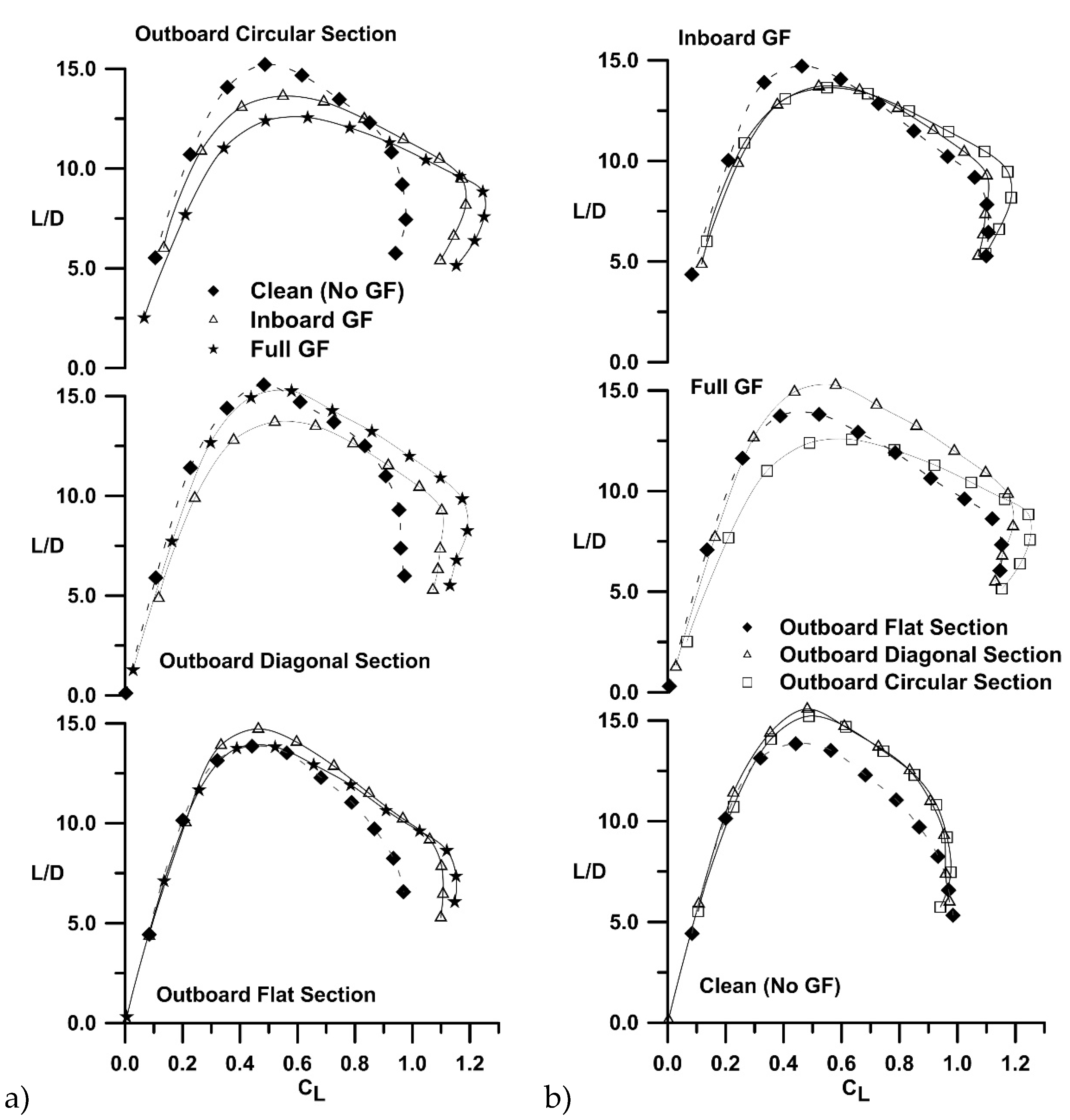
Figure 10.
Effect of non-planarity on the benefit margin.
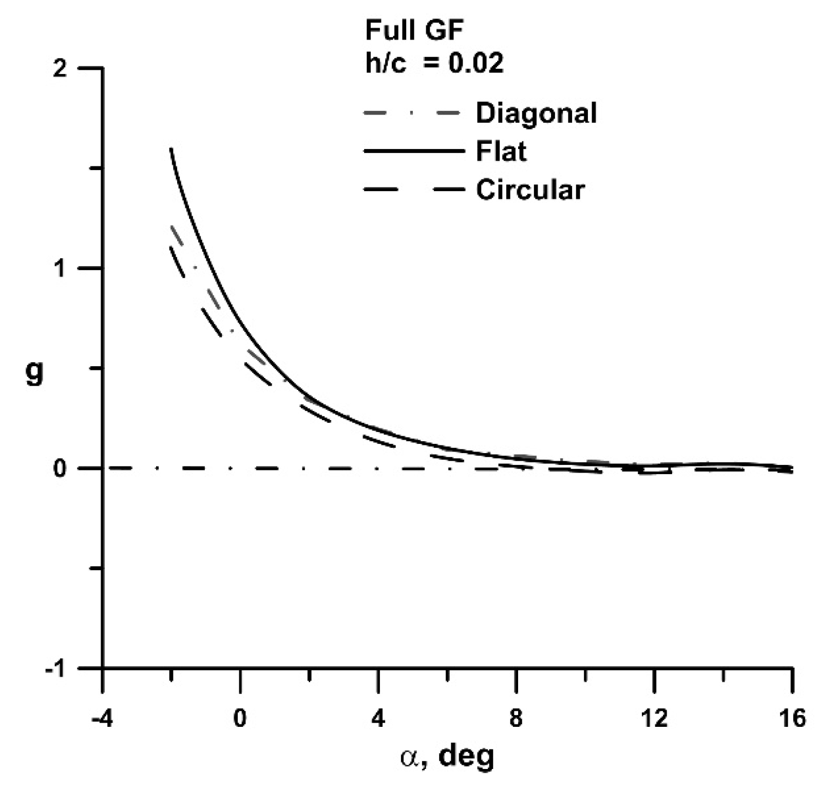
Figure 11.
Effect of GF and non-planarity on CL, data grouped by a) flap extent and b) and outboard section.
Figure 11.
Effect of GF and non-planarity on CL, data grouped by a) flap extent and b) and outboard section.
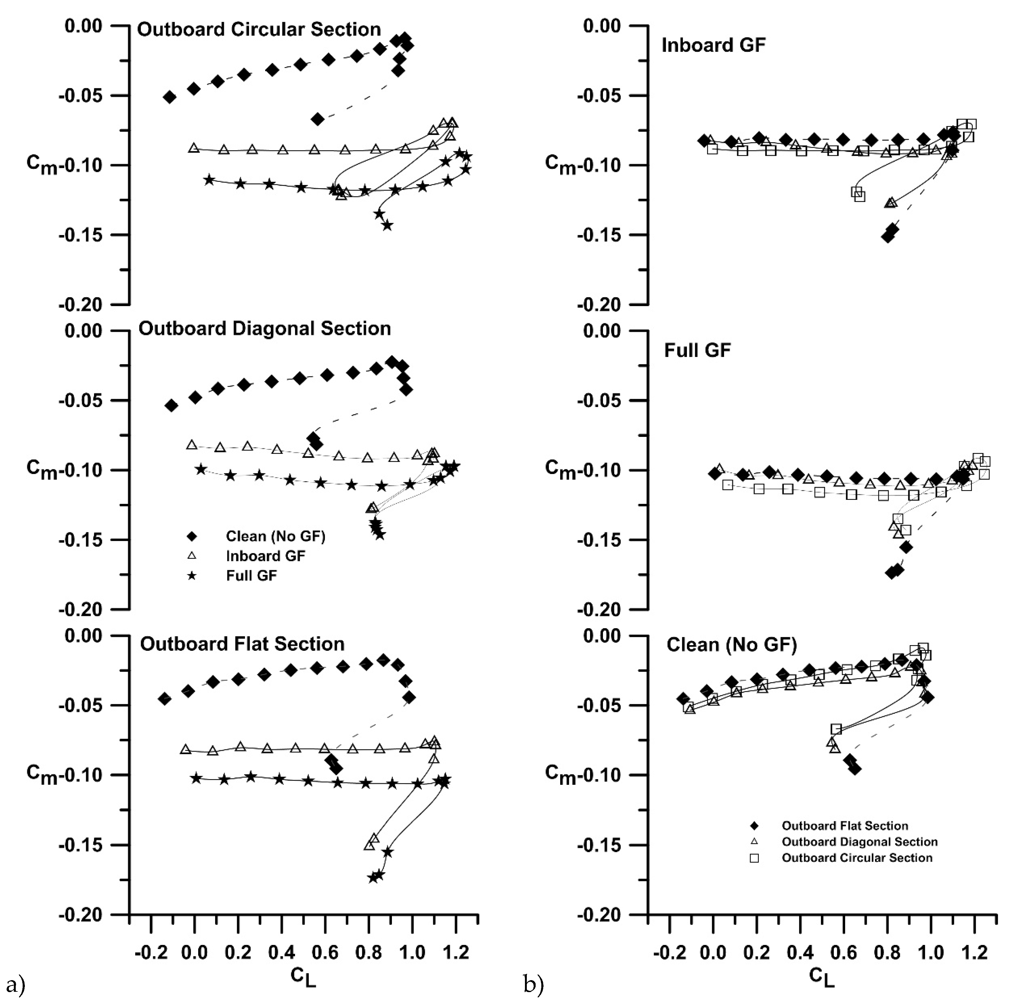

Table 1.
Summary of Experimental Aerodynamic Parameters.
| Geometry | Kp | CL, /deg | CLmax | ZL, deg | a.c./c | L/D)max | CDmin |
|---|---|---|---|---|---|---|---|
| Flat, no GF | 0.112 | 0.059 | 0.965 | -1.53 | 0.23 | 13.86 | 0.019 |
| Flat, full GF | 0.110 | 0.065 | 1.152 | -4.05 | 0.26 | 13.82 | 0.019 |
| Flat, inboard GF | 0.109 | 0.065 | 1.106 | -3.25 | 0.25 | 14.72 | 0.019 |
| Circular, no GF | 0.087 | 0.064 | 0.977 | -1.63 | 0.22 | 15.22 | 0.019 |
| Circular, full GF | 0.078 | 0.071 | 1.250 | -4.97 | 0.26 | 12.56 | 0.026 |
| Circular, inboard GF | 0.086 | 0.071 | 1.185 | -3.77 | 0.25 | 13.63 | 0.022 |
| Diagonal, no GF | 0.090 | 0.062 | 0.972 | -1.86 | 0.23 | 15.57 | 0.018 |
| Diagonal, full GF | 0.088 | 0.069 | 1.190 | -4.40 | 0.26 | 15.26 | 0.021 |
| Diagonal, inboard GF | 0.087 | 0.067 | 1.102 | -3.79 | 0.26 | 13.71 | 0.024 |
Table 2.
Summary of AVL Aerodynamic Data.
| Geometry | ei | Kp | CL, /deg | ZL, deg |
|---|---|---|---|---|
| Flat, no GF | 1 | 0.106 | 0.055 | -2.10 |
| Flat, full GF | 1 | 0.106 | 0.054 | -4.94 |
| Flat, inboard GF | 1 | 0.106 | 0.054 | -4.30 |
| Circular, no GF | 1.21 | 0.088 | 0.062 | -2.19 |
| Circular, full GF | 1.20 | 0.088 | 0.062 | -5.10 |
| Circular, inboard GF | 1.22 | 0.087 | 0.062 | -4.21 |
| Diagonal, no GF | 1.11 | 0.096 | 0.058 | -2.23 |
| Diagonal, full GF | 1.10 | 0.096 | 0.058 | -5.10 |
| Diagonal, inboard GF | 1.12 | 0.095 | 0.058 | -4.21 |
Disclaimer/Publisher’s Note: The statements, opinions and data contained in all publications are solely those of the individual author(s) and contributor(s) and not of MDPI and/or the editor(s). MDPI and/or the editor(s) disclaim responsibility for any injury to people or property resulting from any ideas, methods, instructions or products referred to in the content. |
© 2024 by the authors. Licensee MDPI, Basel, Switzerland. This article is an open access article distributed under the terms and conditions of the Creative Commons Attribution (CC BY) license (https://creativecommons.org/licenses/by/4.0/).
Copyright: This open access article is published under a Creative Commons CC BY 4.0 license, which permit the free download, distribution, and reuse, provided that the author and preprint are cited in any reuse.


