Submitted:
08 June 2024
Posted:
11 June 2024
You are already at the latest version
Abstract
Electric propulsion systems have emerged as a disruptive technological approach towards achieving sustainable and climate-neutral aviation. To expand the operational envelope of such propulsion units in terms of altitude and velocity, an enclosing duct and counter-rotating rotors to enhance efficiency can be utilized. In this study, an iterative CFD-based design tool developed for these novel propulsion systems is utilized to design a reference engine. A substantial reduction in discrepancies between initial specifications, subsequent CFD simulations, and experimental investigations compared to conventional design tools relying on empirical formulations can be demonstrated using a classic rotor-stator configuration. This allows the CFD-based tool to be validated for designing scalable counter-rotating fan engines. Furthermore, to facilitate the transferability of research on such propulsion systems, a validated manufacturing process for composite blades is presented. This effort aims to make state-of-the-art technology accessible to smaller research projects, promoting the widespread adoption of electric propulsion technology in the aviation sector.
Keywords:
contra-rotating propulsor
; CFD-based design tool
; composite fan blades
; electric fan engine
1. Introduction
By 2021, traffic already accounted for of the global direct emissions, despite the influence of the COVID-19 pandemic, with aviation contributing presently [1,2]. Given that aviation falls into the category of "hard-to-abate" sectors in terms of emission reduction, its share of the overall emissions is expected to reach within the next two decades [3]. This anticipation is magnified by current research results indicating that aircraft emissions’ impact on the anthropogenic greenhouse effect should be weighted two to three times higher than that of ground-based transportation due to the high-altitude operation [4,5,6]. Despite a partial shift of passenger volume towards more efficient modes of transport, such as trains for short- and medium-haul distances, an additional annual increase of approximately in transport volume is anticipated for the upcoming years. Due to the contrast to the incremental improvement of fuel consumption per seat of current gas turbine engines, which is projected to increase slightly from to only by 2034 [7], it becomes imperative to consider disruptive approaches like full-electric or hybrid concepts to achieve the ambitious goals of the Flightpath 2050 or the European Green Deal [8,9]. Though these innovative strategies have already been demonstrated in general recently [10,11], they demand a substantial increase in gravimetric energy and power density to enhance competitiveness. However, they might offer several advantages, such as enabling synergies between the engines and other aircraft components. For instance, the integration of distributed, high-dynamic propulsion systems can lead to reductions in the size and resulting drag of control surfaces.
Regarding the actual propulsor, most current research is focused on replacing traditional propeller drives of general aviation aircraft with electric motors. Since electric aircraft are also mainly evaluated based on economic and operational criteria, achieving high flight speeds is crucial for most scenarios. In response to this, a ducted, contra-rotating electric fan engine is being developed and investigated within the project ELAPSED (Electrified Aircraft Propulsion – safe, efficient, digitally linked) as a part of the digitalization and technology research center dtec.bw of the Federal Armed Forces of Germany [12]. This innovative approach can be a response to the expectation that the demand for electric aircraft engines is expected to surpass the typical flight speed range of propellers. To expand the operation range beyond their limit of low to medium flight Mach numbers, a ducting system along with a high total pressure ratio across the fan stage of the propulsor is applied instead. The increased specific thrust enables small cross sections, typically prescribed by the aircraft concept anyway, and compact engine designs, crucial for high flight speeds as the drag increases quadratic with the speed. Furthermore, powering such a fan system by electric motors the application of contra-rotating stages become a feasible option to increase the efficiency, investigated within the project but not considered here initially.
Returning to the already discussed required increase in power density, the application of lightweight structures like composite blades made of carbon fiber reinforced plastics (CFRP) offers tremendous potential. While this technology already represents a state-of-the-art solution for large engines, for instance within the GE 90 [13], it has seen limited application in the academic and research-intensive context due to the increased manufacturing complexity. To enhance the transferability of research findings, especially regarding the areas of heat management of electrified aircraft engines or the application of active tip clearance control systems, a less labor-intensive manufacturing process for composite fan blades will be developed and validated by combining various innovative approaches, including tensile testing.
Besides, as already introduced previously in [14], an innovative design tool for ducted, electric fan engines was developed within the project. Common preliminary design tools are typically based on empiric formulations that are most often valid for a certain input range only. For instance, Carter’s rule [15,16] and extensions built upon this foundation [17,18,19] are typically applied to account for deviation angles in axial turbomachinery. However, these parametrized formulations are limited to a certain range of their input parameters and most often valid for large engines. Therefore, their application for smaller engines like within the scope of this project, for instance required for the already discussed distributed propulsion concepts, cause significant deviations between the initial engine specification, on the one hand, and the CFD calculations as well as the experimental results on the other hand. In contrast to blades having a large tip to hub ratio, the outflow of the small blades designed here is dominated by -effects that seem to be not properly incorporated into the empiric formulations. Within a former project, such an empiric correlation-based design tool was developed at the institute and utilized to design an electric, ducted engine. However, the experimental investigations confirmed relatively large deviations between the initial specification and the subsequent CFD simulation and experimental investigation [20,21,22]. To enable the accurate design of freely scalable drives, the application of the empiric correlations is replaced by the incorporation of CFD. Since the computing power increased substantially during the last years, for instance by the introduction of high-performance clusters also at universities, this approach became a feasible option for preliminary design tools as shown here as well. Nevertheless, the effort, as expected, is larger for designing the engine due to the iterative character.
Summarizing, two major research questions are to be answered in the following: First, is it possible to validate the design tool by a manufactured engine? Can it be verified, that the CFD approach, as anticipated, increases the accuracy and reduces the deviations between the initial specification and the numerical as well as the experimental results? And second, can a feasible manufacturing process for composite blades be found and validated? Whereas it has to be suitable for an application within a research context at universities where both the financial resources and the manufacturing capacities are strictly limited, it must not compromise the tool validation nonetheless.
2. Methods
The design tool, initially introduced in [14] and further explained with the example below, should be verified and validated by designing a reference propulsion system (RPS) and its subsequent experimental investigation.
2.1. Application of the Developed Tool to Design a Reference Propulsion System
In order to focus on the tool’s functionality, the RPS contains a common rotor-stator stage. However, the functionality of the design of various sub-components like the composite-blades, the disk, the adjustable nozzle, or the -printed standard inlet should be verified within the RPS to enable their similar application within the future innovative propulsion system (IPS), having a contra-rotating stage. Besides, this reduces the complexity of the validation process of this initial step as the total pressure distribution has to be measured and compared at a single engine stage only compared to the two positions after each rotors of the IPS later.
In principle, the automated tool chain, shown in Figure 1, is based on an iterative, CFD-based calculation of initially unknown parameters like the rotor’s isentropic compressor efficiency or total pressure losses over inlet, stator and nozzle.
The inputs into the tool can be split up into the two categories performance and design parameters. Due to the tool’s iterative character both categories contain not only fixed parameters but also values that require initial assumptions at the beginning, replaced by CFD results for later iterations. The main entries of the first category and their chosen values for the RPS design are summarized in Table 1 and discussed in the following.
The actual calculation part of the tool chain mainly consists of three parts, indicated by the individual orange boxes on the right hand side of Figure 1. Within a numeric computing environment the first step is to determine the general design of the various components like the blades, standard inlet, casing, or nozzle. By a mean line approach the values of (total) pressure and (total) temperature are calculated from the performance parameters, among others from the total pressure ratios . They relate the total pressure conditions before and after a certain component. For instance, the fixed total pressure ratio over the rotor specifies the ratio of the total pressure at the rotor’s outlet to its value at the inlet, indicated by the subscripts and , respectively, as follows:
The total pressure losses over inlet, stator and nozzle, given by the respective total pressure ratios , and and defined similar to that of the rotor, enable the determination of the total pressure at all engine stages. However, as indicated in Table 1 they have to be determined iteratively by the CFD later in contrast to the fixed value of . The flight Mach number, , results from the planned tool validation by a static engine operation within the test bed set up at the institute. Together with an altitude specification, the inlet total pressure and temperature as well as the static outlet pressure are set, based on the International Standard Atmosphere [23]. By the assumption of an adiabatic inlet, stator and nozzle and by incorporating the isentropic efficiency the total temperature at all stages can be determined, too. The difference in total temperature over the rotor is used, in terms, to determine the required specific work for the specified total pressure ratio. Together with the available motor’s shaft power and further specifications like axial flow Mach numbers at different stages or hub radii this allows the calculation of the engine’s mass flow and general radii. Afterwards, Euler’s turbine equation is utilized to calculate the required flow deflection from the determined specific work and rotation speed input . Finally, a radial equilibrium is implemented to calculate the flow angles not only at the mean line radius but also at all other radial positions.
The value of chosen for the total pressure ratio facilitates a comparability to current developments of electric, ducted propulsion systems. In contrast to fans of state-of-the-art aircraft engines, reaching values up to , it appears to be relatively low. However, this enables, in terms, relatively low rotation speeds without avoiding undercutting recommendations like a DeHaller number across the entire span. Subsequently, the strength requirements regarding the blades are relatively low in the first place for the RPS to gain experience for scaling it later within the IPS. The stage inflow Mach number at the engine’s mean line had to be found as a trade off between the mutually from this Mach number dependent number and radial blade length. The minimal number of occurs at the hub, increasing to at the mean line and at the shroud, based on the mentioned radial equilibrium approach and the chosen free vortex design principle. Due to the low Mach numbers set inside the engine and the low total pressure ratio a high isentropic efficiency and small total pressure losses within inlet, stator and nozzle could be found iteratively. The range of the motor’s shaft power was chosen with regard to the maximum output power of the installed power supply within the test bed of . Besides, it includes margins for testing at speeds larger than design point speed and the estimated losses within the motor and its electronic speed controller (ESC).
Whereas the performance parameters rather describe the actual engine cycle, based on the flight mission and deployment scenario, the group of design parameters contains specifications that finalize the engine’s design within the first part of the design tool, affecting the engines performance. The most important parameters of this category are summarized in Table 2.
In contrast to the iterative performance parameters, representing global specifications, the iterative design parameter deviation angle must be specified for the three radial positions j meanline (), hub and shroud. All radial positions in between are linearly interpolated to find . Their values must be iteratively adjusted so that the initially specified, global performance parameter total pressure ratio and its corresponding total pressure increase over the rotor are achieved within the subsequent CFD simulation. The actual metal angles of the blade’s NACA 65 profile [24] are increased from the original calculation, based on Euler’s turbine equation and the radial equilibrium, by the found angles . The fixed parameters of this group are, apart from the tip clearance TC, based on findings of other, similar research activities. For instance, the number of the rotor blades and the respective inverse of the solidity, , the axial spacing between the rotor and stator and the maximum relative blade thickness were chosen following the results of systematic experimental and numerical variations in [25,26,27]. Though all those investigations were made on contra-rotating stages the findings were nevertheless adopted here to test all the designed engine components by a geometry close to that of the future IPS. To account for the varying deflection over the span the solidity is adjusted by towards hub and shroud to increase efficiency. Besides, the relative thickness is increased from shroud to hub to account for the increasing load. Since the manufacturing quality and, subsequently, the operational behavior of the blades was not known yet during input parameter specification, the tip clearance was chosen relatively large to . For optimal results, all fixed values of both performance and design parameters would have to be varied, too, to find an optimal design. However, as for the RPS design the validation of the tool is of utmost importance and not the optimization of the engine’s performance itself, the parameters were not optimized at this point.
The general geometry, calculated within the actual iteration’s first step from the input parameters, is subsequently utilized in a 3D mechanical solid modeling design software to generate the actual 3D components. This includes not only the actual blades of the rotor but also casing components like the nozzle or the standard inlet in accordance with VDI ISO 5167 [28], taken over into the CFD analysis afterwards. For a more detailed description of the geometry calculation refer to the previous publication in [14].
Within the third step, the engine’s performance is investigated by a steady-state CFD simulation, focusing on the iterative parameters. In order to reduce the calculation effort, a single blade passage, created as negative from the CAD components, is modeled by allying rotational periodicity at the domain boundaries in circumferential directions. Four stationary domains for inlet, stator, nozzle, and outlet as well as one rotating domain for the rotor are set up. The inlet includes an additional volume ahead of the actual beginning of the standard inlet, having an axial length and diameter of two and four times of the rotor’s outer diameter, respectively. Similar, the outlet enlarges the blade passage by the simulation of the free flow after the nozzle where this volume has an axial length and diameter of three and four times the rotor’s outer diameter.
Besides, the nozzle’s outer flow is included by enlarging this outlet domain upstream from the actual nozzle’s outlet plane. At the interfaces between the domains itself, the mixing plane approach is used by defining the corresponding pitch angles in dependency of the number of rotor and stator blades. Within the rotating rotor domain, the shroud’s wall is set up as contra-rotating as it does not rotate with the rotor. In contrast, the hub is included as rotating wall. To account for friction effects, the no slip wall approach is utilized for all wall boundaries. Besides, all walls are set to be adiabatic. The application of inflation layers on all surfaces including the in- and outlet ensures a normalized wall distance to include boundary layer effects. In addition, the mesh is refined at all of these surfaces and turbulence is included by the Shear Stress Transport (SST) approach. All outer boundaries are specified by the entrainment and opening pressure and temperature option to define them either as total or static values, depending on weather the surface is flowed through into or out of the domain. Finally, the engine speed is set by the angular velocity of the rotor domain. During the actual iterative design process of the RPS, the compressible Reynolds-averaged Navier Stokes Equations, implemented in Ansys CFX, are solved for a steady-state solution and the different variables like total pressure ratios or efficiencies are determined mass flow averaged in accordance with the implemented calculations used for the design tool. Returning to the iterative adjustment of the design parameters discussed above, the upper part of Figure 2 visualizes the iterative adjustment of the deviation angle. Since the rotor was designed in accordance with the free vortex design principle to receive a constant increase in enthalpy over the span, the required fluid deflection at the hub is much larger than that at the shroud to balance out the lower circumferential speed of the blade at lower radial positions. Therefore, significant deviations between the desired and within simulated flow angles can be detected, especially close to the hub, resulting in a reduced increase in total pressure calculated by the CFD. As discussed above, in common design tools the attempt to avoid this is the application of empiric correlations to determine the required corrections of the blade’s trailing edge angle. In contrast, within the design tool approach discussed here the three local deviation angles are adjusted from iteration step to step as plotted in the upper part of Figure 2 in accordance with the results shown in Figure 2. Initial values were taken from the IPS design presented in [14]; due to design differences like other solidities the final values differ. The minimization of the local deviations results in decreased deviation of the global specifications of the total pressure increase as shown in the lower part of Figure 2 by the black curve. The deviations p of the other iterative, global performance parameters are calculated between the result of the actual and the previous iteration step, representing a rate of change. Similar to the resulting green curve of the deviation of the isentropic efficiency plotted within the lower part of Figure 2, these rates decline with increasing iteration step. After the iteration all deviations of the global performance parameters undercut the chosen abortion criterion of . The final RPS geometry of this iteration is shown as CAD rendering in Figure 3.
Typically, the results of a simulation depend on the quality of the applied mesh. Based on the previously mentioned requirement to undercut an value of 4 on all surfaces, the first layer thickness of all inflation layers was set to . In order to find suitable values for the general and the refinement element size, a systematic mesh convergence study was carried out, based on the Richardson Extrapolation [29]. The described blade passage was simulated by three different meshes at design speed; the results are summarized in Table 3.
All meshes are geometrically similar as the refinements and inflation layers were placed in all cases on all surfaces. As prescribed in [29], an averaged volume element edge length h is calculated from the element number and total volume of the blade passage, used to ensure the meshes are refined by at least a factor of . For the convergence study the simulated values of total pressure increase , mass flow and isentropic rotor efficiency were considered. In contrast to the iterative design process, focusing on achieving the specified total pressure increase over the rotor , the experimental setup allows the measurement of the total pressure increase from ambient to the rotor’s outlet plane only. Though this is explained in detail below in the context of the test bed description, this enlarged value is taken into account here already, indicated by the subindex 0. In the order mentioned above, the apparent orders p of , and result for the considered outputs. Due to the small relative errors and of the second simulated mesh, related to the finest mesh 3 and the extrapolated results, respectively, a further reduction of the element size did not seem to be meaningful. Besides, not only steady-state simulations of the blade passage in design point operation are carried out as for the iterative design process. Instead, the performance map of the engine is calculated by transient simulations to consider unsteady behavior, especially during throttling. These transient simulations require the simulation of two adjacent blade passages of all domains except for the stator. Since the number of rotor blades is nearly twice the number of stator blades, this ensures the required pitch ratio close to unity at all domain interfaces. Therefore, the number of elements for those transient simulations is approximately twice the number stated in Table 3. To find a trade-off between solution accuracy and computing effort, the second mesh was chosen for the later performance map simulations, resulting in slightly increased errors but halved element number compared to the finest mesh.
However, not only the local discretization but also the discretization in time has to be reviewed for transient simulations. It is specified by the simulated number of time steps per passing period which, in terms, describes the duration of a rotor blade passing the following stator blade. Apart from the doubled blade passages for the majority of domains, the interfaces between the domains are changed to transient rotor stator for these simulations. Besides, the steady-state simulations are aborted if all root-mean-square residuals undercut a value of . For the transient calculations, the following two criterions have to be reached instead in accordance with typical recommendations for transient simulations. First, the arithmetic averages of the calculated mass flow and total pressure ratio over two intervals, one equaling a total, the other one a half revolution of the rotor, are within a relative tolerance. Second, the coefficients of variation of the same two outputs, calculated from the standard deviation divided by the mean, both considered over a whole revolution, have to be within a certain relative tolerance, too. Adjusted for the case considered here, the solutions can be considered converged if a tolerance of is undercut by both criterions where the final outputs were calculated as mean of the entire last revolution. Finally, for the selection of a suitable number of time steps per period not only the result accuracy was reviewed but also weather nearly all time steps of the final revolution undercut the same residual target of like the steady state solutions. Three different numbers of time steps per period were considered as summarized in Table 4.
Similar to the discussion of the local discretization above, relative errors of the same three outputs, referred to the finest simulation of the third case, were calculated. Since unsteady behavior is of relevance when simulating throttled behavior, not only simulations with the design nozzle but with a reduced outlet area to were considered here, too. Again, a trade-off was found in the second option of five time steps per period as the deviations to the third case are small compared to the doubled computing effort.
Overall, it could be demonstrated that, as expected, the deviations between initial specification and CFD recalculations significantly decreased by directly incorporating CFD instead of relying on empirical formulations, while the effort increased due to the iterative nature. However, a final evaluation of the entire tool chain will only be possible during the experimental validation phase below, incorporating the influence of the composite manufacturing. To reduce the number of iterations, simple correlations could be implemented to obtain better initial values. Additionally, while reaching the global convergence limit is possible, adjusting only three radial positions seems insufficient to achieve the desired pressure rise across the entire span range. Especially for the design of the future contra-rotating propulsor, local flow distortions would be critical, as they could lead to local flow separations at the subsequent second rotor. Therefore, the number of radial adjustment points should be increased. Based on the discussion of the discretization in time a simulation option was found that seems to be suitable to calculate the entire performance map of the engine. Since the deviations between the steady-state and transient results account to , and regarding the result of total pressure increase, mass flow and efficiency, the transient simulation seems to confirm the steady-state results. As, in addition, the computing effort is similar, a transient simulation could be used for future iterative-design processes already.
2.2. Carbon Composite Blades
The final blade and overall engine geometry of the iteration were afterwards transferred into a manufacturable design maintaining the aerodynamic surfaces and geometries. Apart from the composite blades, discussed in the following, the design of further components is summarized later. The most significant advantage of using composite structures lies in the substantial reduction of weight, up to , compared to traditional metallic blades. This reduction enables highly dynamic behavior and enhances the engine’s gravimetric power density. Additionally, there is an increase in the blade’s safety factor and a potential decrease of up to in the maximum relative profile thickness, leading to aerodynamic advantages [30,31]. However, despite these advantages, the widespread adoption of composite blades faces certain challenges. Issues related to repairability and recycling remain open questions. Furthermore, the manufacturing process for composite blades is more complex and labor-intensive compared to traditional milling methods, relying heavily on manual craftsmanship. Consequently, the application of composite blades is currently limited and predominantly reserved for a few large-scale projects.
While research projects of a similar scale to the ELAPSED project are scarce, one noteworthy example is the counter-rotating integrated shrouded propfan (CRISP) project conducted by DLR [32]. This project utilizes a standard structure of the individual composite plies for the two rotors, which deliver a pressure ratio of at mass flow rate of . This employed structure adheres to a typical symmetrical layup of composite plies, allowing for quasi-isotropic properties. It consists of a symmetrical arrangement of 128 plies, following the orientation, forming an organo sheet. This sheet is subsequently subjected to hot forming and machined to achieve the desired contour. The primary load considerations for these blades, however, are radial and torsional stresses. Therefore, within the CRISP project, various approaches to numerically optimize the layup configuration are being explored, enabling a reduction of the maximum displacement by up to [33].
For the ELAPSED project, however, two approaches have been developed to enable the adoption of this technology in smaller research endeavors. Firstly, the development of a new design tool, as previously explained, has streamlined the direct and automated integration of both composite layers and moulding creation. This represents a significant departure from the previously intricate and time-consuming process of generating these layers and mouldings for existing designs created in different programs. In this context, where the contour or outer geometry of the blade is precisely known in the form of a point cloud and does not need to be separately imported or recreated, the design tool allows for the flexible calculation of the maximum local ply count based on the to be specified ply thickness and maximum relative blade thickness, both being input parameters for the design tool. Additionally, a fundamental layup configuration is embedded within the code. Since a common configuration of individual blades mounted on an inner disk was chosen, the blade consists not only of the actual blade, its upper part, but it includes a blade root as well. This lower part has a front and rear nose that is used to mount the blades into the disk’s lugs.
Exemplarily, the resulting ply structure of the blade’s tip is shown in the left-hand part of Figure 4. It consists not only of the two outer plies, predefined by the aerodynamic surface, but also out of two inner layers on both suction and pressure side, resulting in a total of six layers in its center. Since the blade’s maximum thickness increases towards the hub, the number of plies in the transition from the actual blade to the root accounts to 12. As shown in the center of Figure 4, all layers do not end at the transition to the root but are wrapped around a carbon fleece utilized in the root. The layers are finally unwrapped within the CAD software to receive the individual ply shown on the right-hand side of Figure 4. All these steps described so far are included in the design tool described above and are processed automatically.
The second approach developed in this context involves the utilization of cutting-edge stereolithography (SLA) printing technology. Due to the intricate blade geometry, conventional composite manufacturing methods such as autoclave production were not feasible options. Instead, the design tool automatically generates five moulding parts. Apart from the two main parts for both pressure and suction side, based on the blade geometry similar to the creation of the individual plies, three further parts are used for the blade’s root. To replace the costly and time-intensive milling procedures in the production of these mouldings, several printing options were explored. However, due to the requirement for a smooth surface finish, fused deposition modeling (FDM) printers did not meet the criteria. Instead, SLA printers were employed, reducing the labor involved in moulding production significantly as no further manual post-processing is required. The mouldings for the reference propulsion system blades were still produced using glass reinforced resins. This material meets the strength requirements for moulding pressing but exhibited high brittleness. Consequently, the mouldings could only be used 2-3 times, and occasional chipping from the mouldings resulted in rejected blades. However, through systematic variation of post-curing duration and temperature on newer and even more cost-effective resins, followed by tensile and notch impact tests, the ductility and maximal elongation could be increased significantly by factor five, even offering a smoother surface finish. The initial version with mouldings printed by an FDM printer, resulting in the uneven surface discussed above, compared to the final version of an RPS blade with a smooth surface, is presented in Figure 5. Since both blades are not used within the rotor their small flaws on the surface are not post-treated by filling them with a mixture of resign and ground carbon fiber.
Several tested prepreg materials did not yield satisfactory results because of the small radii within the transition zone. Instead, traditional dry twill fabric is employed. It is impregnated with the infusion resin MGS RIMR426, cut to match the plies discussed earlier, and positioned into the mouldings via hand-laminating. To accommodate torsion, the outermost plies are oriented at , while all inner plies are oriented at relative to the radial direction. Subsequently, the five-part moulding is pressed together, and the blade cures initially at room temperature before being relieved out of the mouldings and tempered by for another hour. Due to the anisotropic material behavior and the consequent need to model the individual plies and their interaction in an FEM analysis, such structural analysis regarding elongation and strength is considerably more complex compared to metallic materials, for example. Consequently, for the RPS, which experiences relatively low loads, this analysis was omitted and the already discussed ply orientation was chosen based on the findings in [33]. Instead, the tensile tests discussed below are intended to be used in the future for validating such a detailed FEM model. This validated model will then be employed to calculate the significantly more heavily loaded blades of the IPS prior to their production. However, different post-curing conditions of the blades were tested, resulting in the optimal tempering discussed above.
Apart from the eleven blades produced for the actual rotor, eighteen further blades were manufactured. Those were used, on the one hand, for initial tests regarding the printer selection, based on the achievable surface smoothness. On the other hand, they were used for the following tensile and bending tests, including a variation of the blade’s curing conditions. Since the overall production time could be reduced to 2 hours per blade, this process seems to be an applicable option within the university’s context. However, the rotor should be used to validate the design tool. Consequently, any geometric deviations from the CAD could prove critical, potentially leading to discrepancies in behavior compared to the CFD calculations. Compared to the target maximum thickness of at the blades’ tip, the respective mean value measured accounts to having a standard deviation of . Besides, the chord is measured to at the blade’s tip with a standard deviation of whereas the target was . This will be revisited during the tool validation later. To compensate for inequalities in the radial length of the blades the entire rotor with the finally assembled blades was machined down to the desired outer radius in one step, with the radius determined based on the tensile tests and commissioning tests discussed in detail below. In addition to ensuring geometric reproducibility, which could thus be guaranteed, reproducibility of blade mass for balancing is crucial for rotor operation. Therefore, at least a static balancing could be carried out successfully ensuring that the rotor’s center of gravity lies within the engine axis. A balancing mass was applied under the base of all blades scheduled for the rotor operation after curing. This mass consists of the same resin material already used for the actual plies but was reinforced here with ground carbon fiber. Subsequently, material was removed from the balancing mass again using a precision scale having an accuracy of , resulting in an average blade mass of with a very low standard deviation of .
As previously mentioned, the tip clearance between the blade and casing at design point speed is one of the input parameters for the design tool. While a smaller value enhances the blade’s performance by reducing reverse flow and swirl effects, a certain margin must be maintained to prevent grinding of the blades at the casing, for instance during maneuvers resulting in unexpected blade elongation effects. Given the anticipated relatively high E-modulus for composite blades, a moderate of has been selected. However, due to the radial loads caused by rotation, blade tip grinding is necessary to establish a specific at , which then reduces to the chosen with increasing engine speed. The blade elongation causing the reduction in tip clearance depends mainly on the material’s Young’s modulus E. Since composite belongs to the category of anisotropic materials, its Young’s modulus in a particular considered direction, in this case the radial direction, is heavily influenced by the layer sequence and structure. Unlike isotropic materials, performing an FEM calculation to determine the anticipated elongation is projected to be quite resource intensive. Furthermore, since this approach necessitates subsequent validation owing to the multitude of boundary conditions that need to be set, this step is omitted. Instead, the blade’s performance is experimentally validated both by tensile and operational tests, discussed in the following, and the findings are leveraged to determine an expected blade elongation and a suitable .
As a basis for defining an appropriate testing procedure, a calculation of the expected blade loading is carried out. The blades are exposed to the centrifugal and aerodynamic forces. While the latter load is indicated by the subindex , a subindex for indicating centrifugal forces is omitted in the following for the sake of improved readability. First, the centrifugal force F caused by the actual blade is calculated, excluding the root since it is clamped into the disk. At any radial position between hub and shroud, and , respectively, the effective force can be determined by integration as follows:
The blade’s cross section varies across the radius and is therefore set by the CAD data. Besides, a constant density across the entire blade is assumed, calculated from the measured mass and the model volume. According to this approach, the maximum centrifugal force occurs at the transition into the foot:
where the angular velocity corresponds to the design point speed of . With increasing radius it diminishes, reaching zero at the blade’s tip. Though, in contrast, the aerodynamic axial force of at design point, determined from the CFD simulation, is much smaller, the blade behavior under this load is experimentally tested, too.
Since the samples are not standardized, the testing procedure for the tensile test must be conducted in accordance with DIN EN ISO 527-5 [34]. To facilitate the experiments in academic research, this test setup was chosen as it is designed for a universal testing machine capable of operating in both tension and compression directions. The model used here for both tests is the inspekt table 50 kN by Hegewald & Peschke. It features wedge-screw grips on both the lower fixed and the upper movable traverse. The lower clamping of the blade is achieved by using a two-part holder, similar to the engine’s disk, which is bolted to the lower traverse. An adapter for the upper traverse is utilized to avoid torsional moments on the blade caused by its twisted geometry. To clamp the curved and twisted tip surface using the jaws of the clamping tool, flat outer surfaces of the elements used to apply the forces are required. To mill the negative profiles of the blade’s pressure and suction side, the manufacturing of these elements as depicted in DIN EN ISO 527-5 is only partially feasible. Instead, their thickness had to be increased and the use of cross-laminated glass-fiber reinforced plastics (GFRP) fabrics is unsuitable due to the cutting of a significant portion of the fibers during the manufacturing process, leading to the loss of required properties. Given that DIN EN ISO 527-5 mandates that the strength values and coefficient of variation must be at least equivalent to those of GFRP, the commonly used aviation-grade aluminum 7075 is employed. The stipulated radial extension of those profiles, , is reduced to to cover as little of the blade as possible while avoiding slipping. To enhance the coefficient of friction at the contact interface, the elements are subjected to SiC sandblasting. There is no adhesive bonding between the blades and the described elements. It is worth mentioning that the pressure side element is additionally employed in the bending test to achieve a uniform load distribution on the blade tip.
This approach ensures that all carbon fibers are effectively stressed, thus closely simulating engine operational conditions.
The subsequently discussed test series was conducted on blades of identical design and curing conditions mentioned above and like the ones actually installed on the engine. In Figure 6, the measured absolute elongation is plotted in dependency of the blade i and the applied force F. Upon examining this diagram, two distinct gradient regions become evident. While the slope is relatively shallow and intermittently wavering for forces , a linear, steeper increase is observed above this threshold. The lower slope likely results from preload compensation. Reviewing the videos and photos taken during the experiments indicate additional slipping effects of the blade within its clamping, causing sudden, minor decreases of the applied load.
In general, all blades withstood the expected maximum operational load at design point speed, given above in equation 3. In all cases that a damage pattern became visible, causing the final, massive load decrease, it could be classified as delamination at the transition from blade to blade root at the trailing edge (see Figure 7).
Therefore, the safety factors S summarized in the first line of Table 5 are calculated from the maximum measured load, in dependency of the lowest and highest strength blade as well as averaged over all blades, and the estimated operational load at the transition between blade and root, determined above in equation 3.
Noteworthy is the case of blade number 6, considered the most critical scenario due to its notable deviation from the other samples, achieving a maximum of only. Nonetheless, it maintains a safety factor of , allowing it to withstand. If the rotational speed is increased to , the increased load estimation of decreases this safety factor to only, allowing it to withstand, albeit with a marginal reserve. However, a safety factor of could be determined within the bending test, derived from the most conservative force calculation at the design point.
Returning to the tensile testing, a specific Young’s modulus cannot be calculated since the blade’s cross-section varies across its radial extension whereas the elongation was measured over the entire blade only. However, averaged slopes can be determined from the measured elongation and load as well as the radial extension of the blade where represents the radius of the outer clamping. These slopes are separated into two cases as discussed above. On the one hand, the lower gradient represents the initial, shallow slope measured during tensile tests. On the other hand, the upper, steeper slope is described by , based on the assumption that the clamping effects do not occur during operation. Both cases are evaluated, summarized in the lower part of Table 5, and utilized to calculate the expectable blade elongation as follows:
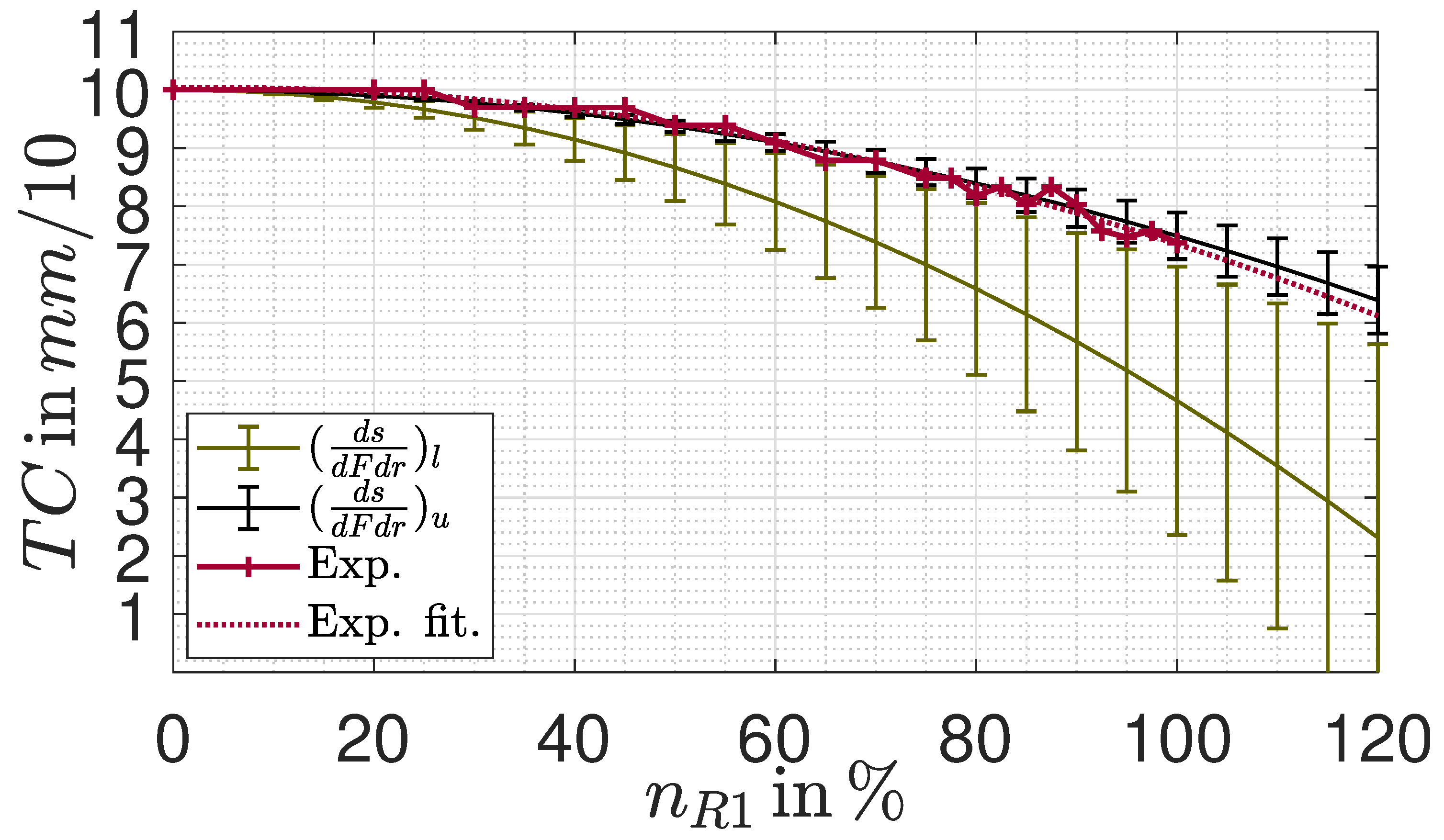
assuming that the considered is the same for all radial positions and applying equation 2 to calculate the individual elongations of each increment at radius r. The resulting tip clearances in dependency of the relative engine speed with regard to the design point speed are plotted in Figure 9, evaluated for an initial of at installation condition. The error bars are formed by the results of the lowest and highest strength blade, respectively. It can be inferred that at an elongation between and is present on average, considering the lower and upper slope.
These results pave the way for engine testing in terms of a tip clearance measurement. The utilized high-speed camera FASTCAM Mini AX200 was positioned in front of the engine. For these tests, the engine was not equipped with its standard inlet but with a similar one having a smaller axial length. This enabled to capture the tip clearance within the red square in dependency of the engine speed as shown in the upper part of Figure 9. A frame rate of , a zoom lens and an additional lighting source behind the engine facilitated analyzable shots. From the videos of the individual speeds those photos were selected where the individual blades are at the same circumferential position to ensure comparability. The actual tip clearance was determined from the calibrated length between two reference positions at the casing and at the blade’s tip, exemplary shown in the bottom part of Figure 8.
Figure 8.
Tip clearance quantification by a high-speed camera.
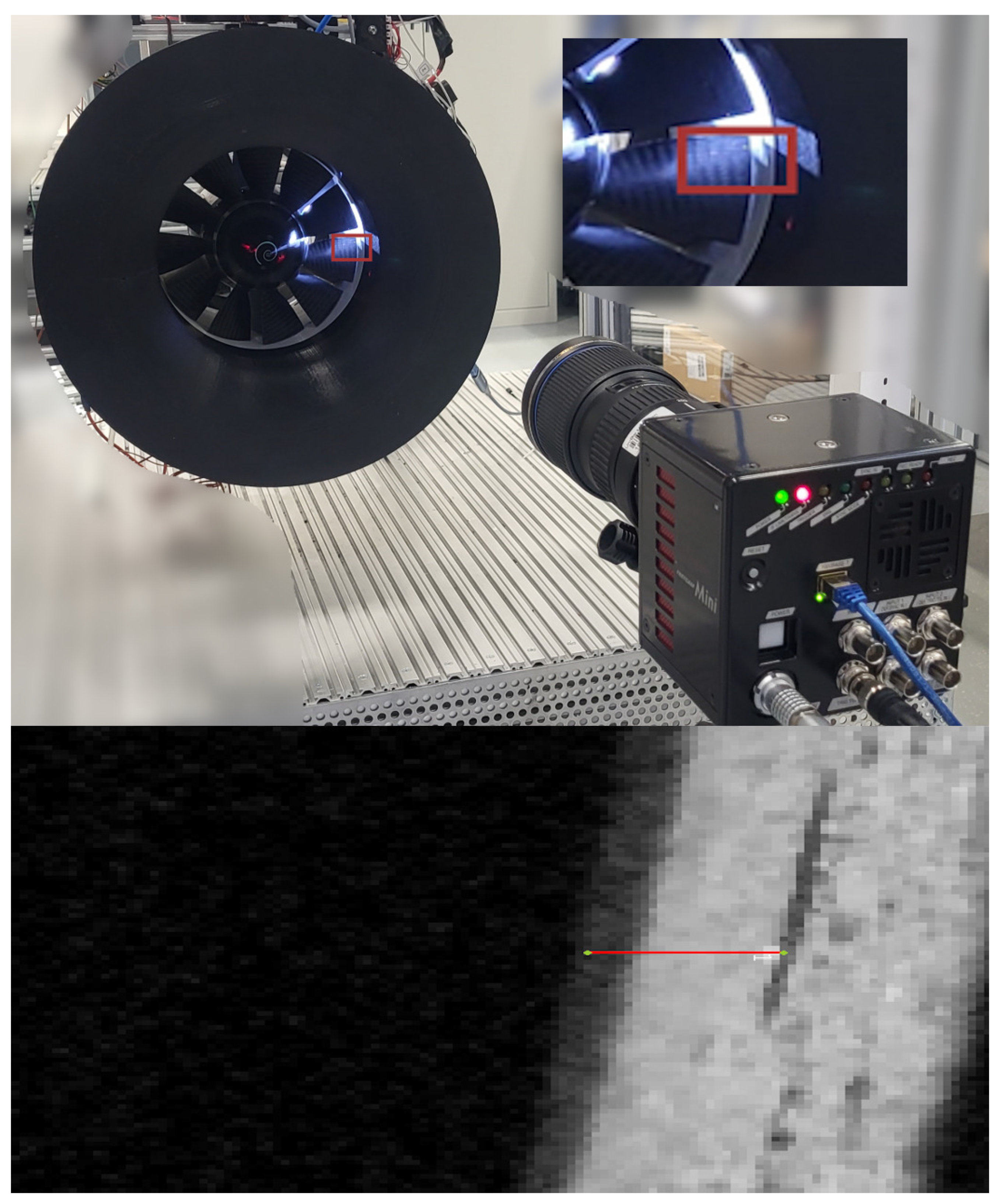
Figure 9.
Experimentally measured tip clearance in dependency of the actual engine speed n, compared to the expected results from the tensile tests based on Table 5.
Figure 9.
Experimentally measured tip clearance in dependency of the actual engine speed n, compared to the expected results from the tensile tests based on Table 5.
Besides, the captured videos were evaluated for critical flutter effects, differing elongations of the individual blades or misbalancing not detectible within the former static balancing. However, all these tests were negative.
In order to definitely avoid contact to the casing, a conservative grinding of the blades’ tips was conducted to achieve a tip clearance at installation condition of .
The actual measured tip clearance and a resulting, exponential fitted curve are included in Figure 9 as solid and dotted red line. On the one hand, there is a good agreement between the measured elongation and the calculated values based on the upper, larger gradient measured by the tensile tests though the calculations seem to underestimate the actual elongation slightly. Three possible assumptions could be considered for this deviation. First, it appears reasonable that the the density within the actual blade area is higher than that of the root due to the fleece used within it. Second, the blades are slightly thicker than initially designed as discussed previously. Both would result in higher centrifugal forces and therefore larger elongations when assuming that the deviating thickness results from additional resin which only increases mass but does not bear significant loads. In addition, the calculated slopes are averaged over both the actual blade and the transition zone. Due to the strong curvature of the transition in comparison with the plane structure of the actual blade it can be expected that their slopes vary widely. On the other hand, the resulting tip clearance at design point, approximately , is larger than the initially specified value of and further discussed below within the context of the CFD-validation.
Nevertheless, the test procedure seems to be a suitable indicator to predict the actual operational behavior. Even if the potential range of expectable tip clearances appears to be large and requires careful commissioning tests of the engine including a tip clearance measurement, the calculations could be used to determine more appropriate values for than set here. To improve the calculation accuracy further, the elongations of the different zones should be measured individually due to their substantial difference in ply structure, for instance by optical measurement systems. Besides, elongations of the inner disk were excluded and may account for deviations between tensile test and experimental results, too. Addressing the second research question raised above, it can be summarized that the design, manufacturing and commissioning of composite-blades became feasable. Key factors are the direct integration of the manufacturing procedure into the design tool itself and the utilization of innovative approaches like the printed mouldings, reducing the manufacturing effort massively. Besides, the safety factors calculated above indicate a safe operation over a wide range of engine speeds and the test procedure could be verified. However, the higher total pressure ratio of the future contra-rotating propulsor requires larger engine speeds. To account for the subsequent higher loads, the blade design, especially the layer structure, should be optimized. To improve the design procedure, the test results could be utilized to set up a detailed FEM model that takes the individual ply orientation and anisotropic material characteristics of a composite structure into account. Besides, further comparisons of different blade curings or the selection of other materials of both resin and actual fabric seem to be beneficial. However, a composite rotor could be successfully manufactured, compared to the initial rendering in Figure 10. Within the following it will now be examined whether this composite rotor does not compromises the design tool validation.
2.3. Experimental Setup
Apart from the rotor being the engine’s main component, the nozzle and the test bed are discussed briefly in the following as they are the key-elements enabling the actual design tool validation. In addition to the actual design point calculation, considered by the tool as discussed at the beginning, the operating behavior at off-design points is of particular relevance. For axial compressors and fans, the operating point of highest efficiency is typically close to the surge limit. However, typically less efficient operating points are chosen that have a larger margin to this limit [35]. As the later contra-rotating engine aims to enlarge the operating range towards more efficient operating points through targeted adjustment of operating parameters, especially the speed ratio, it is essential that not only the design point but also the off-design points are accurately represented using the CFD utilized for the design tool. Consequently, this will be revisited in the following experimental tool validation, too. Therefore, an adjustable nozzle was constructed. It has 16 segments which can be moved via a servo to adjust the nozzle’s outer geometry and the size of the nozzle’s outlet cross section . Furthermore, each of the segments is slightly curved, so that the outlet cross sectional area is always in a near circle shape, which reduces losses. Because of the relatively low static pressure and low temperature it was possible to produce most parts of the nozzle at the institute. The segments of the nozzle were -printed out of polylactide (PLA), which has reduced the costs as well as shortened the production time. To validate that the size of stayed consistent during operation and testing, pictures were taken and superimposed by a high-speed camera both in and out of operation. Since the variable nozzle’s outlet widened at higher engine speeds, fully -printed outer nozzles with different sizes that fulfill the requirement of a constant outlet cross section were printed, utilized and successfully tested instead whereas the adjustable nozzle’s design will be improved. Those differently sized nozzles were also taken over into the to simulate the engine behavior at throttled and unthrottled conditions, too.
The test bed built at the institute serves for both static engine testing and experimental measurements in a wind tunnel, particularly in conjunction with the particle image velocimetry (PIV) system. Besides, it is designed not only for the current single-engine reference propulsion system but is also preconfigured for a future, dual-engine contra-rotating configuration. Its data acquisition system, based on National Instruments (NI) soft- and hardware, includes various modules for data collection. This includes an ambient temperature measurement using PT100 sensors, a six-component strain gauge for force and momentum measurement along the engine’s axes, and a digital pressure sensing system with a focus on absolute and differential pressure measurements. Having a rated accuracy of full scale, the strain gauge can measure up to and the engine and the gauge are horizontally orientated before testing. All pressure sensors are rated with an accuracy of of their full scale, having an effective resolution of . Whereas the absolute pressure can be obtained by a 0 to absolute sensor with a resulting maximum error of , the differential sensor can measure up to , resulting in a maximum deviation of with a resolution of . The offset of all pressure sensors is regularly taken and compensated. Additionally, the absolute mechanical engine speed n is captured using a laser-based light barrier system, consisting of a hole within the spinner cone and an edge counting within a digital input module. Data are read from the NI DAQ system by a connected measurement and control PC running LabVIEW-based data acquisition and control software. All parameters are collected with an adjustable frequency; for the following were chosen as steady state operation should be measured only. Due to the static operation outside the wind tunnel for the following tool validation, the obtained static inlet conditions of temperature and pressure equal their total values and , respectively. According to the Mach number similarity, they are used to calculate the corrected engine speed as follows [35]:
These calculations are performed using a reference temperature and pressure derived from the ISA standard atmosphere[23] at an altitude of , which equals the institute’s altitude. Since those reference conditions were already set within the design tool as inputs as well as in the following CFD as boundary conditions on inlet and outlet surfaces, the mechanical design speed of equals the corrected design speed, stored within the control software. To enable operation at higher temperatures, resulting in higher mechanical speeds, a slightly oversized water cooled brushless motor was selected and installed. It is powered by a water-cooled electronic speed controller (ESC), which is, in turn, supplied by a power source capable of providing up to . To accommodate future operation with two electric motors having a combined power of up to , a second identical power supply unit is already integrated into the test bed. The ESC generates the required sinusoidal signal by selectively applying voltage to the motor’s three phases, with the duty cycle of this signal determining the time-averaged voltage. The actual motor speed then results in accordance with the motor-specific rating. However, the actual speed is governed by further factors such as motor heating or the internal resistance of cables and the motor. The ESC is controlled via a PWM signal from the DAQ system, with the duty cycle regulated by the measurement and control system to maintain a constant corrected speed set by the user.
To protect the various sensor cables from the strong magnetic field of the motor supply, shielded cables are exclusively used. Mass flow rate is calculated from the differential pressure, measured between the engine’s inlet and the ambient, and the cross sections inlet and is corrected similar to the engine speed as shown above [35]:
Additionally, the total pressure difference to ambient can be measured within the engine using a radial traversing unit, enabling the calculation of area averaged values. This unit is equipped with a calibrated, miniature five-hole probe from Vectoflow. This probe features five pressure ports in its head, allowing the determination of both total pressure and flow angles.
3. Results: Design Tool Validation
To validate the design tool, the engine’s operation was investigated both in CFD and experiment not only at design point, having a nozzle position of , but also in throttled and unthrottled conditions by adjusting the nozzle’s outlet area between and . Besides, four different corrected engine speeds of , , and were evaluated, referred to the design point speed specification initially given in Table 1. In the experiment, the traversing unit was utilized at each operation point to determine the total pressure at 30 radial positions behind the rotor with a higher resolution close to hub and shroud as shown in Figure 11, discussed in detail later. At each radial position, 50 samples were captured with , averaged and used to calculate an area-averaged total pressure increase and total pressure ratio of the position after the rotor against ambient since the conditions in front of the rotor cannot be measured.
To ensure comparability, the traversing’s axial position aligns with the CFD’s interface between the rotor and stator domains. Similar, the CFD is also evaluated at 318 uniformly distributed radial positions, each averaged over the domain circumference, and the total pressure difference and ratio between this station at the rotor’s outlet and the set pressure of the overall inlet was calculated.
To begin with the validation, the design point results are compared in Table 6, on one hand, based on the absolute values of total pressure increase , and on the other hand, using relative errors with regard to the experimental results.
In order to establish comparability here, too, the initially specified is multiplied with the final iterative design process’ value of to receive the corresponding pressure increase, given in the first line of Table 6. Although the initial specification corresponds to a mass flow-averaged value due to the implemented calculation rules and, therefore, comparability is not necessarily guaranteed, it is in good agreement with the experimentally determined value with a deviation of . The three different CFD results seem to be in contradiction to the abortion criterion of the iterative design process, requiring a deviation of less than to the initial specification as discussed above. However, during this process a mesh slightly finer but geometrically similar to the third considered mesh was steady-state simulated and evaluated mass-flow averaging over the rotor only, undercutting the abortion criterion. The CFD results deviate from each other in accordance with the discussions above, but the deviations of all of these considered simulations from both the experiment and the initial specification are small.
This seems to confirm that the second mesh was a suitable selection for simulating the engine’s performance map, plotted against the experimental results in Figure 12.
In general, the measured throttle curves of the RPS comply with the expected counterplay of mass flow and total pressure ratio. Especially the unthrottled performance at and nozzle opening is very well represented by the CFD, but also the design operating line exhibits minor deviations only from the experimental results, even apart from the previously discussed design point. Like the relative deviation of the corrected mass flow the deviation of the total pressure increase between CFD and experiment decreases from at corrected speed to at speed. Since the CFD simulations were carried out with the design point clearance of always, whereas the tip clearance decreases in real operation from at standstill to at speed in accordance with the measurement carried out above, one could expect a decreasing deviation as described. However, the chosen second mesh cannot confirm this tip clearance effect as the simulated pressure ratio at design point operation is not larger as expected with a smaller clearance but smaller. Returning to Table 6, the third mesh may be capable to map this effect, resulting in a larger total pressure increase, but such detailed investigations of flow phenomena are not required for the tool validation carried out here.
The smaller the nozzle’s cross section the higher the pressure build-up within the engine and the smaller the corrected mass flow . This directly influences the fluid’s angle of incidence i against the blades. If this angle is too high or too low a flow separation or even a stall on the fan-blades can be the result. In the ideal case without losses the resulting throttle curves would be straight lines. However, apart from the losses caused by a deviating angle of incidence, the real throttle curves are influenced by friction and tip clearance or slipping effects [35], but the surge line was not yet reached by a nozzle opening of . However, even the simulation of these throttled operation points seems to be feasible by the transient simulation approach, though the deviations increase towards more throttled operation points, reaching a maximum of at corrected speed and remaining nozzle opening. Since the design tool is intended for future use in designing a fan with a higher pressure ratio, particularly concerning the throttled condition, it seems sensible to re-examine whether the increased computing effort of a finer mesh may be justified in order to potentially achieve higher accuracy.
Apart from the actual performance chart, a radial comparison of the total pressure increase is plotted in Figure 11. For all radial positions, there is a low standard deviation in a range of 23 to , which falls within the measurement deviation of the utilized digital differential pressure sensors. The original design based on the free vortex design principle is apparent in the CFD results through the nearly constant total pressure increase over a wide range of the normalized span, approximately from to . This is also evident in the experimental data up to a radial height of . Both CFD and experimental data show a significant drop in total pressure increase in the span range close to the blade’s tip, likely attributable to clearance losses and blade tip vortex effects. Given that the probe can be precisely positioned by using a stepper motor for the drive, the simulation appears to underestimate the tip losses as the drop in total pressure increase starts at a larger radial position. Similar results were already highlighted in the previous project, as described in [22]. Additionally, it was assumed that steady-state simulations might overestimate the influence of the tip vortex or that the measurement equipment was not able to capture it due to the transient nature of this phenomenon. In contrast, there is a measurable slight increase captured by the measurements of the RPS in total pressure in a radial range of to , just below the significant drop. The transient simulation results also show a similar, but minor and radial shifted increase. Though the drop close to the tip appears to be underestimated of the transient simulation applied here, too, the difference between simulation results and experimentally recorded data is much smaller than the observed differences compared to steady-state simulation results in [22].
Overall, the chosen simulation approach seems to be suitable to map the RPS performance characteristics accurately; the deviations between CFD and experimental data are within an acceptable range in order to consider the tool to be validated. In addition to the discrepancies in tip clearance already discussed, further geometric deviations may contribute to the discrepancies between CFD and experimental results. As mentioned earlier, the actual blade is thicker and has a shorter chord length compared to its CFD counterpart due to manufacturing tolerances. Nevertheless, the found composite manufacturing process does not seem to compromise the tool validation and experimental verification of the design approach, though it has to be further discussed in the context of future, aerodynamically higher loaded blades. Other factors that could contribute might include rougher surfaces than assumed in the CFD, the application of mixing plane or transient rotor-stator approaches, or the modeling of only one and two blade passages, respectively.
4. Discussion and Conclusion
Returning to the initial research questions, a design and manufacturing process for carbon composite blades feasible for the use within the university’s context and not compromising the tool validation was developed, enabling future transferable research. This was facilitated by the two key factors utilization of printed mouldings and a ply creation directly integrated into the design tool. Further improvements regarding the geometric tolerances can be expected from the application of a newer, state-of-the-art resin. The tensile tests carried out were evaluated regarding the blade load assumptions, based on the tip clearance measured during operation. The data of these tensile tests should be used to validate a detailed FEM model. To utilize the composite blades for the future, contra-rotating propulsor and its mechanically higher blade loads, this model should be used to optimize the ply structure.
The tool’s iterative character including CFD simulations, as anticipated, improves the accuracy massively compared to an empirical formulation-based tool. The deviations between the initial specification and both the CFD and experimental data were reduced to a small percentage range, even though the manufactured composite blades deviate slightly from the initial design.
The application of transient CFD simulations improves the simulation accuracy for off-design operation points, especially in throttled operation. Since the computational effort is similar to the previously used steady state simulations, this simulation type is utilized for prospective applications of the iterative design tool. However, the application of a finer mesh may be reasonable in spite of the higher computing effort. Particularly for the future contra-rotating engine, it seems sensible to set the iteratively found deviation angles at more than three radial positions. This will minimize the deviations between the specified and actual inflow into the second rotor over a wider range of the span. Further discussions of flow phenomena appears to be useful to improve simulation accuracy, for instance by the utilization of the institute’s particle image velocimetry system. Since the tip clearance seems to have a large impact on the engine’s performance, it should be considered in dependency of the engine speed during simulation by incorporating the already mentioned detailed FEM analysis. Within the context of future research at this now available propulsor the differences between simulations and experimental results at operation points with a large tip clearance aim for an active tip clearance control which may improve the propulsor’s performance. Both the design tool and the manufacturing process of composite blades will now be utilized to extend the operation range of electric aircraft engines by designing freely scalable contra-rotating, ducted engines.
Author Contributions
Conceptualization, S.H. and A.H.; methodology, S.H., A.H. and L.R.; software, S.H., L.R. and H.B.; validation, S.H.; formal analysis, S.H.; investigation, S.H. and A.H.; resources, S.H. and H.B.; data curation, S.H. and L.R.; writing—original draft preparation, S.H., L.R. and H.B.; writing—review and editing, S.H. and A.H.; visualization, S.H. and L.R.; supervision, A.H.; project administration, A.H. and S.H.; funding acquisition, A.H. All authors have read and agreed to the published version of the manuscript.
Funding
This publication is funded by the project Electric Aircraft Propulsion - safe, efficient, digitally linked (ELAPSED) within the cluster dtec.bw – digitalization and technology research center of the federal armed forces of Germany which we gratefully acknowledge. The cluster dtec.bw is funded by the European Union - NextGenerationEU.
Conflicts of Interest
The authors declare no conflicts of interest.
Abbreviations
The following abbreviations are used in this manuscript:
| 0 | ambient conditions |
| 1.1 | inflow rotor |
| AS | axial spacing |
| F | force |
| fused deposition modeling | |
| IPS | innovative propulsion system |
| K | construction angle |
| Mach number | |
| ML | mean line |
| P | power |
| R | rotor |
| RPS | reference propulsion system |
| S | safety factor |
| stereolithography | |
| TC | tip clearance |
| cor. | corrected |
| d | profile thickness |
| h | Altitude |
| i | number of blades |
| i | incidence angle |
| is | isentropic |
| m | mass |
| n | rot. speed |
| p | pressure |
| p | percentage deviation |
| r | radius |
| s | chord length |
| t | split |
| t | total |
| rel. flow angle | |
| deviation angle | |
| efficiency | |
| total pressure ratio |
References
- International Energy Agency. Global Energy Review 2020. https://www.iea.org/reports/global-energy-review-2020, 2020. Accessed 20th of September 2023.
- Royal Netherlands Aerospace Centre (NLR) and SEO Amsterdam Economics. Destination 2050: a route to net zero european aviation. https://www.destination2050.eu/, 2021. Accessed 18th of September 2023.
- Adu-Gyamfi, B.A.; Good, C. Electric aviation: A review of concepts and enabling technologies. Transportation Engineering 2022, 9. [Google Scholar] [CrossRef]
- Gray, N.; McDonagh, S.; O’Shea, R.; Smyth, B.; Murphy, J.D. Decarbonising ships, planes and trucks: An analysis of suitable low-carbon fuels for the maritime, aviation and haulage sectors. Advances in Applied Energy 2021, 1, 100008. [Google Scholar] [CrossRef]
- Klöwer, M.; Allen, M.; Lee, D.; Proud, S.; Gallagher, L.; Skowron, A. Quantifying aviation’s contribution to global warming. Environmental Research Letters 2021, 16, 104027. [Google Scholar] [CrossRef]
- Sacchi, R.; Becattini, V.; Gabrielli, P.; Cox, B.; Dirnaichner, A.; Bauer, C.; Mazzotti, M. How to make climate-neutral aviation fly. Nature Communications 2023, 14. [Google Scholar] [CrossRef]
- Kharina, A.; Rutherford, D.; Zeinali, M. Cost assessment of near and mid-term technologies to improve new aircraft fuel efficiency. https://api.semanticscholar.org/CorpusID:113796297, 2016. International Council on Clean Transportation.
- European Commission, Directorate-General for Mobility and Transport, Directorate-General for Research and Innovation. Flightpath 2050: Europe’s vision for aviation – Maintaining global leadership and serving society’s needs; Publications Office, 2011. [CrossRef]
- Publications Office of the European Union. Communication from the commission to the European parliament, the European council, the council, the European economic and social committee and the committee of the regions. https://eur-lex.europa.eu/legal-content/EN/TXT/?qid=1576150542719&uri=COM%3A2019%3A640%3AFIN, 2019.
- ZeroAvia Inc.. Truly Clean Aviation. https://zeroavia.com/. Accessed 10th of September 2023.
- H2FLY GmbH. H2Fly breaking the hydrogen barrier. https://www.h2fly.de/. Accessed 10th of September 2023.
- Universitaet der Bundeswehr Muenchen. Forschungsprojekt ELAPSED. https://www.unibw.de/elapsed. Accessed 10th of September 2023.
- Rossow, C.; Wolf, K.; Horst, P. Handbuch der Luftfahrzeugtechnik; Hanser Fachbuchverlag, 2014.
- Hawner, S.; Hupfer, A. Entwicklung eines CFD-Auslegungstools fuer ein gegenlaeufiges, elektrisches Fantriebwerks und Anwendung fuer eine Parameterstudie im Designpunkt. DLRK 2022 2022. [CrossRef]
- Carter, A.; Hughes, H. A theoretical investigation into the effect of profile shape on the performance of airfoils in cascada; Aeronautical Research Council (ARC), Report No. 2384, Ministry of Supply, National Gas Turbine Establishment, 1946.
- Carter, A. The Low Speed Performance of Related Aerofoils in Cascade; Aeronautical Research Council (ARC), Ministry of Supply, National Gas Turbine Establishment, 1950.
- Qiu, X.; Japikse, D.; Zhao, J.; Anderson, M.R. Analysis and Validation of a Unified Slip Factor Model for Impellers at Design and Off-Design Conditions. Journal of Turbomachinery 2011, 133, 041018. [Google Scholar] [CrossRef]
- Schnös, M. Eine Auslegungsmethodik für mehrstufige Axialverdichter auf Basis einer Profildatenbank. https://elib.dlr.de/140758/, 2020. Ruhr-Universität Bochum.
- S. Lieblein. Incidence and deviation angle correlations for comressor cascades; ASME journal of basic engineering, 82, pp. 575-587, 1960.
- Ebus, T.; Dietz, M.; Hupfer, A. Expermimental and numerical studies on small contra-rotating electrical ducted fan engines. CEAS Aeronaut 2021, 12, 559–571. [Google Scholar] [CrossRef]
- Ebus, T.; Dietz, M. Small electrically powered contra-rotating turbo fan engines for high-speed aircraft application. AIAA Scitech 2020 Forum 2020. [Google Scholar] [CrossRef]
- Ebus, T.; Dietz, M.; Hupfer, A. Detailed Performance Studies on a Small Electric-Powered Contra-Rotating Ducted Fan Engine. Journal of Propulsion and Power 0, 0, 1–12. [CrossRef]
- International Civil Aviation Organization. Manual of the ICAO standard atmosphere, extended to 80 kilometres (262 500 feet), 3 ed.; ICAO, 1993.
- Scholz, N. Aerodynamik der Schaufelgitter, 1 ed.; Verlag G. Braun, 1965.
- C. Mistry, A.P. Effect of variation in axial spacing and rotor speed combinations on the performance of a high aspect ratio contra-rotating axial fan stage. Journal of Power and Energy 2012.
- Y. Lei Y. Ji, C.W. Optimization of aerodynamic performance for co-axial rotors with different rotor spacings. International Jurnal of Micro Air Vehicles 2018.
- Nayak, N.; Mistry, C. Criteria for selection of solidity in design of contra rotating fan stage. NAPC 2017 2017.
- Verein Deutscher Ingenieure. Durchflussmessung mit Drosselgeräten. Blenden und Düsen für besondere Anwendungen. Beuth-Verlag GmbH, Berlin 1991.
- Celik., I.; Ghia, U.; Roache, P.; Freitas, C.; Coleman, H.; Raad, P. Procedure for estimation and reporting of uncertainty due to discretization in CFD applications. Journal of Fluids Engineering 2008, 130, 078001. [CrossRef]
- Abumeri, G.; Kuguoglu, L.; Chamis, C. Composite fan blade design for advanced engine concepts. https://ntrs.nasa.gov/api/citations/20040040080/downloads/20040040080.pdf, 2004. NASA Technical Reports.
- Coroneos, R.M.; Gorla, R.S.R. Structural analysis and optimization of a composite fan blade for future aircraft engine. Int. J. Turbo Jet-Engines 2012, 29, 131–164. [Google Scholar] [CrossRef]
- DLR Institut für Antriebstechnik. CRISP II: Counter rotating integrated shrouded propfan II. https://www.dlr.de/at/desktopdefault.aspx/tabid-7162/11868_read-27991/. Accessed 10th of September 2023.
- Schmid, T.; Lengyel, T.; Schmidt, T.; Nicke, E. Optimization of a carbon-fiber composite blade of a counter-rotating fan for aircraft engines. 13th European Conference on Turbomachinery Fluid Dynamics & Thermodynamics 2019. [CrossRef]
- DIN e.V. (Hrsg.). Kunststoffe - Bestimmung der Zugeigenschaften - Teil 5: Prüfbedingungen für unidirektional faserverstärkte Kunststoffverbundwerkstoffe (ISO 527-5: 2021). Beuth-Verlag 2022.
- Rick, H. Gasturbinen und Flugantriebe: Grundlagen, Betriebsverhalten und Simulation; VDI-Buch, Springer Berlin Heidelberg, 2013.
Figure 1.
Toolchain of the developed engine design tool, adapted from the initial introduction in [14].
Figure 1.
Toolchain of the developed engine design tool, adapted from the initial introduction in [14].
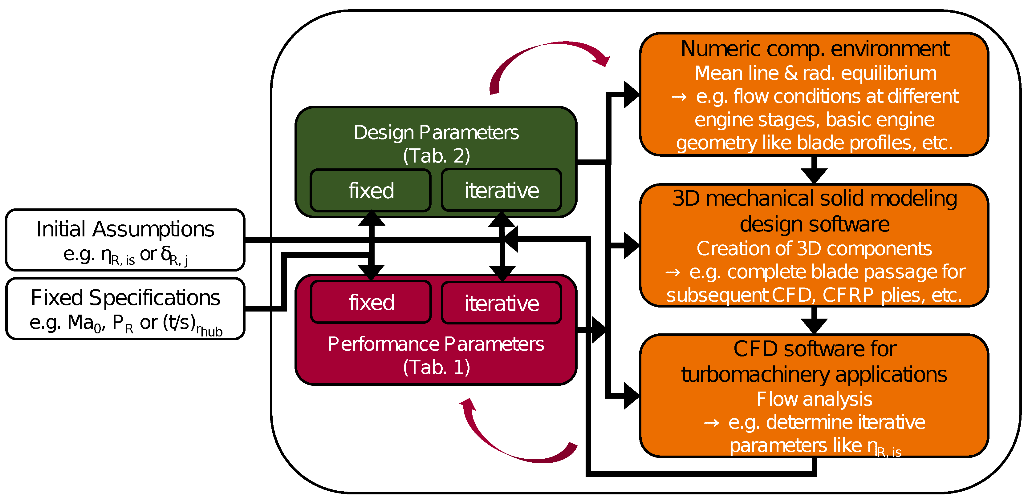
Figure 2.
Adjustment of the local deviation angle and resulting deviation of the global performance parameters p (lower part) in dependency of the actual iteration.
Figure 2.
Adjustment of the local deviation angle and resulting deviation of the global performance parameters p (lower part) in dependency of the actual iteration.
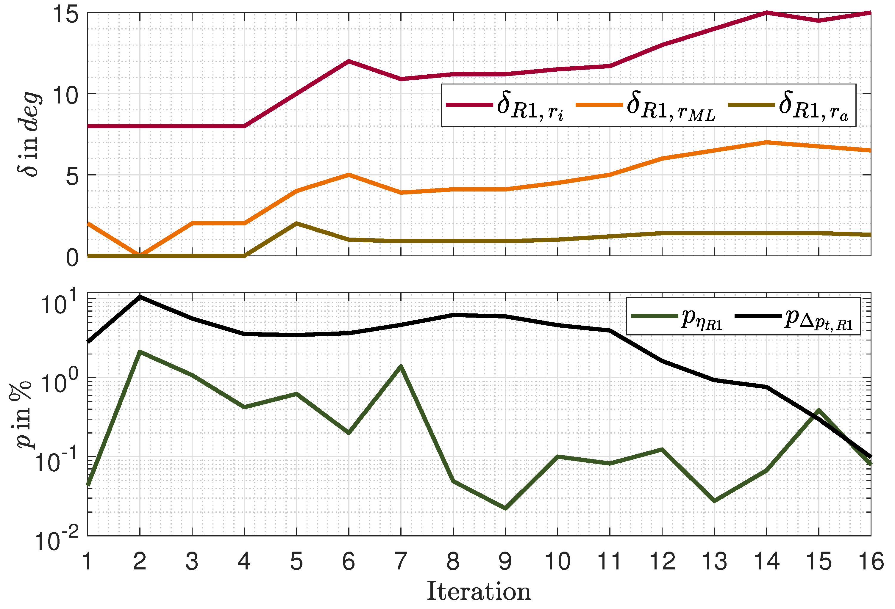
Figure 3.
CAD rendering of the RPS in its final geometry of the iteration.

Figure 4.
View of the blade tip’s cross sectional 3D point cluster (left), including those of two inner plies and the upper part of the outermost pressure and suction side plies (indicated in blue), shown also as 3D geometry and 2D unwrap (center, right).
Figure 4.
View of the blade tip’s cross sectional 3D point cluster (left), including those of two inner plies and the upper part of the outermost pressure and suction side plies (indicated in blue), shown also as 3D geometry and 2D unwrap (center, right).
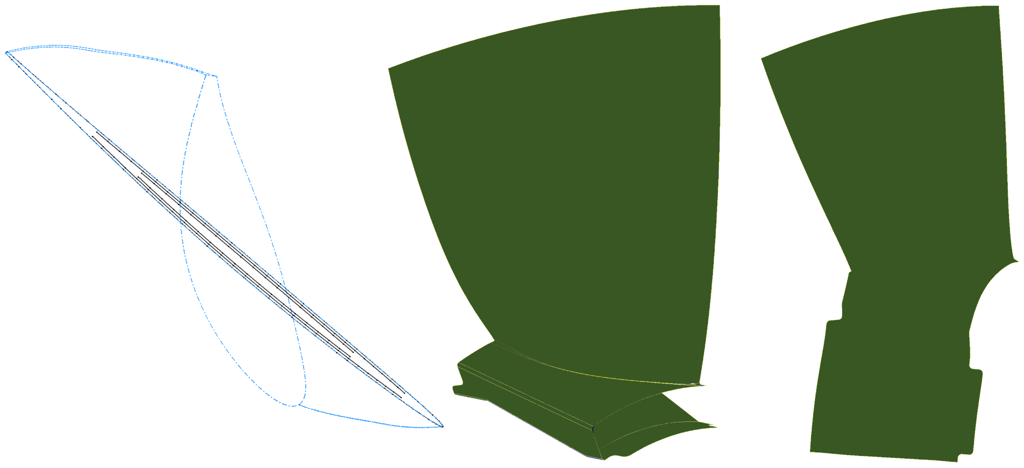
Figure 5.
Initial (left) and final (right) version of the composite blade.
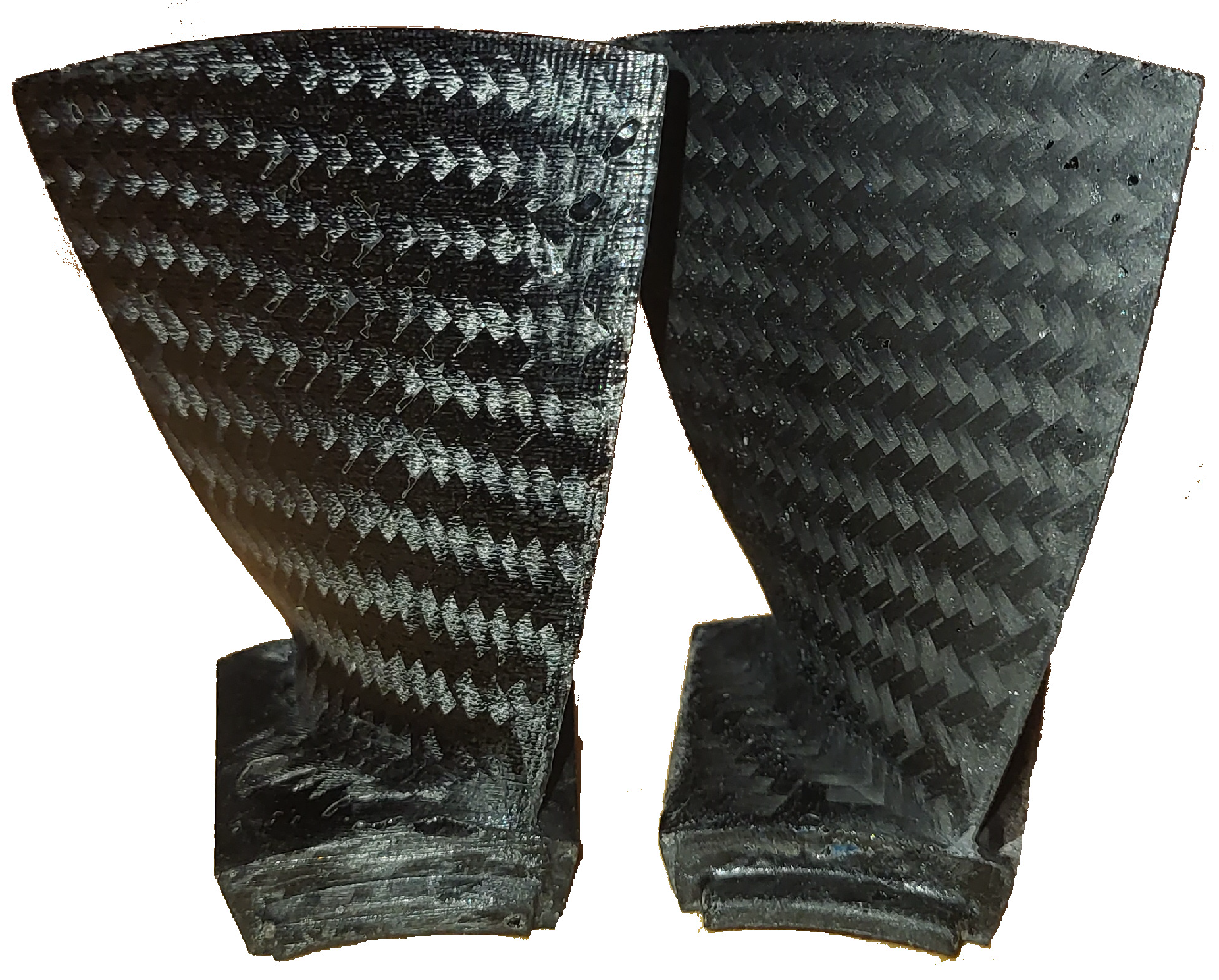
Figure 6.
Elongation of the seven blades that received the same curing conditions in dependency of the applied load.
Figure 6.
Elongation of the seven blades that received the same curing conditions in dependency of the applied load.
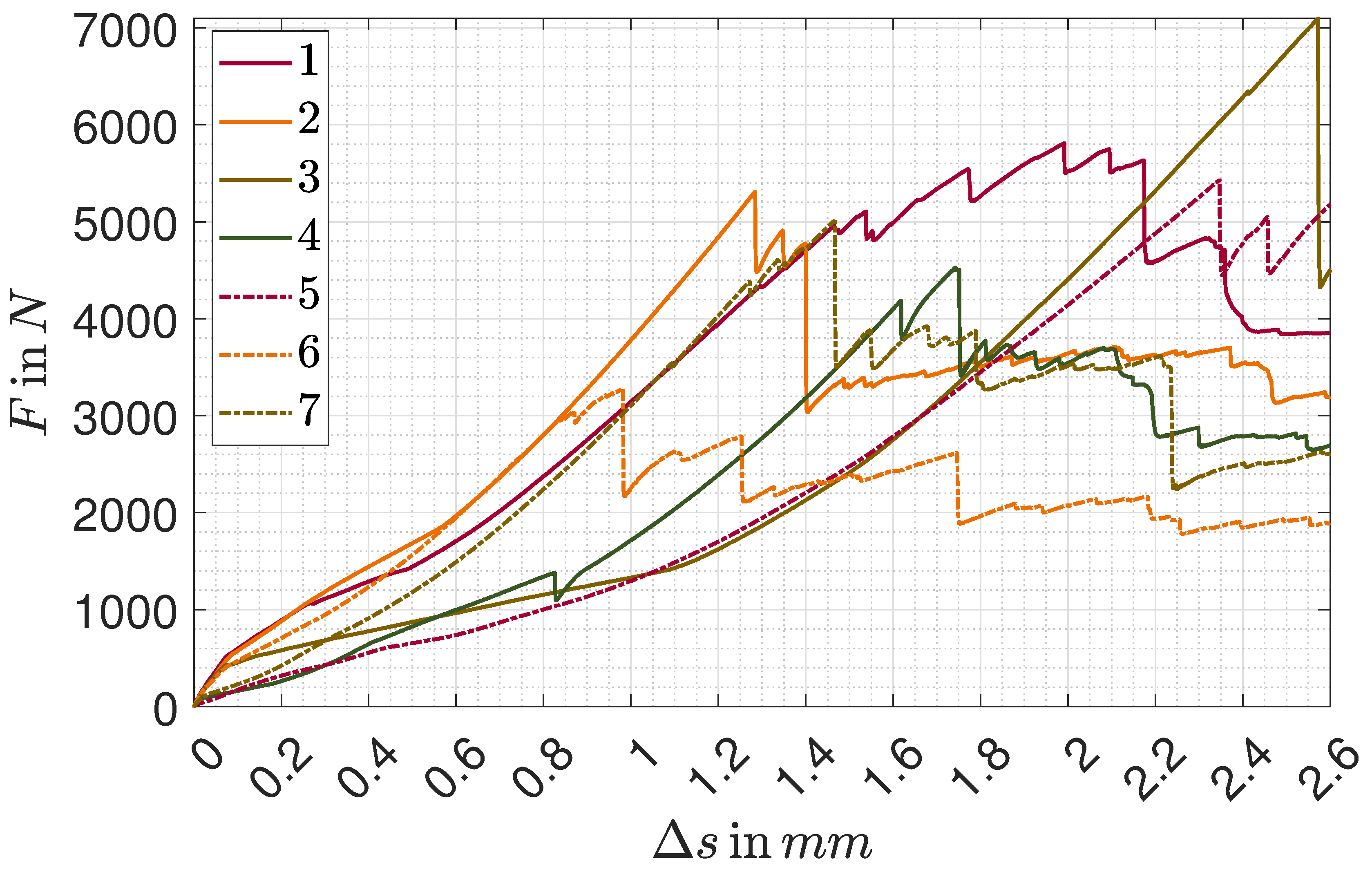
Figure 7.
Typical damage pattern delamination within the red circle at the blade’s backside transition from the root into the actual blade.
Figure 7.
Typical damage pattern delamination within the red circle at the blade’s backside transition from the root into the actual blade.
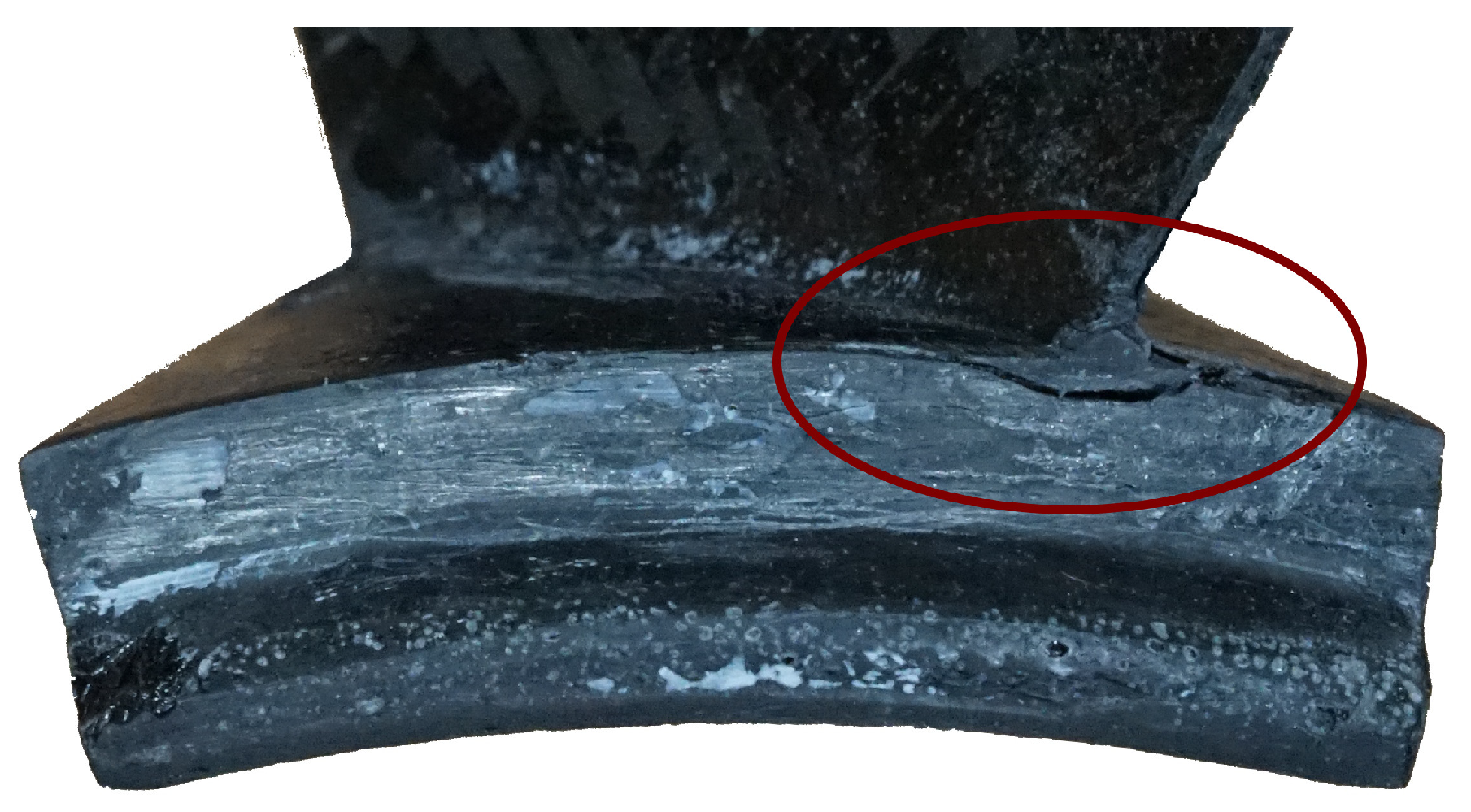
Figure 10.
Comparison of the rotor design (CAD rendering, left) and the manufactured composite rotor (right) of the reference engine.
Figure 10.
Comparison of the rotor design (CAD rendering, left) and the manufactured composite rotor (right) of the reference engine.
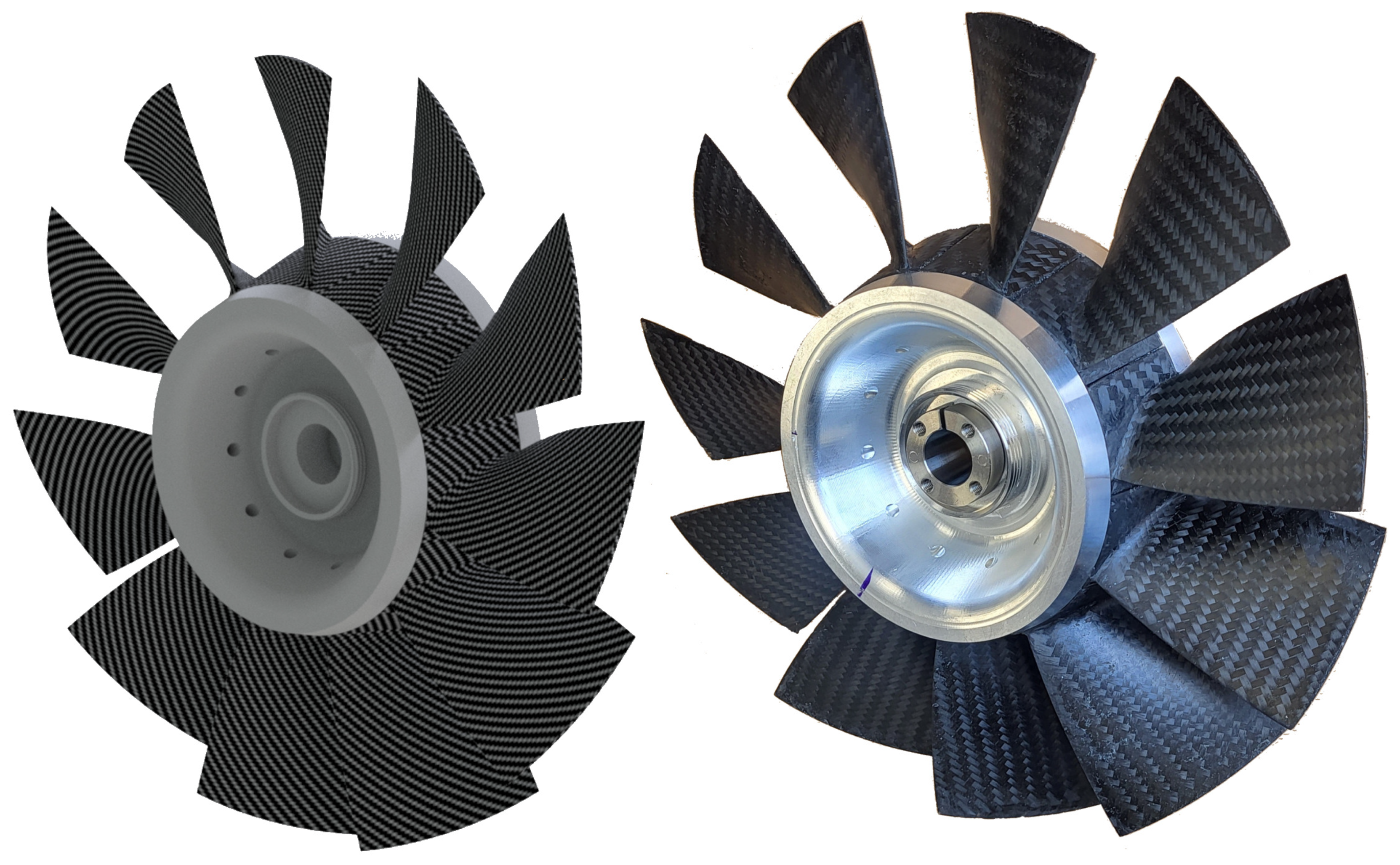
Figure 11.
Total pressure increase from ambient to the measurement position in dependency of the normalized span. Nozzle opening equals design point cross section. Comparison of CFD and experimental results at different corrected speeds, referred to design point speed, and including standard deviations.
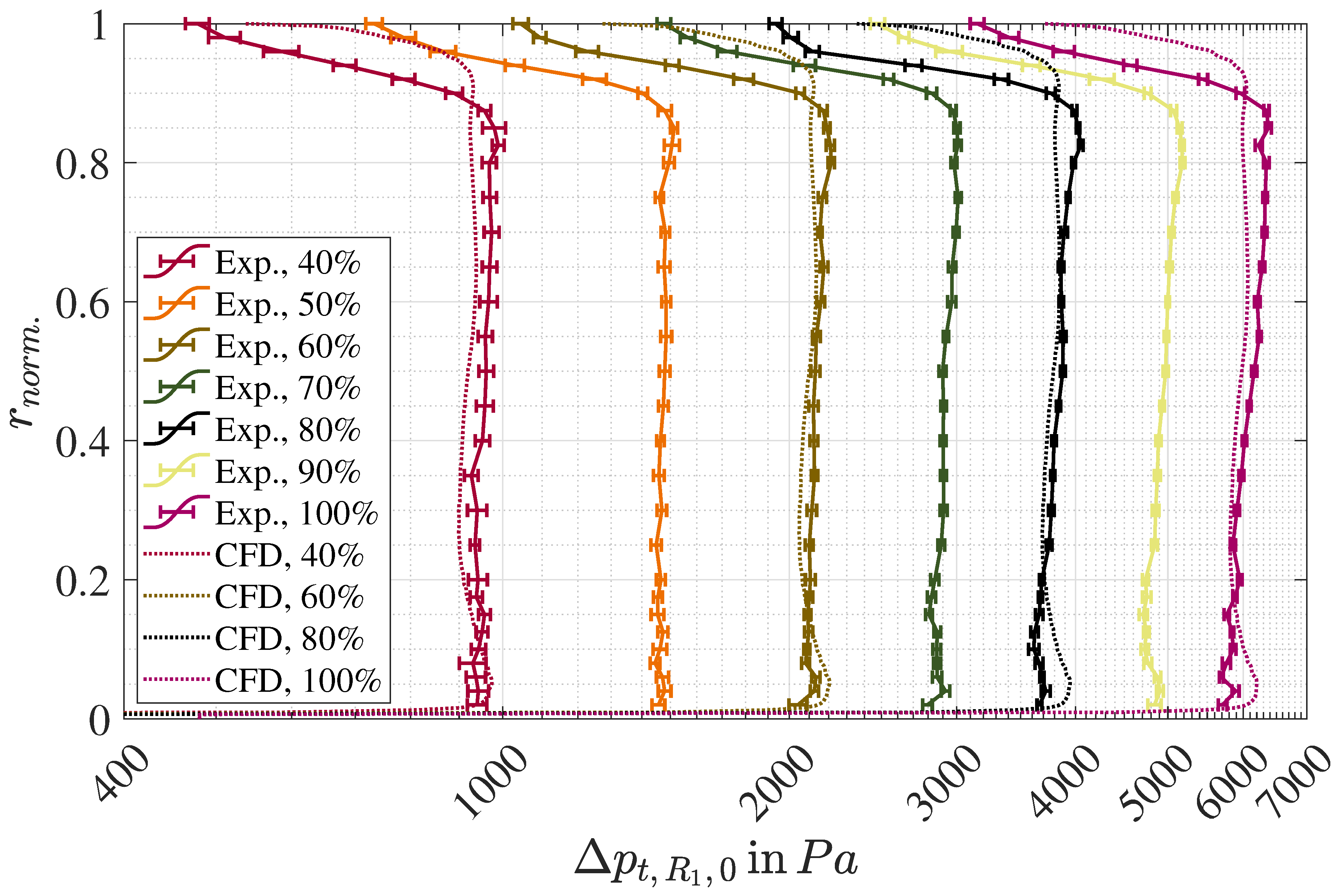
Figure 12.
RPS performance map, including CFD and experimental results of total pressure ratio and corrected mass flow at different corrected engine speeds, given within the map, and six different nozzle openings from to , given within the legend.
Figure 12.
RPS performance map, including CFD and experimental results of total pressure ratio and corrected mass flow at different corrected engine speeds, given within the map, and six different nozzle openings from to , given within the legend.
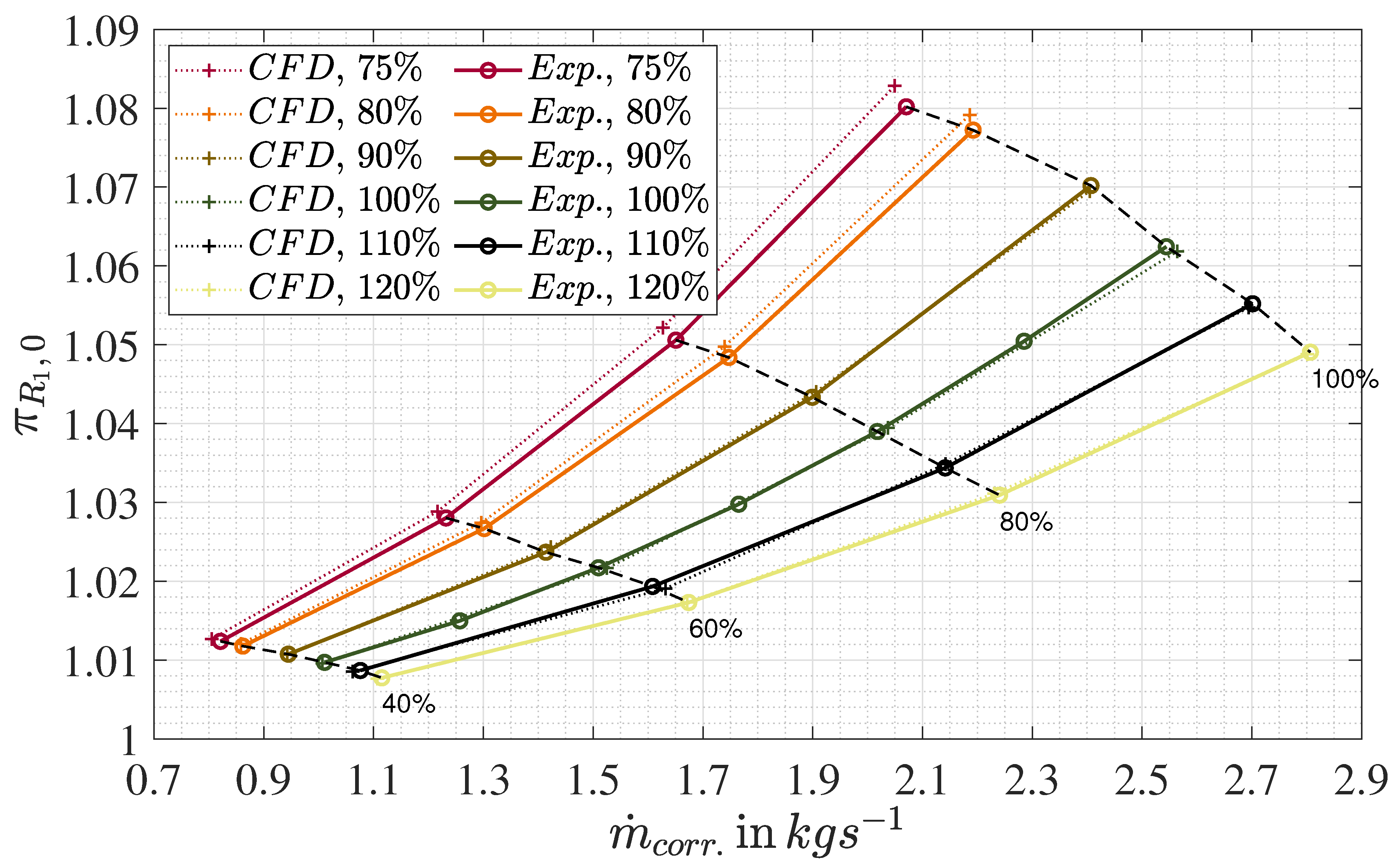

Table 1.
Extraction of the fixed and iterative performance parameters of the reference propulsion system, sorted in the order of their utilization.
Table 1.
Extraction of the fixed and iterative performance parameters of the reference propulsion system, sorted in the order of their utilization.
| Parameter | (Final) value | Unity | Category |
|---|---|---|---|
| 0 | − | fixed | |
| − | fixed | ||
| − | iterative | ||
| − | iterative | ||
| − | iterative | ||
| − | iterative | ||
| 14093 | W | fixed | |
| 14487 | fixed | ||
| − | fixed |
Table 2.
Extraction of the fixed and iterative design parameters of the reference propulsion system.
Table 2.
Extraction of the fixed and iterative design parameters of the reference propulsion system.
| Parameter | (Final) Value | Unity | Category |
|---|---|---|---|
| − | fixed | ||
| − | fixed | ||
| − | fixed | ||
| − | fixed | ||
| − | fixed | ||
| 11 | − | fixed | |
| 6 | − | fixed | |
| 15 | fixed | ||
| fixed | |||
| 15 | iterative | ||
| iterative | |||
| iterative |
Table 3.
Comparison of the simulation results in terms of relative and extrapolated relative errors for three different meshes.
Table 3.
Comparison of the simulation results in terms of relative and extrapolated relative errors for three different meshes.
| Parameter | Mesh 1 | Mesh 2 | Mesh 3 |
|---|---|---|---|
| Element No. | |||
| h | |||
| − | |||
| − | |||
| − | |||
| − | |||
| − | |||
| − |
Table 4.
Comparison of the simulation results in terms of relative errors for three different considered cases, differing by the number of time steps per period.
Table 4.
Comparison of the simulation results in terms of relative errors for three different considered cases, differing by the number of time steps per period.
| Parameter | Case 1 | Case 2 | Case 3 |
|---|---|---|---|
| Time Steps p. Period | 1 | 5 | 10 |
| − | |||
| − | |||
| − | |||
| − | |||
| − | |||
| − |
Table 5.
Safety factors S and calculated averaged slopes in dependency of the considered blades.
| Parameter | Lowest strength blade | Average | Highest strength blade |
|---|---|---|---|
| S | |||
Table 6.
Comparison of total pressure ratio and total pressure increase, including the initial specification and the CFD and experimental results.
Table 6.
Comparison of total pressure ratio and total pressure increase, including the initial specification and the CFD and experimental results.
| Case | ||
|---|---|---|
| Initial sp. | ||
| CFD Mesh 3, st.st. | ||
| CFD Mesh 2, st.st. | ||
| CFD Mesh 2. tr. | ||
| Exp. | − |
Disclaimer/Publisher’s Note: The statements, opinions and data contained in all publications are solely those of the individual author(s) and contributor(s) and not of MDPI and/or the editor(s). MDPI and/or the editor(s) disclaim responsibility for any injury to people or property resulting from any ideas, methods, instructions or products referred to in the content. |
© 2024 by the authors. Licensee MDPI, Basel, Switzerland. This article is an open access article distributed under the terms and conditions of the Creative Commons Attribution (CC BY) license (http://creativecommons.org/licenses/by/4.0/).
Copyright: This open access article is published under a Creative Commons CC BY 4.0 license, which permit the free download, distribution, and reuse, provided that the author and preprint are cited in any reuse.


