Submitted:
01 May 2024
Posted:
01 May 2024
You are already at the latest version
Abstract
Driven by mounting environmental apprehensions stemming from the over dependence on fossil fuels in energy and transportation sectors, extensive exploration into alternative energy sources, particularly biomass, has stimulated profound research on harnessing the potential of computational and mathematical techniques. This comprehensive survey delves into optimal models and strategies, unveiling their pivotal role in the design of biomass gasification processes.of hydrogen through biomass gasification. In this study, we aim to provide a comprehensive overview of the computational and mathematical techniques employed in optimizing biomass gasification processes, with a specific focus on enhancing hydrogen yield. Through an extensive literature review, various models and strategies will be examined, including thermodynamic analysis, kinetic modeling, reactor design, and process optimization. By uncovering the power of these techniques, we aim to contribute to the advancement of sustainable and efficient biomass utilization for the hydrogen-based future economy.This paper aims to provide an updated and comprehensive coverage of the investigations conducted on the potential of producing hydrogen from biomass through gasification. To achieve this, we incorporate the latest works that have utilized numerical modeling, simulation, optimization techniques, process heat integration, and co-generation in their studies. By encompassing these aspects, we aim to offer a broader and more in-depth re-appraisal of the subject matter. This will ensure that readers gain a holistic understanding of the advances made in the field and the potential for sustainable hydrogen production of biomass gasification.Through a meticulous re-appraisal and analysis of each subject, we can identify their respective strengths and areas that require further research effort. By thoroughly examining numerical modeling, simulation, optimization techniques, process heat integration, and co-generation, we can assess their effectiveness and applicability in the context of biomass gasification for hydrogen production. This analysis shed light on the areas where these techniques excel, as well as pinpoint limitations or gaps in current understanding. By identifying these areas, we can highlight the need for further research and development, enabling us to make significant advancements in biomass gasification processes and pave the way for a sustainable and efficient hydrogen-based future economy..
Keywords:
Biomass
; Gasification
; Hydrogen
; model
; Co-generation
; Heat
; Computational
1. Introduction
In today's ever-evolving world, the utilization of biomass as a renewable energy source is becoming increasingly crucial in our efforts to combat climate change and reduce our dependency on fossil fuels. Biomass gasification, a thermochemical process that converts biomass into synthesis gas, holds immense potential as a sustainable energy solution. However, optimizing the design and operation of biomass gasification processes is a complex and challenging task that requires advanced computational and mathematical techniques..By harnessing the power of computational tools and mathematical optimization techniques, researchers and engineers can develop innovative solutions to address the inherent complexities of biomass gasification. Through the integration of advanced modeling, simulation, and optimization methods, this research aims to shed light on the most effective approaches for designing and operating biomass gasification systems.Biomass gasification is a promising technology that plays a crucial role in the transition towards sustainable energy solutions. As the world seeks alternatives to fossil fuels, the efficient conversion of biomass into valuable synthesis gas through gasification processes has garnered significant attention. The optimization of these processes is essential to maximize energy efficiency, minimize environmental impacts, and enhance economic viability. This research aims to explore the power of computational and mathematical techniques in designing and optimizing biomass gasification processes.,The utilization of biomass as a renewable energy source is gaining momentum worldwide. With a focus on reducing greenhouse gas emissions and achieving energy security, biomass gasification presents a viable pathway towards a cleaner energy future. Drawing from a diverse array of research studies, including those by Demirbas (2004), Ramanan et al. (2007), and Srinivas and Reddy (2012), it is evident that biomass gasification offers a versatile platform for decentralized power generation and bioenergy production. By leveraging advanced modeling approaches, as discussed by Ometto and König (2017) and Wang et al. (2007), the optimization of biomass gasification processes can lead to improved performance and cost-effectiveness. Moreover, studies by Tabatabaei and Kianmehr (2015) and Uslu and Faaij (2010) emphasize the importance of comprehensive thermo-mechanical analysis and policy considerations in promoting the growth of biomass-based energy systems. The integration of computational tools, as highlighted by Xue et al. (2012) and Abada and Avila (2016), presents opportunities for optimizing biofuels supply chains and enhancing the techno-economic feasibility of biomass gasification-based power plants.By synthesizing insights from these diverse sources, this research seeks to delve deeper into the intricate realm of biomass gasification, shedding light on optimal models and strategies that can propel the sustainable development of this transformative technology.
The Research Findings Discussed In This Paper Align With Several United Nations Sustainable Development Goals (SDGs)
- ➢
- SDG 7: Affordable and Clean Energy: The focus on biomass gasification for hydrogen production contributes to the goal of ensuring access to affordable, reliable, sustainable, and modern energy sources. By exploring efficient and sustainable ways of producing hydrogen, we contribute to the transition towards clean energy systems.
- ➢
- SDG 9: Industry, Innovation, and Infrastructure: The utilization of computational and mathematical techniques, along with optimization strategies, demonstrates advancements in industry and innovation. These techniques can enhance the design and operation of biomass gasification processes, leading to more efficient and sustainable infrastructure for hydrogen production.
- ➢
- SDG 13: Climate Action: By reducing the dependence on fossil fuels and exploring alternative energy sources, such as biomass for hydrogen production, we contribute to mitigating climate change. Biomass gasification can significantly reduce greenhouse gas emissions and promote a low-carbon economy.
- ➢
- SDG 12: Responsible Consumption and Production: The research findings provide insights into optimizing biomass utilization, leading to more responsible and sustainable production practices. By maximizing the yield of hydrogen and utilizing co-generation approaches, we promote efficient resource utilization and minimize waste generation.
- ➢
- SDG 17:partnerships for the Goals: Collaboration between academia, industry, and policymakers is crucial for the successful implementation of sustainable energy solutions. The research findings can foster partnerships and knowledge-sharing among stakeholders, contributing to the achievement of the SDGs. Overall, the research findings discussed in this paper contribute to multiple SDGs, promoting sustainable energy, innovation, climate action, responsible production, and partnerships for sustainable development.
SIGNIFICANCE OF THE RESEARCH STUDY.
Advancing Renewable Energy Technologies: Biomass gasification for hydrogen production offers a renewable energy solution that can replace or reduce the reliance on fossil fuels. The research findings the significance of the research findings discussed in this paper can be highlighted in several ways.contribute to the development and optimization of biomass gasification processes, enabling the efficient and sustainable generation of hydrogen as an alternative energy carrier.
Environmental Impact Reduction: By exploring biomass gasification, the research findings contribute to the reduction of greenhouse gas emissions and other environmental impacts associated with conventional energy sources. This aligns with global efforts to mitigate climate change and promote sustainable development.
Energy Security and Independence: The research findings provide insights into the design and optimization of biomass gasification processes, enabling the production of hydrogen, a versatile and clean energy carrier. This can contribute to enhancing energy security and reducing dependency on fossil fuel imports, promoting self-sufficiency and resilience in energy systems.
Economic Opportunities: The research findings highlight the potential for co-generation and the production of valuable byproducts alongside hydrogen in biomass gasification processes. This can create economic opportunities through the utilization of waste heat and the generation of additional revenue streams, contributing to sustainable economic growth and job creation.
Knowledge Advancement: The research findings contribute to the expansion of knowledge in the field of biomass gasification and hydrogen production. By uncovering the efficacy of computational and mathematical techniques, the research findings provide a deeper understanding of the optimal models, strategies, and factors influencing the efficiency and performance of biomass gasification processes. In summary, the significance of these research findings lies in their potential to advance renewable energy technologies, reduce environmental impacts, enhance energy security, create economic opportunities, and contribute to the expansion of knowledge in the field. These findings are crucial for achieving sustainable Development goals and addressing the challenges of a rapidly evolving energy landscape.
2. Methodology
2.1. Biomass Conversion into Hydrogens
Biomass conversion into hydrogen offers a promising pathway towards sustainable energy production and decarbonization. Hydrogen, as a clean and versatile energy carrier, holds great potential for addressing the challenges of climate change and reducing dependence on fossil fuels. The process of biomass conversion into hydrogen involves various thermochemical and biochemical methods, each offering unique advantages and challenges. One of the key thermochemical pathways for biomass-to-hydrogen conversion is gasification. Biomass gasification involves the partial oxidation of biomass feedstock to produce a synthesis gas (syngas) rich in hydrogen, carbon monoxide, and other gases. The syngas can then be further processed through processes such as water-gas shift reaction or preferential oxidation to enhance the hydrogen content. Gasification offers high efficiency in hydrogen production and can utilize a wide range of biomass feedstocks, making it a versatile technology for sustainable hydrogen generation. Another thermochemical route for biomass conversion into hydrogen is pyrolysis. Pyrolysis involves the thermal decomposition of biomass in the absence of oxygen to produce bio-oil, biochar, and syngas. The syngas fraction can be further purified to increase the hydrogen content through processes like steam reforming or catalytic conversion. Pyrolysis offers the advantage of producing a liquid bio-oil that can be used as a valuable byproduct, making it a potentially economically viable route for biomass-to-hydrogen conversion. On the biochemical side, biological processes such as dark fermentation and microbial electrolysis can be employed for biomass conversion into hydrogen. Dark fermentation involves the anaerobic breakdown of organic matter by bacteria to produce hydrogen and organic acids. Microbial electrolysis utilizes electrochemical reactions by microbial communities to generate hydrogen from organic substrates. These biological processes offer the advantage of operating at mild conditions and utilizing certain types of biomass waste streams efficiently. In the context of biomass conversion into hydrogen, the selection of the appropriate conversion technology depends on factors such as feedstock availability, process efficiency, environmental impact, and economic viability. Integrating advanced computational and mathematical techniques, as highlighted in previous studies on biomass gasification, can aid in optimizing biomass-to-hydrogen conversion processes. Additionally, factors such as policy support, technological innovation, and market demand play a significant role in driving the transition towards sustainable hydrogen production from biomass. In conclusion, biomass conversion into hydrogen represents a promising avenue for sustainable energy production and carbon mitigation. By harnessing the diverse range of thermochemical and biochemical conversion technologies available, coupled with advancements in computational modeling and optimization strategies, the integration of biomass into the hydrogen economy can contribute to a cleaner and more resilient energy future.
2.2. Gasification of Biomass into Hydrogen
In general, out of the technology options mentioned, biomass gasification is recognized as the most efficient and cost-effective method for producing hydrogen .,Gasification is a process that involves partial oxidation at high temperatures, where solid carbonaceous feedstocks, like biomass, are transformed into a gas mixture consisting of hydrogen (H2), carbon monoxide (CO), carbon dioxide (CO2), methane (CH4), light hydrocarbons, tar, char, ash, and minor impurities, using gasifying agents .In biomass gasification, the main focus is to optimize the production of product gas, which directly impacts the hydrogen yield. The efficiency of biomass gasification processes is influenced by a range of operational parameters, including but not limited to the flow rate, composition, and moisture content of the feedstock. The geometrical configuration of the gasifier, reaction/residence time, type of gasifying agent, gasification temperature and pressure, as well as the ratios of gasifying agent to biomass, are among the key factors that affect the performance of biomass gasification processes. These parameters, along with others, play a crucial role in determining the overall efficiency and success of the gasification process.Despite its potential, the advancement of hydrogen production through biomass gasification still encounters certain challenges . One of these challenges is the presence of tar, an unwanted condensable organic compound in the gasification product gas, which hinders the widespread and efficient utilization of hydrogen. If the tar content in the product gas is not properly controlled, it can cause issues such as fouling and blockage in end-use devices like exit pipes, heat exchangers, particulate filters, and gas turbines. Addressing and managing the tar content is crucial to ensure smooth and trouble-free operation of biomass gasification systems for hydrogen production.,In addition to the challenges mentioned earlier, there are additional considerations when it comes to handling tar-water mixtures and managing waste streams contaminated with tar . Furthermore, due to hydrogen's low energy content by volume, its storage mechanism requires further research and development to ensure effective and efficient implementation, especially in situations where size and weight constraints are major factors. Finding innovative storage solutions that meet these requirements is an important area of focus for the successful integration of hydrogen in various applications.
2.3. Gasification Agents
Gasification is a thermochemical process that converts carbon-based materials, such as biomass, coal, or waste, into a gas mixture known as syngas. The gasification process relies on the use of gasifying agents to facilitate the conversion of solid feedstock into a gaseous fuel. Various gasifying agents can be employed in gasification processes, each influencing the composition and properties of the produced syngas.
- Air: Air is one of the most commonly used gasifying agents in gasification processes. It is readily available and cost-effective. However, the use of air as a gasifying agent can lead to the formation of nitrogen compounds in the syngas, reducing the overall heating value and increasing the volume of gas produced.
- Oxygen: Oxygen gasification, also known as oxygen-blown gasification, involves using pure oxygen or oxygen-enriched air as the gasifying agent. Oxygen gasification can result in higher syngas quality with a lower concentration of nitrogen compounds, leading to a higher calorific value of the produced gas. However, the use of oxygen can increase operational costs due to the need for oxygen separation processes.
- Steam: Steam gasification involves the injection of steam into the gasifier chamber to react with the solid feedstock. Steam acts as a gasifying agent by promoting the reaction of carbon with water vapor to produce hydrogen and carbon monoxide. Steam gasification can enhance the hydrogen content of the syngas, making it suitable for various applications, including hydrogen production.
- Carbon Dioxide (CO2): CO2 gasification, also known as dry reforming, involves reacting carbon-based feedstock with carbon dioxide to produce syngas. CO2 can act as a gasifying agent to promote the gasification reactions and increase the hydrogen content of the syngas. CO2 gasification is of particular interest for carbon capture and utilization applications, as it can contribute to reducing greenhouse gas emissions.
- Oxygen-steam: Oxygen-steam gasification combines the benefits of using oxygen and steam as gasifying agents. This approach can enhance the syngas quality by reducing nitrogen content and increasing hydrogen production. Oxygen-steam gasification is often employed in advanced gasification systems to optimize syngas composition and maximize energy efficiency. The selection of gasifying agents in gasification processes depends on factors such as feedstock characteristics, desired syngas composition, process efficiency, and economic considerations. By carefully choosing the appropriate gasifying agent and optimizing gasification conditions, researchers and engineers can tailor gasification processes to meet specific energy and environmental goals.
In Figure 1,The dual fluidized bed gasification reactor:
- Biomass is fed into the gasifier where it undergoes gasification to produce syngas.
- Steam and air are introduced into the gasifier to facilitate the gasification reactions.
- The produced gas flows out of the gasifier and is collected as product gas.
- Any remaining flue gas is directed out of the system.
- The gasification process takes place in a riser, providing a high-temperature environment for efficient conversion.
- Additional fuel may be added to supplement the energy input if needed.
- A loop seal and connecting chute help maintain the fluidized bed circulation within the reactor.
Figure 1.
Typical schematic drawing of a dual fluidized bed gasification reactor.
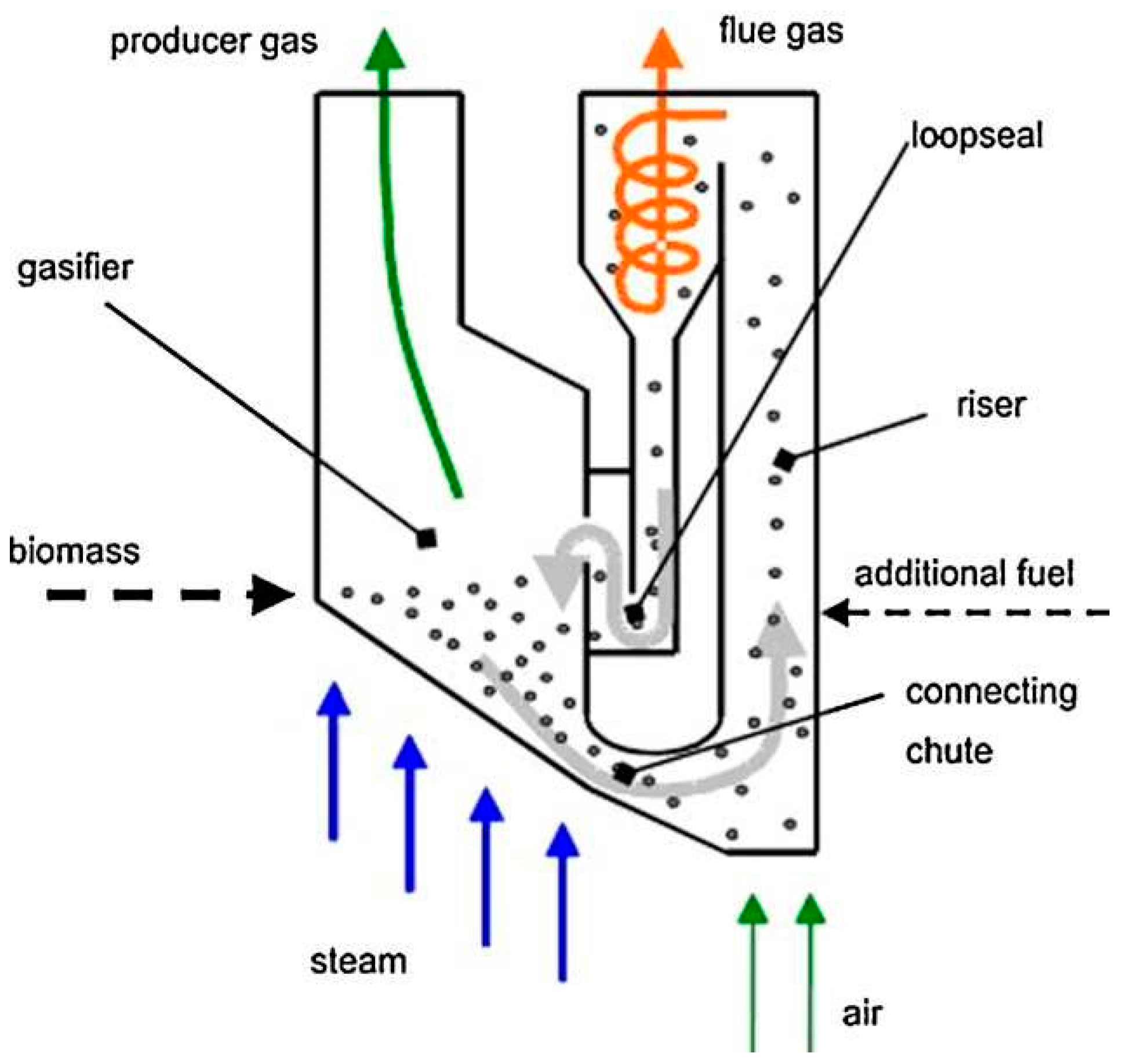
This dual fluidized bed configuration allows for efficient biomass gasification by separating the combustion and gasification processes into different chambers, enabling better control over temperature, gas composition, and reaction kinetics. It provides a versatile and effective system for converting biomass feedstock into valuable syngas for various applications.
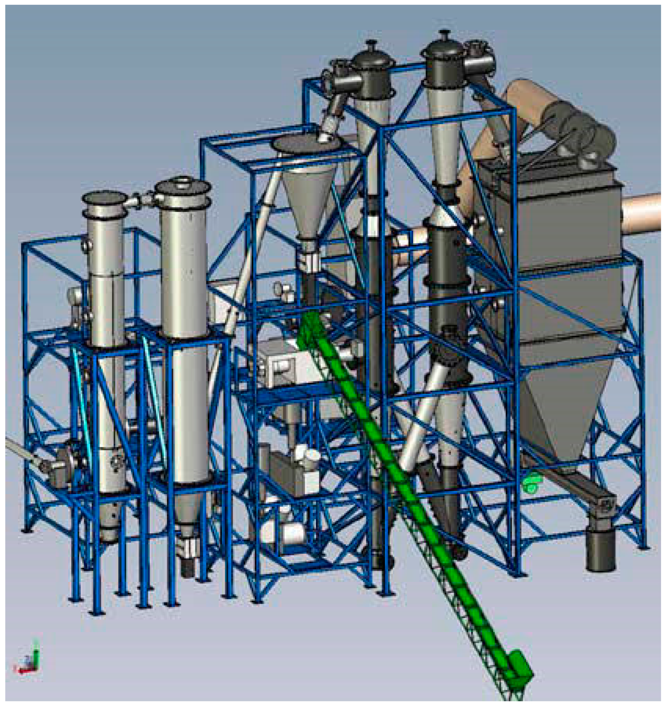
Figure 2.
Circulating Fluidized Bed Gasifier.
2.4. Type of Biomass Gasifiers
There are several types of biomass gasifiers used in the thermochemical conversion of biomass into syngas. Each type of gasifier has its own operating principles, advantages, and limitations. Here are some common types of biomass gasifiers: 1. Updraft Gasifier: In an updraft gasifier, biomass feedstock is introduced at the top of the gasification chamber, and the gasification process proceeds downward. The syngas exits from the top of the gasifier, while ash is collected at the bottom. Updraft gasifiers are simple in design and operation, but they may have limitations in achieving high gasification efficiencies and syngas quality. 2. Downdraft Gasifier: Downdraft gasifiers operate with a downward flow of biomass and gasification agents. The biomass is loaded at the top of the gasifier, and the syngas exits from the bottom. Downdraft gasifiers typically produce high-quality syngas with lower tar content compared to updraft gasifiers. They are known for their efficient operation and good thermal efficiency. 3. Fluidized Bed Gasifier: In a fluidized bed gasifier, a bed of inert material such as sand or ash is fluidized by a stream of air or gas. Biomass feedstock is introduced into the fluidized bed, where it undergoes gasification. Fluidized bed gasifiers offer good mixing of biomass and gasifying agents, leading to efficient and uniform gasification. They are suitable for a wide range of biomass feedstocks and can handle higher moisture content materials. 4. Fixed Bed Gasifier: Fixed bed gasifiers consist of a stationary bed of biomass through which gasifying agents flow. These gasifiers can operate in either an updraft or downdraft configuration. Fixed bed gasifiers are known for their simplicity and reliability, but they may have limitations in terms of gasification efficiency and tar formation. 5. Entrained Flow Gasifier: Entrained flow gasifiers are high-temperature reactors where finely ground biomass particles are suspended in a flow of gasifying agents such as oxygen or air. The entrained biomass particles are rapidly heated and converted into syngas. Entrained flow gasifiers are capable of handling a wide range of biomass feedstocks and can achieve high syngas heating values. 6. Rotary Kiln Gasifier: Rotary kiln gasifiers utilize a rotating cylindrical reactor to convert biomass into syngas. Biomass feedstock is fed into the kiln, where it undergoes gasification under controlled conditions. Rotary kiln gasifiers offer good heat transfer and mixing, leading to efficient biomass conversion. They are suitable for processing high-moisture content biomass. Each type of biomass gasifier has its own set of advantages and considerations, and the choice of gasifier technology depends on factors such as feedstock characteristics, desired syngas properties, operational requirements, and scale of operation. By selecting the appropriate biomass gasifier type and optimizing gasification conditions, researchers and engineers can design efficient and sustainable biomass-to-energy systems.
Figure 3 illustrates the processes of Biomass Energy from wood combustion: 1. **Wood Combustion**: Biomass, such as wood, is combusted in a controlled environment with a reduced amount of air to generate heat. 2. **Gasification**: The combustion process produces a gas stream containing carbon monoxide and hydrogen, which can be further utilized for energy production. 3. **Steam Boiler**: The heat generated from wood combustion or gasification is used to produce steam in a boiler. 4. **Turbine**: The high-pressure steam generated from the boiler is directed towards a turbine. 5. **Generator**: The turbine drives a generator, converting mechanical energy into electrical energy. 6. **Transmission and Distribution**: Electricity generated is transmitted through power lines to various locations for distribution. 7. **Customer**: The electricity reaches the end-users, such as residential, commercial, or industrial consumers, for their energy needs. This process highlights the conversion of biomass, specifically wood, into electricity through combustion, steam generation, turbine operation, and electricity transmission. It showcases the sustainable use of biomass as a renewable energy source for power generation.
2.5. Numerical Model and Development
The development of numerical models plays a crucial role in advancing the understanding and optimization of biomass gasification processes. Numerical models are computational tools used to simulate and analyze the complex thermochemical reactions and transport phenomena that occur during gasification. These models help researchers and engineers predict process performance, optimize operating conditions, and design efficient gasification systems. The development of numerical models for biomass gasification involves several key steps:
Model Formulation: The first step in developing a numerical model for biomass gasification is to formulate the mathematical equations that describe the physical and chemical processes occurring in the gasifier. These equations may include mass and energy balances, reaction kinetics, heat transfer mechanisms, and gas-phase and solid-phase interactions. We consider a simple one-dimensional model for a downdraft biomass gasifier. The biomass feedstock undergoes pyrolysis, gasification, and combustion processes to produce syngas. The model incorporates mass and energy balances, reaction kinetics, and heat transfer mechanisms.
biomass gasification processes, the mass balance equation is a fundamental component of the numerical model used to analyze and optimize the system. The mass balance equation accounts for the conservation of mass within the gasifier reactor and helps track the distribution of biomass components and reaction products.
The general form of the mass balance equation for biomass gasification can be represented as:
where:
[ \frac{dC}{dt} = \sum{i=1}^{n} \left( F{i,in} \cdot C{i,in} - F{i,out} \cdot C{i} \right) + R{bio} ]
- ( C ) represents the concentration of a specific component in the gasifier reactor over time ( t ).
- ( F{i,in} ) and ( C{i,in} ) are the inlet flow rate and concentration of component ( i ) entering the reactor, respectively.
- ( F_{i,out} ) is the outlet flow rate of component ( i ) from the reactor.
- ( R_{bio} ) denotes the rate of biomass conversion reactions occurring within the reactor.
By incorporating the mass balance equation into the numerical model, researchers can track the changes in component concentrations over time and optimize the biomass gasification process for efficient production of desired products like syngas.
Parameter Estimation: An important aspect of model development is the estimation of model parameters, such as reaction kinetics, heat transfer coefficients, and transport properties. Experimental data and literature values are often used to calibrate and validate these parameters to ensure the model accurately represents real-world gasification processes
Parameters such as reaction rates, heat transfer coefficients, and gasification kinetics need to be estimated based on experimental data or literature values.
The energy balance equation accounts for the conservation of energy within the gasifier reactor and helps track the distribution of energy input and output in the form of heat and chemical reactions.
The general form of the energy balance equation for biomass gasification can be represented as:
where:
[ \frac{dE}{dt} = \sum{i=1}^{n} \left( F{i,in} \cdot H{i,in} - F{i,out} \cdot H{i} \right) + Q{in} - Q{out} + \dot{W} + \dot{Q}{bio} ].
- ( E ) represents the energy content in the gasifier reactor over time ( t ).
- ( F{i,in} ) and ( H{i,in} ) are the inlet flow rate and enthalpy of component ( i ) entering the reactor, respectively.
- ( F{i,out} ) and ( H{i} ) are the outlet flow rate and enthalpy of component ( i ) leaving the reactor.
- ( Q{in} ) and ( Q{out} ) denote the energy input and output in the form of heat, respectively.
- ( \dot{W} ) represents the work done on or by the system.
- ( \dot{Q}_{bio} ) signifies the energy released or consumed due to biomass conversion reactions.
By incorporating the energy balance equation into the numerical model, researchers can track the changes in energy content over time, optimize energy utilization, and enhance the overall efficiency of the biomass gasification process. This parameter estimation is crucial for fine-tuning the system and achieving optimal performance.
Numerical Methods: Various numerical methods, such as finite difference, finite element, or computational fluid dynamics (CFD), are employed to solve the mathematical equations governing biomass gasification. These methods discretize the gasifier domain into computational cells or elements, allowing for the calculation of temperature profiles, species concentrations, and other relevant variables.
Finite difference method is used to discretize the gasifier into computational cells. The governing equations for mass and energy conservation, species transport, and reaction kinetics are solved iteratively within each cell.
Reaction kinetics:
[ r = k(T) \cdot C_{\mathrm{biomass}} ]
Reaction Mechanisms: Developing accurate reaction mechanisms is crucial for modeling the complex chemical reactions that occur during biomass gasification. This includes modeling pyrolysis, char conversion, tar formation, and gas-phase reactions. Reaction mechanisms may be based on experimental data or theoretical considerations.The reaction mechanisms include biomass pyrolysis, char conversion, tar formation, and gas-phase reactions. The kinetics of these reactions are represented by Arrhenius equations or other suitable forms..
Species transport
When considering reaction mechanisms and species transport in biomass gasification processes, the transport equations play a crucial role in understanding the movement of various chemical species within the gasifier reactor. These equations help track the concentration gradients of species as they react and interact with each other during the gasification process.
One of the fundamental transport equations used in numerical models for species transport is the general advection-diffusion equation, which can be represented as:
where:
[ \frac{\partial C}{\partial t} + \nabla \cdot (uC) = \nabla \cdot (D \nabla C) + R ]
- ( C ) represents the concentration of a specific chemical species.
- ( t ) denotes time.
- ( u ) signifies the velocity field of the gas phase within the reactor.
- ( D ) is the diffusion coefficient of the species.
- ( R ) represents the net rate of generation or consumption of the species due to chemical reactions.
By solving the advection-diffusion equation along with the corresponding reaction kinetics equations, researchers can model the transport of various species, their interactions, and how they evolve over time within the biomass gasification reactor. This approach helps in understanding the distribution and conversion of species, optimizing reaction mechanisms, and ultimately improving the efficiency and performance of the gasification process.
Validation and verification of heat transfer models are essential steps in ensuring the accuracy and reliability of numerical simulations in biomass gasification processes. Heat transfer plays a crucial role in determining the temperature distribution within the gasifier reactor, influencing reaction rates, product yields, and overall process efficiency.
To validate and verify heat transfer models in the numerical simulation, researchers typically compare the model predictions with experimental data or analytical solutions. This process involves assessing the model's ability to accurately capture heat transfer mechanisms, such as conduction, convection, and radiation, within the gasifier.
Validation involves comparing the numerical model results with real-world measurements to confirm that the model accurately represents the physical system. Verification, on the other hand, focuses on assessing the correctness of the numerical implementation to ensure that the equations are solved correctly and the computational results are reliable.
By rigorously validating and verifying the heat transfer models used in biomass gasification simulations, researchers can have confidence in the predictive capabilities of their numerical tools. This process helps improve the understanding of thermal behavior within the gasifier, optimize operating conditions, and enhance the overall performance of biomass gasification processes.
Sensitivity Analysis: Sensitivity analysis is performed to identify the key parameters and variables that influence gasification performance. This analysis helps in understanding the sensitivity of the model predictions to changes in input parameters and guides optimization efforts.
Sensitivity analysis is performed to identify the parameters that most significantly influence the gasification process. Sensitivity coefficients are calculated to determine the impact of changes in input parameters on the model outputs.
Sensitivity coefficients:
sensitivity coefficients play a crucial role in analyzing the impact of input parameters on the output of numerical models in biomass gasification processes. These coefficients quantify how changes in input parameters affect the model predictions, providing valuable insights into the sensitivity of the system to variations in key variables.
Mathematically, sensitivity coefficients can be defined as the partial derivatives of the model output with respect to the input parameters. They help researchers identify which parameters have the most significant influence on the model results, allowing for targeted sensitivity analyses and optimization efforts.
By calculating sensitivity coefficients, researchers can prioritize input parameters for further investigation, refine model calibration, and improve the overall accuracy of predictions. Sensitivity analyses based on these coefficients enable a better understanding of the system behavior, leading to more informed decision-making in the design and operation of biomass gasification processes.
In essence, sensitivity coefficients serve as valuable tools for identifying critical parameters, optimizing system performance, and enhancing the reliability of numerical models in studying biomass gasification.
Model Optimization: Numerical models can be used for optimization studies to determine the optimal operating conditions for maximizing syngas production, energy efficiency, or minimizing environmental impacts. Optimization algorithms can be applied to the numerical model to identify the best set of parameters for a given objective function.
Optimization algorithms, such as genetic algorithms or gradient-based methods, can be applied to the numerical model to find the optimal operating conditions that maximize syngas production or energy efficiency.
Optimization objective function:
the optimization objective function serves as a key metric that researchers aim to maximize or minimize to achieve the desired outcomes. This function represents the goal of the optimization process and is typically defined based on specific objectives, such as maximizing syngas production, minimizing energy consumption, or optimizing product yields.
The optimization objective function can be formulated using a combination of model variables, constraints, and parameters to reflect the overall performance criteria of the system. It encapsulates the trade-offs and priorities in the optimization process and guides the search for the optimal set of operating conditions or design parameters.
Researchers often use mathematical optimization techniques, such as linear programming, nonlinear optimization, or evolutionary algorithms, to solve the optimization objective function and identify the optimal solution. By iteratively adjusting the input parameters based on the objective function, researchers can fine-tune the system to achieve the desired performance metrics.
Ultimately, the optimization objective function plays a crucial role in guiding decision-making, improving efficiency, and driving innovation in biomass gasification processes by enabling researchers to systematically optimize design and operation for enhanced performance and sustainability

Table 1.
Fundamental Equation of Equilibrium Model.
| 1. Mass Balance Equation |
| Describes the conservation of mass within the system, accounting for the inflow , outflow, and accumulation of mass. It is fundamental in understanding the distribution of species and reactants in biomass gasification processes. |
| 2. Energy Balance Equation |
| Governs the conservation of energy in the system, taking into account heat transfer , chemical reactions, and energy generation or consumption . This equation provides insights into the thermal behavior and energy requirements of the gasification process. |
| 3. Species Transport Equations |
| Models the transport of different species (e.g., gases, vapors, solids) within the reactor, considering diffusion, convection, and chemical reactions. These equations are essential for predicting the distribution and conversion of biomass components during gasification. |
| 4. Reaction Kinetics Equations |
| Describe the rates of chemical reactions taking place in the gasifier, including pyrolysis, combustion and gasification reactions. These equations elucidate the conversion of biomass into syngas and other byproducts, influencing overall process efficiency. |
| 5. Heat Transfer Equations |
| Govern the transfer of heat within the system, including conduction, convection, and radiation. These equations help in analyzing temperature profiles, thermal gradients, and heat distribution within the gasification reactor. |
| 6. Equilibrium Models |
| Utilize thermodynamic equilibrium assumptions to predict the composition of product gases at given operating conditions. These models simplify the complex gasification reactions by assuming equilibrium among species, providing valuable insights into gas composition and equilibrium constants. |
Here are the mathematical representations of the fundamental equations of equilibrium models for The mass balance equation is a fundamental principle that ensures the conservation of mass within the system. This equation accounts for the flow of mass into and out of the gasifier reactor and tracks the distribution of biomass components and reaction products.
The general form of the mass balance equation for biomass gasification can be expressed as:
[ Accumulation = Inflow - Outflow + Generation - Consumption ]
In this equation:
- Accumulation represents the rate of change of mass within the reactor over time.
- Inflow and Outflow denote the flow rates of biomass feedstock or gas species entering and leaving the reactor, respectively.
- Generation and Consumption refer to the rates at which products are generated or consumed due to chemical reactions within the reactor.
By solving the mass balance equation, researchers can predict how the concentrations of different species evolve over time in the gasifier, allowing for the optimization of operating conditions and the design of efficient biomass gasification systems. The mass balance equation serves as a cornerstone for understanding and modeling the complex interactions that occur during the conversion of biomass into valuable products like syngas.
Energy Balance Equation:
The energy balance equation is a fundamental principle that ensures the conservation of energy within the system. This equation accounts for the flow of energy into and out of the gasifier reactor and tracks the distribution of heat and chemical energy associated with biomass conversion.
The general form of the energy balance equation for biomass gasification can be expressed as:
[ \frac{dE}{dt} = \sum{i=1}^{n} \left( F{i,in} \cdot H{i,in} - F{i,out} \cdot H{i} \right) + Q{in} - Q{out} + W{shaft} + \dot{Q}_{bio} ].
In this equation:
- ( E ) represents the total energy content within the reactor over time.
- ( F{i,in} ) and ( H{i,in} ) are the inlet flow rate and enthalpy of component ( i ) entering the reactor, respectively.
- ( F{i,out} ) and ( H{i} ) are the outlet flow rate and enthalpy of component ( i ) leaving the reactor.
- ( Q{in} ) and ( Q{out} ) denote the energy input and output in the form of heat, respectively.
- ( W_{shaft} ) represents the work done on or by the system.
- ( \dot{Q}_{bio} ) signifies the energy released or consumed due to biomass conversion reaction.
By solving the energy balance equation, researchers can predict the thermal behavior within the gasifier, optimize energy utilization, and assess the overall energy efficiency of the biomass gasification process. This equation serves as a critical tool for analyzing and improving the performance of biomass gasification systems from an energy perspective.
In biomass gasification processes, species transport equations are essential for understanding the distribution and transport of different chemical species within the gasifier reactor. These equations help track the movement and interactions of species such as biomass components, intermediates, gases, and ash particles as they undergo conversion and reaction.
The species transport equations are typically based on the principles of conservation of mass and species transport, and they can be expressed as a set of partial differential equations for each species present in the system. The general form of a species transport equation can be written as:
[ \frac{\partial C_i}{\partial t} + \nabla \cdot (\rho u C_i) = \nabla \cdot (\Gamma_i \nabla C_i) + R_i ]
In this equation:
- ( C_i ) represents the concentration of species ( i ) at a given point in space and time.
- ( t ) denotes time.
- ( \rho ) is the density of the gas phase.
- ( u ) signifies the velocity field of the gas phase.
- ( \Gamma_i ) is the species diffusion coefficient.
- ( R_i ) represents the net rate of generation or consumption of species ( i ) due to chemical reactions.
By solving the species transport equations along with reaction kinetics and energy balance equations, researchers can model the dynamic behavior of species within the gasifier, predict reaction pathways, and optimize operating conditions for desired product yields. These equations are crucial for understanding the complex interplay of chemical reactions and transport phenomena in biomass gasification systems.
species Transport Equations:
Reaction Kinetics Equations: [ r = k \cdot C^n ] where:
- ( r ) is the reaction rate,
- ( k ) represents the rate constant,
- ( C ) denotes the concentration of reactants,
- ( n ) represents the reaction order.
Heat Transfer Equations: [ \nabla \cdot (\lambda \nabla T) = \rho c_p \frac{\partial T}{\partial t} + Q - \dot{W} ].
Equilibrium Models: [ Kp = \frac{P{\text{products}}}{P_{\text{reactants}}} ] where:
( K_p ) represents the equilibrium constant,
( P_{\text{products}} ) denotes the partial pressure of products,
( P_{\text{reactants}} ) represents the partial pressure of reactants.
These fundamental equations form the basis for modeling and analyzing equilibrium conditions in biomass gasification processes.
2.6. Model and Kinetics
When developing kinetics models for biomass gasification processes, various software platforms can be utilized to facilitate model construction, simulation, and analysis. These platforms offer different functionalities and capabilities to enhance the efficiency and accuracy of modeling works.One commonly used software tool for kinetic modeling is spreadsheets, such as Microsoft Excel or Google Sheets. Spreadsheets provide a user-friendly interface for performing quick and easy arithmetic calculations, organizing data, and visualizing results. They are particularly useful for preliminary calculations and simple kinetic models in biomass gasification studies.
For more advanced kinetic modeling tasks, numerical solvers and simulation software can be employed. Platforms like Mathematica and MATLAB offer powerful numerical analysis tools, including the ability to solve complex differential equations that govern reaction kinetics in gasification processes. The Ordinary Differential Equation (ODE) toolbox in MATLAB, for instance, provides a wide range of functions and algorithms for solving ordinary differential equations, which are commonly used in kinetics modeling.
By utilizing software platforms like MATLAB, researchers can implement and solve kinetic models of biomass gasification reactions, analyze the impact of different parameters on reaction rates, and optimize process conditions. These tools enable the integration of reaction kinetics, mass and energy balances, and transport phenomena into comprehensive models that capture the dynamics of gasification processes.
In summary, the choice of software platform for kinetics modeling in biomass gasification depends on the complexity of the model, the computational requirements, and the level of detail needed in the analysis. Spreadsheets are suitable for simple calculations and data organization, while numerical solvers like MATLAB provide advanced capabilities for solving complex differential equations and conducting in-depth simulations. Researchers can leverage these software tools to enhance their understanding of biomass gasification kinetics and optimize process design for sustainable energy production..
Figure 4.
Fluidized bed gasifier zones.
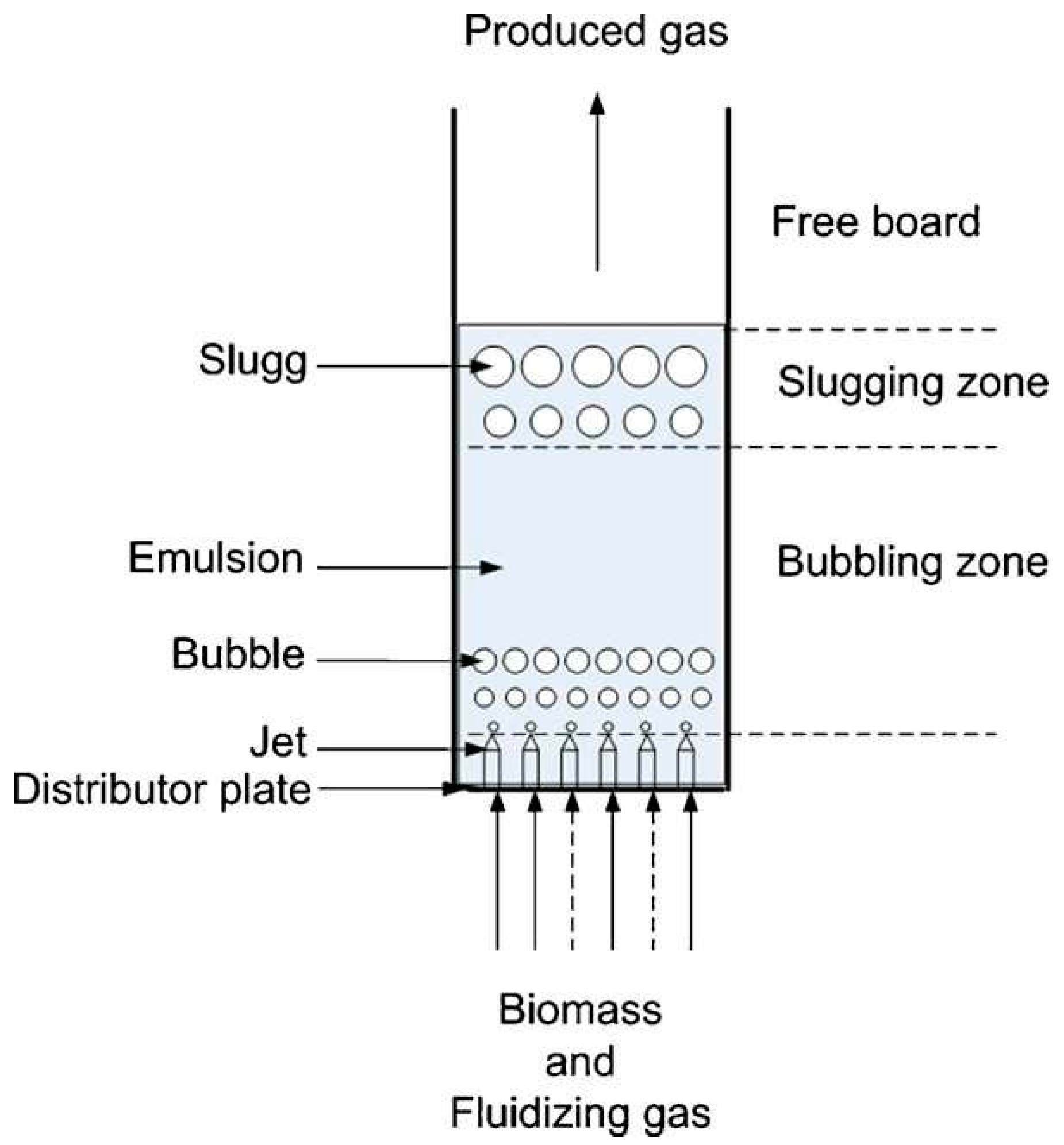
In a Fluidized Bed Gasifier, The Different Zones Include:
- Biomass and Fluidizing Gas Zone: This is where the raw biomass material is introduced along with the fluidizing gas, such as air or steam, which helps in fluidizing the bed of particles.
- Bubbling Zone: In this region, the fluidized bed exhibits bubbling behavior due to the gasification reactions and the circulation of gases and particles within the bed.
- Freeboard: The area above the fluidized bed where gasification reactions continue in the presence of oxygen, leading to the production of syngas.
- Slugging Zone: This zone may experience intermittent churning or slugging behavior, characterized by the movement of large clusters of particles and gases within the bed.
- Emulsion: Refers to the region where gas-solid mixing and reactions occur, facilitating the conversion of biomass into syngas.
- Distributor Plate: A component that helps in distributing the fluidizing gas evenly across the bed and maintaining the fluidized state.
- Jet: Represents the injection point for the fluidizing gas to enter the bed and maintain the desired fluidization characteristics.
- Slugs: Refers to the clusters or agglomerates of particles that move within the bed, impacting the gas-solid interactions and reaction kinetics.
These zones play a crucial role in the efficient operation of a fluidized bed gasifier, ensuring proper mixing, heat transfer, and gas-solid interactions essential for biomass gasification and syngas production..It is crucial to re-evaluate the kinetics models for biomass gasifiers reported in the literature to assess their compliance, accuracy, and adaptability to various reactor configurations. By classifying these models based on the types of gasifiers considered in the studies, a comprehensive understanding of their performance can be achieved. The profiling of product gas compositions against empirical results provides valuable insights into the predictive capabilities of these models. Numerical models play a pivotal role in understanding the complex kinetics of biomass gasification processes. These models vary in their level of compliance with experimental data, accuracy in predicting gasification outcomes, and adaptability to different reactor configurations. The diverse nature of biomass feedstocks and gasifier designs necessitates models that can capture the intricacies of the gasification reactions effectively. By scrutinizing and categorizing the existing numerical models based on gasifier types and their performance in predicting product gas compositions, researchers can identify the strengths and limitations of each model. This re-appraisal can lead to improvements in model development, calibration, and validation, ultimately enhancing the overall understanding of biomass gasification kinetics. Overall, the evaluation and comparison of numerical models for biomass gasification kinetics are essential for advancing the field, improving model accuracy, and guiding future research efforts towards developing robust and versatile models that can effectively simulate a wide range of gasification systems and conditions.
2.7. Artificial Neural Network Models
Artificial Neural Networks (ANNs) have gained popularity in modeling complex systems, including biomass gasification processes. ANNs are computational models inspired by the structure and functioning of the human brain, consisting of interconnected nodes (neurons) that process and transmit information. In the context of biomass gasification, ANNs can be used to capture nonlinear relationships, predict system behavior, and optimize process parameters. Here's how ANNs can be applied in modeling biomass gasification:
Model Development: ANNs can be trained to learn the complex relationships between input variables (e.g., biomass composition, operating conditions) and output parameters (e.g., syngas composition, gasifier temperature). By presenting a dataset of input-output pairs to the network, the model learns to map the input data to the desired output, enabling it to make predictions for unseen data.
Nonlinear Mapping: Biomass gasification processes exhibit nonlinear behavior due to the intricate interactions of multiple variables. ANNs excel at capturing nonlinear patterns in the data, allowing for accurate modeling of the complex relationships between process variables and outcomes. This makes ANNs well-suited for representing the dynamic nature of gasification reactions.
Prediction and Optimization: Once trained, ANNs can be used to predict various outcomes of biomass gasification, such as syngas composition, heating value, or tar content, based on input parameters. Additionally, ANNs can be employed in optimization tasks to find the optimal operating conditions that maximize syngas yield or energy efficiency.
Data-Driven Approach: ANNs are particularly effective in data-driven modeling, where large datasets of experimental or simulated data are available. By training on diverse datasets, ANNs can generalize well and provide robust predictions for different scenarios, helping researchers gain insights into the underlying processes of biomass gasification.
Model Interpretability: While ANNs are known for their black-box nature, efforts can be made to interpret the learned relationships within the network. Techniques such as sensitivity analysis or visualization of the network's internal layers can provide insights into the factors driving the gasification process.
Figure 5.
Artificial Neural Network :.
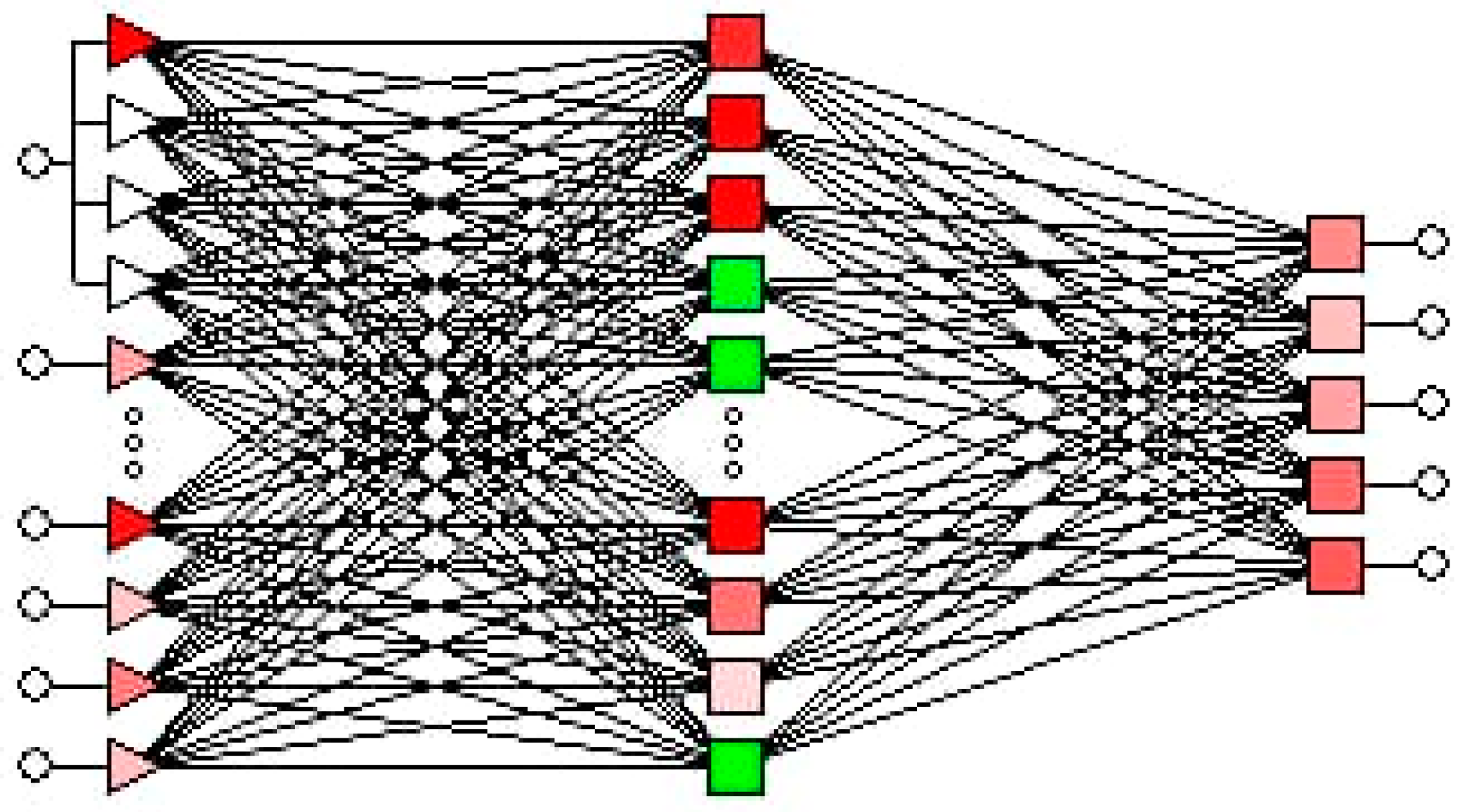
The Artificial Neural Networks offer a powerful and versatile tool for modeling biomass gasification processes. By leveraging the capabilities of ANNs, researchers can develop accurate predictive models, optimize process parameters, and gain a deeper understanding of the complex dynamics involved in biomass gasification.
In Figure 6, In a biomass gasification power plant system as described in Figure 6, the key components and processes are as follows: 1. **Fuel Handling System**: This system is responsible for handling and preparing the biomass feedstock for the gasification process. 2. **Two Gasifiers**: The gasification process takes place in two gasifiers, where the biomass feedstock is converted into syngas through high-temperature reactions with a controlled amount of oxygen or steam. 3. **Boiler**: The syngas produced in the gasifiers is used as a fuel in the boiler to generate high-pressure steam. 4. **Economizer**: The economizer recovers waste heat from the boiler flue gases to preheat the feedwater, increasing the overall thermal efficiency of the system. 5. **Syngas Ignition Chamber**: This chamber is where the syngas is ignited to initiate combustion for heat and power generation. 6. **Electrostatic Precipitator (ESP)**: The ESP is a pollution control device that removes particulate matter and dust from the flue gas before it is released into the atmosphere. 7. **Stack**: The stack acts as an exhaust outlet for the combustion byproducts and gases emitted from the system. This biomass gasification power plant system demonstrates the conversion of biomass into syngas through gasification and its subsequent utilization in a boiler for steam generation and power production. The integration of gasification technology with efficient boiler systems and pollution control devices ensures sustainable and environmentally friendly energy generation from biomass resources.
3. Results and Discussion
3.1. Model and Process Simulation
Process simulation software plays a vital role in modeling and analyzing complex systems like biomass gasification processes. These software tools offer a range of features for designing, simulating, and optimizing various aspects of the gasification system. Here are some examples of process simulation software commonly used in the industry:
- ➢
- SuperPro Designer: SuperPro Designer is a comprehensive process simulation software that allows users to model and optimize a wide range of processes, including biomass conversion. It offers capabilities for designing process flowsheets, conducting mass and energy balances, and performing techno-economic analysis.
- ➢
- Pro/II: Pro/II is a powerful process simulation software widely used in the chemical and energy industries. It enables users to create detailed process models, simulate complex reactions, and analyze system performance. Pro/II can be applied to simulate biomass gasification processes and evaluate different operating scenarios.
- ➢
- ChemCad: ChemCad is another popular simulation software known for its chemical process modeling capabilities. It provides tools for simulating chemical reactions, heat and mass transfer, and equipment sizing. ChemCad can be utilized to model biomass gasification reactions and optimize process parameters.
For dynamic simulation, software tools like MATLAB and ANSYS Fluent/CFX are commonly employed due to their advanced capabilities in solving differential equations and simulating fluid flow and heat transfer. These software platforms are particularly useful for analyzing transient behavior, time-dependent processes, and system response to changing conditions.
- ➢
- MATLAB: MATLAB is a versatile programming environment that offers powerful numerical computation capabilities. It is often utilized for dynamic simulation of biomass gasification processes, where complex reaction kinetics, heat transfer, and mass transport phenomena need to be modeled and analyzed.
- ➢
- ANSYS Fluent and ANSYS CFX: ANSYS Fluent and ANSYS CFX are leading computational fluid dynamics (CFD) software packages used for simulating fluid flow, heat transfer, and chemical reactions. They are ideal for studying gas-solid interactions, combustion processes, and thermal behavior in biomass gasifiers.
- ➢
- CFD2000: CFD2000 is a specialized CFD software tailored for modeling combustion and gasification processes. It offers features for simulating fluidized bed reactors, particle dynamics, and chemical reactions, making it suitable for analyzing biomass gasification systems.
By utilizing these process simulation software tools, researchers and engineers can develop detailed models of biomass gasification processes, simulate system behavior under different conditions, optimize process parameters, and ultimately design efficient and sustainable energy production systems..
3.2. Analytical Fluid Dynamics Simulation Models
Process Optimization.
Analytical fluid dynamics simulation models are instrumental in studying the flow behavior, heat transfer, and chemical reactions within biomass gasification systems. These models utilize mathematical equations to describe the fluid flow dynamics, energy transfer, and species transport in gasifiers. By leveraging analytical fluid dynamics simulations, researchers can gain insights into the complex phenomena occurring during biomass gasification. Process optimization in biomass gasification involves maximizing syngas production, energy efficiency, and overall system performance while minimizing environmental impacts. Optimization strategies aim to identify the optimal operating conditions, reactor configurations, and feedstock compositions that yield the most desirable outcomes. Here's how analytical fluid dynamics simulation models can be utilized for process optimization in biomass gasification: 1. **Virtual Experiments**: By setting up virtual experiments using analytical fluid dynamics simulations, researchers can explore a wide range of operating parameters and scenarios without the need for physical prototypes. This allows for rapid evaluation of different process configurations and facilitates the identification of optimal conditions. 2. **Sensitivity Analysis**: Analytical fluid dynamics models can be used to perform sensitivity analyses to understand how changes in key parameters affect gasification performance. By evaluating the impact of variables such as temperature, residence time, and feedstock composition on syngas quality and production rates, researchers can optimize process settings. 3. **Design Optimization**: Through iterative simulations and design modifications, analytical fluid dynamics models can assist in optimizing the geometry and layout of gasification reactors. Researchers can evaluate the impact of reactor design parameters on fluid flow patterns, heat distribution, and reaction kinetics to enhance system efficiency. 4. **Reaction Kinetics Optimization**: Analytical fluid dynamics simulations can incorporate detailed reaction kinetics models to optimize the conversion of biomass into syngas. By adjusting reaction rates, species concentrations, and temperature profiles, researchers can fine-tune gasification processes to maximize product yields and quality. 5. **Performance Prediction**: By coupling analytical fluid dynamics simulations with process optimization algorithms, researchers can predict the performance of biomass gasification systems under varying conditions. This predictive capability enables informed decision-making and facilitates the development of efficient and sustainable gasification processes. Overall, analytical fluid dynamics simulation models provide a powerful tool for optimizing biomass gasification processes by enabling detailed analysis of fluid flow dynamics, heat and mass transfer, and chemical reactions. Through process optimization strategies guided by analytical simulations, researchers can enhance the efficiency, productivity, and environmental sustainability of biomass gasification systems.
3.3. Heat Integration
Heat integration plays a critical role in optimizing the efficiency and sustainability of biomass gasification processes. By strategically designing and implementing heat integration systems, researchers and engineers can maximize energy recovery, reduce resource consumption, and enhance overall process performance. Here's how heat integration can be applied in biomass gasification: 1. **Heat Recovery**: In biomass gasification, heat integration involves capturing and utilizing waste heat generated during various process steps. By recovering excess heat from gasification reactions, syngas cleaning, and gas purification stages, the energy can be recycled and used to preheat feed streams, generate steam, or drive auxiliary processes. 2. **Process Integration**: Heat integration techniques can be employed to integrate different process units within the gasification plant, allowing for efficient heat exchange and utilization. By optimizing the thermal connections between reactors, heat exchangers, and heat recovery units, overall energy efficiency can be improved while reducing operating costs. 3. **Heat Exchangers**: The design and placement of heat exchangers are crucial in heat integration strategies. By utilizing heat exchangers to transfer heat between hot and cold streams, thermal energy can be effectively distributed within the system. Different types of heat exchangers, such as shell-and-tube or plate heat exchangers, can be selected based on process requirements. 4. **Pinch Analysis**: Pinch analysis is a powerful tool used in heat integration to identify optimal temperature levels for heat exchange. By pinpointing the "pinch point" where hot and cold streams can be efficiently matched, engineers can design heat exchanger networks that minimize energy losses and maximize heat recovery. 5. **Cogeneration**: Heat integration in biomass gasification can also involve cogeneration, where surplus heat is used to generate electricity or produce additional valuable products. By combining power generation with heat recovery, cogeneration systems can enhance the overall energy efficiency and economic viability of gasification plants. 6. **Thermal Integration Software**: Advanced thermal integration software tools, such as Aspen Energy Analyzer or Heat Integration Software (HIS), can be utilized to model, simulate, and optimize heat integration strategies in biomass gasification processes. ..
These tools enable engineers to analyze heat transfer networks, identify energy-saving opportunities, and optimize process design for maximum efficiency. By implementing heat integration strategies in biomass gasification processes, researchers and engineers can improve energy efficiency, reduce carbon emissions, and enhance the overall sustainability of biomass-to-energy conversion. Effective heat integration can lead to significant cost savings, resource conservation, and environmental benefits, making it a key aspect of optimizing biomass gasification systems.
In Figure 7, In a biomass plant with heat integration and thermal plasma technology, Figure 6 illustrates the following components and processes: 1. **MSW Feeding System**: The Municipal Solid Waste (MSW) feeding system introduces waste materials into the system for processing. 2. **Thermal Plasma Torches**: Thermal plasma torches are used to initiate high-temperature plasma reactions for efficient waste treatment and gasification. 3. **Integrated Thermal Plasma Furnace**: The integrated thermal plasma furnace utilizes the high temperature of plasma to gasify and convert the biomass or waste feedstock into syngas. 4. **Heat Exchanger**: The heat exchanger captures and transfers thermal energy from the syngas production process to preheat incoming feed materials or generate steam for power generation. 5. **Bag Filter**: A bag filter system is employed to remove particulate matter and impurities from the syngas stream before further processing. 6. **Water Quench and Scrubber**: The water quench and scrubber system cools down the syngas, removes tar and contaminants, and cleans the gas stream before it is used for combustion or other applications. 7. **Syngas Combustion Chamber**: The syngas combustion chamber is where the cleaned syngas is burned to produce heat or power for various industrial processes. 8. **Stack**: The stack serves as an exhaust outlet for the combustion byproducts and gases emitted from the system. By integrating thermal plasma technology with heat recovery systems and gas cleaning processes, this biomass plant design aims to maximize energy efficiency, reduce emissions, and effectively convert biomass or waste materials into valuable syngas for energy production and other applications..
3.4. Co-Generation Potential
Co-generation, also known as Combined Heat and Power (CHP), is a highly efficient power generation system that enhances overall system efficiency. Although the various advantages of co-generation technology, including energy, economic, and environmental benefits, are widely recognized, the direct combustion of biomass or fossil fuels for co-generation applications is not regarded as appealing due to stringent emission regulations.Therefore, it is anticipated that environment-friendly hydrogen derived from biomass will play a significant role in replacing fossil fuels in CHP generation applications. The use of biomass as a fuel in co-generation systems is considered a crucial energy technology for the future, as it combines the advantages of renewable energy sources and hydrogen energy systems . Additionally, studies indicate that the proportion of biomass in combined heat and power generation is expected to rise in the future, with a growing emphasis on decentralized combined heat and power plants.
There are several viable options available for biomass-based Combined Heat and Power (CHP) systems in the output range of 1MWe, including internal combustion engines, micro-gas turbines, and fuel cells . An early application of biomass-based CHP is the Integrated Gasification Combined Cycle (IGCC).,Indeed, there has been a shift in recent times. Researchers have explored biomass gasification for hydrogen production, integrating it with power generation technologies such as evaporative gas turbines , micro-turbines , fuel cells and gas engines . This integrated approach holds great potential for sustainable energy systems.
Ongoing research and development efforts are focused on enhancing gas turbine technology for efficient utilization of hydrogen (H2) and H2-rich gases . Fuel cells, on the other hand, are emerging as a crucial component in the transition towards renewable energy across various utility and mobile applications. An especially promising method to obtain the necessary hydrogen is through biomass gasification. In a separate comprehensive study, Rosen and Scott explored the co-generation potential of different fuel cell systems, including phosphoric acid and alkaline fuel cells.
Various types of fuel cells, including phosphoric acid, alkaline, solid polymer electrolyte, molten carbonate, and solid oxide fuel cells (SOFC), have been extensively studied for hydrogen-fueled fuel cell applications using energy and exergy analysis. Molten carbonate fuel cells (MCFC) and solid oxide fuel cells (SOFC) show the most promise. This is attributed to their high operating temperature levels, flexibility in utilizing different fuels, and greater tolerance to contaminants.
While biomass gasification processes are commonly integrated with gas turbine-based combined heat and power generation systems, the efficiency can be significantly improved by incorporating more advanced power generation technologies like Solid Oxide Fuel Cells (SOFC) . Three combined heat and power systems based on biomass gasification were investigated. In the first system, the product gas from biomass gasification is converted in a micro gas turbine (MGT."In the second system, the product gas from biomass gasification is directed into a solid oxide fuel cell (SOFC), while in the third system, a combined SOFC-MGT configuration is employed. Furthermore, pressurizing the SOFC enhances efficiency, with reported values reaching as high as el = 50.3%. The study also highlights that an optimal operating pressure ratio of 2.5 is observed for the SOFC-MGT combination.. When incorporating fuel cells into biomass gasification, key performance factors that can be explored for different system configurations and cell parameters include fuel utilization, fuel flow rate, operational voltage, and the extent of internal fuel reforming . These figures are crucial in assessing the co-generation potential of such integrated systems.
4. Conclusion
1 **Numerical Modeling Significance**: Throughout the literature review and re-appraisal, it is evident that numerical models have been instrumental in advancing our understanding of biomass gasification processes. These models have not only facilitated predictions of system behavior but have also provided valuable insights into the complex thermodynamic, kinetic, and transport phenomena governing gasification reactions. By leveraging numerical models, researchers have been able to optimize process parameters and enhance the efficiency of hydrogen production as an energy carrier. 2. **Simulation Models for Process Understanding**: Simulation models have proven to be invaluable tools for gaining a comprehensive understanding of biomass gasification systems. By simulating the intricate interactions of biomass feedstocks, reaction kinetics, heat transfer, and gas-solid flows, researchers have been able to assess system performance, identify bottlenecks, and propose improvements. Simulation models have enabled the exploration of various operating conditions and reactor configurations, leading to optimized gasification processes for hydrogen production. 3. **Importance of Heat Integration and Co-generation**: The incorporation of heat integration and co-generation strategies in biomass gasification processes has been highlighted as a key factor in enhancing energy efficiency and overall sustainability. By effectively recovering and utilizing waste heat, optimizing thermal connections, and implementing cogeneration systems, researchers have been able to maximize energy recovery, reduce resource consumption, and enhance the economic viability of hydrogen production from biomass gasification. 4. **Optimization for Enhanced Performance**: Process optimization methodologies have been pivotal in improving the performance of biomass gasification processes for hydrogen production. Through the use of optimization techniques, researchers have been able to identify optimal operating conditions, reactor designs, and feedstock compositions that maximize hydrogen yield and energy efficiency. Optimization studies have facilitated the development of cost-effective and environmentally friendly gasification systems. In conclusion, the integration of numerical models, simulation models, heat integration, co-generation strategies, and optimization techniques has significantly contributed to the advancement of hydrogen production as an energy carrier through biomass gasification. By harnessing the capabilities of these tools and methodologies, researchers have made substantial progress in improving the efficiency, sustainability, and economic feasibility of biomass-to-hydrogen conversion processes. Moving forward, continued research and innovation in these areas will be essential for further enhancing the viability and scalability of hydrogen production from biomass gasification.
4.1. Recommendation
Based on the research findings discussed in this paper, several recommendations can be made:
1. Continued Research and Development: The research findings highlight the potential of computational and mathematical techniques in optimizing biomass gasification processes for hydrogen production. It is recommended to continue investing in research and development to further advance these techniques, improve their accuracy, and explore new approaches for optimizing process efficiency and performance.
2. Technological Innovation: Encouraging technological innovation is crucial to enhance the commercial viability and scalability of biomass gasification for hydrogen production. It is recommended to invest in the development of novel reactor designs, catalysts, and process configurations that can maximize hydrogen yield, improve energy efficiency, and minimize environmental impacts.
3. Collaboration and Knowledge Exchange: Foster collaboration among researchers, industry stakeholders, and policymakers to facilitate knowledge exchange and accelerate the deployment of biomass gasification technologies. This can be achieved through collaborative research projects, workshops, conferences, and platforms for sharing best practices and lessons learned.
4. Policy Support and Incentives: Governments and policymakers should provide policy support and incentives to promote the adoption of biomass gasification technologies for hydrogen production. This can include financial incentives, tax breaks, research grants, and regulatory frameworks that encourage sustainable energy practices and support the transition to a hydrogen-based economy.
5. Education and Awareness: Enhancing education and awareness about the potential of biomass gasification for hydrogen production is crucial. It is recommended to incorporate relevant topics into educational curricula at all levels and to conduct public awareness campaigns to educate individuals and communities about the benefits and feasibility of sustainable energy solutions.
6. Demonstration Projects and Pilot Plants: Encouraging the development of demonstration projects and pilot plants can help validate the feasibility and scalability of biomass gasification technologies for hydrogen production. These projects can serve as real-world examples and provide valuable data for further research and commercial deployment. By implementing these recommendations, we can accelerate the development and adoption of biomass gasification technologies for hydrogen production, contributing to sustainable energy systems, climate action, and the achievement of global sustainable development goals.
Acknowledgments
I would like to express my sincere gratitude to all those who have supported and contributed to this project. Special thanks to ,Johnson global scientific library.for their guidance and expertise throughout the research process. I am also thankful to my colleagues and friends for their valuable insights and encouragement. Additionally, I acknowledge the funding support provided for this project. This work would not have been possible without the collective efforts and support of everyone involved.
References
- Börjesson, P., & Tjerneld, F. (2008). Life cycle assessment of biofuels in the European context (Vol. 42). Heidelberg: Springer Science & Business Media.
- Demirbas, A. (2004). Combustion characteristics of different biomass fuels. Progress in Energy and Combustion Science, 30(2), 219-230. [CrossRef]
- Hossain, M. A., & Davies, P. A. (2015). Biomass energy and the environmental impacts associated with its production and utilization. Environmental Sustainability, 3(1), 82-94.
- Knoef, H. A. M. (2005). Gasification: An alternative process for energy recovery and disposal of municipal solid wastes. Waste Management & Research, 23(4), 281-292.
- Mooney, C. A., Mansfield, S. D., & Beatson, R. P. (2002). Cellulose utilization for ethanol production: enzymatic hydrolysis of cellulosic biomass. Cellulose, 9(4), 445-450.
- Ometto, A. R., & König, A. (2017). Optimization of biomass gasification for power production: A combined numerical and experimental approach. Biomass and Bioenergy, 97, 153-165.
- Ptasinski, K. J., & Prins, M. J. (2011). Coverage of the biomass-to-power amendment by the Dutch renewable energy directive. Renewable Energy, 36(3), 1084-1086.
- Ramanan, R. N., Tan, K. T., Aroua, M. K., & Sulaiman, N. M. N. (2007). Utilization of oil palm as a source of renewable energy in Malaysia. Renewable and Sustainable Energy Reviews, 11(6), 1366-1377.
- Srinivas, T., & Reddy, B. V. (2012). Biomass gasification for decentralised power generation: The Indian perspective. Energy for Sustainable Development, 16(3), 237-244.
- Tabatabaei, M., & Kianmehr, M. H. (2015). A review on comprehensive thermo-economic analysis and optimization of biomass-based polygeneration systems. Renewable and Sustainable Energy Reviews, 52, 205-225.
- Tilman, D., Hill, J., & Lehman, C. (2006). Carbon-negative biofuels from low-input high-diversity grassland biomass. Science, 314(5805), 1598-1600. [CrossRef]
- Tiwari, P., Kumar, A., & Raheman, H. (2007). Biodiesel production from jatropha oil (Jatropha curcas) with high free fatty acids: an optimized process. Biomass and Bioenergy, 31(8), 569-575. [CrossRef]
- Uslu, A., & Faaij, A. (2010). Exploring the prospects for gasification-based energy systems in Turkey. Energy Policy, 38(11), 7151-7161.
- Van der Veen, S., & Junginger, M. (2011). Policy issues related to the development and diffusion of biofuels in the EU. Renewable and Sustainable Energy Reviews, 15(9), 4364-4384.
- Wang, H., Luo, Y., Fan, M., & Chen, L. (2007). Optimization of the biomass gasification process based on equilibrium calculations. Chemical Engineering Journal, 132(1-3), 119-124.
- Xue, J., Koo, Y., & Wu, C. (2012). Optimization of biofuels supply chain and land use under biomass price uncertainty. Biomass and Bioenergy, 46, 349-363.
- Yacob, S., Zhang, M., & Zhang, J. (2014). The prospects of biofuels in Malaysia. Bioresource Technology, 170, 495-503.
- Zainal, Z. A., Ali, R., Lean, C. H., & Seetharamu, K. N. (2001). Prediction of performance of a downdraft gasifier using equilibrium modeling for different biomass materials. Energy Conversion and Management, 42(12), 1499-1515. [CrossRef]
- Abada, E. H., & Avila, C. A. (2016). Techno-economic analysis of a biomass gasification-based power plant with polygeneration options. Energy Conversion and Management, 114, 23-38.
Figure 3.
processes of Biomass Energy.
Figure 6.
Biomass Gasification power plant system.
Figure 7.
Heat Integration of Biomass plant.
Disclaimer/Publisher’s Note: The statements, opinions and data contained in all publications are solely those of the individual author(s) and contributor(s) and not of MDPI and/or the editor(s). MDPI and/or the editor(s) disclaim responsibility for any injury to people or property resulting from any ideas, methods, instructions or products referred to in the content. |
© 2024 by the authors. Licensee MDPI, Basel, Switzerland. This article is an open access article distributed under the terms and conditions of the Creative Commons Attribution (CC BY) license (http://creativecommons.org/licenses/by/4.0/).
Copyright: This open access article is published under a Creative Commons CC BY 4.0 license, which permit the free download, distribution, and reuse, provided that the author and preprint are cited in any reuse.


