Submitted:
25 April 2024
Posted:
26 April 2024
You are already at the latest version
Abstract
The main challenges in oil platforms are how to define optimal setpoints and decision-making for controlling variables due to many existing dynamical production uncertainties while conceding safe operation and minimizing discharge to sea and atmosphere without killing plantwide inventory. A novel scheduling model to optimize the whole essential units of an oil platform production gathering topside and subsea variables is disclosed. A proper topside and subsea scheduling model enables and creates harmony between optimal production, supply chain, costs, and market dynamics, satisfying demands, environmental and operations constraints leading to stability. The interest of the present research lies in determining the optimal topside and subsea operational settings and decision-making, establishing maximum E&P performance and production control setpoints while predicting and manipulating reservoir lifespan and its revitalization. This objective is attained through a novel multiperiod large-scale model for the planning and operational production scheduling and model predictive control (MPC) in oil platforms complying with sustainability, profitability, platform design capacities, and offloading of oil and gas to supply chains or to pipeline exportation. The present model details heat and mass transfer, PVT, flow profiles along a planning horizon and can be used to any oil platform since comprises all the essential unit operations for oil, gas, CO2, H2S and water. The model maximizes the total oil production over any planning horizon. The model is versatile, and decision-making can be either linear or nonlinear but rather a MILP or LP as best choice on optimizing large-scale systems. If the model is applied with auto rescheduling on site within variable hours or minutes, it becomes a real-time optimization schedule approach. Due to its high-velocity performance and robustness, a novel multi-objective function strategy, acting as an LP generic plantwide MPC with industrial scope to maximize production while controlling the process is presented, and as an example is here used to control slug flow to avoid equipment trips and inventory instability, at the same time production is maximized. The output from the decision-making was compared to actual plant data, and the results proved compliance to the design capacity with process safety and sustainability. Comparing to official Brazil's government data for oil, the case study showed superiority to the same size platforms, like FPSOs P-75 and MV32, e.g., more than 101.5% more capacity to produce oil in beginning of campaign after first oil, and 10.5% during campaign. The present work indicates that: 1) the production of millions of barrels is being delayed or left aside; 2) not scheduling production harms the environment and diminish process safety; 3) not scheduling production can create stochastic supply chain deliveries instead of organizing it by deterministic offloading days; 4) scheduling is essential to manipulate, revitalize and monitor reservoir's pressure and content under uncertainty; 5) the oil platform can be automatic optimized by a plantwide MPC reducing human activity/dependency; 6) scheduling gives more transparency to stakeholders and contractors by forecasting business data and capability, and can design, develop or enable new businesses.
Keywords:
topside
; subsea
; planning and scheduling
; plantwide model predictive controller
; optimization under uncertainty
1. Introduction
Decreasing pollution is a matter of process mapping and control, and for this, production needs to rise to optimal and rigorous schedule levels. Oil companies have or will have difficulty in minimizing carbon footprints at the same time profit is the main objective if not having the know-how needed to reconcile oil production maximization and sustainability. A practical example is the increasingly expensive fines imposed due to flaring and other types of environmental pollution. Specifically, kind companies focus primarily on profit to become competitive in the market. A must-know is that is possible to maximize production while controlling the process with sustainability as the world demands. For accomplishing this target, planning and scheduling or a due MPC is necessary to provide a proper production optimization with such constraints and inventory control. Extracting the utmost of a platform's oil production gives the degree of freedom to determine competitive pricing, a possibility enabled from production scheduling for optimal operations.
Oil and gas are essential since battery resources are limited and electrical infrastructure/supply is inaccessible to all world's population. A lack in their supply, especially in oil, would culminate in a need for more power generation, which is currently limited. According to the International Energy Agency (IEA, 2023) oil and gas represents more than half of the world's energy matrix, and oil around one third, in a growing population of 8 billion people. Yet with an ambitious goal to peak oil by 2030, it is not clear yet considering new discoveries, increasing demand for energy, broad uncertainties, politics and wars. However, offshore platforms generally operate below their maximum design capacity and have different results due to geological aspects and production behaviors. It is trivial to see oil platforms with different overall efficiency. At the same time, most of them do not usually reach the current maximum total subsea production capacity whenever they have a plant start-up and delay too much to achieve steady-state regimes. Millions of barrels of oil are not being produced daily due to uncertainties, dynamics, modeling gaps, equipment trips, heuristics and inaccurate standardizations. Scheduling production is the determinant factor to deeply understand the business and scale it to an optimal overall efficiency, avoiding heuristics like manual override or wrong/inefficient setpoints, and organizing production while solving the challenge to fulfill world's energy demand reconciling with minimization of emissions. Without scheduling or feedforward controlling with optimality, profitable and safe operation while minimizing discharge to sea and atmosphere with inventory control is unlikely and ungranted. There are a lot of unnecessary emissions occurring daily.
Becoming neutral in carbon using oil or gas as fuel is not possible, but a more sustainable facility must consider an optimal scheduling aligning production with minimal environmental harm. A more sustainable oil production can be granted when scheduling and can involve the following steps: reinjecting produced CO2 into injection wells; burning only the necessary gas for electricity generation; reinjecting CO2 product from turbogenerators into the wells; minimizing water disposal overboard by optimizing lifted seawater and injection; controlling inventories aligned with capacities to a level for which equipment trips are well avoided and flaring is minimized or even null; considering renewable energies to minimize burning fuels. For this reason, a sustainable decision-making model is presented with these features and considering the maximization of oil for more profit.
After the drilling is done and the wells assignment is made, oil platforms that are not following planning and scheduling models often operate with overloaded capacity or below maximum capacity, and with inventory control challenges that culminate in water disposal to the sea, flaring undesirable amounts of gas and facing unplanned halts. In this case, maximizing production is a big challenge. These scenarios are uncertainties coming with issues like equipment trips. Scheduling operations are essential to 1) ensure inventory control; 2) revitalization of the reservoir and for making sure of its integrity; 3) compliance with flow assurance; 4) non-violation of equipment capacities; 5) satisfy demand filling dynamic gaps as of per supply chain demands; and 6) maximizing profit, optimizing thermodynamics and minimizing emissions. There is a gap in the literature comprising the solution for these combined issues and the present paper intends to fill it by an integrated topside and subsea constrained production/operational model also including inequalities for a more realistic approach.
An important note is that the real optima lie anywhere between a bounded problem, and any unconstrained approach gives favorable conditions that in practice cannot occur. Therefore, any literature's approach not considering inequalities not really will be capable of representing the real optimality as killing inventory or equipment capacity could happen. For oil platforms, constrained operational scheduling is remarkably an excellent strategy since subsea maximum capacity cannot be exploited if topsides operation cannot handle such charge. Moreover, a production scheduling under uncertainty or proper MPC can optimally determine the valves' mass flow setpoints or opening percentages for more realistic representation as it is in practice, i.e., to determine their actual optimal operational setting. Besides that, supply chain costs are considerably increased if inventory routing does not comply with optimal trips with full cargo capacity and oil storage/production, even though oil offloading is monotonic. As far as we know, the present study is the first production scheduling at an operational level considering topside, subsea and reservoir constraints with oil and gas supply chain offloading. A generic plantwide MPC is also presented for process systems control and production maximization, in which the difference compared to the scheduling model is in its objective function and attached constraints.
A search on the internet and in google scholar for the terms “topside production scheduling”, “topside scheduling”, “FPSO scheduling”, and “FPSO oil scheduling” returns no results. Actual current production has different heuristic cultures over several teams what generally leads to a lack in production optimization and a team/human dependency often bringing non-optimal setpoints nor operation. We present a flexible mathematical model, and the decision-making is based on the quantity used and generated for electricity, cold water, hot water, steam, renewable energy, water and gas injection to wells, gas lift, wells/reservoir revitalization, optimal hydrocarbon liquid recovery, setpoints determination. Heat and mass transfer is optimized and aligned with data and thermodynamics. The present article brings a novel model with all these features considering a complete production approach to best fit reality and to fill actual gaps on operating under uncertainty.
Offshore production optimization is a relatively new topic in literature as it is not profoundly documented. Iyer et al. (1998) worked on the scheduling of well and facility operations. Carvalho and Pinto (2006) developed the continuation of Tsarbopoulou (UCL MS Dissertation, London, 2000) to solve engineering matters concerning assignment of platforms to wells and planning subproblems timing for fixed assignments. Carvalho and Pinto (2006) developed a MIP problem that optimizes the planning of infrastructure in offshore oilfields maximizing the net present value that includes the revenues as well as the installation, drilling, and connection costs. Mardaneh et al. (2017) developed a MILP model for the optimization of the vehicle routing problem of multiple offshore production facilities, but it does not consider topside operations in the oil platforms.
Wang et al. (2019) made a planning model for green offshore oil-field development. Decision variables included the drilling schedule for both production and injection wells, wells assignment to FPSO, oil and water production capacity, and water injection capacity. They established subsea and reservoir-related decision-making, and despite having approached FPSO water injection and oil production capacity, they do not relate to the topside production scheduling and constraints nor uncertainties. Gao et al. (2020) developed a MINLP offshore subsea-related model considering flow assurance and accounting electricity generation by diesel for use in well operation, and it is not integrated with topside optimization nor uncertainties.
Any subsea or supply chain uncertainty will influence topside operations, and vice versa, so for a more realistic optimization, the present paper also considers topside constraints and dynamics. The present model includes constraints that minimize environmental pollution, as well as provide an economic and efficient production aligned to the problem of capacities and can manage operations uncertainties. The problem stated has particular interest on extracting the maximal efficiency in oil and/or gas production as it is allowed by the oil platform broad capacities. The present model also provides possibilities for new production strategies on the use of steam into mature wells as used in onshore facilities or perhaps shallow waters.
Despite maximizing oil, the gas is also optimized through this model because of its need to be pretreated before can be sent to onshore through pipeline or cargos/tankers. The present model includes sustainable aspects by decarbonization through the possibility of CO2 injection in the reservoir, and the possibility to integrate renewable energy, e.g., offshore wind power. Electricity can be produced namely by the own gas coming to the platform, as well as external renewable sources. The relation between the amount of mass of recovered hydrocarbon liquids can be linearly specified as a setpoint, or nonlinearly related to the compressors. Thermodynamics constraints are included since operation involving heat or electricity directly influences material balance, and therefore, also impacts the valves' setpoint values for oil, gas, and water.
A large-scale model has various benefits from the actual point of view. As mentioned, apart from all these features, the model also includes operational decision-making to not only maximize production, but also to predict, monitor and control reservoir and wells lifespan and net content. With this quality, Permanent Downhole Gauge (PDG) would not be the only tool to do so, since predictions could be made.
Apart from the planning and scheduling decision-making management, with the present model it is also possible to integrate industries' real-time data to independently make lifespan predictions of any reservoir/wells. This can be done through connecting sensors to an independent computer central as a DCS (distributed control system) to set automation while inputting manual remaining parameters as wanted. The output is the prediction made by the present robust and efficient model. Gas lift, water, and CO2 injection techniques provided by this model constitute the main features aiming to increase the reservoir/wells' lifespan.
Subsea process control is related to the setpoints that input oil, gas, and water to the topside production. These setpoints can change according to the topside production capacities, i.e., subsea can be directly influenced by it, and as much as is possible to send more oil, topside capacity and inventory dictates (bottleneck how subsea must operate. When the oil arrives at the platform, liquid storage is easier and more valuable, and therefore the maximum allowed amount of gas should be condensed to liquid, on the other hand, all the platform capacities must be respected and aligned with the setpoints that the valves being controlled can send to the platform and vice versa. For this, an optimization model is needed to align this tradeoff to the optimal setpoint and decision-making for profitable and sustainable operation without killing inventories, which is one scope of the present paper.
On any MINLP formulation, the computational complexity increases dramatically as the size of the problem increases, making it rough to solve large-scale problems. The present paper presents a model that can be assembled in different ways with different options that are explained throughout the read. It can be either an LP, NLP, MILP or a MINLP. The preferential configuration is a MILP for the scheduling and an LP for the MPC, being outlined and justified step by step but the planner can fit the model according to the platform demands as stated along the following sections. Being a MIP or continuous NLP or LP depends on how one desires to design or make its schedule as indicated along the reading, because one can easily turn nonlinearity into linearity by specifying one of the variables that appear in any multiplication. When using the model as an automatic MPC, the strategy is a continuous model, turning binary variables into binary specified parameters, 1 or 0 as input.
One motivation for the present model construction was that actual data can be used in favor to optimize production, to reduce calculation errors, avoid NP-hardness and equivocal mathematical approaches or inputs, and best consider uncertainties and actual historical-data noises. For example, setpoint offset, equipment and piping lifespan, piping volume, operation and maintenance often lead to process variables' variations that are only best mapped within data. The purpose of this article is to present a novel solution bringing all important oil platform's operational variables and main classical technologies, concerning utilities such as heat and mass integration, and electricity, and components such as oil, hydrocarbon gases, CO2, H2S, and water. An optimal solution for real large-scale problems can then be determined once thermodynamic laws and historical data are provided integrating the mathematical programming.
In the great majority of platforms, a lot of heat is lost because the water utility systems are not designed to either the current increasing production or do not account the plant disturbances. Additionally, this model brings the process variables to adjust heat production and integration to an actual platform as well as serves to new conceptual design, Front-End Engineering Design (FEED), basic and detailed engineering projects, since capacities, mass flow, compositions, temperatures, and pressures make part of the decision-making. The present model includes heat and energy balances in such a way that can be used to any oil platform since it considers a global section planning for each systems unit despite being simpler. Along with the model some heat and cooling medium parameters were designed to be specified to tune the planning and scheduling according to the plant current design to best fit reality.
FPSO topside layout can change according to the owner's needs or due to technique and even politics. With data integration it is possible to generalize production stages in such a way that classical production and specific additions can be fully represented through regression functions and specifications. This benefits application to all kinds of platforms, and provides linearity around efficient operational points, avoiding NP-hardness. With this model, full subsea integration and supply chain management can be derived without loss of generality and without needing any decomposition method. Besides considering an actual classical FPSO topside layout for modeling, it is proposed some innovations for it that can create a more sustainable and alternative setting.
The present model addresses offshore production but is not limited to it. Offshore production has more process variables than onshore production and is more complex. This model is written for offshore production for having more details, but it is either an onshore or offshore model. For using it as an onshore model, one must simply avoid variables by keeping their upper bound null, parameters and constraints related to offshore production as detailed in the present article, such as for example, the amount of treated lifted seawater.
The present model dynamically optimizes production along a planning horizon to provide optimal dynamic and/or static setpoints, easing the practice. Plantwide optimization is essential to determine optimal operational setpoints, which will be responsible for maximizing production, stabilizing the plant, and for reaching production peak earlier with stability by controlling inventories. We approach the real-world case by considering uncertainties. Operating near maximum design capacity is profitable but makes the plant more sensitive to trips and failures. The present paper focuses on maximizing production while granting process safety and sustainability.
With inventory control, production becomes easier and safer in case unit trips happen. Differently than heuristics, the model will provide decision-making that answers questions like how much water can be injected to revitalize the reservoir without harming integrity; the amount of water and gas inventory to make production feasible and optimal; what are the dynamical or static setpoints for the whole platform production due to the inputs' dynamics for each planning horizon; how the plant operates when a certain amount of hot liquid water, gas lift or CO2/CO being injected in the wells/reservoir are specified or calculated through the model or when a slug flow is detected/predicted, or even when supply chain demand is an uncertainty; what must be the valves' opening percentage setpoint in the subsea and topside; compressors' and fired heater activity, what are the optimal mass flows and utilities usage etc. One can use creativity to best input data and construct the physical representation's uncertainties of the practical problem being optimized. Not scheduling production with the present model hardly will reconcile all inventories with optimal production and distribution attending demand while minimizing pollution.
The rest of the paper is organized as follows. Section 2 provides a deeper literature review highlighting strengths, drawbacks and applications of previous works and some differences of the present model. Section 3 profoundly discusses the novel mathematical model and the generic plantwide MPC. In section 4, an actual production study case is made using large-scale plant range data as input and discusses the current application, advantages and drawbacks of the present scheduling and MPC, potentials and limitations. Three different examples of the study case were optimized, first a short and medium-term planning and scheduling under uncertainty, then for a long-term planning horizon, and thirdly its short-term plantwide MIMO (multiple-input multiple-output) MPC version for production control subject to maximizing oil. Section 5 concludes. The paper intentionally intends to be as more didact as possible to ease reproduction as the model was constructed considering the most modern and complex FPSO platform modules layout, even capable to earn carbon credit by reducing the carbon footprint.
Variables, parameters, and constraints indexed in time t, measure values at the time t, i.e., during t till the end of it. This is crucial for the model understanding, because stipulates that decision-making must be done throughout an entire day t to provide the calculated outputs for a day t+1. In that way, setpoints must be set at the beginning of time t as a premise for scheduling. The MPC is not affected by these premises.
2. State of the Art and Review
In this section, the state of the art regarding FPSO, topside operation and subsea is deeply reviewed, and the contributions of the present work and distinctions are highlighted. The literature regarding FPSO operations is still in development. Yet with little documentation published, it is a complex and relevant new field with more and more attention as onshore fields are becoming limited. A broad discussion is also made to identify gaps and opportunities for improvement. We intend to fill the literature gap and point out subsea opportunities for future works.
FPSOs have the highest invest-on yield compared to other platforms, being particularly effective in deep water and ultradeep water as they can be relocated whenever a reservoir is no longer profitable. Generally, current publications involve process design solutions (e.g., Gyllenhammar et al., 2017; Cho et al., 2018), optimization of topside layout modules (e.g., Ku et al., 2014b), topside systems (e.g., Sehgal and Khan, 2020; Reis and Gallo, 2018), or oilfield and well assignment with oil production (e.g., Gupta and Grossmann, 2012; Moolya et al., 2022), and inventory routing (e.g., Assis et al., 2021). Following Kim et al. (2017), there are different ways to arrange equipment in an FPSO topside, since owners can make several operational requirements due to different philosophies and site characteristics. Some intend to minimize piping costs, energy consumption, safety issues, etc. The present paper considers a classic and efficient arrangement bringing production capable of being performed as its best in the practice, considering all essential unit operations. Many other works advanced regarding the layout study of FPSO topside, e.g., Patsiatzis and Papageorgiou (2002), Park et. al. (2011), Ku et. al. (2014a), Jeong et al. (2015), and Dan et al. (2015), Souza et al. (2019), etc. The present model performs optimization independently of the topside layout design, i.e., can also be applied after its construction without requiring major changes. The only requirement is to have at least the same process flow diagram of the classical efficient production provided in the present research. Some FPSO may differ in the quantity of equipment, but the present model can still be used since parallel operation can be summed and capacities in series can be appended. On the contrary, having different unit operations, it is required to make either appends or modifications to the present model. All essential unit operations are comprised within the present model.
Layout design is smartly chosen for the construction of the FPSO, but once the site is already producing or constructed, operation optimization is essential independently of the topside conditions. In order to advance in this performance, some research has been done to optimize complex systems within oil and gas facilities, e.g., Hwang et al. (2013) optimized the operation of liquefaction process in an LNG FPSO topside. Veloso et al. (2018) created a multi-objective optimization for organic Rankine cycle (ORC) to recover energy from low temperature streams in an FPSO and produce power from waste heat resources. Pereira and Yanagihara (2022) conducted the reduction of FPSO topsides' dry weight and footprint for a high CO2 oil field by performing process design optimization regarding a steady-state model with thermodynamic laws and kinetics through creation of a new simulator in Matlab environment.
With faster dynamics, and commonly facing platform equipment issues, operating setpoints in the subsea side up to the topside facilities are remote. Hülse et al. (2020) developed a short-term scheduling model, e.g., as per 16 hours, for well operations coping with uncertainties in the three-phase vessel, while determining decision-making for variables related to flow conservation and pressure balances for global variables within a platform as gas-lift compressors and valves. In their work, the wells are operated with gas-lift, and material utilities along the platform are not accounted for. Their model optimizes the topside entry setpoint. Hydrocarbon liquid recovery, inventory control, reservoir revitalization, water-flooding, full-topside operational decisions and supply chain is not enabled as a scope of optimization in their model. They focused on considering global variables and leaving most of what is inside the FPSO as being a black box. Their focus was not on production scheduling, they rather focused on determining the entry setpoint scheduling along a planning horizon considering compressors and equipment failures. They chose to focus on robustness by solving their model through a MILP optimization considering piecewise-linear approximation. It is a partial topside production model as heat and mass balance integration is not considered in their approach. For extracting decision-making from some unit operations contained within the FPSO, and for full operation and capacity scheduling, it is recommended to solve thermodynamics laws and provide inventory control within the optimization model.
Some references in the literature made advances in crude oil management and inventory routing between oil platforms and coastal side. However, MINLP problems are often NP-hard, taking exponential time to find most of its multiple global optima, also making it difficult to find the true optimal solution. Another issue of nonlinear approaches for large-scale systems is the difficult to better decide what are the initial estimates for the variables, a crucial step for complexity and robustness. Even for large-scale problems, MINLP is prone to provide infeasible solutions for complex systems. Integrating data science can avoid NP-hardness, and is the best strategy, when possible, to avoid creating nonlinear constraints, since MINLP solutions approaches are complex and prone to terminate at a local solution that can be far from the optimum. Assis et al. (2019) provided an MINLP formulation for operational management of crude oil supply with FPSOs operation, but topside constraints are not considered neither topside decision-making involving heat and mass transfer, nor electricity-use derived support decision. Their work considers maritime inventory routing of oil crude supply accounting for global variables on the production side since they intended to plan global production with either deterministic or optimistic scenario. Water and gas inventory for operations were not considered.
Without production there is no transportation to be done, therefore it is essential to map production since inventory depends on it. Stanzani et al. (2018) disclose a multiship routing and scheduling application with inventory constraints concerning transportation between offshore oil rigs and coastal terminals. The model considers part of the supply chain concerning midstream but is not integrated with the platform production constraints and uncertainties. As with any kind of inventory routing problem, without productions constraints it is prone to have loss of generality, being hard to be applicable to real-world problems. The objective of their work was to disclose a MIP capable of solving small-to-moderate instances, and deal with larger problem instances when including their matheuristic. Inserting operational scheduling to the model makes the inventory routing problem prone to be less robust since complex constraints of actual-world scale are being solved but is essential to appropriately describe viable decision-making. Other related works that do not consider operational scheduling but focus on inventory routing with a downstream end assisted by global variables are Assis and Camponogara (2016), Neiro and Pinto (2004).
Bidgoli (2018) made an FPSO optimization based on thermodynamic decision-making to maximize hydrocarbon liquids recovery and minimization of fuel consumption. It was simulated using real operating data from an FPSO operating on pre-salt area under Brazilian deep-water oil field. It was used three different operation modes for hydrocarbon liquids recovery to make a sensitivity study. It is not a scheduling model based on a planned-horizon operation optimization, instead it was used Aspen HYSYS® with a coupled hybrid Genetic Algorithm (NSGA-II+SQP method) to optimize the steady-state. This strategy predicts operation but does not give the possibility to optimize under uncertainty unless the user makes it manually scenario by scenario. With several equipment and streams in an FPSO it would be unlikely to optimize under uncertainty manually since the number of scenarios would be all possible combinations of its equipment set cardinality. Another drawback of simulators is that they are not made to perform degenerative functions for uncertainties like composition and subsea production capacity, which clearly decline with time for oil and gas, while increase for water. Since oil wells cannot produce uninterruptedly during all field development phases, due to operational issues (Hülse et al., 2020), a scheduling model that can input uncertainty is prone to provide solution for this case. Similarly, for dynamic modeling and simulation for part of a topside facility using CAPE-OPEN softwares, see Trica (2022) for black-oil modeling approach with interconnected oil and gas units.
Interested on creating a macro view for oil production optimization, Epelle and Gerogiorgis (2020) reinforces the fact that generally MINLP complexity end up becoming MILP derived problems to guarantee solvability through piecewise linearization techniques. The problem with using such strategies is the loss of generality, mainly for large-scale problems. Also, the linearization of complex nonlinear constraints results on terms that demand more computational effort than compared to polynomial regression constraints.
Zhang et al. (2019) developed a planning model for the offshore integrated energy system. The idea was not to solve a scheduling model along a planning horizon, instead they solved generalized energy and material flow balances and constraints along the optimization of a multi-objective stochastic model. They considered environment protection and economic constraints describing the multi-energy coupling relationship and correlation between energy and production systems. Instead of focusing on subsea setpoints, processing local production and separation variables, their paper focuses on global variables for water, oil, and gas, while determining specific decision-making for energy integrated systems. Later, Li et al. (2020) diversified application by modeling integration of energy supply systems.
Foss et al. (2018) provided an upstream optimization for the problem complying with objective functions in operational settings, e.g., the total oil production. They were motivated by bottlenecks in daily production optimization, normally being found both in the reservoir as well as in the network. Short-term MINLP dynamic and static models were presented for daily production optimization of oil. They were interested in optimizing upstream network nodes for shale-gas scenarios integrating renewable energy and offshore oil fields. The end node is the topside horizontal oil separator vessel; however, topside decision-making is not considered. Due to NP-hardness complexity they focused on short-term integrating strategies, as generalized disjunctive programming (GDP) and NLP relaxation, to solve the model as stated in, e.g., Lee and Grossmann (2000).
As stated in Jahanshahi and Skogestad (2017), offshore oil platforms cope with operational issues, e.g., slug flow formed due to changes in inflow conditions, may be the main cause. Differences in daily production available capacity or change of standardization in operation can lead to this issue. A scheduling model considering capacity constraints, as the present paper, can make the operation homogeneous (controlled and optimal) by better distributing the core process charges. Besides, slug flow and other operational issues can be better administered in the topside and mitigated by including specific constraints relating to each operational issue. The practical results of production scheduling go further since amendments can always be provided in mathematical programming, e.g., without appending any additional constraint, the model of the present paper can calculate remote setpoints. Control and scheduling are well matched due to possibilities that only optimal scheduling can be observed through optimization, then sending discrete decision-making to final control elements (e.g., see Baldea and Harjunkoski (2014)).
After calculating the optimal setpoints of mass of oil, gas and water that must flow within the platform, the subsea part having the risers, the valves, manifolds and aligned to choke valves, must operate steadily. Verheyleweghen and Jäschke (2018) made an NLP for health monitoring and prognostics of subsea equipment included in the decision-making process to find the optimal operational strategy without jeopardizing equipment health. Willersrud et al. (2013) discloses two methods using nonlinear model predictive control to maximize oil production going to the topside facility in a short-term horizon. Their idea is to find an economically optimal operating point, but for real computing uncertainties and unpredictable events, considering topside facility's constraints is a must. Integration between topside production scheduling and subsea production control lead to more realistic optimal results; thus, being our expected main scope of contribution, to benefit individually or with full subsea integration.
Hasan and Foss (2013) disclosed a bang-bang control applied to the black-oil model, generally using on-off valves, for optimization of the life cycle of water-flooding problem. Their decision-making has been focusing on the switching times given the optimal wells settings. They used a reservoir simulator called MRST (Matlab Reservoir Simulator Toolbox). It was a problem without inequalities for simplicity, and the focus was in maximizing the net present value of the reservoir. One of the features of the present paper is the control of the net present value of the reservoir's content through a constrained optimization problem including inequalities and with continuous water-flooding and gas reinjection/lift.
Tapia et al. (2016) developed a MILP model for scheduling enhanced oil recovery operations with geological CO2 sequestration. As a premise, their work considers that it has a single source of CO2 and the decision-making has interest in providing optimal CO2 allocation to different reservoirs from different projects with different distances, e.g., 150 km of distance between the source and a reservoir. Through an enhanced oil recovery method, they focused on increasing the total oil recovery over a planning horizon. The paper provided long-term decision-making without accounting for topside and subsea operations with inventory control and had the objective to maximize the carbon credit and the oil recovery.
Aske et al. (2008) developed a coordinator MPC for maximizing the overall feed rate of a plant by a steady-state linear approach extended for a nonlinear quadratic approach for dynamical optimization. A TMP (throughput manipulator) is an alternative name for the coordinator that manipulates the gain of a feed flowrate. This coordinator manipulates the feed flowrate while not letting the inventory go beyond bounds through coordinating remaining capacities for the individual process units in the plant and translating it as calculations to dynamically determine how much can have as an increase in the throughput for optimization. They applied it for short-term planning horizons with observing decision-making acting during minutes. It was not a weighted approach which can control an individual component feed flowrate while maximizing a target production since the coordinator maximizes only the throughput carrying together the uncontrolled degree of freedom from the dynamic feed compositions under disturbances. The focus was to work with feedback from remaining unit capacities; therefore, it is a regulatory approach with specific responses varying accordingly to the model, inputs and tuning, instead of directly tackling uncertainties or dynamics with anticipation as a feedforward controller do on limiting and predicting dynamics while controlling inventory. Not as a rule but TPM methodologies can create space for loss of generality in controlling the whole plant with anticipation (or with scheduling), since it depends on local multiple controllers acting plus a coordinator MPC. In that sense, a TPM can also act as a disturbance that, when tuning local controllers, can lead to a throughput change that dynamically influence the operational points of local controllers directly tackling regulatory control performance. In the present article we present a plantwide MPC strategy which the throughput is considered as a degree of freedom, so as all the other plant variables, so overall feed rate and feed compositions can have a bond with capacities and inventory control; thus, establishing predictive control without loss of generality avoiding partitioning systems.
General material balances considering recycling streams are prone to be less robust due to having a non-relaxed nature. Referenced articles providing nonlinear models are prone to be less robust when considering recycling streams. Aware of this issue, and because we included recycling streams, as the original problem, as well as flow line circulation loops for actual problem statement in form of inequalities and equations, the present model was created to be mainly a linear approach.
3. The Model and Premises
In this section, the mathematical programming model that can be applied to any large-scale FPSO is described with its settings. Mass flow and capacity variables are defined in kilograms per day, energy is defined in Joules per day, and pressure in bar. Note that equipment not duplicated in the figures, may have A/B or more redundancy/train and is considered in the model. Like a puzzle, the model can have different setting options. It is proposed two different objective functions to fulfill different purposes. Firstly, a traditional maximization problem for production scheduling. The other is a multi-objective function serving as a basis for calculating remote decision-making, as an MPC or real-time optimization philosophy can do, setting a variable working setpoint as a decision-making variable in the model. The user may just adjust the weight of each term that is wanted to have bigger or less impact in the decision-making. Note that in this case the objective function does not have a physical meaning since variables with different units are being summed; thus, the weights make the functionality to adequate the problem and are dimensional. In this setting, the model also displays the setpoint of the decision-making variables that would lead to less variability to that variable along the planning horizon. This strategy serves as a philosophy to implement to other models. In a future work, it is intended to create an extension of this model for the short-scheduling inventory control of an FPSO integrating supply-chain inventory routing, but the present model already accounts for offloading to supply chain and demand.
A premise of vocabulary used in the present paper to ease the readiness is that in case of having/using more than one topside choke valve (generally one per riser) due to different subsea/topside settings, it is here referred as being a valve, but one must have in mind that it is generally a set of valves designed in parallel. Different companies have different philosophies of process design. Some may have multiple topside choke valves and two or three subsea choke valves with different piping loops having mutual valves, while other companies may have, e.g., one topside choke valve per riser and one subsea choke valve per well. In the present paper, and as modeled in section 3.12, the term “topside choke valve” in singular or “choke valve” refers to one or a bunch of valves. With this premise, the model can be applied to any oil platform and subsea because the optimal total mass flowrate is what matters for the optimization of the product.
The present model is versatile and can be an LP/NLP/MILP/MINLP, but it is recommended a MILP for better performance. The model is continuous and robust in the active convex region, and its nomenclatures along this paper are intuitive, e.g., means that b1 is the current sector of the variable m, and the fluid is a gas G going out of the equipment 1ºFlash in time t. The variables and parameters followed specifications as being declared like for easy reading. Table 3.1–3.6 show the nomenclatures for all variables, parameters, sectors, fluids, streams, equipment, node, and info along the article.

Table 3.1.
Nomenclature for variables and parameters.
| Variable/parameter | Description |
| m | Mass |
| M | Ratio, parameter or setpoint |
| N | Number or |
| C | Mass capacity |
| x | Composition |
| y | Composition |
| E | Electrical energy |
| Gas-Vapor ratio | |
| B | Binary variable |
| Composition of gas that do not condensate | |
| Composition of gas that condensate | |
| Percentage of condensed gas in condenser n | |
| Percentage that a flash can transform the inlet gas into oil | |
| Limiter parameter coefficient | |
| Heat given to the dry gas recycle stream | |
| Percentage of recycled dry gas | |
| Latent heat | |
| Percentage of heavy gases condensing | |
| Similar to the specific heat of the fluid | |
| A | Thermal area |
| Enthalpy | |
| Transferred heat | |
| Temperature difference | |
| T | Temperature |
| Overall heat transfer coefficient |
Table 3.2.
Nomenclature for the sectors.
| Sector | Description |
| b1 | Oil treatment |
| c | Produced water treatment |
| d | Main compression |
| f | Molecular sieve |
| g | Dew point |
| j | Compression to export |
| h | CO2 remotion |
| i | Gas lift/export/import/reinjection |
| Water systems | Water systems for utilities and steam |
Table 3.3.
Nomenclature for the fluids.
| Fluid | Description |
| A | Water |
| G | Hydrocarbon gases and other gases |
| O | Oil |
| CO2 | Carbon dioxide |
| V | Vapor/steam |
Table 3.4.
Nomenclature for the streams.
| Stream | Description |
| In | Node inlet stream |
| Out | Node outlet stream |
Table 3.5.
Nomenclature for the equipment or node.
| Equipment | Description |
| vs | Vessel |
| First flash for the gas | |
| Second flash for the gas | |
| First electrostatic field (treater) applied to the oil | |
| Second electrostatic field applied to the oil | |
| High-pressure flare | |
| Low-pressure flare | |
| Stored | Being stored in a tank or lung tank |
| Tank | Tank of a unit |
| Retrieved | Being a recycled stream from a sector |
| Cyclone | Water hydrocyclones |
| Overboard | Overboard throw of water to the ocean or to a safe spot if onshore |
| Injection | Gas lift |
| Flares | Flare system |
| First condenser of gas | |
| Second condenser of gas | |
| Third condenser of gas | |
| Compressor(s) | Compressor system |
| First compressor or first stage of compressor | |
| Second compressor or second stage of compressor | |
| Dew point adjusting unit | |
| CO2 compression | |
| Gas sector | Gas sector |
| Gas compression to export | |
| Export | Gas to export |
| Dew point | |
| Vessels that occur gas or oil flash | |
| Electrical heat | Electrical heat exchanger |
| Gas lift/ | Gas lift |
| Lift | Going to gas lift |
| Node generating electricity | |
| Going back for gas lift | |
| Platform | Regarding to the whole platform |
| Thermal vessel | Water thermal vessel |
| Renewable | Renewable energy |
| Setpoint | Setpoint value |
| Choke | Downstream of the choke valve |
| Subsea | Related to subsea |
Table 3.6.
Other abbreviations in the nomenclature.
| Abbreviation | Description |
| VRU | Vapor Recovery Unit (low compression) |
| LB | Lower bound |
| UB | Upper bound |
| Cold | Cold stream or cold element |
| Hot | Hot stream or hot element |
| Utility/utilities | Being used as utility |
| Safety | To safety operation |
| Min | Minimal quantity |
| Max | Maximal quantity |
| Daily | Daily operational basis |
| Eco | Economic amount |
| Maximal economic amount | |
| Pipeline to export | |
| Operation | Daily operation |
| Left over | Remaining |
| That was created | |
| Variable's index to attain the pressure necessary to condense all the remaining heavy gases when submitted to the condenser | |
| Burned | Gas being burned |
| Steam utility | Supply being used to generate steam |
| Sectors | Referring to all sectors |
| Thermal, heat | Thermally related to heat exchangers |
Table 4.1.1.
Scheduling premises description and interpretation.
| Figure | Premises description and interpretation |
| 4.1.1 | The mass flow passing through the topside choke valve is manipulated to optimize oil production while not violating all components capacities and operability constraints. |
| 4.1.2 | Reservoir pressure decays smoothly for a quarter of a year. |
| 4.1.3 | The present model means that after each 5 days of operation, the stored oil and gas are offloaded the next day. So, e.g., on the 6th day, production starts with an inventory having oil equal to . |
| 4.1.4 | Gas reinjection is scheduled for being at least the gas lift amount. Gas hydrocarbon reinjection to the reservoir is begin scheduled as alleviation, so as in practice. The gas inventory is constantly offloading to the LNG cargo till it reaches it capacity or is being continuous stored in its own inventory depending on its design. |
| 4.1.5 | As it was a scheduling also comprising start-up, to stabilize the plant within the stipulated minimum water storage capacity, it had to lift more water to attend this constraint since the first day starting with empty inventory. In practice, the treated seawater can be one of the manipulated objects to control the water inventory level with given setpoint based in the decision-making. |
| 4.1.6 | The wells' production capacity is diminishing along the planning horizon. Oil and gas are decreasing while water is increased, so as in practice. Note that oil, gas and water totalize composition equal to one. Since sand and solids amount are irrisory compared to these three components, they were not considered in the composition. |
| 4.1.7 | As it was a scheduling also comprising start-up, it was specified one day of start-up, and this is why is consumed more utilities in the first day. Note that despite CO2 content can increase in the reservoir, this plot regards the composition of the gas mass flow. |
Table 4.1.2.
Example of some important inputs as decision-making.
| Parameters | Description |
| Downstream pressure of the choke valve | |
| Downstream pressure of the gas-lift compressor | |
| Average downstream pressure of the post-compression reinjection average control valve | |
| Correction factor to transform to energy in Bernoulli's equation | |
| Downstream temperature of the gas-lift compressor | |
| Initial oil inventory | |
| Water being injected | |
| Exported gas through pipeline | |
| Initial water inventory | |
| Determines whether has produced hydrocarbon gases being injected into the well | |
| Determines whether has bypass of a fixed or not amount of CO2 to the flare or reinjection to slack production | |
| Determines whether has CO2/CO from the burning of hydrocarbon gases to generate electricity being bypassed to the injection | |
| Determines whether has CO2/CO from the burning of hydrocarbon gases to generate steam being bypassed to the injection |
Table 4.3.1.
Summary for the short-term MPC case example.
| Symbol | Class | Description |
| Disturbance/input | Due to normal distribution difference | |
| Disturbance/input | Normal distribution () | |
| Disturbance/input | Normal distribution () | |
| Disturbance/input | Normal distribution | |
| Controlled/output | The setpoint can be found by performing a first optimization without the MPC or by constraints of the Eq. 3.2C | |
| Manipulated | Highest influence (throughput): varying this overall feed mass flow direct culminates in its valves' opening | |
| All remaining variables | Manipulated | Oil, gas, water, and electricity variables |
For all the four different available objective functions, the problem is subject to energy and heat bounds and units' capacities. The first idea (Eq. 3.1) of the objective function maximizes oil production and storage. The second idea (Eq. 3.2A) shows the multi-objective function that can be used within the model to provide a plantwide MIMO MPC as the model is robust and has a high computational velocity performance. Eq. 3.2A or Eq. 3.2B is used when one wants to apply a plantwide MPC maximizing oil at the same time or when a process design problem wants to be optimized, but it would be a nonlinear application. This paper aims as priority to apply it as being linear (Eq. 3.2C) for more robustness, considering that the MPC case study is not in a design situation because the controlled variables setpoint are well defined or within typical known specified bounds. refers to any variable.
As a multiperiod model, can be days (interesting for scheduling decision-making as setpoints), hours, minutes, group of seconds or seconds for the MPC application. and are controlled variables, and are the setpoints for the controlled variables, and are not decision-making, and so on. is a weight to fine tune the model and create physical meaning value. The way the Eq. 3.2A is written, implies to any decision variable to have because it is a maximization problem and is an input, so for the difference be small and positive, will naturally be subjected to this condition. Note that equation Eq. 3.2A is different from Eq. 3.2B, having this second one being inefficient since if is a variable, and no constraints or known desired bounds are stated to it, values without physical meaning could appear to just to minimize what is being asked by the model. With Eq. 3.2A setting, is set to be the value that is the most effective value for the setpoint during the planning horizon that would minimize the variability of the manipulated variable being used for process control purposes. With other setting, if is fixed as a setpoint input value, the optimization attains a decision-making scheduling that most satisfies the chosen target.
To let the problem remain linear and find the global optimum, the objective function Eq. 3.2C can substitute Eq. 3.2A or Eq. 3.2B to execute the same purpose and more efficiently. Where here is a parameter being a great value number to manipulate and fine tune the MPC to maximize production while satisfying minimizing the instant offset of controlled variables (the dynamic difference ). value is recommended to be as big as feasibility allows to maximize as possible oil production or one can choose a properly desired value when fine-tuning. Being the set of weights per controlled variables, , is the weight i attached to each of the controlled variable being tuned to fine tune the MPC. In Eq. 3.2C, if the setpoints are not time-dependent, i.e., are input parameters, the problem is ensured to remain linear, avoiding NP-hardness and the use of absolute values or quadratic terms in the objective function or terms that could make loss of generality. If one does not know what are the setpoints, a deterministic optimization or an MPC-based scheduling using Eq. 3.1 and Eq. 3.7.30 can be done prior to using the plantwide MPC or one can use Eq. 3.3 to dynamically determine them. is the cardinality of (set of times t within the planning horizon).
For technical implementation of the MPC, the on-site deployment must have a predictor of future input values to predict decision-making variable values for anticipating action to occurrences. As much as the predictor is right, the better will be the MPC actuation on optimizing the actual process in real-time. Past values for the inputs are not a problem since they are stored in memory cards, distributed control system or other hardware. The case study comprises the simulation of the MPC optimization for short-term consisting of time units that can be generally, minutes, seconds or group of seconds, being this last one the most secure and efficient to have time to solve the algorithm and to collect and process on-site data in a short-term acting response, then better catching trends for noise. The predictor was here specified for simulation purposes. But at the on-site implementation, each input for future steps can be considered as having values as being the average of past measured, estimated or automatic calculated values. If the MPC is set to work within time windows consisting of groups (e.g., for each 3 and 3 seconds, measure and act), and the plant through sensors pass current input values to the MPC algorithm, it can work fine without needing to predict inputs because the model is fast. The novel present application of the MPC using Eq. 3.2C and its constraints will be named here as LMP-MPC (Linear Maximizer Predictor-Based MPC) and constitute an excellent tie-in strategy for plantwide process control and production systems. The unit of the objective function does not have physical meaning, and if one wants to measure the amount of component produced, it can simply be done by summing the amount of product stored or produced.
The component is oil, gas or water of the set of components in the present case. If one wants to control the gas production with its maximization along with oil optimization (mutual reconciliation), the R.H.S. (regards a produced component inventory) of the constraint can be changed to a focus on gas production instead of . Eq. 3.2C is also an oil maximizer at the same time that is proportioning the process control as an MPC because of the insertion of the term , which in this case is equal to . is a binary input parameter that regulates the quality of the process control solution; equal to one if the user wants to reconcile process control with production target maximization, or equal to zero, if the priority is to focus only on the offset minimization without worrying to reconcile with production maximization — which will grant a vaster domain for process control decision-making. If not interested in the mutual-reconciliation production maximization between two or more components, then can be set to zero when having . Note that one can use the Eq. 3.2C for scheduling operation in a daily basis decision-making as well when but the decision-making will not prioritize scheduling only for maximum production as in Eq. 3.1. Section 4.3 discusses the results for both values of .
The advantages and disadvantages of both the essence of applying scheduling and MPC are detailed in section 4 with justifications. The present research shows the LMP-MPC applied to the novel oil and gas production scheduling model, but it can be used to any production model, and for this one must use Eq. 3.2C with its constraints and the Eq. 3.3 along with one's another production model. Moreover, a strategy to minimize the amount of treated seawater and water disposed overboard is disclosed in section 3.10, which is attached to the objective function and can also make Eq. 3.1 or Eq. 3.2C sustainable oriented while maximizing production and controlling the process systems.
Eq. 3.3 is of important weight in the present production scope because since oil, water and gas production varies with time, using Eq. 3.3 grants that this variation will always be accounted for the actual dynamical setpoint instead of specifying it. The term in Eq. 3.3 means that it is the maximum one between all in the time horizon and is an excellent strategy when the controlled variable directly regards production. The constraint, , clearly shows that increasing will specify upper bounds for production: the bigger the R.H.S, the bigger the production and the robustness and computational effort can be affected as well, i.e., shortcutting the domain can give faster computational solution but can decrease the robustness. Then, specifying weights and setpoints are important for definition of priorities. Eq. 3.3 is also an excellent estimate to provide more robustness as the model can afford to solve the problem.
Eq. 3.2C is a feature of the present model that can be extended to other MPC applications around industry worldwide. Note that Eq. 3.3 can be used apart from Eq. 3.2C, i.e., can be used considering the objective function as being Eq. 3.1. There are two ways to relate the electricity, amount of burned gas, produced oil and gas with the mass balance throughout each equipment in the platform. The first one includes technical details of each equipment including mass balance equations, first principles, constitutive equations, and constraints. This first option is generally valuable but the hardest to model because phenomena change a lot or are specifically adjusted according to each manufacturer and due to process systems be prone to worn out. The second one is using available data, which is generally a secure and trustable way to describe equipment, since it brings current actual information and the current lifespan and operational pattern of all equipment and actual uncertainties. Moreover, using data between optimal historical known efficiency operation point can describe the phenomena linearly in the practice, avoiding nonlinearity in the model robustness. Gathering these two options creates a robust model collecting valuable patterns from them.
In this work, all the compressors mentioned in the sectors, and being located on series, can be compressor(s) with multiple stages. All electrical machines are energy modelled in the present work, and it is assumed either active power of equipment or the useful work rate, and not apparent power to parameterize one, then the rest of the model must follow the same specification for variables . The model was constructed in such a way aiming to not be necessary to change existing constraints in the case of inserting new constraints are wanted by the user. To do so, utilities such as energy, water, and steam are being modeled part as variables and part as parameters. As the model includes first principles such as energy, heat and mass balances, the values of some variables are naturally limited by the slack amount remaining in these equations together with their upper bounds. There are rules within the model that culminates in heterogeneity in outputs having such logics, e.g., . The model is flexible, brings innovation and the user can insert new constraints within the model or can change the bounds to provide calculation of what the actual practice establishes even with the slack. When modeling, the user can choose parameters/variables specification strategy equally or differently than the case study of the present model. Figure 3.1 shows the oil, gas, and water process flow for a classical and efficient FPSO production that also accounts sustainability demands.
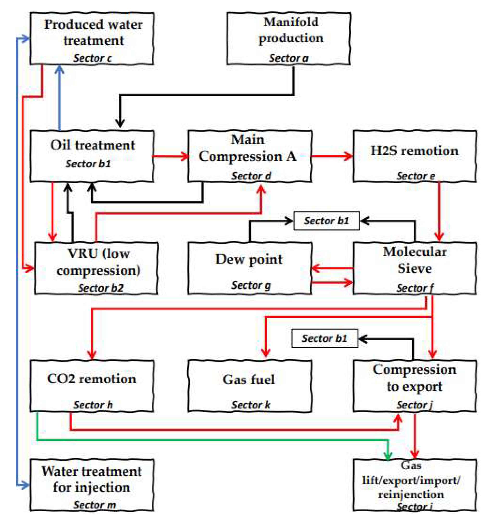
Figure 3.1.
Classical and efficient production process flow block diagram for processing and storage of oil, gas, and produced water in an FPSO. Red is gas, black is oil, blue is water and green is CO2/CO.
Figure 3.1.
Classical and efficient production process flow block diagram for processing and storage of oil, gas, and produced water in an FPSO. Red is gas, black is oil, blue is water and green is CO2/CO.
The real efficiency of an oil platform in time t is given by Eq. 3.4, wherein oil current production is represented by and designates total oil capacity production. The total efficiency during the planning horizon is given by Eq. 3.5.
The present model aims to maximize total oil production, i.e., , while conciliating supply chain demand, reservoir, subsea and topside operational constraints. In the case the fleet crew do not follow a production scheduling, decisions are likely heuristic, which makes it to depend on different mindsets to consolidate production, disregarding potential uncertainties, strategies, and process control challenges, naturally tending to reduce . Not choosing to use the present model means opting to be susceptible to create disorganized decisions, which can lead to a state where, when an uncertainty happens, there can be no time to think about; thus, tending to execute either non-optimal decisions or out of the meta. In practice, this model can be used in parallel to multiple PID controllers, having their setpoints being given by the present model. Conversely, when user wants to trustily operate using the MPC, some of these PID controllers can be disregarded when having their manipulated variables being made part of the present model's decision-making.
3.1. Oil Treatment (Sector b1)
After the topside choke valve(s), the high-pressure three-phase horizontal vessel (Figure 3.1.1) that separates oil (some platforms have a heater treater), water and gas must operate within bounds of capacity (Eq. 3.1.1 and 3.1.2). A platform has horizontal vessels and the total capacity bounds production (API spec 12J) through Eq. 3.1.2. represents oil, water and gas, respectively. Besides, even not using the MPC, if it is wanted to control the impact of the slug flow through scheduling, the model naturally does it if the user provides a practical lower value for the processing gas capacity in the horizontal vessel.
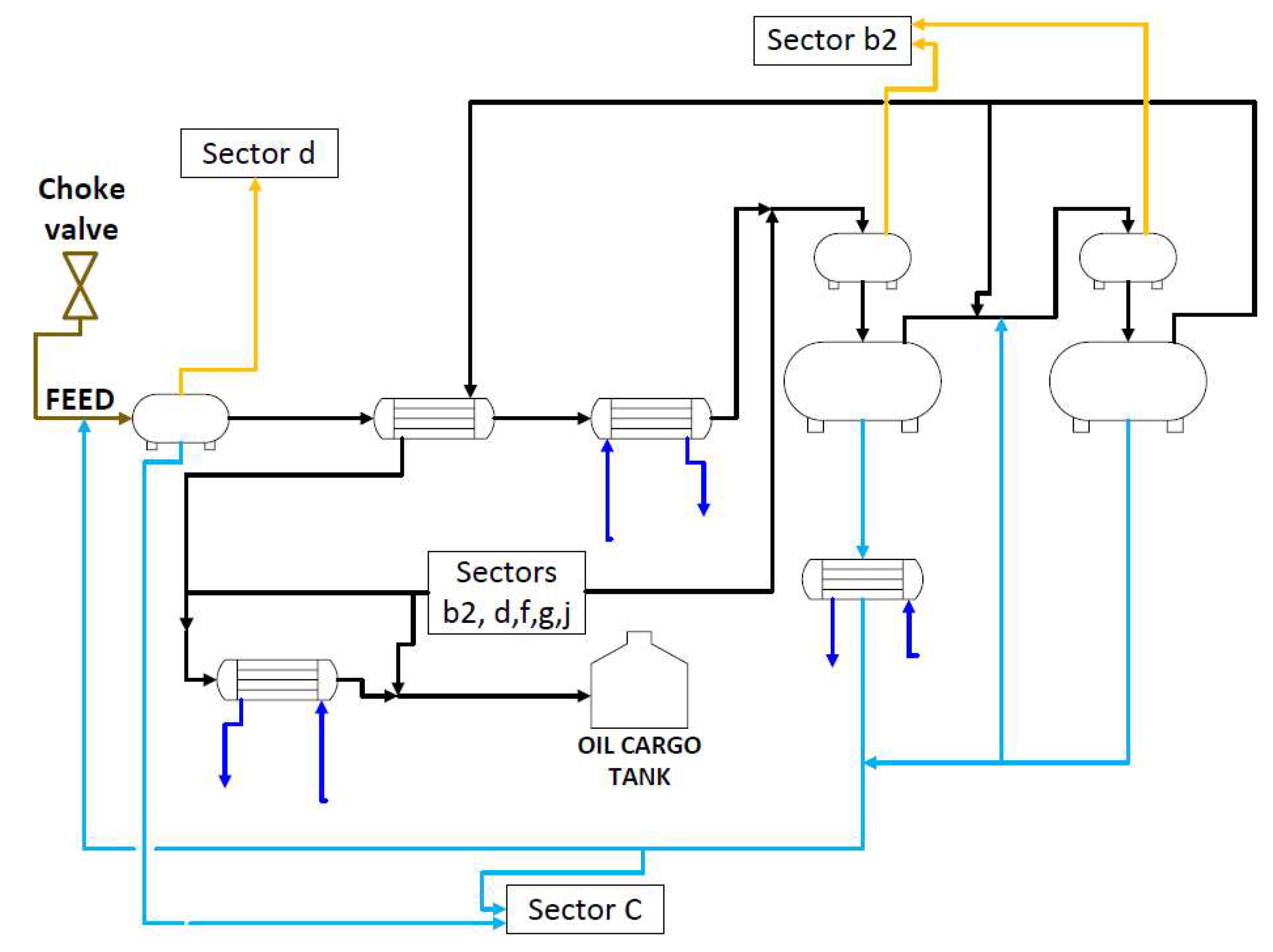
Figure 3.1.1.
Main streams in Sector b1 in a simplified process flow diagram. Feed as brown, oil as black, gas as yellow, utility water as blue and process water as light blue.
Figure 3.1.1.
Main streams in Sector b1 in a simplified process flow diagram. Feed as brown, oil as black, gas as yellow, utility water as blue and process water as light blue.
It is important to note that the capacities , , and , as well as the chemical compositions, are uncertainties that vary with respect to time. There are two approaches to cope with these uncertainties: the first one is considering that in a short-term planning horizon one should always specify them based on measured current plant conditions or estimate; the second one is more general and can be used even to long-term run that is considering that that capacities' upper bound are a linear function of the running production time. For modeling purposes, and declines with time, while increases. The same happens with the compositions. will not decline with the passing time if all the gas is reinjected in the reservoir. These functions can be nonlinear and smooth, but as the reservoir’s exploitable mass is gigantic and way bigger than the amount of oil exploited during a chosen planning horizon, the linear approach is realistic, and also because oil is instilled produced. In this second case, one can establish a conditional time for the long-term planning to start changing , , and values if desired.
Adding water by reinjection in the wells () will retard the reservoir pressure maturation. Due to , , and , the reservoir pressure can increase instead of diminishing in the point it is being extracted oil, and the model can track this revitalization.
The user may define properly capacities and . is the mass processing capacity that can still be completed to occupy the entire rated design of the vessel. If one exactly specifies , or do not specify a slack space or did not when sizing the equipment, is typically zero. The oil composition in the feed stream of the three-phase vessel relates to the choke valve flow (Eq. 3.1.3). Therefore, Eq. 3.1.4 and Eq. 3.1.5 must not be included in the present optimization because of the degree of freedom. Generally, at least 95% () of the gas is separated in the vessel. Eq. 3.1.1, 3.1.2 and 3.1.6 substitutes using Eq. 3.1.4 or Eq. 3.1.5 for respecting the degree of freedom.
Eq. 3.1.1 and Eq. 3.1.2 are important not only using any objective function, but because if one wants to maximize the overall mass flow entering the platform without knowing the mass compositions but knowing the lifespan case flow, Eq. 3.1.1 and Eq. 3.1.2 can suppress using Eq. 3.1.3 – 3.1.5. Note that it would be the same modeling approach with just a different objective, maximizing oil, gas and water at the same time subject to all constraints, including capacity limitations.
Note that , , and are composition parameters and they must be inputs to the model for not handling nonlinear terms, unless the user wants to directly solve a capacity problem (for indirectly solving convex capacity design see Barbosa Filho and da Silva Neiro, 2022). is the percentage of gas that is completely separated in the horizontal vessel. Part of the gas coming in the oil platform () is still within the oil when it is separated in the horizontal vessel, and part of this gas is liberated through expansion in upcoming flash vessels. is the majority part of the gas liberated within the oil carrying remaining gas. Eq. 3.1.7 relates the first flashing and second flashing of the oil to free gas together with the mass of gas being retrieved in the sector c within the water.
is the mass of gas that leaves sector c after being free of water and goes to sector d through sector b2. Regarding the operation of the second flash to free gas from the oil, it has only valves before this equipment, therefore no utilities are consumed. The mass of the expanded gas in the second oil flash (Eq. 3.1.9) must be equal to a specified percentage amount that first expansion (Eq. 3.1.8) could not carry out. While the rest of the gas to close the material balance left in sector c (Eq. 3.1.11). and are generally equal to 0.02 in an interval of ]0,1[.
(Eq. 3.1.10) is the mass flow of gas that goes to sector b2 after flashing in sector b1 and after the main horizontal vessel stage. Regarding the electrostatic treater application (electrostatic desalting/coalescer) to the oil and water for water separation, the first field being applied must consume more or equal energy than the second one (Eq. 3.1.12 to 3.1.14). The electricity must be used to ensure the total separation of water and gas in the electrostatic vessels. After the electrostatic vessels, there is commonly a minority of water still in the oil, so there is also the need for historical data lower bound in the second one.
and behaviors can be linearly or nonlinearly related to the amount of mass flow entering the electrostatic fields or can be manipulated and controlled as a setpoint in the programmable logic controller (PLC) or distributed control system (DCS). Eq. 3.1.15 and 3.1.16 demonstrate the options.
Some oil platforms have a heater treater in the three-phase vessel using steam () or hot liquid water to improve gas separation. is the minimal amount (economic) of water steam or converted latent heat that would be necessary to flash a certain amount of gas in the first flash before the free-water electrostatic vessel. Note that if too much heat is given to the first heat exchanger or to a heater treater, the light oil or gas will be flashed either out of the desired specifications or will consume excess steam, therefore it must be bounded. Then the economic constraint for the utilization of the first flash is given by Eq. 3.1.17.
has unit of kilogram of water per kilogram of gas. The LHS has unit of mass of water steam, as well as the RHS. The bigger the temperature difference of heat exchange, the lesser is the utility waste, i.e., less flow needed, and more economical is the process. depends on the influence of each plant, and thus, data can be used to determine RVG values through artificial neural networks or regression. If one wants to model instead of specifying, this could be done through mathematically modeling the boiler system or even with the assistance of a process simulator software. However, empirical parameters such as global heat coefficient should be estimated, therefore the use of data science avoid these steps. In section 3.10, a strategy to calculate the equivalent heat exchanged if hot water were used instead of steam is disclosed.
High-pressurized gases are connected to the flare to grant process safety (Eq. 3.1.18 and 3.1.19). can be a binary variable or parameter, 1 if the high-pressure connections to the flare are on, otherwise 0.
Eq. 3.1.20 and 3.1.21 ensure process safety according to the current production technology available in the planning platform, a minimal specified quantity of wasted gas must be set to provide the flare to stay on to enable a safe operation when necessary (Eq. 3.1.20).
Eq. 3.1.20 precludes that is not zero for any t, and the constraint Eq. 3.1.21 forces that is equal to one and precludes to assume low values, respecting the flare's objective, and limiting to desired values.
Eq. 3.1.22 is the main mass balance of sector b1, complying that each element in the objective function must stay within tractable bounds (Eq. 3.1.23). is what is stored of oil at the end of time t. is the initial inventory of the first element of the set of time . The present model means that after each 5 days of operation, the stored oil and gas are offloaded the next day. So, e.g., on the 6th day, production starts with an inventory having oil equal to . If the planning for offloading ships has less than 6 days, there is no offloading to be accounted for. Defining homogeneous offloading days and delivery is wise because in that way the future can be predicted, otherwise, it is heterogeneous and means that production is not organized enough so the future can be predicted (would make epistemic uncertainties more dangerous). It is also possible to integrate supply chain decision-making in this step of the model for better deciding optimal offloading day, i.e., it can be made manually specifying or using some stochasticity as Barbosa Filho and da Silva Neiro (2022). Offloading can make inventory reset to any setpoint chosen by the user. The offloading planning horizon can be specified other than 5 days. The longer is the interval days between offloading the less trips will be needed and more optimized (filling ships to maximum) will be the supply chain delivery, for oil or gas, because delivery is monotonic, but it is not smart to be greed and put it close to maximum storage capacity for safety purposes. Typically, an FPSO can store production to 9 to 11 times daily plateau production.
The way Eq. 3.1.22 is written serves any planning horizon. The model can also perform planned halts for total cleaning and maintenance, etc., needing just to put a rule stipulating that, at the day it happens, the impact variable must be zero, e.g., if it is wanted to halt the production to construction and assemble or to make a complete maintenance. The offloading day is an important decider to schedule supply chain but is not crucial to determine operational setpoints to the subsea and topside if the inventories are between feasible bounds, i.e., even if in practice offloading occur in different days, setpoints can still be maintained if controlling the inventory.
Without planning, the oil is usually stochastically transferred to tanker ships but recommended when it reaches not more than 80 to 90% of its total storage capacity, contributing to uncertainty and to more costs owing to more travel. The present model prevents the necessity to make heuristic decisions. and is the capacity of the tank within the planning horizon. All the oil that is coming to sector b1 is the oil that comes from the manifold and the oil that comes from all the condensed gas and retrieved oil from all the other sectors. This is resumed by the mass balance (Eq. 3.1.24). In this model, , , and are specified as parameters or variables within practical doable bounds as a measure of controllability as ongoing production measures are known within the plant. Eq. 3.1.25 grants practical feasibility and degrees of freedom. Note that the capacity is a time-dependent variable since oil sludge occupies space in the tank. If an offloading time is specified such that this space is not enough to fully occupy the total storing capacity together with the oil stored itself, then oil sludge is never a problem since the cleaning can also be performed on the offloading day.
is the mass flow of heavy gases from sector j that returns to sector d to become gas and condensate again in the compressors and vessels of sector d. The mass balance of the gas regarding sector b1 is Eq. 3.1.26. is the mass flow of gas that goes to sector d counting what is separated in the main horizontal vessel and what must come by recycle entering in the sector d. The mass balance for the utility water used in sector b1 is given by Eq. 3.1.27. Dilution water is added before the second electrostatic field, in which this dilution water can be generally heated by a heat exchanger using hot water or steam to provide more dispersion and separation when at the second electrostatic field.
is what is recycled for safety operation if needed, but in normal operation it should be null. is the water mass flow that is used as utility in sector b1 to cool the oil stream that is being stored. To predict uncertainty, slack production or to set the minimum amount to maintain the flares of sector b1 and b2 burning to a maximum value , the constraint Eq. 3.1.28 must be applied:
Apart from the current decision-making, it is optional to put a constraint that limits production due to supply chain demand (Eq. 3.1.29). This feature comes to be interesting when market demand usually has a dynamic, which will influence the variable values setpoint generated for the controlling throughout the platform and the subsea. This reconciliation is granted when inserting Eq. 3.1.29. and are the minimum and maximum bounds for the oil supply chain demand, respectively. Further in section 3.7 (sector j), is the amount of the stored gas at the day in which offloading is occurring, and with the same analogy as Eq. 3.1.29, the gas supply chain can also be bounded.
3.2. Produced Water Treatment (Sector c)
In this sector c (Figure 3.2.1) the water still has salt, oil, and gas, and needs to be pretreated to minimize pollution and to mitigate corrosion and incrustation before being sent to the rest of the process as utilities. The water enters sector c with approximately 1000 ppm of oil and must leave at least with 15 ppm or less. Note that this standard can change according to local exigences and company, e.g., as per date, IBAMA's TOG (Total Oil and Grease) exigence is 29 ppm, while MARPOL's is 15 ppm. Once the water feeds sector c, it still has hydrocarbon gas wherein is separated in the horizontal vessel of sector c and sent to sector b2. The water getting through the de-oiling hydrocyclones before flotation must lead to a downstream with less than 10 ppm of oil each. Sand is removed in these steps if existing. regards the number of cyclones splitting the main stream of water entering in the parallel cyclones in time t for a certain incoming mass flow to the platform. Without recycling, this is resumed by Eq. 3.2.1 and if recycling is considered from other sectors, Eq. 3.2.2 is used instead.
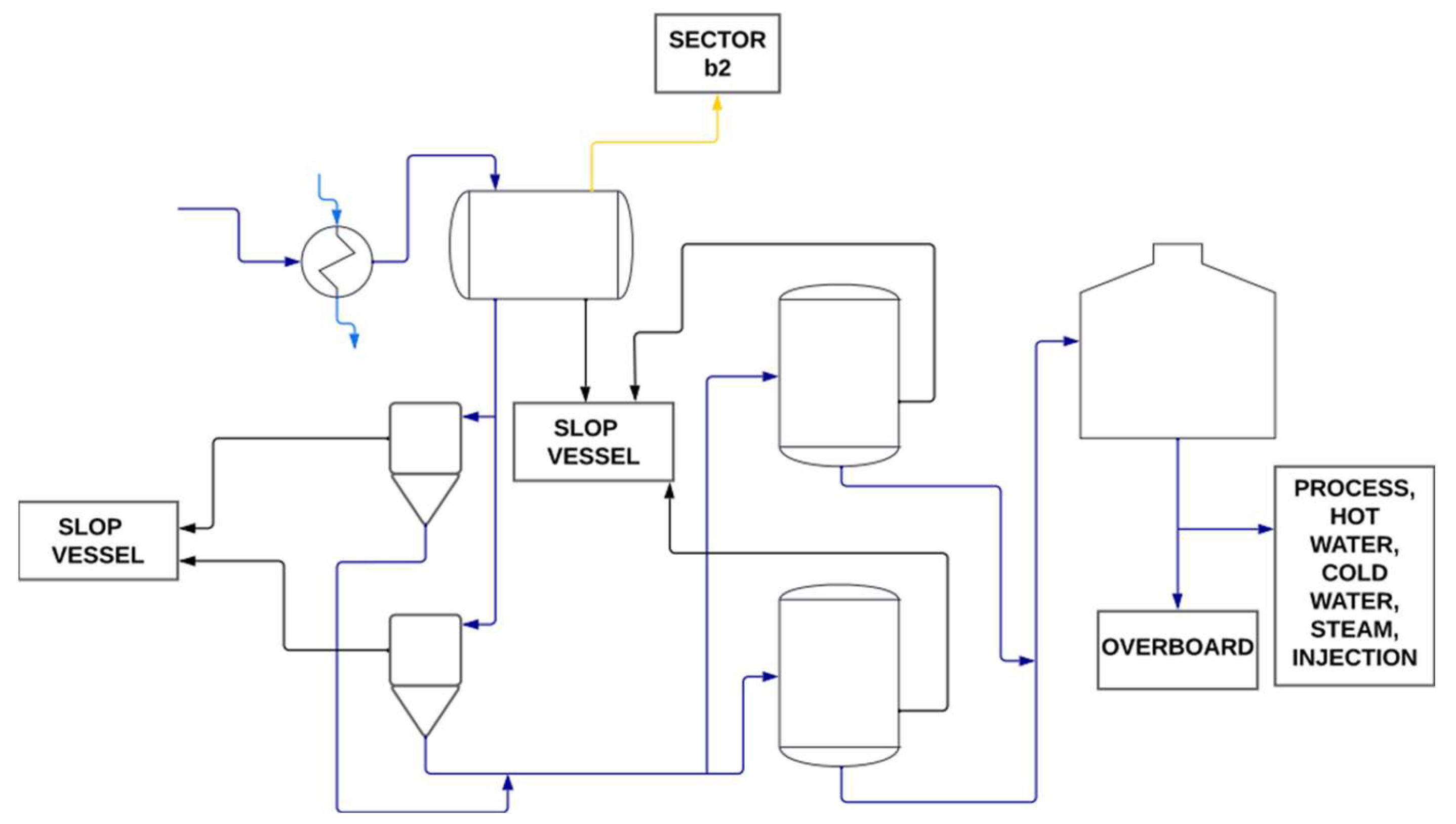
Figure 3.2.1.
Main streams in Sector c in a simplified process flow diagram. Oil as black, gas as yellow, utility water as light blue and process water as blue.
Figure 3.2.1.
Main streams in Sector c in a simplified process flow diagram. Oil as black, gas as yellow, utility water as light blue and process water as blue.
is the minimal amount of water that must enter in each cyclone to remove the oil and remain with less than 10 ppm of oil. The amount of liquid water entering sector c must be greater than the steam used in the platform (Eq. 3.2.3). The following constraint (Eq. 3.2.4) regards sustainability and economy. For an intelligent decision-making regarding these two important topics, the flare-gas recovery system must work providing security and minimal pollution of H2S, CO, CO2, and carbon emission (Eq. 3.2.4).
is the economic mass flow that provides the maximal economic waste of gas. can be a binary variable or parameter, 1 if the low-pressure connections to the flare are on, 0 otherwise. is the amount of gas burned in the LP flare as a decision variable. The constraints below (Eq. 3.2.5 and Eq. 3.2.6) do the same as an analogy to of those constraints of sector b1(Eq. 3.1.20 and Eq. 3.1.21).
is the amount of water used as a utility in the platform. is a parameter that refers to the amount of water injected into the well to increase oil production if the platform complies with this technique and the well is mature. To create a safe and smart operation, the gas going to the flare system to keep it on does not come from PSVs but from a low-pressure stream of gas. The idea of optimization is to not account for the use of relief valves, but indeed avoid the use of them. To do so, the previous equations guarantee that the main compression system (sector d) has its flare connections off when also setting and , so this will keep high-pressure systems connections off to increase operation safety.
3.3. Vapor Recovery Unit (Sector b2)
Sector b2 (low compression, Figure 3.3.1) is responsible for liquid hydrocarbon recovery. It also reinjects the low-pressure gas resulting from the separation from the water sector (sector c), in the high-pressure main gas process (sector d). Heavy gases are condensed in flash vessels, so the further liquid output depends on the amount of electricity used in the compressors. The following constraint (Eq. 3.3.1 or Eq. 3.3.2) is versatile, meaning the math signal can be switched according to the platform's needs.
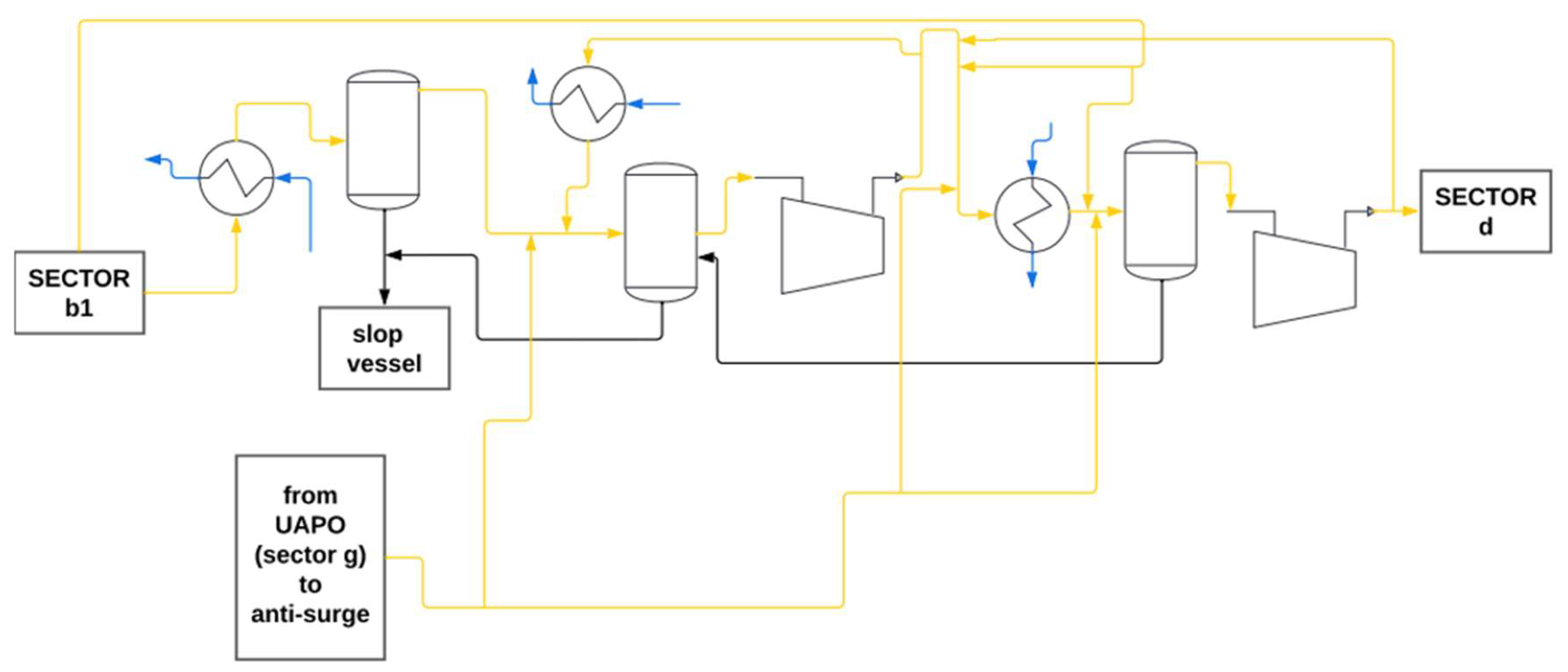
Figure 3.3.1.
Main streams in Sector b2 in a simplified process flow diagram. Oil as black, gas as yellow, utility water as blue.
Figure 3.3.1.
Main streams in Sector b2 in a simplified process flow diagram. Oil as black, gas as yellow, utility water as blue.
is the percentage of gas that do not condensate, whereas is the percentage that do condensate. Moreover, if and are variables, then the following constraint (Eq. 3.3.3) must be included in the model, but if they are parameters, simply consider it before specifying them.
Cold water is used to reduce the gas stream temperature to provide condensation also with the compressor actuation. This utility used before each of the flash vessels must obey only one of the following four hierarchies (Eq. 3.3.4 - 3.3.7). Utility water used in condensation must respect the limits of availability (Eq. 3.3.8).
This model is versatile, so different settings can be provided, for the platform may have different needs. These different settings can be tested on different optimizations to perform a selection of the best one to design the daily operation. is the upper bound for cold water being provided to sector b2. Using data with mechanistic laws is a good strategy since actual patterns can be connected to the model and bound utilities to tractability. The present model provides this possibility, as shown again (Eq. 3.3.9 - 3.3.11). For granting condensation the amount of cold water used must be greater than minimal necessity (Eq. 3.3.9).
With , , being design parameters. Moreover, if , and are variables then the following constraints (Eq. 3.3.12 and 3.3.13) must be included in the model, but if they are parameters, simply consider bounds before specifying them. is the percentage of condensed gas in the first flash. is the percentage of condensed gas in the second flash. is the percentage of condensed gas in the third flash. For an excellent process design, must be greater than the sum of with . If one wants to make a conceptual design, let any of , , , , be variables.
The amount of water available for the sector b2 must be equal to or greater than the amount of water used to condensate the gas (Eq. 3.3.14). can be a decision variable, a specified parameter, or an uncertainty.
For an efficient system, the compressors' electricity in sector b2 must be smartly limited (Eq. 3.3.15). Electricity must be greater than the minimal amount needed to condensate the maximum economical amount of gas into oil, and must be less than the maximum energy available to sector b2. The energy used in the compressors is the sum of energy used on each one (Eq. 3.3.16).
The following constraints (Eq. 3.3.17 and 3.3.18) must be suppressed if and are setpoints/parameters specified to this model. The first condenser generally does not have a compressor before it. The only compressor important for the gas condensation is the first, since this sector's second (last) compressor is placed after the third flash vessel. As there is gas to be condensed after the first compressor (second flash), the energy consumed in the first compressor must be greater than in the second one (Eq. 3.3.17). Usually, depending on the hydrocarbon composition of the gas, if there are fewer heavy hydrocarbons, then the electricity in the second compressor can be greater than the one used in the first compressor to ensure further condensation. The second compressor is responsible for reinjection in the main high-pressure gas system separation. Therefore, Eq. 3.3.17 becomes Eq. 3.3.18.
is generally controlled in a setpoint value being a parameter in the model because stability is needed in the entry recycle stream of sector d. Instead of directly giving it as a setpoint to the present model, it could be calculated by a nonlinear model prior to optimization. In this last case, the needed power to give the needed pressure to the outlet gas stream would be calculated. All compressors in the set of compressors have operational capacities; therefore, they must be bounded (Eq. 3.3.19).
The condensed gas into oil, after the compressor, also must be bounded since the compressor must be smart in energy consumption. Therefore, the mass of condensed gas can only be related to the first compressor and the flash vessels. A limit exists in which wasting more electricity is not economically profitable anymore when condensing gases — too much waste will not generate oil to provide profit. Eq. 3.3.20 resumes this.
One must choose one of the following three constraints dependent on data, and they are essential for the planning (Eq. 3.3.21-3.3.23). Any inaccurate information or even misinformation could lead to undesired decision-making in the feasible solution. Eq. 3.3.21 - 3.3.23 regards calculation of which is thermodynamically found through nonlinear modeling but can be linearly approximated and found through regression or can be a setpoint. Note that in the industry typical operating points are well defined, e.g., 70 to 75% efficiency. Then, near this region, compressor regression can be linearly controlled in the practical, accepting linear modeling.
This second form (Eq. 3.3.22) is more relaxed, and if one wants to know how much power needs to be used in the first compressor by choosing this constraint, one needs to make a simple substitution out of optimization in this function to determine the value. Eq. 3.3.21 and Eq. 3.3.22 need data to be created by a regression, and both can be used together in the model. Note that can be set equal to a specified parameter in case the planner can set to operate with this specification in the plant through the process control of this manipulated variable. In other words, is the setpoint of the system (Eq. 3.3.23). In this case, the model does not calculate the value of the electricity used in this first compressor, but as it is a setpoint, an offline system can easily calculate it after the variation of the frequency inverter acting as the control actuator.
Historical data regression provides a function of electricity for the economical maximum value for the oil generated by gas condensation on each compressor that has a further flash condensing oil. In this case, we assume, as classical production, that there is one flash. The value of is the upper bound in which trespassing will start to decrease either profit or the platform energy efficiency. Data science is an important friend of this model. If no data is available on the platform, then thermodynamics can be used to calculate the energy necessary to achieve a PVT state, leading to an economical process. These calculated values are the upper and lower bounds to constraints regarding electricity. The following material balances tie sector b2 to the model (Eq. 3.3.24 – 3.3.30).
Sector b2 has only one compressor promoting condensation to a vessel, and it is located after the first two condensers on the series. Generally, there is only one condenser after the compressor of sector b2. These condensers are flash vessels and work without wasting utilities. Note that if the user states that , then must be a positive variable in the model, and also should add a constraint stating that the sum of , and are equal to one, while and remains as being parameters. This way the model will search for the upper bound of aiming to maximize oil production. If is a parameter, one need to state as being a controlled setpoint (parameter) instead of calculating it and note that this setpoint value must be reliable to value. There is an upper bound to that forward from that will not condensate any more gas than the percentage , so specifying more power than this point is practically feasible (till anti-surge control can support it) but not economical.
3.4. Main Compression (Sector d)
Before sector d, the oil can be ensured to be removed out of H2S in a nitrogen stripping system or other technique to store and transport it eliminating the risk of explosion to tolerance. In sector d, H2S can be removed from the gas stream between the stage when the gas is first condensed in the first vessel and the stage when the gas is sent to the main compressor system. Once the H2S has been stripped/removed from the crude oil/gas, it is usually flared emitting SOx to the atmosphere. Flaring will also be a practice of burning gas that is uneconomical to collect. For the gas having H2S, it is usually removed by the reduction to the sulfide ion and H2 at the cathode. These systems work without prejudice to the oil and main gas materials, therefore H2S should not be considered in the mass balance of the present model.
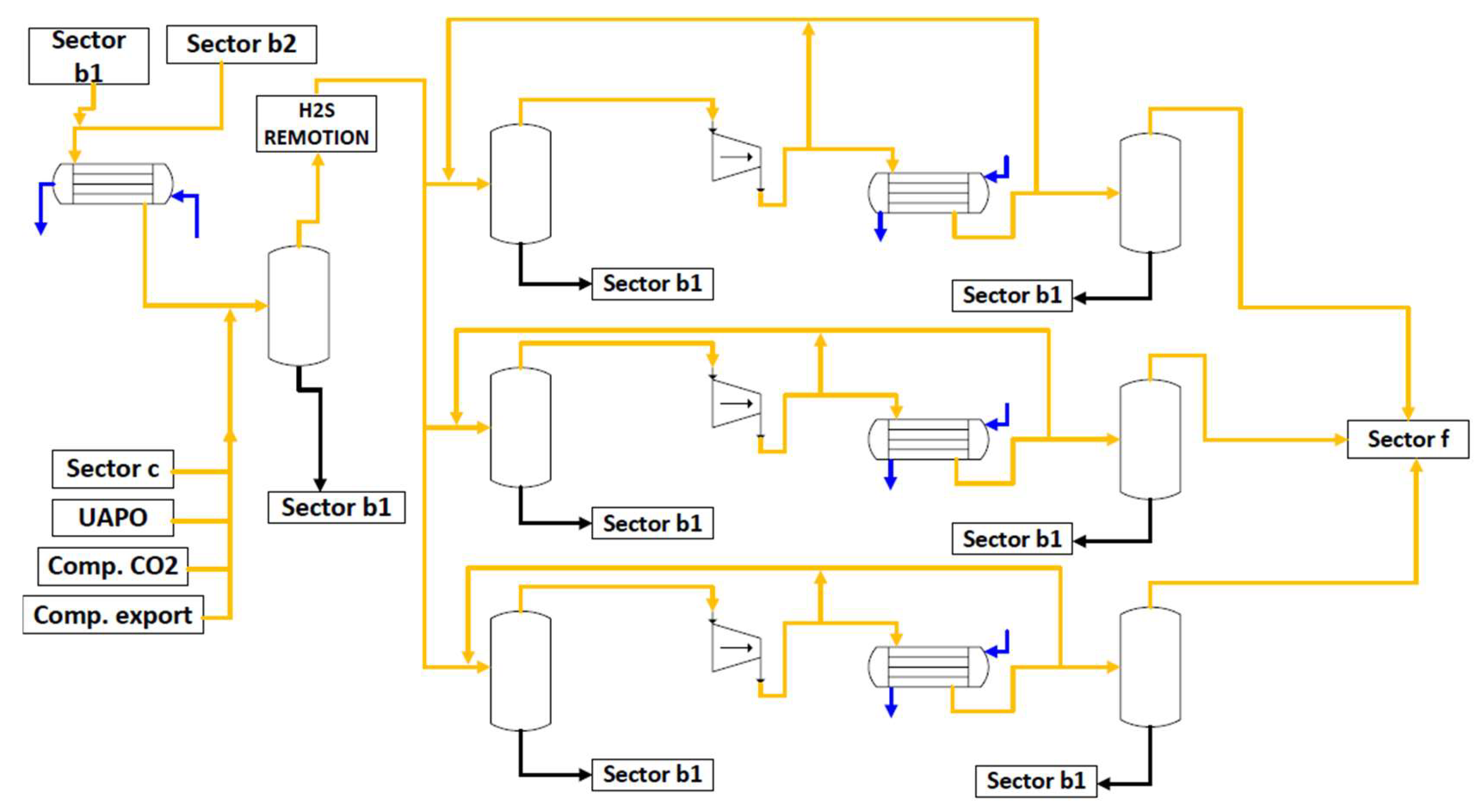
Figure 3.4.1.
Main streams of Sector d in a simplified process flow diagram. Oil as black, gas as yellow, utility water as blue.
Figure 3.4.1.
Main streams of Sector d in a simplified process flow diagram. Oil as black, gas as yellow, utility water as blue.
This sector d must have the gas having almost no water since hydrates could be further formed in the pipeline/P&I and would clog production and piping systems. Most of the water is removed in sector b1. The sector f is responsible for eliminating the water. The main pipeline that must not be clogged is the pipeline of gas reinjection serving as gas lift for assisting the oil to be lifted with high pressure. Clogging this pipeline is hard to clean and could halt operation. As the gas in the sector d has almost zero humidity but still has, the further objective is to create a dew point for the mixture of these hydrocarbon gases to avoid hydrate formation and preclude clogging the systems when reinjecting the gas or exporting in the 4 ºC subsea pipeline. Based on this argument the mass flow of sector d must be bound as in Eq. 3.4.1 and 3.4.2.
The parameter is the total amount of produced H2S separated in the H2S remotion sector. Based on the availability of energy in the platform, process equipment, well compositions, and chemicals used, a versatile constraint can be included in the planning (Eq. 3.4.3 and 3.4.4). Either the sector d is responsible to condense more gas into oil than the amount of retrieved gas or the contrary.
is the retrieved gas from all the purifications of water and oil, and is not all the gas that enters sector d. It is the gas that joins the main gas separated in sector b1 and that comes from the previous purification sectors. The mass of gas retrieved from purification, and that is used in the sector d, is linked in the following mass balance for the sectors b1, b2, c and d (Eq. 3.4.5).
is the amount of mass of gas that enters in the dew point adjusting unit (sector g) and is condensed to oil (), having its value corresponding to a percentage amount of heavy gases returning from the sector g. is the percentage of heavy gases that are condensed in sector g and is returned to the main stream as in gas phase to be condensed again to be sent to sector b1 to be finally stored as oil. can be an uncertainty for this model, and it is smartly specified through either a statistical pretreatment of historical data (Eq. 3.4.6) or by a percentage estimation of (Eq. 3.4.7).
For process security purposes, sector d also has the possibility to recycle through bypasses part of the hydrocarbon gases from sector j, responsible for gas combustion, exportation, and membrane operations. refers to part of , and refers to part of . refers to part of . Generally, their valves remain closed, and for planning and scheduling purposes, , , and values are set to zero — no deviation in the planning, but one may decide whether the values are for scheduling or analysis/study.
The amount of condensed oil from the main gas joined with the retrieved gas is determined through the electricity specification in the compressors. This sector usually has parallel compressors and flash vessel systems, so the main stream is split through a collecting piping. The operation concerning compressors must obey the constraint given by Eq. 3.4.8.
To understand the importance of and what it is, one must know the answer for the following question: what is the percentage that is the maximum limit for the mass flow of condensed oil (from the gas) in this sector d for making the process profitable? can have two meanings by its specification, either it is the minimal historical value of power in which sector d operates, or it is the minimal electricity/energy required to condense a certain optimal profitable amount of condensed oil to make this happens. Generally is determined before the optimization by specification through data visualization or by a sensitivity analysis through a plot versus . Instead of using the constraint above (Eq. 3.4.8), another constraint (Eq. 3.4.9 or Eq. 3.4.10) could be used to map electricity used and gas condensation.
is the amount of oil being extracted because the condensed gas in the first flash must be enough () either to allow the maximum feasible effort in the further compressors without drowning it or to avoid surge. Again, this second form (Eq. 3.4.10) is more relaxed, and if one wants to know how much electricity is to be used in the compressors by choosing one of the two constraints above (Eq. 3.4.9 or 3.4.10), just need to make a simple substitution, out of optimization, in this function to determine the value. Both constraints need the use of data to be created by a regression, and both can be used together in the model. In this case, all the functions should be determined before the optimization is done through regression or other techniques. Note that if this last approach is considered, the function could probably be nonlinear. Instead, the planner can replace either Eq. 3.4.9 or Eq. 3.4.10 by using Eq. 3.4.11 to create a setpoint.
In this case, the setpoint is generally reached and is generally controlled by the compressor and other process variables such as the valve and utilities before the flash. The electricity available for sector d is limited (Eq. 3.4.12). can be either a variable or a parameter for decision-making.
The whole model is versatile, and the decision maker should know what they want. Eq. 3.4.13 is optative and states that the minimal electricity used in the sector d should be greater than the minimal energy required to create a dew point and not let the gas condense at 4ºC.
Water is used as a utility to cool the main gas stream temperature each time before it enters a compressor. is the water mass flow that is used as utility in the sector d (Eq. 3.4.14 and 3.4.15) and is typically calculated and specified prior to making the optimization.
3.5. Gas Dehydration with Molecular Sieves or Glycol Dehydration Unit (Sector f)
Most FPSOs and oil platforms use molecular sieves instead of glycol dehydration, e.g., Petróleo Brasileiro S.A. use it in all pre-salt operated FPSOs and in almost all the others as part of its fleet or under contract. This section describes the modeling for gas dehydration through molecular sieves, but a generalization can be made if the FPSO has a gas dehydration unit/system based on glycol (e.g., triethylene glycol, TEG), which is further discussed. If in the future new technology arrives, then one just needs to adapt. Sector f (Figure 3.5.1) is responsible for almost completely removing the water from the gas — less than 50 ppm of water — but some part of the gas is still condensed in the flash vessels. Sector f is or can be operated in a parallel batch mode having equal systems working together. The mass of gas leaving the main three-phase vessel of sector b1, minus what is converted and removed, must be greater than the amount that is further converted to oil in this sector f (Eq. 3.5.1) to optimize or ensure that the project will operate with this vessel design capacity. Eq. 3.5.2 represents Eq. 3.5.1 in a less relaxed way and can be used instead. Eq. 3.5.3 represents the mass balance of gas for the flare system, with being the amount of mass of gas that leaves from all the sectors through the flares. Eq. 3.5.4 and 3.5.5 do the same as an analogy to of those constraints of sector b1 (Eq. 3.1.20 and 3.1.21). Decision variables of this sector must be bounded as in the practice (Eq. 3.5.6 and 3.5.7). Eq. 3.5.8 can be used instead of Eq. 3.5.7 in case the flashes have the same operational capacity.
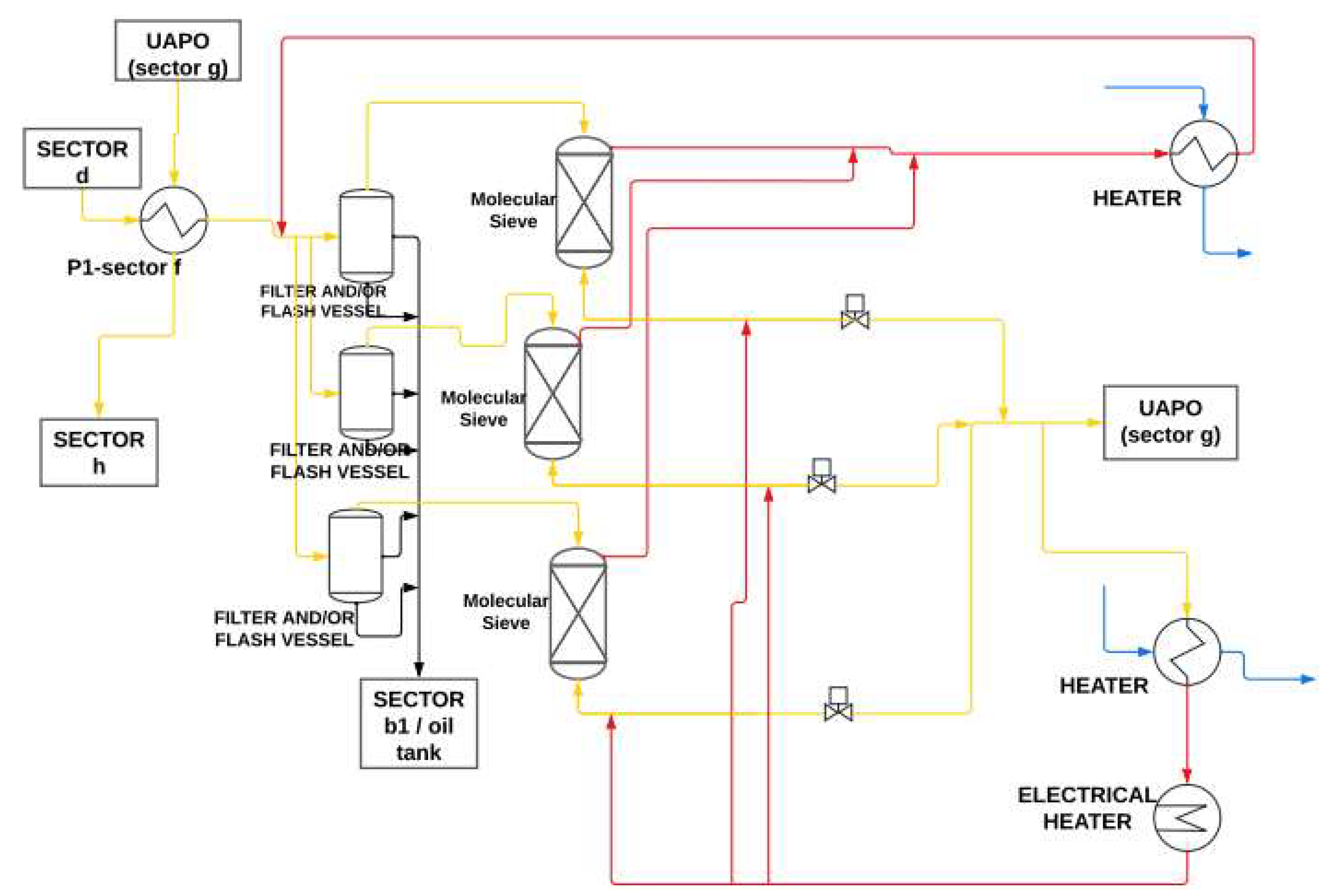
Figure 3.5.1.
Sector f in a simplified process flow diagram. Oil as black, gas as yellow, utility water as blue, retrieved gas as red.
Figure 3.5.1.
Sector f in a simplified process flow diagram. Oil as black, gas as yellow, utility water as blue, retrieved gas as red.
is how much in percentage a flash i of sector f can transform the inlet gas into oil. The mass balance given by Eq. 3.5.9 must be satisfied. In case the flashes have the same operational capacity, Eq. 3.5.10 is used instead of Eq. 3.5.9.
Eq. 3.5.11 forces the practice to let have a typical design lower bound. is a limiting parameter coefficient that validates the constraint and can be used to design these vertical vessels for a process synthesis design (standard value equal to one). Its value must comply with the platform capacity and feasibility. The electricity is also limited to this sector f (Eq. 3.5.12).
A lot of steam or hot water and electricity is used in sector f. In some platforms there are electrical heating systems that are usual for the plant start-up, in which they are turned off when the plant becomes to operate either in steady-state or when there are some problems concerning this heat exchanger system. For typical heuristic operational mistakes/omissions, these electrical heaters are usually turned on to provide productivity. A well-planned production schedule and thermodynamics can eliminate the use of this less-safety electrical system, providing a safer environment against fire. The electrical heater is typically installed operating either on series or parallel to the heat exchangers that use water steam or hot water to heat the dry gas before this electrical heater. Its objective is to heat a part of the dry gas leaving the molecular sieves. The reason that the molecular sieves are operated in parallel is that they get clogged within operational time, making it necessary to clean them through insertion of hot dry gas that is recycled when sieve's operational time limit is reached. Typically, this cleaning and heating period are made through batches of about six hours between time intervals of fourteen to fifteen hours. In continuous operation, the hot gas stream leaving the sieves is cooled by a heat exchanger operating with cooling water that typically has a stream aiming to provide an output gas temperature setpoint of 313 K to not harm the operational 307 K temperature of the molecular sieves. Water can be used to cool the main stream before the molecular sieves but instead it is typically used a cool stream of gas that is recycled. Eq. 3.5.13 represents the mass balance for the utility water.
Water utility is also used to provide flash separation before the molecular sieves. An intelligent decision is to use water close to the amount necessary to perform a flash necessary to maximize the oil condensation. is the latent heat of water steam. Generally, about 10% of this dry gas is recycled inside sector f. Letting as being the percentage of recycled dry gas out of , the constraints that provide thermodynamic efficiency, bounds, electricity and calculation of the utility amount that must be generated/used of steam or hot water to sector f are given by Eq. 3.5.14 – 3.5.24.
is the amount of water that is used as utility in the sector f. is binary, 1 if the electrical heaters are on, 0 otherwise. is the amount of heat given to the dry gas recycle stream by the heat exchangers before the electrical heaters. is the minimal amount of heat required to clean the sieves in an ordinary daily operation without halting the production process. is the amount of water steam available in the whole platform. is the efficiency of the electrical heater on transforming electricity to heat, typically between the interval .
Typically equal to one, is a ratio parameter or variable to specify proportionality of how much must be bigger than . Letting as a variable is more when ones want to develop a conceptual design for basic and detailed engineering. Making it vary as a parameter within a grid search can also be a strategy for conceptualization.
In the practice, if there is no steam available in the plant, one must convert to use the equivalent amount of calculated hot water as stated in the Water Systems' section (section 3.10), or one could use the equivalent amount of heat as machine power increased by the machine efficiency. Even if is 1, will only populate values higher than zero if is zero or smaller than . With the constraints of this sector f, the platform can avoid the problem caused by continuous use of electrical heaters, optimizing energy.
These electrical heaters usually have greater chances of catching fire and are safety issues for the plant, using steam instead of hot water could provide more energy and would avoid these systems. Besides that, steam is more heat conservative because has more thermal energy than hot liquid water, an opportunity to heliothermic systems. In that way, using steam provided by installing a concentrating solar power (CSP) system for thermal energy storage (TES) next to the offshore facility could assist on solving the case problem of the plant start-up depending exclusively on diesel electrical heaters/motors; thus, it would minimize pollution and the use of the marine gasoil (MGO). A steam generation boiler can use many ways to produce thermal energy, and the present model fits any.
For process safety and sustainability, some days of operation can be set to not operate with electrical heaters (Eq. 3.5.20). With this statement, it is possible to do either maintenance at these days or even a checkup of the equipment. Sustainability is also provided with this strategy because it diminishes the risk of creating a dangerous setup for fire avoiding overload, for once a platform is on fire, either piping or instrumentation could start oil or gas leak.
is the set containing the elements of time (generally days) in which the electrical heaters must be off. Eq. 3.5.21 – 3.5.23 states that the part of the available electricity, for this sector, that is not used as electricity, can be used to generate thermal energy or to be left over as more electricity available to be used and set bounds for the steam. An electrical heater is preferred than a fired heater or steam heater when it is wanted to avoid emission problems if there is no excess of steam or hot water available.
If there is historically an excess of steam in the platform (), part or all of it can be used in sector f for heat purposes. In case is higher than zero and energy is available after using the electrical heater, if it is the case, then Eq. 3.5.22 and Eq. 3.5.23 will be activated in the active convex region for more energetic efficiency. In case it is not wanted, then just replace Eq. 3.5.22 and Eq. 3.5.23 by Eq. 3.5.24 to set bounds for the steam as a tighter model.
is the left-over electricity of what is to be available to the sector f. The variable is the amount of steam that can be generated with the left-over electricity of sector f. The idea is to optimize the entire platform and push it to generate the maximum possible energy in the turbogenerators. The slack of energy not used in the production could be used to generate slack steam providing new possibilities to production strategies together with renewable energies.
Note that in the case that the dehydration is made through a glycol unit, it has typically at least a glycol contactor, a flash separator, a still column with a reboiler for water remotion (can use steam or fuel gas as utility), and pumps. One must know that the variables that are global within sector f will still exist, and the variables that are not participating in the process must be removed and substituted by others. For example, in a glycol dehydration unit only the Eq. 3.5.14, 3.5.15, 3.5.16, 3.5.17, 3.5.19, 3.5.20, 3.5.21, 3.5.22, 3.5.23 and 3.5.24 must be removed, and if the reboiler uses steam then Eq. 3.5.25 must be added to the model to make as a function of or must be specified, but if using fuel gas instead the amount must be specified and subtracted in Eq. 3.7.13. is the heat amount needed to regenerate the glycol.
Note that the model can be also applicable to the case that the plant has both units, gas dehydration through molecular sieves, and glycol dehydration unit for LNG. In this case, the glycol dehydration unit should be extra appended.
3.6. Dew Point Adjustment (Sector g)
Heavy hydrocarbon gases from the sector f being condensed are mostly C9 and C8, while heavy hydrocarbon gases like C5, C6 and C7 are still present in the sector g. It is an important sector needed to assist in condensing all remaining heavy hydrocarbon gases that would clog the subsea pipeline. Some could form hydrates in a temperature nearly to or less than 4ºC once in subsea. It is a recycling system inside the sector f that uses a Joule-Thompson control valve after an integrated heat exchanger connected to the flash vessel. The objective is to attain the dew point of all remaining heavy hydrocarbon gases. The cold stream is the oil itself condensed in the flash vessel and the hot stream is the feeding gas still with heavy hydrocarbon gases. Sector g (Figure 3.6.1) is a sector inside sector f (Eq. 3.6.1). Light hydrocarbon gases are not affected in this process. Note that generally, the efficiency of this process is not 100% perfect, i.e., that might have C5+ going to the onshore. Eq. 3.4.6 and Eq. 3.4.7 are derived from the sector g.
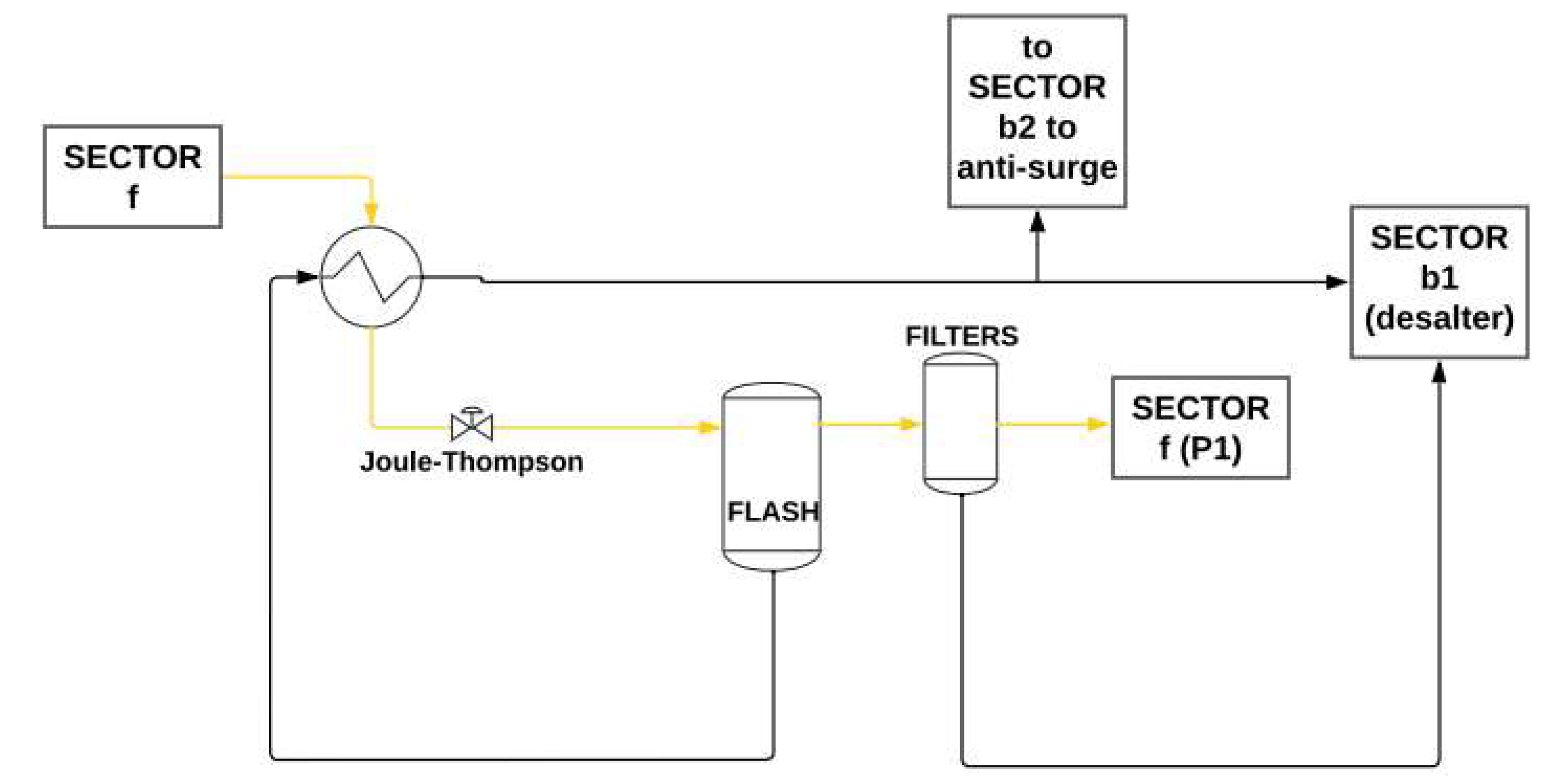
Figure 3.6.1.
Main streams of Sector g in a simplified process flow diagram. Oil as black, gas as yellow.
Figure 3.6.1.
Main streams of Sector g in a simplified process flow diagram. Oil as black, gas as yellow.
3.7. Compression to Export (Sector j)
Sector j (Figure 3.7.1) is the node of sectors f, i, h, and k; therefore, equations from sectors i, h and k can be majority inserted as being mathematically only in the sector j. Sector j is the responsible to compress the gases to export to different options: reinjection (gas lift), energy production, exportation, and storage. Sector j receives the main gas coming from the molecular sieves. Whenever gas is polytropic compressed in this sector, it must be cooled in heat exchangers using an amount of utility water (Eq. 3.7.1 – 3.7.3).
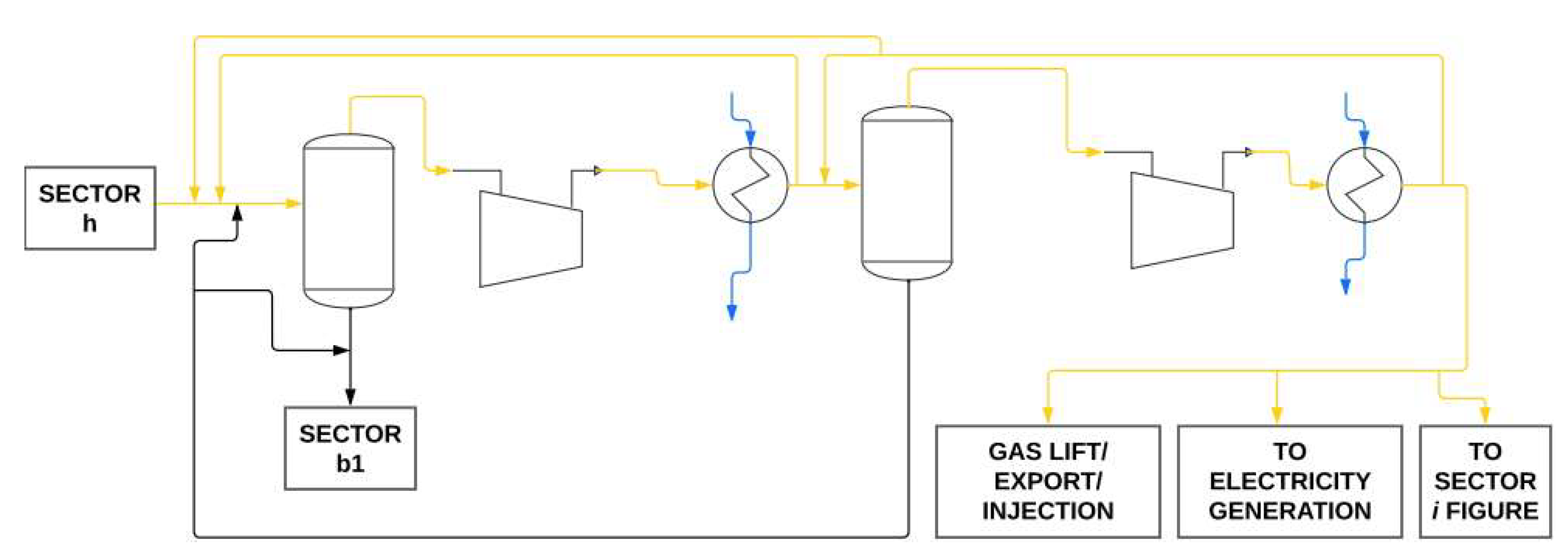
Figure 3.7.1.
Main streams of Sector j in a simplified process flow diagram. Oil as black, gas as yellow, utility water as blue.
Figure 3.7.1.
Main streams of Sector j in a simplified process flow diagram. Oil as black, gas as yellow, utility water as blue.
is the energy used in the first compressor or stage to attain the pressure necessary to condense all the remaining heavy gases when submitted to the condenser. In compressors cannot exist liquid phase, otherwise the equipment would trip or break, then is the energy/power used in the first compressor that would be the limit to attain the pressure and temperature thermodynamically necessary to attain condensation of the gas. One should specify a value close to this limit. The second compressor of sector j has the main objective (Eq. 3.7.4 and 3.7.5) to make the gas achieve the pressure of exportation, gas lift or storage. is the minimal amount of energy used in the second compressor or stage to grant this minimal required pressure.
Pressure depends upon the well(s) and generally the geologist reports the pressure value. is the energy used in the second compressor that would attain the pressure and temperature thermodynamically necessary to achieve condensation of the gas. Note that if the previous specifications grant that there will be no more possible condensing gases at this second stage, then this upper bound can be ignored. Eq. 3.7.6 is optative since it generally does not have a flash condenser right after the second compressor. If there is a flash condenser after the second compressor, then Eq. 3.7.6 must be activated. Eq. 3.7.7. represents the fact that part of the remaining heavy gases contained in condenses to oil and is returned to the sector d.
is the percentage of heavy gases contained in that condenses to oil and is returned to the sector d to then become gas and condensate again in the compressors of sector d. Note that must intrinsic comply with value in the real practice. Just as sectors b2 and d, a function could be provided to correlates and , but this model create the plan to comply with the real practice, i.e., as the oil provided by condensing gas in the sector j is way less than in the sectors b2 and d, a setpoint constraint like Eq. 3.7.7 is better representative, since frequency inverters or control valves are typically available. The mass balances should be satisfied and bounded (Eq. 3.7.8 – 3.7.12). is the mass of gas that goes out from the platform to the flare in all sectors before sector f.
Note that, to use Eq. 3.7.12, the relation must be satisfied as well. is an integer parameter, equal to 1 if the platform must export part of the produced gas through a pipeline or 0 if not. The mode of operation is a parameter that must be 0 if the platform does not generate steam as utility by burning production gas and must be 1 otherwise. is the amount of CO2/CO gas liberated by the burned gas used to generate steam that is being used as utility along the platform, as well as part of it can be used to provide gas lift. The mode of operation is a parameter that must be 0 if the platform does not operate inserting post-burning CO2/CO of the electricity system to reinject to the wells and must be 1 otherwise — a sustainable decision-making.
is the amount of steam that is inserted into the well to provide gas lift or into the subsea rising systems, and it can be either a parameter or a variable. refers to the total mass of gases and steam that is bypassed to the well to provide gas lift. Part of the composition is due to CO2, separated through the membranes, and the rest are hydrocarbon gases. Generally, is either a specified parameter input or a variable calculated by this model as an available slack for production. is the mass flow of hydrocarbon gases that is being injected to the well. can be reinjected or not, it depends on the platform technology; positive integer, if it is bypassed to the compression-to-export sector ( instead of going to the flare, negative otherwise (. In practice, is either directly specified or determined by a fixed constraint and should exist for security purpose and to slack the operation when needed. can be reinjected or not, it depends on the platform technology and if the well is mature; positive, if it is bypassed to the well (, null otherwise (. can be either a parameter or a variable. refers to the amount that is exported through pipeline to onshore or another end. The mass balance must comply with these coming hydrocarbon gases (Eq. 3.7.13), and just as oil, the gas cargo follows the same philosophy of offloading, accounting it in the mass balance (Eq. 3.7.13). Gas offloading does not necessarily need to be in the same day of oil offloading.
The gas inventory can be a pressurized vessel, a sphere, two or more tanks, e.g., one located in the fuel gas system and the other in another unit and here shared represented, or can be a connected tanker after an FRSU etc. When compressors are tripped, or whenever one wants to schedule predicting instability in gas processing or a higher demand that cannot be processed in this sector or other sectors connected to sector j, one can add a variable so it can be an input or a variable which the model will decide whether an optimal amount must be alleviated.
All the burned gas either to generate electricity or water steam is converted into CO2/CO, in which they can be reinjected to the well to provide gas lift. The variables and consider this mixture, and are the hydrocarbon gases that is sent to be burned to generate electricity and what is burned to generate steam, respectively. If the plant has a GTCC (gas-turbine combined cycle) like an OTSG (once through steam generator) to generate power in an STG (steam turbine generator), the economic amount of gas (saved) must not be subtracted from the setpoint of if there is any, because exhausting energy would just be converted to more electricity. and provide important upper bounds to control energy in the platform and to indirectly control profit because of the mass balance (Eq. 3.7.14 and 3.7.15). Part of is used within the platform to heat systems, unclog systems, clean equipment, as an optional steam lift within several different subsea injection points, flare and equipment atomization, fabrication of hot water for injection, fluid and medium dispersion, steam driven equipment like turbines, etc.; therefore, , and , must be specified considering these utilities' needs.
As and are almost pure streams, their end are reinjection to the wells without passing through the membranes, but could pass through filters before entering in the compressors. The electricity used in all the sectors, including power for utilities represented by other non-main production sectors, as well as all other supplementary equipment, valves, instrumentation, etc., must be equal to what is either generated or/and provided to the platform (Eq. 3.7.16).
is the maximum possible power generation of the platform. Its external sources, and its value is determined either through data visualization, or a sensitivity analysis, either done by neural networks or through the plot of versus . The electricity generated in the platform through hydrocarbons gases is a function of the amount of mass of gas burned to generate power (Eq. 3.7.17). The parameter is the electricity used in electrical heaters if the operation mode is start-up or even if one wants to use it during campaign operation. is generally used to heat BFW (boiler feed water) in the heating medium, and for optimal operation is recommended to set value for the first day only if it is a planning under start-up using fuel gas with the produced gas or diesel/MGO. The parameter must also consider electricity used in the other equipment not considered in the scheduling, e.g., pumps, valves, air compressors, energy to be used by the crew etc.
Eq. 3.7.17 is used when one wants to know the amount of generated electricity and the amount of mass of gas that is being burned to generate hot CO2 in the generator to produce this electricity. If it is not known what this exactly representative equation of relation is, then it can be added a slack variable to the calculation of the amount of energy generated in the platform . The physical meaning for this case would be the maximum electricity that could be generated with the amount being burnt. One of the following equations (Eq. 3.7.18 or 3.7.19) can replace Eq. 3.7.17 if one wants to know only the amount of electricity that must be generated. In this occasion, by not choosing Eq. 3.7.17, the model would not report the amount of CO2 generated from the burning of gas, unless is specified as parameter and its setpoint value is controlled in the plant with automation. refers to the minimal amount of energy that must be generated in the platform through the burning of gas to provide functionality, i.e., the minimal amount of electricity to make the whole platform and production happen. On some occasions around the world, depending on the wells and due to FPSO/subsea infrastructure, some companies need to install subsea pumping systems to lift enough gas to make feasible. refers to the maximal amount of energy that can be generated in the platform through the burning of gas. Eq. 3.7.18 also establishes bounds.
A setpoint can be generated whenever one wants to simplify production with automation. If none of these three above constraints (Eq. 3.7.17 – 3.7.19) are chosen, then the planner can specify both and , but never just one of them. Having data on hands, it is possible to be done in the practice since there is the possibility to control these variables in the plant. The same analogy could be applied to the water steam being generated by burning hydrocarbon gases in the steam production system (Eq. 3.7.20 or 3.7.21 or 3.7.22). However, as is calculated through a heat balance, this model considers the calculation instead of using any regression constraint as in Eq. 3.7.20 or Eq. 3.7.22. The contrary in Eq. 3.7.20 is true, must be a function of , and must be included in the model. Otherwise, can also be specified as a setpoint if calculation of desired needed burned gas in the fired heaters to generate steam are done before optimization is run. In practice, excess can be and is generally purged into the atmosphere.
Using the path of steam generation to calculate steam amount serves as energy basis to calculate typical amount of hot water used as utility or that could be used instead. A separate system other than the electricity system can be used to burn gas and produce water steam to use as utilities in the plant, generating opportunities to sustainable systems. It is important to note that whenever steam for gas lift is generated, it must obey the limit of possibility (Eq. 3.7.23).
The use of steam for gas/steam lift is commonly alternative, but a full and modern platform should have a module including it for utilization when needed. Eq. 3.7.24 delimits . is experimentally determined or calculated/specified prior to optimization to bound what are the commonly available necessity for this end., and it is important to control the amount of the oil being delivered to the platform. Just as gas, steam has low densities that provide lift and can serve as an atomization to help the lifting flux. Moreover, chemical products that need to be inserted in the subsea when wanted can be mixed to this steam stream, with or without inert gas, as a way for getting in. Eq. 3.7.24 is only used if is not specified as parameter.
(3.7.24)
A platform must produce at least the quantity that the market demands for hydrocarbon gases, typically LNG and/or <C5. So, in the beginning of the day the platform is set to offload gas to the cargo ship, and must be either equal to or bigger than what the market demands for liquefied gases (Eq. 3.7.25 or Eq. 3.7.26) and optatively summed to what is being set to spent in this day, or even between boundaries (Eq. 3.7.27). For sending more gas to the choke valve and condensing it further, the model automatically rejects the remaining production gas and reinjects to the well if is set as a variable. is each of the offloading day(s). Since the day on which offload is done is also a production day, only the next day from it must start with an inventory reset (), just as oil.
If the first days of production are historically instable or having the start-up of the plant, in the first day(s), generating instability for a set of duration , Eq. 3.7.28 can be used to provide stability after the natural instability or due to an empty initial inventory. Eq. 3.7.28 also assists in controllability of what is desirable by specification. Eq. 3.7.28 is important because to maximize oil, if the model demands that for the first day it must have gas lift, with an empty initial inventory, the optimization would be infeasible; on the contrary, controlling the inventory grants feasibility (Eq. 3.7.28). Eq. 3.7.29 can substitute Eq. 3.7.28. is the cardinality of the set of first instability days due to start-up of the plant. Eq. 3.7.30 must be activated whenever one wants to generate static setpoints to any model's variable , e.g., , , . Note that is not recommended to be a static setpoint since in practice it is and will be a slack production action to alleviate the water tank working with a PID controller. Despite the logic says that and are designed with a desired steady state value, in practice they can be variables varying with PID controllers and this desired value is a setpoint, but in the modelling they can be specified as parameters and because of that, also as variables. The model automatically creates a decision-making reinjecting all the produced remaining gas that is not in the supply chain demand or exportation.
Imposing limits ( and ) in Eq. 3.7.31 are optional and preclude hydrocarbon gas wastes in gas lift, i.e., to tend to maximize the gas production it will be only used hydrocarbon gas to gas lift if CO2 or water cannot handle the needed lift .
3.8. CO2 Capture/Remotion (Sector h)
Sector h (Figure 3.8.1) is responsible for capturing through membranes all the CO2 that is contained within the hydrocarbon gases. The amount of CO2 captured is generally either a percentage of what is coming in the platform ( in Eq. 3.8.1), or what is going to gas lift ( in Eq. 3.8.2) through a compression of CO2, and it depends on the wells' composition. or in the Eq. 3.8.1 and Eq. 3.8.2 must be specified for the one used.
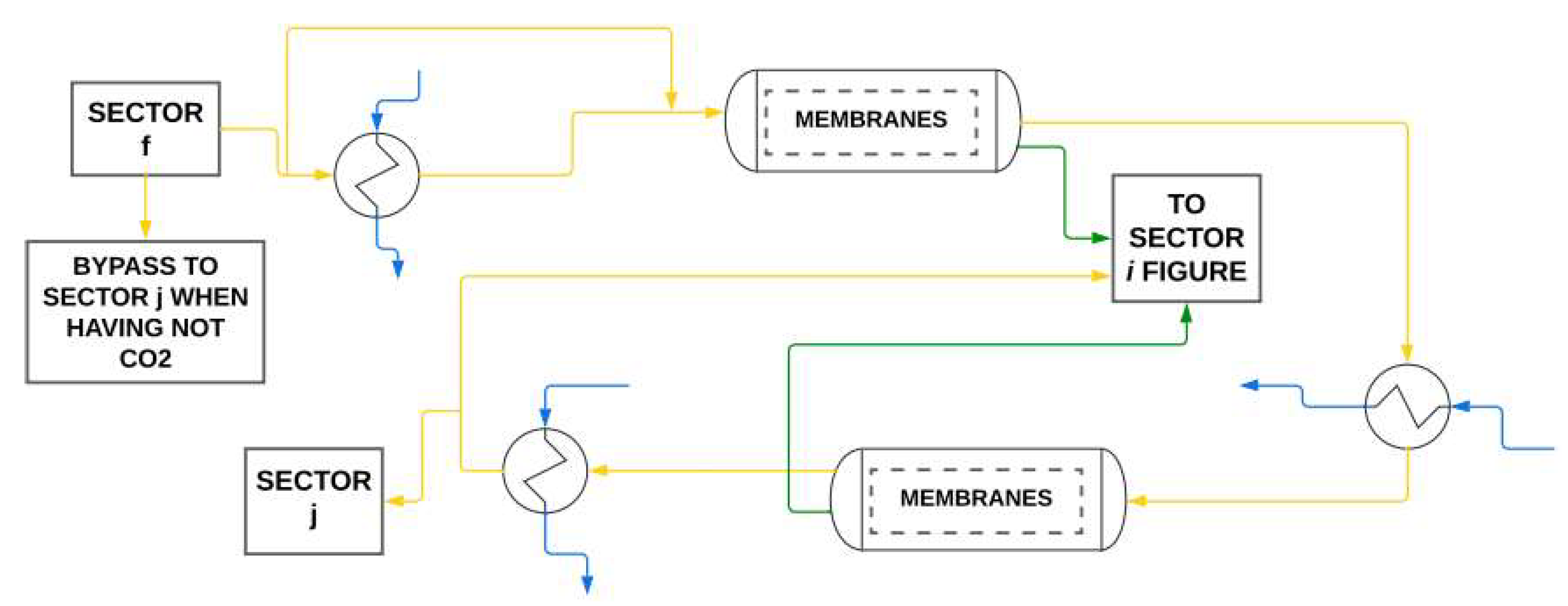
Figure 3.8.1.
Main streams of Sector h in a simplified process flow diagram. Gas as yellow, utility water as blue, CO2/CO as green.
Figure 3.8.1.
Main streams of Sector h in a simplified process flow diagram. Gas as yellow, utility water as blue, CO2/CO as green.
is the energy required to compress the minimal amount of CO2 that makes the process safety to perform the gas lift operation when the well needs pressure from it to lift oil, e.g., around 30 to 50 MPa of CO2 stream. Meaning that part of the CO2 can be used to gas lift within the hydrocarbon gases. is the energy available to the sector h. Eq. 3.8.3 represents electricity bounds.
Sector h is typically composed of two batteries (chambers) of membranes on series. The gas that enters the first battery must be heated to optimally operate and be separated into two streams, one rich in CO2 and the other with low CO2 composition. The separation in the membranes liberates heat, in which the product stream must be cooled by cold water (Eq. 3.8.4).
is the minimal mass flow of cold water necessary to specify all the stream temperatures entering in the second battery of membranes and the stream temperatures of gases ready for reinjection in the sector i. is the upper bound of mass flow of cold water available to sector i. is the mass flow of cold water used in heat exchangers after the batteries of membranes. The mass balance of water in the sector h is represented by Eq. 3.8.5. is the mass flow of steam that must be provided for sector h.
Petrobras patented an invention of a system to separate CO2 within the subsea (HISEP®), which is scheduled to be deployed in 2028 in the pre-salt oil production wherein CO2 concentrations are high as well as the Gas-Oil ratio (GOR). If it is the case to use this technology or any other similar, then in the planning optimization, the present CO2 separation sector can be or not disregarded in case there is no CO2 left sent to the platform. Note that this conceptual subsea project's objective is to separate the most part of CO2, but not entirely. Before the membranes receive the hydrocarbon gases, they must be heated to achieve a temperature that maximizes the performance of the membrane separation, something around 323 K depending on membranes. For doing that, either is used steam or hot liquid water (Eq. 3.8.6). Even if there is CO2 being produced through wells and if there is no interest nor infrastructure to sell gas, the present model automatically reinjects all gases in the reservoir/wells, including CO2, and one just may consider the composition as being zero because is zero in this case.
3.9. Gas Lift/ Export/Import/Reinjection (Sector i)
The sectors j and i are responsible for compressing the dry gases (hydrocarbon gases and/or CO2/CO) to reinject in the wells, either as gas lift or gas for well revitalization or as non-sold excess of gas due to a lack of infrastructure or demand. This sector i receives CO2/CO from the sector h and mixes it with the main hydrocarbon gas streams being sent to reinjection, completing a miscible CO2-EOR, and commonly has parallel systems that use one compressor each. Note that the present model is also compatible with immiscible CO2-EOR. Therefore, for each system it has a compressor using electricity and further cold water for cooling the gas before injection. This can be seen in the following constraints (Eq. 3.9.1 – 3.9.3) and in Figure 3.9.1. For a detailed study in CO2-EOR methods, see Fath and Pouranfard (2014). Gas lift is generally an injection in the tubing with the intent to reduce the head density while gas injection is in the wells and have the intent to increase the reservoir's pressure (CO2, hydrocarbon or N2 injection), but both can here be named as reinjection since the produced gas is looping.
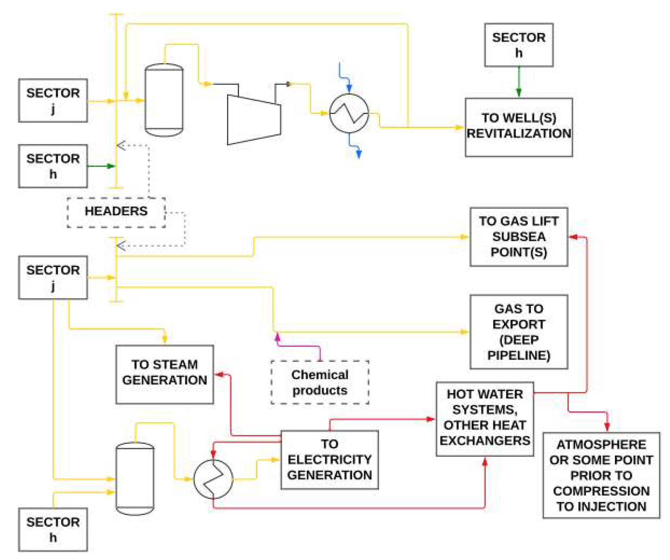
Figure 3.9.1.
Main streams of Sector j in a simplified process flow diagram. Product gas as yellow, CO2/CO as green, CO2/CO from turbogenerators' outlet as red, utility water as blue, chemical products to improve flow control and product quality as pink.
Figure 3.9.1.
Main streams of Sector j in a simplified process flow diagram. Product gas as yellow, CO2/CO as green, CO2/CO from turbogenerators' outlet as red, utility water as blue, chemical products to improve flow control and product quality as pink.
The mass balance given by Eq. 3.9.3 respects the conservation of mass and considers that all burned hydrocarbon gases become CO2/CO, if not then just specify efficiency. According to this mass balance, in this planning model, the CO2 of the chimney/kiln after electricity production is also exported as gas lift. The reason for this is to provide an optional more sustainable production. In practice, this optional conceptual project has the sector i connected to the flare, but only for safety purposes. In this stage, the quantity of gas going to the flare due to operational problems should be considerably lower than in the previous sectors and because of this is not considered in this model. Connections to the flare in the sectors j and h can also be neglected for the present modeling purpose but must be connected in the plant. Whenever gas is polytropic compressed in this sector, it must be cooled in heat exchangers using an amount of utility water (Eq. 3.9.4).
3.10. Water Systems for all Sectors
For start-up and maintenance of the whole platform operation, water utility must be available. In this section some important equations and constraints are discussed for water production, storage, and disposal overboard, as well as heat efficiency. A heating system utility traditionally can use high-pressurized hot liquid water in oil production facilities or steam. The present model assumes the use of steam to modeling and heat the hydrocarbon streams, a smart proposal, since in that way, the condensate hot liquid water can easily be returned to the boiler to save energy and generate recycled steam to use it finally, saving production of entropy by transferring latent heat. It controls the amount of latent heat transferred without loss of temperature in the water side medium and saves electricity avoiding the use of pumps. Even if one wants to use hot water in the platform, its quantity can be calculated by simply considering modeling with steam and then calculating what is the equivalent amount of energy that would be equivalent by using hot water. Eq. 3.10.1 creates an optional production behavior for the water capacity and the variables bonded to it in any way.
is the cardinality of the set t, i.e., the numerical representation of the planning horizon. is a number responsible to create a limiting behavior of how water must be stored along the planning horizon. Higher values mean that the problem is less relaxed but also has less variability in along the planning horizon. The global mass balance of water is given by Eq. 3.10.2 knowing that can satisfy , but is not obligated to since is what is stored at the end of time t. Water injection is the most used secondary recovery process in offshore fields in Brazil, is the mass flow of water injected in the reservoir. Local variables in the mass balance of water do not influence the quantity of water stored since what goes to a sector comes out from it; therefore, Eq. 3.10.2 is replaced by the global mass balance of water given by Eq. 3.10.3.
If total or part of the produced water is not in the needed composition quality to be processed and reinjected in the injection wells, then it needs to be discharged to the sea, and in this case one must just specify this amount in the lower bound of . can be a water excess to be destinated to daily mandatory utilities such as water for scrubbers, dilution water etc. is the mass flow of water being evaporated in the thermal vessel if the water reaches evaporating conditions in such stage and if the platform has hot water pumping. is the amount of water that is set to evaporate to the atmosphere or is liberated to alleviate pressure in steams' lines. The mass balance of utility water is given by Eq. 3.10.4. is the amount of mass flow of water that must have internally in the closed-loop water utility system. Generally, it is filled with clean/treated water before operation starts. The lung capacity must never be exceeded in a time t and must never be less than a certain amount in a time t (Eq. 3.10.6 and Eq. 3.10.7).
is the treated seawater if needed to be captured and the user can manipulate its bounds for minimizing it. Its upper bound is the treated seawater design capacity of the platform. For example, this paper's study case considered it with null value. Besides, to minimize it as a variable, one can just add a subtraction term in the objective function that is the seawater multiplied by a small number to force to minimize this term as possible to maximize the objective function. With this strategy the algorithm will try to minimize this term to maximize oil production but in the case that the objective function is the MPC, this term must be an addition if the objective is to minimize the error. This comes up with the goal to maximize oil production without treating seawater or minimizing its use, making production cheaper. Seawater treating unit is not modeled here since its wastes and utilities do not influence in maximizing oil production, and if treated water amount is determined, needed operation (elimination of sulfate, bacteria, oxygen, fine particles) can easily be specified. If production is onshore, this water could be from river. In an analogy, the same is done for , and can be done for and .
If the management leader desires controllability being lesser than the tank physical capacity, using Eq. 3.10.6 would make it not necessary to create other constraint, i.e., is just needed to specify as being an upper bound control limit. Optatively, since is a slack variable in the model, instead of using Eq. 3.10.6 and Eq. 3.10.7, it can be stated an operation to make the lung tank volume constant given by Eq. 3.10.8. The inventory can be controlled by Eq. 3.10.8 and Eq. 3.10.9. As is a slack variable, using Eq. 3.10.8 and Eq. 3.10.9 increase the tightness of the model, then using only Eq. 3.10.8 or Eq. 3.10.9 makes it more robust. Adding at least a constraint (Eq. 3.10.9 or Eq. 3.10.10) to restrain behavior is essential to create bounds for any planning horizon. The constraint given by Eq. 3.10.9 is more efficient than Eq. 3.10.10 because it creates a direct link between and inventory control. Throwing water overboard because of a lack in planning is also pollution, and the present model can preclude this by optimally reducing or eliminating , mainly when it was already injected many water that came from seawater treating, which are enough to create a closed water loop.
Either or can be the amount in which environmental regulatory agencies or engineering standards stipulate as maximum allowed. Eq. 3.10.8 to Eq. 3.10.10 are optative and serve only to control the quality of the decision-making of water variables, and it is a tradeoff between model robustness and quality provided, being recommended for short-term planning. can be intuitively equal to or lesser for more slack security. is the minimal composition of that can assume creating a lower bound for it. is the maximum composition of that can assume creating an upper bound for it.
The present model considers material and heat balances for calculation of water process variables, but an alternative way to restrain water utilities are given by Eq. 3.10.11 and Eq. 3.10.12. If the utility system having water is filled with produced and treated water within the platform, then what is being used of water as utility must always be equal to or lesser than what have available (Eq. 3.10.11). In the alternative setting, the constraint given by Eq. 3.10.12 works together with Eq. 3.10.11 and precludes that will never be equal to zero in any time t. Additionally, Eq. 3.10.11 could be suppressed if Eq. 3.10.12 is used.
Mostly, a better strategy is to not use Eq. 3.10.11 and Eq. 3.10.12 as is not wise to consider this restraint in the process operation since the water used as utility must edge the purity to avoid process issues. Therefore, this model avoids the use of these both constraints and consider the operational planning having the amount as being calculated by this model and being fulfilled independently from the global mass balance considered for .
is the amount of production water that is sent to the wells in a day t. is the minimal amount of utility cold water that must be available in t, and it is generally specified or calculated prior to optimization because cold water is a continuous closed-loop system; therefore, there is no need to consider it in the global mass balance of water. As is also within a continuous closed-loop system, it is not computed in this global mass balance (Eq. 3.10.3). is just to compute the quantity of closed-loop mass of water that is being used in the closed-loop systems. is the minimal amount of water that must be available in the sector b1 in t to provide that the oil stays within the operational temperature of storage. is the minimal amount of water that must be available in the sector c in t to provide that the water stays within the operational temperature of the hydrocyclones, something about 301.5 K. is the amount of mass flow of hot water that can be formed through the conversion of steam (Eq. 3.10.13), and it is a variable for the scheduling that provides a slack in the operational planning and technical process control.
Not necessarily all the amount contained in goes into the water lung tank, it depends on its current capacity. Despite that, directly filling the lung tank with the crude water coming from sector b1 is not smart nor recommended as it has impurities. The planning must ensure that it has water enough in the platform for doing the essential work, even in the start-up day(s) for achieving accumulated oil extrema faster.
Global heat transfer is established for establishing heat efficiency to the whole platform and for each sector in which are of interest to increase the temperature of hydrocarbon fluids flowing through the piping systems and equipment. The heat balance is the equation that provides the minimal mass flow of steam that must be generated in the water boiler to distribute along the sectors besides conduction and convex transfer heat. The heat balance equations are given by Eq. 3.10.14 (planning thermal energy required) and Eq. 3.10.15, and they force such operations to reconcile the slack amount of thermodynamic energy needed to achieve the wanted states. The RHS is all the heat available, while the LHS is the estimated heat that must be received. Note that gas turbine generators' (GTG) or GTCC's exhausting gases can generate hot water or steam, so this heat available in any of both forms must also be considered in and .
A good planning to large-scale processes must work with slack in utilities to provide feasibility against uncertainties, mainly epistemics, and indeed it occurs in practice. In this step we have the freedom to decide the amount of thermal energy it will be generated since it is a planning. In the heat equations (Eq. 3.10.14 and Eq. 3.10.15), the temperature gradient and heat provided by mixture properties are being disregarded since they are much less than latent heat and because thermal conduction and convection are performed through metallic piping and systems. is the platform average energy used to increase one kg of flowing petroleum or mixture in one degree kelvin. In ideal conditions, almost liquid phase and Newtonian fluid or low pressures, it can be approximated as being the specific heat of the fluid. Each specific point or sector s that is being used heat can be considered in the model as having a specific constant . is the water enthalpy of change of vapor phase to liquid. is the latent heat of water steam. is the mass flow being heated in a sector s. is the steam mass flow that must be provided for sector s. is the mass flow of the hydrocarbon stream that is being heated, e.g., for the sector b1 it is . In the case of , it is equal to minus the quantity of CO2 that is specified to leave within the flare system. is the estimated heat due to steam or hot water liquid phase heat transfer after steam condensation if any or because of inputting both steam and hot water or due to heat integration with other streams. is the sum of each . Letting any of equal to zero is not wrong but will just plan to produce/waste more steam/heat. Each of is generally specified and calculated in the basic and detailed engineering design phase of the project but can be used here as a variable or parameter for conceptual design.
In the sector f, only around 10% of the gas stream going out from the sector is being heated for returning to the molecular sieves, then in this case the mass considered in calculations should be 10% of , or other specified value. This specified value (10%) could be optimized through a Fine-Tuned Robust Optimization (Barbosa Filho and da Silva Neiro, 2022) rather than declaring this parameter as a variable, what would make the model nonlinear and less robust. In addition, linear solvers are more powerful than nonlinear ones, in any sense.
is the number of times that the mass flow is being heated, or the number of heat exchangers heating in different stages not being in series. As this is a planning model, these heat calculations do not need to be rigorous, yet using first laws, since the objective is to provide linear models for being more robust for any scenario. is an intrinsic property of hydrocarbon streams and it is the global difference of temperature required to operate the process in a sector s, meaning it is the difference between required maximal and minimal fluid temperature of a sector s being heated (Eq. 3.10.16). By this definition, process heating operation is guaranteed. This planning strategy ensures that there will be energy available to respond to daily operations, even if hot liquid water is used instead of steam.
The whole platform can use steam for a specific end, but the processes using hot liquid water or steam focusing as a utility for production systems are the sectors b1, f and h. The present model also serves as basis for calculation of the amount of hot liquid water and its thermodynamics conditions that would provide the same results. Each process needs amount of heat to normally operate. There exists a temperature, pressure, flow conditions, material properties and equipment sizing that transfer the same amount of heat using hot liquid water than steam. Once determined , calculating the amount of hot water is made apart and after the optimization of the present model is performed because it is a nonlinear calculation that would make the model less robust and slower without necessity. In addition, a local optimal solution could be found. Hot water calculation is needed if the plant does not have a process design to provide enough steam. Generating steam provides a cheaper system and less existence and maintenance of pumps, as well as less mass flow of water need to be biologically and chemically treated to provide the necessary heat. The present model can also use steam driven turbines for compressors, but a generic update should be made to the model.
Sectors b2 and d are the main sectors wherein there is phase change and condensation of gas into oil (hydrocarbon liquid recovery); therefore, the best option to provide process control is to calculate their utility water parameters as being variables. Although sector's b2 cold water is not being calculated through a heat balance as the way above, it could have been done similarly. In this way, , , and , would not be controlled as being a specified setpoint in a control system. Instead, it would be a setpoint calculated by this model and then controlled by a practical in-plant control system (e.g., as Eq. 3.10.17). Specifying possible setpoints instead of calculating could flexible the model against the systems' MAWP as well as other process variables. Rigorous calculations could lead to nonlinear models, and in the end may be controlled any way.
As sector d deals with all the stream gas that is processed within the platform, for this purpose it is considered constraints dealing with heat balance since in this stage a more detailed mapping is needed. Besides that, all the gas flowing in sector b2 is destined to flow in sector d. Since sector d processes much more gases than sector b2, the mass amount of utility flowing through sector d is bigger, and because of that it must be more rigorous calculated if not specified; so thus, it is possible to configure a less conservative process control and stability. The following constraints (Eq. 3.10.17 and Eq. 3.10.18) include the heat balance approach considered with its parameters and conditions.
is the number of times that a heat exchanger is used to cool the main gas stream. is the mass flow of cooling water used as utility in the sector d in time t. has the same meaning as , having in this case the fluid as being the gas being cooled. has the same meaning as . is the total transferred thermal energy required to cool the gas in all the stages of the heat exchangers where they are used. is generally a nonlinear calculus and may be the sum of different nonlinear terms; therefore, it is recommended that the user treats it as a parameter being calculated prior to optimization. For example, having an overall heat transfer coefficient , the specified thermal area , and , it is possible to calculate , remaining with a linear approach and surely a global optimal solution. can be either a parameter or a variable for decision-making or process designs. Designing new heat unit processes can be done by setting as being a parameter and optimizing its value through, e.g., a Fine-Tuned Robust Optimization method with other desired parameters instead of being worried about nonlinearity. If is calculated before optimization is done, then must not be here specified and will act as being a decision variable.
Generally, the amount of hot water and/or steam that must be produced generates variability according to initial inventory values for the water stored. Since overboard water directly influences storage, Eq. 3.10.19 or Eq. 3.10.20 provide optional controllability for the water in excess being disposed overboard to control the inventory in case it is necessary. They provide a remote upper bound specified by the user. determines how much the average upper bound can be varied to limit . The philosophy of Eq. 3.7.28 and Eq. 3.7.29 can also be applied to this step (and vice versa) and to .
For an empty water inventory, or a low level one, as the plant is susceptible to instabilities and dynamics, Eq. 3.10.7 must be relaxed in the first day(s) of just as Eq. 3.10.19 condition. Therefore, controllability is attended for water systems, and it must be noted that the company's management leader should choose between control options, e.g., selecting between either Eq. 3.10.19 or the one derived from the same philosophy but applied to (different water dynamic).
3.11. Subsea Constraints
In this section some constraints are presented to ensure that production on the platform meets the restrictions empowered by the wells and the subsea system. When the GOR (gas-oil ratio) is increased, the production has more gas, meaning more pressure and mass flow, i.e., more energy available. But there is a dependency between the GOR and the mass flow that goes up to the platform, including oil, gas, and water. This dependence is due to the pressure drop. In the same way, when the well has a lower GOR, it has more oil compared to gas and therefore it has more oil entering the platform. More crude oil means more money since it has more market value than natural gas. However, there are oil and gas processing capacities. What measure can be taken on the platform to maximize the oil and use the gas lift to benefit these favorable relation order? Previously we saw that is either a parameter or a variable but declaring it as a variable and inserting some constraints, the well pressure increment through the gas lift can be also manipulated throughout the platform process variables, sending the amount needed to maximize the optimization problem. Being the reservoir, the volume, the pressure, the density and the universal gas constant, respectively, the following mass balances resume this (Eq. 3.11.1 and Eq. 3.11.2).
Recycling streams and revitalizes the wells, while Eq. 3.11.1 says that the model is determining the compositions that must go to the platform. In practice for short periods, declines linearly reaching maximum equipment operation conditions, unless recovery methods are set to vary nonlinearly. relates the model with the recycling streams and the reservoir exploitable mass . Gas lift is a residual consequence of these compositions and all the set constraints being satisfied. Note that is included in value. It is logical to see that it will come a time in which the mass of hydrocarbons in the reservoir is going to make business infeasible or economically unattractive to big companies, as the wells become mature. For that, this planning model can be used to schedule production in a way that profitability is aligned with revitalization variables, e.g., and . One can set the upper bound as being the initial reservoir mass () because adding more material than before can compromise integrity.
Eq. 3.11.1 with the rest of the model smartly optimizes according to the available capacities, because, e.g., whenever any component mass flow is increased it will mandatorily increase the others but as the plant have limited capacities for each of them, must satisfy for all. This is one of the biggest challenges one will face trying to optimize production if not using a proper production scheduling model or heuristics at all. Moreover, this is the reason why when using manual override, the setpoint is periodically changed a lot fearing that inventory will collapse. Manual override is also a bad strategy because one cannot predict the platform sensitivity due to a change in the topside choke valve mass flow, risking the process safety and shooting in the dark trying to achieve optimal performance.
Water steam injection is a tertiary recovery method designed to warm the oil and decrease its viscosity and mixture density and are preferrable to recover remaining reservoir portion. Even if a company does not establish it as a typical practice in deep water gas lift operations, the model also considers liquid water, CO2/CO-EOR injection for carbon capture planning and sustainability. If one wants to make an optimal CAPEX prediction for reservoirs exploitation, then should consider this in mind.
3.12. Optional Subsea Specification or Synthesis: Linear or Nonlinear Pressure Constraints
The previous sections created an independent model, i.e., this section 3.12 is an optional extension. Generally, gas lift makes the role of reducing the density of the mixture () in the tubing to reduce pressure head till the topside. For environmental purposes CO2 from the well must be reinjected. For sustainable philosophy, it is being proposed the possibility to also reinject produced CO2/CO from the burning of gases. Besides, injecting CO2 and other gas either in the beginning of the wells or in the tubing will increase the available pressure to lift the oil, as well as modifying the viscosity and density in a favorable way.
Subsea pumping systems can provide higher production to low and medium profile pressure wells, but it comes to a point which the safe maximum operational point of the pump is attained, and other measures must be taken to maximize oil production. For example, density and viscosity, as well as mitigation of the harms of paraffins and asphaltenes can be favored by chemicals such as polymers, miscellaneous solution, surfactants, etc., as well as steam, hot water, CO2, and other techniques as approached in the present article.
The previous model is preferentially a MILP, and already monitors relationship between gas lift, water injection and remaining production capacity (Eq. 3.11.2), but to trace the needed pressure increment given to the lift system to optimize production, this section is written. To trace gas lift pressure potential with the reservoir current condition along planning horizon, there are few constraints that can be optionally considered for more efficiency in the aspect of monitoring reservoirs or wells. Typically, a platform producing 150,000 bopd and further has about four or more operating wells with a reservoir pressure (in bar), and the type and amount of material being injected in each specific well is determined by a geologist, or specified prior to optimization by the manager, but could also be appended within this model. The constraints given by Eq. 3.12.1 and 3.12.2 relate the pressure (in bar) with the pressure increment to either the tubing or reservoir which provides the available pressure leading the oil to the topside production. The steady-state design for energy balance in S.I. is given by Eq. 3.12.2. Energy from thermal loss is irrelevant compared to the main terms from this equation.
The pressure constraints are optional and make the model to be more difficult to solve, needing more experience in specifying the parameters. If the average of the wells is mature and because of this the pressure is low enough in the riser to not lift the gas, production needs a subsea pumping system to lift the flow, otherwise (in meters) is null. Having one or more pumps, their active power consumption must be computed in Eq. 3.7.16 considering conversion to power discounting pump efficiency and volumetric flow. Hydraulic pumping systems usually range from 2,000 to 4,000 psi, and can be used either as parameter or as a decision variable to the model if this mechanical condition is satisfied. Moreover, the mathematical pump term can have a binary variable for investment acquisition decision, but not limited to it, 1 if the subsea pumping system must be activated, 0 otherwise.

is the pressure loss since the reservoir up to the downstream of the choke valve, is the downstream pressure of the choke valve, g is the gravity, is the height between the reservoir and the topside choke valve. As being the internal piping area of the choke downstream, is its fluid velocity due to (Eq. 3.12.3). is the loss of energy due to friction and heat exchange within piping wall and subsea water. In a nonlinear modeling approach, can be linked to , in many different ways, empirical or approximated, e.g., in a conservative way could be divided by its linked volumetric flow value that could be measured by the volumetric flow metering instruments or based on tables, with a mixture correction factor.
For gas lift, a high-pressurized gas is injected into the production tubing of an oil well to reduce the hydrostatic pressure of the fluid column, allowing the reservoir pressure to push the oil to the surface more easily. It directly influences the value of the density in the topside choke valve and . When the gas-lift compressor(s) inject fluid providing pressure, the incoming pressure flowing straight to the topside is not currently the net pressure value given, it is indeed corrected by a factor that combines to give the real pressure increment . For tuning the model even more to the plant, is a small correction factor and is specified or determined with the running production through a signal converser with instruments assistance in the plant as a PDG. plays the role of added energy in the form of work. Eq. 3.12.3 relates Eq. 3.11.2 and Eq. 3.12.2.
The constraints given by Eq. 3.12.1 – 3.12.3 are important to increase the well lifespan when controlling the reservoir/well available lift pressure but note that Eq. 3.11.2 already plays this role more importantly. The term containing in Eq. 3.12.2 can be linearized towards an estimated point with a Taylor series, thus making a tie-in of to the model as being linear. Prior to defining this estimative, one can make a first optimization without including the optional pressure constraints, for then defining the point as being the velocity for the optimal value found (Eq. 3.12.3). Indeed, for the not long-term run, reservoir's pressure behaves linearly considering the whole huge amount of exploitable remaining days. If the nonlinear approach is considered, Eq. 3.12.2 and Eq. 3.12.3 would still be convex.
As reservoir fluid is supercritical, then rigorous calculation of requires nonlinear calculation and could be predicted by the following constraint (Eq. 3.12.4). The optional pressure constraints inserted to the model works very well for linear applications and short to medium term scheduling, but when considering nonlinearity like in Eq. 3.12.4, the model can predict more rigorously for long-term run because Eq. 3.11.2 integrates Eq. 3.12.4 to the whole model. Initial estimation values for modelling purposes can be determined for by specifying and dividing it by its density . One can add a correction term in the RHS of Eq. 3.12.4. Including Eq. 3.12.4 in the model allows the monitoring of reservoir pressure along the planning horizon, which constitutes a formal strategy for CAPEX and OPEX prediction.
is the pressure head in the reservoir/well, is the compressibility factor considering the supercritical fluid, is the exploitable mass of the hydrocarbon fluid in the reservoir, is the universal gas constant, and are the temperature and volume of the reservoir. is the average molecular weight and is the reservoir volume. One of the following two constraints (Eq. 3.12.5 or 3.12.6) must be applied in both cases, the linear and nonlinear case; if the reservoir is new to production, Eq. 3.12.5 is used, but if it is not then Eq. 3.12.6 is used. An initial estimate with other techniques can also be made.
is the density of the virgin reservoir or set of wells, is the exploitable mass of the virgin reservoir or set of wells. is an average of the mass flow that had been exploited. is the cardinality value of the set of time the reservoir had been being exploited in the past before to the present optimization application. In rigorous calculation, the density is a function of temperature, pressure, and composition, and experiments must be made to model the art, which is not the scope of the present paper to append it. The calculation of , , and are nonlinear, therefore making the model naturally less robust. In this article, we disclose the architecture of the nonlinear structure instead of developing complex structures, e.g., calculation of and vary on the scenario they are being applied, then being determined by new investigations, or demands accordingly. Estimation of the kinetic term is valid in this case since potential energy is way higher than it.
Since is a function of the pressure of the well and of the pressure of injection, which can be manipulated in the platform, then can be written as a function of the total mass flow coming to the platform , since the pressure of injection is related to it. Alternatively, can be related to as it is an increment given to the tubing pressure. For security purposes, having a fully opened control valve (fail-safe closed) or a block one (locked open) after the compressor and disregarding head loss since diameters are usually around 12 inches nominal with gas/vapor phase, the relationship between and can be given by simplified IEC 60534-2-1 (SAMSOM AG, Frankfurt, Germany), Eq. 3.12.7 or Eq. 3.12.8 () or other constitutive original equation from IEC 60534-2-1. is generally controlled by the compressor (Eq. 3.12.7) that manipulates a pressure in its downstream. It is important to note that the same artifice can be applied to the topside choke valve to once more time link all optional pressure constraints to the rest of the model through and related pressures. Putting such pressures as parameters, the model remains linear and controlled.
The definition of is the weighted average of multiple valves' values that are inserted along the line multiplied by their valve opening percentage value. If is a low value, it means that either the value or the valve opening percentage is a low value, or both are. When running an MPC one should note that any equation from IEC 60534-2-1 must be inserted here having concordance between concept and the mass flow unit. The number 24 in Eq. 3.12.7 or Eq. 3.12.8 is for in kg.d-1 which was the unit considered for the scheduling. As it is a multiperiod model, the unit may change according to the planner's choice. is the fluid temperature (K) in the downstream of the valve being used as gas lift. The line containing can further derive , , and other lift variables into different branches (other lines) and ends. Considering as a variable, one can either select for CAPEX investment or can observe what is the maximum value that converges the model using these optional pressure constraints with all specified parameters. as a variable also determines through a signal converter (connected to DCS) what are the valves' openings percentage that must be applied. Equations to calculate opening percentage can also be appended to this model but as plants may differ, this equation depends on its number of valves, strategy, etc. For planning and scheduling, letting being a variable, in the practice if the valve is already bought with a higher value than what the model calculates for , then the calculated value for divided by the current real selected value gives the characteristic function value related to the opening percentage that the value must operate. For linear opening, it would directly provide opening percentage.
Including Eq. 3.12.7 or Eq. 3.12.8 opens the opportunity to set as being a variable instead of parameter because the mass balance of gas lift will have more degree of freedom. Particularly, the units of Eq. 3.12.7 and Eq. 3.12.8 are following IEC 60534, i.e., density is given in S.I., and mass flow is given in kg.h-1 in which multiplying by 24 gives compliance to kg.day-1. minus is the average pressure drop in bar of all connections' pipes having valves flowing all kinds of gas lift of the platform. is the pressure of the fluid in the downstream side of the compressor(s). Eq. 3.12.2, 3.12.7, and 3.12.8 is mainly used together to calculate considering nonlinear setting of these optional constraints. On the other hand, if one does not want to calculate , and instead wants to specify this increment of pressure to the system, to then calculate using the MILP, then one just needs to suppress the use of Eq. 3.12.2 and only use Eq. 3.12.7 or Eq. 3.12.8. But in in this case, it is crucial and essential to declare as variable instead of parameter, to give some degree of freedom to . In other words, the linear case makes to be a function of , but one could use any other terms in Eq. 3.7.12 to be also a variable. If one specifies a pressure increment disproportional of how much the platform have of stored water and in Eq. 3.7.12 depends more on the term of , then the optimization is going to be infeasible of course, and tends to be zero (a nonlinear setting does not worry about this). In the present model, the mass balance of water is the most sensitive part. Note that even without calculating the pressure increment, Eq. 3.7.12 and Eq. 3.11.2 monitors value. Generally, value is insignificant compared to the other lift and reservoir variables.
Specifying upstream pressure and the required pressure drop (), the model adjusts and . These pressures must be coherently specified to give real or Cv values and must be linked to the valve's minimum and maximum operational and design flow from its datasheet. The optimization will be infeasible if the pressure specifications force the calculated material being reinjected to be greater than what is available. Eq. 3.12.9 and Eq. 3.12.10 must be activated if one wants to generate static setpoints that optimize production for the valves' opening percentage. refers to the topside choke valve. CO2 and hydrocarbon gas lift can be sent together or separately to the wells, compound some technique just as CO2-EOR.
If having more than one operating choke valve in topside, there is no problem because would be their average. Finally, since it is of interest to control fluid velocity on choke valve downstream, it can be made controlling valves opening, then the total pressure drop is a variable that controls , which is also a variable in this case. Choosing this philosophy, the velocity must be bounded according to Eq. 3.12.11 or Eq. 3.12.12. is the maximum allowed velocity but is not limited to it, i.e., can be specified below it or can be a setpoint . can be but is not limited to Eq. 3.12.13.
The handling of the model consists according to the parameterization given, if one does not know a good strategy to create feasible optimal solutions based on the parameters that were specified, a strategy should be created. A well one is to increase a slack variable in the RHS of Eq. 3.7.12 (no physical meaning), then with the feasible optimal solution in hands take this value to increment in variables of the RHS. It serves as a basis to know capability of the model on handling gas lift according to all specified parameters, and to give insights of what needs. If during construction of the present model, some optimizations get infeasible check if according to given parameters, the model cannot create utility to the current amount of water or electricity available.
The entire model works for any planning horizon. Exceptions for the rigorous model setting must be noted when it is wanted to calculate the gas lift pressure. The linear approximation serves rigorously better to short-term and medium-term. The reason is because only the nonlinear setting rigorously represents the decrease of along the planning horizon by considering rigorous thermodynamic calculations or other theories for supercritical fluids.
Including these subsea optional constraints for long-term run is interesting if one wants to monitor the reservoir or well pressure decrease over time. The linear setting does not prejudice the long-term run to monitor subsea exploitable mass, not even rigorously since the model conservates material balances. Moreover, for rigorous optimization, one optimization for CAPEX planning can be done using the linear setting by loop-solving the model using input updates at the end of each planning scenario.
3.13. Platform Energy and Renewable Energy
If there is an offshore wind power plant next to the oil production facility, or even any other external renewable power source , then this electricity can be provided to the oil platform as well. For sustainable and efficient production, renewable energy may be considered (Eq. 3.13.1). If one wants to make a design study, can be an integrated variable through inserting its new and specific constraints and equations to the current model to develop economic analysis in deciding till when and whether is worthy to use the studied energy. The present model also can be used to integrate offshore wind power and to design the system to determine how it should be configured to make production of oil feasible and optimal subject to the dynamics. is the electricity setpoint provided by GTCC, if there is any.
Whenever there is not gas enough available or the stage of production is near this condition, part or total (worst case) of the electricity can be generated using MGO . When the producer wells have a limited pressure/gas only around the sufficient to lift the oil, it means production is near infeasibility, and for this, the present model can be used to foresee when is going to happen and to make it optimally feasible by determining .
4. Case Study—Results and Discussion
In this section, three optimization cases with the same inputs were studied and analyzed, first a short-term and medium-term scheduling, then a long-term scheduling, and finally a short-term automatic MPC. The units of the figures are in kilograms per day for mass flow variables, bar for pressure and Joules per day for electricity. GLPK (GNU project, 2012) was used as the solver, and Pyomo (Hart et al., 2011; Bynum et al., 2021) was used for model construction in Python 3.
The philosophy on helping convergency, as well as to faster achieve oil extrema with the generated decision-making, is to always have an optimal available inventory of gas and water at the next time t since they are being constantly subtracted to manipulate the platform and subsea variables. The model optimizes it for the user. In this sense, commissioning is the most dynamical and difficult period of production; therefore, to illustrate the strong robustness and efficiency of the model, the present study case's optimizations consider the startup mode with empty inventories for the oil, gas, and water, and with pressurized equipment. As the sectors b2, d, j and h have flare variables, flaring can also be predicted for first oil or start-up sealing gas for compressors etc. The user can add any new flare variables that feel convenient when adapting to new plants. Since the model is capable of scheduling for the startup, the “steady-state” operational mode and shutdown is way easier to be applied.
The present study case is based on actual trustworthy industrial large-scale data range similar to of the FPSO P-75 and MV32. Important results from the execution of the MILP version of the model are shown. The interest is in showing the linear performance due to its natural highest robustness for large-scale systems, computational tractability and velocity compared to the MINLP, which are important parameters to the scheduling and crucial to the plantwide linear MPC. Note that for a planning horizon of 30 days, the model has around 3153 variables and 5171 constraints, then presenting all results in a paper should be out of space. The focus is on showing results, orders, and trends graphically to demonstrate how the model can be practically deployed since it determines static setpoints (and partial — multiple statics — if wanted), even under uncertainty and in a dynamical environment, and decision-making is smooth. The most common uncertainties in an oil platform are the feed compositions and mass flows.
The study case comprises a production with 6 active wells with a total of 150,000 bopd subsea/upcoming topside oil mass flow capacity with around 53 MMscfd natural gas production exportation through pipeline and a 265 MMscf LNG gas supply to a tanker whenever offloading is performed (which is not necessarily obligated to depart for routing in the same offloading day). The case study considers a reservoir reinjection of hydrocarbon gas up to 135 MMscfd and of CO2 up to 101MMscfd. The minimum water injection is 180,000 bwpd (rated maximum 280,000 bwpd). A hydrocarbon gas-lift not exceeding 6 MMscfd per well, and a hydrocarbon gas reinjection to the reservoir whenever the model decides that is needed for controlling the inventory. The actual incoming mass flow under composition uncertainty that can also represent slug flow when not annular is represented by a normal distribution for each t with means and standard deviation (0.299, 0.01), (0.157, 0.0015), for gas, and water, respectively (the rest for oil). This uncertainty configuration can represent and simulate slug flows whenever a random number is generated in the right band’s tail of the normal distribution curve for gas and in the left tail for oil. The gas feed composition is composed of 28% CO2 with 0.5% H2S and all CO2 is reinjected in the reservoir to not harm the global warming as a regulatory compliance. Regarding the three-phase horizontal vessel and producers, gas and water feed were optimized with a processing current production of 69.391 kg.s-1 and 76,000 bwpd, respectively. Regarding electricity generation, the case study case comprises three working GTGs providing 79 MW, and the other in standby. Production depends on chemical feed composition, equipment design, PVT, etc. All the optimizations studied have the same inputs. The comparative made along section 4 to some FPSOs operating in the Brazilian offshore were taken from a recent public official governmental database available online from 07/2022 to 08/2023 for continuous operation during campaign and from 08/2023 to 10/2023 to FPSO MV32's first oil dynamics. MV32's official first oil was in May 2023, but the production was not full yet up to 10/2023.
The way the model was created, and because the objective function is the summatory of time-dependent variables, makes the model adequate solution for the whole planning horizon. For example, if the model is solved for a planning horizon of 10 years, the decision-making is not mandatorily going to be the same for its 30 first days compared to the decision-making of a solved optimization run for a planning horizon consisting only of 30 days. Only inserting constraints providing bonds and controls can be responsible to provide quality for the decision-making when slack variables are involved, because a rule/logic must be provided to control either the slack, inventory or lift variables, this is one reason why constraints such as Eq. 3.7.28, 3.7.29, 3.10.9, 3.10.19 and 3.10.20 were modeled. As in an optimization problem, the degree of freedom is not zero, and not ignoring this philosophy in the present model is essential. It is trivial to note that, because there is controllability being done, it is common to have variability in variables affected by other controlling variables, or because of the initial inventory — different values create distinct dynamics. Even the defined kind of controllability creates a specific dynamic.
Eq. 4.1 was used for estimation of instead of making a regression for the calculation of Eq. 3.7.17. is the lower calorific power of the fluid in J.kg-1. is the electrical yield of the thermal machine generating power related to . In practice, it will determine how much power is generated from combustion. and can be related to methane, ethane, propane and butane. Moreover, it is smart to let have majority amounts of ethane, propane and butane if there is not an LPG supply chain; therefore, making the reinjection more dependent on natural gas, and making it constituting the major value of .
was derived for Eq. 4.2 to give the pressure loss (in bar) of the fluid passing into the topside choke valve. is the pressure drop in all the piping from the reservoir's level up to the upstream of the topside choke valve, including loss from previous valves other than the topside choke valve. Each of these valves' opening percentage along the way influences the value of . In practice, can be a variable to control the model and is bounded within the maximum and minimum opening percentage values plus static pressure drops.
The upstream pressure of the topside choke valve is a parameter that varies due to the slug flow (disturbance/uncertainty). Eq. 4.3 shows the pressure drop of the fluid through the topside choke valve in function of the downstream pressure that also appears in Eq. 3.12.2. The Eq. 4.3 serves to control the topside choke valve downstream pressure and to compute upstream pressure disturbances and variations through sensors/transmitters or specification.
4.1. Case Example: Short and Medium-Term Planning and Scheduling
Firstly, the model was applied to a planning horizon of 90 days to provide production scheduling and decision-making for an OPEX-typical planning horizon visualization and robustness. The optimization is under uncertainty just as in practice. The optimization provides the setpoints and decision-making to maximize oil, e.g., the topside choke valve opening percentage, compressors' active power, mass flows, electricity generation and usage, etc. The result plots from this kind of planning horizon regarding production and global variables for this case are shown in Figure 4.1.1—4.1.8. Figure 4.1.1 shows the production comparative to some FPSOs operating in the Brazilian offshore. Observe that because of the process safety, the decision-making will not let the topside choke valve pass any amount of mass flow that is greater than the subsea and process design capacity. For an example of the model's efficiency, Figure 4.1.1 is based in days and plots the setpoint of the actual case study's topside choke valve's mass flow. Figure 4.1.1 plots a comparison between some Brazilian operating FPSOs acting in the pre-salt field, having the same oil processing rated design capacity of the study case. The user may bear in mind that all the other decision-making variables from the model give setpoints and/or must be scheduled to make the solution optimal and a feasible planning. The comparison shows that for the case study's inputs, the optimal solution and decision-making showed superiority compared to the actual operating FPSOs. Having as a basis Figure 4.1.1 and the inputs exposed, the results showed that the present model provides: 1) an increase of around 101.5% on a start-up after first oil production compared to the MV32 (in a full operation with all well producers); and 2) a 10.5% increase during campaign (continuous operation) compared to the FPSO P-75 which had one of the biggest productions within the compared FPSOs, and both with a rated design of 150,000 bopd.
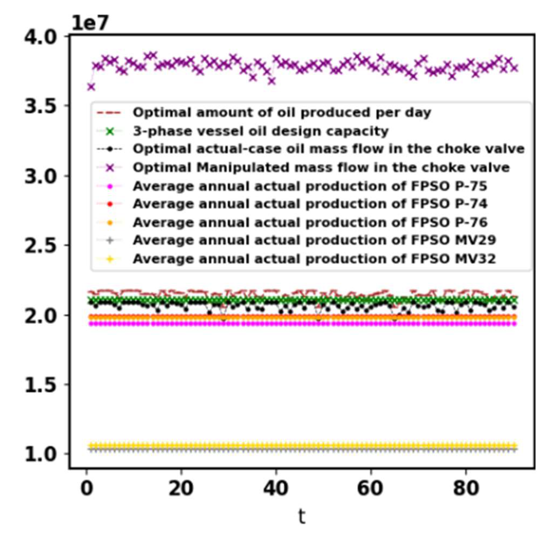


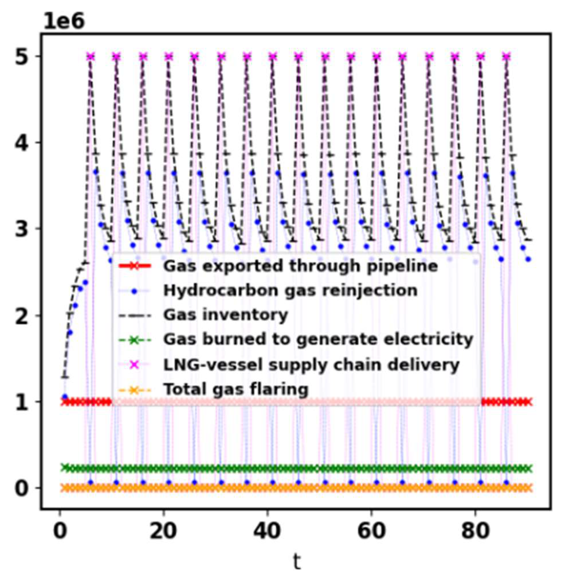
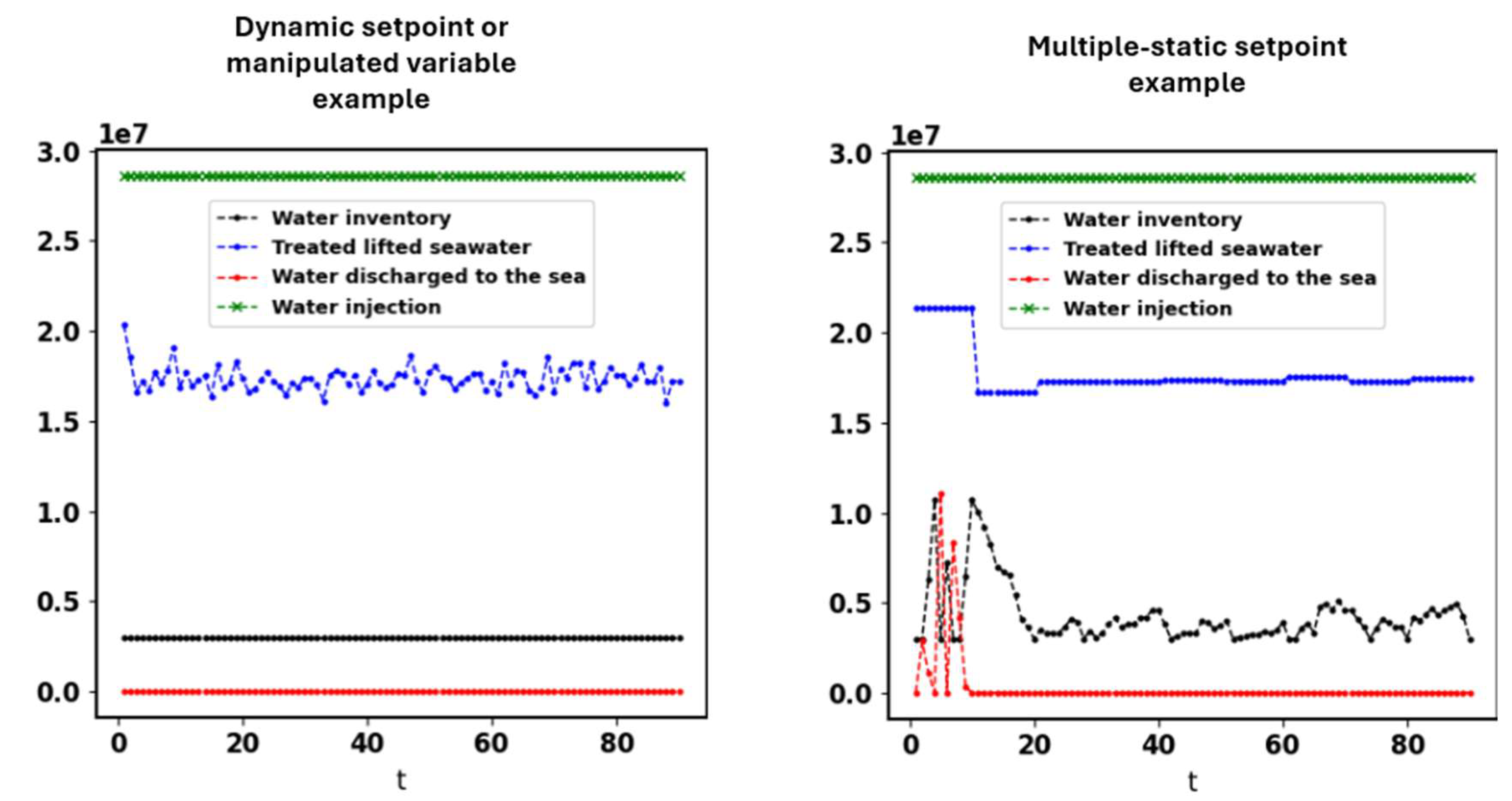

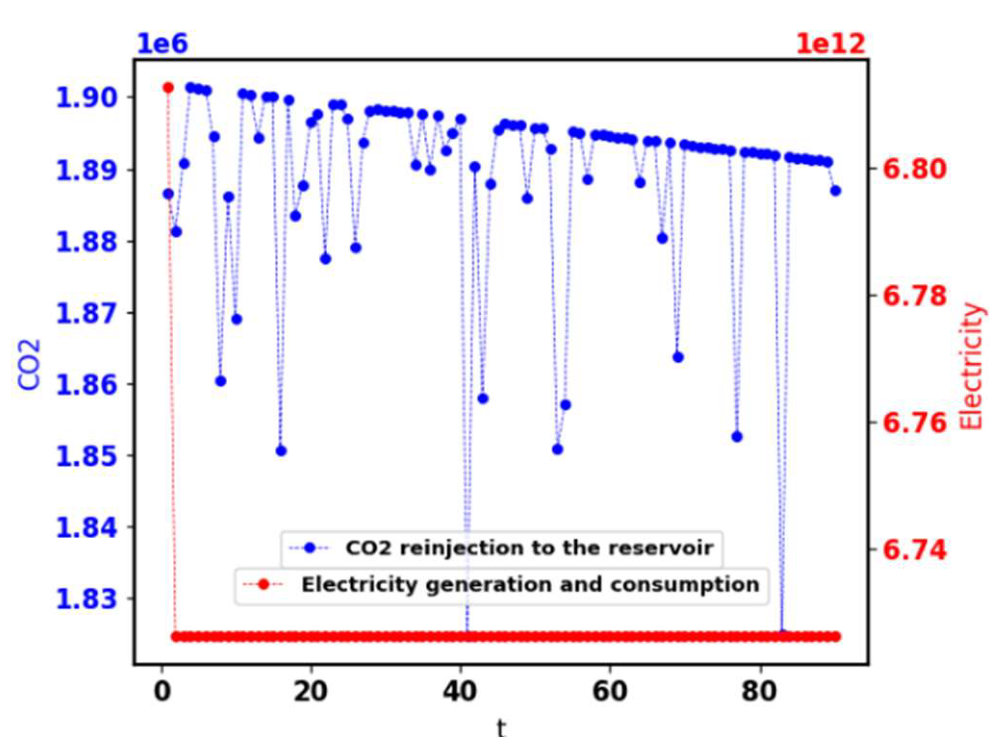
Figure 4.1.1.
Comparative of the oil production for a 90-day planning horizon.
Figure 4.1.2.
Reservoir pressure estimation for a 90-day planning horizon.
Figure 4.1.3.
Oil inventory including offloading to supply chain for a 90-day planning horizon.
Figure 4.1.4.
Hydrocarbon gas production and output global variables, inventory and offloading for a 90-day planning horizon.
Figure 4.1.4.
Hydrocarbon gas production and output global variables, inventory and offloading for a 90-day planning horizon.
Figure 4.1.5.
Water inventory and global variables for a 90-day planning horizon (in the left the dynamic setpoint, and in the right an extra showed case to demonstrate multiple-static setpoint example when activating MPC-based scheduling equation).
Figure 4.1.5.
Water inventory and global variables for a 90-day planning horizon (in the left the dynamic setpoint, and in the right an extra showed case to demonstrate multiple-static setpoint example when activating MPC-based scheduling equation).
Figure 4.1.6.
Sampled subsea production of oil and gas under uncertainty and decline while maximizing production for a 90-day planning horizon.
Figure 4.1.6.
Sampled subsea production of oil and gas under uncertainty and decline while maximizing production for a 90-day planning horizon.
Figure 4.1.7.
CO2 reinjection to the reservoir, and electricity generation and consumption for a 90-day planning horizon.
Figure 4.1.7.
CO2 reinjection to the reservoir, and electricity generation and consumption for a 90-day planning horizon.
The deterministic optimization is recommended when one wants to know the maximum possible safety value for the static setpoints that would not lead to potential trips, because this kind of optimization does not estimate slug flow or uncertainties that could leverage manipulated variables to a risky plateau of operational setting. For example, it is not wanted to let the topside choke valve be opened in a value that could pass more gas than the plant can process in an eventual slug flow. The optimization under uncertainty can predict slug flow and risky uncertainties while creating decision-making to avoid them. At the same time, solving the actual uncertainty problem with the MPC or the MPC-based scheduling can grant attenuation and constant or almost-constant variables' value setpoint, easy to make DCS or automatic logic configuration without needing manual override. On the other hand, if the scheduling is made through a deterministic optimization considering conservative upper bounds to , , and , it can generate static setpoints with process safety, because even in the problem under uncertainty, estimating/predicting variability is the difficult task, and was exemplified here by normal distributions. The right plot in Figure4.1.5 show values for the treated seawater mass flow as an example of how multiple-static setpoints can be generated over a planning horizon, while the gas amount burned to generate electricity and what is exported are example of static setpoints (Figure 4.1.4).
For sustainable purposes, the model also minimizes the amount of water discharged to the sea (Figure 4.1.5), and instead forces the scheduling to reinject it in the injection wells to control inventory respecting design capacity. It will only have water being discharged overboard if there is no more capacity to reinject water. The same sustainable philosophy will happen to the flaring systems and burning gas systems since the model reinjects all exceeding gas into the wells instead of burning it (Figure 4.1.4). The use of renewable energy is recommended for sustainability and is supported by specification and using Eq. 3.13.1. Not only singular technology in unit operations can provide sustainability. This model has shown that sustainability is also provided when organizing production, and a scheduling model is the only way that can plan it. Even the CO2 can be flared when a plant has a trip in the compressor owing to a lack of scheduling and needs to be depressurized. Optimal reconciliation between treated lifted seawater and water reinjection is what grants zero water discharged to the sea as can be seen in Figure 4.1.5. The scheduling was performed to execute the following decision-making described in Table 4.1.1.
This increase in production compared to other operating FPSOs can be due to the production with inventory control that is prone to not have trips or unplanned halts while producing without killing inventory at the same time emissions are minimized. Besides, optimal setpoints to maximize production are determined, which is a setting that heuristics or standardizations cannot measure mathematically in the actual constrained problem. Not all the inputs are decision-making variables, but most of them are when not being a physical property, or an equipment setting, etc. All the other decision-making parameters are specified as inputs which are also part of the decision plan as a whole and must be coherently specified by the user. For example, Table 4.1.2 shows an example of some important parameters on the role of manipulation of utilities, which could also be variables in the model. The rest of the inputs or outputs not shown must also be parameters or variables. The preference on choosing if a parameter should be a variable is up to the user depending on their needs.
The model is by its nature a maximizer of oil and production controller. Even without using the MPC multi-objective function, control can be attained if well scheduling the plant and of course using parallel regulatory control. Eq. 3.7.30 is the MPC-based scheduling key independent of what objective function is being used. Eq. 3.7.30 is modeled to stabilize the model outputs. Besides, the use of the automatic MPC will not preclude using regulatory control as well. The whole model works with its controllability stabilizing all topside variables throughout the platform. Including the second form of the objective function (Eq. 3.2C) creates a specific MPC which can be customized as it is wished according to the available variables and parameters, which will be discussed in section 4.3.
4.2. Case Example: Long-Term Planning and Scheduling, and Revitalization
When oil and gas are extracted, a void is generated in the spot they used to be placed, and for this, water or gas reinjection are used to increase the reservoir pressure and occupy this spot for not harming the physical integrity of the reservoir/wells. Therefore, manipulating and monitoring the reservoir's mass or pressure is essential to grant no voids and revitalize wells. The interest of a long-term planning is in knowing how long the production remains with historical high production pattern or steady even exporting gas and with a water injection condition to create a setting favorable for revitalization, which will grant in a long-term operation that the oil is lifted against the backpressure. A longer planning horizon of a 6-years case example was optimized, which is generally the time interval of a typical production around plateau. The CAPEX study has 360216 constraints and 221797 variables. The parameters for this example are the same, unless the water reinjection , which was assumed different values so a sensitivity analysis could be made. Figure 4.2.1 and Figure 4.2.2 show sensitivity analysis for the estimation for the revitalization due to . On this case, the oil production is the same from the previous examples, but the reservoir pressure declines differently. This long-term planning is recommended for the development of the design phase of an oil platform project or to predict till when it is going to be worthy to be exploited rather than move the FPSO to another reservoir.
Since the operation remains over a region in the pressure plot that is steady with closer values with the passing of the planning horizon in the timeline, a linear approach is considered robust and approximately rigorous, because plotting the reservoir pressure versus the time, even nonlinear reality can be a line when observed small time windows. Since revitalization can give little variation in the reservoir pressure, then it can be assumed that even for long-term planning the approach acts like it is running over small-time windows in the timeline and operating over a fixed operational point or region. Note that even having revitalization, oil and gas production capacities follow the same philosophy and modeling, and decline with time, while produced water generally increases.
The present example resulted in a maximum use of memory system equal to 3.9 GB RAM. Total execution time was nearly 16 minutes for an Intel(R) Xeon(R) CPU @ 2.20GHz with 4 vCPUs. A strategy to save time is setting some binary variables, e.g., just as , equal to 1 or 0 to eliminate exponential solving time due to this binary existence (user's criterium). Letting and being integers equal to 1, the system memory ram used decreases around 3.8%. For a planning horizon of 90 days, the solving time was only around one second. Solving time is just a reference since it depends on parameters and in the chosen and defined controllability. Initial estimate values were not a problem in the linear model. The execution run-time varied nonlinearly using Pyomo as bigger the planning horizon was.
The interpretation of Figure 4.2.1 and Figure 4.2.2 relies on reservoir integrity, revitalization and winning against backpressure and does not show the available oil and gas capacity like as in Figure 4.1.6. As can be seen in Figure 4.2.1 and Figure4.2.2, a small percentage increment in the water injection can cause either a great revitalization or can put the pressure or reservoir mass near the initial value, which could trespass it and create a risk for integrity. On the other hand, not reinjecting a reasonable amount of water is prone to let the subsea backpressure make the production infeasible. For process design, the optimal amount of water being injected can be determined when treating it as a decision variable and using it as a target in the objective function as the stated strategy in section 3.10 to, e.g., . In this case, one must let the upper bound of be equal to . For a 208,000 bwpd injection, and after 6 years, the topside choke valve starts to diminish its mass flowrate in a likely way that the water injection will have to have a different value for further years so injection will not exceed the amount of mass which the reservoir had initially, avoiding integrity issues. As can be seen in Figure 4.2.1 and Figure4.2.2, the results are not actually linear despite the model is linear as well as the decision-making itself. The sensitivity analysis is not linear, i.e., the reservoir integrity is not linearly related to water injection despite their proportionality is monotonic.
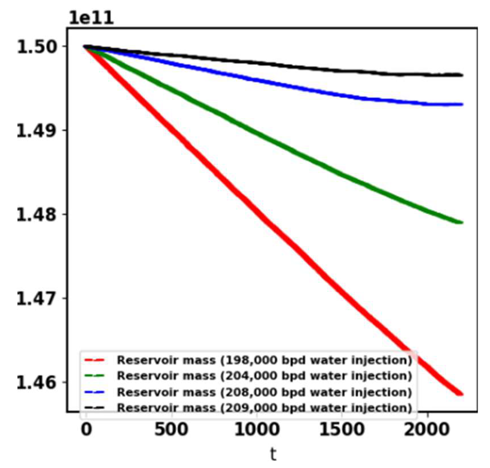
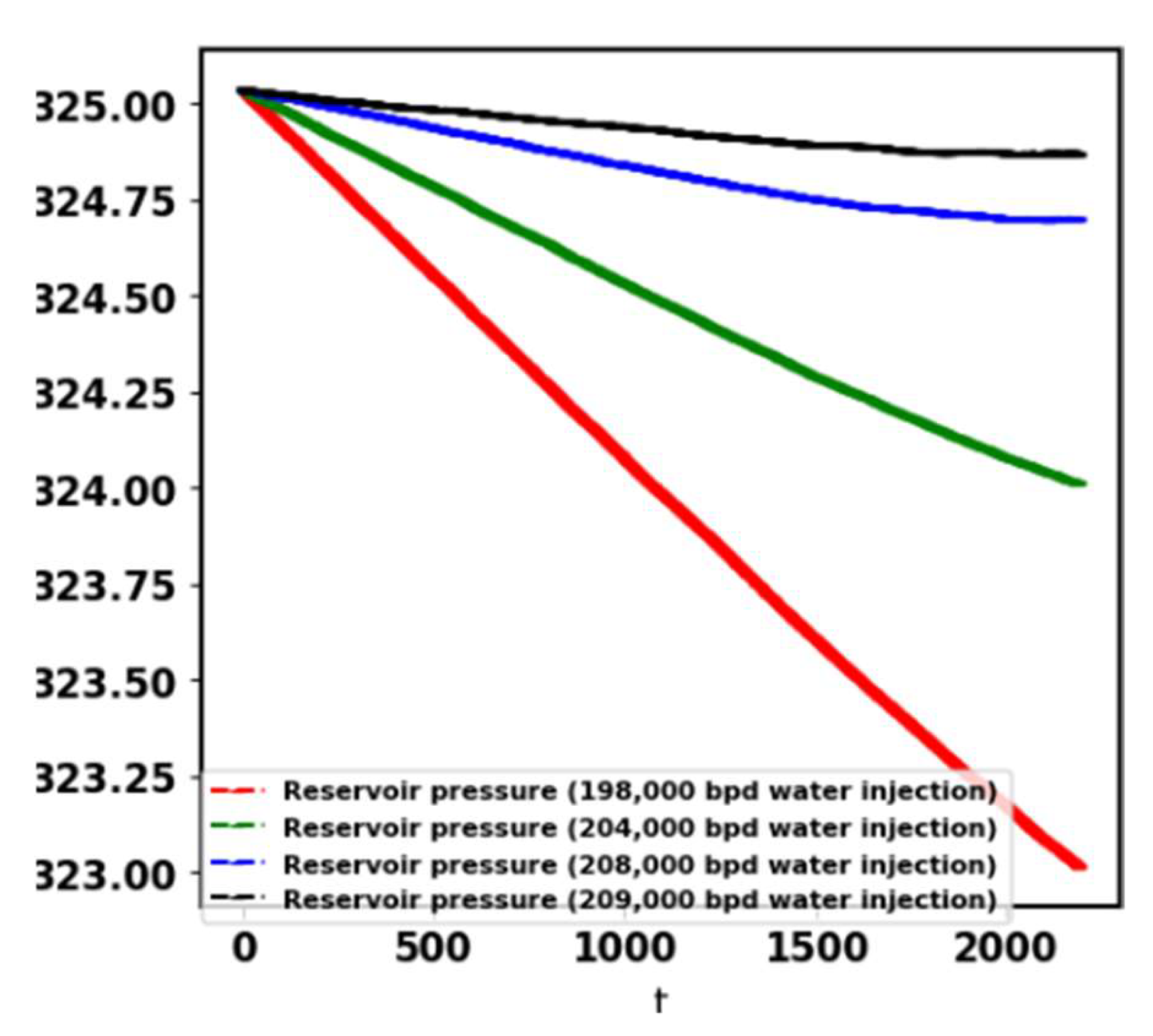
Figure 4.2.1.
Actual remaining reservoir exploitable mass for a 6-years planning horizon (mass balance solution).
Figure 4.2.1.
Actual remaining reservoir exploitable mass for a 6-years planning horizon (mass balance solution).
Figure 4.2.2.
Estimated reservoir pressure for a 6-years planning horizon.
4.3. Case Example: MPC Automation using the MPC's Objective Function
The objective of using the MPC is to avoid equipment trips while maximizing production or to attenuate the plant variability using together with regulatory controllers subject to the constraints. The short-term MPC is interesting because it is a class of problem solved aside from the scheduling. Either must be decided to use the scheduling model or the MPC. Scheduling is better to use when one wants to create decision-making for supply chain offloading and inventory routing (supply problems) or because one wants to have more chance to find a more profitable solution, while the short-term MPC is better used when one wants to have more short-term control while maximizing oil production subject to short-term challenges.
One must be aware that scheduling production generally can concede bigger production because to control oil production or other variable(s), the constant or almost constant controlled variable(s) can be placed in a condition far from the upper bound to satisfy all constraints while maintaining a steady control (MPC's functionality). The scheduling differential is that it creates conditions to maximize production while not caring about limiting the amount of oil or the overall mass flow that enters in the platform to maintain constant. Therefore, it is likely to see scheduling being more profitable but harder than the MPC to be put into practice, needing a prepared team to reschedule over periods if needed to update estimates, while the short-term MPC is likely to give a more smooth and automatic production. The MPC does not account for supply chain studies because they generally have inventory being controlled and routing on a daily basis.
All considered disturbances can be measured by sensors, directly or indirectly with a calculation/conversion in the plant. Through a pressure transmitter, the upstream pressure of the topside choke valve can be measured and the signal can be given to the DCS or other independent central to calculate what are the feeding chemical compositions that links to this value. In the DCS, for example, a predictor will calculate or estimate future values for the inputs, and the algorithm will optimize the decision-making through the present model. The procedure to automatic control system override of the present model applied to short-term MPC is to have the last values of all involved parameters in real-time optimization stored in the memory of the computer central, and then calculate the future decision-making starting with these stored values.
is specified for the MPC simulation, and and are calculated variables. Since is measured by an instrument, it does not have to be calculated in the DCS and is here generated by a normal distribution for simulation purposes. Table 4.3.1 shows the description of the MPC problem.
In the automatic MPC that is based in seconds, group of seconds or minutes, the model is the same, but modeling in DCS or PLC must have a continuous version without accounting for offloading (for short-term automation) for real-time and short-term solving with connection to sensors. The composition ratio GOR (gas-oil ratio) was considered as a disturbance just as in the scheduling to show the efficiency of the automatic MPC. The uncertain inputs, and the manipulated and controlled variables are shown in Table 4.3.1. The correspondent plots are shown in Figure 4.3.1 – 4.3.2. The objective function of the MPC is Eq. 3.2C with its attached constraints. The present section considers two different optimizations for the MPC short-term application, the first considering for oil maximization reconciling with process control, and the second considering for a process control more susceptible to stability without worrying about oil maximization (higher available degree of freedom).
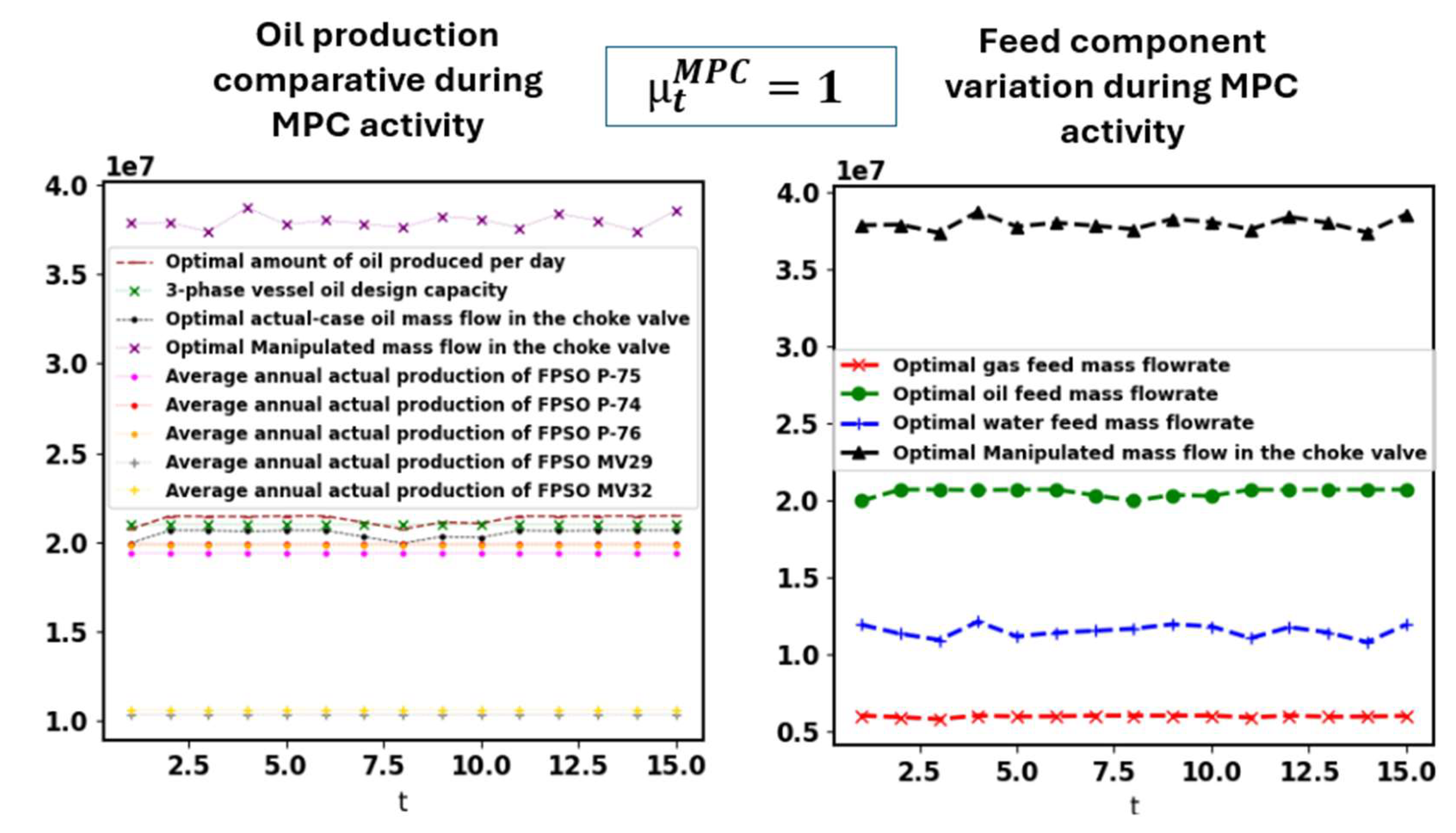
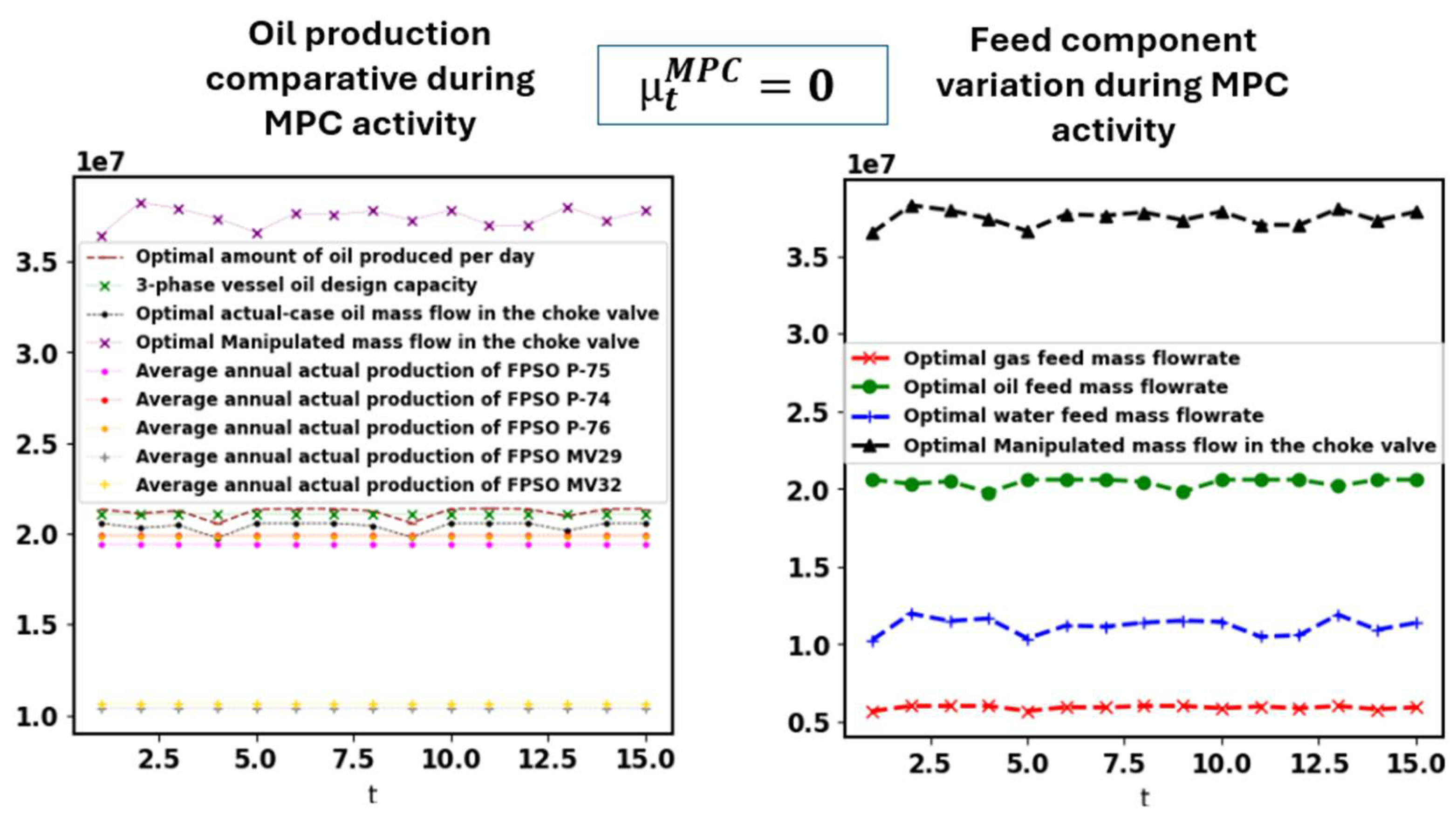
Figure 4.3.1.
Production for the topside choke valve for and .
Figure 4.3.2.
Production for the topside choke valve for and .
10 simulations were performed for each to the same inputs from the section 4.1 and were compared to the same FPSOs. When is 0, the LMP-MPC had an average increase in production during campaign around 5.5%, and 57% on a start-up after first oil. When is 1, the LMP-MPC had an average increase in production during campaign around 9.56%, and 99.6% on a start-up after first oil, against the 10.5% and 101.5% for the scheduling presented in section 4.1. Scheduling gives a bigger production because of its priority of maximizing production without caring about if any variable is smoothly controlled if not determined by Eq. 3.7.30. All the model's variables work together as a whole, but of course influences directly and is the most sensitive variable for production. Other kind of appreciated short-term MPC in the platform would be controlling, with Eq. 3.2C, the amount of burned gas to generate electricity to make production smooth and feasible in a field with high contents of CO2 (up to 75% of the gas composition) while maximizing oil subject to constraints. For different MPC purposes, the sensitivity of the variables would be different depending on the purpose, and some would have more influence in controlling the required setpoint, whenever different inputs are inserted, than others.
The run-time for ordinary computers is not more than 1 second when running the MPC in a high-level programming language for 15-time units as a short-term planning horizon. Meaning that for example, for predicting future actions, it would have like more than 14 discrete times forward as a slack in operational timeline to run the MPC again to provide all new actions/anticipations (the decision-making). As DCS and PLC are generally working with fast programming languages, this slack would be bigger, and with smaller run-time. There is not any binary variable precluding implementation of the MPC in DCS because all of them can be put as integers/inputs providing a continuous linear program.
There is a benefit of having a permanent downhole gauge available for the MPC considering subsea variables. If a PDG for pressure measurement in real-time for the tubing is available, then can be an input in the MPC. This will ensure for the short-term MPC that variables are calculated more precisely since rigorous value is calculated through nonlinear equations. Moreover, knowing opens new model settings, e.g., specifying to calculate or better compute linearly the pressure drop calculation etc. As the section 3.12 is optional, a short-term MPC can also consider subsea variables without worrying about subsea pressure and considering only upstream pressure right before the topside choke valve, seen that this pressure can also be measured in practice. Oil platforms have an MPFM (multiphase flow meter) before the topside choke valve and using the MPC or the scheduling can give setting to compare the optimal flow to that one being measured. If well calibrated and without issues, measuring shall be optimal.
4.4. Dynamics
The MPC-based scheduling is less robust than the ordinary scheduling because establishing static setpoints to maximize oil while coping with dynamics, uncertainties and inventory control is more difficult, as optimal domain values could lie out of the available bounds subjected to the constraints. Finding an average to an uncertainty problem is more difficult than accepting the uncertainties and acting accordingly. MPC-based scheduling is prone to work better in some inputs while other is favorable to work better with a simple scheduling avoiding averages in decision-making variables. On the other hand, it is easier to handle static setpoints or multiple static setpoints in-plant while producing in the routine because manual override can be done, but not recommended of course. The dynamic setpoints need an automatic setup and are recommended for process safety. The automatic MPC based in seconds is robust as its objective is not really to generate static setpoints.
The dynamic changes when using different settings for the objective function and model, e.g., Figure 4.4.1 shows a visualization of how gas inventory varies during the use of the MPC for a start-up simulation case considering 100-time units (or the day after offloading is done which starts with an initial inventory). As can be seen, Figure 4.4.1 is different than Figure 4.1.4, and is smoother because any MPC is a short-term application and because of this is not made to compute offloading as it lasts for hours of operation during a day. This can be seen as a drawback compared to the scheduling, i.e., decision-making for oil and gas supply chains (e.g., inventory routing and scheduling for delivery) works better when using scheduling approaches. The actual MPC can be put online to data reconciliation for overwriting the oil and gas inventory values whenever an offloading occurs, just for monitoring purposes (which can be easily done in practice), so if an offloading occurs the system will not need to be restarted seen that the MPC is dynamic.
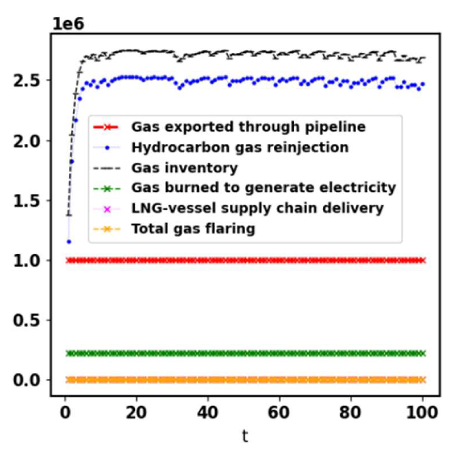
Figure 4.4.1.
Gas inventory visualization from a simulation of a start-up scenario or after offloading is done of the LMP-MPC considering 100-time units.
Figure 4.4.1.
Gas inventory visualization from a simulation of a start-up scenario or after offloading is done of the LMP-MPC considering 100-time units.
The bigger are , pressure drop and , the bigger must be the ratio between gas and oil or lesser must be the amount of the hydrocarbon gases burning, storage and liquid recovery. The last option is not feasible in practice, neither economically nor functionally. Moreover, if is lesser specified, the model forces to inject more . makes more sense on onshore applications.
Whenever the user wants to solve nonlinearity, as the problem has just a few binary variables, it is possible to turn them into continuous variables instead and strangle them with big-M constraints to solve an NLP instead of an MINLP setting. The MINLP can give the same result as the MILP, mainly if the nonlinearity comes from simple parameters turned into variables just as or the amount of recycling gas in sector f, etc., but the MILP is way easier and faster to solve and converge.
Instability during some days in the planning can be completely normal because of , inventory initial conditions, boundary conditions (e.g., supply chain demand) and stipulated controllability. If the model starts with empty inventories, and controllability is not set, then higher variabilities could be encountered (higher dynamics). For example, water in the lung tank can be not constant because if the model starts the optimization with an empty inventory, or even with a different value other than the water setpoint, it will work as a disturbance to the model (like as in a servo regulatory control capacity). It can be avoided using the MPC-based scheduling. If the water lung tank had no output variable as the oil and gas tanks, there would have been no disturbances since would have a monotonic fill just as in oil production and storage. works as a slack variable to control the inventory, and the value of creates the initial variability on its value, starting with lesser values in the first days as the empty tank holds more space and there is no need to discharge to the sea, unless one put a tight inventory or a considerably big initial inventory minimum capacity.
and are precisely minimized by the model. An example of how integrative is the model: in decision-making, , , and are in-plant manipulated variables, and can be done by PID controllers or by a hybrid decision-making, either totally or partially predictive move.
4.4.1. Uncertainty and Robustness
For short-term planning horizons, computational effort is insignificant, i.e., optimization under uncertainty can be applied with different techniques such as robust optimization, or stochastic programming without being worried about time. In the present paper uncertainties were treated as stochastic inputs just as in practice. The model is robust by itself, therefore no penalization method like a robust optimization technique was needed to represent uncertainty. Stochastic programming is recommended whenever one wants to find an average solution, but this kind of optimization problem represents reality when considering the actual current producing capacity and real-time composition, which were the inputs considered.
For long-term running, computational effort is significantly a matter if the binary variables are considered for optimization. For decreasing computational effort and time response for decision-making, in this case, one just needs to consider and substitute the binary variables to integer values as being wished for decision-making.
Stochastic programming and robust optimization have been widely used in supply chain inventory routing planning and scheduling models, and as an example of success, they usually have way more constraints to be solved. For the present model, optimization under uncertainty is not a problem considering that the model solves with faster time and compared to supply chain problems, it has way lesser number of variables and constraints.
4.5. Potential and Limitations
The present model was extremely robust, with high performance and speed. It serves for production scheduling for any planning horizon and is a constrained optimization problem focused on oil maximization subject to sustainable, operational, and regulatory aspects. Even when the set of time units are populated in seconds, group of seconds or minutes, it works as an MPC to control any variables established in its scope according to the user chosen setting, an example is the fluid flow control to stabilize the oil mass flow in the choke valves. It also includes other features such as: reservoir pressure monitoring and subsea flow assurance; clearly defining how the topside and subsea equipment/valves should operate to maximize oil production and enable production; the minimum necessary electricity generation and gas lift; gas and water reinjection; gas and water inventory control; and oil and gas offloading to supply chain.
The present model can be used for the optimal planning and scheduling of an FPSO already under operation or for CAPEX investment analysis, or to design new FPSOs for new potential reservoir/wells, or to control production smoothly. Oil production is maximized while satisfying sustainability, operability and reservoir/well(s) revitalization constraints. The present article brings a model to provide optimization of oil production on offshore or onshore oil platforms dealing with multiphase flow (subsea and topside) with reservoirs having oil, gas, and water, especially FPSOs. The program maximizes oil production and determines how the oil platform must operate and manipulate the topside and subsea equipment/valves. The model includes constraints for which the user can assemble to control the quality and dynamics of the results for all product variables. The model provides the setpoints as decision-making to the management put into the DCS to maximize oil production with automation. Moreover, short-term automation is also possible either using the scheduling setting or using the proposed MPC. The model is by its nature a maximizer of oil and production controller since controllability constraints were inserted. The model is also capable of handling rigorous plant start-ups or shutdowns. Dynamics are very well controlled, and stability is achieved even starting with empty inventories.
Typically, a choke valve has the inability to precisely control pressure and/or flow, especially when the trim gets worn out with time. Using the present research, one can know the safety and optimal setpoint or opening percentage/mass flow values for the choke valves over a planning horizon, as well as manage to operate it manually through gain scheduling or static manual override over a planning horizon.
Monitoring reservoir pressure or the reservoir mass content and amount is important for integrity aspects and production lifespan monitoring, and the model track this important asset. These features can also be used to analyze how long a reservoir is economically worthy to be or keep exploiting or whether is necessary to use a subsea pumping system. Pressure constraints are also helpful in operational decision-making. If it is wanted to monitor the reservoir exploitable mass and CAPEX, instead of reservoir pressure, all optional pressure constraints do not need to be included in the model. Including optional pressure constraints to predict reservoir pressure is an excellent form of knowing the operational pressure health for commercial lifespan prediction.
The model presents alternatives such as the use of renewable energy, and integration of steam for gas lift, hot water, and CO2/CO injection for carbon capture planning and sustainability, wherein a full modern platform should have this module, mainly when exporting gas to buyers. For attaining more platform sustainability, energetic independence and environmental purposes, the model integrates the possibility to reinject all produced CO2/CO, fruit of burning production gases to generate electricity or steam, into the injection well(s). For sustainable philosophy, it is being proposed the possibility to also reinject produced CO2/CO just as the own produced CO2 that comes into the topside choke valve from the producer well(s). Other environmental contributions of the model are the minimization of disposal of excess water overboard as environmental agencies allow, planning water and gas injection, and precluding burning unnecessary amounts of gases in the flares that happens when not reconciling inventory control and operation. The production scheduling creates a work environment that is for itself a friend of sustainability as it organizes production to avoid undesired uncertainties and unpredictable decisions.
The present either linear or nonlinear setting can provide real-time decision-making for complex decisions in subsea side in what refers to well revitalization, injecting gas and water. Converting the optimized pressure value to a signal to either topside or subsea actuators can optimize the wells' lifespan by increasing to a pressure that does not prejudice production at the same time optimal oil is lifted to be produced. The entire model has complex decision-making calculations but, in the end, translate platform possibilities to easy decision-making reflected on electricity production, electricity use, PVT settings and flow manipulation. The present model details PVT and flow profiles along a planning horizon. For this, material and energy balances were solved, and efficiency integration constraints were added all along the model.
An oil and gas business must economically decide whether to totally or partially reinject the gas. The number of LNG tankers worldwide is increasing as per 2022 there were more than 734 vessels (Statista, 2024). Some FPSOs in the world do not export gas either because of a lack in pipeline infrastructure or because inventory routing and CAPEX/OPEX for cargo tanker exportation is not profitable enough. The present model also creates scheduling and organization to provide this kind of complex decision-making reconciling with supply chain demand and can be integrated into oil and LNG supply chains. Countries that depend on electricity generation through gas dependence like, e.g., Singapore, or other isolated countries, can use the present model to try to develop or enable the national industrial scenario through an economic study of LNG supply through LNG tanker ships. The present model can also be used for novel CAPEX-design decision using multiple FPSOs to produce over a reservoir, and this is made by simple multiplying the upper and lower bounds of equipment/nodes to provide a simulation/optimization of the scenario as being a one bigger FPSO.
The present article discloses a novel model tackling challenges and proposing new strategies to improve the modus operandi in oil facilities. Classical production was approached and improved to a profitable and sustainable scheduling level. The model is concrete and intelligent, it describes how to operate the plant in a minimal way to attain important results and variables specifications, providing the best feasible solution. The model focuses on practice and is not interested in complex and intractable decision-making; thus, it compiles a gathering between mechanistic laws, constitutive math, and data science.
Smart production can be done when optimally scheduling decision-making including sustainability and profitability. In the practical point of view in about using the present plantwide MPC is that it is affordable to tune it while currently running the plant, and a trial and error or a grid search method can optimize it. Once it is tuned in for the first time, production changes will be minor as the oil supply chain generally demands maximum platform capacity. Strengths of the model are that: before deploying the MPC, the oil platform can be already operating under the same model but as a scheduling; and the model uses intelligent insights to provide robust and efficient linear calculation to nonlinear phenomena without appeal to approximations. The way the model was created serves as a paradigm for the creation of other models that relate data, MPC or thermodynamics principles to real and large-scale physical systems.
The subsea modeling discussed in section 3.12 can be adapted for what the user better understands as the subsea facility in which wants to deploy the model. The present article brings a general structure that was created with the intention to be used to any subsea but is not a specific structure that must mandatorily be used. Despite the supply chain being approached with a general structure, the author intends to further connect a general supply chain inventory routing model for oil or LNG supply chains. The present model can be connected to two different supply chain models, one for the LNG and the other for the oil supply chain. The strength of this strategy is to create a more robust model against uncertainty. It can be done without loss of generality since the model generates the offloading demand at the day inventory routing is set to happen.
Production scheduling is important to determine whether production is feasible due to a change in inputs and operational bounds, and to dynamically monitor the inventory prediction. Optimal scheduling is granted when using the present model. The present paper shows a mathematical model to improve profit, reduce costs, reach a more sustainable production, and process safety in the oil platform through an organized production planning and operational scheduling. For a more realistic reservoir pressure prediction, nonlinear constraints must be considered and possible empirical equations as well. On the other hand, it was shown that the linear approach for handling this prediction is a good, fine-tuned methodology as oil is instilled produced. Regarding reservoir mass content monitoring and manipulation through injection, there is no need to non-linearize the model. Afterwards, minimal change in the model to adapt to oil platforms can be performed if needed, but all essential unit operations that can affect oil, gas and water variables were comprised.
The present model is not recommended for the first oil production's start-up since the equipment is not pressurized yet and because there are many contaminants and uncertainties that can halt operation, as well as because in this case off-spec tanks are used and were not modelled in the model. Another limitation is that the present model was not modeled to account for clogged systems (undesired uncertainty) or intermittent actions while cleaning it. However, in an optimal routine procedure, this is unlikely to be seen because of standard routine clean-up procedures of strainers etc. Ordinary obstructions and fluid flow regime can be represented or estimated when predicting the inputs' uncertainties like compositions and initial subsea production capacity under plant design (of the planning horizon) for each component. If the regime is well estimated, the scheduling can better represent reality but one may note that generally there are subsea equipment made to attenuate slug, therefore the probable regimes are churn flow or annular, and one must keep it in mind when treating feed uncertainties. The MPC is more blinded against the need to estimate fluid flow regime.
It is more productive to not depend on different humans when setting the setpoints, and either they must be set each day or once per planning. The appropriate way may be automatic scheduling with computer setting to change the values in accordance with each day's decision-making plan. This is important because depending on the strategy used, some decision-making will generate dynamic setpoints (gain scheduling), while others will generate totally or partial static setpoints (multiple static setpoints over a planning horizon). Finally, if a unit trip occurs due to mechanical failure, lack of maintenance, or other reason, a rescheduling is needed, either manually or reactive scheduling. In the case of the MPC, then a manual restart is recommended.
5. Conclusions
The oil industry faces maturation of wells and reservoirs, reducing its producible oil quantity. To overcome this problem, at the same time profit is being maximized and attended with sustainability as its best, a production scheduling model or a plantwide MPC is needed to make production feasible and stable over specified bounds. The present article provided a novel topside and subsea planning and production scheduling model and a generic plantwide MPC production maximizer (LMP-MPC) regarding oil, gas, and water operations. Peculiarities, pros, and cons of the present research were discussed.
The priority was an LP/MIP to optimize large-scale oil and gas production in an oil platform and reconcile sustainability, operation constraints, heat and mass balances, thermal efficiency, flow assurance and capacities, and reservoir/wells revitalization. The present model defines setpoints and decisions that must be made for the equipment, valves and supply chain in topside and subsea to optimize profitability by production estimation or composition of oil, gas and water of the wells. With the present model is possible to determine decision-making for a current actual production, or to develop process design, and conclude if the planning and scheduling offshore or onshore operation is either optimal or infeasible for a set of inputs for short-, medium- or long-term operation. A strength of the model is that it does not suppress feedback controllers, and if used as MPC, is recommended to use both at the same time for process safety. The model can integrate supply chain inventory routing models and other subsea approaches. Without a production scheduling model, an optimization over the production planning is unlikely possible to be made because, with so many uncertainties, not knowing what happens through the production makes it harder to link the variables' inventory control and supply chain management to the optimal operation.
The present model proportionated the following aspects: 1) one can consider optimizing focusing on the reconciliation between production maximization and process control, or 2) can give priority to make the degree of freedom focus on process control. The present model serves to be used when the facility is already constructed and operating, but also serves engineering, procurement, construction and installation services on the project phase to determine optimal design. Since the present model is flexible and a MILP/MINLP can become either LP or NLP, a linear/nonlinear extension is to be published in another paper as a continuation focused on inventory capacitated routing problem. The present model focused on linear approach to grant robustness as its best. The present model can be integrated to other subsea models regarding pressure constraints, and when treating scheduling, an LNG supply chain inventory routing problem, as well as that one of oil supply chain can be integrated.
Acknowledgments
The research leading to this paper was funded by Petróleo Brasileiro S.A. (Petrobras) under grant 23078.000116/2020-01.
References
- Aske, E. M. B., Strand, S., & Skogestad, S. (2008). Coordinator MPC for maximizing plant throughput. Computers & Chemical Engineering, 32(1-2), 195-204. [CrossRef]
- Assis, L. S., & Camponogara, E. (2016). A MILP model for planning the trips of dynamic positioned tankers with variable travel time. Transportation Research Part E: Logistics and Transportation Review, 93, 372-388.
- Assis, L. S., Camponogara, E., Menezes, B. C., & Grossmann, I. E. (2019). An MINLP formulation for integrating the operational management of crude oil supply. Computers & Chemical Engineering, 123, 110-125. [CrossRef]
- Assis, L. S., Camponogara, E., & Grossmann, I. E. (2021). A MILP-based clustering strategy for integrating the operational management of crude oil supply. Computers & Chemical Engineering, 145, 107161. [CrossRef]
- Baldea, M., & Harjunkoski, I. (2014). Integrated production scheduling and process control: A systematic review. Computers & Chemical Engineering, 71, 377-390. [CrossRef]
- Barbosa Filho, A. C. B., & da Silva Neiro, S. M. (2022). Fine-tuned robust optimization: Attaining robustness and targeting ideality. Computers & Industrial Engineering, 165, 107890. [CrossRef]
- Bidgoli, A. A. (2018). Simulation and optimization of primary oil and gas processing plant of FPSO operating in pre-salt oil field (Doctoral dissertation, Universidade de São Paulo).
- .
- Carvalho, M. C. A., & Pinto, J. M. (2006). A bilevel decomposition technique for the optimal planning of offshore platforms. Brazilian Journal of Chemical Engineering, 23, 67-82. [CrossRef]
- Carvalho, M. C. A., & Pinto, J. M. (2006). An MILP model and solution technique for the planning of infrastructure in offshore oilfields. Journal of Petroleum Science and Engineering, 51(1-2), 97-110. [CrossRef]
- Cho, Y., Kwon, S., & Hwang, S. (2018). A new approach to developing a conceptual topside process design for an offshore platform. Korean Journal of Chemical Engineering, 35, 20-33. [CrossRef]
- Dan, S., Shin, D., & Yoon, E. S. (2015). Layout optimization of LNG-liquefaction process on LNG-FPSO preventing domino effects. Journal of chemical engineering of Japan, 48(8), 646-655. [CrossRef]
- Epelle, E. I., & Gerogiorgis, D. I. (2020). A computational performance comparison of MILP vs. MINLP formulations for oil production optimisation. Computers & Chemical Engineering, 140, 106903. [CrossRef]
- Fath, A. H., & Pouranfard, A. R. (2014). Evaluation of miscible and immiscible CO2 injection in one of the Iranian oil fields. Egyptian Journal of Petroleum, 23(3), 255-270. [CrossRef]
- Foss, B., Knudsen, B. R., & Grimstad, B. (2018). Petroleum production optimization–a static or dynamic problem?. Computers & Chemical Engineering, 114, 245-253. [CrossRef]
- Gao, X., Xie, Y., Wang, S., Wu, M., Wang, Y., Tan, C., ... & Chen, T. (2020). Offshore oil production planning optimization: An MINLP model considering well operation and flow assurance. Computers & Chemical Engineering, 133, 106674. [CrossRef]
- GNU Project. GLPK (GNU Linear Programming Kit). https://www.gnu.org/software/glpk/, 2012.
- Gupta, V., & Grossmann, I. E. (2012). An efficient multiperiod MINLP model for optimal planning of offshore oil and gas field infrastructure. Industrial & Engineering Chemistry Research, 51(19), 6823-6840. [CrossRef]
- Gyllenhammar, E., Duvall, S., & Gabelloni, M. (2017, May). Combining FPSO and Subsea Processing for Optimized Field Development. In Offshore Technology Conference. OnePetro.
- Hart, William E., Jean-Paul Watson, and David L. Woodruff. "Pyomo: modeling and solving mathematical programs in Python." Mathematical Programming Computation 3(3) (2011): 219-260.
- Hasan, A., & Foss, B. (2013, July). Optimal wells scheduling of a petroleum reservoir. In 2013 European control conference (ECC) (pp. 1095-1100). IEEE.
- Hülse, E. O., Silva, T. L., Camponogara, E., Rosa, V. R., Vieira, B. F., & Teixeira, A. F. (2020). Introducing approximate well dynamics into production optimization for operations scheduling. Computers & Chemical Engineering, 136, 106773. [CrossRef]
- Hwang, J. H., Roh, M. I., & Lee, K. Y. (2013). Determination of the optimal operating conditions of the dual mixed refrigerant cycle for the LNG FPSO topside liquefaction process. Computers & Chemical Engineering, 49, 25-36. [CrossRef]
- IEA (2023), World Energy Outlook 2023, IEA, Paris https://www.iea.org/reports/world-energy-outlook-2023, Licence: CC BY 4.0 (report); CC BY NC SA 4.0 (Annex A).
- Iyer, R. R., Grossmann, I. E., Vasantharajan, S., & Cullick, A. S. (1998). Optimal planning and scheduling of offshore oil field infrastructure investment and operations. Industrial & Engineering Chemistry Research, 37(4), 1380-1397. [CrossRef]
- Jahanshahi, E., & Skogestad, S. (2017). Nonlinear control solutions to prevent slugging flow in offshore oil production. Journal of Process Control, 54, 138-151. [CrossRef]
- Jeong, S. Y., Roh, M. I., & Shin, H. (2015). Multi-floor layout model for topsides of floating offshore plant using the optimization technique. Journal of the Society of Naval Architects of Korea, 52(1), 77-87. [CrossRef]
- Kim, S. K., Roh, M. I., & Kim, K. S. (2017). Arrangement method of offshore topside based on an expert system and optimization technique. Journal of Offshore Mechanics and Arctic Engineering, 139(2). [CrossRef]
- Ku, N., Jeong, S. Y., Roh, M. I., Shin, H. K., Ha, S., & Hong, J. W. (2014b, June). Layout method of a FPSO (Floating, Production, Storage, and Off-loading unit) using the optimization technique. In International Conference on Offshore Mechanics and Arctic Engineering (Vol. 45387, p. V01BT01A032). American Society of Mechanical Engineers.
- Ku, N. K., Hwang, J. H., Lee, J. C., Roh, M. I., & Lee, K. Y. (2014a). Optimal module layout for a generic offshore LNG liquefaction process of LNG-FPSO. Ships and Offshore Structures, 9(3), 311-332. [CrossRef]
- Lee, S., & Grossmann, I. E. (2000). New algorithms for nonlinear generalized disjunctive programming. Computers & Chemical Engineering, 24(9-10), 2125-2141. [CrossRef]
- Mardaneh, E., Loxton, R., Lin, Q., & Schmidli, P. (2017). A mixed-integer linear programming model for optimal vessel scheduling in offshore oil and gas operations. Journal of Industrial & Management Optimization, 13(4), 1601. [CrossRef]
- Moolya, A., Rodríguez-Martínez, A., & Grossmann, I. E. (2022). Optimal producer well placement and multiperiod production scheduling using surrogate modeling. Computers & Chemical Engineering, 165, 107941. [CrossRef]
- Neiro, S. M., & Pinto, J. M. (2004). A general modeling framework for the operational planning of petroleum supply chains. Computers & Chemical Engineering, 28(6-7), 871-896. [CrossRef]
- Park, K., Koo, J., Shin, D., Lee, C. J., & Yoon, E. S. (2011). Optimal multi-floor plant layout with consideration of safety distance based on mathematical programming and modified consequence analysis. Korean Journal of Chemical Engineering, 28, 1009-1018. [CrossRef]
- Patsiatzis, D. I., & Papageorgiou, L. G. (2002). Optimal multi-floor process plant layout. Computers & Chemical Engineering, 26(4-5), 575-583. [CrossRef]
- Pereira, L. A. G., & Yanagihara, J. I. (2022). Sensitivity analysis and optimization to reduce dry weight and footprint of FPSO processing plants in a high CO2 oil field. Computers & Chemical Engineering, 156, 107576. [CrossRef]
- Reis, M. M. L., & Gallo, W. L. (2018). Study of waste heat recovery potential and optimization of the power production by an organic Rankine cycle in an FPSO unit. Energy Conversion and Management, 157, 409-422. [CrossRef]
- Sehgal, C., & Khan, M. Z. (2020, November). Fpso 4.0: Powering deepwater production and optimizing the lifecycle performance of offshore rotating equipment packages. In Abu Dhabi International Petroleum Exhibition & Conference. OnePetro.
- Souza, M. V., De Lima, B. S. L. P., & Baioco, J. S. (2019). Process plant layout optimization of an FPSO. IEEE Latin America Transactions, 17(10), 1724-1732.
- Stanzani, A. D. L., Pureza, V., Morabito, R., Silva, B. J. V. D., Yamashita, D., & Ribas, P. C. (2018). Optimizing multiship routing and scheduling with constraints on inventory levels in a Brazilian oil company. International Transactions in Operational Research, 25(4), 1163-1198. [CrossRef]
- Statista Research Department. (2024). Statista. Global fleet of LNG tankers 2010-2022. https://www.statista.com/statistics/468412/global-lng-tanker-fleet/.
- Tapia, J. F. D., Lee, J. Y., Ooi, R. E., Foo, D. C., & Tan, R. R. (2016). Optimal CO2 allocation and scheduling in enhanced oil recovery (EOR) operations. Applied energy, 184, 337-345. [CrossRef]
- Trica, D. J. (2022). Dynamic modeling of a topside process plant with modified black-oil approach. Journal of Petroleum Science and Engineering, 212, 110316. [CrossRef]
- Tsarbopoulou, C. (2000). Optimisation of Oil Facilities and Oil Production, M.Sc. Dissertation, University College London (UCL), London, UK.
- Veloso, T. G. C., Sotomonte, C. A. R., Coronado, C. J., & Nascimento, M. A. (2018). Multi-objective optimization and exergetic analysis of a low-grade waste heat recovery ORC application on a Brazilian FPSO. Energy Conversion and Management, 174, 537-551. [CrossRef]
- Verheyleweghen, A., & Jäschke, J. (2018). Oil production optimization of several wells subject to choke degradation. IFAC-PapersOnLine, 51(8), 1-6. [CrossRef]
- Wang, Y., Estefen, S. F., Lourenço, M. I., & Hong, C. (2019). Optimal design and scheduling for offshore oil-field development. Computers & Chemical Engineering, 123, 300-316. [CrossRef]
- Willersrud, A., Imsland, L., Hauger, S. O., & Kittilsen, P. (2013). Short-term production optimization of offshore oil and gas production using nonlinear model predictive control. Journal of Process Control, 23(2), 215-223. [CrossRef]
- Zhang, A., Zhang, H., Qadrdan, M., Yang, W., Jin, X., & Wu, J. (2019). Optimal planning of integrated energy systems for offshore oil extraction and processing platforms. Energies, 12(4), 756. [CrossRef]
Disclaimer/Publisher’s Note: The statements, opinions and data contained in all publications are solely those of the individual author(s) and contributor(s) and not of MDPI and/or the editor(s). MDPI and/or the editor(s) disclaim responsibility for any injury to people or property resulting from any ideas, methods, instructions or products referred to in the content. |
© 2024 by the authors. Licensee MDPI, Basel, Switzerland. This article is an open access article distributed under the terms and conditions of the Creative Commons Attribution (CC BY) license (http://creativecommons.org/licenses/by/4.0/).
Copyright: This open access article is published under a Creative Commons CC BY 4.0 license, which permit the free download, distribution, and reuse, provided that the author and preprint are cited in any reuse.


