
Submitted:
20 July 2023
Posted:
22 July 2023
You are already at the latest version
Abstract
Polyaniline or PANI is a conductive polymer (CPs) with flexibility in turning into conducting properties. The drawback is mainly in terms of limited mechanical properties improvement which attracted the interest in fabrication of PANI with other polymeric materials. PANI-PVL composites film was synthesized and fabricated in this work with chronological steps according to the objectives aligned in two different phases. The first phase determines the optimum parameters to synthesize nanosized PANI. The ideal initial molar ratio, r was 1, stirring speed of 600 rpm, purified by filtration, synthesis temperature of 25 oC, washed by dopant acid, acetone and distilled water. The usage of non-ionic surfactant, Triton X-100 (TX100) with 0.1 % concentration favours the formation of smaller particle size of PANI and good dispersibility compared to the usage of anionic sodium dodecyl sulphate (SDS). The synthesis of PANI in nanosized dimension has the potential to be applied for antimicrobial applications such as gloves and antimicrobial coating of frequent contact points in the near future.
Keywords:
PANI
; polymerization
; particle size
; dispersion
; characterization
1. Introduction
Polyaniline (PANI) is synthesized by chemical oxidative polymerization with the addition of surfactants. The oxidizing agent used was ammonium persulphate (APS) to polymerize aniline and surfactants like anionic sodium dodecyl sulphate (SDS) and non-ionic Triton X-100 (TX100) used to enhance the dispersibility of PANI aside from controlling the particle size of PANI. Colloidal and dispersion stability of PANI dispersions is a valuable detail to track the quality based on the homogeneity and thus produce a stable dispersion. Mixing this nanoparticle with host material such as latex have a broad range of beneficial applications such as hybrid antibacterial and conductive coating for textiles [1,2]. The utilization of nanoparticle-based technologies centre on opportunities to improve the efficiency and sustainability.
Conductive polymers (CPs) are organic materials with unique electrical and optical properties. They can be made using simple, affordable methods and assembled into structures with multiple functions [3]. There were five main types of CPs will be discussed including polyacetylene (PA), polythiophene (PT), polypyrrole (PPy), polyphenylene (PPP) and polyaniline (PANI) [4]. The conductive properties of these CPs attributed to the structure of the polymer backbone containing conjugated π system [5]. Prevulcanised latex (PVL) is a good choice for fabricating latex composite materials because it has good mechanical properties and can be stored for longer periods of time at ambient temperature [6].
Synthesis of PANI-based composites had attracted many researchers over the last few years due to possible new properties produced by the combination with other materials as template, host and substrate [7]. Selection of PANI offers good conductivity, antimicrobial properties, corrosion inhibitor and magnetic properties [8,9]. PANI-cellulose composites create a potential material to be used as antimicrobial textile in biomedical field [5]. Synthesis of PANI with metal oxides have been done by researchers and were usually intended to be employed as humidity sensors, biomedicine and antioxidant [10,11]. Several plastics were used to fabricate conductive composites with elasticity properties using PANI. These composites have several applications including chemical sensors, solar cells, capacitors, and stretchable electronic devices [12]. PANI was able to be mixed with other polymeric material like elastomers to overcome its lack in mechanical properties [13,14,15,16].
Chemical oxidative polymerization of PANI is the easiest approach in synthesizing PANI [17,18,19,20]. Most papers yield micron sized (µm) PANI synthesized via conventional chemical oxidative polymerization method which is not suitable for advanced nanotechnology applications [21,22,23,24]. The synthesis parameters affecting the properties of nanosized PANI produced in terms of the morphology and particle size [25,26,27,28]. The reviewal of particle size of PANI produced mostly determined using SEM analysis without considering the measurement via Dynamic Light Scattering (DLS) method [29,30]. The parameters of PANI polymerization discussed here include the initial molar ratio of aniline to APS or denoted as r, stirring speed in synthesis, synthesis temperature, purification method of PANI, washing method of PANI and the usage of different surfactants. PANI polymerized with secondary growth and irregularly shaped in the absence of surfactant as soft templates as well as morphological and particle size control [31,32,33]. Surfactant act as template in polymer synthesis and the polarity have an influence on the resulting polymers in terms of particle size. Jamdegni et al. revealed that usage of anionic SDS and non-ionic TX100 result in different size and shape of polymers [21]. Higher stability of dispersion of synthesized nickel nanoparticles was obtained in the presence of anionic SDS compared to the usage of cationic surfactant [34].
PANI powder is synthesized in this research using predefined parameters. The parameters monitored include the initial molar ratio of aniline to APS, stirring speed, temperature, purification method, washing method and surfactant effect. Optimized parameters were determined stage by stage of parameters according to the results of FTIR for the quality of PANI produced, smallest particle size of PANI with range at lower than 1 µm and good dispersions of colloids as no separation of phase observed. The outcome of this phase gives out optimum parameters to synthesize PANI powder.
PANI synthesized into nano dimension have beneficial impact where the surface to volume ratio is higher. There were three most explored methods could be used to fabricate PANI which are the uses of hard template, soft template, electropolymerization and electro spinning [21]. Among these option, chemical synthesis using soft template route is preferable and predominant approach also reported in many studies due to low cost and easy recovery of PANI [31,33,35]. Usage of soft template method is easy to apply for its easy purification of PANI, cheaper and efficient technique [32].
2. Methodology
2.1. Materials
Nanosized PANI synthesized through chemical oxidative polymerization with and without surfactant. List of chemicals used were summarized in Table 1. Prepared under acidic condition (0.2 M hydrochloric acid, HCl), with ammonium persulphate (APS) as oxidizing agent. Two types of surfactants were used which is anionic, sodium dodecyl sulphate (SDS) and non-ionic, Triton X-100 (TX100). 0.2 M HCl was prepared and acetone for sample washing. Prevulcanized latex (PVL) was used as the host material.
2.2. Synthesis of Nanosized PANI
Nanosized PANI synthesized through chemical oxidative polymerization with and without surfactant prepared under acidic condition (0.2 M hydrochloric acid, HCl) with APS as oxidizing agent. Two types of surfactants were used which is anionic SDS) and non-ionic TX100. 0.2 M HCl was prepared and acetone for sample washing. Potassium hydroxide (0.2 M) solution was used in adjusting the pH of PANI dispersion in distilled water for zeta potential analysis. The schematic diagram is illustrated in Figure 1.
2.3. Phase 1: Parameters of PANI Synthesis
Synthesis of PANI in nanosized has several parameters to be accounted for and will be stated further throughout this section. There were limited standardized method used to synthesize PANI nanoparticles as the optimal approaches varies depending on the intended application of PANI. Control of PANI particle size is also least defined where the methods are not well-suited for producing nanoparticles in colloidal size range. The precursor method used here was adapted from a report by J. Stejskal in 2002 in IUPAC technical report where PANI was prepared in standardized approach involving many institutions [36]. The reference sample retain a parameter condition as stated in Table 2 below.
2.3.1. Initial Molar Ratio of Aniline: APS (r)
The first parameter that must be considered was the reactants ratio involving aniline monomer and APS as polymerization initiator or oxidizing agent. Equal (0.2 M: 0.2 M) and higher (0.3 M: 0.1 M) r were chosen in synthesizing PANI. Produced PANI precipitate was filtered, washed repeatedly, dried and grinded to get the final product in powder form. The formulations were investigated by the yield of PANI and FTIR.
2.3.2. Stirring Speed
Different stirring speed or agitation intensity during synthesis was carried out to examine the outcome which accessed in terms of particle size of PANI produced. Two speeds were chosen which are 600 rpm and 1200 rpm.
2.3.3. Synthesis Temperature
The temperature during synthesis also have significance in the properties of PANI produced. Synthesis at low temperature (0 oC) is the most common approach in a few papers. Numerous other sources apply synthesis at ambient temperature condition or 25 oC [37,38]. Effective control of temperature was made by using minimal exposure to open area and insulated container for 0 oC condition while usage of water bath set at 25 oC. The effect in particle size will be discussed and studied in this work.
2.3.4. Purification Method
PANI was purified by two approaches which are vacuum filtration or heating. The comparison between the method were suggested by the convenience offered in terms of product lost, time and effort. Vacuum filtration used Buchner funnel and pump to promote vacuum condition forcing filtrate separation from PANI solution at room temperature. The heating method used to separate the solution from PANI synthesis via evaporation at temperature of 80 oC. Optimized method is determined by the outcome from FTIR of PANI and the particle size.
2.3.5. Washing Method
PANI was washed simultaneously during the filtration process where PANI was collected on the filter paper while the filtrate was collected in the flask. Substances used as the washing agent include 0.2 M HCl, 0.2 M methanol and 0.2 M acetone at three consecutive cycles. The amount of washing substances added was equal to the volume of PANI polymerization solution. Since the volume was 1.0 L, the amount of 0.2 M HCl used was also 1 L and repeated three times producing a total amount of 3.0 L and applied for the other washing substances mentioned. Excess distilled water used for final washing until the colour of filtrate is colourless. The order of washing substance is firstly by 0.2 M HCl, 0.2 M acetone and distilled water. The series then replaces acetone with 0.2 M methanol to investigate the significancy in PANI washing. Effectiveness of each substance in washing were monitored according to the FTIR of filtrate. The particle size of PANI at each washing stages were monitored further to investigate the effect of washing towards the particle size.
2.3.6. Surfactant in Synthesis
Surfactants (SDS and TX-100) were added in the reactor with concentration of 0.1% w/w. The solutions were then stirred for another 45 minutes to disperse the surfactant. Aniline and APS were then added dropwise simultaneously into the surfactant solution till the reaction mixture changes in colour from milky white to dark green. After the whole amount of reactant was used up, the reaction solution was left stirred for 24 hours to complete the polymerization reaction. The solution was then transferred into beaker and sealed with aluminium foil and left for another day. The process proceeds by filtering and washing in the same approach, stored and dried accordingly. The sample was grinded into powder form and stored in a Beatson bottle for further analysis. The procedure is repeated by using different concentrations of surfactant: 0.5% w/w, 1.0% w/w and 1.5% w/w.
2.4. Characterization of PANI Powders and Dispersion
2.4.1. Fourier Transform Infrared Spectroscopy (FTIR) of PANI
FTIR analysis is carried out to determine the functional group present in PANI powder and subjected to drying inside oven for 2 hours at 60 oC to remove any remaining moisture. Nicolet iS10 with attenuated total reflection used to confirm the presence of respective key characteristic of substance. The spectral range is from 400 to 4000 cm-1 and 2 cm-1 resolution at ambient condition. The data acquired will be recorded according to ASTM E168 in absorbance mode. Liquid samples such as PANI washing filtrate, 0.2 M acetone and HCl are analysed using a Perkin Elmer FTIR instrument.
2.4.1. Particle Size Analysis of PANI
The particle size of PANI powder were analysed using Zetasizer 2590. The concentration of sample prepared was 0.012 % in distilled water and inserted in specified cuvette at adequate level of approximately 1 mL. Optical parameters for PANI samples were elucidated at Table 3 as the substantial input for Zetasizer 2590. Measurements were taken in triplicate and immediately before the particles underwent sedimentation. Sonication of samples was carried out for 1 minute at 30 oC.
3. Results and discussion
3.1. Synthesis of PANI
PANI was synthesized via chemical oxidative polymerization due to the convenience in preparation and process as approached by many literatures [4,17,18,39]. The polymerization of PANI is carried out using aniline as the monomer, APS as the oxidizing agent and hydrochloric acid solution to produce high acidity media.
3.2. Determination of Initial Molar Ratio of Aniline: APS (r)
The initial molar ratio of aniline monomer to APS or denoted as r is one of the vital parameters to be considered in the polymerization of PANI [17,39]. Even though the ratio could be determined directly from the stochiometric equation of PANI polymerization reaction, adjustment to other conditions is often considered into account to obtain properties and more clarification on the significance of r. The concentration of HCl as reaction media was retained at 0.2 M with synthesis temperature (0 - 5 oC) in PANI polymerization as recommended in numerous research papers [40,41]. The stirring speed used was 800 rpm throughout the synthesis period. Comparison was made between equal and nonequal molar ratio where the equal initial molar ratio of aniline to APS or r = 1 produced by using 0.2 M aniline and 0.2 M APS while 0.3 M aniline and 0.1 M or r = 3 represents as nonequal formulation. Higher molar concentration of aniline was chosen as comparison target due to there is agreement in several literature claiming that advantageous properties is attainable such as optimized fibre morphology [42]. The produced PANI precipitates were filtered, washed repeatedly, dried, and ground to obtain the final product in powder form. The formulations were investigated by the yield of PANI and the FTIR spectra.
3.2.1. Yield of PANI
Table 4 represents the reaction yield for PANI where r = 1 shows high yield with value of 90.39 % contrastingly for r = 3 with notable drop to considerably low value of yield, 34.72%. This drop was expected since higher amount of aniline still presents in the reaction media whereas APS has been consumed forming limited amount of PANI [39]. Equal molar formulations yield better than nonequal molar suggests that the consumption of both reactants was used up simultaneously while termination occur for higher r as all the oxidants were used up [40]. The slight reduction of yield from equal molar formulation was due to possible losses mainly during purification of PANI where repeated cycle of washing and filtering method was applied. This result shows that r has a pronounced effect on the yield of PANI and the mode of synthesis will be preferable at r of 1.
3.2.2. FTIR of PANI with Equal and Nonequal Molar Ratio of Aniline: APS
FTIR spectra of PANI synthesized in equal and higher r is shown in Figure 2. The two peaks close by each other at 1494 cm-1 and 1584 cm-1 ascribed to the C=C stretching modes of benzenoid and quinoid rings in PANI chain, respectively [21]. Another PANI characteristic peak observed at 1132 cm-1 and 1296 cm-1 which reflect as charged amine structure between aromatic ring and C-N stretching vibrations of aromatic amines, respectively [43]. Peak at 806 cm-1 corresponds to the 1,4 disubstituted ring of quinoid ring. Strong peak at 573 cm-1 correspond to the sulphate counter ion of SDS which is present in r = 3. Peak at 714 cm-1 correspond to the wag vibration of N-H of aniline monomer [44]. In this formulation, PANI was formed in limited amount as relative to the limiting amount of APS and consequently leaving the unutilized aniline monomer.
Even though multiple times of washing was applied, these unreacted species will remain as part of the final product [21]. The absence of unfavourable constituents is a key factor in the high-quality PANI synthesis achieved by the r =1 formulation. This distinction in properties of PANI at alteration of r resulting in different properties of PANI as highlighted in FTIR analysis as well as the yield of PANI.
3.3. Stirring Speed of PANI Synthesis
The effect of stirring speed on the quality of PANI produced as well as the particles size were monitored at speed of 600 rpm and 1200 rpm. Agitation of reactants during reaction was important for the uniform distribution of substance and reduces possible agglomeration. The equal molar ratio of aniline to APS was maintained to determine the optimum stirring speed. The quality assurance of PANI produced was conducted using FTIR and the particle size distribution data.
3.3.1. Effect of Stirring Speed to FTIR
FTIR spectra of PANI synthesized with stirring speed of 600 rpm and 1200 rpm were illustrated in Figure 3. The double peak at 1586 cm-1 and 1420 cm-1 correspond to the benzenoid and quinoid rings C=C stretching modes, respectively. Peak at 1115 cm-1 indicates the presence of amine structure between aromatic ring while 871 cm-1 and 826 cm-1 corresponds to the 1,4 disubstituted ring of quinoid ring. The obvious assignment peaks of PANI were presence for both conditions and shows almost identical trend. The quality of PANI produced was not significantly affected by the alteration of stirring speed which only involves mechanically during the polymerization of PANI. Similar FTIR trend was produced by Kamarudin in 2021 where no obvious differences between PANI synthesized in different stirring speed [45].
3.2.2. Effect of Stirring Speed to the Particle Size Analysis
Alteration of stirring speed has shown that there is no significant effect toward the FTIR analysis. Similar agreements were also made by the supporting data of particle size analysis for both conditions as displayed in Figure 4 showing the volume of particle size distribution represented in particle diameter and the cumulative volume. Both samples show binomial distribution where at stirring speed of 600 rpm reveals 65% domination of large particle population while 1200 rpm speed with equal volume distribution between small and large particle populations.
There is no significant difference in terms of particle size when the stirring speed was altered during the synthesis of PANI. The particle diameter shows almost identical particle size for both smaller and larger particle populations as shown in Table 5 below. The selection of stirring speed is preferable at lower speed to reduce as much energy consumed and cost of utilities in synthesizing PANI.
3.4. Synthesis of PANI at Different Temperature
Synthesis of PANI was carried out in different temperatures which is at 0 oC and 25 oC. There was no usage of surfactants in the synthesis process due to the Krafft temperature factor that affect the performance of surfactants function ability. The micelles formation takes places at above of the Krafft temperature of SDS which is 25 oC and above [33]. Alteration was made at synthesis of PANI without surfactant to elucidate the effect in term of particle size. FTIR analysis is not carried out since the fingerprints of PANI synthesized at different temperature was identical [32].
3.4.1. Effect of Synthesis Temperature to the Particle Size Analysis
The particle size analysis of PANI synthesized at temperature of 0 oC and 25 oC is shown in Figure 5. The particle size of PANI synthesized at temperature 0 oC was 1131.30 nm and much larger compared to PANI synthesized at 25 oC with size of 835.03 nm. According to Aribowo in 2018, synthesizing PANI at lower temperature led to higher molecular weight and higher crystallinity of PANI [32]. Since the polymerization of PANI is exothermic, the period of the reaction will be longer at lower temperature and vice versa [46]. Holding at lower temperature resulting formation of large particles since increment of crystallinity will lead to an increase in crystallite size and hence an increase in particle size is expected [32,33]. PANI was then synthesized further at 25 °C because it resulted in smaller particle size, faster reaction time, suitable to implement SDS in polymerization and better temperature control than synthesizing at 0 °C. These advantages are important especially for larger-scale production of PANI.
3.5. Purification Method of PANI
PANI synthesized after 24 hours produces a solution containing PANI, unreacted reactant, oligomers and mostly solution of acidic HCl media. Purification of PANI was done via filtration or heating. The quality of PANI purified were dictated by FTIR as well as the particle size of PANI.
3.5.1. Effect of PANI Purification Method to FTIR
PANI The FTIR of PANI purified by filtration and heating is shown in Figure 6. Both spectra exhibit the characteristic peaks of PANI, but they differ notably in some shifting and absorbance intensities. The peak at 1494 cm-1 showed an increased intensity indicating higher quinoid structure upon heating [43]. Higher intensity was also observed at 1296 cm-1, while reduction was identified at 806 cm-1. PANI purified via heating exerts many additional unidentified peaks at several points of wavenumbers. Other substances were produced because of prolonged heating of PANI. The tendency of product loss obtained via heating is much lower and consequently better yield of PANI.
3.5.2. Effect of Purification Method to the Particle Size Analysis
Particle size of PANI purified by heating and filtration displayed in Figure 7. The result shows that PANI purify by heating produce larger particle size of 1047.99 ± 98 nm compared to filtration method with 835.05 ± 62.12 nm. From FTIR data in Figure 5, additional peaks are attributed to additional substance presence in PANI when heating method was used. This explains the presence of other unknown substances and contribute to the size of PANI produced. Differences were also observed in terms of the yield where heating exerts higher yield compared to filtration method as displayed in Table 6. In heating, loss of product was minimized since the process take place in the same batch [35]. Filtration method was preferred for the presence of characteristic peaks of PANI and smaller particle size produced.

Table 4.
Yield of PANI synthesize with different r..
| Purification method | Weight of aniline (g) | Weight of PANI (g) | %Yield |
|---|---|---|---|
| Heating | 10.50 | 10.06 | 95.99 |
| Duration | 8.03 | 76.50 |
3.6. Washing Method of PANI
The washing method of PANI was done by using different washing substances such as 0.2 M HCl, 0.2 M acetone, 0.2 M methanol and distilled water. Filtrate from the filtration were analysed via FTIR to confirm the presence of impurities present as well as the washing efficiency. Particle size of PANI was also monitored and analysed accordingly to investigate the washing effect towards particle size.
3.6.1. Effect of PANI Washing Method to FTIR
The washing method for PANI is important to remove unreacted substances, intermediates, and by-products [32]. The removal of these undesired substances is necessary to produce a good quality PANI which will then acquire beneficial properties. The FTIR of filtrate was investigated at each stage of washing with specified arrangements as displayed in Figure 8.
First filtrate was defined as the filtrate from PANI reaction solution. The important peaks of undesired substances were highlighted in red dashed lines. This solution contains unreacted benzenoid as benzenoid ring stretching presence at peak 1498.36 cm-1. 1-4 ring and 1-3-disubstituted as well monosubstituted benzene detected at peak 1200.75 cm-1. Oligomers or the intermediates product of PANI polymerization, phenazine-type ring was identified at peak 1103.36 cm-1. This species needs to be removed as the conductivity itself was lower at value in the order 10-7 to 10-9 and could lower the conductivity of PANI [47]. The counterions such as hydrogen sulphate ion (HSO4-) presented at peak value of 1103.36 cm-1 is a result from usage of APS in the synthesis process.
Washing process continued using 0.2 M HCl to create a uniform doping across the PANI chain aside from removal of residual monomer, soluble oligomers and by-products like hydrogen sulphate ion [48]. From the spectra of HCl-washed PANI, these species were removed successfully as the respective peaks totally vanished. Similar outcomes were obtained as washing with acetone was applied three times. The role of acetone itself is needed to overcome further aggregation of PANI while undergoes drying process besides to prevent further polymerization of PANI [45]. The FTIR of HCl and acetone mixture was compared to confirm the filtrate is clean and free from any traces of other substances. The final filtrate from third washing with acetone shows identical spectra trends with pure HCl-acetone mixture indicating effective washing of PANI.
Methanol washing produced additional substances such as sulphur compounds like mercaptan and thiophenols acids as shown by the blue dashed line in the figure. This makes it an unfavourable washing agent, as some literatures have suggested [31,43]. The extra peaks identified were dominated by secondary amine salts at 1449.1 cm-1, 2044.99 cm-1, 2830.42 cm-1 and 2940.45 cm-1. The presence of amine salt was suspected as the result of PANI chain deterioration since PANI structure consist of repeating unit of quinoid ring and benzenoid ring connected by imine and amine [30]. Washing with methanol is not favourable to wash PANI produced in this study.
3.6.2. Effect of PANI Washing Method to the Particle Size Analysis
Particle size of PANI washed using different substances displayed in Figure 9. The result show that PANI without washing produce a large particle of 1430 µm. As the washing process proceeds using other substances, the particle size appears to decrease up to 400 µm at final washing with excess distilled water. The larger size of unwashed PANI was attributed to the accumulation of oligomers and unreacted aniline in the size evaluation using DLS. PANI washed with 0.2 M methanol has reduced the PANI particle size to 976 µm which is less efficient as compared to 0.2 M acetone. The usage of acetone assists in preventing aggregation of PANI while drying by removal of oligomers which may present during PANI polymerization process [48]. This explains the great particle size reduction from the unwashed PANI as compared to the usage of methanol. A washing approach was recommended using 0.2 M HCl followed by 0.2 M acetone and with excess distilled water at that sequence as represented by the FTIR result and particle size analysis.
3.7. Effect of Different Surfactants in Synthesis of PANI
PANI was synthesized with surfactant at different loading to alter the particle size. Two surfactants were used including anionic SDS and non-ionic TX100 at loading value set at 0.1%, 0.5%, 1.0% and 1.5%. Effect of surfactants implied in the synthesis of PANI elucidated in terms of FTIR, particle size analysis and the observation of the dispersions in distilled water for seven days.
3.7.1. Effect of Different Surfactants in Synthesis on FTIR
Representative spectra of PANI powder samples synthesized with different concentrations of SDS illustrated in Figure 10. The presence of broad absorption band at 3425.65 cm-1 in all spectrum indicates vibration band of water molecules corresponding to high humidity during measurement [33]. Band at 1574 cm-1 and 1489 cm-1 refers to quinoid (Q) and benzenoid (B) ring stretching vibrations, respectively [43]. A small band attributed to C–N stretching vibration near the quinoid ring was observed in the 1379 cm–1 spectrum. The band observed at 1296 cm-1 was due to C-N 1 washing vibrations of aromatic amines linked with para-link aniline units, a common and well established PANI chains position linkages. Spectrum at 1237 cm-1 is attributed to C-N vibration in the strong band represents to vibration mode of charged imine structure (-NH+=) between quinoid and benzenoid rings. This indicates the presence of positive charge in the backbone of PANI or in conducting emeraldine form. This spectrum also exists in SDS powder sample, ascribed as -CH in plane vibration [21]. The band at 806 cm-1 observed in the spectrum of PANI sample synthesized with and without PANI attributed to 1,4-disubstituted ring or quinoid ring deformation. The spectra between PANI and PANI synthesized with SDS shows almost identical trend denoting that the surfactant was removed in the final product. Washing of PANI with 0.2 M HCl, acetone and distilled water have the significant in surfactant removal as no surfactant fingerprint imparted in the FTIR. Similar observations also shown when using TX100 act as surfactant in synthesis of PANI.
FTIR spectra of liquid Triton TX100 and PANI synthesized with and without the presence of non-ionic surfactant illustrated in Figure 11. The characteristic peak of PANI produced in the presence of surfactant also reveals the same band as PANI formed in self-assembly or without soft template. Strong band of 1498 and 1574 cm-1 corresponds to the stretching rings of benzenoid and quinoid ring, respectively. Small band at 1450 cm-1 attributed to skeletal C=C stretching vibration of aromatic ring [21]. Another weak band at 1379 cm-1 indicate the C-N stretching vibration adjacent to quinoid ring as well expected for PANI IR bands with the presence of C-N stretching vibrations of aromatic amines contributed with para-linked aniline monomer units [49]. 1132 cm-1 strong band represent as vibration mode of positively charged amine structure in between of benzenoid-benzenoid ring or benzenoid-quinoid ring [50]. Present as well in TX100 liquid spectra which suggest the -CH in plane vibration [35]. The band at 806 cm-1 is due to the quinoid ring deformation or 1,4 disubstituted ring, confirming para-coupling in PANI chains [51].
3.7.2. Effect of Different Surfactants in Synthesis on Particle Size
Figure 12 represents the particle size of respective PANI as synthesized with the application of anionic surfactant which is SDS. The particle diameter in nm indicates in Z-average or the mean size of particle size distribution. PANI synthesized without the presence of surfactant as the control sample shows particle size of 835.03 nm. The average particle size in the PANI synthesis was significantly increased to 1.25 microns (μm) when 0.1% SDS was used. This value exceeds the colloidal domain of colloidal particles which must be lower than 1.00 µm. Further increasing the loading of SDS in synthesis resulting a slight reduction in the particle size, lowest recorded at 1.5% loading. SDS act as surfactant assist in particle size reduction of PANI at certain loading [31,32,33]. This concluded that SDS as surfactant was less effective in particle size reduction of PANI even the colloidal PANI particles were produced at higher surfactant loading.
Contradicted to the performance of non-ionic Triton TX-100 as the particle size of PANI was significantly lowers to the extent reaching the particle size of 603.52 nm as displayed in Figure 11. TX100 as non-ionic surfactant accommodate in reducing the particle size of PANI by producing steric repulsion between the particle size that prevent agglomeration [52]. When the loading of TX100 increases above 1.0%, the particle size increases to a larger size than the control sample. The particle size of PANI was significantly reduced by Triton TX100 at low concentrations, with optimum results at 0.1% concentration. The selection of this condition is favourable to be used in synthesizing nanosized PANI.
The homogeneity of the samples was clarified by dispersing a small amount of PANI powder in distilled water and leaving it for 7 days to observe the stability of the dispersion upon settling. This was done to observe the stability of the dispersion upon settling as shown in Figure 13a and 13b representing PANI- SDS and PANI- TX100, respectively. It was observed that PANI-SDS dispersion produces foam at the surface indicating a small amount of SDS surfactant traces presence. After seven days left inside vials, 0.1%, 1.0% and 1.5% PANI-SDS dispersions were sedimented at the below indicating large size of particle or more than 1.0 µm. An unstable dispersion and poor dispersibility are expected to be produced by a larger particle size as observed by DLS. The particles will settle via gravity over time. The stability of PANI-TX100 dispersions was observed to be better, as no phase separation was observed. This was supported by the smaller particle size of PANI.
4. Conclusion
A study of synthesis and characterization of nanosized PANI was carried out in the present work. The optimization of parameters in synthesizing PANI was done to obtain PANI powder with size in colloidal domain. The selection of r = 1 was preferable as many previous works applied the condition to synthesis PANI. Stirring speed has no effect on both particle size and analysis. Lowest setting of stirring speed of 600 rpm is preferable to reduce energy usage. The temperature in PANI synthesis favours at 25 oC reflected by the smaller particle size and good quality of PANI. Filtration method is chosen for the convenience to carry out and fastest. The washing chemicals recommended to use are the type of acid used to dope PANI with the same concentration at initial polymerization of PANI, followed by acetone and excess distilled water. Triton X-100 is preferable to be used as the surfactant in PANI synthesis because of smaller particle size produced compared to SDS. The particle size of PANI corresponds to the dispersion stability in distilled water. The optimized parameters were able to produce PANI with size of 600 nm and well-dispersed in neutral distilled water. The PANI produced in nanoscale has potential uses in the fields of electronics and medicine.
Author Contributions
Conceptualization, writing—original draft preparation and editing, M.F.B., F.N.J.A. and A.N.S.F.; Conceptualization, supervision and writing—review, N.M.S., N.A.K., H.O., M.S.H., M.Z., 406 and A.N.S.F.; project administration and funding acquisition, A.N.A.Y., N.A.K., and M.Z. All authors have read and agreed to the published version of the manuscript.
Funding
This research was funded by Malaysian Ministry of Higher Education (MoHE) through the Fundamental Research Grant Scheme (FRGS/1/2020/TK0/UNIKL/02/4).
Acknowledgments
The authors gratefully acknowledge Malaysian Ministry of Higher Education (MoHE) for the financial assistance provided for the publication of this manuscript.
Conflicts of Interest
The authors declare no conflict of interest.
References
- N. Jarach et al., “Hybrid antibacterial and electro-conductive coating for textiles based on cationic conjugated polymer,” Polymers (Basel), vol. 12, no. 7, Jul. 2020. [CrossRef]
- N. Zhang and H. Cao, “Enhancement of the antibacterial activity of natural rubber latex foam by blending it with chitin,” Materials, vol. 13, no. 5, Mar. 2020. [CrossRef]
- Y. Wang and W. Feng, Conductive Polymers and Their Composites. Singapore: Springer Nature Singapore Pte Ltd, 2022. [CrossRef]
- T. Nezakati, A. Seifalian, A. Tan, and A. M. Seifalian, “Conductive polymers: Opportunities and challenges in biomedical applications,” Chem Rev, vol. 118, no. 14, pp. 6766–6843, Jul. 2018. [CrossRef]
- N. C. Nepomuceno, A. A. A. Seixas, E. S. Medeiros, and T. J. A. Mélo, “Evaluation of conductivity of nanostructured polyaniline/cellulose nanocrystals (PANI/CNC) obtained via in situ polymerization,” J Solid State Chem, vol. 302, Oct. 2021. [CrossRef]
- M. Singh, S. F. Mohd Sharib, K. L. Mok, and A. H. Mohd Yatim, “Colloidal properties of precipitated calcium carbonate dispersion and its effect on prevulcanised natural rubber latex rheology and film tensile properties,” Journal of Rubber Research, vol. 22, no. 1, pp. 43–57, Mar. 2019. [CrossRef]
- A. Atta, M. M. Abdelhamied, A. M. Abdelreheem, and M. R. Berber, “Flexible methyl cellulose/polyaniline/silver composite films with enhanced linear and nonlinear optical properties,” Polymers (Basel), vol. 13, no. 8, Apr. 2021. [CrossRef]
- N. P. S. Chauhan and M. Mozafari, “Polyaniline: Future perspectives,” in Fundamentals and Emerging Applications of Polyaniline, Elsevier, 2019, pp. 273–280. [CrossRef]
- M. Maruthapandi, A. Saravanan, J. H. T. Luong, and A. Gedanken, “Antimicrobial properties of polyaniline and polypyrrole decorated with zinc-doped copper oxide microparticles,” Polymers (Basel), vol. 12, no. 6, Jun. 2020. [CrossRef]
- E. N. Zare, P. Makvandi, B. Ashtari, F. Rossi, A. Motahari, and G. Perale, “Progress in conductive polyaniline-based nanocomposites for biomedical applications: a review,” J Med Chem, vol. 63, no. 1, pp. 1–22, Jan. 2020. [CrossRef]
- N. P. S. Chauhan and M. Mozafari, “Polyaniline: An introduction and overview,” in Fundamentals and Emerging Applications of Polyaniline, Elsevier, 2019, pp. 1–15. [CrossRef]
- R. Miraftab, B. Karimi, G. Bahlakeh, and B. Ramezanzadeh, “Complementary experimental and quantum mechanics approaches for exploring the mechanical characteristics of epoxy composites loaded with graphene oxide-polyaniline nanofibers,” Journal of Industrial and Engineering Chemistry, vol. 53, pp. 348–359, Sep. 2017. [CrossRef]
- T. P. M. Sunthar et al., “Antibacterial and antifungal properties of composite polyethylene materials reinforced with neem and turmeric,” Antibiotics, vol. 9, no. 12, pp. 1–13, Dec. 2020. [CrossRef]
- S.-Q. Wu, J.-W. Wang, G.-Q. Wang, and H. Ren, “Enhanced dielectric properties of all-organic acrylic resin elastomer-based composite with doped polyaniline,” Polymer Bulletin, vol. 75, no. 7, pp. 2901–2916, Jul. 2018. [CrossRef]
- J. Han et al., “Nanocellulose-templated assembly of polyaniline in natural rubber-based hybrid elastomers toward flexible electronic conductors,” Ind Crops Prod, vol. 128, pp. 94–107, Feb. 2019. [CrossRef]
- Y. Zhang, J. Zhang, G. Wang, M. Zhang, and Z. Luo, “Preparation and Characterizing of PANI/PDMS Elastomer for Artificial Muscles,” IOP Conf Ser Mater Sci Eng, vol. 301, p. 012165, Jan. 2018. [CrossRef]
- M. R. Saeb, P. Zarrintaj, P. Khandelwal, and N. P. S. Chauhan, “Synthetic route of polyaniline (I): Conventional oxidative polymerization,” in Fundamentals and Emerging Applications of Polyaniline, Elsevier, 2019, pp. 17–41. [CrossRef]
- P. Zarrintaj, H. Vahabi, M. R. Saeb, and M. Mozafari, “Application of polyaniline and its derivatives,” in Fundamentals and Emerging Applications of Polyaniline, Elsevier, 2019, pp. 259–272. [CrossRef]
- N. K and C. S. Rout, “Conducting polymers: a comprehensive review on recent advances in synthesis, properties and applications,” RSC Adv, vol. 11, no. 10, pp. 5659–5697, 2021. [CrossRef]
- S.-Q. Wu, J.-W. Wang, G.-Q. Wang, and H. Ren, “Enhanced dielectric properties of all-organic acrylic resin elastomer-based composite with doped polyaniline,” Polymer Bulletin, vol. 75, no. 7, pp. 2901–2916, Jul. 2018. [CrossRef]
- M. Jamdegni and A. Kaur, “Role of polarity of surfactants on the morphology of electrochemically synthesized polyaniline nanostructures: Towards faster and efficient electrochromic response,” Thin Solid Films, vol. 714, Nov. 2020. [CrossRef]
- H. Majeed et al., “A Review on Polyaniline: Synthesis, Properties, Nanocomposites, and Electrochemical Applications,” Int J Polym Sci, vol. 2022, pp. 1–19, Oct. 2022. [CrossRef]
- A. Ghorbankhani and A. R. Zahedi, “Micro-cellular polymer foam supported polyaniline-nanofiber: Eco-friendly tool for petroleum oil spill cleanup,” J Clean Prod, vol. 368, p. 133240, Sep. 2022. [CrossRef]
- S. Bhandari, “Polyaniline,” in Polyaniline Blends, Composites, and Nanocomposites, Elsevier, 2018, pp. 23–60. [CrossRef]
- N. M. Al-Hada et al., “Radiation-induced synthesis, electrical and optical characterization of conducting polyaniline of PANI/ PVA composites,” Mater Sci Eng B Solid State Mater Adv Technol, vol. 261, Nov. 2020. [CrossRef]
- N. German, A. Popov, A. Ramanaviciene, and A. Ramanavicius, “Evaluation of enzymatic formation of polyaniline nanoparticles,” Polymer (Guildf), vol. 115, pp. 211–216, Apr. 2017. [CrossRef]
- C. Wang, Z. Guo, R. Hong, J. Gao, Y. Guo, and C. Gu, “A novel method for synthesis of polyaniline and its application for catalytic degradation of atrazine in a Fenton-like system,” Chemosphere, vol. 197, pp. 576–584, Apr. 2018. [CrossRef]
- F. F. Fang, Y. Z. Dong, and H. J. Choi, “Effect of oxidants on morphology of interfacial polymerized polyaniline nanofibers and their electrorheological response,” Polymer (Guildf), vol. 158, pp. 176–182, Dec. 2018. [CrossRef]
- A. Rashid et al., “Stretchable strain sensors based on polyaniline/thermoplastic polyurethane blends,” Polymer Bulletin, vol. 77, no. 3, pp. 1081–1093, Mar. 2020. [CrossRef]
- H. Srinivas, D. Srinivasu, B. Kavitha, N. Narsimlu, and K. Siva Kumar, “Synthesis and characterization of nano size conducting polyaniline,” IOSR Journal of Applied Physics, vol. 1, no. 5, pp. 12–15, 2012, [Online]. Available: www.iosrjournals.orgwww.iosrjournals.org12|.
- Y. J. Prasutiyo, A. Manaf, and M. A. E. Hafizah, “Synthesis of polyaniline by chemical oxidative polymerization and characteristic of conductivity and reflection for various strong acid dopants,” in Journal of Physics: Conference Series, Institute of Physics Publishing, Jan. 2020. [CrossRef]
- S. Aribowo, M. A. E. Hafizah, A. Manaf, and Andreas, “Study of aniline polymerization reactions through the particle size formation in acidic and neutral medium,” in AIP Conference Proceedings, American Institute of Physics Inc., Apr. 2018. [CrossRef]
- M. A. E. Hafizah, A. F. Riyadi, A. Manaf, and Andreas, “Particle size reduction of polyaniline assisted by anionic emulsifier of sodium dodecyl sulphate (SDS) through emulsion polymerization,” in IOP Conference Series: Materials Science and Engineering, Institute of Physics Publishing, 2019. [CrossRef]
- L. Lorenzen, T. S. Rossi, I. C. Riegel-Vidotti, and M. Vidotti, “Influence of cationic and anionic micelles in the (sono)chemical synthesis of stable Ni(OH) 2 nanoparticles: ‘In situ’ zeta-potential measurements and electrochemical properties,” Appl Surf Sci, vol. 455, pp. 357–366, Oct. 2018. [CrossRef]
- M. F. Banjar et al., “Fundamental study of colloidal stability and dispersion of novel nanosized conductive polyaniline (PANI)/prevulcanised latex (PVL) film for antimicrobial applications,” IOP Conf Ser Mater Sci Eng, vol. 1195, no. 1, p. 012055, Oct. 2021. [CrossRef]
- Stejskal, “Polyaniline. Preparation of a conducting polymer (IUPAC technical report),” Pure Appl. Chem, vol. 74, no. 5, pp. 857–867, 2002.
- P. M. Mahitha et al., “Conducting polyaniline based rubber nanocomposites - Synthesis and characterization studies,” in Materials Today: Proceedings, Elsevier Ltd, 2019, pp. 1429–1433. [CrossRef]
- P. Zarrintaj, R. Khalili, H. Vahabi, M. R. Saeb, M. R. Ganjali, and M. Mozafari, “Polyaniline/metal oxides nanocomposites,” in Fundamentals and Emerging Applications of Polyaniline, Elsevier, 2019, pp. 131–141. [CrossRef]
- R. Reddy, B. Hemavathi, G. R. Balakrishna, A. V. Raghu, S. Naveen, and M. V. Shankar, “Organic conjugated polymer-based functional nanohybrids: synthesis methods, mechanisms and its applications in electrochemical energy storage supercapacitors and solar cells. synthesis methods, mechanisms and its applications in electrochemical energy storage supercapacitors and solar Cells.,” in Polymer Composites with Functionalized Nanoparticles: Synthesis, Properties, and Applications, Elsevier, 2018, pp. 357–379. [CrossRef]
- A. Barbero and D. F. Acevedo, “Mechanochemical synthesis of polyanilines and their nanocomposites: a critical review,” Polymers (Basel), vol. 15, no. 1, Jan. 2023. [CrossRef]
- F. Batista, A. C. Rodrigues-Siqueli, A. P. S. de Oliveira, G. Petraconi, and M. R. Baldan, “Facile synthesis of polyaniline catalyzed by carbon fiber for supercapacitor applications,” Synth Met, vol. 289, p. 117116, Sep. 2022. [CrossRef]
- F. Fang, Y. Z. Dong, and H. J. Choi, “Effect of oxidants on morphology of interfacial polymerized polyaniline nanofibers and their electrorheological response,” Polymer (Guildf), vol. 158, pp. 176–182, Dec. 2018. [CrossRef]
- E. Mahmoud, E. A. Saad, A. M. El-Khatib, M. A. Soliman, E. A. Allam, and N. A. Fekry, “Green solid synthesis of polyaniline-silver oxide nanocomposite for the adsorptive removal of ionic divalent species of Zn/Co and their radioactive isotopes 65Zn/ 60Co,” Environmental Science and Pollution Research, vol. 25, no. 22, pp. 22120–22135, Aug. 2018. [CrossRef]
- H. Zhu, S. Peng, and W. Jiang, “Electrochemical properties of PANI as single electrode of electrochemical capacitors in acid electrolytes,” The Scientific World Journal, vol. 2013, 2013. [CrossRef]
- S. Kamarudin et al., “Investigation on size and conductivity of polyaniline nanofiber synthesised by surfactant-free polymerization,” Journal of Materials Research and Technology, vol. 14, pp. 255–261, Sep. 2021. [CrossRef]
- J. Stejskal, I. Sapurina, and M. Trchová, “Polyaniline nanostructures and the role of aniline oligomers in their formation,” Progress in Polymer Science (Oxford), vol. 35, no. 12. Elsevier Ltd, pp. 1420–1481, 2010. [CrossRef]
- M. Sajith, B. Jose, S. Sambhudevan, C. O. Sreekala, and B. Shankar, “Effect of matrix type and doping on polyaniline based natural rubber nanocomposites,” in AIP Conference Proceedings, American Institute of Physics Inc., Oct. 2019. [CrossRef]
- C. W. Lin, W. H. Mak, D. Chen, H. Wang, S. Aguilar, and R. B. Kaner, “Catalytic effects of aniline polymerization assisted by oligomers,” ACS Catal, vol. 9, no. 8, pp. 6596–6606, Aug. 2019. [CrossRef]
- Y. J. Yang, D. S. Corti, and E. I. Franses, “Effect of Triton X-100 on the stability of titania nanoparticles against agglomeration and sedimentation: A masked depletion interaction,” Colloids Surf A Physicochem Eng Asp, vol. 516, pp. 296–304, Mar. 2017. [CrossRef]
- R. Shah, D. Eldridge, E. Palombo, and I. Harding, “Optimisation and stability assessment of solid lipid nanoparticles using particle size and zeta potential,” 2014.
- C. Wang, Z. Guo, R. Hong, J. Gao, Y. Guo, and C. Gu, “A novel method for synthesis of polyaniline and its application for catalytic degradation of atrazine in a Fenton-like system,” Chemosphere, vol. 197, pp. 576–584, Apr. 2018. [CrossRef]
- Y. J. Yang, D. S. Corti, and E. I. Franses, “Effect of Triton X-100 on the stability of titania nanoparticles against agglomeration and sedimentation: A masked depletion interaction,” Colloids Surf A Physicochem Eng Asp, vol. 516, pp. 296–304, Mar. 2017. [CrossRef]
Figure 1.
Schematic diagram of synthesis of PANI.
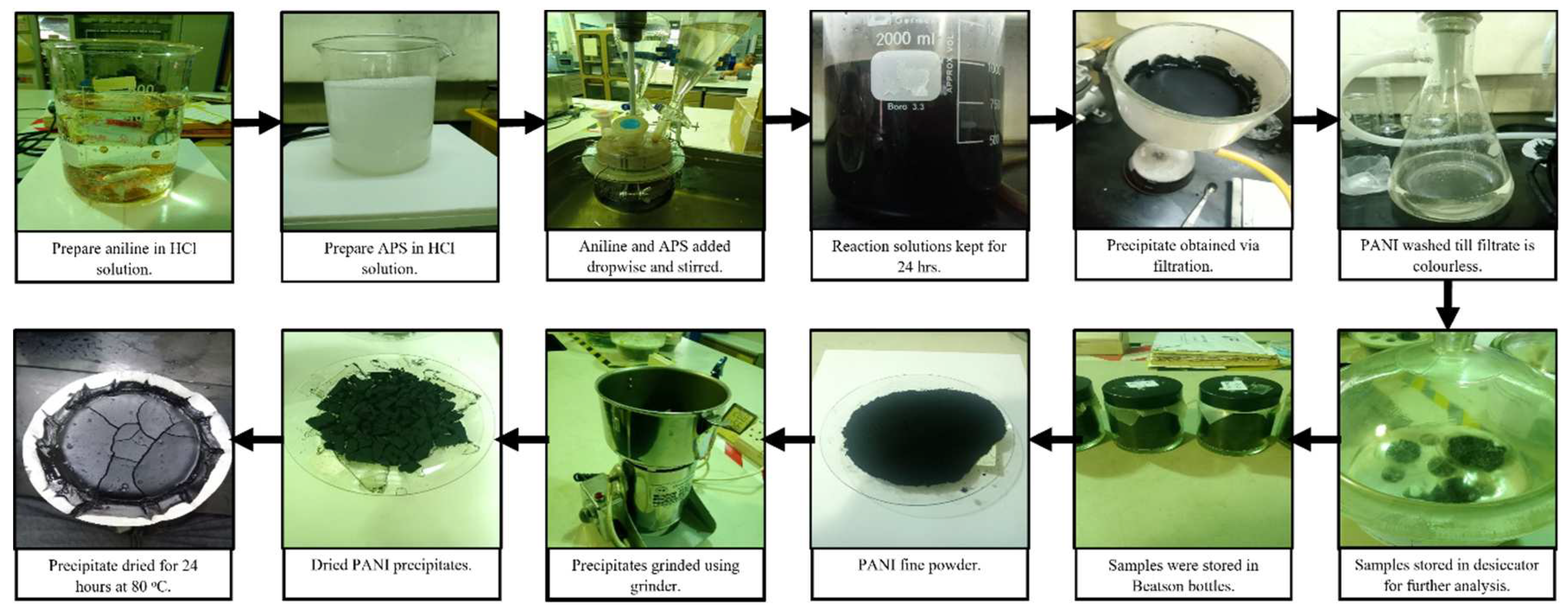
Figure 2.
FTIR of PANI synthesized with different r..
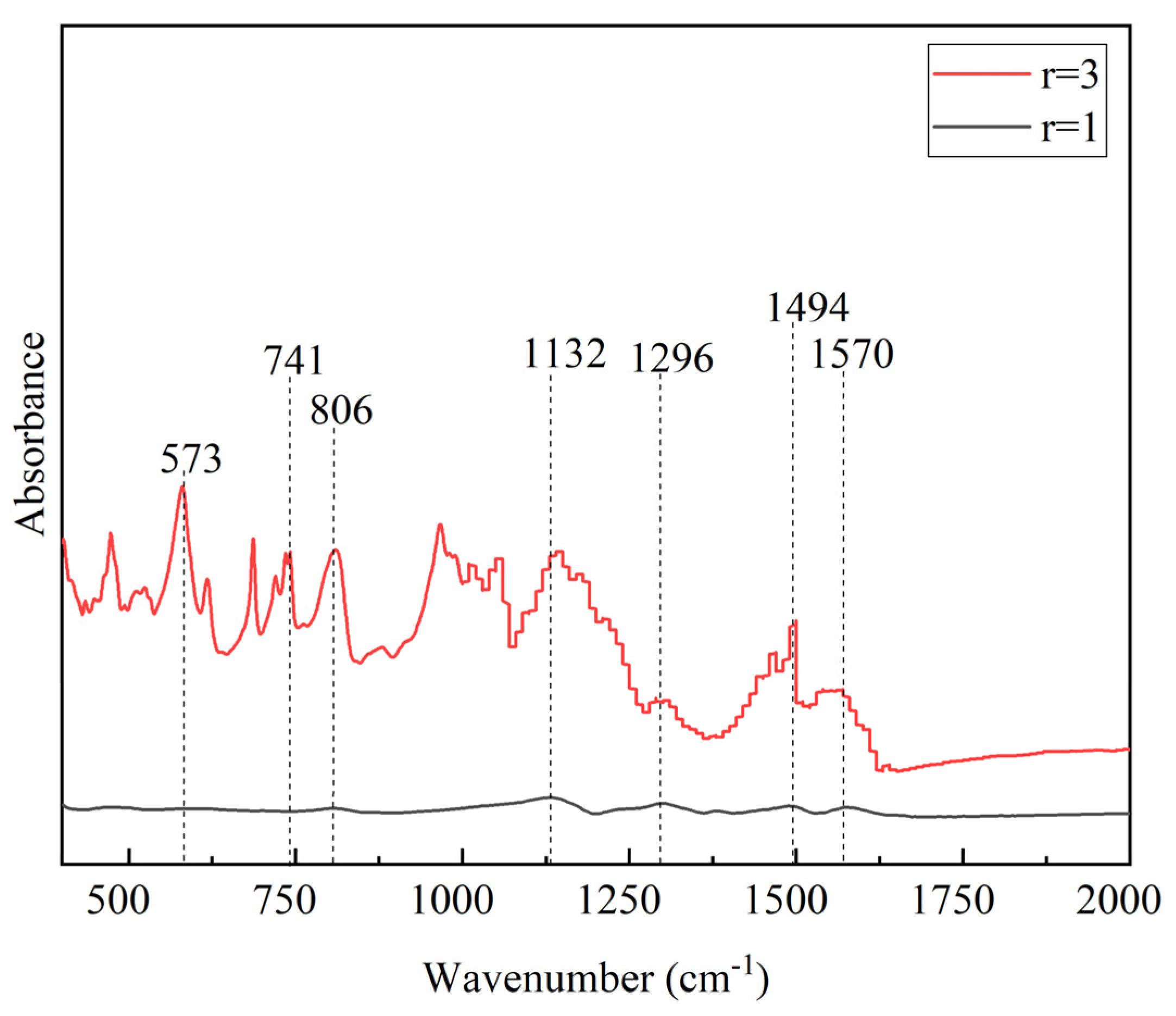
Figure 3.
FTIR of PANI synthesized with different stirring speed.
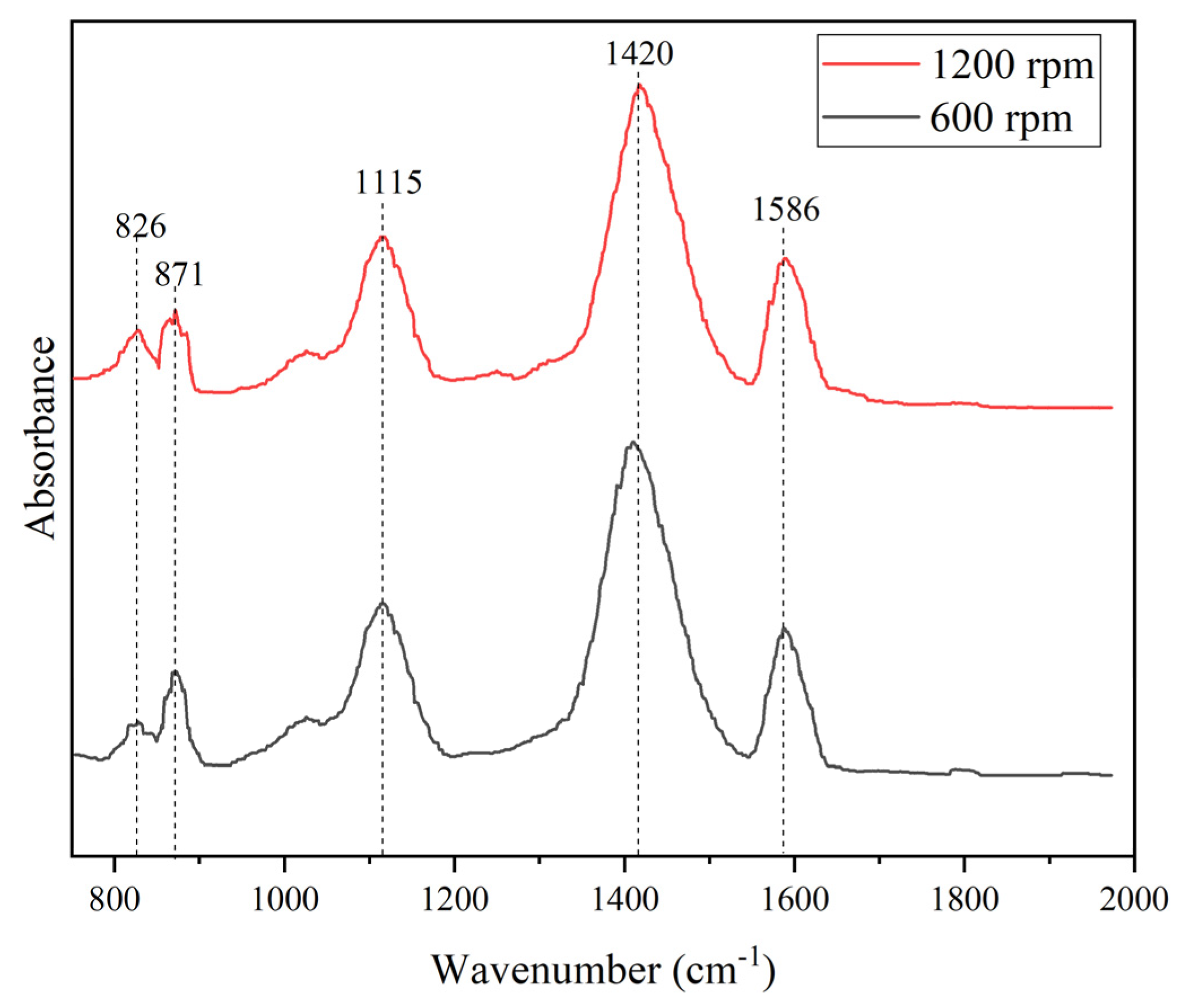
Figure 4.
Particle size distribution of PANI synthesized at a) 600 rpm and b) 1200 rpm.
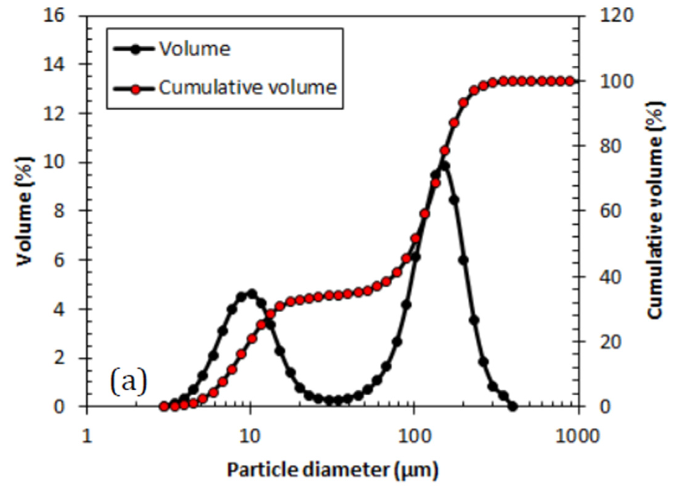
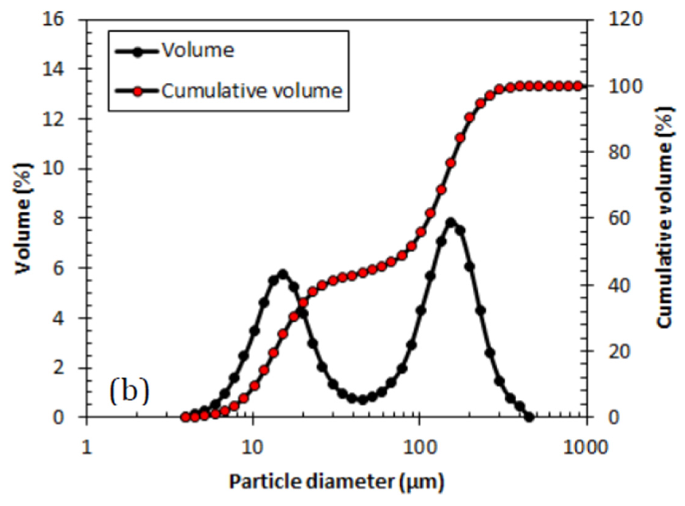
Figure 5.
Particle size of PANI synthesized in different temperature.
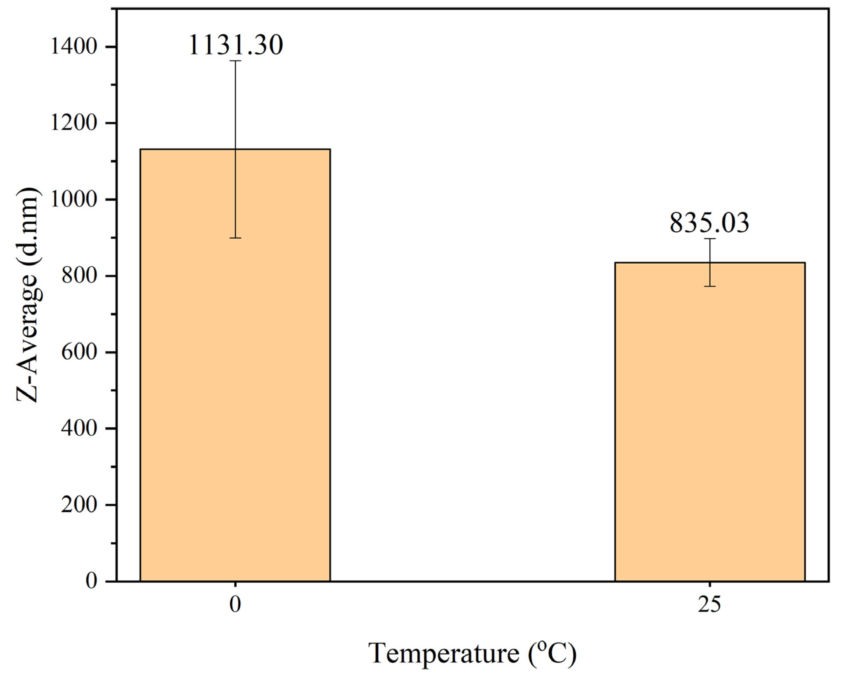
Figure 6.
FTIR of PANI purified by heating or filtration.
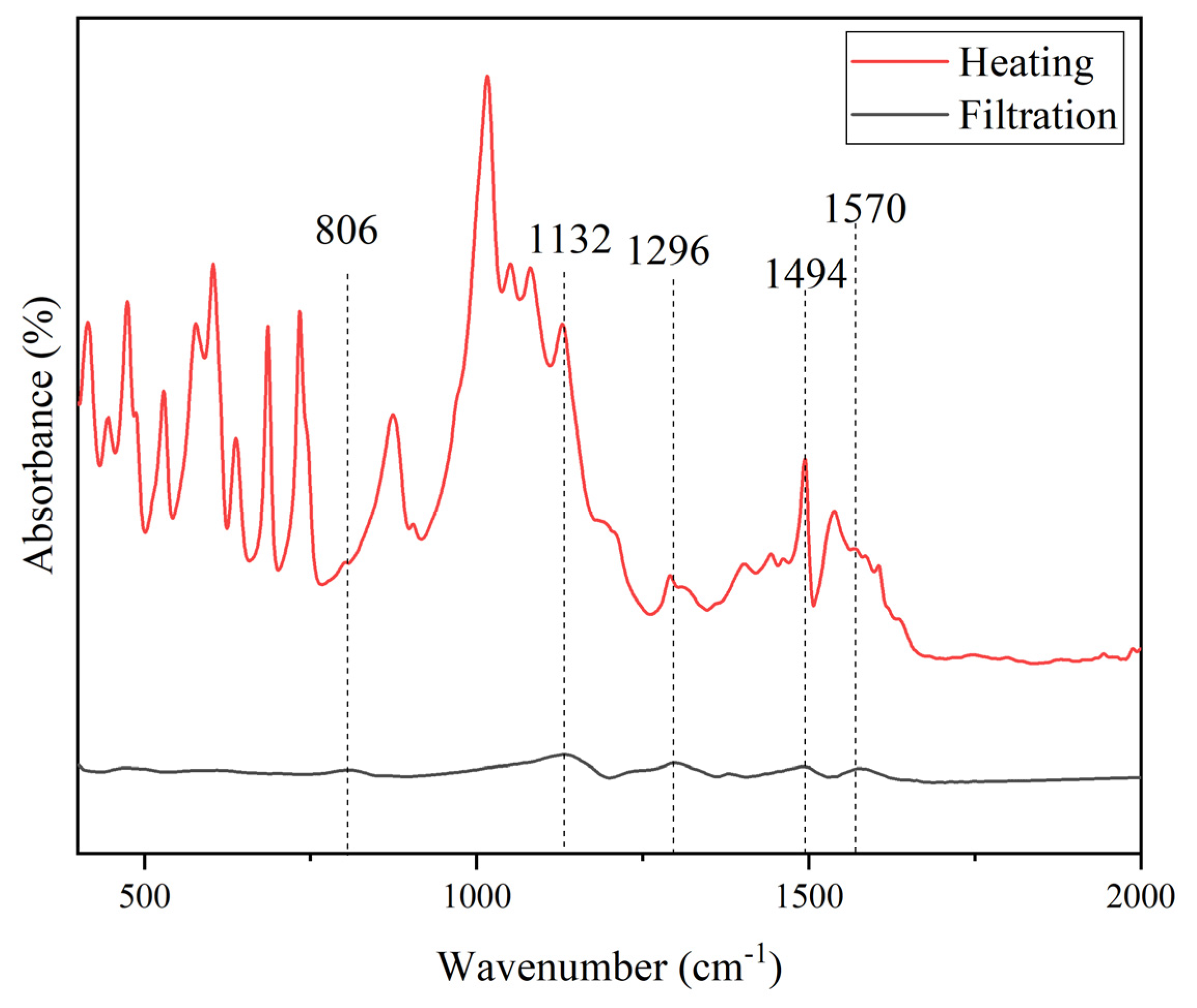
Figure 7.
Particle size analysis of PANI with different purification method.
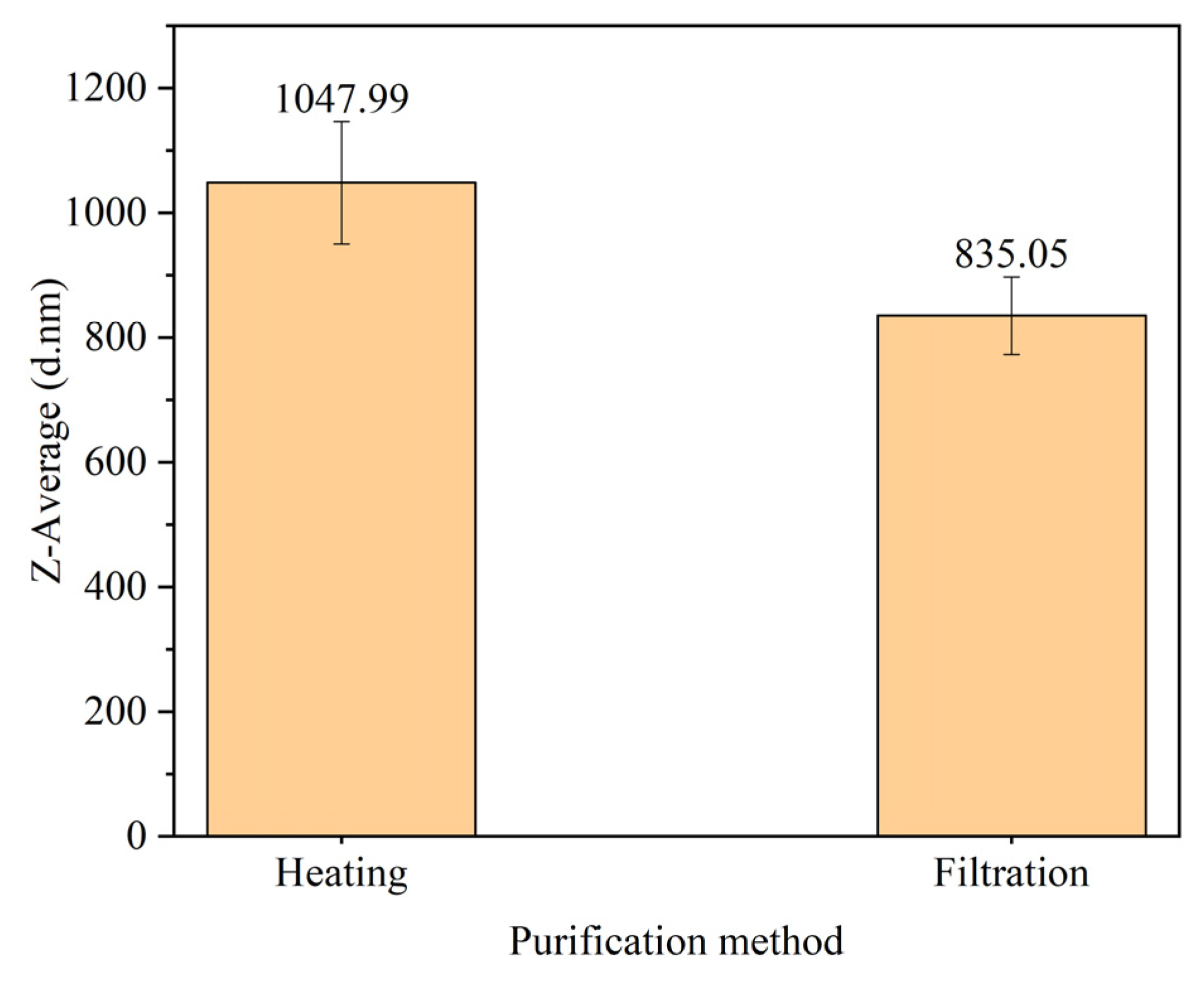
Figure 8.
FTIR of PANI filtrate.
Figure 9.
Particle size analysis of PANI washed with different substances.
Figure 10.
FTIR of PANI-SDS.
Figure 11.
FTIR of PANI-TX100.
Figure 12.
Particle size analysis of PANI synthesized with SDS and TX100.
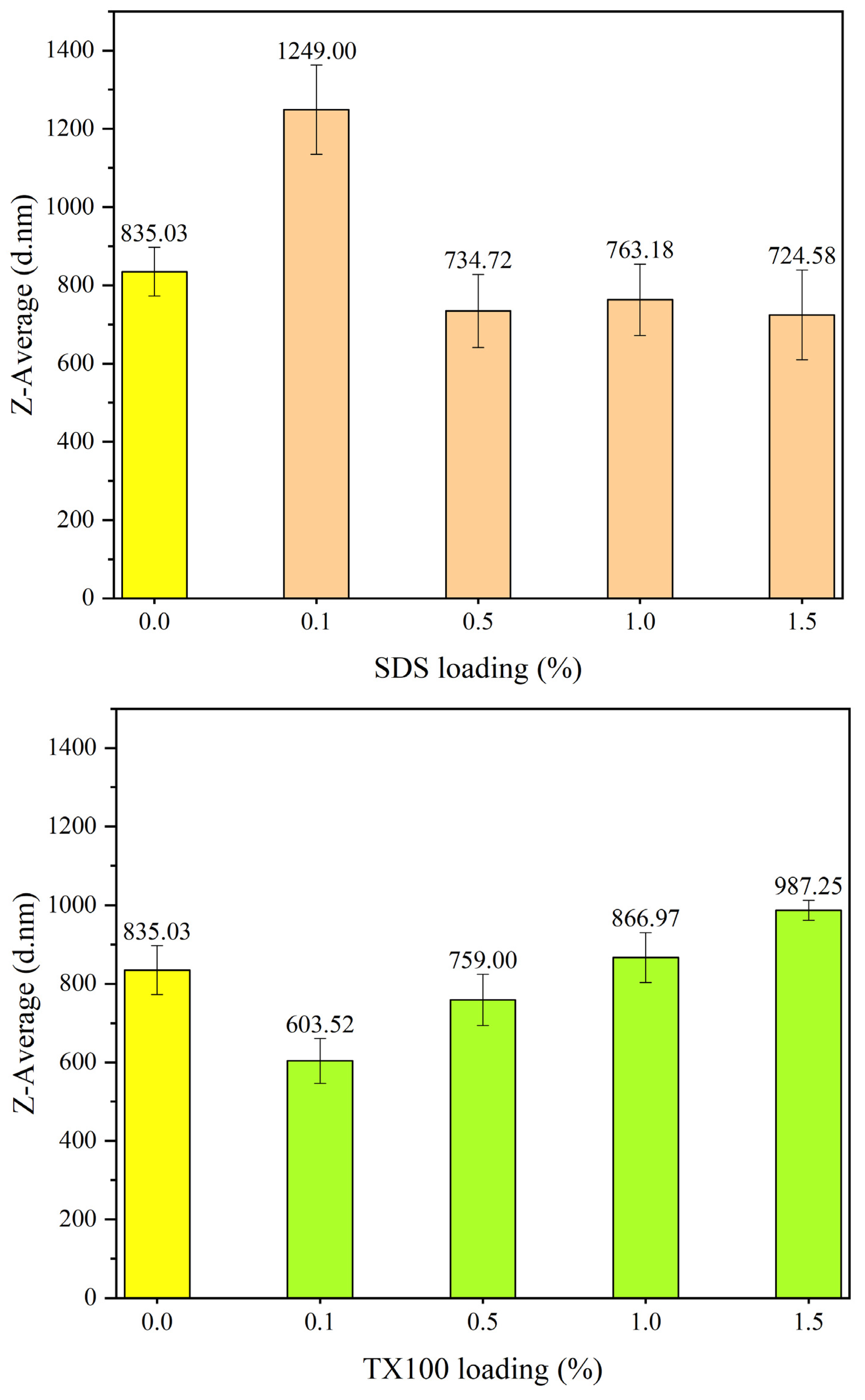
Figure 13.
Dispersion of a) PANI-SDS and b) PANI-TX100 in distilled water at pH 7: At Day 1(above) and Day 7(below).
Figure 13.
Dispersion of a) PANI-SDS and b) PANI-TX100 in distilled water at pH 7: At Day 1(above) and Day 7(below).
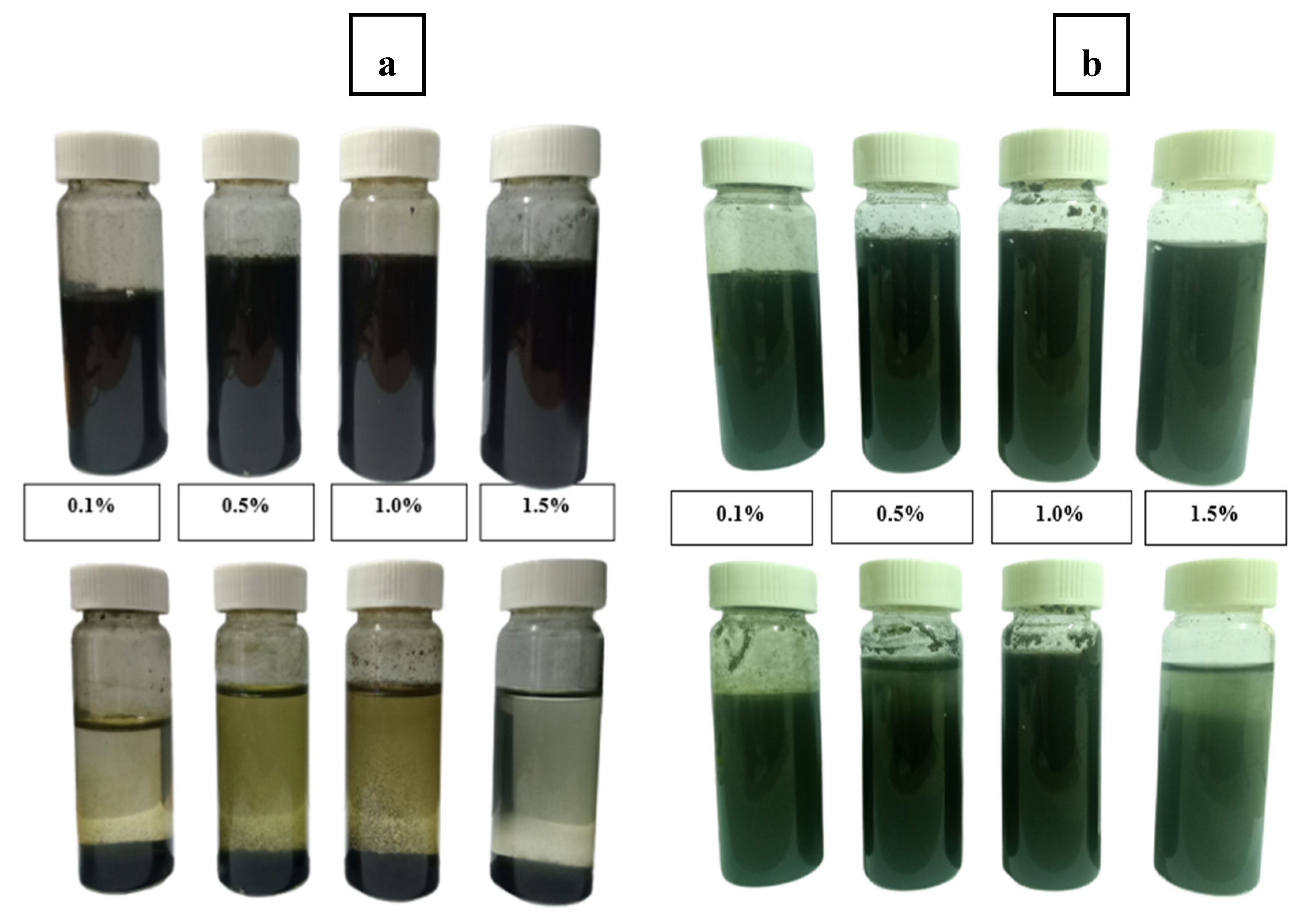
Table 1.
List of chemicals.
| Chemicals | Usage | CAS No | Brand | Chemicals | Usage |
|---|---|---|---|---|---|
| Aniline, > 99.5% | Monomer | 62-53-3 | Sigma-Aldrich | Aniline, > 99.5% | Monomer |
| Ammonium persulphate | Oxidizing agent | 7787-54-0 | R&M Chemicals | Ammonium persulphate | Oxidizing agent |
| Hydrochloric acid, Fuming 37% | Doping agent | 7647-01-0 | R&M Chemicals | Hydrochloric acid, Fuming 37% | Doping agent |
| Sodium dodecyl sulphate | Anionic surfactant | 151-21-3 | Bendosen | Sodium dodecyl sulphate | Anionic surfactant |
| Triton X-100 | Non-ionic surfactant | 9036-19-5 | Sigma-Aldrich | Triton X-100 | Non-ionic surfactant |
| Acetone, >99.5% | Washing agent | 67-64-1 | Sigma-Aldrich | Acetone, >99.5% | Washing agent |
Table 2.
Precursor method.
| Chemicals | Chemicals |
|---|---|
| Initial molar ratio of Aniline: APS (r) | 1 (0.2 M: 0.2 M) |
| Stirring speed during period of synthesis | 800 rpm |
| Synthesis temperature | 0 – 2 oC |
| Purification method | Filtration |
| Chemicals used for washing. | Washing agent with the order: 0.2 M HCl 0.2 M acetone Distilled water |
| Surfactant usage | Not applied |
Table 3.
Parameters for particle size analysis of PANI.
| Material | PANI |
|---|---|
| Refractive Index | 1.021 |
| Absorption Index | 0.318 |
| Dispersant | Distilled Water |
| Dispersant Refractive Index | 1.330 |
Table 4.
Yield of PANI synthesize with different r.
| Sample | Initial molar ratio, r | Molar concentration (M) | Weight of aniline (g) | Weight of PANI (g) | % Yield | |
|---|---|---|---|---|---|---|
| Aniline | APS | |||||
| Equal molar | 1 | 0.2 | 0.2 | 5.10 | 4.61 | 90.39 |
| Nonequal molar | 3 | 0.3 | 0.1 | 6.12 | 2.12 | 34.72 |
Table 5.
Yield of PANI synthesize with different r..
| Sample | Population | Range (µm) | Median Diameter (µm) |
|---|---|---|---|
| PANI 600 rpm | 1 | 2.41-29.91 | 10.10 |
| 2 | 29.91-344.21 | 152.45 | |
| PANI 1200 rpm | 1 | 4.47-44.94 | 15.17 |
| 2 | 44.94-394.24 | 152.45 |
Disclaimer/Publisher’s Note: The statements, opinions and data contained in all publications are solely those of the individual author(s) and contributor(s) and not of MDPI and/or the editor(s). MDPI and/or the editor(s) disclaim responsibility for any injury to people or property resulting from any ideas, methods, instructions or products referred to in the content. |
© 2023 by the authors. Licensee MDPI, Basel, Switzerland. This article is an open access article distributed under the terms and conditions of the Creative Commons Attribution (CC BY) license (http://creativecommons.org/licenses/by/4.0/).
Copyright: This open access article is published under a Creative Commons CC BY 4.0 license, which permit the free download, distribution, and reuse, provided that the author and preprint are cited in any reuse.


