
Submitted:
27 June 2023
Posted:
28 June 2023
You are already at the latest version
Abstract
High-efficiency rock breaking by hydraulic jetting is the key to radial horizontal drilling technology. In order to improve the drilling efficiency of hydraulic jet rock breaking in radial horizontal wells, based on LS-Dyna display dynamics, a numerical simulation model of single nozzle jet rock breaking is established to analyze the influence of different nozzle parameters on rock breaking effect. Then, the numerical simulation model of the spin multi-nozzle jet bit is established, and the influence of different rotation speeds on the rock breaking effect of the jet bit is analyzed. Finally, the rock breaking drilling characteristics of the spin multi-nozzle jet bit and the conventional multi-nozzle jet bit are compared and analyzed. The results show that when the jet impacts the rock surface, the larger the inclination angle is, the larger the rock breaking width formed by the jet is. The smaller the dip angle, the greater the rock breaking depth. When the inclination angle is greater than 60 °, it is difficult to meet the needs of reaming. The width and depth of the nozzle gradually increase with the increase of the diameter. When the nozzle diameter is greater than 1.3mm, the growth rate of rock breaking depth begins to decrease. The optimum nozzle diameter is 1.3 mm. When v = 50m / s, the damage caused by the jet to the rock surface is very small, because the condition of rock fracture is not reached at this time. This shows that there is a critical value of the water jet impact velocity, and only when the velocity is reached, the rock will break. When the velocity is v = 150m / s, v = 200m / s, v = 250m / s, v = 300m / s, the rock breaks. At the same time, the higher the speed, the higher the degree of rock fracture, the greater the fracture depth, the greater the fracture area, the better the fracture effect. The tangential and radial velocity of the jet increases the shear and tensile failure rate of the sample, and improves the rock breaking efficiency of the jet, which has certain guiding significance for improving the rock breaking drilling efficiency of radial horizontal well drilling.
Keywords:
Display dynamics
; hydraulic jetting
; spinning multi-nozzle jet bit
; high efficient rock breaking
; dynamic rock-breaking drilling
1. Introduction
With continuously economic and social development, human demand for oil and gas resources has further increased, resulting in insufficient reserves and increasing difficulty of exploitation. Traditional mining methods are no longer suitable for the current technical needs, so more and more new technologies have emerged. With its unique advantages of environmental protection and efficiency, high-pressure water jet is widely used in quarry rock breaking, coal seam drilling, oil drilling, geothermal mining and deep-sea shallow drilling [1,2]. This technology can not only avoid or greatly reduce formation damage caused by conventional perforation technique, but also penetrate the contaminated areas in the near-well zone for improved oil drainage and production in the oil layer, thereby increasing crude oil production [3,4,5].
The high-pressure water jet rock-breaking process is affected by many factors such as the form of the drill bit and the jet flow field of the nozzle, which makes the process extremely complicated. With continuously advanced technology and equipment, spin jet bits have become a cutting-edge research hotspot for many scholars. The spin bit relies on the reverse thrust generated by the jet flow of eccentric nozzle to spin, and its breaking effect on coal and rock is affected by the velocity of rotation, pump pressure, bit spacing, and nozzle space arrangement. Therefore, it is of great significance to study the relationship between the rock-breaking effect of spin drill bit and the influence parameters.
The spin jet bit is composed of multiple jet nozzles whose combined rock-breaking effect is an important prerequisite for its application in drilling engineering. And the nozzle structure is one of the main factors affecting the efficiency of rock breaking [6]. Different nozzle inclination has different water jet patterns, leading to different rock-breaking patterns [7]. In earlier studies, researchers built a simple multi-nozzle drilling model that theoretically verified the rationality of rock-breaking mechanism of multi-nozzle water jet [8]. It has been found that, in further studies of multi-nozzle water jet drilling, a reasonable nozzle arrangement can improve drilling efficiency [9,10,11]. The hole drilling process of the multi-nozzle bit is mainly affected by the interaction of the multi-nozzle jet flow, of which the energy conversion efficiency is crucial. As for the design of multi-nozzle bit, it is necessary to increase the diameter of the nozzle on the basis of ensuring the ability of rock breaking for holes so as to improve the hydraulic performance of each single nozzle as much as possible. At present, the study of the multi-nozzle structure parameters focuses on the effect of the nozzle structure on the jet flow and the comparison of the rock-breaking efficiency of different bit structures. With CFD software, the influence of nozzle with different inclination on the jet flow can be analyzed to obtain distribution of axial velocity and radial velocity [12,13]. However, the jet rock-breaking state and fragmental pit formed by water jet flow from different angles are still difficult to quantify.
Experiment is a direct and reliable method to study water jet technology, but it is very difficult to observe the the jet flow distribution and the physical rock-breaking process on which the research would also be limited due to experimental cost and conditions. With the development of computing technology, the state analysis at any time in the process of rock breaking can be carried out by numerical simulation method. Wang Hongxiang [14] simulated and analyzed the effect on rock damage by impact velocity, incident angle, and movement velocity of jet flow. Liu Jialiang compared the evolution of fragmental pits under the action of high-pressure water jet in the state of no confining pressure and high confining pressure. He believed that the axial evolution rate of rock damage in high confining pressure state is significantly lower than that in the unconfining pressure state, and that the radial damage evolution is less affected by confining pressure. [15] Sun Qingde [16] used the nonlinear finite element method to study the rock-breaking law of high-pressure water jet, and proposed that the process of jet flow breaking rock is divided into jet flow erosion wear and hammering wear. The above results have further deepened the research on the mechanism and characteristics of rock breaking by jet flow with some research progress. However, they usually simplified the real continuous jet flow as a water column which are different. Therefore, this paper took the spin bit with multi-nozzle jet flow as the research object, used the SPH-FEM coupling algorithm to achieve jet continuity, established a single-jet rock-breaking model for dynamical simulation of the rock-breaking process, and analyzed the impact of different parameters on the rock-breaking effect. Based on this, a rock-breaking model of spin bit with multi-nozzle jet flow is established, which is compared with conventional bit. The different drilling characteristics of the rock breaking were analyzed as well as the rock-breaking effect of the spin bit with multi-nozzle jet flow at different velocity. The research results can improve the understanding of the high-pressure water jet rock-breaking process and provide guidance on the design of such spin bit.
2. Basic Principles of SPH-FEM Coupling Algorithm
The Smoothed Particle Hydrodynamics (SPH) -FEM coupling algorithm is a gridless Lagrange algorithm that discretizes moving points (particles or nodes) with fixed mass and was proposed by Lucy [17] and Gingold [18] in 1977. As the mass of each particle in the coordinate system is fixed, the large deformation problem can be solved without producing grid deformation. It was originally used to solve astrophysical problems in three-dimensional open space, where smooth particles move according to laws similar to fluid motion. The SPH method is based on interpolation theory. The particle interpolation function (kernel function W) works over short distance to describe the relationship between spatial particles and their neighbors [19], while macro variables are obtained through integral interpolation. The problem domain can be described by a set of discrete points [20], and for any homogeneous continuous field function f (x), it can be expressed as follows:
The SPH-FEM coupling algorithm compensates for the shortcomings of finite element modelling and Euler grid deformation, large computation, time and memory resource consumption. The basic principle of SPH-FEM coupling is thought to be the contact issue between the smooth particles and the finite element interface, which is achieved by a constraint [21] function, such as the normal spring K, placed between the smooth particles and the finite element interface creating a node that limits surface penetration. In this way, the role of the jet flow (SPH particles) is transferred to the rock mass (finite element body), so this is the method of erosion-node-surface point contact by the SPH-FEM coupling. And erosion occurs when the energy absorbed by the finite element body reaches its fracture strength.
3. Study on the Rock-breaking Drilling Characteristics of a single nozzle on the Spin Bit with Multi-nozzle Jet Flow
Assuming that the jet flow strikes the rock at an appropriate speed from the multi-nozzle bit, the flow can be simplified as a regular cylindrical shape spurted from the nozzle outlet at different incident angles. The structural parameters was optimized by earlier numerical simulation of a single nozzle performance before the rock-breaking simulation of spin bit with multi-nozzle jet flow.
3.1. Structure and Principle of Spin Bit with Multi-nozzle Jet Flow
The spin bit with multi-nozzle jet flow, whose structural diagram and stereoscopic diagram are shown in Figure 1 and Figure 2, is designed on the basis of the bit with multi-nozzle jet flow. It is mainly composed of parts such as rotary body, inner baffle plate, friction-reducing ball, center body, adjusting gasket and outer baffle plate. To reduce the frictional resistance of the nozzle rotary body during rotating, a friction-reducing ball is inserted between the rotary body and the revolving outer baffle plate, changing the sliding friction into rolling friction for thereby decreased frictional resistance. And a gasket is set to adjust the axial clearance between the center body and the rotary body. Simplify the bit as a whole into two parts: a rotary body and a non-rotary body, and set up a number of spatially inclined nozzles on the rotary body. By adjusting the opening angle of the front nozzle, the jet of the spacial nozzle can generate tangential reverse thrust for rotational torque which enables the rotating body to rotate around its axis, thereby achieving large-area jet cutting by the nozzle and enhancing the hole-expanding ability of the jet bit. The rear end of the rotating body is equipped with a reverse nozzle which has a certain eccentricity angle with the central axis. The reverse thrust generated by the reverse nozzle is greater than that generated by the forward nozzle, generating self-propulsion of the bit in the drilling direction for its rotation and self-motion while breaking rock.
Assuming that the jet flow strikes the rock at an appropriate speed from the multi-nozzle bit, the flow can be simplified as a regular cylindrical shape spurted from the nozzle outlet at different incident angles. The structural parameters was optimized by earlier numerical simulation of a single nozzle performance before the rock-breaking simulation of spin bit with multi-nozzle jet flow.
3.2. Geometric Models
The effect of the nozzle parameter on rock-breaking effect is mainly reflected in the inclination and the nozzle diameter. High-pressure water jet have an impact force on the rock mass after impinging the rock at an certain angle, which includes a vertical direction and a parallel direction on the rock surface. And the two impact forces can be characterized by the depth and width of the hole. Therefore, LS-Dyna was used to simulate the rock-breaking process of jets from different angles. Its physical model is shown in Figure 3.
3.3. Grid Division
The main method of grid division is the free grid and the mapping grid. The free grid method does not limit the shape of the cells without definite pattern in the grid division, resulting in a large number of grid cells becoming very irregular grid shapes. In contrast, the mapping grid method has fewer grid cells and more regular grids than the former with more rigid structure.
The model established in this paper is mainly a cube with relatively regular structural space, so this paper adopted the mapping grid method. To ensure high accuracy and save the amount of calculation, the grid is densified in the area close to the contact surface of the water jet with the rock, while the density of the grid can be reduced accordingly in the area deviated from the contact surface. Figure 4 and Figure 5 show partial grid diagrams of rock and water jets
3.4. Boundary Conditions
Jet boundary conditions: On the YOZ interface, displacement in the X direction is restricted; on the XOZ interface, displacement in the Y direction is restricted.
Boundary condition of rock mass: It limits the amount of displacement between the rock mass and the YOZ plane in the X, Y, and Z directions, and the amount of displacement between the X and YOZ plane; Unreflected boundary is also applied to both sides and the base of the rock mass to simulate an infinitely large area.
3.5. Material Model and Parameters
The high-pressure water jet was regarded as a fully plastic material, and the material model is used to define the LS-Dyna water material whose [15] internal structure is defined by the state equation of Grueisen which simultaneously determines the tensile and compressive strength of the material and is particularly suitable for evaluating the material deformation under high pressure.
In LS-Dyna, the specific form of the state equation of Grueisen is as follows:
When the material is under pressure, it can be expressed as:
In the equation:—— impulse pressure
- —— first order volume correction;
- —— the Grueisen constant;
- —— the truncation distance (shock wave velocity - mass point velocity curve;
- —— internal energy per unit volume;
- —— liquid viscosity coefficient;
- , and —— the slope of the shock wave and the velocity change curve of the mass point.
When the rock is impacted by high-pressure water, it exhibits high stress, large deformation, non-linearity and other characteristics. In order to better characterize the failure behavior of rock mass, the Johnson-Holmquist-Concrete (H-J-C) internal model was used when calculating rocks with high strain rate and large deformations [22]. H-J-C is developed based on standard concrete that conforms to the mechanical properties of rock masses, corresponding to the mechanical properties of rocks. This model contains several characteristics, such as a plastic yield surface with a smooth contraction surface, three stress-releasing yield surfaces with preheating translation, softening and erosion based on damage and modulus reduction, and strength-increasing effect in application of high deformation rate. Therefore, the H-J-C model is suitable for modeling rocks with large deformation, high strain rate and high pressure.
Under the influence of the jet, the rock will break and be eroded. When LS-Dyna is used, the material is usually decomposed and its clearance is enlarged by a scavenging device. To determine the criteria to remove rock properly broken and eroded, the erosion keyword “Mat-Add-Erosion” must be added to the finite element model of rock mass, and a Mat-id material identical to the rock material must be specified. Criteria for crushing include maximum crushing stress, minimum crushing principal stress and maximum crushing principal stress. When the accumulated stress of the rock reaches its maximum destructiveness, the rock will be broken apart and be removed.
The parameters of the water jet material [23] and the state equation of Grueisen in this paper are shown in Table 1 and Table 2.
And the parameters of the rock constitutive model are shown in Table 3.
3.6. Influence of Different Nozzle Parameters on Rock Breaking Effect
- (1)
- Influence of nozzle inclination on rock breaking effect
Figure 6 and Figure 7 are the stress damage diagram and fragmental pit shape diagram of different angle jets impacting rocks, respectively. The results showed that the breaking width increases along with the increasing jet inclination, and the breaking depth decreases along with the increasing jet inclination. Under the comparison of the crushing shape, it was found no obvious shape change at 0° and 10 °until the increased inclination angle from 20° to 50°, and the largest change at 60°. The main reason is that the jet impact force from a certain bevel angle can be decomposed into axial impact and radial impact. As the angle increases, the impact force of the radial line gradually increases, while the impact force of the axial line gradually decreases. Because the compressive strength of the rock is much higher than its tensile strength, the damage of the rock is mainly depended on tensile failure. Therefore, it can be obtained that when the jet strikes the surface of the rock, the greater the inclination angle is, the greater the width of the rock breaking by the jet is; and the smaller the inclination angle is, the greater the depth is.
Figure 8 shows the variation of the depth and radial width of the rock breaking along with the angle of jet inclination at the same time. The above figure shows that the width increases as a power function with the increasing inclination angle, and that the change trend is basically the same. The depth gradually decreases along with the increasing inclination angle, while the width increases instead. In term of the design of the multi-nozzle bit for rock-breaking, it is necessary to meet the larger borehole diameter, so it is essential to select a reasonable inclination angle to expand the drilling. From the breaking shape of Figure 5, it is difficult to meet the expansion needs if the inclination angle is greater than 60°. According to the changing trend of the curve and the amount of the breaking, the nozzle at 30° is optimal.
- (2)
- Influence of nozzle diameter on rock breaking effect
Figure 9 shows the stress damage diagram of jet flow impacting rocks with different nozzle diameters. It can be obtained from the diagram that the fracture volume of rock mass increases linearly with the increasing diameter of the water jets. In terms of the depth and width of the pit, when the jet diameter is in a small scope, the depth of the fragmental pit is greatly affected by the jet diameter, gradually increasing along with the increasing jet diameter. However, when the diameter increases to a certain extent, the depth will decrease instead. And the increase amount of the breaking is mainly caused by the expansion of the cross-sectional area of the pit.
Figure 10, Figure 11, Figure 12 and Figure 13 are comparative diagrams of breaking shapes formed at time points of 100 μs and 250 μs under diameters of 0.7 mm, 1 mm, 1.3 mm and 1.6 mm, respectively. It can be seen from the figure that with the increasing jet diameter and erosion time, the erosion holes increases rapidly because of increasing erosion force as the jet flow and kinetic energy increase along with the increasing diameter.
In Figure 14, by comparing the effect of the nozzle diameter on the depth and width of rock breaking, it can be seen that the width and depth gradually increase as the diameter increases. However, when the nozzle diameter is greater than 1.3 mm, the growth rate of depth begins to decline. That is to say, a relatively small nozzle diameter dominates the breaking depth by water jet flow while a relatively large diameter dominates the width. Therefore, the best nozzle diameter is 1.3mm.
- (3)
- Influence of Water Jet Velocity on Rock Breaking
Figure 15 and Figure 16 are the stress damage diagram of water jet impacting rock at different velocities and the variation of breaking depth along with jet velocity change, respectively. It can be seen from the figure that the velocity of v = 50m/s has little damage to the rock surface, which is not a condition for rock fracture. This shows that there is a threshold value for the impact velocity of the water jet, and only when this velocity is reached will the rock crack. At the velocity of v = 150m/s, v = 200m/s, v = 250m/s, v = 300m/s, the rock ruptures. And the higher the jet velocity is, the higher the degree of rock fracture is, with deeper depth and larger area achieving better breaking effect.
4. Study on the Rock-breaking Drilling Characteristics of the Spin Bit with Multi-nozzle Jet Flow
On the basis of completing the numerical simulation study of a single nozzle breaking rock, we established a model of spin multi-nozzle bit breaking rock to analyze the process.
4.1. Geometric Models
A model of the rock fragmentation process is shown in Figure 17; It includes two parts: the bit and the rock.
The bit is composed of a bit and a positive nozzle jet column. The bit can be simplified as a cylinder with an end diameter of 30 mm, which is the maximum outer diameter of the nozzle. The jet diameter is 1.3 mm. The jet column is composed of five small cylinders, connected to the nozzle. The central nozzle is on the nozzle axis, and the central forward nozzle has a deflection angle of 30°. The external nozzle has a deflection angle of 30° and an opening angle of 20°.
The rock is supposed to be unlimited rock space, but it is designed into a 40cm × 40cm × 10cm cuboid to simplify the calculation.
To improve the accuracy of the calculation, the grid is subdivided according to the mapping grid method, which should be modeled according to the requirements of the previous section. The incoming erosion contact algorithm should be used between the water jet and the rock, and the failed cell can be removed in time during the breaking process.
The keyword * CONTACT_ERODING_SURFACE_TO_SURFACE is used. Taking into account that the water column smashes the rock in a very short time, the analysis time is 800 μs.
4.2. Influence of Spin Multi-nozzle Bit on the Rock-breaking Effect at Different Velocity
Figure 18 is a comparison of the rock-breaking effect of spin multi-nozzle bit at different velocity.
It can be seen from Figure 18 that the effective breaking area continues to widen along with the increasing jet rotation velocity, and there is no overall fragmental pit at the velocity of 20rps. The pit continues to be larger at the increased velocity of 40rps, with an widened area of pit twice as much as before at the same time. And a complete fragmental pit forms at the increased velocity of 60rps. This shows that rotating jet can significantly improve the breaking effect, effectively reducing the specific energy of jet breaking. There are two main reasons for this: First, the effective area by the jet is different with main difference of the impact area. Compared with the single-point fracture height generated by fixed jet scouring, the circular impact generated by rotating jet has a larger influence range and a more uniform distribution, which plays a certain role in the stability of the jet. Secondly, the rock-breaking effect also varies. In the rotating state, the impact point of the jet on the specimen is always in the flow position, which can effectively inhibit the"water cushion effect"caused by the backflow at the bottom of the pitshaft, and can also enhance the rock-breaking effect while reducing the energy conversion at the pitshaft. In addition, the tangential and radial velocity of the jet under rotational condition increases the rate of shear and tensile destruction to the sample, improving the rock-breaking efficiency. In general, the rock-breaking efficiency can be effectively improved if the jet breaks the rock at a certain rotational velocity.
4.3. Comparative Analysis of Drilling Characteristics of Bits
Figure 19 and Figure 20 are the drilling characteristics of spin multi-nozzle bitand conventional multi-nozzle bit, from which we can see that the spin bit drills forward in a circular manner, featuring clear outer contour, larger aperture and conical pitshaft; while the outer edge of the other bit is quincunx with positive jet flow and water wedge around, featuring clear outer edge, uneven aperture and deeper fragemental pitshaft. Over time, the spin jet rotates around the center axis of the bit forming a circular fracture surface; and the jet formed by longer rotation semidiatmeter of the jet hole can not break enough rock on the outer ring line due to the short breakage time of the rock per unit area and the conical fragmental pit caused by the interference between the jets. In multi-nozzle jet drilling, the energy concentration of the jet is fixed, so there is little depth change to the bottom of the fragmental pit.
4.4. Mechanism of Rock-breaking and Drilling of Spin Bit with Multi-nozzle Jet Flow
Based on the analysis of numerical simulation of a single nozzle breaking rock and study on drilling characteristics of spin multi-nozzle bit breaking rock, we can get its mechanism of drilling through fracture and damage to coal rock. As shown in Figure 21, an intermittent jet from the front end of the bit crushes the coal rock. Because the impact point of the jet is not fixed, the "water cushion effect" is effectively weakened, resulting in fatigue rupture to coal. At the microscopic level, the intermittent water jet first clears the low-intensity cement and rock particles, and then leads to the matrix brittle fracture through its tensile force; At the macroscopic level, the rotational action of the water jet breaks the rock, forming a V-ring hole to destroy the surrounding rock; And the quasi-static water pressure further breaks the coal rock, forming a macroscopic fracture point. The ring-shaped fracture zone of the central jet and the lateral jets with different propagation radius overlap to form a circular, connected borehole. On the other hand, the backward jet provides thrust to the bit, allowing the bit to move forward automatically and further grind the coal to increase the aperture and then discharge the grinded coal into the hole. In this way, continuous high-speed drilling can be ensured.
5. Conclusions
Using the SPH-FEM method, a coupling model of high-pressure jet breaking rock was established to simulate the water jet rock-breaking process. First, a model of a single-nozzle water jet breaking rock was established to analyze the influence regularity of jet structure parameters. And then the dynamic analysis software LS-Dyna numerical value was used to simulate the situation of the spin multi-nozzle bit breaking rocks. The results showed that:
(1) During the simulation of a single-nozzle jet breaking rock, it has been found that when the jet strikes the surface of the rock, the greater the inclination angle is, the greater the width of the broken rock by the jet is; and the smaller the inclination angle is, the greater the depth is. It is difficult to meet the expansion needs if the inclination angle is greater than 60 °. According to the changing trend of the curve and the amount of the breaking, the nozzle at 30 ° is optimal. The width and depth of the nozzle gradually increase with its increasing diameter. However, when the nozzle diameter is greater than 1.3 mm, the growth rate of rock-breaking depth begins to decline. Therefore, the best nozzle diameter is 1.3mm.
(2) The velocity of v = 50m/s has little damage to the rock surface, which is not a condition for rock fracture. This shows that there is a threshold value for the impact velocity of the water jet, and only when this velocity has reached will the rock crack. At the velocity of v = 150m/s, v = 200m/s, v = 250m/s, v = 300m/s, the rock ruptures. Meanwhile, the higher the jet velocity is, the higher the degree of rock fracture is, with deeper depth and larger area achieving better breaking effect.
(3) In addition, the tangential and radial velocity of the jet under rotational condition increases the rate of shear and tensile destruction to the rock, improving the rock-breaking efficiency. Generally speaking, the rock-breaking efficiency can be effectively improved if the jet breaks the rock at a certain rotational velocity.
(4) The mechanism of spin bit with multi-nozzle jet flow has been revealed, that is, the periodical movement of the spin jet generated by the front nozzle of the bit makes the rock to be broken, weakening the "water cushion effect" and eventually leading to the huge rupture; The rupture range is achieved by forming a circular connected hole. On the other hand, the jet from backward nozzle provides thrust to the bit, allowing the bit to move forward automatically and further grind the coal to increase the aperture and then discharge the ground coal into the hole. In this way, continuous high-speed drilling can be ensured.
Author Contributions
Methodology, G.B. and X.W.; conceptualization, G.B. and F.H.; investigation, G.B. and J.W.; data curation, P.Y. and Y.M; writing—original draft, X.W.; writing—review and editing,G.B. and S.F.;. All authors have read and agreed to the published versionof the manuscript.
Funding
This work was is supported by Foundation of State Key Laboratory of Petroleum Resourcesand Prospecting, China University of Petroleum (Grant No. PRP/open-2113) and National Natural Science Foundation (Number52104033).
Data Availability Statement
The data presented in this study are available on request from the Authors.
Acknowledgments
The project is supported by Foundation of State Key Laboratory of Petroleum Resourcesand Prospecting, China University of Petroleum (Grant No. PRP/open-2113) and National Natural Science Foundation (Number52104033).
Conflicts of Interest
The authors declare that they have no known competing financial interests or personal relationships that could have appeared to influence the work reported in this paper.
References
- Ni. H.J, Wang. R.H, Ge. H.K. Numerical simulation analysis of rock breaking by high pressure water jet. Journal of Rock Mechanics & Engineering 2004, 550-554.
- Shi. Q.E, Zhou. L, Chen, S.Y et al. Analysis of the application of water jet assisted rock breaking in oil drilling. Petrochemical Technology 2020, 27, 241+243.
- Hu. Q.F, Zhu. F, Zhang. Y.J. Research and application of zero radius water jet radial drilling technology. Petroleum machinery 2009, 37, 12-15+115.
- Xi. C.F, Wu. X.D, Yang. Z.G et al. Effectiveness of hydrodynamic deep penetration hole-shot technology in developing bottom water reservoirs and analysis. Drilling & Production Technology 2006, 34-36+123.
- Tank W J. Short radius horizontal drilling system optimization in yates field unit provides excellent directional control and highly economical completions[R] SPE35244, 1997. [CrossRef]
- Liu. Y., Zhang. J., Wei. J.P., Liu. X.T., 2020a. Optimum structure of a laval n-ozzle for an abrasive air jet based on nozzle pressure ratio. Powder Technol. 364, 343–362. [CrossRef]
- Payri. R, Salvador. F.J., De la Morena. J., Pagano.V., 2018. Experimental inv-estigation of the effect of orifices inclination angle in multi hole diesel injector nozzles. Part 2 – spray characteristics. Fuel 213, 215–221. [CrossRef]
- Buset. P, Riiber. M., Eek. A., 2001. Jet Drilling Tool: Cost-Effective Lateral Drilling Technology for Enhanced Oil Recovery: SPE/ICoTA Coiled Tu-Bing Roundtable. 7-8 March, Houston, Texas.
- Lu. Y.Y, Xiao. S.Q., Ge. et al. Rock-breaking prop-erties of multi-nozzle bits for tree-type drilling in underground coa-l mines. Energies 2016, 9, 249. [CrossRef]
- Lu. Y.Y, Xiao. S.Q., Ge. Z.L. et al. Experi-mental study on rock-breaking performance of water jets generated by self-rotatory bit and rock failure mechanism. Powder Technol. 2019, 346, 203–216.. [CrossRef]
- Lu. Y.Y, Zhou. Z, Ge. Z.L. et al. Research on and D-esign of a self- propelled nozzle for the tree-type drilling technique in underground coal mines. Energies 2015, 8, 14260–14271. [CrossRef]
- Yang. X.L, He. L.P, Lu. T.K. et al. Optimization and field application of water jet for coal bed methane stimulation. Energy Sci. Eng. 2019, 7, 3186–3203. [CrossRef]
- Du. P, Lu. Y.Y., Tang. J.R. et al. Characteristics and mechanism of rock breaking for new type straight-swirling integrat-ed jet. J. Xi’an Jiaot. Univ. 2016, 50, 81–89.
- Jiang. H.X,Du. C.L,Liu. S.Y et al. High pressure water jet impact rock breaking damage field analysis. Journal of Central South University (Science and Technology) 2015, 46, 287-294.
- Liu. J.L,Si. H. Numerical simulation of the damage field of high perimeter pressure rock fragmentation by high pressure water jets. Journal of Chongqing University 2011, 34, 40-46.
- Sun. Q.D,Wang. Z.M,Yu. J.Q. et al. Numerical simulation study of rock breaking patterns by high pressure water jets. Geotechnical Engineering 2005, 978-982. [CrossRef]
- Lucy L, B. Lucy L B. A numerical approach to the testing of fusion processes. The Astronomical J,1977,82:1013-1024. [CrossRef]
- Gingold R A, Monaghan J J. Smoothed particle hydrodynamics: theory and application to non-spherical stars. Monthly notices of the royal astronomical society 1977, 181, 375-389. [CrossRef]
- Ma. L, Bao. R.H, Guo Y.M. Waterjet penetration simulation by hybrid code of SPH and FEA. International Journal of Impact Engineering 2008, 35, 1035-1042. [CrossRef]
- Ma. G W, Wang. X J, Ren. F. Numerical simulation of compressive failure of heterogeneous rock-like materials using SPH method. International Journal of Rock Mechanics and Mining Sciences 2011, 48, 353-363.
- Liu X, Liu S, Ji H. Numerical research on rock breaking performance of water jet based on SPH. Powder Technology 2015, 286, 181-192. [CrossRef]
- Si. H, Xie. Y.M, Li. X.H. Numerical simulation of rock damage fields under the action of abrasive water jets. Geotechnical Engineering 2011, 32, 937-939.
- Lu. Y.Y, Zhang. S, Liu. Y. et al. Analysis of stress wave effects during rock breaking by pulsed water jets. Journal of Chongqing University 2012, 35, 117-124. [CrossRef]
Figure 1.
Structure diagram of spin type porous jet bit. 1- rotary body 2- inner baffle plate 3- friction-reducing ball 4-central body 5-adjustable gasket 6- outer baffle plate.
Figure 1.
Structure diagram of spin type porous jet bit. 1- rotary body 2- inner baffle plate 3- friction-reducing ball 4-central body 5-adjustable gasket 6- outer baffle plate.
Figure 2.
Spin porous jet bit stereogram.
Figure 3.
Jet impact rock model diagram.
Figure 4.
Local grid diagram of rock.
Figure 5.
Water jet particle diagram.
Figure 6.
The stress damage diagram of jet impact rock at different angles.
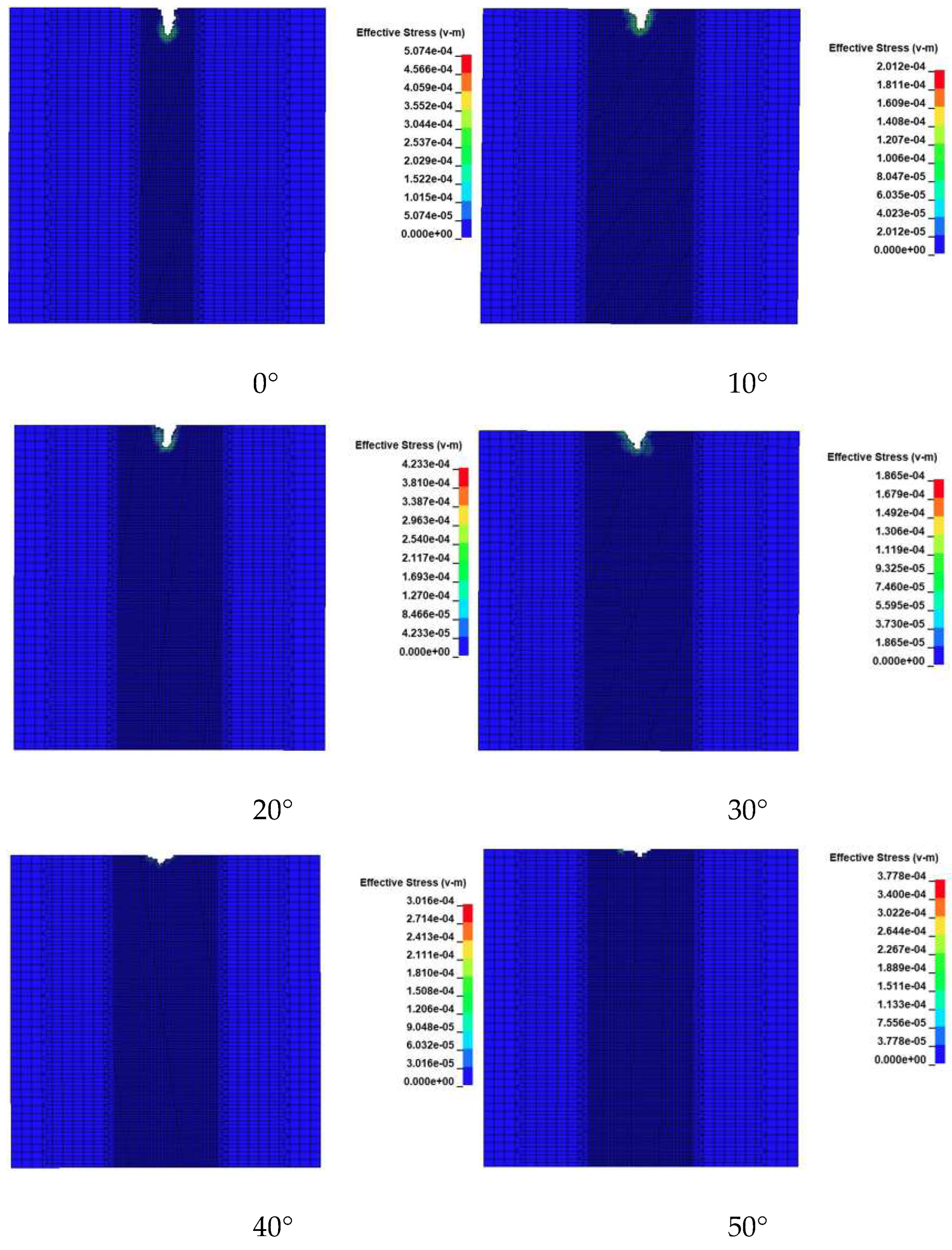
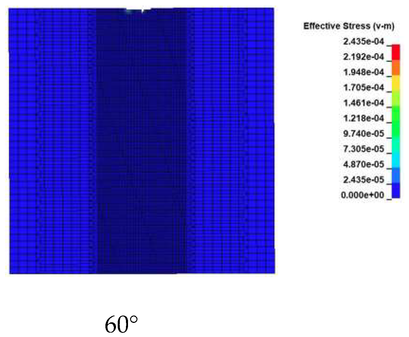
Figure 7.
Shape diagram of crushing pit of jet impact rock at different angles.
Figure 8.
Changes of depth and width of rock breaking by water jet with different dip angles.
Figure 9.
The stress damage diagram of jet impact rock under different diameters.
Figure 10.
Shape of the crater at a jet diameter of 0.7mm.
Figure 11.
Shape of the crater at a jet diameter of 1.0mm.
Figure 12.
Shape of the crater at a jet diameter of 1.3mm.
Figure 13.
Shape of the crater at a jet diameter of 1.6mm.
Figure 14.
Variation of rock breaking width and depth for different nozzle diameters.
Figure 15.
Stress damage diagram for rock impact by jet stream at different velocities.
Figure 16.
Graph of depth of breakage versus water jet velocity.
Figure 17.
Schematic diagram of the rock breaking process model.
Figure 18.
Rock breaking effect of the jet at different speeds for t=400μs.
Figure 19.
Rock breaking pit diagram of different jet bit.
Figure 20.
Comparison of rock breaking effect of different jet bit.
Figure 21.
Rock breaking drilling principle diagram of spin type porous jet bit.

Table 1.
* Mat _ NULL model parameters.
| ρ/kg/m3 | PC/Pa | MU/N·s·m-2 |
|---|---|---|
| 1000 | -10.0 | 0.8684E-3 |
Table 2.
Equation of state parameters of * EOS _ GRUNEISEN.
| C/(m/s) | S1 | S2 | S3 | GAMAO | A | E0/Pa | V0 |
|---|---|---|---|---|---|---|---|
| 1480 | 0.0 | 0.0 | 0.0 | 0.3 | 0.0 | 0.0 | 0.0 |
Table 3.
* Mat _ H-J-C model parameters model parameters.
| 2.4 | 14.86 | 0.048 | 0.79 | 1.6 | 0.007 | 0.61 | 0.85 | -1.71 | 2.079 |
| 0.04 | 1 | 0.004 | 0.016 | 0.8 | 0.001 | 0.1 | 0.01 | 7 | 1 |
Disclaimer/Publisher’s Note: The statements, opinions and data contained in all publications are solely those of the individual author(s) and contributor(s) and not of MDPI and/or the editor(s). MDPI and/or the editor(s) disclaim responsibility for any injury to people or property resulting from any ideas, methods, instructions or products referred to in the content. |
© 2023 by the authors. Licensee MDPI, Basel, Switzerland. This article is an open access article distributed under the terms and conditions of the Creative Commons Attribution (CC BY) license (http://creativecommons.org/licenses/by/4.0/).
Copyright: This open access article is published under a Creative Commons CC BY 4.0 license, which permit the free download, distribution, and reuse, provided that the author and preprint are cited in any reuse.


