Submitted:
17 June 2025
Posted:
17 June 2025
You are already at the latest version
Abstract
Jacking-pipe construction has the advantages of high mechanization, small environmental impact, fast construction speed, etc. It is widely used in the project of underground pipeline under the river. However, jacking-pipe grouting under shallow burial conditions is prone to surface slurry problems. Based on the jacking-pipe project of Meichong Lake in Changfeng County, Hefei, this paper discussed the mechanism of grouting surface leakage, and defined the relationship between the critical pressure of jacking-pipe grouting and the ultimate pressure of shear damage of mud jacket. Mechanical model of surface leakage from shallow buried jacking-pipe grouting was established. A general mathematical expression for the grouting critical pressure was derived and a sensitivity analysis was performed. A numerical model was established based on the background engineering, and multiple sets of grouting pressure conditions for simulation and analysis were set up. The results show that the cohesive force c, the angle of internal friction φ, and the overburden thickness hs are all approximately linearly and positively correlated with the critical pressure of grouting. When the grouting pressure is less than 197.54 kPa the surface settlement increases. When this value is exceeded the surface displacement changes from settlement to uplift and the risk of slurry bubbling increases significantly. The theoretical calculation matches the value of grouting critical pressure from numerical simulation. The actual grouting pressure in the project is lower than the theoretical grouting critical pressure value and no slurry bubbling occurs during construction, which has verified the reliability of the theoretical model. This study can provide theoretical basis and investigation ideas for the setting of reasonable grouting pressure in similar projects.
Keywords:
permeable stratum
; jacking-pipe grouting
; critical pressure
; jacking-pipe slurry
1. Introduction
Crossing of underground pipelines from underneath the river is a common construction during the construction of water supply, drainage, heat and power infrastructures [1,2,3,4,5,6]. Because this construction requires a high degree of mechanization, low environmental impact, fast construction speed, small footprint, etc., the construction of underground pipelines crossing from the river underground often adopts the jacking-pipe scheme [7,8,9]. Pipe-soil friction is an important factor in the constraints of jacking-pipe construction (especially for large jacking-pipe cross sections or long jacking-pipe distances [10]). Resistance-reducing mud is a common way to reduce the frictional resistance between pipe and soil [11,12,13] (forming a mud film around the pipe, changing the pipe-soil contact friction from dry friction to wet friction, which in turn reduces the frictional resistance between pipe and soil of the pipe). When a jacked pipe crosses a river under shallow and ultra-shallow burial conditions, the leakage of slurry from the ground surface is highly likely to be caused if the grouting pressure is not properly controlled [14,15,16]. This can pose a serious threat to the water environment, which not only wastes materials but can also cause serious construction safety accidents [17]. Therefore, it is of great theoretical significance and engineering application value to study the surface leakage of jacking-pipe grouting.
When a jacking-pipe crosses from underneath a river, the stratum being traversed mainly consists of clay, silt, sandy soil, silt and silty soil. Sometimes rock stratum is also encountered by drilling. According to the surface leakage mechanism of jacking-pipe grouting, the traversed stratum can be categorized into four types: viscous confined stratum, permeable stratum, fissure leakage stratum and rocky stratum [18]. In this case, the permeable stratum consists mainly of sandy, chalky type soils or gravelly soils with large particles. Permeable stratum has high porosity ratios due to weak inter-particle connections and large pores (especially in slightly dense or less dense soils). The diffusion stages of slurry are mainly categorized into filling diffusion, penetration diffusion, compression diffusion [19] and splitting diffusion. These four diffusion modes can occur simultaneously or sequentially during the actual construction process [20]. Slurries for jacking-pipe grouting in permeable stratum usually gradually fill the pore space and percolate along it [21,22,23]. At this point Darcy's law can be adapted. When the grouting pressure reaches a certain value, the slurry may penetrate to the surface along the pores, which is manifested as infiltration damage.
Li Chunlin [24] introduced a safety factor to derive the optimal grouting pressure. However, this study did not discuss the maximum grouting pressure value. In this paper, the critical pressure in case of leakage from the jacking-pipe grouting surface was defined, and the prediction model of surface leakage from jacking-pipe grouting in permeable stratum was established. A method for calculating the critical pressure for surface leakage from jacking-pipe grouting in permeable stratum was proposed, and a general mathematical expression for the calculation method was derived. Combined with the actual grouting parameters of the project, the correlation law between each parameter was analyzed. This paper then addressed practical engineering problems.
2. Critical Pressure Prediction Model
2.1. Critical Pressure Definition and Leakage Mechanisms in Grouting Surface
During the synchronized grouting jacking process (shown in Figure 1), thixotropic mud flows out of the grouting holes. Due to the effect of self-weight, the over-excavated voids of the jacking-pipe were filled with thixotropic mud. At this point the disturbed mud takes on a gelatinous consistency, which indicates that this can reduce stratum losses [20]. At the same time, the mud under grouting pressure penetrates into the soil stratum around the pipe. A stratigraphic geotechnical body is an aggregate of solid particles with porous interconnecting features. This interconnected pore feature provides a channel for mud to seep through the stratum. Due to the complexity of the physical properties of the stratigraphic geotechnical body itself, the pore morphology in the geotechnical body is also complex and variable, which causes the infiltration channels to vary greatly from location to location. Slurries are mainly mixtures (dense permeable blocks) composed of solid-phase particles and liquid-phase bodies. When the slurry begins to come into contact with the stratum, the pressure of the slurry acting on the contact surface is greater than the pressure of the water in the stratum. The solid-phase fines and liquid-phase components of the slurry enter the stratum through the infiltration channel, which in turn causes the infiltration channel to silt up. As time goes by, the permeable stratum channels are gradually filled with fine-grained components and many permeable blocks are cemented together. When a certain level of infiltration is reached, the mud no longer spreads and is eventually completely enclosed, forming a mud skin. At this point the static mud takes on a gelatinous consistency, forming a dense, impermeable mud jacket.
The mud jacket blocks the exchange of material between the soil and the mud, which stops the mud from flowing out and fills the over-excavated void around the perimeter of the pipe. Effective stresses and excess pore water pressure induced by jacking-pipe construction could not be dissipated quickly under the closed conditions of the mud jacket. The surrounding soil stratum remains stable under the compacting action of the effective stresses, which prevents excessive surface stratum. Under the protection of the mud jacket, the pipe becomes floating due to mud buoyancy and its effective weight is reduced. At this time, the thixotropic mud converts the dry friction between the pipe and the soil layer into liquid friction, which can reduce the jacking-pipe jacking friction resistance and soil stratum disturbing stratum. In the process of pipe jacking, as the jacking distance increases, the contact area between the pipe and the soil increases, and the friction is greater, which in turn increases the difficulty of construction. Thixotropic mud converts dry friction into liquid friction while filling over-digging voids caused by differences in pipe and pipe-jacking machine dimensions. The grouting pressure generated by the thixotropic slurry supports the soil stratum caused by the soil stress release. Therefore, the thixotropic mud is widely used.
When the leakage channels of the mud in the stratum are closed, the slurry develops an excesshydrostatic pressure, which can cause additional stresses in the stratum. When the additional stress in the stratum reaches a certain level, the stratum will be deformed and damaged. When the stratum breaks down, leakage channels for the mud are formed again. Subsequently, the stratum leakage channels are gradually filled with fine-grained components. Many permeable blocks are bonded together to form a mud jacket, and leakage channels are closed again.
The above process will cycle back and forth in turn. When the leakage channel extends to the surface, it will cause bubbling to occur. It can be seen that the initiating condition for the occurrence of bubbling is the deformation of the stratum and the forming of a new leakage channel. Therefore, whether or not surface bubbling occurs depends primarily on the maximum pressure that the stratum can withstand without damage and the relative magnitude of the mud pressure. Slurry bubbling occurs when the slurry pressure is greater than the critical pressure for stratum damage. Grouting pressure control is the key to preventing surface bubbling under conditions of specific stratigraphic characteristics and well-matched slurry with them.
2.2. Predictive Modeling
The following assumptions were made for the construction of the critical pressure model for surface leakage of shallow buried river crossing jacking-pipe grouting.
1) The slurry pressure is stabilized [25], which means that the pressure loss due to diffusion of the grouting pressure is not considered;
2) The slurry wall is formed over a short period of time, or the slurry wall is stabilized. The strength of the mud film is sufficient, which means that the mud film is a complete seal for the leakage channel until shear damage occurs in the soil;
3) The mud film caused by the slurry is horizontal. The additional stresses attached to the sealing surface by the liquid column are not affected by changes in the depth of the seal.
Based on the above assumed conditions, a microcell of the stratum soil contact surface was taken as shown in Figure 2.
3. Critical Pressure Theory Analysis
3.1. Derivation of Critical Pressure Equation
According to the engineering application, a simplified model was constructed and the following assumptions were made. The hydrostatic pressure of the river was constant and pressure changes due to river flow were ignored. An elastic theoretical formulation was applied to the soil, which was considered as a homogeneous, isotropic, semi-infinite spatial elastic body. When considering the shear stresses of the soil, the effective stresses were involved in the calculation according to the principle of effective stresses, since the upper soil was saturated. The pore water pressure and effective stress are independent of time. The mud wall in the leakage channel is formed in a short period of time and the mud film is strong. The mud film is a complete seal to the leakage channel until shear damage occurs in the soil. Therefore, infiltration consolidation of saturated soils was neglected. The grouting pressure was considered to be a certain stable value, which implied that pressure loss due to instability of the grouting pump pressure or pressure spreading of the slurry in the soil was not taken into account.
A unit was intercepted at a point in the soil for force analysis. The unit was a cube with sides of length and its own gravity was ignored. The unit has a tendency to move upwards under slurry pressure. Thus, there is a downward shear force generated there, as shown in Figure 2a.
The unit body is balanced by forces in the vertical direction:
Here, is the grouting pressure, kN; is the gravity of the upper soil stratum, kN; is the shear force, kN.
It can be further seen that:
Here, is the grouting pressure per unit area, kPa; is the effective stress of saturated soil, kPa; is the lateral shear stress, kPa.
Since the shear stresses within the soil can be carried only by the soil skeleton, the shear strength of saturated soil is related to the effective stress. Equation (3) can be obtained.
Here, is the total stress, kPa; is the pore water pressure, kPa; is the river water gravity, which is approximated to take the gravity of the water, kN/m3; is the saturated gravity of the overburden of the header pipe, kN/m3; is the depth of the river, m; is the distance of the unit from the riverbed, m.
According to the effective stress principle for saturated soils proposed by Terzaghi:
Substituting Equation (4) into Equation (2) will yield:
Substituting Equation (2) and Equation (5) into Equation (1) and simplifying:
Taking the plane stress state as an example, the model was simplified and the stress analysis was performed as shown in Figure 2b. Lateral friction resistance is the static earth pressure. Positive stresses in the horizontal direction resisting the upward movement of the unit:
Here, K is the coefficient of static earth pressure, the value of which can be determined by the empirical formula, , ( is the effective angle of internal friction of the soil).
Positive vertical stress:
According to Equation (6), the tangential stress in the plane:
Tangential stress in the plane:
Based on the stress analysis, the maximum principal stress and the minimum principal stress can be determined from the Mohr stress circle:
The monolith was assumed to be in limiting equilibrium. Calculated using the effective stress intensity index according to the Mohr-Coulomb strength theory:
Here, is the effective cohesive force of the soil, kN/m2. It was obtained by substituting Equation (12) and (13) into Equation (14) and simplifying:
Substituting Equation (6) into Equation (14):
Further:
Obtained from the formula for finding the roots of a quadratic equation:
As a result:
The larger value calculated by Equation (18) is the maximum grouting pressure at any point in the soil layer. At this moment the soil stratum is in a critical state of imminent shear damage. The situation considered here is that the jacking-pipe grouting direction is vertically upward. Then when the soil in contact with the jacking-pipe undergoes shear damage, slurry bubbling occurs in the soil stratum. It can be seen that the critical pressure for surface leakage of shallow buried jacking-pipe grouting is mainly related to the nature of the soil (, , , ) and the depth of the jacking-pipe burial. For rocky stratum, Xu Bin et al. [26] thoroughly investigated the relationship between side pressure coefficient, crack inclination and overburden pressure and grouting pressure.
3.2. Calculation Reasonableness Validation
In order to verify the reasonableness of the above critical pressure derivation results, a comprehensive project in Changfeng County, Hefei City, China, for drainage and flood control as well as rainwater and sewage diversion, was used as a case study to initiate the verification. When the project crosses the Chu River section, the jacking-pipe program adopted mud-water balance construction. The total length of the project site line is 7015m, as shown in Figure 3. The stratigraphic distribution of the project site is, from top to bottom, fill, silty chalky clay, clay, silty clay, strongly weathered mudstone, and weathered mudstone.
According to the actual jacking-pipe engineering of the background project, the thickness of the overlying soil layer of the jacking-pipe, , was taken as 3.0m, and the depth of the river water, , was taken as 3.0m. The jacking-pipe crossed the stratum of silty clay. Its density, , was taken as 1.922kg/m3, cohesion, c, was taken as 40kPa, friction angle, , was taken as 15.5°, and gravitational acceleration, , was taken as 10m/s2. Bringing the above parameters into Equation (15) ~ (18), the results of the calculations are shown in Table 1.
The values used for grouting pressures in the background project were 150kPa-180kPa when crossing the river. According to the results calculated in Table 1, it can be seen that the theoretical maximum grouting pressure (critical pressure) under the condition of this background project is 197.538 kPa. The grouting pressure (150kPa-180kPa) during actual project construction is less than the theoretical critical pressure (197.538 kPa). Engineering data was normal during construction of the river crossing. The jacking-pipe project was completed smoothly and successfully, with good construction quality, and successfully passed acceptance and was put into operation. This can verify the rationality and feasibility of calculating the critical pressure.
4. Numerical Simulation Calculation and Analysis of Jacking-Pipe Grouting Construction
4.1. Numerical Simulation Model Generalization
Based on the background engineering in Section 3.2, the mud-water-balance jacking pipe project was simplified in order to more easily simulate the grouting pressure situation during jacking. The size of the numerical simulation model is 3-5 times the size of the soil surrounding the jacking-pipe project. The length, width and height of the numerical model are 80m × 80m × 60m, as shown in Figure 4a. The stratum was divided into four layers, namely fill (1m), silty chalky clay (1.95m), clay (6.7m) and silty clay (5.4m). The material property parameters for each stratum simulation are shown in Table 2. The material property parameters were sourced from the survey data of the background engineering. The river valley model has a maximum width of 55m, a minimum width of 25m and a height of 9.46m. The depth of water in the river valleys varies between 1-10m during dry and abundant periods. The inner diameter of the mud-water-balanced jacking pipe is 3m and the outer diameter is 3.6m. The thickness of the thin overburden on top of the jacking-pipe is 3m. The material model used for the stratum was the Mohr-Coulomb model with a grid size of 5m. The grid size of the jacking-pipe tunnel is 1m. The contact mode of Boolean calculation was used between the stratum and the excavated tunnel entities and between the various soil strata. Only the upper surface of the model is unconstrained (free surface). Horizontal displacement constraints are applied to the left and right boundaries of the model, and vertical displacement constraints are applied to the lower boundary.
The process of numerical simulation mainly includes initial stress field equilibrium, pipe excavation, grouting pressure application, pipe jacking and pipe sheet application. Firstly, the numerical simulation model was imposed boundary conditions and self-weight. The initial displacement was cleared to zero. The model started the initial stress analysis. Next, the jacking force was applied at the pipe jacking palm surface, and the excavated soil was blunted. Then, the jacking-machine's shell was activated. The jacking-pipe grouting pressure was activated at the same time as the friction force was applied. Subsequently, the shell of the jacking machine was blunted. The jacking pipe was jacked in and the pipe sheet was applied. Finally, the soil of the next pipe section was excavated. The shell of the jacking machine was added. The jacking force, grouting pressure and friction force exerted by the previous pipe section were blunted.
The pipe sheet is reinforced concrete material and the shell of jacking-machine is steel material. Both material models were chosen as elastic models. The material property parameters of sheet and shell are shown in Table 2. The following simplifications and assumptions were made to the model for the focus of the study on grouting pressure:
1) The frontal support pressure during jacking-pipe construction was taken from the lateral static earth pressure at the center point of the excavation surface and applied in the form of a circular uniform load over the entire area of the excavation surface. The frontal digging force of the jacking pipe was taken as 88.5kpa, as shown in Figure 5a.
2) The pipe section material was isotropic linear elastomer and the effect of the joints between the sections was neglected. Pipe-soil friction force exerted on the outer surface of the pipe shell and the inner surface of the soil around the pipe. The friction between the pipe and soil was a certain value and uniformly distributed along the pipe jacking direction. It was realized by setting a coefficient of friction on the contact surfaces. The friction force was taken as 3.5 kPa, as shown in Figure 5b.
3) The mud jacket between the shell and the pipe sheet was simulated using an equivalent layer as shown in Figure 4b. The modulus of elasticity of the equivalent layer was taken as 1/50 of the pulverized silty clay unit and its thickness was taken as 2 cm. By varying the properties of the equivalent layer and the setting of the boundary conditions, the change of soil properties during the grouting process can be simulated. This can enable the simulation of simultaneous grouting during jacking [27]. Grouting pressure is the force acting on the pipe sheet and the soil surrounding the pipe sheet. In the simultaneous grouting process, the slurry, under a certain pressure and with a certain grouting speed, infiltrates through the gap of the soil body. The grouting pressure was distributed equally on the upper and lower surfaces of the equivalent layer and its value was taken as 197.538 kPa as shown in Figure 5c.
4) The initial stresses were considered only the self-weight stresses of the strata. Consolidation settlements of the strata over time were not considered. Groundwater effect was also not considered. Only soil settlement due to the jacking of pipe was considered.
4.2. Calculation of Working Conditions
The jacking-pipe grouting pressure study is closely related to the background project. Surface displacement and deformation monitoring points were arranged on the ground in front of and above the face of the jacking-pipe tunnel along the central axis of the tunnel, perpendicular to the central vertical line of the tunnel and the central vertical line of the face of the jacking-pipe tunnel. In order to get the change regulation of the deformation characteristics of jacking-pipe grouting construction with the volume of the grouting pressure, the coefficient of grouting pressure ratio was introduced, as shown in the following Equation (19).
Here, is the grouting pressure ratio, kPa; is the grouting pressure, kPa; is the initial grouting pressure, kPa.
The initial grouting pressure, , was taken as 197.538kPa. The grouting pressures, , were taken as 0kPa, 79.015kPa, 158.031kPa, 197.538kPa, 296.307kPa, 395.076kPa, 493.845kPa, and 592.614kPa for the simulation analysis as shown in Table 3.
4.3. Analysis of Calculation Results
As shown in Figure 6, the vertical displacement of the soil above the jacking-pipe grouting increases with the increasing of grouting pressure. When the grouting pressure increases to 197.538 kPa, the soil begins to bulge upward. When the grouting pressure continues to increase to 592.614 kPa, the soil bulge deformation continues to grow and large displacement deformation occurs below the river channel. Under grouting conditions, the grouting pressure can support the soil above the jacking-pipe. The slurry fills the void between the jacking-pipe and the soil. As the grouting pressure increases, the slurry exerts greater pressure on the soil around the jacking-pipe wall. When the pressure reaches a certain value, the soil around the jacking-pipe will split. When the grouting pressure is higher and the grouting volume is more, the cracks will also become bigger and even develop to the surface, so that the slurry will flow out of the surface by extending the cracks and produce the phenomenon of slurry bubbling.
The calculation results of the surface deformation of the river bottom at the center of the river perpendicular to the jacking-pipe axis cross-section are shown in Figure 7. The vertical displacement of the ground surface gradually decreases with the rising displacement of the grouting pressure. At the jacking-pipe grouting pressure less than 197.538kPa, the maximum vertical displacement of the ground surface above the jacking pipe is manifested as settlement. At the same time, the amount of deformation shows a linear increasing trend, but the amplitude of the increase is small. When the grouting pressure is greater than 197.538 kPa, with the change of the applied grouting pressure, the soil displacement deformation gradually changes from settlement to bulging, and the displacement value is getting bigger and bigger. When the grouting pressure is less than the critical pressure, the vertical displacement of the ground surface shows the phenomenon of settlement, and the settlement value appears to peak and then begins to become smaller. This result is basically consistent with the numerical regularity of surface displacement detection of jacking-pipe in Line 1 and Line 3 by Ren Dongjie et al. [28]. However, the results of Ren Dongjie's study show that the peak occurs at 3/5 of the total jacking distance, not at 1/2 of the total jacking distance. This is because Ren Dongjie's background project crosses two rivers. This background project crossed a shallow river and then a deep river. At the same time, the background project had a jacking distance of up to 150m.
The vertical displacement of the ground surface above the axial direction of the jacking-pipe under different grouting pressures is shown in Figure 8. It can be seen that the vertical displacement of the soil above the axial direction of the jacking-pipe is settlement when the grouting pressure is less than 197.538kPa. When the grouting pressure is greater than 197.538kPa, the displacement of the soil body gradually changes from settlement to bulge, and the value of bulge rises sharply with the increase of the grouting pressure. When the grouting pressure is small, the grouting pressure disturbs the soil less. Higher grouting pressures result in a gradual change from settlement to uplift of the surface soil.
The maximum values in the surface vertical displacement under different grouting pressures in Figure 8 were selected to plot the maximum vertical displacement of the surface versus the grouting pressure, as shown in Figure 9. As shown in Figure 9, the maximum vertical displacement of the ground surface above the jacking-pipe axial direction keeps getting larger as the grouting pressure increases. The maximum displacement value is significantly maximized when the grouting pressure is greater than 250 kPa. The reason for this is that the action of the grouting pressure causes the grouting layer between the pipe and the soil to be squeezed and deformed. Increasing the grouting pressure can play a role in compacting the stratum around the pipe section and reducing the settlement of the soil stratum. However, as the jacking-pipe grouting pressure is increasing, the soil displacement and deformation above the jacking-pipe will increase. Therefore, in the construction of thin-covered, large-diameter, mud-water-balanced and river-crossing pipe jacking, attention should be paid to controlling the size of the jacking pipe grouting pressure to make the best grouting control effect.
5. Discussion
According to the analytical derivation of the critical pressure in Section 3.1, it can be seen that the critical pressure of surface leakage of synchronized grouting for river crossing and shallow buried pipe jacking construction is related to the cohesive force , the angle of internal friction , the thickness of the overburden and other factors. The parameter sensitivity of the theoretical solution was analyzed with reference to the construction parameters of mud-water-balance jacking-pipe across Chu River in Changfeng County, Hefei City. When studying the law of distribution of the critical pressure as a function of a factor, only the magnitude of this parameter was varied and all other parameters were assumed to remain constant. When the cohesive force is at 20~600kPa (20, 40, 60, 80, 100, 150, 200, 250, 300, 400, 500, 600), the angle of internal friction is at 5~30º (5, 10, 15, 20, 25, 30), and the thickness of overburden is in the range of 1.0~10.0m (1, 2, 3, 4, 5, 6, 7, 8, 9, 10), the surface leakage critical pressure variation characteristics are shown in Figure 10.
As can be seen in Figure 10, with the increase of the cohesive force , and the angle of internal friction and the thickness of overburden , surface leakage critical pressure are showing an increasing overall change rule. These three parameters have a clear linear relationship with the surface leakage critical pressure . This paper has some limitations. Ma Minglei et al. [27] not only discussed the settlement changes of the ground surface under different grouting pressures, but also revealed the jacking deformation law of circular reinforced concrete pipe under different grouting. Their results showed that with the increase of grouting pressure, the deformation of the upper and lower part of the reinforced concrete circular pipe gradually increased. After the increase of grouting pressure to a certain degree, it did not change much. For the awful construction conditions, Yang Xian et al. [29] developed a special grouting slurry formulation to improve the slurry properties. These research results can be a good addition to the content of this paper.
6. Conclusions
Based on the Hefei Changfeng County Meichong Lake jacking-pipe project, we have reached some major conclusions about the critical pressure of surface leakage for shallow buried jacking-pipe grouting underwater.
(1) The mechanism of action of jacking-pipe grouting pressure during construction was discussed. At the same time, the slurry bubbling mechanism of jacking-pipe construction was described. The occurrence of slurry bubbling depends primarily on the maximum pressure that the formation can withstand before a damage occurs, and the relative magnitude of the slurry pressure. The theoretical calculation model of jacking-pipe grouting pressure for large-diameter, mud-water-balanced jacking-pipe with thin cover was constructed, and the general mathematical expression for the maximum grouting pressure was derived.
(2) Numerical simulations were performed to calculate the working conditions of jacking-pipe grouting under different grouting pressures, and the surface displacement and deformation values under different grouting pressures were analyzed. As the jacking-pipe grouting pressure increases, the vertical displacement and deformation of the soil above the jacking pipe increases. When the jacking-pipe grouting pressure increased to 197.538 kPa, the displacement of the soil above the jacking-pipe manifested itself as a bulge. The vertical displacement of the ground surface above the axial direction of the jacking-pipe gradually decreases with the rising of the grouting pressure. When the jacking-pipe grouting pressure increases to 197.538 kPa, the manifestation of the maximum vertical displacement of the ground surface above the axial direction of the jacking-pipe changes from settling to bulging.
(3) This study revealed the influence law of grouting pressure on the stability of jacking-pipe grouting construction in thin overburden, mud-water-balance and river crossing pipes. The regularity of the critical grouting pressure with the property of the stratum was investigated, and the influence of the property of the stratum on the critical grouting pressure was plotted. This study provides a theoretical basis for the reasonable setting of jacking-pipe grouting pressure in the construction of river crossing jacking-pipe with mud-water balance in thin overburden.
Author Contributions
Conceptualization, Z.Z. and Y.H.; Data curation, X.L. and F.C.; Methodology, Z.Z. and X.L.; Formal analysis, Z.Z. and Y.H.; Investigation. Y.H. and W.L.; Writing—original draft, Z.Z. and Y.H.; Writing—review & editing, Z.Z. and X.L.; Supervision, Z.Z and L.W.; Project administration, Z.Z. and X.L.; Resources, Z.Z, X.L. and L.W; Supervision, Z.Z. and L.W.; Validation, M.Z. and Y.H.; Visualization, M.Z. and Y.H. All authors have read and agreed to the published version of the manuscript.
Funding
This study was funded by the Science and Technology Plan of Housing and Urban-Rural Construction in Anhui Province (2022-YF096), and Science and technology development project (HYB20250019, HYB20250012).
Data Availability Statement
The data used to support the findings of this study are available from the corresponding author upon request.
Conflicts of Interest
The authors declare that they have no conflicts of interest.
References
- J. Wang, K. Wang, T. Zhang, S. Wang, Key aspects of a DN4000 steel pipe jacking project in China: A case study of a water pipeline in the Shanghai Huangpu River, Tunnelling and Underground Space Technology. 2018, 72, 323-332. [CrossRef]
- H. Zhou, H. Wang, S. Huang, B. Ma, P. Ma, Key Techniques for the Ultra-Deep Large Flood Diversion Pipeline: A Case Study of Jinshui River Flood Diversion Project in Zhengzhou, Water (Switzerland). 2025, 17(1). [CrossRef]
- Y. Wan, M. Khwaja, M.S. Schultz, G. Bold, W. Simcoe, Tunneling to Manage Construction Impacts for Albany’s Beaver Creek Clean River Project, Albany, New York, 2021 Rapid Excavation and Tunneling Conference, RETC 2021, June 13, 2021 - June 16, 2021, Society for Mining, Metallurgy and Exploration, Las Vegas, NV, United states, 2021, pp. 61-68.
- G. Li, C. Yang, P. Pan, W. Zhang, Record setting 3,300-m distance by horizontal directional drilling of a 711-mm-diameter pipeline crossing the Yangtze River, Journal of Pipeline Systems Engineering and Practice. 2017, 8(1). [CrossRef]
- J.A.e. Sousa, A. Negro, M.M. Fernandes, A.S. Cardoso, Three-Dimensional Nonlinear Analyses of a Metro Tunnel in São Paulo Porous Clay, Brazil. 2011, 137(4), 376-384. [CrossRef]
- Qian, D.; Jiao, H.; Li, Z.; Zhu, Y.; Liu, J.; Chen, Z.; Gao, X.; Liu, H.; Tao, B.; Xu, Z. Ground Settlement Law, Jacking Force Prediction, and Control Countermeasures for Large-Section Rectangular Pipe Jacking of National Highway Underpass. Sustainability 2023, 15, 12888. [Google Scholar] [CrossRef]
- L. Deng, J. Chen, W. Fan, Y. Li, L. Shi, The Dynamic Response Characteristics of a Water Transmission Pipe Crossing a Loess Fault Using a Large-Scale Shaking Table Test: A Case Study, International Journal of Geomechanics. 2024, 24(2). [CrossRef]
- S. Zhou, G.-L. Ye, L. Han, W. Jian-Hua, Key Construction Technologies for Large River-Crossing Slurry Shield Tunnel: Case Study, Journal of Aerospace Engineering. 2021, 34(2). [CrossRef]
- X.-B. Ji, W. Zhao, P. Jia, L.-b. Qiao, M. Barla, P. Ni, L. Wang, Pipe Jacking in Sandy Soil Under a River in Shenyang, China, Indian Geotechnical Journal. 2017, 47(3), 246-260. [CrossRef]
- Z. Wang, J. Wang, D. Fan, T. Liu, Y. Tan, Parameters Analysis of Long-Distance Rectangular Pipe Jacking Underneath Beijing-Hangzhou Grand Canal, Tunnel Construction. 2024, 44, 159-167. [CrossRef]
- K. Wu, L. Mu, L. Hu, L. Zhang, Numerical Analysis of Friction Reduction of Grouting in Long-Distance Pipe Jacking, Applied Sciences (Switzerland). 2025, 15(4). [CrossRef]
- P. Chen, X. Liu, Z. Deng, N. Liang, L. Du, H. Du, Y. Huang, L. Deng, G. Yang, Study on the pipe friction resistance in long-distance rock pipe jacking engineering, Underground Space (China). 2023, 9, 173-185. [CrossRef]
- A. Qannadizadeh, P.T. Shourijeh, A. Lashkari, Laboratory investigation and constitutive modeling of the mechanical behavior of sand-GRP interfaces, ACTA GEOTECHNICA. 2022, 17(10), 4253-4275. [CrossRef]
- H. Shimada, S. Khazaei, K. Matsui, Small diameter tunnel excavation method using slurry pipe-jacking, Geotechnical & Geological Engineering. 2004, 22(2), 161-186. [CrossRef]
- T. Kasper, G. Meschke, On the influence of face pressure, grouting pressure and TBM design in soft ground tunnelling, Tunnelling and Underground Space Technology. 2006, 21(2), 160-171. [CrossRef]
- F. Ye, T. Yang, J.-h. Mao, X.-z. Qin, R.-l. Zhao, Half-spherical surface diffusion model of shield tunnel back-fill grouting based on infiltration effect, Tunnelling and Underground Space Technology. 2019, 83, 274-281. [CrossRef]
- H.-M. Lyu, W.-J. Sun, S.-L. Shen, A. Arulrajah, Flood risk assessment in metro systems of mega-cities using a GIS-based modeling approach, Science of The Total Environment. 2018, 626, 1012-1025. [CrossRef]
- L.S. YE Fei, XIA Tianhan, SU Enjie, HAN Xingbo, ZHANG Caifei Compaction-fracture diffusion model for backfill grouting of shield tunnels in low permeability strata, Chinese Journal of Geotechnical Engineering. 2023, 45(10), 2014-2022. [CrossRef]
- K. Soga, S.K.A. Au, M.R. Jafari, M.D. Bolton, Laboratory investigation of multiple grout injections into clay. 2004, 54(2), 81-90. [CrossRef]
- D. Zhang, Q. Fang, H. Lou, Grouting techniques for the unfavorable geological conditions of Xiang'an subsea tunnel in China, Journal of Rock Mechanics and Geotechnical Engineering. 2014, 6(5), 438-446. [CrossRef]
- J. Liu, H. Cheng, H. Cai, X. Wang, D. Feng, Design and Analysis of Grouting Pressure in Slurry Pipe Jacking Based on the Surrounding Soil Stability Mechanical Characteristics, Geofluids. 2022, 2022, 1-17. [CrossRef]
- H. Shimada, T. Sasaoka, S. Khazaei, Y. Yoshida, K. Matsui, Performance of Mortar and Chemical Grout Injection into Surrounding Soil When Slurry Pipe-jacking Method is Used, Geotechnical & Geological Engineering. 2006, 24(1), 57-77. [CrossRef]
- S. Khazaei, H. Shimada, T. Kawai, J. Yotsumoto, K. Matsui, Monitoring of Over Cutting Area and Lubrication Distribution in a Large Slurry Pipe Jacking Operation, Geotechnical & Geological Engineering. 2006, 24(3), 735-755. [CrossRef]
- C. Li, Simplified Algorithm for Grouting Pressure and Grouting Quantity in Shield Construction, International Journal of Civil Engineering. 2020, 18(4), 419-428. [CrossRef]
- L. Jie, Analysis of the mud escaping of HDD and R&D for preventing mud escaping software, M.Eng. thesis. China University of Geosciences. 2009.
- Xu, B.; Dong, S.; Yin, S.; Li, S.; Xu, Y.; Dai, Z. Analysis of Crack Initiation and Propagation Thresholds of Inclined Cracks under High-Pressure Grouting in Ordovician Limestone. Energies 2021, 14, 360. [CrossRef]
- M. Ma, L. Han, Y. Wu, Q. Li, Y. Zhang, Behavioral Investigations of Three Parallel Large Reinforced Concrete Circular Pipes with the Construction of Pipe Jacking, Applied Sciences. 2023, 13(15). [CrossRef]
- D.-J. Ren, Y.-S. Xu, J.S. Shen, A. Zhou, A. Arulrajah, Prediction of Ground Deformation during Pipe-Jacking Considering Multiple Factors, Applied Sciences. 2018, 8(7). [CrossRef]
- X. Yang, Y. Liu, C. Yang, Y. Chen, Research on the Slurry for Long-Distance Large-Diameter Pipe Jacking in Expansive Soil, Advances in Civil Engineering. 2018, 2018(1). [CrossRef]
Figure 1.
The synchronized grouting jacking process.
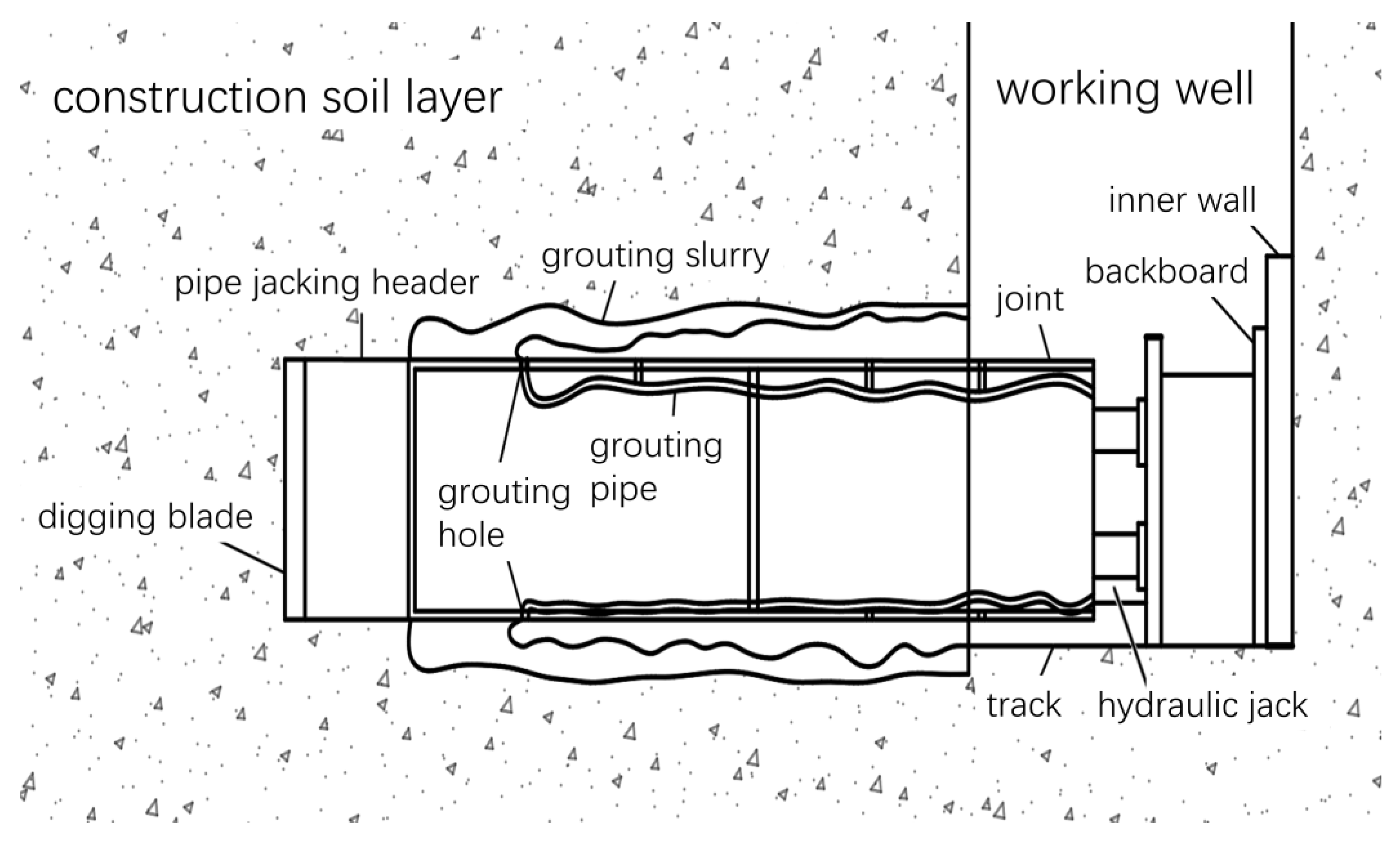
Figure 2.
Force analysis model: (a) forces of unit; (b) plane state of stress.
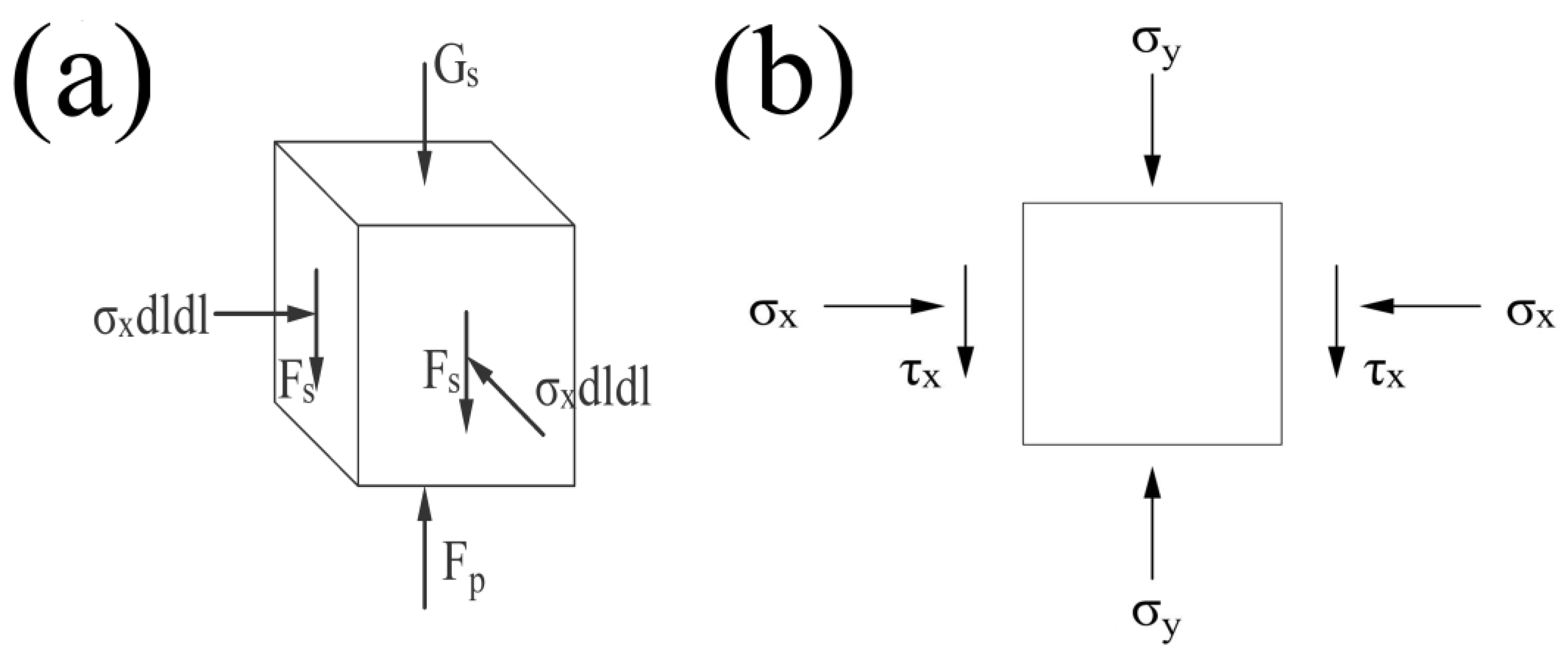
Figure 3.
Project site: (a) top view of the project; (b) plan of the project.
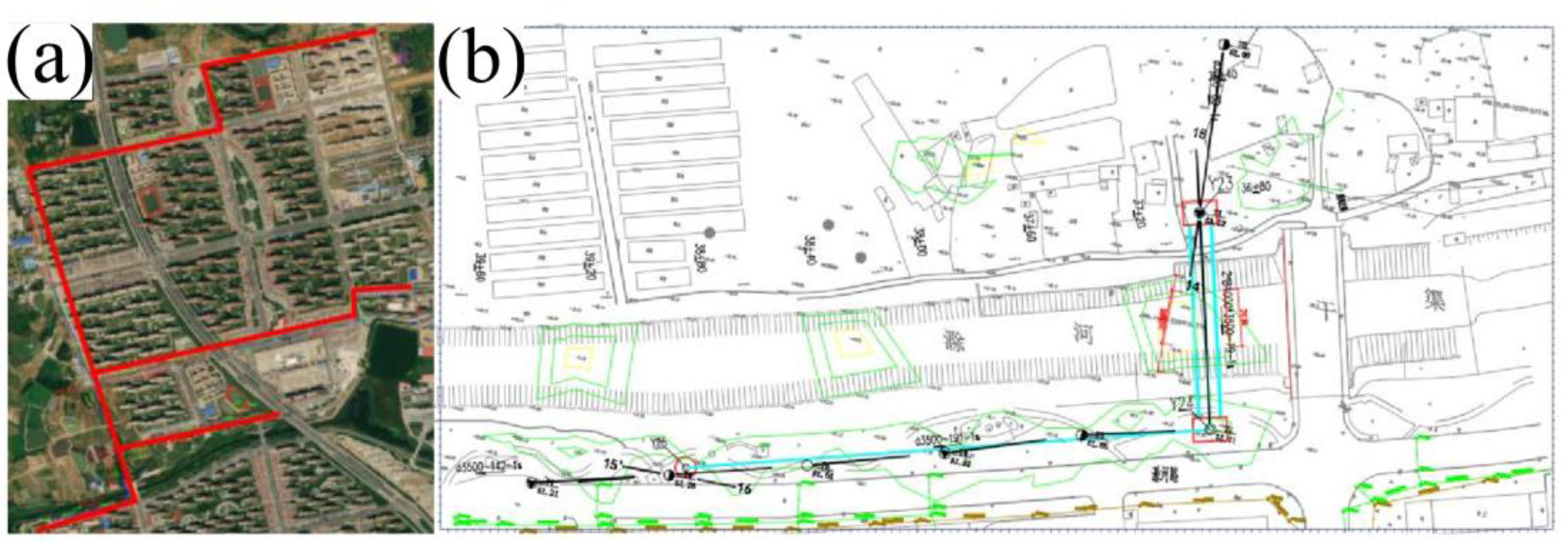
Figure 4.
Numerical simulation model for jacking-pipe with mud-water balance: (a) simulation model; (b) equivalent layer.
Figure 4.
Numerical simulation model for jacking-pipe with mud-water balance: (a) simulation model; (b) equivalent layer.
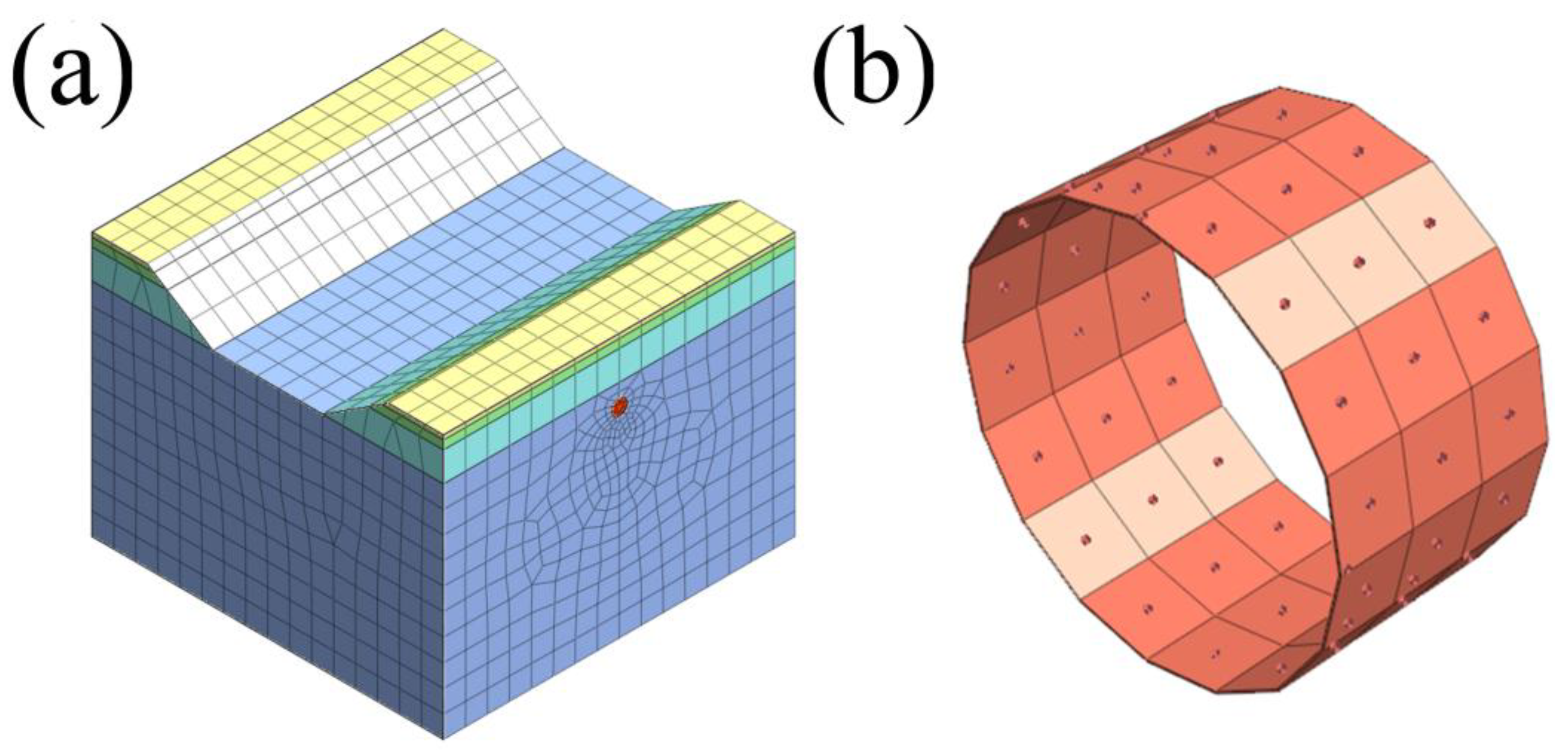
Figure 5.
Numerical simulation assumptions: (a) frontal support pressure; (b) pipe-soil friction force; (c) grouting pressure.
Figure 5.
Numerical simulation assumptions: (a) frontal support pressure; (b) pipe-soil friction force; (c) grouting pressure.
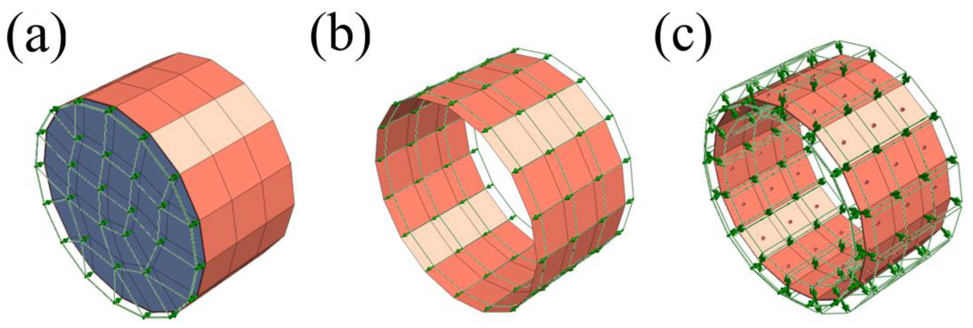
Figure 6.
Clouds of soil vertical displacement under different grouting pressures: (a) 0kPa; (b) 79.015kPa; (c) 158.031kPa; (d) 197.538kPa; (e) 296.307kPa; (f) 395.076kPa; (g) 493.845kPa; (h) 592.614kPa.
Figure 6.
Clouds of soil vertical displacement under different grouting pressures: (a) 0kPa; (b) 79.015kPa; (c) 158.031kPa; (d) 197.538kPa; (e) 296.307kPa; (f) 395.076kPa; (g) 493.845kPa; (h) 592.614kPa.
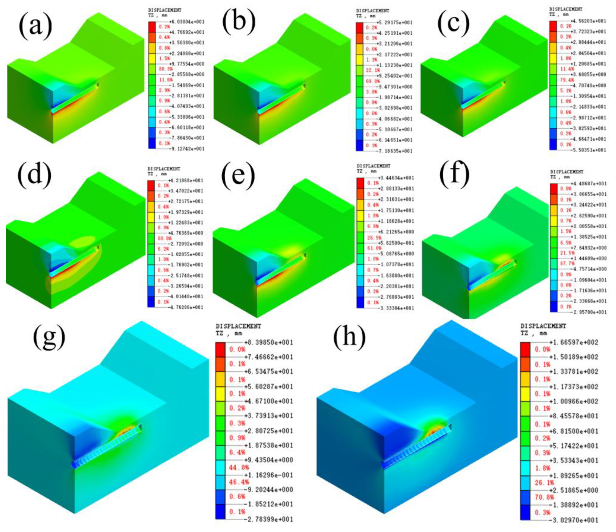
Figure 7.
Vertical displacement plot of the ground surface under different grouting pressures.
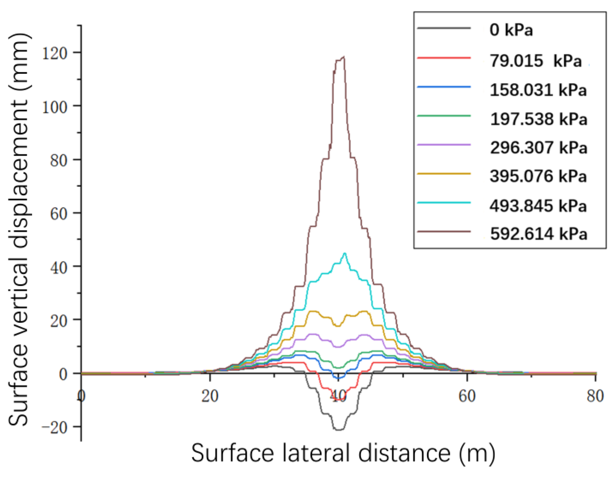
Figure 8.
Vertical displacement of the ground surface in the axial direction of the jacking-pipe at different grouting pressures.
Figure 8.
Vertical displacement of the ground surface in the axial direction of the jacking-pipe at different grouting pressures.
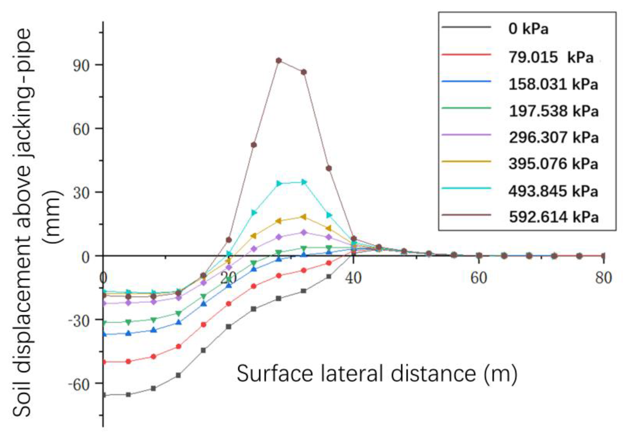
Figure 9.
Relationship between grouting pressure and maximum vertical displacement of the ground surface.
Figure 9.
Relationship between grouting pressure and maximum vertical displacement of the ground surface.
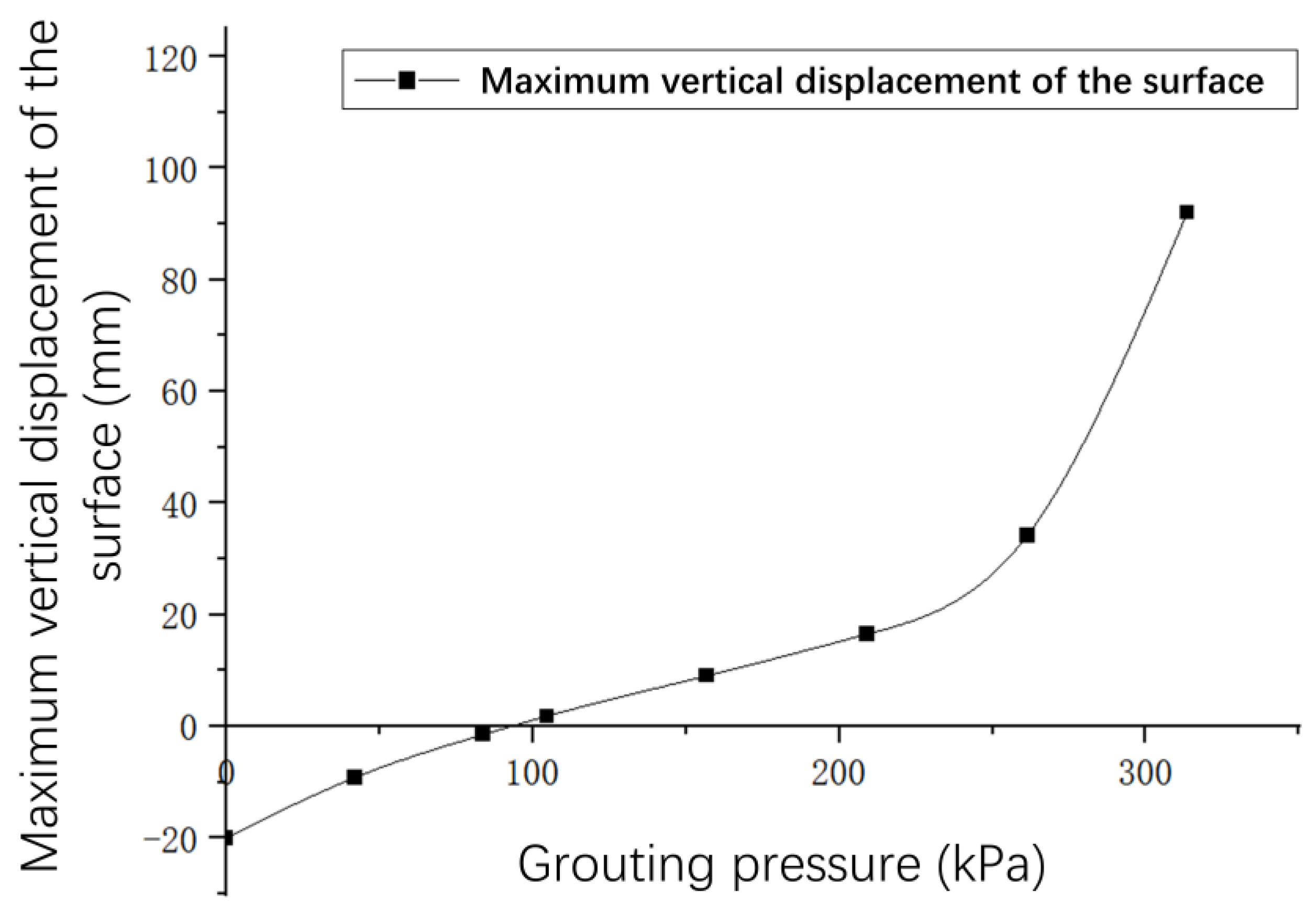
Figure 10.
Sensitivity analysis of surface leakage critical pressure for synchronized jacking-pipe grouting: (a) the cohesive force ; (b) the angle of internal friction ; (c) the thickness of overburden .
Figure 10.
Sensitivity analysis of surface leakage critical pressure for synchronized jacking-pipe grouting: (a) the cohesive force ; (b) the angle of internal friction ; (c) the thickness of overburden .
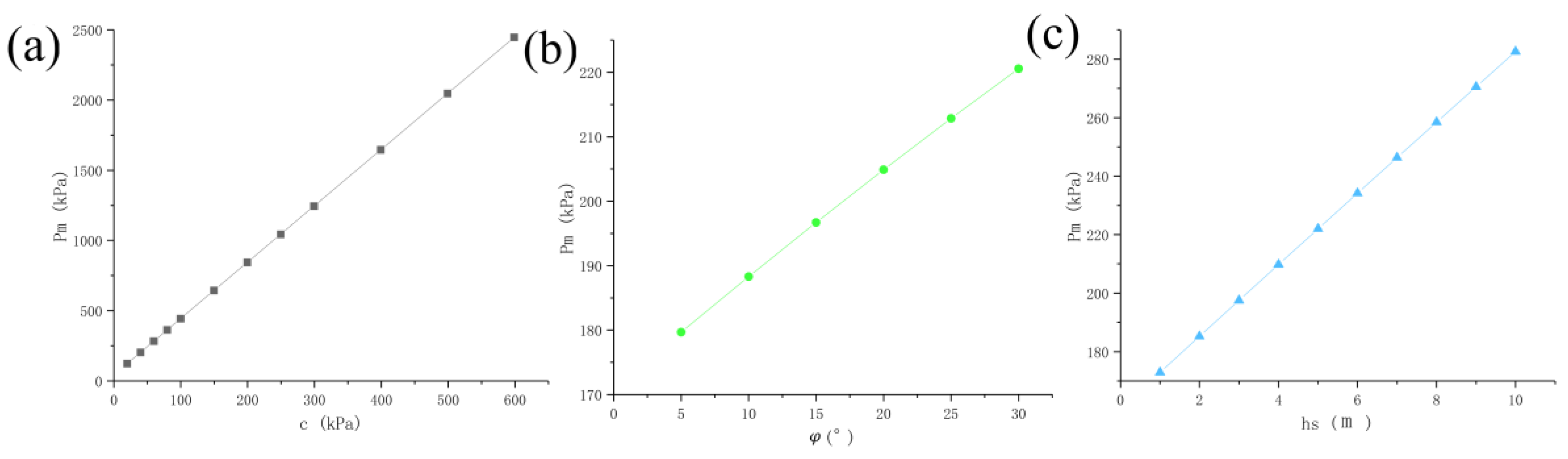

Table 1.
Calculated parameters and results.
| Calculated parameters |
value | Calculated results | value |
|---|---|---|---|
| 40 kPa | 0.733 | ||
| 15.5° | 27.66 | ||
| 3 m | 77.09 | ||
| 1.922 kg/m3 | 134811.105 | ||
| 19.22 kg/m3 | 197.538 |
Table 2.
The material property parameters.
| Parameter type | Elastic modulus E/(MPa) |
Poisson’s ratio μ |
Volumetric weight γ/(kN/m3) |
Cohesive force c/(kPa) |
Angle of internal friction φ/(°) |
|---|---|---|---|---|---|
| Fill | 8.0 | 0.27 | 18.00 | 10 | 10.0 |
| Silty chalky clay | 3.2 | 0.27 | 17.52 | 6.2 | 5.8 |
| Clay | 11.9 | 0.25 | 19.22 | 69.1 | 16.9 |
| Silty clay | 11.3 | 0.25 | 19.22 | 39.3 | 15.5 |
| pipe sheet | 28000 | 0.2 | 23.0 | - | - |
| jacking-machine's shell | 206000 | 0.3 | 78.5 | - | - |
Table 3.
Grouting pressure calculation condition.
| grouting pressure ratio p |
grouting pressure P(kPa) |
grouting pressure ratio p |
grouting pressure P(kPa) |
|---|---|---|---|
| 0 | 0 | 1.5 | 296.307 |
| 0.4 | 79.015 | 2.0 | 395.076 |
| 0.8 | 158.031 | 2.5 | 493.845 |
| 1.0 | 197.538 | 3.0 | 592.614 |
Disclaimer/Publisher’s Note: The statements, opinions and data contained in all publications are solely those of the individual author(s) and contributor(s) and not of MDPI and/or the editor(s). MDPI and/or the editor(s) disclaim responsibility for any injury to people or property resulting from any ideas, methods, instructions or products referred to in the content. |
© 2025 by the authors. Licensee MDPI, Basel, Switzerland. This article is an open access article distributed under the terms and conditions of the Creative Commons Attribution (CC BY) license (http://creativecommons.org/licenses/by/4.0/).
Copyright: This open access article is published under a Creative Commons CC BY 4.0 license, which permit the free download, distribution, and reuse, provided that the author and preprint are cited in any reuse.


