

Submitted:
27 June 2023
Posted:
28 June 2023
You are already at the latest version
Abstract
The pre-chamber technologies can improve the ignition performance of IC engines by more than two orders in magnitude and thereby substantial economic benefits. Compared with the common pre-chamber, a plug-and-play passive scheme is suitable for quick retrofit, which is getting more attention from the automobile industry. Good scavenging is the precondition for improving turbulent jet ignition performance for a passive pre-chamber. Therefore, detailed evaluations of the scavenging process and turbulent jet ignition deserve investigations for new pre-chamber schemes. In this paper, the effects of design parameters on ignition processes of plug-and-play passive pre-chamber were numerically studied, allowing for the lateral angle, orifice diameter, and vertical angle design. Seven pre-chamber schemes were evaluated, and four optimal ones were selected for bench tests. The characteristics of the scavenging process, turbulent jet ignition, and main-chamber combustion were investigated and analyzed. The results show that allowing for the trade-off between ignition energy and scavenging efficiency, the volume ratio of the pre-chamber to clearance is recommended to be 0.2~0.7%, and the corresponding area-volume ratio is 0.003~0.006 mm-1. Compared with the original natural gas engine, the pre-chamber retrofit can save up to 13.2% fuel consumption, which presents a significant improvement in fuel economy.
Keywords:
Natural gas engine
; Turbulent jet ignition
; Pre-chamber
; Scavenging
; Fuel consumption
1. Introduction
Although the Internal Combustion (IC) engine market and regulations conflict on most occasions, their pursuit of fuel economy is consistent but with different motivations. The market tends to be attracted by competitive operating costs, while regulations focus more on emission reductions. Natural gas is the most promising alternative fuel because of its cheapness and environmental protection. However, limited by stoichiometric operation and knocking, natural gas engines suffer significant challenges in improving thermal efficiency.
The knocking is an abnormal combustion phenomenon in Spark Ignition (SI) engines, which is caused by the spontaneous ignition of the end-gas mixtures before the arrival of primary flames. The knocking can significantly reduce combustion performance and engine reliability. Until now, many methods have been proposed for knocking inhabitation but at the expense of fuel economy for sacrifice [1, 2]. Due to the low laminar flame speed, natural gas tends to occur end-gas autoignition and thereby knocking combustion at stoichiometric operation. On the other hand, lean burning technology can not only alleviate knocking issues but also improve thermal efficiency and pumping loss [3]. Although the lean-burning concept is widely used in ships, however, construction machinery, power generation equipment, and road vehicles still have to operate under stoichiometric conditions due to the requirement of after-treatment systems [4].
Improving the ignition performance and accelerating flame propagation can mitigate knocking and increase the lean-burning limit (if allowed). Compared with traditional single-point spark ignition, space ignition has a higher ignition energy and shorter flame traveling distance, leading to improved flame speed, efficiency, and stability. Pre-chamber ignition, also namely turbulent jet ignition, is the most promising space ignition system. Unlike conventional spark ignition, the turbulent jet ignition process is more complex, involving (a) the scavenging, ignition, and flame propagation in the pre-chamber, (b) the quenching and ejection at the nozzle, and (c) the ignition and flame propagation in the main chamber, sequentially. Due to the reduced fuel fraction and turbulent kinetic energy levels [5], the early combustion phase of turbulent jet ignition is longer than that of spark ignition for the pre-chamber. However, as combustion proceeds, the combustion duration of turbulent jet ignition can be shortened by 30~50% [6], featuring advanced combustion phasing and increased cylinder pressure. To further shorten the early combustion phase, some laboratory studies have integrated an auxiliary fuel injector for the pre-chamber, called the active pre-chamber [7]. However, to meet the immediate retrofit needs of traditional spark plugs, the plug-and-play passive pre-chamber is still the preferred solution in the industry.
Numerous studies have been published on the concept, design, and operation of plug-and-play passive pre-chamber ignition systems. The primary investigations are focused on the flow, heat transfer, scavenging [8], jet ejection [9], flame propagation [10], etc. The design of the pre-chamber ignition system is the most important in the industry, including the pre-chamber shape [11], volume [12], nozzle [13], auxiliary fuel injection [14], and the main chamber retrofit [15]. Based on engine test measurements, different operating conditions, such as low load [16], cold start [17], exhaust gas recirculation [18], and Miller cycle [19], are evaluated to improve pre-chamber performance. However, considering the significant difference between cold scavenging and hot jet ignition, a comprehensive evaluation is still necessary for engineering applications, especially for natural gas engines. Therefore, it is required to conduct novel research to reveal the interaction of key design parameters for engine product improvement.
In this paper, the influence of nozzle design on the plug-and-play passive pre-chamber of a natural gas engine was studied by multi-dimensional numerical simulations, and the performance of the pre-chamber retrofit was evaluated by an engine bench test. The most crucial nozzle design parameters were determined, including the lateral angle, vertical angle, and orifice diameter. Different combustion stages were identified in the pre-chamber and main chamber ignition. The mechanism and sensitivity of the design parameters to each stage were analyzed. The economic benefits of the pre-chamber retrofit are confirmed, and suggestions for the passive pre-chamber design are provided.
2. Methodology and Specification
2.1. Test Cases
The nozzles connecting the pre-chamber and main chamber affect the scavenging and ejection processes significantly. The critical parameters of the nozzle include orifice diameter, number, and lateral/vertical angle. The orifice diameter and number together affect the ratio of the total orifice cross-sectional area to the pre-chamber volume, i.e., the area-volume ratio. Previous studies have shown that the scavenging and flow characteristics of pre-chambers with the same area-volume ratio are similar [6]. An obvious inference is that no matter whether the parameter to be changed is the orifice diameter or the orifice number, the goal is to search for the optimal area-volume ratio. Therefore, the orifice number constant remains while the effects of orifice diameter and other vital parameters are investigated.
Figure 1 is the structural diagram of the pre-chamber. The pre-chamber has a cylinder with an inner diameter of 9.6 mm and a volume of 1500 mm3, which is threaded to fit a standard spark plug. To facilitate rapid replacement without modifying the cylinder head, the plug-and-play pre-chamber is designed to match the cavity originally intended for spark plugs, which enables seamless integration between the pre-chamber and the combustion chamber. The nozzle adopts a 5-orifice design, including four circumferential orifices and one central orifice. Nozzle design parameters include orifice diameter d, vertical angle α, and lateral angle β. The test cases are shown in Table 1. Based on case 1 with the best economy, the other six cases are also designed to study the effects of d, α, β on scavenging, ejection, and combustion performance.
2.2. Experimental Setup
The bench test was carried out on the natural gas engine WP15NG mass-produced by Weichai Power Co., Ltd. The test engine specifications are shown in Table 2. The in-line 6-cylinder engine adopts a turbocharger, intercooler, and exhaust gas recirculation, maintaining stoichiometric combustion through the electronic control unit. A direct current dynamometer is used to control engine speed and torque. Natural gas consumption, intake flow, and air-fuel ratio are closed-loop controlled by INCA software. Six Kistler piezoelectric sensors measure the pressure signals in the respective cylinder with a crank angle resolution of 0.1°CA. More information on the test bench can be found in the literature [25,26]. Benefiting from the plug-and-play design of the passive pre-chamber, the quick retrofit of different schemes improves the efficiency of test evaluation. To mimic realistic natural gas, the fuel mixture contains 72.4% N2, 19.0% O2, 4.6% CH4, 2.2% CO2, and 1.8% H2O in mass fraction.
According to the Worldwide Harmonized Heavy-Duty Vehicles Test Procedure, operating conditions of the six-cylinder commercial vehicle engine were selected, as shown in Table 3, with 1100 rpm and 2000 N·m representing the typical operating condition. The sensitivity of different pre-chamber configurations to operating conditions can be evaluated by varying engine speed and load. Cylinder pressure signals were recorded with 0.1° crank angle resolution and averaged over 50 consecutive engine cycles. Combustion duration was defined as the crank angle difference between 10% and 90% of the mass fraction burned.
2.3. Numerical Model and Calibration
Based on the boundary conditions provided by the one-dimensional simulation software GT-POWER, this study uses the three-dimensional computational fluid dynamics software CONVERGE to describe the flow, heat transfer, and combustion phenomena. The spatial discretization of the transport equations adopts the second-order upwind numerical scheme. The time integration takes the implicit format, with the time step determined by the Courant-Friedrichs-Lewy condition. The PISO algorithm is used for the pressure-velocity coupling. On the other hand, the RNG k-ε model is used for turbulence simulation because it is effective and can reproduce the statistically averaged flow patterns of the LES model [27]. The ignition process adopts the source/sink model, releasing 40 mJ of ignition energy in each cycle. Figure 2 shows the computational domain, of which the hybrid meshing process uses adaptive refinement to capture temperature and velocity gradients. The grid independence verification shows that when the elemental size is below 4 mm, the cylinder pressure becomes consistent. The G-Equation models the flame dynamics, and the laminar flame velocity is corrected to match the experimental cylinder pressure and heat release rate curves.
3. Results and Discussion
3.1. Influence of Nozzle Design on Scavenging
Scavenging refers to the removal and remixing process of residual gas in the pre-chamber, while its effect on heat transfer is equally noteworthy. Ideal scavenging can provide a fresh homogeneous mixture to the spark plug and increase the turbulence intensity to accelerate flame propagation. The pressure difference between the pre-chamber and the main chamber drives scavenging. During the intake stroke, part of the residual gas is removed, and less than 15% of the fresh gas is filled. The subsequent filling is completed in the compression stroke, and the compression ratio and operating condition determine the final residual gas fraction [8]. This study selects low-speed and high-torque operating conditions, where the residual gas fraction reaches the maximum, for scavenging research.
Figure 3 shows the velocity distribution diagram of each pre-chamber after ignition, i.e., -9°CA. During the compression stroke, the mixture in the main chamber is pressed into the pre-chamber to form a scavenging flow field. The lateral angle of the nozzle determines the swirl intensity in the pre-chamber. In Figure 3b, the lateral angle is 0°, and the airflow impacts each other in the pre-chamber. A large amount of kinetic energy is dissipated near the nozzle, which affects the scavenging near the spark plug. When increasing the lateral angle to 20° in Figure 3c, a stable swirl is formed in the pre-chamber. But in this case, the spark plug is just in the low-speed area of the swirl center, which reduces the scavenging efficiency. The 10° lateral angle in Figure 3a produces an unstable swirl with a gyro-like precession feature, enhancing the scavenging near the spark plugs.
On the other hand, the vertical angle of the nozzle is another factor that affects the swirl intensity. In Figure 3d, the vertical angle is 120°, decreasing the swirl radius. Much kinetic energy is dissipated near the nozzle, similar to Figure 3b, which is unfavorable for ignition. When the vertical angle increases to 140°, as shown in Figure 3e, the swirl intensity increases but the swirl height decreases, resulting in a decline in the airflow near the spark plug. The influence of orifice diameter is more intuitive than nozzle angles. Figure 3f, with a diameter of 1.0 mm, has the highest swirl strength among all schemes. Although the flow in Figure 3g with a diameter of 1.6 mm is the smoothest, the exhaust gas residue is yet the lowest, thanks to the highest area-volume ratio. Of course, this is at the cost of losing the jet penetration distance.
To further study the influence of nozzle design on residual gas fraction, Figure 4 shows the mass fraction of carbon dioxide in each pre-chamber at -9°CA. It can be found that the carbon dioxide distribution near the nozzle is highly correlated with the velocity distribution. Near the spark plug, however, there is always a considerable amount of carbon dioxide remaining, regardless of the local velocity. Therefore, the carbon dioxide residual concentration at the spark plug and the distribution uniformity in the pre-chamber are critical indicators for evaluating the scavenging efficiency. The former can determine the ignition energy, and the latter can determine the stability of flame propagation. Among all schemes, Figure 4g has the minor residual gas and the most uniform distribution with an orifice diameter of 1.6 mm. However, due to the increase in the area-volume ratio, the subsequent jet penetration distance decreases, which is unfavorable for the ignition of the main chamber. In this study, the recommended area-volume ratio was 0.003~0.006 mm-1. The lateral angles in Figure 4a and Figure 4b are 10° and 0°, respectively. Their residual gas is comparable, but the unstable swirl flow in Figure 4a makes the residual gas distribution more uniform and increases ignition stability. Figure 4c, Figure 4d, and Figure 4e have a large amount of residual gas remaining in the top area of the pre-chamber, but for different reasons. Figure 4c has a lateral angle of 20° and a vertical angle of 130°. Its steady swirl spontaneously concentrates the residual gases towards the center. The lateral angle in Figure 4d is 10°, and the vertical angle is 120°. The linear velocity and radius of the swirling flow decrease synchronously, and the stable swirl still gathers the residual gas to the center. Figure 4e has lateral and vertical angles of 10° and 140°. The height and stability of the swirl flow are reduced, so the residual gas is squeezed to the top and one side area of the pre-chamber.
High turbulent kinetic energy can support faster flame propagation and improve efficiency. Figure 5 shows the distribution of turbulent kinetic energy for each pre-chamber at -9°C. As the lateral angle increases, the turbulent kinetic energy level decreases rapidly. In Figure 5c, with a maximum lateral angle of 20°, the turbulent kinetic energy near the spark plug tends to be zero, which is not conducive to the propagation of initial fire nuclei. In Figure 5b, the turbulent kinetic energy level reaches the highest value with the lateral angle of 0°, but the high CO2 concentration near the spark plug offsets the advantage. The trade-off between turbulent kinetic energy and CO2 concentration is also reflected in the influence of the orifice diameter. In Figure 5f, the average turbulent kinetic energy near the orifice region reaches the highest value compared with other schemes. However, the CO2 near the spark plug also reaches its maximum, leading to decreased ignition performance. The influence of the vertical angle is complex. In Figure 5d, with a vertical angle of 120°, the swirl intensity increases, and a turbulent kinetic energy distribution similar to that in Figure 5c appears. The difference between the two swirl flows is worth noting: the swirl flow in Figure 5c is formed near the orifice with more stability. In contrast, the swirl flow in Figure 5d is formed at a higher height with less stability, homogenizing the turbulent kinetic energy distribution.
In conclusion, the nozzle design should consider the trade-offs of the main parameters. The lateral angle determines the swirl intensity of scavenging. If a stable swirl is formed in the pre-chamber, the lateral angle should be appropriately reduced. If the swirl intensity is so slight that the airflows impact each other, the lateral angle should be appropriately increased. Vertical angle is another crucial factor affecting swirl. If the swirl height cannot reach near the spark plug, the vertical angle should be appropriately reduced. If there is too much dissipation due to the swirl radius reduction, the vertical angle should be increased appropriately. Orifice diameter affects gas residual and jet penetration distance. If the jet penetration distance is insufficient, the orifice diameter should be reduced. If too much gas remains, the orifice diameter should be increased.
3.2. Influence of Nozzle Design on Jet Ignition
When the flame front propagates in the pre-chamber, the pressure increases rapidly, squeezing the unreacted/reacted gas through the nozzle as jet ejection. The jet ejection process can be divided into three stages, of which the dominant components are unburned gas, reaction intermediates, and reaction products, respectively. Hot high-speed jets with active radicals enhance main chamber ignition through chemical, thermal, and turbulent effects. Numerous high-speed schlieren and chemiluminescence imaging studies have provided fundamental insights into jet ignition and concomitant quenching phenomena. Heat loss at the wall results in thermal quenching when the jet rushes through the nozzle. After entering the main chamber, the flow mixes with the unburned charge, and hydrodynamic quenching occurs. When the orifice diameter increases, the probability of the quenching phenomenon decreases, and the ignition mechanism gradually varies from turbulent jet ignition to flame ignition.
The lateral angle of the pre-chamber nozzle determines the scavenging efficiency, affecting the subsequent jet ignition process. However, the direct effect of lateral angle on jet orientation and penetration distance is relatively insignificant. Figure 6 shows the flame front propagation process for different lateral angle schemes. When the lateral angle is set to 10°, case 1 presents the highest scavenging efficiency and the fastest flame propagation. But because the swirl in the pre-chamber of case 1 is not stable enough, the initial flame kernel develops asymmetrically [7]. The flame does not spread evenly throughout the upper left side of the pre-chamber, with the highest residual gas fraction. Although the asymmetric development of the initial flame kernel caused the jet to be uneven at 6°CA, as the combustion continues, the jet ignition becomes gradually uniform at 10°CA. Case 2, with a lateral angle of 0°, exhibited similar properties. The flame propagation of case 2 is slightly lower than case 1, but the jet symmetry is better due to the kinetic energy loss caused by the impact of airflows.
In contrast, the swirl of case 3 with a lateral angle of 20° is stable, and the initial flame kernel develops symmetrically, as shown in Figure 6c. However, since the area with the highest residual gas fraction coincides with the spark plug, the flame propagation speed is minimal. In a word, the previous scavenging effect dramatically influences the subsequent flame propagation speed. In addition, the importance of jet symmetry does not appear to be high. Even if a significant asymmetry occurs, it will gradually disappear during combustion [28].
Like the lateral angle, the pre-chamber vertical angle can also affect jet ignition by determining the scavenging process. However, the vertical angle also has a more profound effect. The angle can affect the flow distribution in the squish and bowl areas by changing the jet orientation to control the flow separation at the piston throat. Figure 7 shows the flame front propagation process of different vertical angle schemes. The small-radius swirl in case 4 and the low-height swirl in case 5 reduce the scavenging efficiency and slow the flame propagation. When excluding the combustion phase difference of the three schemes, a direct comparison of case 4 (12°CA), case 1 (8°CA), and case 5 (10°CA) shows that there are significant differences in the flow separation at the piston throat of each scheme. Case 4 has a minimum vertical angle of 120°, the jet orientation is biased toward the bottom of the piston, and the flame front fills the bowl area first. As the pressure in the bowl area increases, the jet deforms and is squeezed into the squish area. Case 5 has a maximum vertical angle of 140°, the jet orientation is biased towards the top of the piston, and the flame front first fills the squish area and gradually develops towards the bowl area. Case 1 is a compromise between the first two schemes. The flame front reaches the bowl and the squishing areas almost simultaneously, finally filling the entire main chamber. Therefore, the pre-chamber with an optimized vertical angle has a short combustion duration and high stability.
The orifice diameter determines the scavenging efficiency and jet velocity. In Figure 8, case 6 has the lowest orifice diameter of 1.0 mm. The cross-sectional area of case 6 is also the smallest, which significantly affects the scavenging efficiency. The ignition process is delayed due to a large amount of residual gas in the pre-chamber. In the subsequent jet ignition process, driven by the considerable pressure difference, although the small orifice diameter increases the jet velocity, the benefits have approached the limit, which cannot offset the combustion phase delay that occurs at the initial stage of ignition. Case 7 has the largest orifice diameter of 1.6 mm. The case has the highest scavenging efficiency, but the unburned gas is more likely to escape as a cold jet [4], resulting in a decrease in the pressure and short jet penetration distance. Short jet penetration distance increases the combustion duration and reduces flame uniformity. There is an optimal orifice diameter, considering the scavenging efficiency and jet velocity, so that the combustion phase and jet penetration distance can meet the requirements. In the research of Antolini et al. [29], the passive pre-chamber with an orifice diameter of 1.2 mm presents the fastest natural gas combustion speed, significantly higher than that of 1.0 mm and 1.5 mm, which is approximately consistent with the results of this paper.
Monitoring the heat release rate of the main chamber can confirm the jet ignition timing, which can be used as a boundary to distinguish between cold jet and hot jet [30], as shown in Figure 9. Among the factors, flame speed and orifice diameter present the most significant influence on the cold jet fraction. Case 1 has the best scavenging effect, and the flame speed in the pre-chamber is the fastest. More unburned gas near the nozzle is ignited before escaping, so the cold jet fraction is the lowest. The effect of orifice diameter is equally essential. Although the largest orifice diameter of 1.6 mm in case 7 improves the scavenging and flame speed in the pre-chamber, the escape of unburned gas also increases. The results show that the cold jet fraction in case 7, with the largest orifice diameter, is higher than that in case 6, with the minor orifice diameter, indicating that the performance loss caused by unburned gas escape is greater than the enhancement of flame speed. In addition to flame speed and orifice diameter, there are other interesting effects. Compared with the 0° lateral angle of case 2, the 20° lateral angle of case 3 presents a stable swirl and low flame speed in the pre-chamber. However, contrary to expectations, the cold jet fraction of case 2 and case 3 are comparable, suggesting that the inherent pressure gradient of the swirling flow played a role. A swirling flow is characterized by a low center pressure, as opposed to the characteristics of a high flame center pressure. The phenomenon retards the propagation of the pressure wave, which helps restrain the cold jet and increases the jet ignition energy. The vertical angle of case 5 is 140°, the flame speed in the pre-chamber is not high, and the mutual interference between jets from the different orifices is minimal. The factors lead to an increase in unburned gas escape, similar to the effect of the large orifice diameter of case 7.
In summary, nozzle design has a significant influence on jet ignition. The lateral angle affects the cold jet fraction. It should be increased if the cold jet produces insufficient jet ignition energy. In addition, the lateral angle also influences the jet symmetry, which is less critical because the flame homogenizes spontaneously as combustion proceeds. Therefore, the lateral angle should be adjusted to balance the scavenging efficiency and the cold jet fraction, thereby improving jet ignition energy. The vertical angle affects the jet orientation. If the jet flow separation at the piston throat is unbalanced, for example, more flow in the bowl area than the squish area, the vertical angle should be increased, and vice versa. Else, if the cold jet fraction rises, it may be caused by excessive vertical angles. The orifice diameter affects the jet penetration distance. The orifice diameter should be reduced if the jet penetration distance is insufficient. It is worth noting that the reduction of orifice diameter must also consider the trade-off between scavenging and jet ejection.
3.3. Influence of Nozzle Design on the Main Combustion
After the combustion of the pre-chamber, hot jets eject and ignite the main chamber. Chemical, thermal, and turbulent effects enhance the flame in the main chamber. The three effects are derived from the improvement of chemical reaction kinetics by active radicals, high temperature, and sufficient mixing of air and fuel. Compared with the single-point ignition of the traditional spark plug, turbulent jet ignition can significantly increase the ignition energy by about two orders of magnitude [31].
Figure 10 shows the main chamber and pre-chamber pressure and heat release rate curves of the cases during combustion. After ignition, the pre-chamber pressure increases, accompanied by cold and hot jets entering the main combustion chamber. Then, the pressure of the main chamber decreases slightly before burns due to the downward movement of the piston. After jet ignition, the main chamber pressure rises rapidly and exceeds the pre-chamber. At this time, part of the gas mixture flows back into the pre-chamber. After the backflow finishes, the pressures of the main chamber and the pre-chamber are gradually balanced. The pre-chamber nozzle’s lateral angle, vertical angle, and orifice diameter significantly impact the in-cylinder pressure, which is mainly reflected in the pressure peak and change rate. Figure 10a compares the in-cylinder pressure and heat release rate curves for lateral angles of 0°, 10°, and 20°. Appropriately increasing the lateral angle can improve the combustion phase and pressure peak. Still, as the angle increases and exceeds the critical value, the ignition energy decreases significantly, accompanied by the increase in ignition delay. On the one hand, the center of the stable swirl is prone to retain the residual gas. On the other hand, the inherent pressure gradient of the swirling flow is opposite to the pressure wave generated by combustion, which is unfavorable for jet injection.
Figure 10b compares the in-cylinder pressure and heat release rate curves with vertical angles of 120°, 130°, and 140°. It can be found that the parameter sensitivity of the vertical angle is much higher than that of the lateral angle and orifice diameter. Increasing or decreasing the vertical angle from the optimal value will significantly decrease ignition energy, but the mechanisms are different. The 120° small vertical angle design of case 4 makes the jets of different nozzles interfere with each other, reduces the jet velocity, and then affects the turbulence effect. The 140° large vertical angle design of case 5 results in uneven flame distribution with more jet flowing into the squish area. In addition, case 5 presents a higher fraction of cold jets. Although the combustion phase is advanced, the ignition energy is decreased accordingly. Figure 10c compares the in-cylinder pressure and heat release rate curves for orifice diameters of 1.0 mm, 1.3 mm, and 1.6 mm. The scavenging effect of the pre-chamber with a large orifice diameter is the best, but the jet penetration distance and the ignition energy decline, resulting in reduced combustion efficiency.
After simulation ranking, four schemes are selected. The maximum pressure, knock frequency, exhaust gas recirculation rate, and fuel consumption of the schemes and original engine are tested on the bench, as shown in Figure 11. After the pre-chamber retrofit, the maximum pressure of the engine increases, while the knock remains near the original level. The exhaust gas recirculation rate of case 1 is significantly improved under operating condition 2, i.e., under normal power. However, under the rated power of operating condition 4, due to the high pre-chamber temperature affecting the scavenging charge, each scheme’s exhaust gas recirculation rate is challenging to increase compared with the original engine. It is worth noting that under the joint influence of high pre-chamber temperature and small orifice diameter, the misfire phenomenon occurred in case 6 under operating condition 4. Finally, the pre-chamber retrofit presents significant economic advantages over the original engine. The fuel consumption rate can be saved up to 13.2% under normal power, but the benefit relatively decreases under low load or rated power conditions.
4. Conclusions
The plug-and-play passive pre-chamber is suitable for quick retrofit and improving fuel economy in realistic engines. In this paper, the influence of three key design parameters on ignition processes was numerically studied, including the lateral angle, orifice diameter, and vertical angle design. Seven pre-chamber schemes were numerically evaluated and four were selected for the bench test. The characteristics of the scavenging process, turbulent jet ignition, and main-chamber combustion were investigated and analyzed.
Considering the trade-off of ignition energy and scavenging efficiency, the ratio of the pre-chamber volume to the clearance volume is recommended to be 0.2~0.7%, and the area-volume ratio of the pre-chamber is recommended to be 0.003~0.006 mm-1. After the pre-chamber retrofit, the combustion duration can be shortened by 30~50%. The early combustion stage (mass fraction burned 10~50%) is significantly shortened, but the later combustion stage (mass fraction burned 50~90%) presents no noticeable improvement. Under normal power, fuel consumption can be saved by 13.2%, but the benefit is relatively reduced under low load or rated power conditions. In addition, the maximum pressure of the engine increases while the knocking remains near the original level. The exhaust gas recirculation rate is also improved, but the advantages of the pre-chamber become weakened at rated power due to the high temperature affecting the scavenging charge.
During the scavenging stage, the lateral angle determines the swirl intensity in the pre-chamber. The angle should be appropriately reduced if a stable swirl is formed in the pre-chamber. Otherwise, if the insufficient swirl intensity causes the airflows to collide, the lateral angle should be appropriately increased. Vertical angle is another crucial factor affecting scavenging. If the swirl height cannot reach near the spark plug, the vertical angle should be appropriately reduced. If the reduction of the swirl radius causes a significant dissipation, the vertical angle should be increased appropriately. The orifice diameter influences the jet penetration distance. The diameter adjustment should also consider the trade-off between scavenging and jet injection.
During the jet ignition stage, the lateral angle affects the cold jet fraction. The angle should be increased if the cold jet causes insufficient ignition energy. Also, the lateral angle affects the jet symmetry, but the effect seems less critical. The vertical angle affects the jet direction. If the jet separation at the piston throat is unbalanced, e.g., the flow in the bowl area is more significant than in the squish area, the vertical angle should be increased, and vice versa. If the cold jet fraction rises, it may be due to an excessive vertical angle. Moreover, the vertical angle presents the most significant influence during the main chamber combustion stage. If the jet flames approach each other to interfere, the vertical angle should be increased. If the flame distribution appears out of balance and the flame fraction in the squish area is too high, the vertical angle should be reduced.
Author Contributions
Writing—review and editing, Wei Li; methodology, Jungfang Ma; software, Xingdong Su; validation, Tao Zhu; formal analysis, Xuepeng Wang; supervision, Haiqiao Wei; project administration, Jiaying Pan. All authors have read and agreed to the published version of the manuscript.
Funding
This research was funded by the National Natural Science Foundation of China (52222604, 52076149).
Institutional Review Board Statement
Not applicable.
Informed Consent Statement
Not applicable.
Data Availability Statement
Not applicable.
Conflicts of Interest
The authors declare no conflict of interest.
References
- Z. Wang, H. Liu, R.D. Reitz, Knocking combustion in spark-ignition engines, Progress in Energy and Combustion Science, 61 (2017) 78-112. [CrossRef]
- X. Zhen, Y. Wang, S. Xu, Y. Zhu, C. Tao, T. Xu, M. Song, The engine knock analysis – An overview, Applied Energy, 92 (2012) 628-636. [CrossRef]
- C.E.C. Alvarez, G.E. Couto, V.R. Roso, A.B. Thiriet, R.M. Valle, A review of prechamber ignition systems as lean combustion technology for SI engines, Applied Thermal Engineering, 128 (2018) 107-120. [CrossRef]
- J. Benajes, R. Novella, J. Gomez-Soriano, P.J. Martinez-Hernandiz, C. Libert, M. Dabiri, Evaluation of the passive pre-chamber ignition concept for future high compression ratio turbocharged spark-ignition engines, Applied Energy, 248 (2019) 576-588. [CrossRef]
- M. Blankmeister, M. Alp, E. Shimizu, Passive Pre-Chamber Spark Plug for Future Gasoline Combustion Systems with Direct Injection, in: Ignition Systems for Gasoline Engines : 4th International Conference, December 6 - 7, 2018, Berlin, Germany. Ed.: M. Günther, expert-Verlag, 2018, pp. 149-174.
- S. Zhu, S. Akehurst, A. Lewis, H. Yuan, A review of the pre-chamber ignition system applied on future low-carbon spark ignition engines, Renewable and Sustainable Energy Reviews, 154 (2022) 111872. [CrossRef]
- R. Rajasegar, Y. Niki, J.M. García-Oliver, Z. Li, M.P.B. Musculus, Fundamental insights on ignition and combustion of natural gas in an active fueled pre-chamber spark-ignition system, Combustion and Flame, 232 (2021) 111561. [CrossRef]
- J. Benajes, R. Novella, J. Gomez-Soriano, I. Barbery, C. Libert, F. Rampanarivo, M. Dabiri, Computational assessment towards understanding the energy conversion and combustion process of lean mixtures in passive pre-chamber ignited engines, Applied Thermal Engineering, 178 (2020) 115501. [CrossRef]
- L. Zhou, Y. Song, J. Hua, F. Liu, Z. Liu, H. Wei, Effects of different hole structures of pre-chamber with turbulent jet ignition on the flame propagation and lean combustion performance of a single-cylinder engine, Fuel, 308 (2022) 121902. [CrossRef]
- Q. Tang, R. Sampath, P. Sharma, M.E. Marquez, E. Cenker, G. Magnotti, Study on the effects of narrow-throat pre-chamber geometry on the pre-chamber jet velocity using dual formaldehyde PLIF imaging, Combustion and Flame, 240 (2022) 111987. [CrossRef]
- M. Silva, X. Liu, P. Hlaing, S. Sanal, E. Cenker, J. Chang, B. Johansson, H.G. Im, Computational assessment of effects of throat diameter on combustion and turbulence characteristics in a pre-chamber engine, Applied Thermal Engineering, 212 (2022) 118595. [CrossRef]
- P. Hlaing, M. Echeverri Marquez, E. Cenker, H.G. Im, B. Johansson, J.W.G. Turner, Effects of volume and nozzle area in narrow-throat spark-ignited pre-chamber combustion engines, Fuel, 313 (2022) 123029. [CrossRef]
- J. Shin, J. Choi, J. Seo, S. Park, Pre-chamber combustion system for heavy-duty engines for operating dual fuel and diesel modes, Energy Conversion and Management, 255 (2022) 115365. [CrossRef]
- V. Macián, F.J. Salvador, J. De la Morena, V. Pagano, Combustion analysis of a stratified pre-chamber ignition system by means of a zero-dimensional turbulence and flame speed model, Combustion and Flame, 232 (2021) 111526. [CrossRef]
- C. Hu, Z. Zhang, M. Tian, N. Liu, S. Wei, Research on application of asymmetrical Pre-chamber in Air-Assisted direct injection kerosene engine, Applied Thermal Engineering, 204 (2022) 117919. [CrossRef]
- R. Novella, J. Gomez-Soriano, I. Barbery, C. Libert, Numerical analysis of the passive pre-chamber ignition concept for light duty applications, Applied Thermal Engineering, 213 (2022) 118610. [CrossRef]
- A. García, J. De la Morena, J. Monsalve-Serrano, R. Lago Sari, P. Tunestal, Combining in-cylinder pressure and 1D simulation tools to understand the combustion characteristics of natural gas in pre-chamber ignition systems for energy generation, Energy Conversion and Management, 240 (2021) 114262. [CrossRef]
- L. Zhong, P. Liu, L. Zhou, H. Wei, Experimental observation of turbulent jet ignition of pre-chamber with scavenging system for carbon dioxide diluted mixtures, Proceedings of the Combustion Institute, (2022). [CrossRef]
- R. Novella, J. Gomez-Soriano, P.J. Martinez-Hernandiz, C. Libert, F. Rampanarivo, Improving the performance of the passive pre-chamber ignition concept for spark-ignition engines fueled with natural gas, Fuel, 290 (2021) 119971. [CrossRef]
- L.S. Baumgartner, S. Wohlgemuth, S. Zirngibl, G. Wachtmeister, Investigation of a Methane Scavenged Prechamber for Increased Efficiency of a Lean-Burn Natural Gas Engine for Automotive Applications, SAE International Journal of Engines, 8 (2015) 921-933. [CrossRef]
- L.S. Baumgartner, S. Karmann, F. Backes, A. Stadler, G. Wachtmeister, Experimental Investigation of Orifice Design Effects on a Methane Fuelled Prechamber Gas Engine for Automotive Applications, in, SAE International, 2017. [CrossRef]
- D. Serrano, J.-M. Zaccardi, C. Müller, C. Libert, K. Habermann, Ultra-Lean Pre-Chamber Gasoline Engine for Future Hybrid Powertrains, SAE International Journal of Advances and Current Practices in Mobility, 2 (2019) 607-622. [CrossRef]
- F. Almatrafi, P. Hlaing, M. Echeverri Marquez, M. Ben Houidi, B. Johansson, Narrow-Throat Pre-Chamber Combustion with Ethanol, a Comparison with Methane, in, SAE International, 2020. [CrossRef]
- W.P. Attard, H. Blaxill, A Single Fuel Pre-Chamber Jet Ignition Powertrain Achieving High Load, High Efficiency and Near Zero NOx Emissions, SAE International Journal of Engines, 5 (2011) 734-746. [CrossRef]
- W. Li, J. Ma, H. Liu, H. Wang, H. Zhang, T. Qi, D. Wu, J. Pan, Investigations on combustion system optimization of a heavy-duty natural gas engine, Fuel, 331 (2023) 125621. [CrossRef]
- J. Pan, J. Ma, J. Li, H. Liu, J. Wei, J. Xu, T. Zhu, H. Zhang, W. Li, J. Pan, Influence of Intake Port Structure on the Performance of a Spark-Ignited Natural Gas Engine, in: Energies, Vol. 15, 2022. [CrossRef]
- M. Bolla, P. Kyrtatos, M. Kotzagianni, K. Boulouchos, E. Shapiro, N. Tiney, Numerical Study of Turbulence and Fuel-Air Mixing within a Scavenged Pre-Chamber Using RANS and LES, in, SAE International, 2019.
- R. Novella, J. De la Morena, V. Pagano, R. Pitarch, Optical evaluation of orifice orientation and number effects on active pre-chamber spark ignition combustion, Fuel, 338 (2023) 127265. [CrossRef]
- J. Antolini, P. Sementa, C. Tornatore, F. Catapano, B.M. Vaglieco, J.M. Desantes, J.J. López, Effect of passive pre-chamber orifice diameter on the methane combustion process in an optically accessible SI engine, Fuel, (2022) 126990. [CrossRef]
- E. Distaso, R. Amirante, E. Cassone, P. De Palma, P. Tamburrano, F. Catapano, P. Sementa, Experimental and Numerical Analysis of a Pre-Chamber Turbulent Jet Ignition Combustion System, in, SAE International, 2019. [CrossRef]
- E. Distaso, R. Amirante, E. Cassone, P. De Palma, P. Sementa, P. Tamburrano, B.M. Vaglieco, Analysis of the combustion process in a lean-burning turbulent jet ignition engine fueled with methane, Energy Conversion and Management, 223 (2020) 113257. [CrossRef]
Figure 1.
Design parameters of the passive pre-chamber nozzle, including orifice diameter d, vertical angle α, and lateral angle β.
Figure 1.
Design parameters of the passive pre-chamber nozzle, including orifice diameter d, vertical angle α, and lateral angle β.
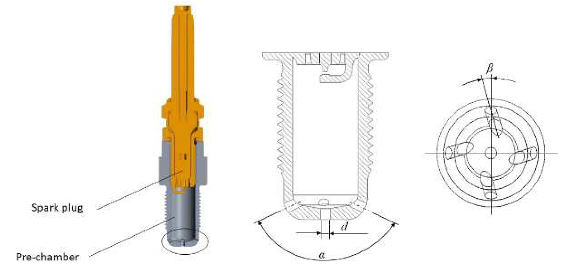
Figure 2.
Computational domain, grid independence verification, and experimental calibration.
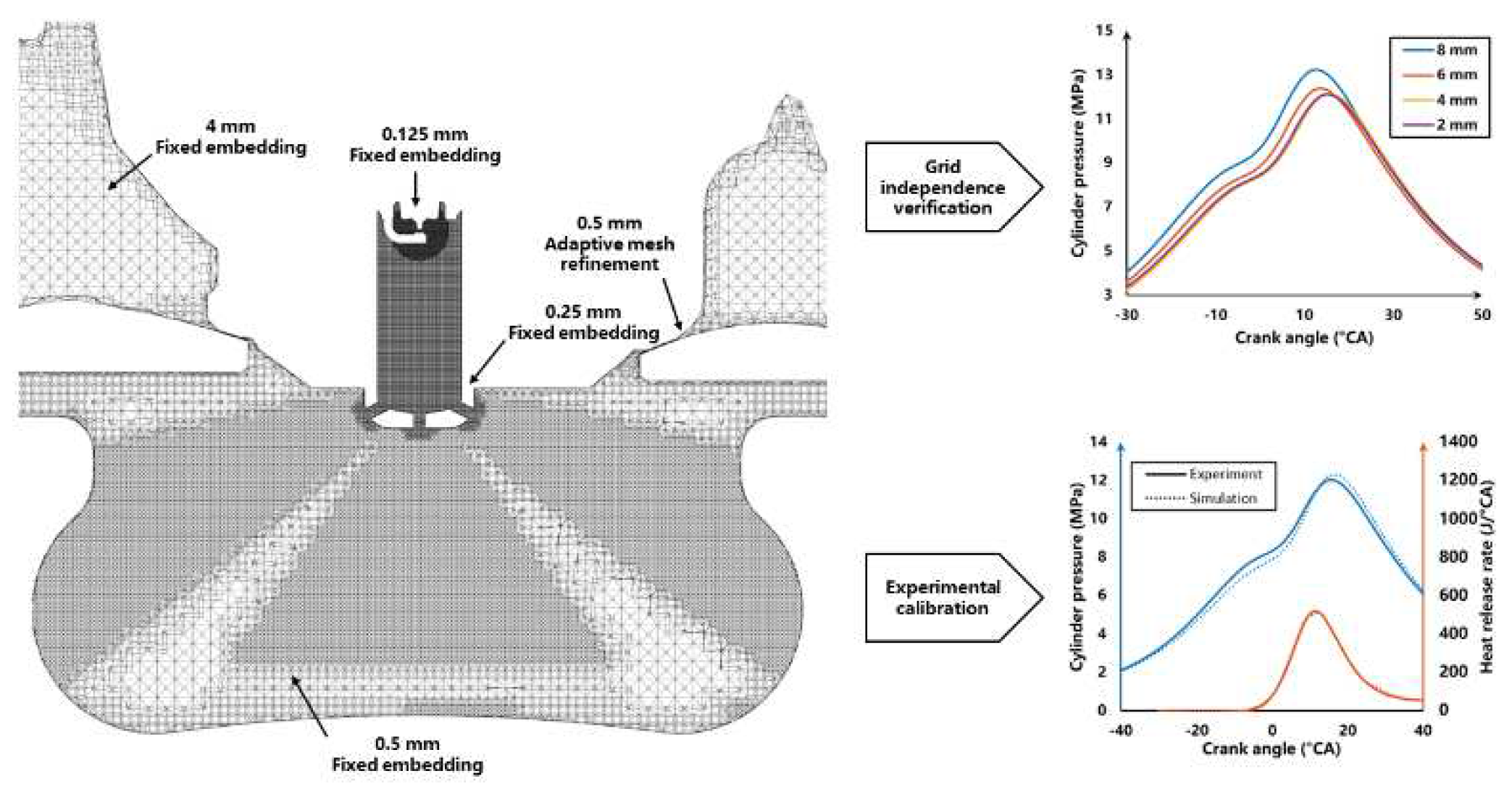
Figure 3.
Velocity contours in pre-camber of 7 caes at -9°CA during scavenging.
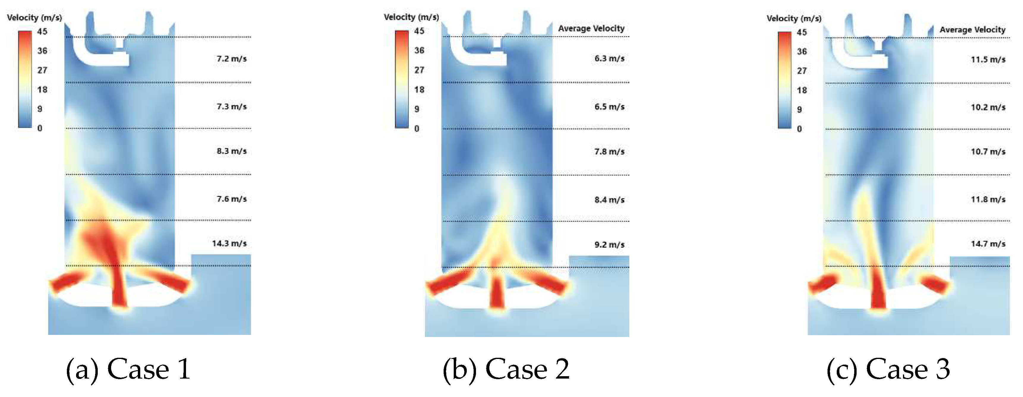
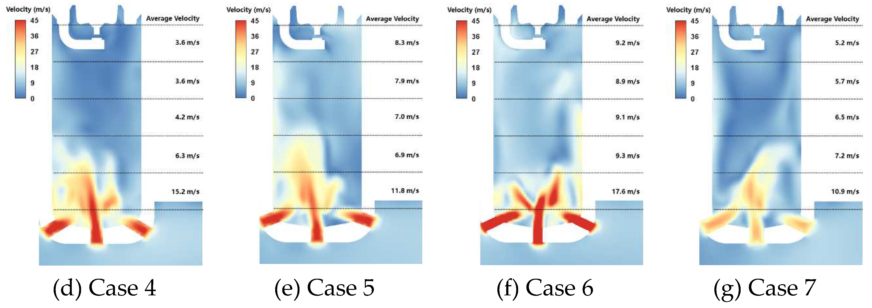
Figure 4.
Residual CO2 mass fraction in pre-chamber of 7 cases at -9°CA during scavenging.
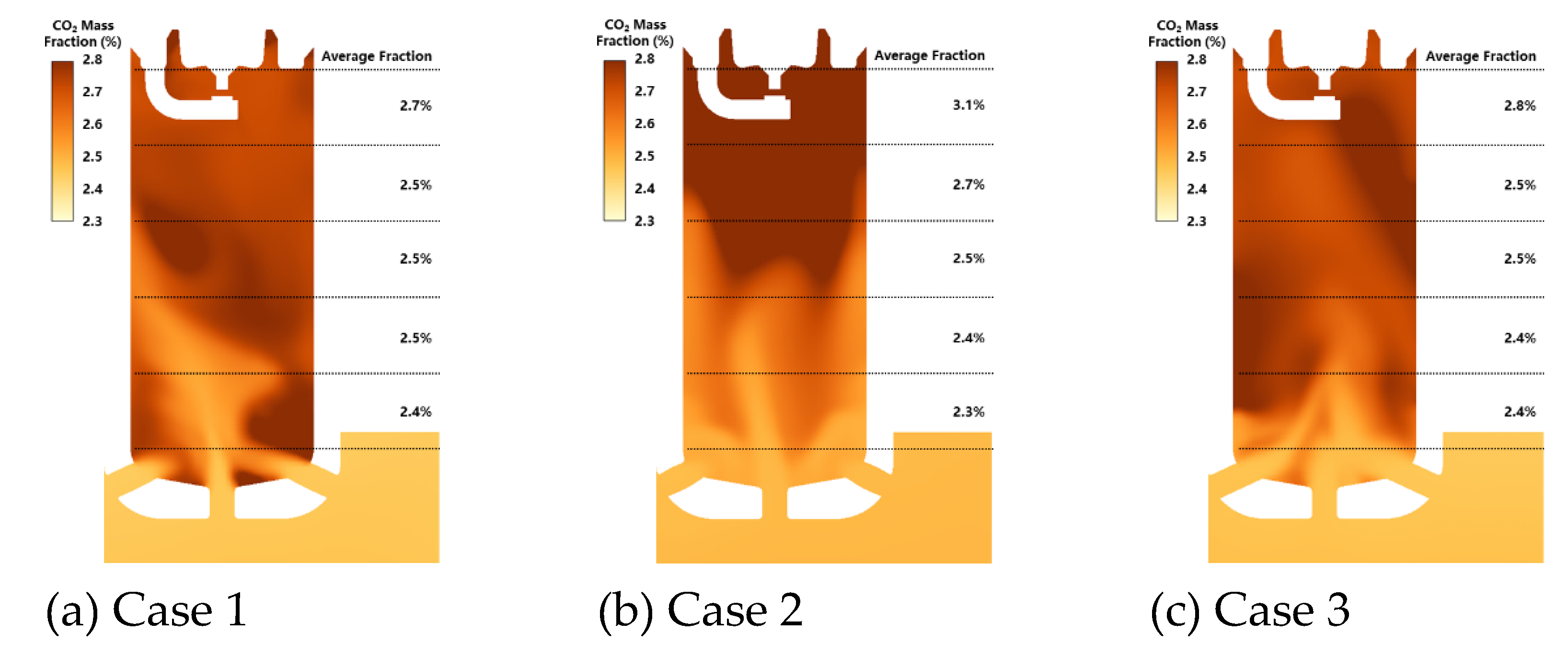
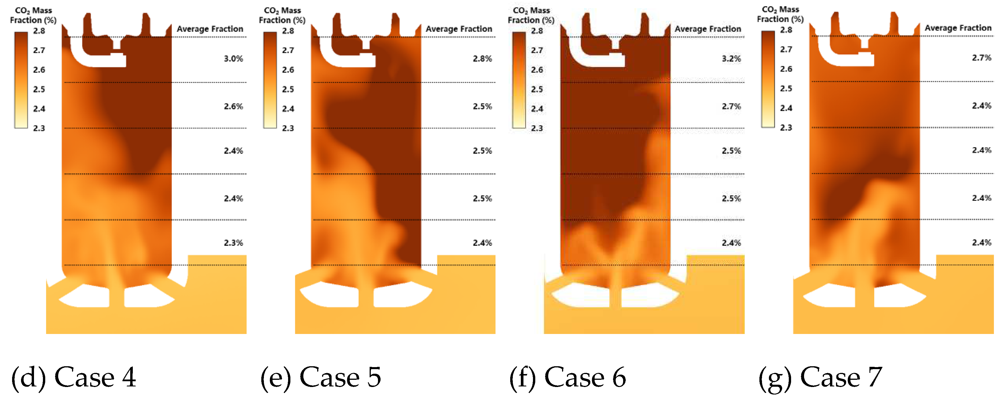
Figure 5.
Turbulent kinetic energy (TKE) in pre-chamber of 7 cases at -9°CA during scavenging.
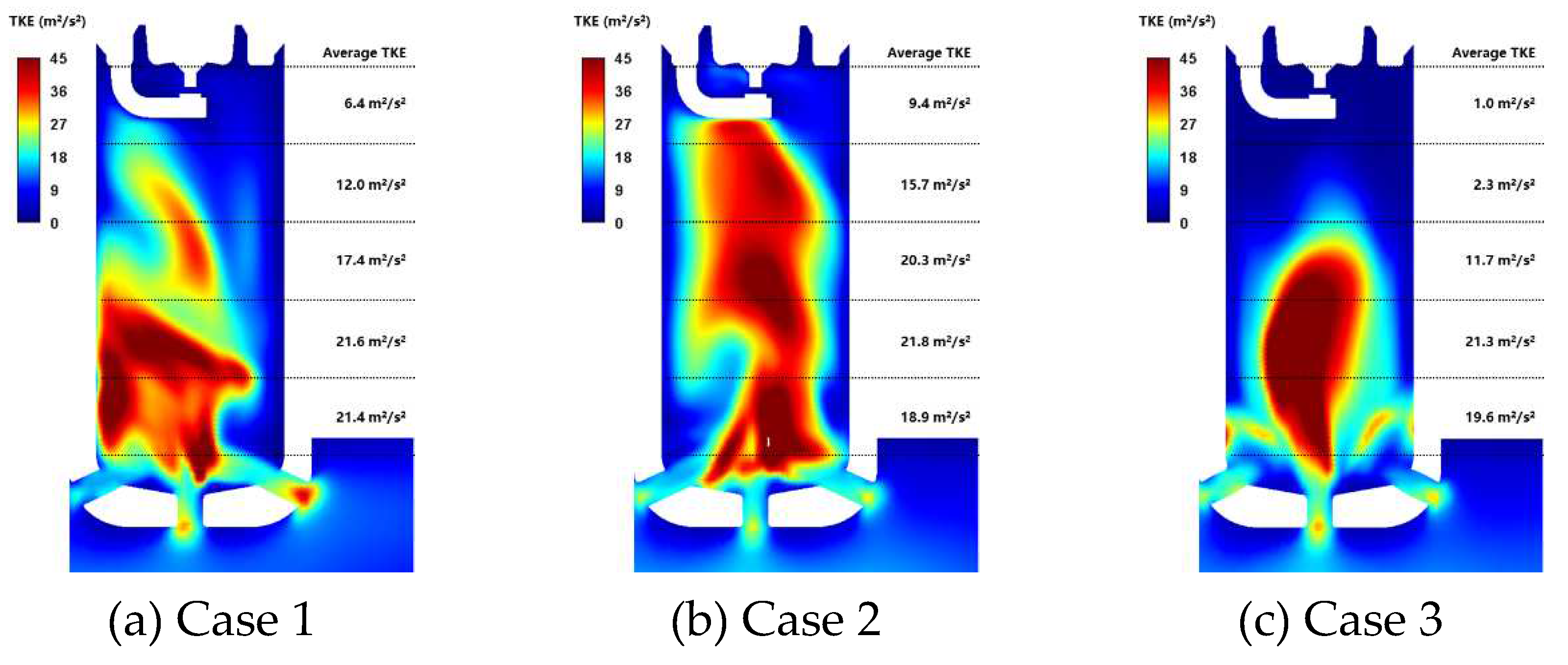
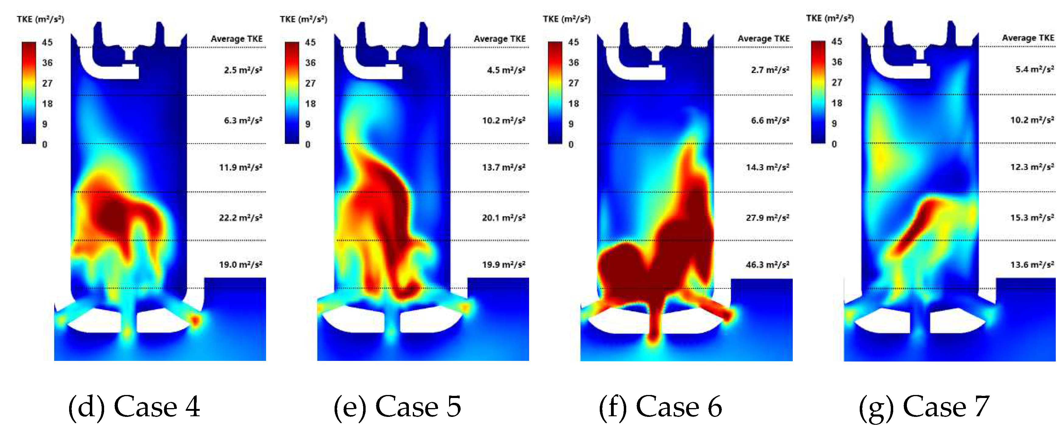
Figure 6.
Flame propagation in the pre-chamber of case 2, case 1, and case 3 during jet ignition.
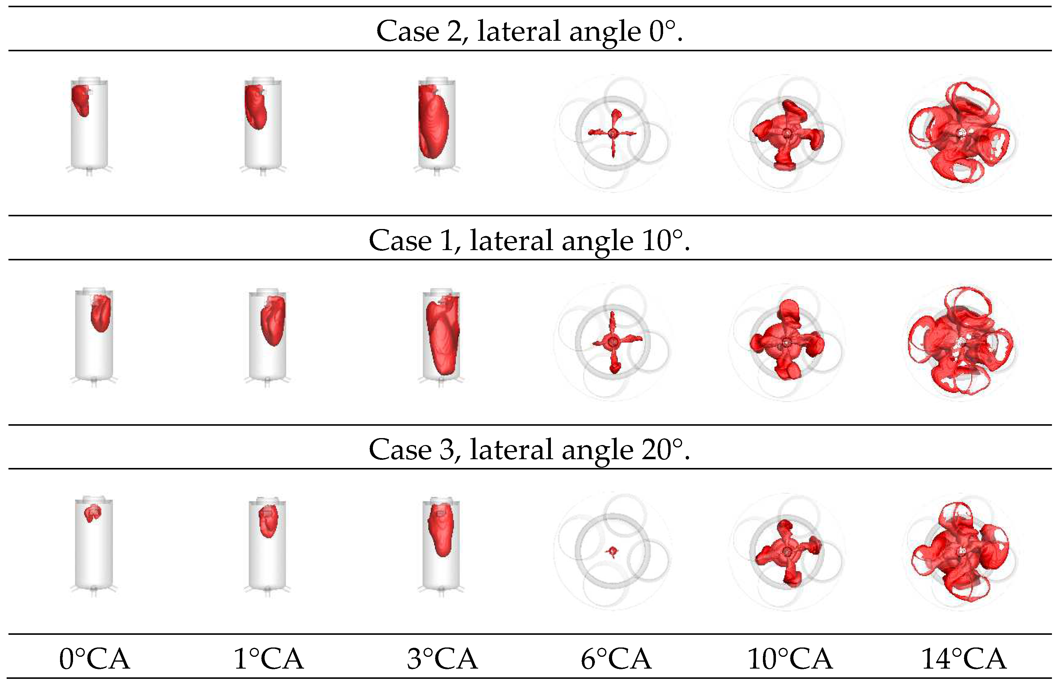
Figure 7.
Flame propagation in the main chamber of case 4, case 1, and case 5 during jet ignition.
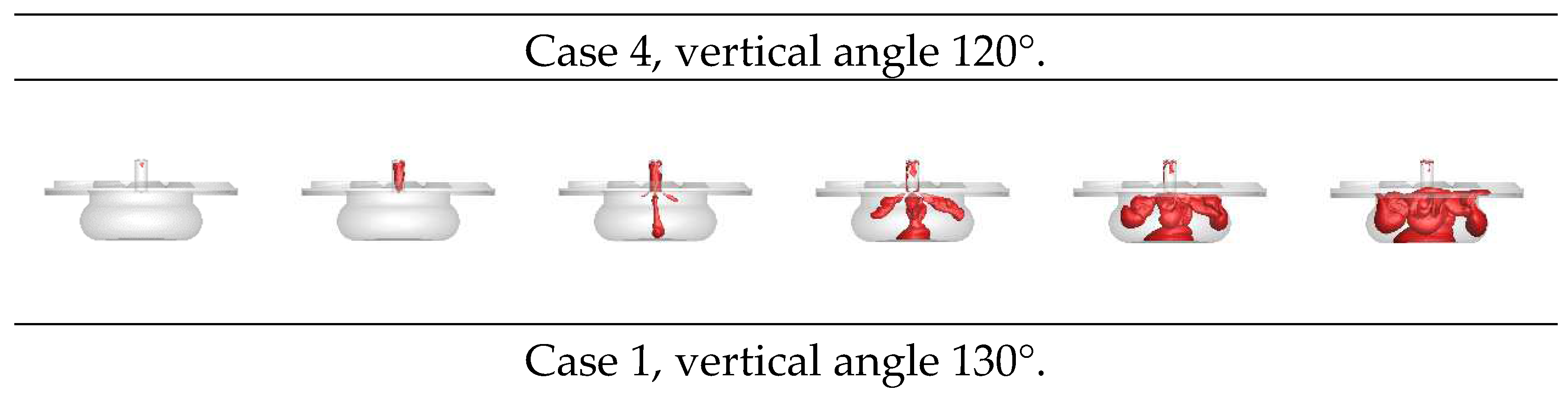
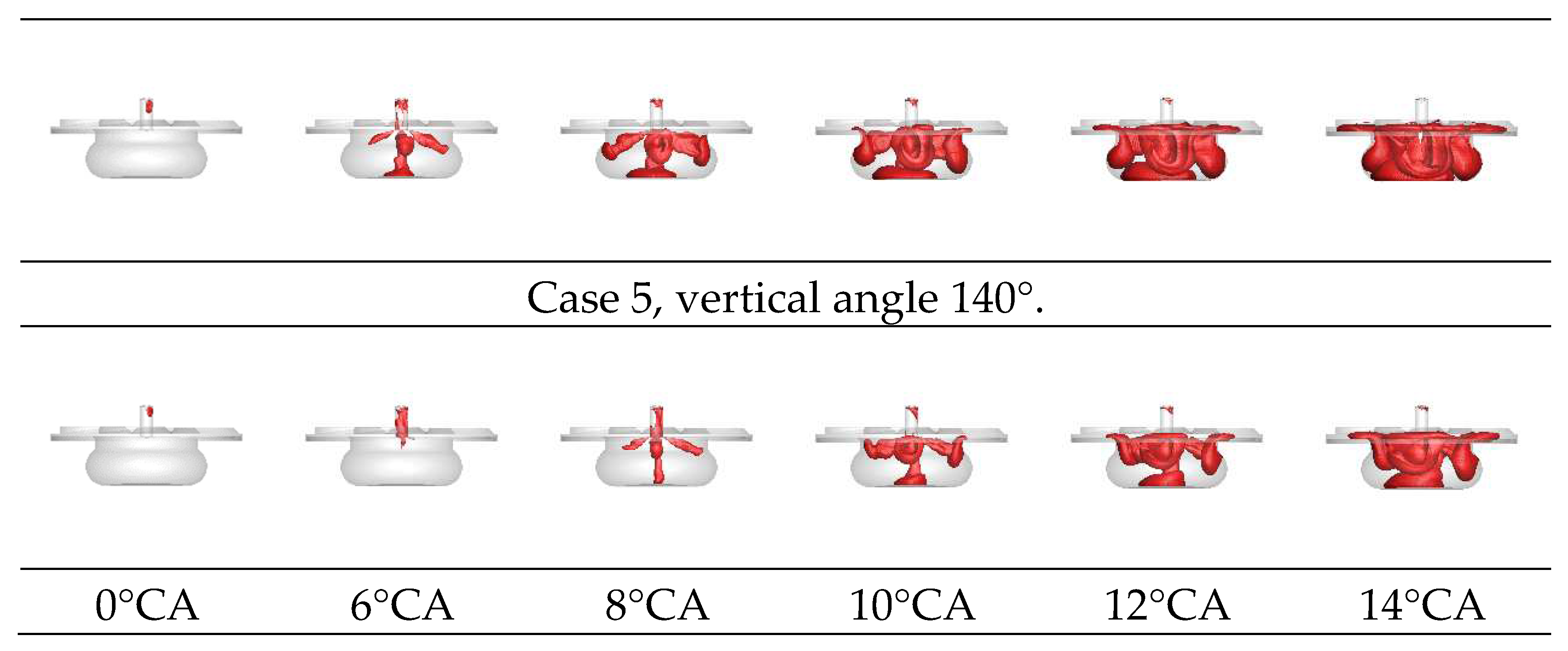
Figure 8.
Flame propagation in the main chamber of case 6, case 1, and case 7 during jet ignition.
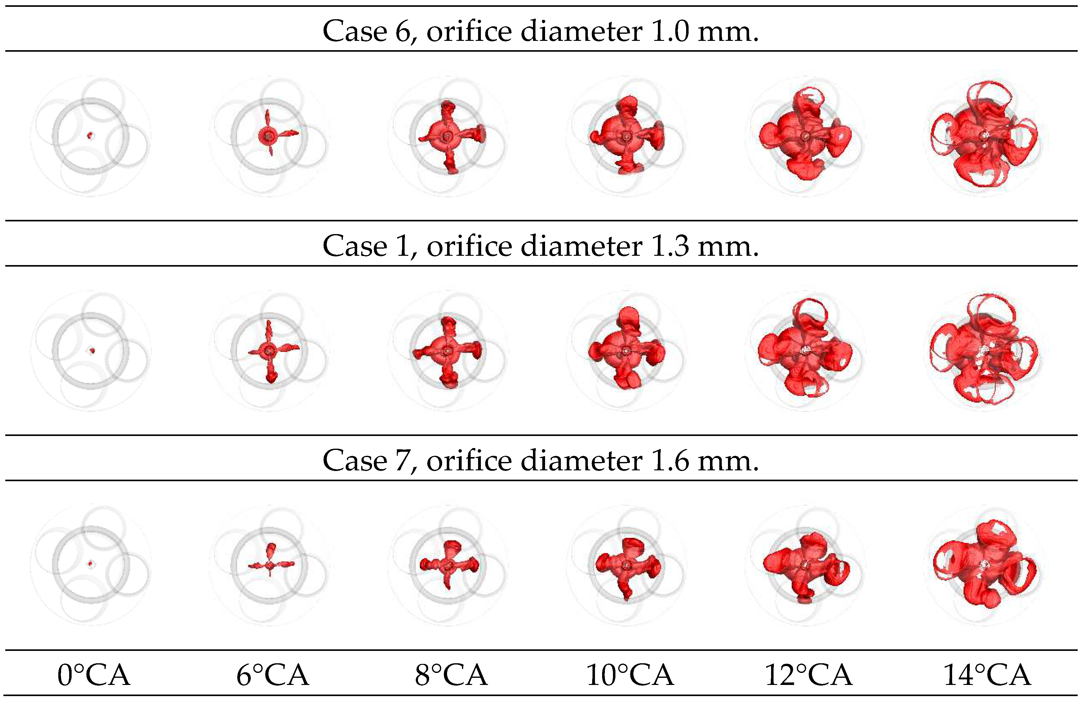
Figure 9.
Mass fractions of cold and hot jets for 7 cases during jet ejection.
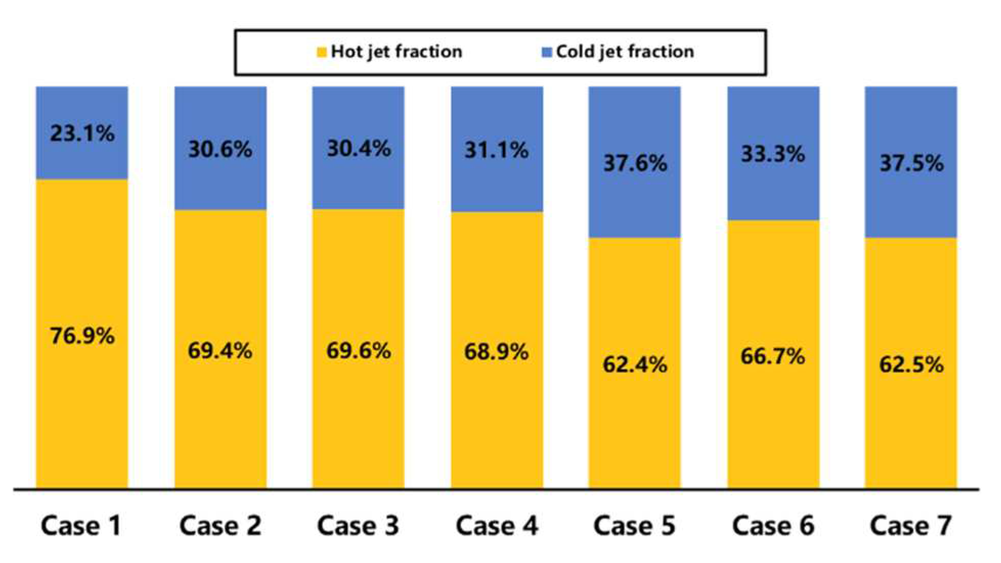
Figure 10.
Cylinder pressure and heat release rate (HHR) of pre-chamber and main chamber for all cases during combustion.
Figure 10.
Cylinder pressure and heat release rate (HHR) of pre-chamber and main chamber for all cases during combustion.
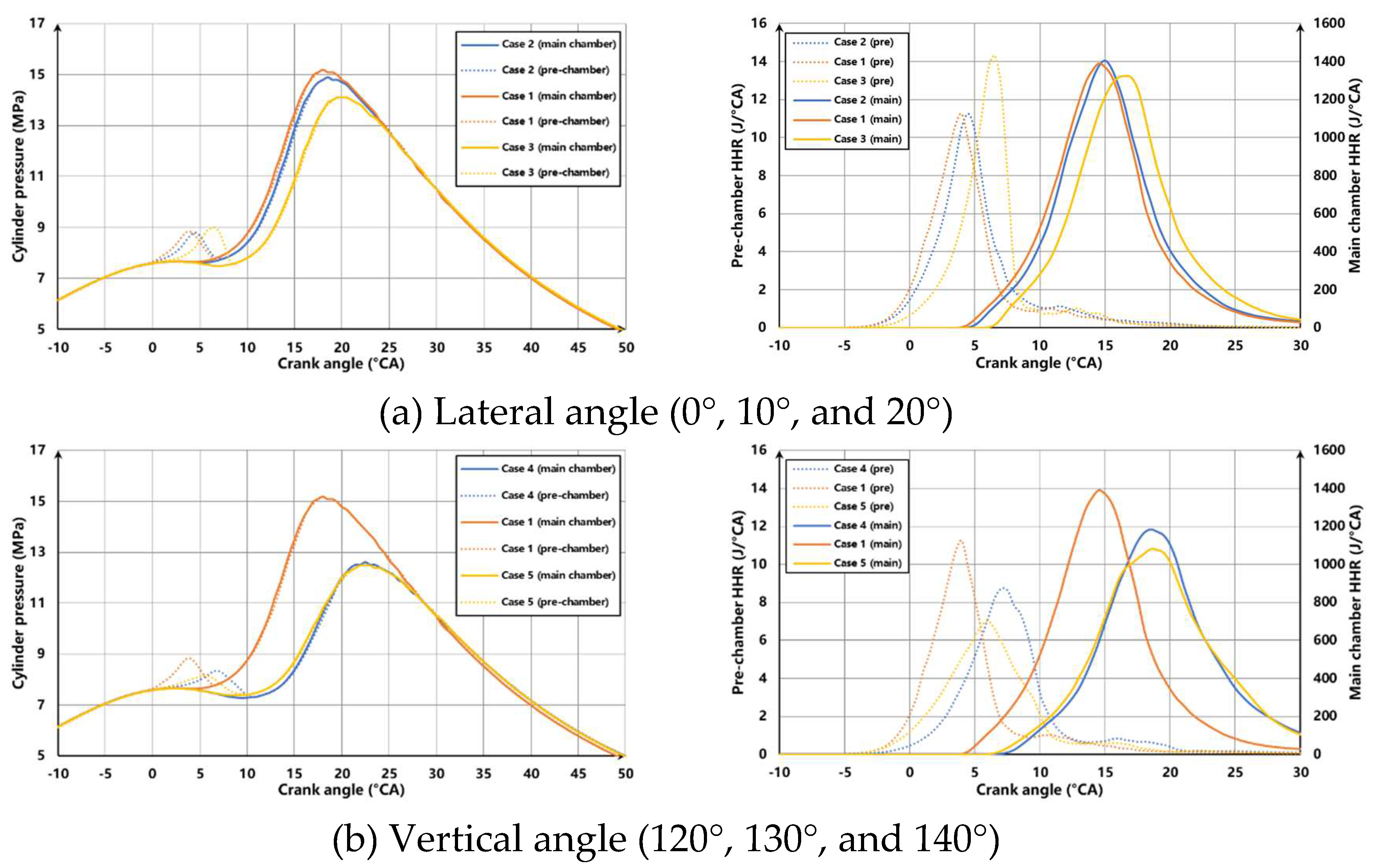
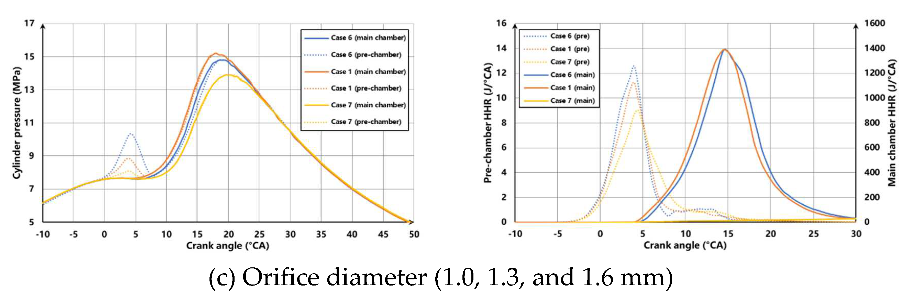
Figure 11.
Experimental data of (a) maximum pressure, (b) knocking frequency, (c) exhaust gas recirculation rate, and (d) fuel consumption of the selected schemes and original engine.
Figure 11.
Experimental data of (a) maximum pressure, (b) knocking frequency, (c) exhaust gas recirculation rate, and (d) fuel consumption of the selected schemes and original engine.
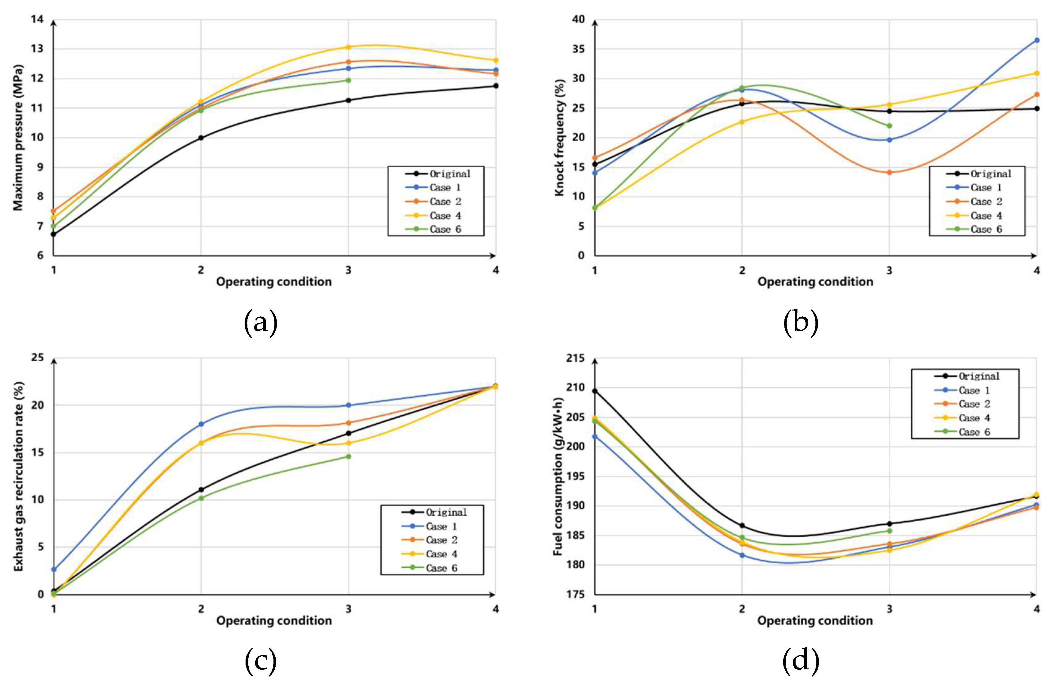

Table 1.
The test cases for passive pre-chamber nozzle research.
| Case | d (mm) | α (°) | β (°) |
| 1 | 1.3 | 130 | 10 |
| 2 | 1.3 | 130 | 0 |
| 3 | 1.3 | 130 | 20 |
| 4 | 1.3 | 120 | 10 |
| 5 | 1.3 | 140 | 10 |
| 6 | 1.0 | 130 | 10 |
| 7 | 1.6 | 130 | 10 |
Table 2.
Table 2. The test engine specifications.
| Item | Value |
| Engine type | In-line six-cylinder, four-stroke |
| Intake system | Turbocharged, intercooler, cooled exhaust gas recirculation |
| Bore | 136 mm |
| Stroke | 167 mm |
| Displacement | 14.6 L |
| Compression ratio | 12.5 |
| Rated power/speed | 390 kW/1700 rpm |
| Maximum torque/speed | 2500 N·m/950~1350 rpm |
Table 3.
Table 3. The bench test operating conditions.
| Case | Speed (r/min) | Torque (N·m) | Conditions |
| 1 | 900 | 1000 | Low speed, low load |
| 2 | 1100 | 2000 | Normal power |
| 3 | 1100 | 2500 | Low speed, high load |
| 4 | 1700 | 2190 | Rated power |
Disclaimer/Publisher’s Note: The statements, opinions and data contained in all publications are solely those of the individual author(s) and contributor(s) and not of MDPI and/or the editor(s). MDPI and/or the editor(s) disclaim responsibility for any injury to people or property resulting from any ideas, methods, instructions or products referred to in the content. |
© 2023 by the authors. Licensee MDPI, Basel, Switzerland. This article is an open access article distributed under the terms and conditions of the Creative Commons Attribution (CC BY) license (http://creativecommons.org/licenses/by/4.0/).
Copyright: This open access article is published under a Creative Commons CC BY 4.0 license, which permit the free download, distribution, and reuse, provided that the author and preprint are cited in any reuse.


