
Submitted:
13 June 2023
Posted:
14 June 2023
You are already at the latest version
Abstract
(1) Background: This article presents a study that aims to provide a precise understanding of the temperature distribution within a Whole-Body Cryostimulation (WBC) chamber, whether it is empty or occupied by one or several individuals.; (2) Methods: The study employs a mixed numerical and experimental approach, utilizing simplified Computational Fluid Dynamics (CFD) simulations and an experimental analysis that employs thermocouples to determine the 3D thermal field in actual conditions.; (3) Results: The results reveal a non-negligible temperature difference between the setpoint and actual temperature in the middle of the cryochamber. Furthermore, it is shown that the presence of individuals inside the chamber results in both an average temperature rise and a more heterogeneous thermal behavior, which appear to be associated with the number of individuals present.; (4) Conclusions: The findings of this study emphasize the need for further research to establish temperature guidelines and standardize measurement methods for effective WBC treatment.
Keywords:
Whole-Body Cryostimulation
; Inside Temperature Fields
; Thermal Stratification
; CFD
1. Introduction
Whole body cryotherapy (WBC) is a technique that entails subjecting one or multiple individuals to extremely cold and dry air within temperature-controlled cryochambers, for a duration ranging from one to four minutes [1]. Extensive research has demonstrated the various physiological, psychological, and physical advantages offered by cryotherapy [2,3,4]. Specifically, cryotherapy techniques have been developed to enhance post-exercise recovery, alleviate pain, and alleviate symptoms of depression and anxiety in patients with rheumatism and inflammatory conditions [5,6,7]. In October 2020, the International Institute of Refrigeration released its 39th Information Note on Refrigeration Technologies [8], which emphasized the need to establish a standardized method for measuring the actual temperatures inside whole-body or partial-body cryotherapy equipment. Furthermore, it is evident that there is a scarcity of well-established protocols and appropriate temperature guidelines to ensure optimal and safe cryotherapy treatments [9]. The scientific literature notably lacks comprehensive data regarding the exact temperature conditions within whole-body cryotherapy chambers, as well as the specific effects of multiple individuals being present during a cryotherapy session. This lack of information underscores the need for further research and investigation to enhance our understanding of these specific aspects. The objective of this study is to investigate the temperature distribution within a cryotherapy chamber as per the practices of cryotherapists. Specifically, the study aims to provide a precise understanding of the temperature distribution within empty chambers when the sole criterion for programming sessions is to reach the machine's set temperature, and whether the actual temperature inside the chamber matches the setpoint temperature. Additionally, the study investigates how the temperature field is affected by the presence of one or several people inside the chamber, which is a common scenario when the chamber size permits.
A mixed numerical and experimental approach is adopted, wherein simplified computational fluid dynamics simulations are used to model the global thermo-aerodynamic behavior inside empty and occupied cryotherapy chambers, and an experimental analysis using a network of thermocouples is conducted to determine the resulting 3D thermal field in real situations and provide answers to the research questions raised. To the best of our knowledge, this is the first study in the literature to investigate this topic in the context of whole-body cryotherapy.
2. Materials and Methods
The equipment utilized in this study was a dual WBC chamber (Mecotec®, 2.10x1.84x2.15 m3) supplied with cold air from a cascade refrigeration system in a closed circuit. The cold air entered the chamber via perforated grids on the ceiling, consisting of 3132 holes of 13 mm diameter, whereas the evacuation occurred from a slotted extraction plate (110 slotted holes 105x20 mm²) located in the lower part of one of the walls with a flow rate of 1500 m3/h. A total of 15 thermocouples (type K 430-2000-2-1) were arranged in the volume, as depicted in Figure 1. and simultaneously connected to a data acquisition system to record local temperature changes. Furthermore, the thermocouples enabled volume mapping restitution through Abaqus® software in conjunction with a finite element interpolation.
To illustrate how the enclosure heats up in the presence of a person, a simplified CFD steady-state model was developed. The walls are considered adiabatic and the dynamic inlet conditions are relative to a cold air flow of 1500 m3/h. The finite volume software ANSYS® 2020 R2 was used, combined with a k-ε turbulence model. The mesh was considered structured, varying from 0.6x10⁶ cells (empty chamber) to 2.4x10⁶ cells (one male inside). A male 3D body (Artec® scanner) was used and initialized at a constant surface temperature of 27°C corresponding to the mean value of male skin temperature during a WBC session [10,11].
Regarding the influence of persons considered as volume heated sources within the actual chamber, three young healthy participants (two females and one male), staff members of a cryocenter participated in this study. Corresponding anthropometric data are given in Table 1.
Body Surface Area and Body Volume were derived from the empirical formulas of Schumm et al. [12] and Sendroy & Collison [13] respectively. Moreover, the dissipated heat power per person was estimated at ambient temperature based on the energy balance equations [14]. Figure 1 illustrates the general positioning of the the individuals within the cryotherapy chamber. They are situated in the center of the chamber walls, approximately 30 cm away from the edges.
3. Results
3.1. Setpoint temperature vs actual temperature
The temperature mentioned (setpoint temperature) often refers to the temperature of the air at the outlet or in the vicinity of the expansion device. Unlike in cryosaunas (Partial Body Cryotherapy), where studies have demonstrated significant differences between the actual temperature inside the cryocabin and the temperatures reported by manufacturers [15,16], no research has been conducted on this topic for Whole Body Cryotherapy. To answer the question regarding the agreement between the setpoint temperature and the actual temperature in the middle of the cryochamber in WBC, Figure 2 presents the time evolution of both these fields. We began recording the two temperatures (setpoint and actual) when the setpoint temperature reached -94°C. It is evidenced that there is a strong temperature difference between the two curves over time. Once the steady state was reached, the difference was 18°C, corresponding to a 16% increase compared to the setpoint temperature. The main reason lies in the very high thermal gradient between the inside and the outside of the chamber, yielding thermal gains from walls, door, floor, and window as well as from thermal bridges at the mechanical junctions between walls and upper/ground floors. Although this study focuses on a specific technology, it can be assumed that other technologies face similar challenges.
3.2. Experimental 3D temperature fields
The experimental approach proved to be challenging to implement within the chamber due to the extreme temperatures and thermal limitations present, which render current electronic measurement devices incompatible. Consequently, we had to restrict our measurements to an actual temperature of -80°C. Figure 3 displays the temperature distribution inside the cryochamber over time for three scenarios, with and without participants, at various timestamps during a typical cryotherapy session of 3 min. The empty prisms in columns b and c indicate the approximate position of each participant. The results indicate that the presence of multiple occupants has a significant impact on the thermal fields inside the cryochamber. It should be noted that the hot thermal convective plumes are shifted towards the outlet, which is located at the bottom of the backside. This approach of accommodating several individuals together inside the cryochamber, driven by economic considerations, must be carefully considered in terms of response/dose balance. In other words, the duration of the protocol should be increased proportionally to the number of occupants present.
To better analyze the temperature distribution inside the chamber, two parameters have been introduced: the thermal gradient and the thermal heterogeneity percentage The thermal gradient is defined as the difference between the maximum and minimum temperatures recorded inside the chamber, expressed as:
On the other hand, the thermal heterogeneity percentage is defined as the absolute value of the ratio between the thermal gradient inside the whole studied volume and the minimum temperature. Specifically:
A completely homogeneous temperature field inside the chamber, where the maximum and minimum temperatures are equal, corresponds to , while indicates that the maximum temperature is zero. The time-evolutions of the thermal gradient ΔT and thermal heterogeneity percentage are presented in Figure 4. It can be observed that an empty chamber exhibits a homogeneous thermal situation with limited stratification. However, as the number of occupants in the cryochamber increases, the magnitude of the thermal gradient (up to 10°C) and temperature heterogeneity (up to 13%) also increase. The observation of a stable thermal behavior with three participants, compared to a single participant where the two analyzed parameters increase over time, may be attributed to a more uniform spatial distribution of human heat sources within the volume.
4. Qualitative evidence of numerical thermo-aeraulic fields
4.1. Computational grid
The size of the mesh elements was meticulously determined, taking into account the criteria obtained from a comprehensive grid convergence study, which is extensively described in a recent article [17]. Firstly, a surface mesh is generated on the body, which is then followed by the creation of a Cartesian volumetric mesh for the fluid domain. In the computational domain, the cell size is set to be smaller than or equal to 0.023 m. The cell size assigned to the body ensures a high level of resolution for the boundary layer and ensures sufficient accuracy for thermal transfer and convection calculations within the air. The utilization of a structured Cartesian mesh contributes to improved convergence of results and helps to restrict the number of mesh cells. Overall, the mesh encompasses more than 3.5 million cells. To visually depict this, Figure 5 showcases the mesh structure on the body walls and in its immediate vicinity.
4.2. Numerical methods
In this investigation, the commercially available computational fluid dynamics (CFD) software ANSYS Fluent® 2020 R2 was employed. This CFD solver, which utilizes the finite volume method, facilitates the solution of the governing equations for fluid flow. The numerical study conducted was three-dimensional, time-dependent, and non-isothermal in nature. For the resolution of pressure-velocity coupling, the widely used SIMPLE algorithm was employed, employing a first-order discretization scheme [18]. To model turbulence effects, the standard k-ε turbulence model was selected, which serves as a closure for the Reynolds-averaged Navier-Stokes equations. Heat transfer and convective mass transfer were represented using the following equations:
The continuity equation:
The Navier-Stokes equations:
The energy equation:
With being the fluid velocity (m/s); the dynamic viscosity (kg/m.s); ,, the spatial coordinates (m); the Pressure (Pa); the density (kg/m3); the temperature (K); the specific heat (J/Kg.K); the thermal conductivity (W/m/K).
Polynomial laws were incorporated into the computational code to accurately capture the variations in thermo-physical properties of air with temperature. These laws enable the calculation of density, dynamic viscosity, thermal conductivity, and specific heat at each time step within the temperature range of -110°C to 33°C, which encompasses the relevant temperature range of interest.
The numerical injected temperature was -80°C, corresponding to the range later chosen to avoid experimental equipment failure due to extreme cold. Modeling the empty chamber using simplified adiabatic wall conditions reveals a 3D primary curvilinear flow stream from inlet to outlet, associated with a large-scale primary vortex cell and secondary spiral-type vortices at the top and side edges (see Figure 6). To evidence both flow patterns and convective effects, the CFD results illustrate how heat released by a person (mean skin temperature 27°C) situated in the center of the room is transported to the exhaust vents. The resulting 3D complex convective flow results in local temperature heterogeneities, maybe leading to both thermal stratification and non-whole-mixing process which are experimentally to be verified.
Figure 7 depicts the temperature fields associated with three subjects in the CCE chamber at t=180 s. Notably, the man's temperature is observed to be higher compared to the two women. When comparing the two women, it can be observed that the woman positioned near the aeraulic outlet experiences a more pronounced cooling effect than the woman in the middle. By examining both Figure 6 and Figure 7, it becomes evident that the flow topology plays a crucial role in influencing the cooling process of the female subject situated on the left side of the Figure. This is attributed to the acceleration of air velocity at the outlet, which enhances heat exchange and subsequently promotes skin cooling, particularly in the lower extremities.
Figure 8 presents a comparison of the time-dependent evolution of average skin temperature for a single individual during a 180-second continuous cooling exposure (CCE) session. The experimental data is contrasted with the numerical simulation, highlighting the numerical method's capability to accurately replicate the heat transfer processes between the human body and its surrounding environment. These findings underscore the reliability and validity of the numerical approach in studying thermal dynamics in human subjects.
5. Conclusions
The present pilot study reveals two major points. Firstly, it appears necessary for a reflection to be initiated among the community of cryogenic chamber users (manufacturers, physicians, cryotherapists, researchers) regarding the concordance between set temperatures and the temperatures actually reached in the chamber volume. Secondly, the common practice of having multiple people in the chamber simultaneously requires an awareness of the induced thermal modifications, leading to an appropriate adaptation of protocol duration, particularly when the analgesic thermal threshold is the targeted value of cutaneous temperatures. The results showed, for example, that an empty chamber exhibits a homogeneous thermal situation with limited stratification, whereas as the number of occupants in the cryochamber increases, the magnitude of the thermal gradient (up to 10°C) and temperature heterogeneity (up to 13%) also increase. Future studies should target this current topic.
Author Contributions
Conceptualization, R.E. and F.BE.; methodology, G.P.; software, R.E.; validation, F.BO.; G.P. and B.A.; formal analysis, B.B.; investigation, R.E.; resources, B.B.; data curation, B.B.; writing—original draft preparation, G.P.; writing—review and editing, F.BE. and F.BO.; visualization, T.M.; supervision, S.M. All authors have read and agreed to the published version of the manuscript.
Funding
This research received no external funding.
Data Availability Statement
Data are available on request to first author.
Conflicts of Interest
The authors declare no conflict of interest.
References
- Polidori, G.; Taiar, R.; Legrand, F.; Beaumont, F.; Murer, S.; Bogard, F.; Boyer, F.C. Infrared thermography for assessing skin temperature differences between Partial Body Cryotherapy and Whole Body Cryotherapy devices at −140 °C. Infrared Physics & Technology 2018, 93, 158–161. [Google Scholar] [CrossRef]
- Hausswirth, C.; Schaal, K.; Le Meur, Y.; Bieuzen, F.; Filliard, J.-R.; Volondat, M.; Louis, J. Parasympathetic activity and blood catecholamine responses following a single partial-body cryostimulation and a whole-body cry-ostimulation. PLoS ONE 2013, 8, e72658. [Google Scholar] [CrossRef] [PubMed]
- Banfi, G.; Melegati, G.; Barassi, A.; Dogliotti, G.; Melzi d’Eril, G.; Dugué, B.; Corsi, M.M. Effects of whole-body cryo-therapy on serum mediators of inflammation and serum muscle enzymes in athletes. Journal of Thermal Biology 2009, 34, 55–59. [Google Scholar] [CrossRef]
- Straburzyńska-Lupa, A.; Kasprzak, M.P.; Romanowski, M.W.; Kwaśniewska, A.; Romanowski, W.; Iskra, M.; Rutkowski, R. The Effect of Whole-Body Cryotherapy at Different Temperatures on Proinflammatory Cy-tokines, Ox-idative Stress Parameters, and Disease Activity in Patients with Ankylosing Spondylitis. Oxid Med Cell Longev 2018, 2018, 2157496. [Google Scholar] [CrossRef] [PubMed]
- Algafly, A.A.; George, K.P. The effect of cryotherapy on nerve conduction velocity, pain threshold and pain tolerance. British Journal of Sports Medicine 2007, 41, 365–369. [Google Scholar] [CrossRef] [PubMed]
- Rymaszewska, J.; Ramsey, D.; Chładzińska-Kiejna, S. Whole-body cryotherapy as adjunct treatment of depressive and anxiety disorders. Arch Immunol Ther Exp (Warsz) 2008, 56, 63–68. [Google Scholar] [CrossRef] [PubMed]
- Vitenet, M.; Tubez, F.; Marreiro, A.; Polidori, G.; Taiar, R.; Legrand, F.; Boyer, F.C. Effect of whole body cryotherapy interventions on health-related quality of life in fibromyalgia patients: A randomized controlled trial. Complement Ther Med 2018, 36, 6–8. [Google Scholar] [CrossRef] [PubMed]
- Dugue, B.; Bernard, J.P.; Bouzigon, R.; de Nardi, F.; Douzi, W.; Feirreira, J.J.; Guilpart, J.; Lombardi, G.; Miller, E.; Tiemessen, I. WHOLE BODY CRYOTHERAPY / “The use of cryostimulation is growing exponentially. However, solid scientific evidence of its benefits remains to be provided.” 39th Informatory Note on Refrigeration Technologies, International Institute Of Refrigeration; october 2020.
- Coulomb, D. La cryothérapie du corps entier: Pour une meilleure approche scientifique. International Journal of Refrigeration 2017, 78, v–vi. [Google Scholar]
- Cuttell, S.; Hammond, L.; Langdon, D.; Costello, J. Individualising the exposure of −110 °C whole body cryotherapy: The ef-fects of sex and body composition. Journal of Thermal Biology 2017, 65, 41–47. [Google Scholar] [CrossRef] [PubMed]
- Polidori, G.; Elfahem, R.; Abbes, B.; Bogard, F.; Legrand, F.; Bouchet, B.; Beaumont, F. Preliminary study on the effect of sex on skin cooling response during whole body cryostimulation (−110 °C): Modeling and prediction of exposure durations. Cryobiology 2020, 97, 12–19. [Google Scholar] [CrossRef] [PubMed]
- Schumm, M.; Schlich, M.; Schlich, E. 3D-body-scan als Anthropometrisches Verfahren zur Bestimmung der Spezifischen Körperoberfläche. Ernahrungs Umschau 2010, 57, 178–183. [Google Scholar]
- Sendroy, J.; Collison, H.A. Determination of human body volume from height and weight. Journal of Applied Physiology 1966, 21, 167–172. [Google Scholar] [CrossRef] [PubMed]
- Polidori, G.; Cuttell, S.; Hammond, L.; Langdon, D.; Legrand, F.; Taiar, R.; Boyer, F.C.; Costello, J.T. Should whole body cryo-therapy sessions be differentiated between women and men? A preliminary study on the role of the body thermal resistance. Medical Hypotheses 2018, 120, 60–64. [Google Scholar] [CrossRef] [PubMed]
- Beaumont, F.; Bogard, F.; Murer, S.; Langlois, A.; Polidori, G. Thermodynamic Correlation between Actual Temperature and Cryogenic Flow Rate in an Empty Cryosauna. Heat Transfer Engineering 2022, 43, 1743–1754. [Google Scholar] [CrossRef]
- Savic, M.; Fonda, B.; Sarabon, N. Actual temperature during and thermal response after whole-body cryotherapy in cryo-cabin. Journal of Thermal Biology 2013, 38, 186–191. [Google Scholar] [CrossRef]
- Elfahem, R.; Bouchet, B.; Abbes, B.; Polidori, G.; Beaumont, F. Influence of Body Heat Loss on Temperature and Velocity Fields in a Whole-Body Cryotherapy Chamber. Preprints.org 2023, 2023051249. [Google Scholar] [CrossRef]
- Beaumont, F.; Bogard, F.; Hakim, H.; Murer, S.; Bouchet, B.; Polidori, G. Modeling of an Innovative Nitrogen-Free Cryotherapy Device. Dynamics 2021, 1, 204–216. [Google Scholar] [CrossRef]
Figure 1.
Experimental WBC chamber: (a) empty; (b) with one person inside; (c) with three persons. The experimental thermal inner volume is represented in red dashed lines.
Figure 1.
Experimental WBC chamber: (a) empty; (b) with one person inside; (c) with three persons. The experimental thermal inner volume is represented in red dashed lines.
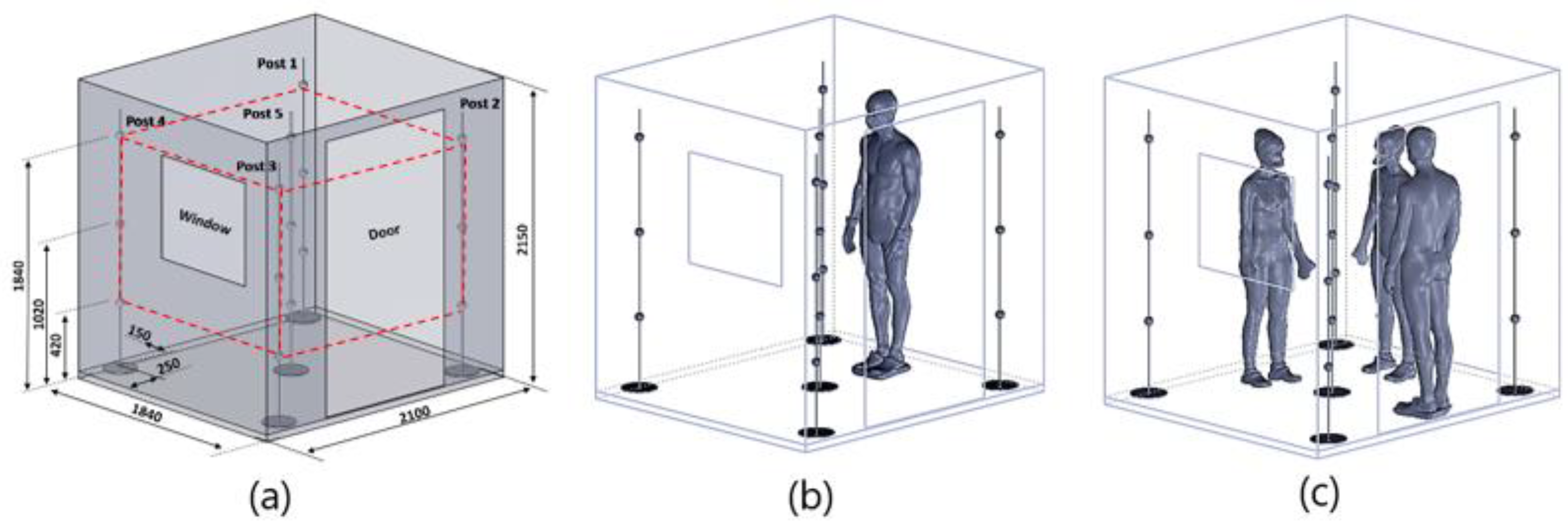
Figure 2.
Comparison of time evolution between setpoint and actual temperatures.
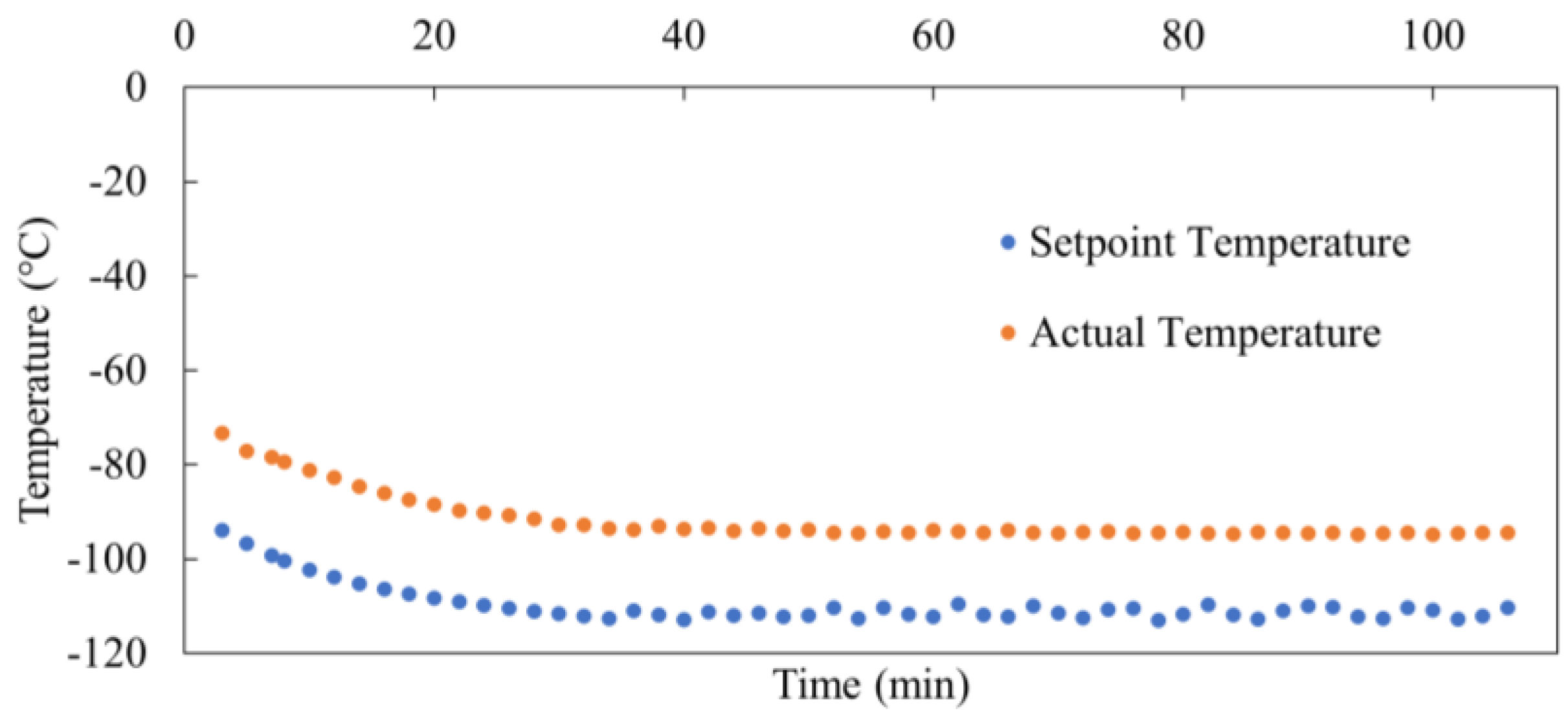
Figure 3.
Time evolution of 3D temperature fields inside the measurement volume: (column a) empty chamber, (column b) chamber with one person, (column c) chamber with three persons.
Figure 3.
Time evolution of 3D temperature fields inside the measurement volume: (column a) empty chamber, (column b) chamber with one person, (column c) chamber with three persons.
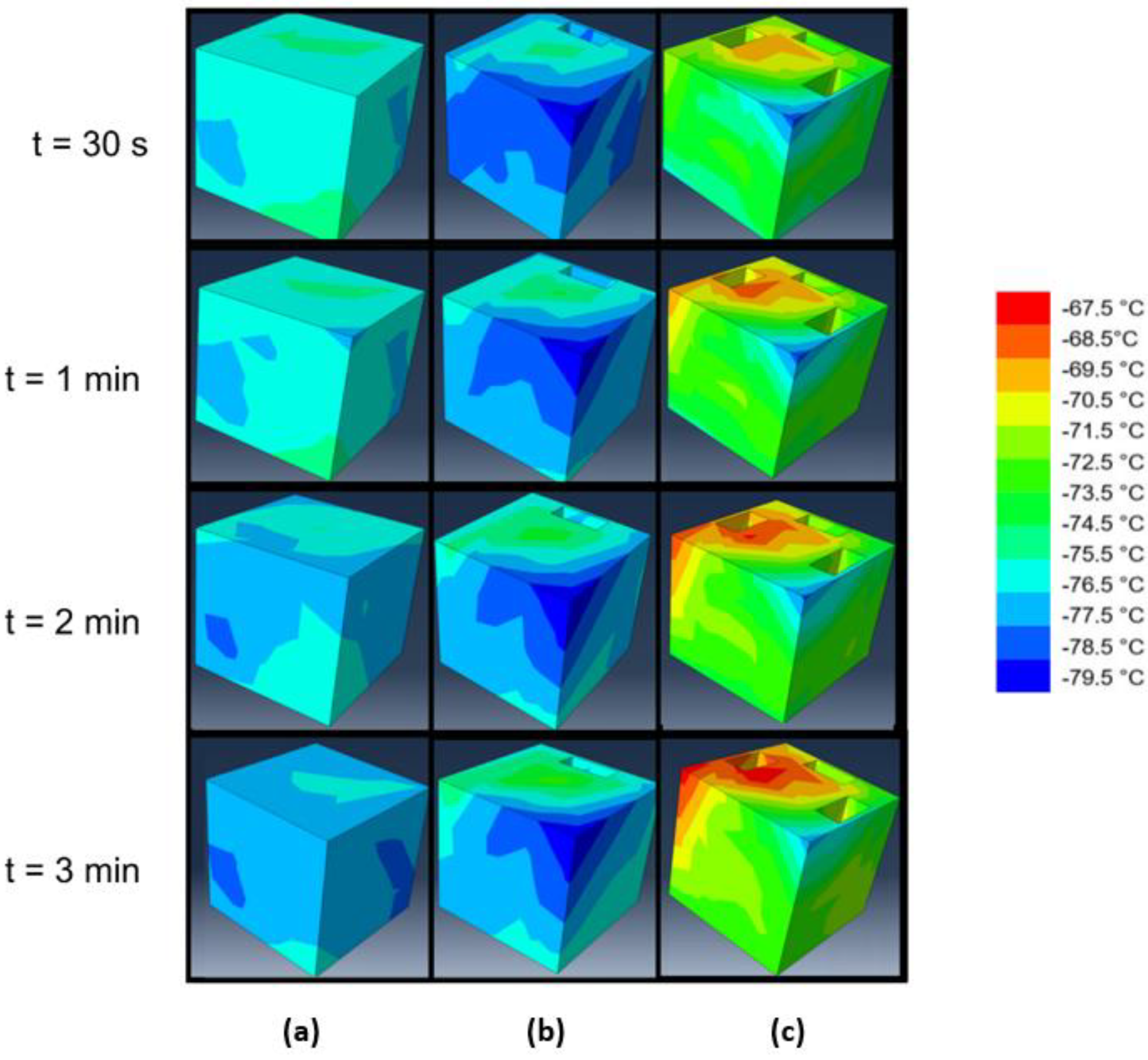
Figure 4.
Temperature magnitude (ΔT) and thermal heterogeneity (TH) percentage vs time.
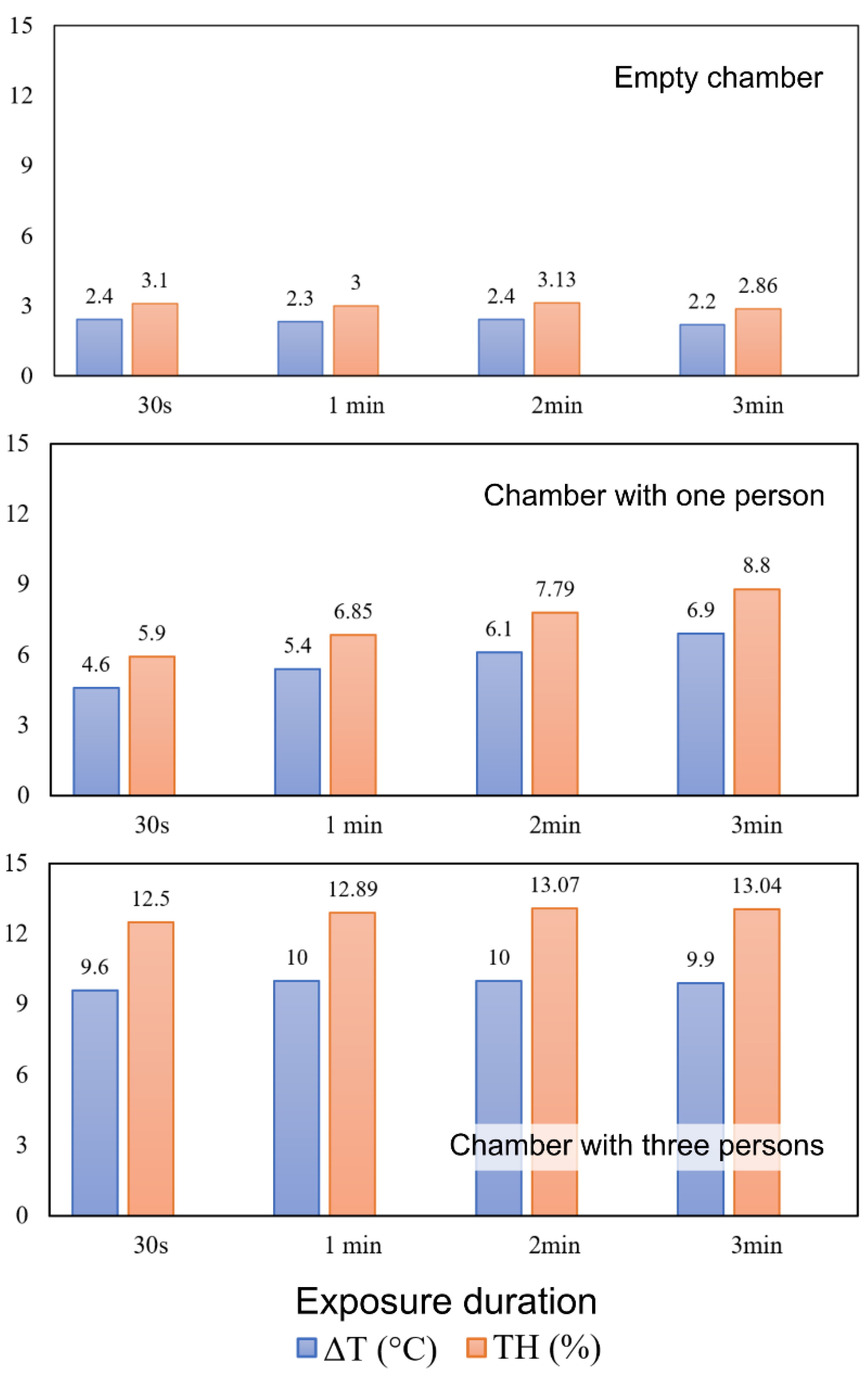
Figure 5.
Surface mesh on the body for male (a) and female (b); detailed view of the inflation mesh around the bodies displayed in a 2D sagittal plane.
Figure 5.
Surface mesh on the body for male (a) and female (b); detailed view of the inflation mesh around the bodies displayed in a 2D sagittal plane.
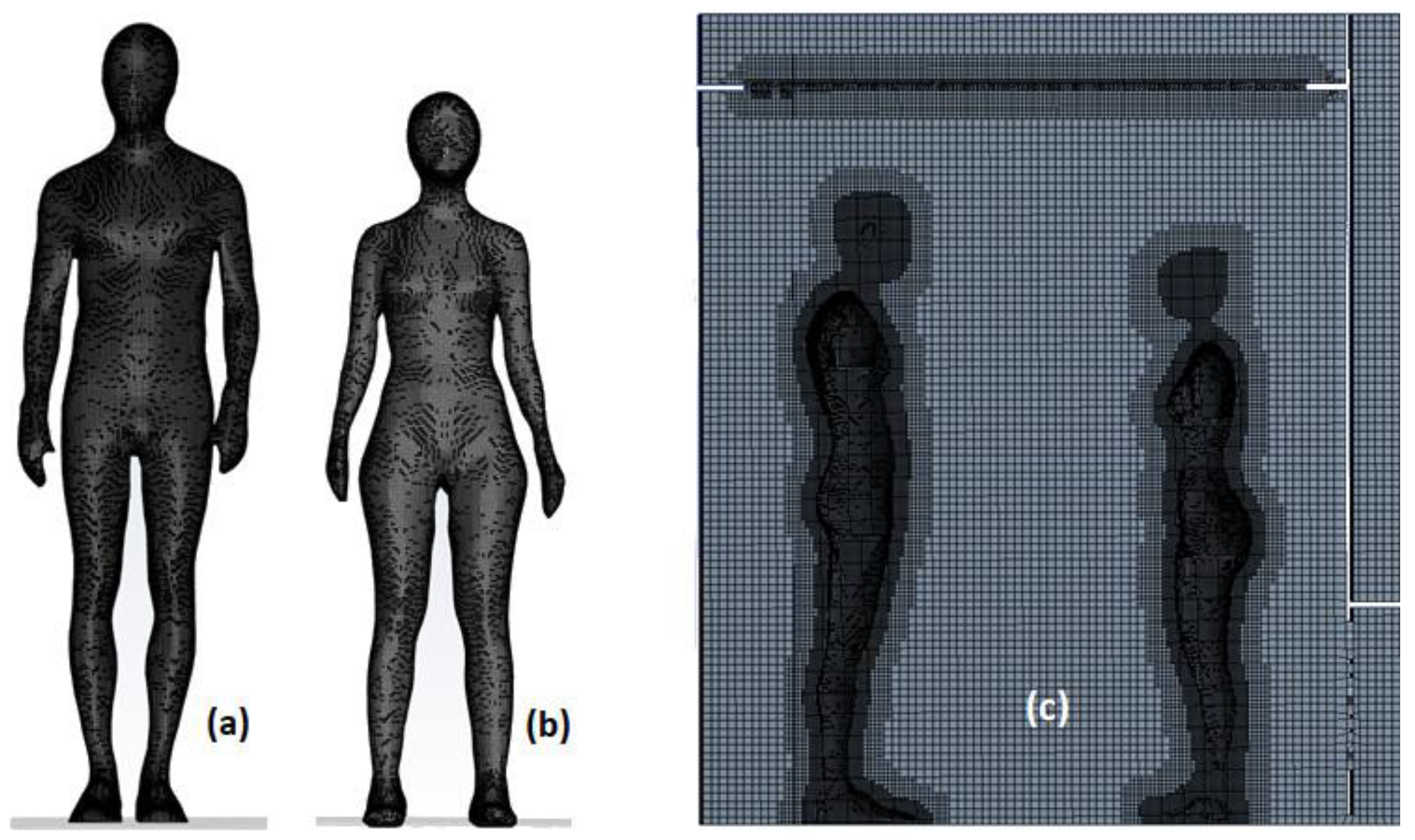
Figure 6.
Temperature color-coded 3D streamlines: (a) empty chamber; (b) chamber with one person inside; chamber with 3 persons inside (c). Inlet temperature -80°C; average body skin temperature 27°C.
Figure 6.
Temperature color-coded 3D streamlines: (a) empty chamber; (b) chamber with one person inside; chamber with 3 persons inside (c). Inlet temperature -80°C; average body skin temperature 27°C.

Figure 7.
Distribution of body surface temperatures for the three subjects at t= 180 s.
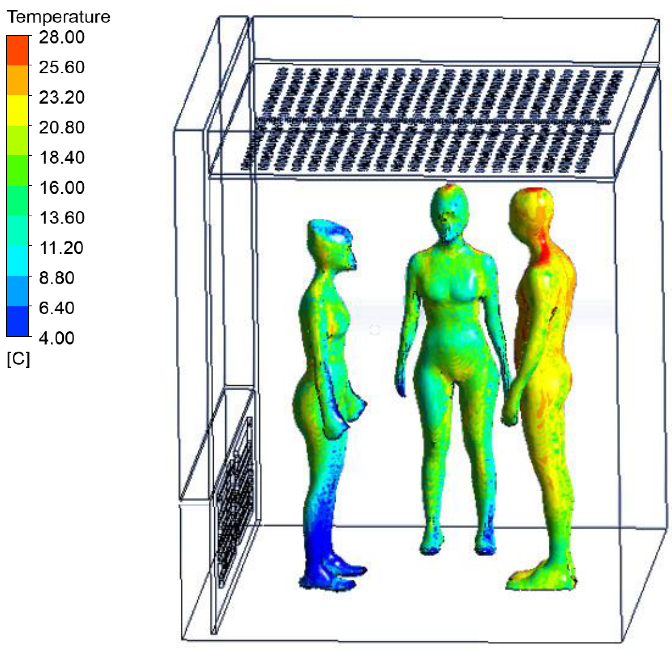
Figure 8.
Temporal evolution of the mean skin temperature of the single male during a 180-second continuous cooling exposure (CCE) session using experimental (EXP) and numerical methods (CFD).
Figure 8.
Temporal evolution of the mean skin temperature of the single male during a 180-second continuous cooling exposure (CCE) session using experimental (EXP) and numerical methods (CFD).
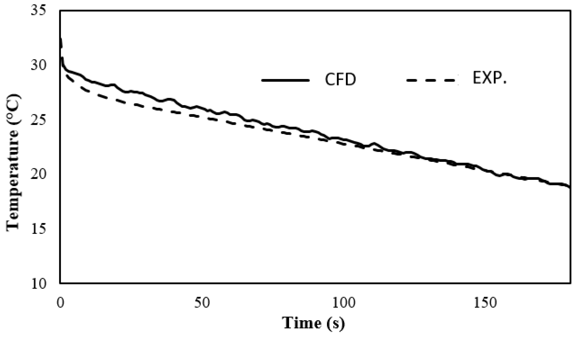

Table 1.
Anthropometric data of study participants (BMI: Body Mass Index; BSA: Body Surface Area).
| Subjects | Height (cm) | Weight (kg) | BMI (kg/m2) | BSA (m2) | Volume (m3) | Dissipated heat power (W) |
|---|---|---|---|---|---|---|
| Male 1 | 187 | 82 | 23.4 | 2.02 | 0.07651 | 202.2 |
| Female 1 | 165 | 54 | 19.8 | 1.51 | 0.04980 | 126.6 |
| Female 2 | 164 | 52 | 19.3 | 1.48 | 0.04792 | 124.0 |
Disclaimer/Publisher’s Note: The statements, opinions and data contained in all publications are solely those of the individual author(s) and contributor(s) and not of MDPI and/or the editor(s). MDPI and/or the editor(s) disclaim responsibility for any injury to people or property resulting from any ideas, methods, instructions or products referred to in the content. |
© 2024 by the authors. Licensee MDPI, Basel, Switzerland. This article is an open access article distributed under the terms and conditions of the Creative Commons Attribution (CC BY) license (https://creativecommons.org/licenses/by/4.0/).
Copyright: This open access article is published under a Creative Commons CC BY 4.0 license, which permit the free download, distribution, and reuse, provided that the author and preprint are cited in any reuse.


