
Submitted:
24 February 2026
Posted:
24 February 2026
You are already at the latest version
Abstract
Hydrodynamic cavitation in process plants is often generated by static devices designed for nominal operating conditions. In real processes, however, the properties of the process fluid, including temperature, viscosity, and gas and solids content, may vary. Consequently, maintaining the cavitation regime within a target operating window over extended periods is challenging. The Dynamic Circular Venturi (DCVA) is introduced as a circular Venturi with an internal geometry that can be reconfigured during operation. The external body and connections are preserved, while the internal configuration, particularly the throat section, can be adjusted. A formalism based on equivalent geometric parameters is proposed to describe the set of admissible configurations. A dedicated design space is also defined to identify, for a given architecture, the subset that is practically accessible. Two implementations are presented: a single degree-of-freedom layout for throat-opening modulation and a multiparametric layout based on axial stations, enabling the generation of a family of internal profiles. An estimated operating indicator is introduced and formulated using variables typically measured in process plants, supporting configuration selection and the specification of operating settings. This conceptual framework can support the optimization of sustainable food-processing operations enabled by hydrodynamic cavitation, such as green extraction and food by-product valorization, with potential gains in resource efficiency and waste minimization.
Keywords:
hydrodynamic cavitation
; venturi reactor
; system design
; reconfigurable geometry
1. Introduction
In industrial practice, hydrodynamic cavitation is typically achieved using static devices designed for a specific operating point, most commonly circular-throat Venturi devices. In real processes, however, the processed medium evolves over time due to variations in temperature, viscosity, and gas and solids content, while the device geometry remains unchanged. Consequently, the optimal operating regime is difficult to maintain over extended periods.
Hydrodynamic cavitation is widely used in industry as a process-intensification technology and has recently attracted increasing interest in food processing and other green applications. It has also been applied to plant- and biomass-based extraction and valorisation. Moreover, water-treatment applications have been reported using dedicated hydrodynamic cavitation generators.
In this context, controlled hydrodynamic cavitation generally refers to the regulation of operating conditions and the use of plant-measurable variables to improve repeatability and robustness, without modifying the installed cavitation device.
Concurrently, many studies on cavitating Venturi devices focus on geometric design and optimization as well as the characterization of cavitating flow, while typically assuming a configuration defined at the design stage and then kept constant during operation. In other fields, variable-geometry Venturi devices have been developed, such as variable-throat Venturi scrubbers, to modulate pressure drop and collection efficiency. Their objective, however, differs from maintaining a cavitation regime within a target operating window for processing and treatment applications.
Several studies have also examined variable-area cavitating Venturi devices as regulation and control elements, for example as dynamic flow controllers or within feedback control schemes, in application domains different from that considered here. In this context, it remains relevant from a plant perspective to formalize and design a reconfigurable cavitating Venturi that preserves in-line integration by keeping the external interfaces unchanged, while making the internal geometry an operating variable for stabilizing and positioning the cavitation regime with respect to a defined process target.
Within the broader field of hydrodynamic cavitation reactors, recent reviews highlight that reactor design, and particularly the constriction element design, plays a central role in determining cavitation mechanisms and process applicability in intensification scenarios.
Moreover, small cavitating Venturi devices have been investigated as in-line components, with experimental and numerical characterizations including cryogenic systems, providing a direct framing of Venturi-based cavitation generators beyond conventional flow-control applications.
In practice, the most effective cavitation operating point is often identified during commissioning, because process response depends on the actual feed properties and plant constraints and is assessed against performance targets such as extraction yield, selectivity, purity, or minimal degradation.
A Dynamic Circular Venturi (DCVA) supports this screening phase by enabling a structured sweep of throat opening and operating conditions to build commissioning maps and select a robust operating point, which can then be locked for single-product operation or retained as an in-line adjustment variable to preserve performance under variability.
The DCVA is proposed as a circular Venturi whose internal geometry can be reconfigured as an operating degree of freedom. The external body and plant interfaces remain unchanged, whereas the effective throat area can be adjusted during operation to enable hydrodynamic cavitation regime modulation without structural modifications to the plant. The set of achievable configurations is described through a formalism based on equivalent geometric parameters and a dedicated design space. The proposed framework supports consistent comparisons across different implementations and explicitly distinguishes the admissible configuration set from the subset that is practically accessible, depending on the selected device architecture.
The contribution of this work is twofold. First, two representative DCVA architectures are introduced at the conceptual system-design level, namely DCVA-S, a single degree-of-freedom configuration where the throat opening is an operating variable, and DCVA-M, a multiparametric configuration where multiple axial stations reconfigure the internal profile to generate a family of geometries. Second, an operational proxy indicator is introduced, formulated from quantities typically measurable in process plants, to support configuration selection and unambiguous specification of operating settings when local throat pressure is not available. The indicator is presented as a design-oriented surrogate rather than a validated replacement of the cavitation number, and no experimental campaign or high-fidelity CFD results are reported in this conceptual study.
2. DCVA Framework
A circular Venturi with a variable internal geometry is considered as a hydrodynamic cavitation module for processing complex liquid systems. The key feature of the concept is the ability to modify the internal geometry during operation, thereby adapting the cavitation regime to the properties of the treated medium and to the process target, without being constrained by a fixed geometry sized for a single operating point.
Overall, the DCVA is designed for in-line installation as a drop-in replacement for a conventional Venturi. The external body and plant interfaces, including diameters and connections, remain unchanged, whereas the effective internal configuration, particularly at the throat, becomes an operating variable. This section defines the common quantities used to describe geometric reconfiguration and the cavitation regime.
2.1. Geometry and Control
Two characteristic throat diameters are defined. The minimum throat diameter, , corresponds to the most constricted configuration and to a more intense cavitation regime. The maximum throat diameter, , corresponds to the most open configuration and to a more moderate cavitation regime. Let denote the equivalent throat diameter during operation. By construction:
The interval represents the available geometric stroke. The ratio quantifies the maximum relative opening achievable for a given external envelope. The minimum value is set by process requirements, whereas is limited by design constraints, including mechanical integrity, materials, and reliability, as well as by operating conditions.
To describe and control the throat opening, a dimensionless control variable is introduced:
The value corresponds to the minimum-throat configuration, , whereas corresponds to the maximum-throat configuration, . Equation (2) yields the direct control-to-geometry relation:
For clarity, the key parameters used to describe the DCVA architectures within the present framework are summarized in Table 1.
Within the DCVA framework, equivalent geometric parameters are also introduced to describe the shape of the internal profile. denotes the equivalent length of the throat region, intended as the axial extent of the section close to the minimum. and denote the effective convergence and divergence angles, interpreted as equivalent slopes of the transition sections. Depending on the internal architecture, these parameters may be fixed by design or vary as a result of the kinematics. In both cases, they provide a compact description of the internal geometry and its hydrodynamic effects.
2.2. Hydrodynamics and Design Space
The cavitation regime can be characterized by a throat-based cavitation number. Let denote the mean static pressure at the throat, the mean velocity at the throat, the vapor pressure at temperature , and the fluid density. The following definition is adopted:
In the following, all pressures are absolute (referenced to vacuum). In particular, , , , and are expressed as absolute values.
For given upstream and downstream plant conditions, varying the equivalent throat diameter changes the throat velocity and shifts within the cavitation window of interest.
To represent admissible DCVA geometric configurations in a unified manner, a design space is introduced.
In Equation (5), the “min” and “max” limits reflect mechanical and process constraints. The design space therefore delineates the full set of admissible geometric configurations. The subset that is practically reachable, however, depends on the selected architecture and kinematic mechanism, which determine which parameters are directly controllable and which are instead fixed or coupled as induced effects.
2.3. Measured Signals and Indicator
In a process-plant context, a direct measurement of the throat pressure may not be available. An online indicator is therefore introduced and computed from quantities typically measured in process plants, namely the inlet pressure , the outlet pressure , the volumetric flow rate , and the temperature , from which is obtained. The dependence on geometry is captured through the equivalent throat diameter , computed from Equation (3) in the single-parameter case or derived from the equivalent profile in the multiparametric case.
A continuity-based estimate of the mean throat velocity, , is adopted:
Using and plant-measurable quantities, the following operational indicator is defined:
In the following, is used as an operational proxy for the cavitation regime, since it is computed from and the equivalent throat diameter through the velocity estimate . Consequently, does not necessarily coincide with the local cavitation number in Equation (4), which would require a direct measurement of the throat pressure . Here, subscript denotes throat quantities. Accordingly, is introduced as a design-oriented proxy for consistent configuration selection and reporting, not as a validated replacement of .A first-order deviation can be expressed by writing , where accounts for inlet-to-throat losses. Under this definition, ; hence the deviation is governed by and is quantified during commissioning for the specific duty.Related validation studies highlight practical limits when using simplified indicators to represent cavitation intensity. When needed, non-idealities can be addressed through a calibrated flow coefficient for variable-area cavitating Venturi devices. The indicator is employed to build commissioning maps and to compare configurations in a repeatable manner under a consistent estimation criterion. The outlet pressure is used to monitor operating conditions and, when needed, to verify plant constraints through the pressure drop .
3. DCVA-S: Single-Parameter
The DCVA-S configuration implements a dynamic circular Venturi with a single actuated geometric degree of freedom, associated with the throat opening. The objective is to modulate the cavitation regime by acting on the internal Venturi geometry while keeping the inlet and outlet piping interfaces unchanged, thereby enabling in-line integration without modifications to the external piping.
3.1. Architecture Single
The DCVA-S consists of an outer cartridge and an internal system that reconfigures the wetted flow surface. In the figures, three functional subassemblies are highlighted and color-coded.
Blue pistons, external actuation: actuators arranged radially around the cartridge, synchronously actuated and described by a single control parameter .
White/gray pistons, kinematic cage: a movable internal cage guided within the cartridge, which transfers the displacement to the liner retaining elements. The cage is obtained by circumferential repetition of elementary modules.
Red liner, elastomer: a single-piece elastomeric component that forms the internal wetted surface. It is constrained by rings fixed to the cylinder bodies, the stationary part of the white/gray pistons, rather than to the moving rods, thereby reducing shear and lateral loads during reconfiguration.
Liner material selection and sizing are application-dependent and are therefore not prescribed in this sector-agnostic conceptual framework. The liner can be parameterized by thickness and effective stiffness, and the throat diameter variation can be expressed as a function of the liner radial deformation, to be specialized by implementers for their specific process constraints.
The throat section has a constant axial length, , set by design and intended as the equivalent length of the throat region. During operation, the equivalent throat diameter varies, whereas is kept constant by kinematic mechanical constraints.
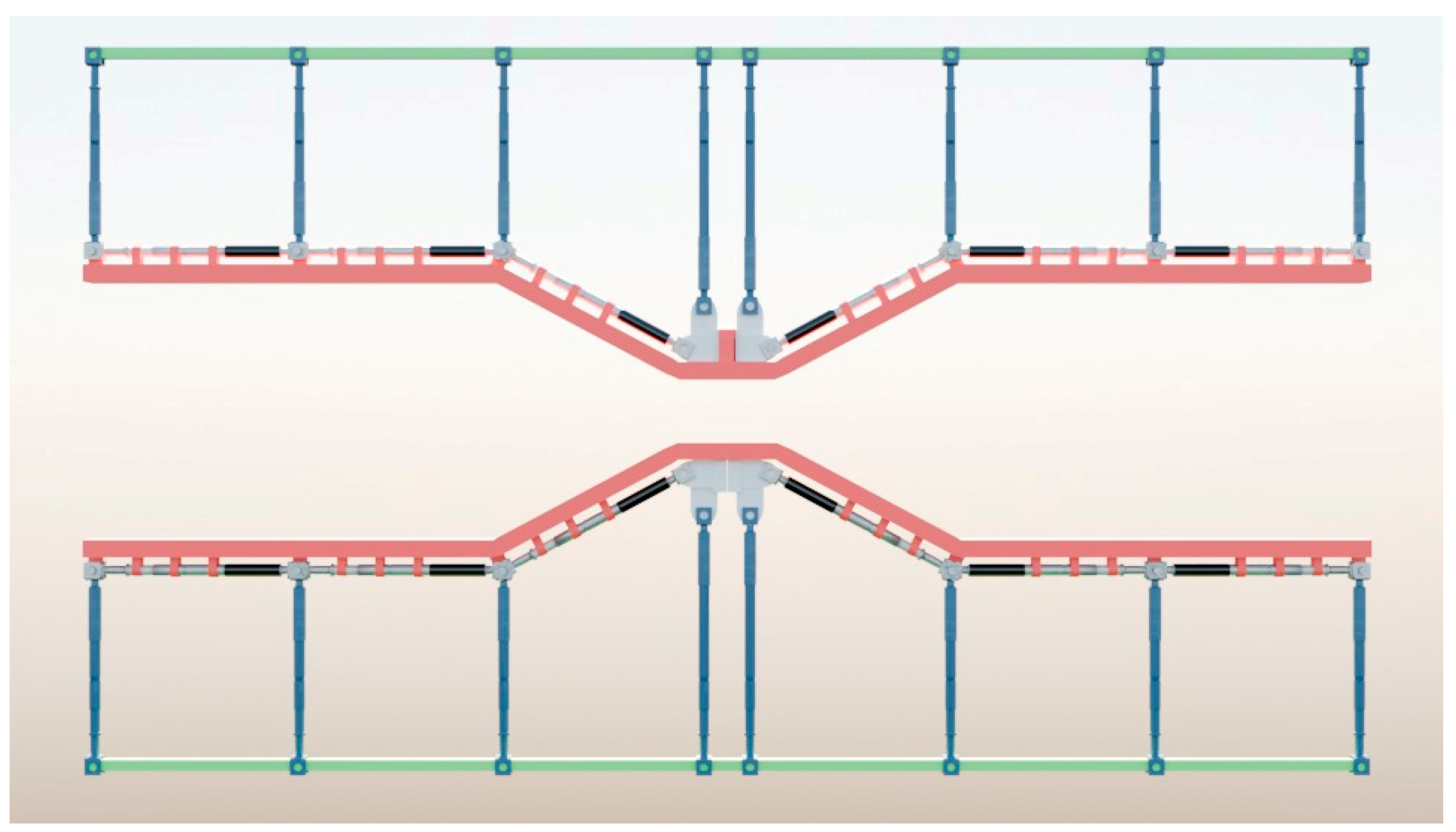
Figure 1.
Schematic DCVA-S in the two limiting configurations, full Venturi view: (a) minimum equivalent throat diameter, ; (b) maximum equivalent throat diameter, . Blue pistons represent the external actuation, white/gray pistons form the kinematic cage, and the red elastomeric liner forms the internal wetted surface.
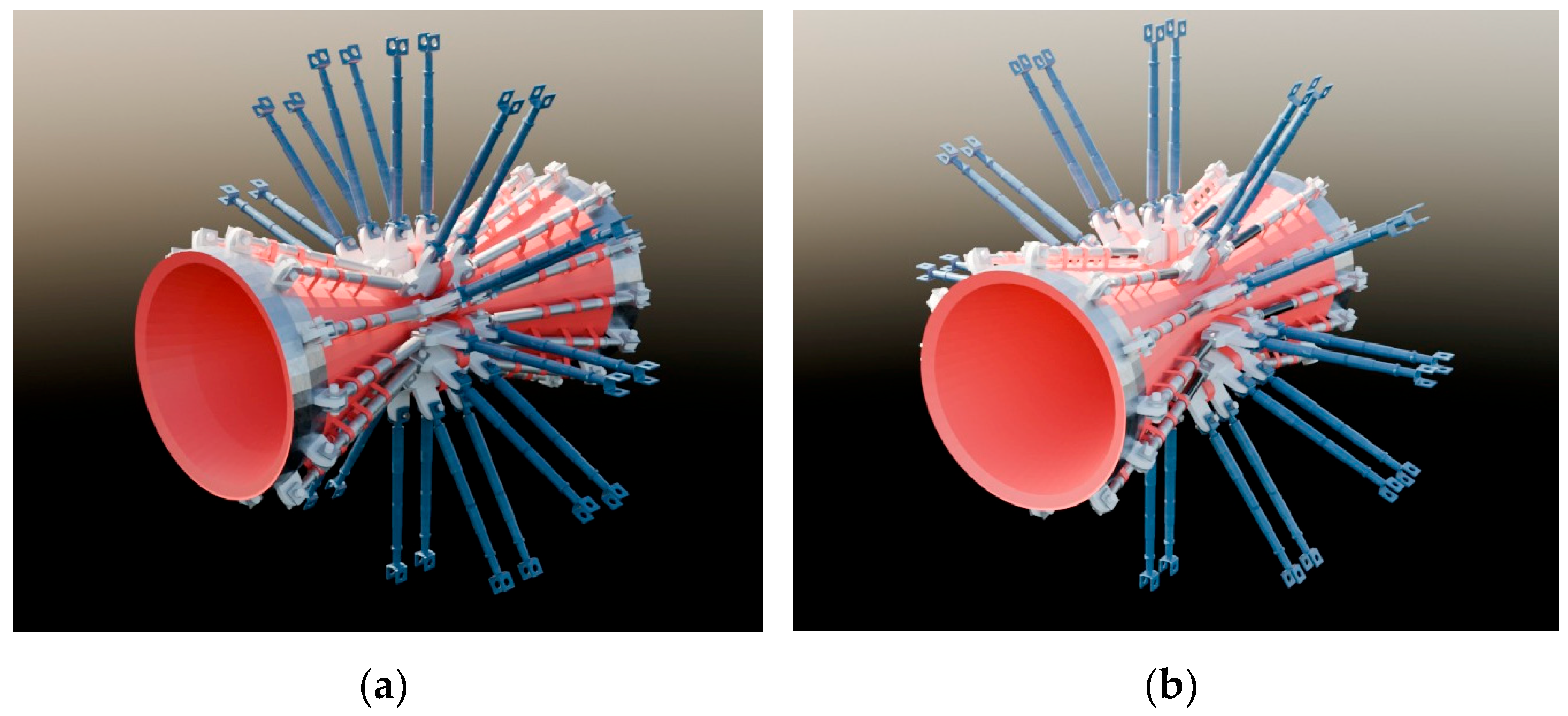
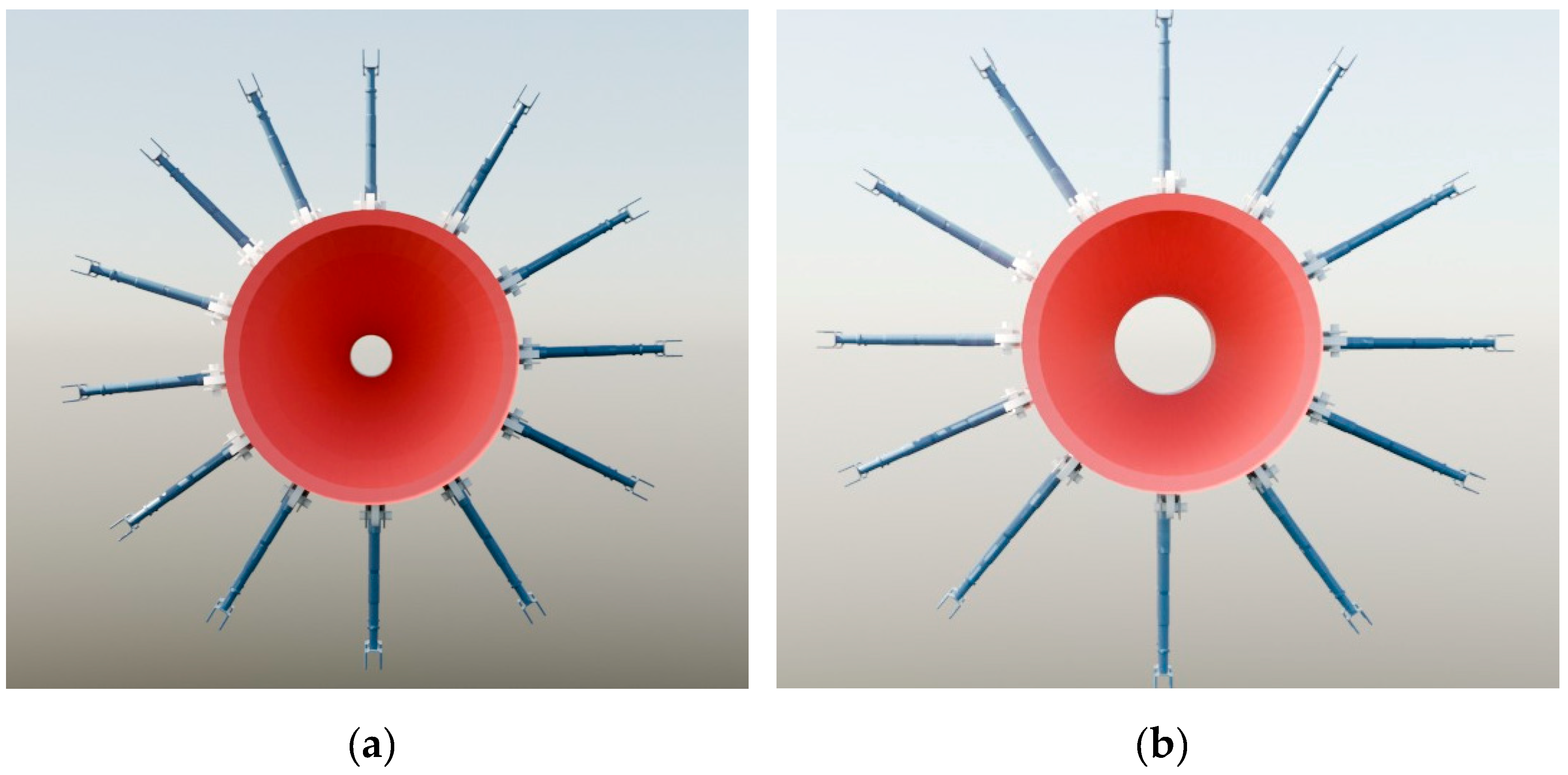
Figure 2.
Schematic front view of the DCVA-S in the two limiting configurations: (a) minimum internal throat section, ; (b) maximum internal throat section, . The external interfaces remain unchanged, while the internal geometry varies.
Figure 2.
Schematic front view of the DCVA-S in the two limiting configurations: (a) minimum internal throat section, ; (b) maximum internal throat section, . The external interfaces remain unchanged, while the internal geometry varies.
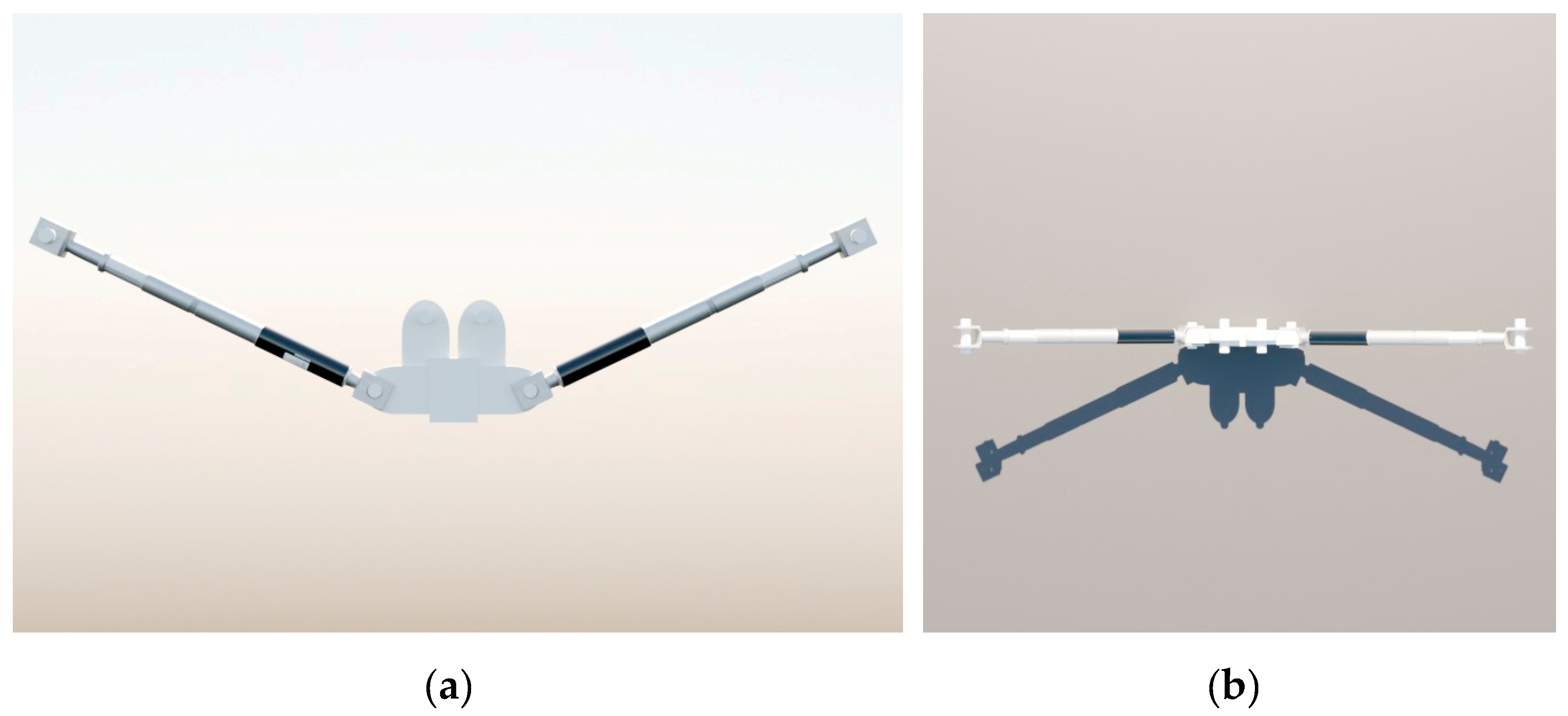
To clarify the modular nature of the kinematic cage, Figure 3 shows the elementary module repeated times along the circumference.
Let denote the number of elementary cage modules distributed around the circumference. Increasing improves the uniformity of the circumferential constraint and, consequently, the repeatability of the resulting internal geometry. Higher values of reduce local deformations between adjacent constraint points and distribute stresses on the liner more uniformly, at the expense of increased mechanical complexity and more demanding assembly/actuation.
Figure 3.
Schematic elementary module of the DCVA-S kinematic cage: (a) front view; (b) top view. The module integrates two linear cage actuators (white pistons) connected to a central body through joints. The upper lugs provide the interface points to the external actuators (blue pistons, not shown). The circumferential repetition of identical modules forms the complete kinematic cage.
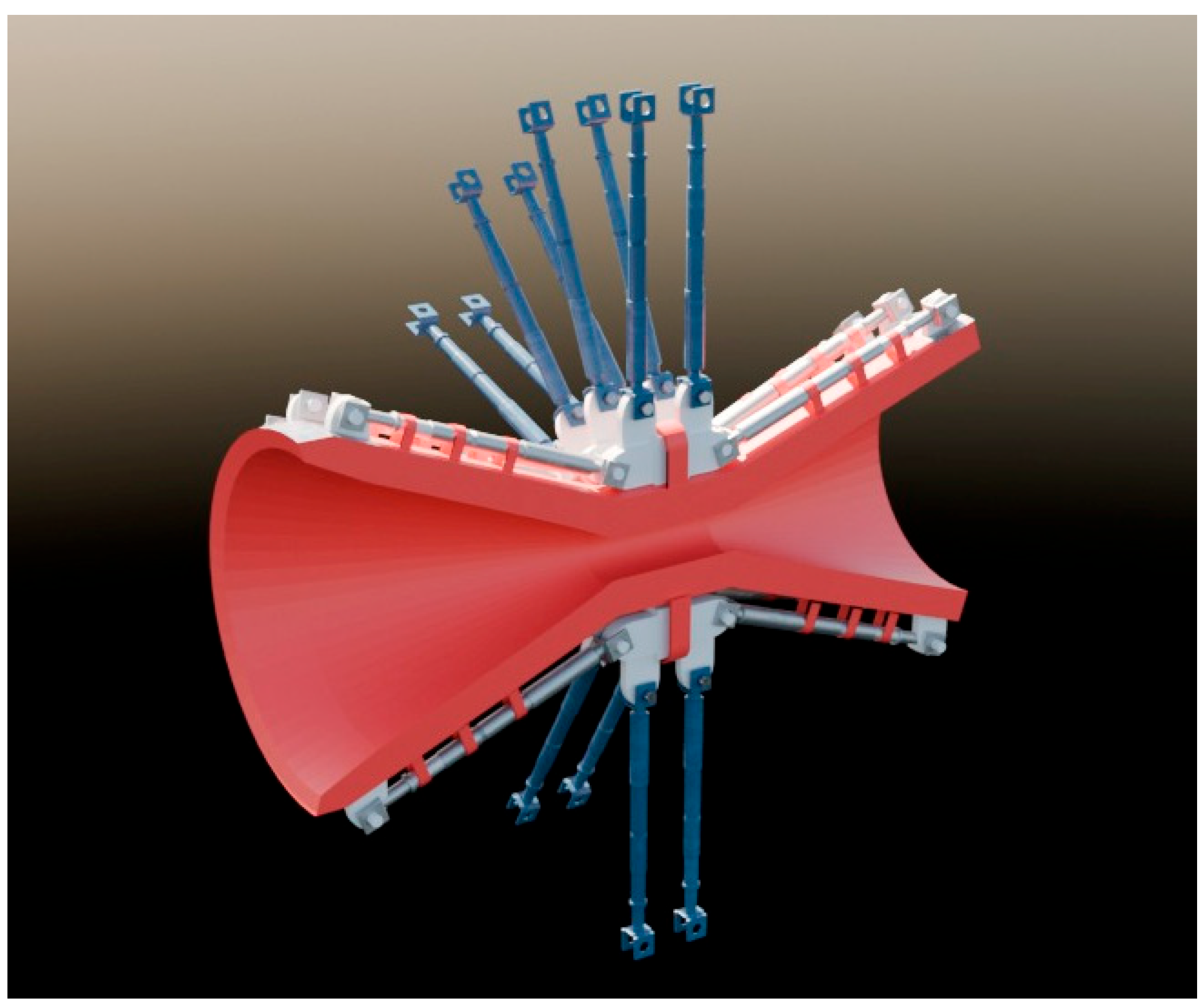
The longitudinal section in Figure 4 highlights the continuity of the internal surface and the transfer of motion to the liner.
Figure 4.
Schematic Longitudinal section of the DCVA-S: the red elastomeric liner, constrained to the white/gray kinematic cage by rings, ensures continuity of the internal surface. Actuation varies , while remains constant due to a mechanical constraint.
Figure 4.
Schematic Longitudinal section of the DCVA-S: the red elastomeric liner, constrained to the white/gray kinematic cage by rings, ensures continuity of the internal surface. Actuation varies , while remains constant due to a mechanical constraint.
3.2. Operation and Kinematics
The reconfiguration of the DCVA-S is described by a single dimensionless parameter , defined within the general framework of Section 2. The control input determines the equivalent throat diameter through the control-to-geometry relation reported in Equation (3).
Consistently with Figure 1, Figure 2, Figure 3 and Figure 4, operation can be summarized as follows. The blue pistons, actuated in a coordinated manner, impose the displacement of the kinematic cage. The cage modules transfer this displacement to the retaining rings. The red liner deforms while maintaining a continuous internal surface, as shown in Figure 4, thereby varying between and , as shown in Figure 1 and Figure 2. The inlet and outlet piping interfaces remain unchanged.
In the DCVA-S, the only actuated degree of freedom is the equivalent throat diameter . The equivalent length of the throat region, , is fixed by design, whereas the effective angles and vary in a coupled manner with and are determined by the kinematics, since they are not independent control variables. The dependencies and can be obtained through geometric or experimental calibration and checked against design limits.
Formally, the DCVA-S explores a one-dimensional subset of the design space , parameterized solely by the equivalent throat diameter:
In Equation (8), denotes the design value of the equivalent length of the throat region, whereas and represent the effective angles induced by the kinematics as varies and can be determined through geometric or experimental calibration.
3.3. Commissioning and Operation
At a conceptual level, the DCVA-S can be operated through a calibration map that links the control input to the internal geometry and to the expected cavitation regime. A commissioning map can be constructed by sampling a discrete set of values and determining the equivalent throat diameter via the control-to-geometry relation in Equation (3), with experimental verification when needed. In the same step, the coupled variation of the effective angles imposed by the kinematics is characterized and checked against the design limits. Using available measurements together with Equations (6) and (7), the operational proxy is then estimated and a – curve or lookup table is constructed.
It is emphasized that is an operational proxy computed from and the equivalent throat diameter through the velocity estimate ; it therefore does not represent a direct measurement of the local cavitation number at the throat. During operation, is selected as a process control variable to achieve the desired cavitation level, for example within a target range of , while satisfying practical plant constraints such as the maximum allowable pressure drop and the mechanical limits of the actuation system.
4. DCVA-M: Multiparametric
The DCVA-M configuration extends the dynamic circular Venturi concept by introducing a multiparametric reconfiguration of the internal profile. The key principle is that the wetted surface is not reconfigured through a single global actuation, but rather through axial stations distributed along the converging section, the throat region, and the diverging section. This architecture generates a family of internal profiles that vary along the axis and enables modulation of the equivalent throat diameter, the shape of the transitions, and the extent of the throat region, while keeping the inlet and outlet piping interfaces unchanged.
4.1. Architecture Multi
The DCVA-M retains an outer cartridge with fixed inlet and outlet connection diameters. Reconfiguration of the internal surface is achieved through axially distributed actuation stations along the Venturi axis. Each station locally sets the radial position of the liner and, through coordinated actuation, generates a family of internal profiles. The color coding of the elements in the figures is kept consistent, with the outer cartridge in green, the liner in red, the actuators in blue, and the kinematic components in white/gray. The external connections remain unchanged, whereas the internal geometry becomes a function of the station commands and can be summarized by the equivalent parameters , , , and .
Station number and spacing set the profile resolution, while actuation and synchronous coordination are implementation-dependent within this framework.
Figure 5.
Longitudinal schematic of the DCVA-M with axially distributed actuation. The red liner forms the internal wetted surface. The blue actuators operate across multiple axial actuation stations, while the white/gray components transfer the displacement to the liner through distributed constraints. This enables a multiparametric reconfiguration of the internal profile while keeping the inlet and outlet piping interfaces unchanged.
4.2. Operation and Parameters
In the DCVA-M, reconfiguration is described by a set of dimensionless control inputs associated with the axial actuation stations. The axial layout is defined by the station locations along the Venturi axis, with . The input of station is denoted by , with . The admissible set of control inputs is defined as
In the following, is assumed.
The resulting internal profile depends on the control vector and defines a family of geometries achievable as varies. Equivalent geometric parameters are introduced to summarize this family. The equivalent throat diameter is defined as the minimum value of the internal profile. The equivalent length of the throat region is defined as the axial extent of the portion close to the minimum according to an operational threshold. The effective inlet and outlet angles, and , are determined as equivalent slopes of the converging and diverging sections through geometric or experimental calibration.
Schematic examples of internal profiles obtained by varying the station control inputs are shown in Figure 6. The figure highlights that multiparametric reconfiguration enables variation not only of , but also of the transition shapes and the extent of the throat region, thereby generating different combinations of , , , and within the design constraints.
4.3. Design Space
The DCVA-M realizes only a subset of the admissible geometries in the design space defined in Equation (5), since the kinematics and actuator limits impose constraints on the reachable configurations. In compact form, the set of achievable configurations is described as:
The functions , , , and capture the effect of the multiparametric reconfiguration enforced by the axially distributed actuation stations and are determined by the device kinematics and calibration. These equivalent parameters are generally not independent. They are coupled through the kinematics and must remain within mechanical and geometric limits. Ensuring axial smoothness of the control inputs is therefore important to prevent overly segmented profiles and to mitigate localized deformation in the liner. Such smoothness can be enforced during calibration and through the selection of admissible operating configurations.
4.4. Calibration and Operation
At a conceptual level, the DCVA-M can be operated through a calibration procedure that associates representative configurations with equivalent internal profiles and expected cavitation levels. Calibration consists of defining a finite set of operating configurations, each characterized by the equivalent values , , , and .
A straightforward operating strategy is to build a catalog of profiles. For each configuration, an expected value of the operational proxy can also be estimated using Equations (6) and (7), based on the equivalent throat diameter of the selected profile and the available measurements. In the multiparametric case as well, is used as an operational proxy based on and , and it does not replace a direct measurement of local cavitation at the throat.
During operation, the operator or the supervisory system selects a configuration from the catalog to achieve the desired cavitation range, while simultaneously satisfying practical plant constraints and the mechanical limits of reconfiguration.
5. Discussion
This A conventional Venturi operates with a fixed geometry and, for given plant conditions, imposes a cavitating operating point that is essentially determined by the throat section. The DCVA introduces a geometric operating variable, since the equivalent throat diameter can be adjusted during operation. For a given flow rate and pressure conditions, varying changes the characteristic throat velocity and allows the cavitation regime to be shifted within a target operating window without altering the external connections.
This aspect is particularly relevant for complex liquids, for which the properties of the process fluid and operating conditions may vary over time. In such cases, a fixed geometry sized for a single operating point may be suboptimal or insufficiently robust. Within the proposed framework, internal reconfiguration decouples plant integration, which remains unchanged, from cavitation-regime control, which becomes adaptable.
In follow-up work, commissioning maps will be extended by parameterizing operating settings versus and relevant fluid properties, and by incorporating thermo-cavitation and suppression mechanisms reported for Venturi devices when required by the specific duty.
Introducing the design space makes it possible to distinguish between the set of admissible geometries and the subset that is actually reachable for a given architecture. In the DCVA-S, exploration is essentially one-dimensional, because the directly actuated degree of freedom is , whereas the equivalent throat-region length and the effective angles are fixed or induced by the kinematics.
In the DCVA-M, reconfiguration is driven by a set of station control inputs belonging to and generates a family of internal profiles. Consequently, the equivalent parameters , , , and vary in a coupled manner as functions of the control input. From this perspective, DCVA-S prioritizes simplicity and repeatability, whereas DCVA-M expands the effectively explorable geometric space at the cost of more articulated kinematic constraints and calibration requirements.
The choice between DCVA-S and DCVA-M can be formulated as a trade-off between geometric flexibility and overall complexity. DCVA-S enables direct modulation of cavitation intensity through with a single control input, making calibration-map-based operation straightforward and keeping the device conceptually simple.
DCVA-M, in contrast, enables adjustment not only of but also of the transition shapes and the extent of the throat region. These aspects influence the pressure-field distribution, flow stability, and the spatial localization of cavitation. In this regard, numerical studies combining cavitation modelling with turbulence closures show that model choices can significantly affect predicted cavitation structures and unsteadiness, which is relevant when assessing the effects of profile reconfiguration. Recent reviews further summarize advances and remaining challenges in cavitation prediction and suppression, providing context for interpreting shifts in cavitation localization and stability induced by geometry changes. This added capability, however, requires a more rigorous definition of admissible configurations, a more extensive calibration procedure, and more careful operational management.
In this work, is used as an operational proxy to link plant-measurable quantities to the equivalent device geometry through . The proxy supports calibration-map construction, configuration comparisons, and the selection of operating settings under a consistent estimation criterion. At the same time, does not replace a direct measurement of the local cavitation number at the throat and should be interpreted in light of the assumptions behind the velocity estimate and the presence of distributed losses.
For engineering reproducibility, the DCVA concepts are specified through the key geometric and kinematic parameters summarized in Table 1; application-specific dimensions and material choices are not prescribed in this sector-agnostic framework, and repeatability is addressed during commissioning by measuring the relevant geometry mappings.
Adopting the DCVA also introduces constraints that affect both design and operation. The repeatability of the equivalent geometry may be influenced by hysteresis and mechanical tolerances, while liner durability depends on stress distribution and cyclic deformation. Accordingly, material selection can draw on recent developments in sustainable elastomers and durability-oriented design approaches, on EPDM-based compatibilization strategies to improve low-temperature robustness, and on nano-carbon reinforcement routes for high-performance elastomers under cyclic loading.
The DCVA can be used as a reusable tool to explore and identify the optimal cavitation operating window in a given application, for example in food processing to maximize a target extraction, and then be moved to a different context such as water treatment to optimize the removal of a specific pollutant; once the optimal window is identified, a dedicated static Venturi can be manufactured for continuous operation.
Accordingly, the DCVA is benchmarked in follow-up work through system-level metrics rather than performance claims, including the achievable regime-modulation range with unchanged in-line interfaces, the commissioning effort to identify a robust operating window, and the transfer from exploratory tuning to a finalized static Venturi for continuous duty.
Although the present study is conceptual and does not report a complete experimental validation, deployment in process plants can be supported by essential verification steps. These include calibrating the control-to-geometry relationship to obtain and, when relevant, the other equivalent parameters; constructing control– maps under nominal conditions; verifying the operating window in terms of pressure drop; and qualitatively correlating variations in with independent cavitation indicators to support proxy interpretation.
6. Conclusions
This work presents a conceptual system design framework for the Dynamic Circular Venturi (DCVA), a reconfigurable circular Venturi conceived as a drop-in in-line replacement. The device preserves the external body and the inlet and outlet piping interfaces while making the internal throat configuration a design and operating degree of freedom. A formalism based on equivalent geometric parameters and a dedicated design space is defined, and two representative architectures are described, namely a single degree-of-freedom configuration and a multiparametric configuration. An operational proxy indicator is also introduced, computable from quantities typically available in process plants, to support configuration selection and unambiguous specification of operating settings when local throat pressure is not directly accessible. No experimental campaign or high-fidelity CFD results are reported, as the present contribution is intended as a conceptual design framework rather than a performance-validation study.
The proposed framework is directly relevant to sustainable food-processing duties where hydrodynamic cavitation is used as a green process-intensification route, because controllable throat modulation can support robust operation, resource-efficiency improvements, and waste minimization.
Quantitative evidence will be generated in follow-up work for a selected industrial duty by measuring the command–geometry mappings and their repeatability under cycling, constructing commissioning maps linking configuration and plant conditions to cavitation indicators and process targets while verifying pressure-drop constraints, and correlating and configuration changes with independent cavitation diagnostics and process outcomes. When required by the duty, numerical analysis can be used to support interpretation under specified boundary conditions.
Funding
This research received no external funding.
Data Availability Statement
The original contributions presented in this study are included in the article. Further inquiries can be directed to the corresponding author.
Conflicts of Interest
The author declares no conflicts of interest.
Abbreviations
The following abbreviations are used in this manuscript:
| DCVA | Dynamic Circular Venturi |
| DCVA‐S | Dynamic Circular Venturi Single‐parameter |
| DCVA‐M | Dynamic Circular Venturi Multiparametric |
References
- A Panda, D.; Saharan, V.K.; Manickam, S. Controlled Hydrodynamic Cavitation: A Review of Recent Advances and Perspectives for Greener Processing. Processes 2020, 8, 220. [Google Scholar] [CrossRef]
- Carpenter, J.; Badve, M.; Rajoriya, S.; Pandit, A.B. Hydrodynamic Cavitation: An Emerging Technology for the Intensification of Various Chemical and Physical Processes in a Chemical Process Industry. Rev. Chem. Eng. 2017, 33, 433–468. [Google Scholar] [CrossRef]
- Arya, S.S.; More, P.R.; Ladole, M.R.; Pegu, K.; Pandit, A.B. Non-thermal, Energy Efficient Hydrodynamic Cavitation for Food Processing, Process Intensification and Extraction of Natural Bioactives: A Review. Ultrason. Sonochem. 2023, 98, 106504. [Google Scholar] [CrossRef]
- Zoglopiti, E.; Roufou, S.; Psakis, G.; Okafor, E.T.; Dasenaki, M.; Gatt, R.; Valdramidis, V.P. Unravelling the Hydrodynamic Cavitation Potential in Food Processing: Underlying Mechanisms, Crucial Parameters, and Antimicrobial Efficacy. Food Eng. Rev. 2025. [Google Scholar] [CrossRef]
- Wu, Z.; Ferreira, D.F.; Crudo, D.; Bosco, V.; Stevanato, L.; Costale, A.; Cravotto, G. Plant and Biomass Extraction and Valorisation under Hydrodynamic Cavitation. Processes 2019, 7, 965. [Google Scholar] [CrossRef]
- Petkovšek, M.; Zupanc, M.; Dular, M.; Kosjek, T.; Heath, E.; Kompare, B.; Širok, B. Rotation Generator of Hydrodynamic Cavitation for Water Treatment. Sep. Purif. Technol. 2013, 118, 415–423. [Google Scholar] [CrossRef]
- Viswanathan, S. Development of a Pressure Drop Model for a Variable Throat Venturi Scrubber. Chem. Eng. J. 1998, 71, 153–160. [Google Scholar] [CrossRef]
- Brady, J.D.; Legatski, L.K. Variable Throat Venturi Scrubber. U.S. Patent US4023942A, 1977. [Google Scholar]
- Tian, H.; Zeng, P.; Yu, N.; Cai, G. Application of Variable Area Cavitating Venturi as a Dynamic Flow Controller. Flow Meas. Instrum. 2014, 38, 21–26. [Google Scholar] [CrossRef]
- Tan, G.; Tian, H.; Gu, X.; Meng, X.; Wei, T.; Zhang, Y.; Cai, G. Flow Feedback Control Based on Variable Area Cavitating Venturi and Its Application in Hybrid Rocket Motors. Acta Astronaut. 2023, 211, 238–248. [Google Scholar] [CrossRef]
- Long, X.; Sun, M.; Chen, L.; et al. Research on Cavitation and Oscillation Transition Mechanism of Adjustable Cavitation Venturi Tube. J. Hydrodyn. 2025, 37, 680–697. [Google Scholar] [CrossRef]
- Albanese, L.; Centritto, M.; Meneguzzo, F. Apparatus for Dynamically Regulating Hydrodynamic Cavitation Processes and Related Process. European Patent EP4260934A1, 2023. [Google Scholar]
- Simpson, A.; Ranade, V.V. Modeling Hydrodynamic Cavitation in Venturi: Influence of Venturi Configuration on Inception and Extent of Cavitation. AIChE J. 2019, 65, 421–433. [Google Scholar] [CrossRef]
- Brennen, C.E. Cavitation and Bubble Dynamics; Oxford University Press: Oxford, UK, 1995. [Google Scholar] [CrossRef]
- Franc, J.-P.; Michel, J.-M. Fundamentals of Cavitation; Kluwer Academic Publishers: Dordrecht, The Netherlands, 2004. [Google Scholar] [CrossRef]
- Rütten, E.; Leister, N.; Karbstein, H.P.; Håkansson, A. Possibilities and Limits of Modeling Cavitation in High-Pressure Homogenizers—A Validation Study. Chem. Eng. Sci. 2024, 283, 119405. [Google Scholar] [CrossRef]
- Tan, G.; Tian, H.; Lv, G. Experimental Study on Flow Coefficient of Variable Area Cavitating Venturi. In Proceedings of the 8th International Conference on Manufacturing, Material and Metallurgical Engineering (ICMMME 2024); Lecture Notes in Mechanical Engineering; Agarwal, R.K., Ed.; Springer: Cham, Switzerland, 2025. [Google Scholar] [CrossRef]
- ISO. ISO 37:2017; Rubber, Vulcanized or Thermoplastic—Determination of Tensile Stress–Strain Properties. International Organization for Standardization: Geneva, Switzerland, 2017.
- Wang, G.; Senocak, I.; Shyy, W.; Ikohagi, T.; Cao, S. Dynamics of Attached Turbulent Cavitating Flows. Prog. Aerosp. Sci. 2001, 37, 551–581. [Google Scholar] [CrossRef]
- Lee, H.; Lee, C.; Kim, M.-S.; Seok, W. Numerical Investigation of Cavitation Models Combined with RANS and PANS Turbulence Models for Cavitating Flow Around a Hemispherical Head-Form Body. J. Mar. Sci. Eng. 2025, 13, 821. [Google Scholar] [CrossRef]
- Qiu, Q.; Gu, Y.; Ren, Y.; Mou, C.; Hu, C.; Ding, H.; Wu, D.; Wu, Z.; Mou, J. Research Progress in Hydrofoil Cavitation Prediction and Suppression Methods. Phys. Fluids 2025, 37, 011301. [Google Scholar] [CrossRef]
- Filippova, O.V.; Maksimkin, A.V.; Dayyoub, T.; Larionov, D.I.; Telyshev, D.V. Sustainable Elastomers for Actuators: “Green” Synthetic Approaches and Material Properties. Polymers 2023, 15, 2755. [Google Scholar] [CrossRef]
- Liu, G.; Du, F.; Yao, Z.; Li, G.; Kuang, W.; Zhu, C.; Liu, Y.; Chen, H.; Wang, F.; Zhou, C.; et al. Effects of Ethylene Propylene Diene Monomer (EPDM)-Based Polar Macromolecular Compatibilizers on the Low-Temperature Properties of Fluoroelastomer/EPDM Rubber Blends. Molecules 2024, 29, 5522. [Google Scholar] [CrossRef] [PubMed]
- Valentini, L.; López-Manchado, M.A. (Eds.) High-Performance Elastomeric Materials Reinforced by Nano-Carbons: Multifunctional Properties and Industrial Applications; Elsevier: Amsterdam, The Netherlands, 2020; ISBN 978-0-12-816198-2. [Google Scholar] [CrossRef]
- Zheng, H.; Zheng, Y.; Zhu, J. Recent Developments in Hydrodynamic Cavitation Reactors: Cavitation Mechanism, Reactor Design, and Applications. Engineering 2022, 19, 180–198. [Google Scholar] [CrossRef]
- Ghassemi, H.; Farshi Fasih, H. Application of small size cavitating venturi as flow controller and flow meter. Flow Measurement and Instrumentation 2011, 22, 406–412. [Google Scholar] [CrossRef]
- Mena, J. L.; Ingle, M. A.; Shirsat, V.; Choudhuri, A. An investigation of a cavitating venturi flow control feature in a cryogenic propellant delivery system. Flow Measurement and Instrumentation 2015, 41, 97–103. [Google Scholar] [CrossRef]
- Ashrafizadeh, S. M.; Ghassemi, H. Experimental and numerical investigation on the performance of small-sized cavitating venturis. Flow Measurement and Instrumentation 2015, 42, 6–15. [Google Scholar] [CrossRef]
- Ge, M.; Petkovšek, M.; Zhang, G.; Jacobs, D.; Coutier-Delgosha, O. Cavitation Dynamics and Thermodynamic Effects at Elevated Temperatures in a Small Venturi Channel. Int. J. Heat Mass Transf. 2021, 170, 120970. [Google Scholar] [CrossRef]
- Ge, M.; Sun, C.; Zhang, G.; Coutier-Delgosha, O.; Fan, D. Combined Suppression Effects on Hydrodynamic Cavitation Performance in Venturi-Type Reactor for Process Intensification. Ultrason. Sonochem. 2022, 86, 106035. [Google Scholar] [CrossRef] [PubMed]
Figure 6.
Schematic examples of internal profiles obtained by varying the station control inputs. The profiles are illustrative, not extracted from simulations or experiments, and show how multiparametric reconfiguration can vary , transition shapes, and throat extent, generating different combinations of , , , and within design constraints.
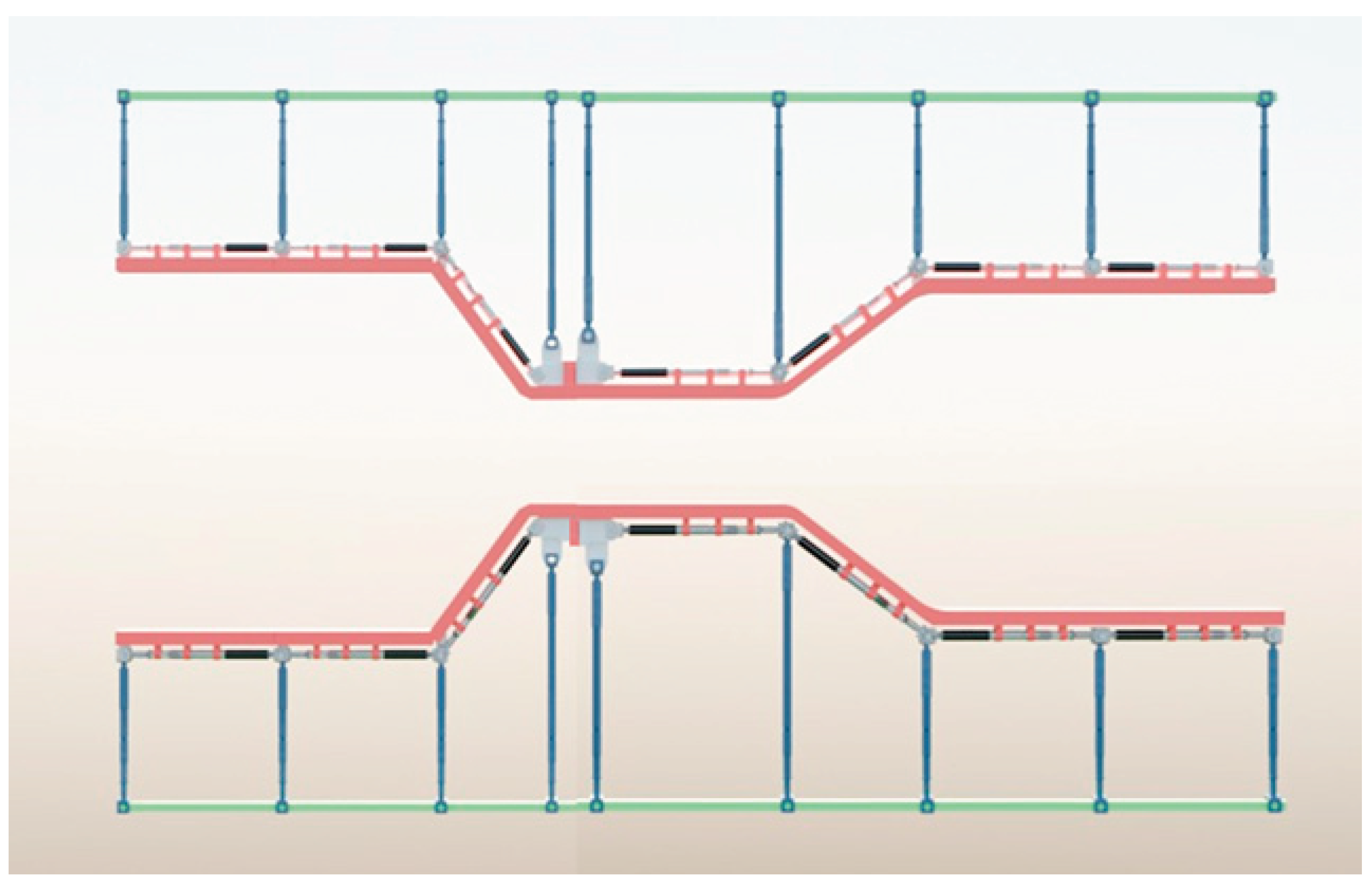

Table 1.
Key parameters used to describe DCVA architectures within the present framework.
| DCVA | DCVA-S | DCVA-M |
|---|---|---|
| | | |
| | | |
| | | |
| | ||
| | ||
| |
Note: In DCVA-S the geometry state is controlled by , whereas in DCVA-M it is controlled by the station commands ; the station layout is defined by the axial locations .
Disclaimer/Publisher’s Note: The statements, opinions and data contained in all publications are solely those of the individual author(s) and contributor(s) and not of MDPI and/or the editor(s). MDPI and/or the editor(s) disclaim responsibility for any injury to people or property resulting from any ideas, methods, instructions or products referred to in the content. |
© 2026 by the authors. Licensee MDPI, Basel, Switzerland. This article is an open access article distributed under the terms and conditions of the Creative Commons Attribution (CC BY) license (http://creativecommons.org/licenses/by/4.0/).
Copyright: This open access article is published under a Creative Commons CC BY 4.0 license, which permit the free download, distribution, and reuse, provided that the author and preprint are cited in any reuse.


