
Submitted:
14 February 2026
Posted:
25 February 2026
You are already at the latest version
Abstract
The increasing occurrence of persistent and bio-recalcitrant organic pollutants in aquatic environments necessitates the development of more resilient and efficient water treatment technologies. Conventional treatment processes often fail to remove such stable contaminants, prompting growing interest in integrated advanced systems. Photocatalytic membranes represent a promising solution due to the synergistic combination of separation and catalytic degradation. In this study, ZnO thin films were deposited by spin coating onto smectite–zeolite ceramic membranes (MS10/Z90), with one to three layers applied to control catalyst thickness (M1–M3). SEM analysis showed that increasing the number of layers led to a thicker, more homogeneous ZnO coating, while XRD confirmed enhanced crystallinity and larger crystallite size. Water permeability decreased from 623 L.h-1.m-2.bar-1 for the uncoated MS10/Z90 membrane to 506, 439, and 350 L.h-1.m-2.bar-1 respectively for M1, M2, and M3 after coating. Photocatalytic performance was assessed using Rhodamine B (RhB) as a model dye, achieving degradation efficiencies of 83.0%, 94.6%, and 99.1% for M1, M2, and M3, respectively, following pseudo-first-order kinetics. The free radical scavenging assays confirmed that hydroxyl radicals (•OH) were responsible for the RhB conversion.These results highlight the key influence of ZnO layer thickness and mass transfer on photocatalytic performance, de-monstrating the multifunctionality of ZnO-coated membranes, including efficient pollu-tant degradation and self-cleaning capability.
Keywords:
photocatalytic membrane
; RhB dye degradation
; self-cleaning
; ZnO deposition
; spin coating
1. Introduction
Industrial activities remain one of the primary drivers of global water pollution, as industrial effluents contain complex mixtures of refractory organic pollutants [1], inorganic salts, heavy metals, and toxic compounds that are poorly removed by conventional treatment processes [2]. Among these sectors, the textile industry is particularly water-intensive [3], consuming approximately 230-270 tons of water per ton of product, which results in the discharge of large volumes of highly colored and chemically complex wastewater into aquatic environments [4]. Among synthetic dyes, cationic dyes such as Rhodamine B (RhB) are of particular concern due to their high molecular stability, resistance to biodegradation, and strong affinity for aquatic systems [5]. RhB is widely used in the textile, rubber, and paper industries and is frequently detected in industrial effluents at concentrations ranging from 20 to 300 mg L-1[6]. This dye is associated with toxic, mutagenic, and potentially carcinogenic effects (Group 3 classification) and can disrupt aquatic ecosystems even at trace concentrations. Therefore, its efficient removal requires advanced treatment technologies capable of both separation and degradation [7].
Membrane-based separation processes have emerged as a key technology for dye removal owing to their high rejection efficiency, compact design, and operational flexibility [8],[9]. However, their long-term performance is severely constrained by membrane fouling, which arises from the adsorption, deposition, and concentration polarization of pollutants on the membrane surface and within its pores [10]. This phenomenon leads to flux decline, increased transmembrane pressure, higher energy consumption, and reduced membrane lifespan, particularly in highly contaminated effluents [11,12].
In parallel, photocatalysis has been extensively investigated as a promising oxidation process for the mineralization of organic pollutants through the generation of reactive oxygen species (•OH, O2•-, H2O2) under light irradiation [13]. Nevertheless, conventional slurry-based photocatalytic systems present major limitations, including catalyst agglomeration, nanoparticle loss, difficult post-treatment recovery, and reduced efficiency at high pollutant loads due to light scattering and limited photon penetration [14].
To overcome these challenges, the integration of membrane filtration with photocatalysis into a single hybrid system has gained significant attention [15]. Immobilizing photocatalytic materials onto a membrane surface enables simultaneous physical separation and in situ oxidative degradation of pollutants, preventing catalyst loss while promoting continuous self-cleaning of the membrane under light irradiation and improving permeability recovery [16].
Over the past decade, several studies have demonstrated the potential of photocatalytic ceramic membranes. In this context, zinc oxide (ZnO) has emerged as a highly promising photocatalytic surface modifier owing to its favorable semiconductor properties, strong photoactivity, and chemical stability. Baig et al. [17] showed that ZnO thin films deposited on alumina membranes via RF magnetron sputtering form a uniform, stable coating with pronounced photoresponsiveness, attributed to efficient photogenerated charge separation under light irradiation. Kuang et al. [18] further demonstrated that ZnO layers grown on Al₂O₃ supports enhance photocatalytic performance through effective light absorption and electron–hole pair formation while maintaining strong interfacial adhesion with the ceramic substrate. In addition, Wei et al. [19] reported that ZnO nanoflower architectures provide a high specific surface area and abundant active sites, significantly boosting photocatalytic reactivity when integrated onto ceramic membranes. Earlier investigations by Huang et al. [20] also confirmed that nanostructured ZnO coatings promote enhanced generation of reactive oxygen species (ROS) and improve surface redox activity, which are critical for efficient degradation of organic pollutants. Collectively, these studies indicate that the photocatalytic performance of ZnO-decorated ceramic membranes is strongly governed by ZnO morphology, coating uniformity, crystallinity, and interfacial stability with the membrane support. Despite these promising advances, most existing photocatalytic membrane systems still rely on solar irradiation or complex reactor configurations [21], and many studies have focused on oily wastewater rather than dye-laden effluents such as Rhodamine B. This highlights the need for simpler, more robust, and controllable photocatalytic membrane systems operating under artificial light sources and specifically tailored for highly colored textile wastewater [22].
This work aims to develop a novel ZnO-functionalized ceramic membrane that integrates size-selective filtration and intrinsic photocatalytic self-cleaning within a single, robust platform for dye-contaminated wastewater treatment. The membrane is rationally designed by coating a mesoporous ceramic support with immobilized nanostructured ZnO, forming a bifunctional interface capable of simultaneously retaining RhB and photocatalytically degrading it at the membrane water interface under light irradiation. Unlike conventional membranes that suffer from surface fouling, the proposed system directly mineralizes the accumulated organic layer in situ through reactive oxygen species generated by ZnO, thereby addressing fouling at its origin rather than through periodic external cleaning. The novelty of this study lies in the implementation of a fixed-bed, submerged multilayer ceramic photocatalytic membrane reactor that eliminates catalyst leaching, avoids slurry handling and post-recovery steps, and ensures reproducible photocatalyst activation using an external artificial light source. By combining separation and degradation in a single reusable membrane, this approach enables sustained permeate flux, reduced maintenance and energy demand, and extended membrane lifespan, offering a sustainable and operationally viable alternative to existing photocatalytic membrane systems.
2. Materials and Methodology
2.1. Chemicals
Zinc oxide (ZnO), polyvinyl alcohol (PVA (98.99)), and Rhodamine B were employed in this study and were acquired from Sigma Aldrich. Table 1 summarizes the key properties of the used model dye. The flat ceramic support (MS10/Z90), composed of zeolite and smectite, has been described in detail in a previous study [21] (Table 2).
2.2. Deposition of ZnO Thin Film Active Layer on Support MS10/Z90 Using Spin Coating
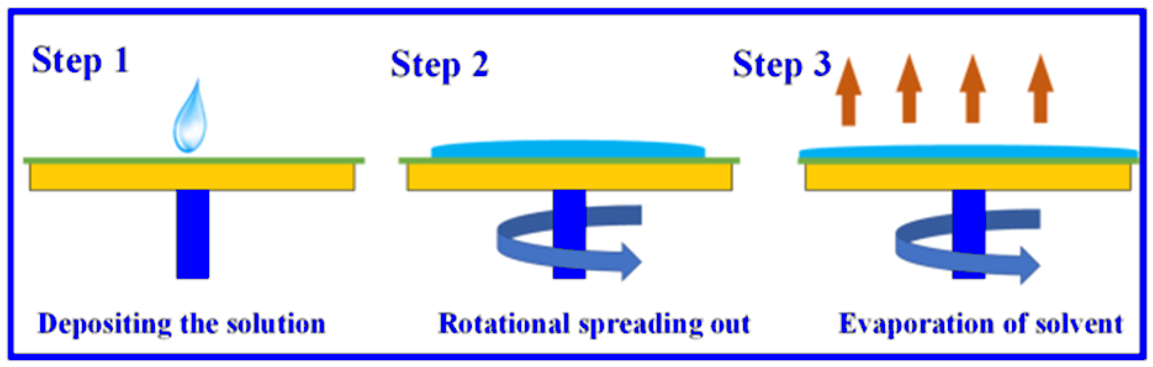
The active layer was fabricated from ZnO powder using a spin-coating technique[23] applied to the MS10/Z90 substrate [24]. The coating solution was prepared by dispersing ZnO particles in water using polyvinyl alcohol (PVA) as a binder, followed by homogenization with a magnetic stirrer
The fabrication process began with careful preparation of the substrate. One side of the ceramic support was polished to ensure surface uniformity, followed by ultrasonic cleaning in deionized water to remove abrasive residues and contaminants. The substrate was then dried overnight in an oven at 105 °C to achieve a completely dry and thermally stable surface, providing an optimal foundation for the functional layer.
The coating suspension was synthesized by preparing two separate solutions: ZnO powder dispersed in water to form suspensions of varying concentrations, and an aqueous PVA solution serving as the binding agent. Equal volumes of these solutions were blended and homogenized using ultrasonic energy, yielding a stable colloidal mixture. Multiple coating layers of this suspension were applied to fabricate membranes with varying ZnO loadings. The resulting lines deposited on the membrane surface are detailed in the Table 3.
Deposition was performed using a centrifugal coating method. A precise volume of the colloidal suspension was dispensed onto the rotating substrate at a controlled flow rate. Spinning at 400 rpm ensured uniform spreading of the liquid across the surface, while centrifugal force expelled the excess, forming a consistent thin film.
The consolidation phase involved a carefully controlled thermal treatment. The freshly coated membrane was first air-dried for 24 hours to allow gradual solvent evaporation. It then underwent a two-stage heating process: binder removal at 300 °C to pyrolyze the organic PVA, followed by sintering at 500 °C to densify the ZnO structure [25]. This sintering temperature was chosen to enhance ZnO crystallinity and photocatalytic activity while preventing excessive grain growth and preserving membrane integrity.
Figure 1.
Centrifugal coating process for thin-film deposition: (1) solution deposition, (2) rotational spreading, (3) solvent evaporation.
Figure 1.
Centrifugal coating process for thin-film deposition: (1) solution deposition, (2) rotational spreading, (3) solvent evaporation.
2.3. Membrane Characterization
The membranes were characterized using Fourier Transform Infrared Spectroscopy (FTIR, Spectrum 100, PerkinElmer, Waltham, MA, USA) and X-ray Diffraction (XRD, D8 Advance diffractometer, Bruker, Billerica, MA, USA). XRD measurements were carried out with Cu Kα radiation (λ = 1.5406 Å) over a 2θ range of 4-80°. The surface morphology of the membranes was further examined using scanning electron microscopy (SEM, Hitachi S4800, Tokyo, Japan). Also, the chemical composition of the membrane samples was detected using energy-dispersive spectroscopy (EDX) and elemental mapping analysis.
Membrane porosity (ε) was determined according to Archimedes’ principle. The membrane sample was first dried at 100 °C for 6 h and weighed to obtain the dry mass (W₁). It was then immersed in deionized water for 24 h to ensure complete saturation. After carefully removing excess surface water, the saturated membrane was weighed to determine the wet mass (W₂). The porosity was subsequently calculated using Equation (1),
Where W₁ and W₂ represent the dry and wet membrane weights, Vmem corresponds to the membrane volume, and ρwater denotes the density of water.
2.4. Membrane Performance
Membrane permeability was assessed at a temperature of 25 °C and a transmembrane pressure (TMP) ranging between 1 and 3 bar using distilled water. Before experiments, the membrane was conditioned by immersion in distilled water for at least 24 h. The working pressure was kept constant using a nitrogen gas source. The membrane's permeability was determined using the variation of distilled water flux Jw (L.h−1.m−2) with TMP (bar) according to Darcy's law (equation (3)) [26]:
In this study, the photocatalytic activity of the samples was assessed by monitoring the degradation of RhB under UV irradiation. A schematic of the photoreactor is shown in Figure 2. The experiments were conducted in a double-jacketed glass reactor (total volume: 0.2 L) containing 150 mL of RhB solution at an initial concentration of 10 mg.L-1. This concentration was selected as it is widely used in photocatalytic studies, enabling comparison with previous results[27];[28]. In addition, 10 mg·L⁻¹ provides sufficient absorbance for accurate spectrophotometric analysis without significant mass transfer or light-screening effects. A UV lamp (λ = 365 nm, 18 W) was positioned at a distance of approximately 3 cm from the sample surface. Aliquots of the solution were withdrawn every 30 minutes to evaluate the progress of RhB degradation.
The extent of RhB discoloration was quantified using a UV–Vis spectrophotometer (UV-3100 PC, China) at 556 nm, corresponding to the maximum absorbance of RhB [23]. The photocatalytic degradation efficiency was calculated according to Equation (2).
2.5. Kinetics Study
The photocatalytic degradation kinetics of pollutants in the aqueous phase are described using the Langmuir-Hinshelwood model [24].
In this model, r is the reaction rate (mg.L-1min-1), C is the pollutant concentration (mg.L-1), k is the Langmuir-Hinshelwood reaction rate constant (mg.L-1.min-1), and K is the Langmuir adsorption equilibrium constant (L.mg-1).
At dilute pollutant concentrations (i.e., KC << 1), the pseudo-first-order kinetics model can be applied: where Kapp is the apparent rate constant (min-1) and C0 is the initial concentration of pollutants (mgL-1).
Where :
- = apparent rate constant (min⁻¹)
- = initial concentration of the pollutant (mg.L-1)
- = concentration of the pollutant at time (mg.L-1)
- = reaction time (min).
3. Results and Discussion
3.1. Membrane Characterization
3.1.1. XRD Analysis
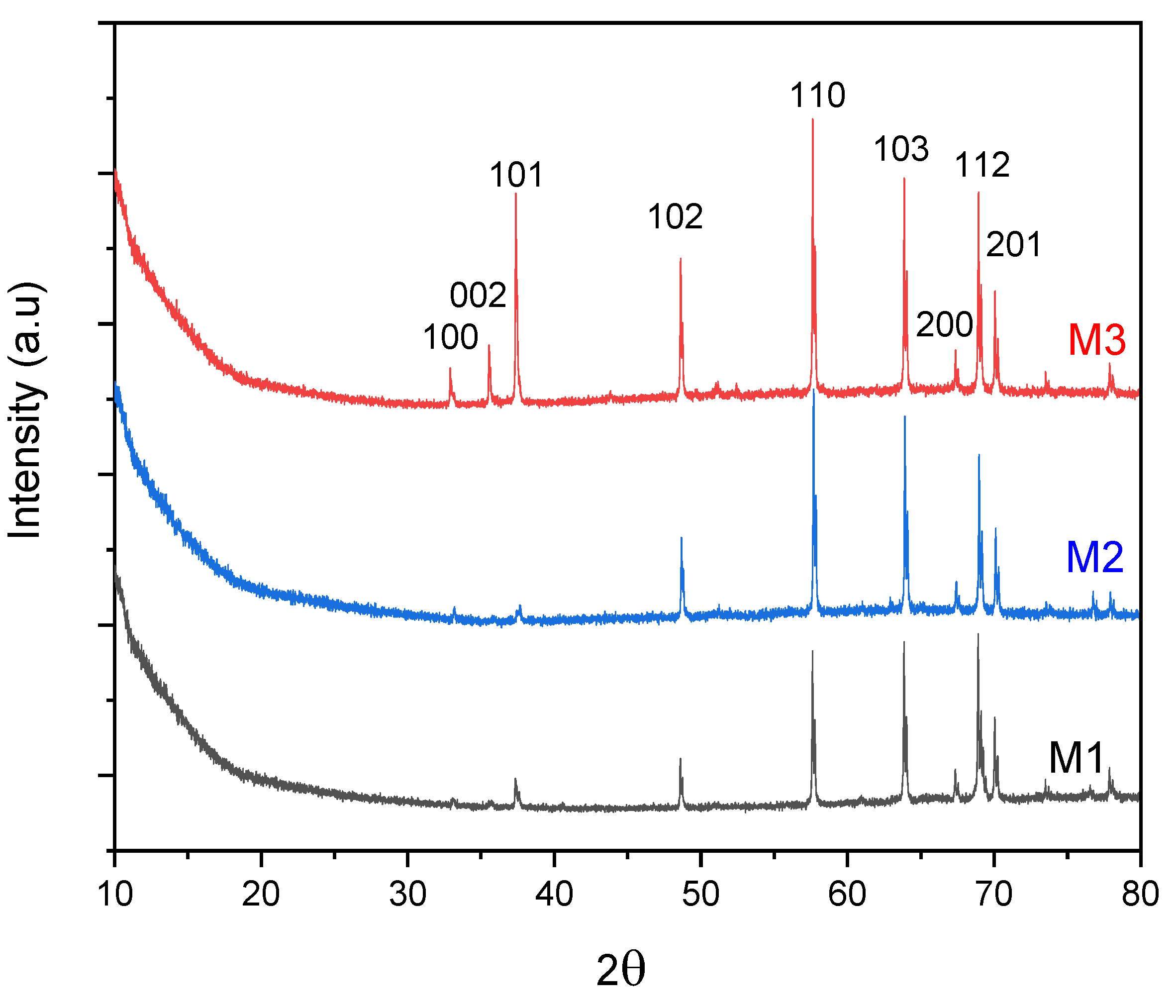
The XRD patterns of samples M1, M2, and M3 clearly demonstrate the systematic effect of increasing ZnO layer thickness on their crystalline structure. As the ZnO thickness increases, the intensity of the diffraction peaks characteristic of the hexagonal wurtzite phase progressively increases, indicating a larger crystalline volume and enhanced overall crystallinity [25]. The detected reflections correspond to the ZnO crystallographic planes (110), (103), (200), (112), (201), (004), and (202), in good agreement with the standard data reported in JCPDS card No. 36-1451, are observed for all three membranes. Additionally, new diffraction peaks indexed to the (002), (101), and (102) planes appear in sample M3, suggesting improved crystallinity and the development of preferential orientations at higher thicknesses. These findings are consistent with previously reported studies, which indicate that thicker ZnO films generally exhibit superior crystalline quality [25].
Figure 3.
X-ray diffraction (DRX) patterns of M1,M2, and M3membranes.
3.1.2. FTIR Analysis
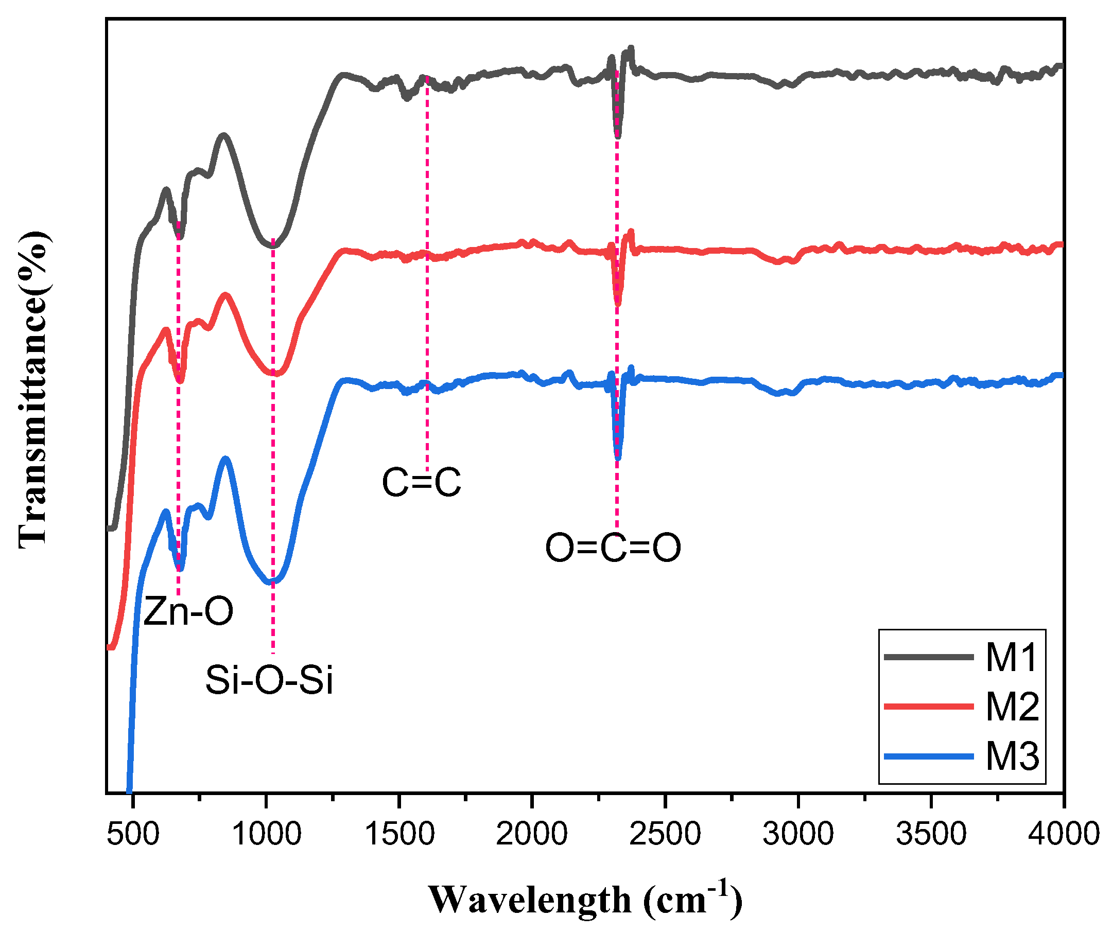
The FTIR spectra reveal the evolution of absorption bands as the ZnO layer thickness increases in membranes M1, M2, and M3. A progressive reduction in overall transmittance from M1 to M3 is consistent with the Beer-Lambert law, since thicker layers contain more light-absorbing material and thus attenuate infrared transmission more strongly [29]. In the low-frequency region (400-600 cm-1), the characteristic Zn-O vibration band becomes increasingly pronounced, indicating a larger volume of crystallized ZnO within the film[30].
At higher frequencies, the broad absorption feature between 3200 and 3600 cm⁻¹, attributed to surface-adsorbed hydroxyl groups or water, appears slightly more defined in thicker films. This enhancement may arise from increased surface roughness, porosity, or simply the greater material thickness probed by the infrared beam[31]. Sharp peaks observed near 2350 cm-1are unrelated to the ZnO film and correspond instead to atmospheric CO2 absorption, a common artifact in FTIR spectra when background correction does not fully eliminate ambient contributions [32].
Overall, these spectral variations confirm that increasing ZnO thickness amplifies the material’s characteristic absorption bands, reduces optical transmittance, and strengthens surface-relatedfeatures. The results are consistent with the established structural and optical behavior of thin ZnO layers reported in recent studies.
Figure 4.
Fourier transform infrared (FTIR) spectra of M1, M2, and M3 membranes.
3.1.3. SEM Characterisation
Scanning Electron Microscopy (SEM) images reveal a systematic and distinct transformation in the morphology of ZnO as the deposition thickness increases (Figure 5). In the initial layer, the film is thin and discontinuous, consisting predominantly of isolated nanoparticles, indicating the early nucleation phase of ZnO. During this stage, crystalline islands form in a dispersed configuration before undergoing lateral expansion, a behavior that aligns well with the existing literature on low-charge deposits or limited growth durations[33]; [34].
The intermediate layer displays a more homogeneous and well-defined structure, indicative of grain coalescence and the initiation of continuous film formation. The surface density is enhanced, characterized by closely packed particles, which illustrates the "island coalescence" growth mode that is typical of metal oxides [35].
In the third layer, the film is markedly thicker, more compact, and exhibits homogeneity, completely covering the underlying membrane. The topography reveals a tightly packed granular structure, resulting from intensified vertical growth and crystallite aggregation behaviours commonly observed in ZnO deposits once the thickness surpasses the coalescence stage [36].
Figure 5.
Scanning Electron Microscopy (SEM) images of the membrane morphology: a, b, c) top view, a ’, b’, c’) cross-sectional view of M1, M2, and M3, respectively.
Figure 5.
Scanning Electron Microscopy (SEM) images of the membrane morphology: a, b, c) top view, a ’, b’, c’) cross-sectional view of M1, M2, and M3, respectively.
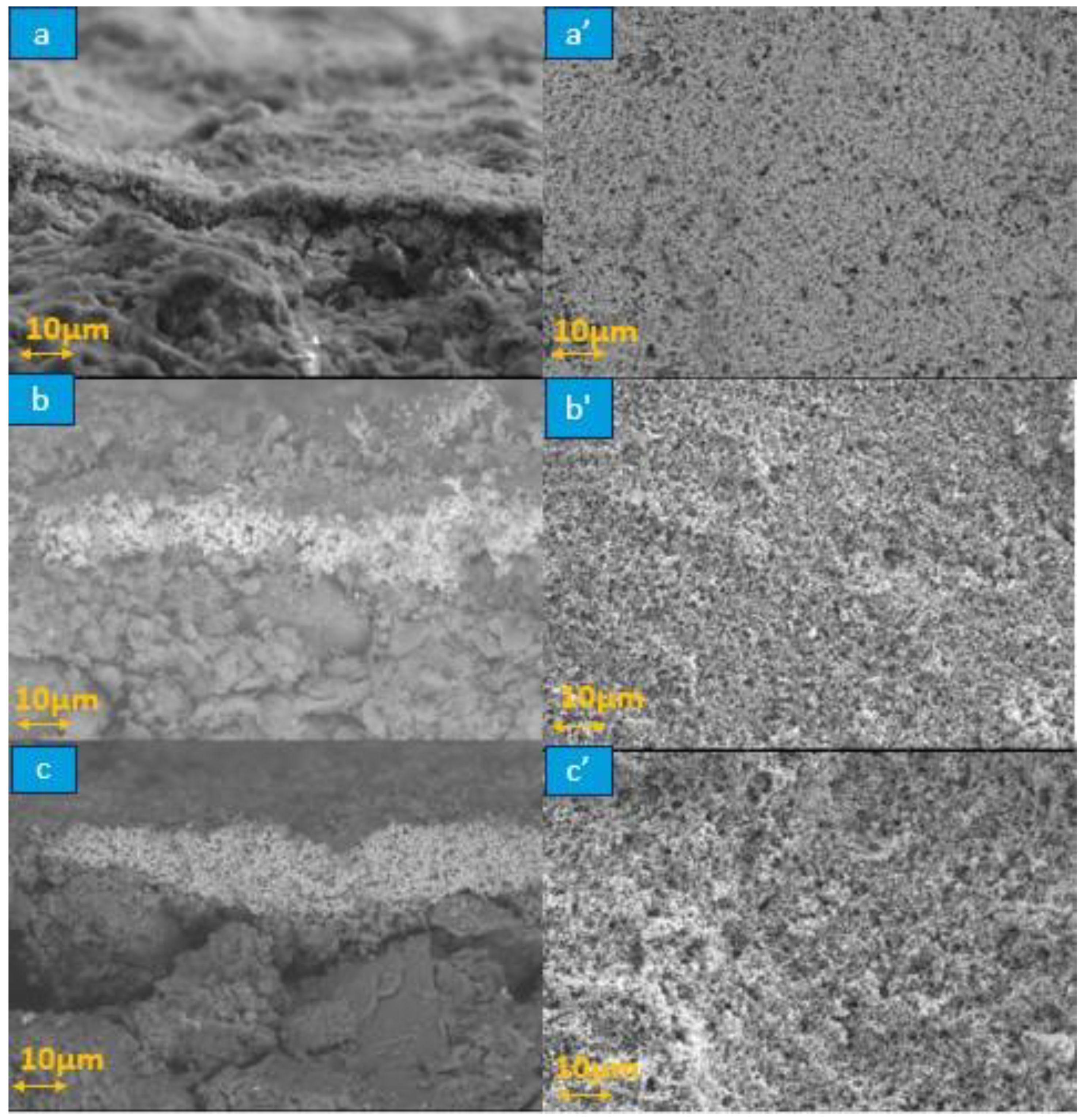
Figure 6.
EDX spectra M1(a), M2(b), and M3(c).
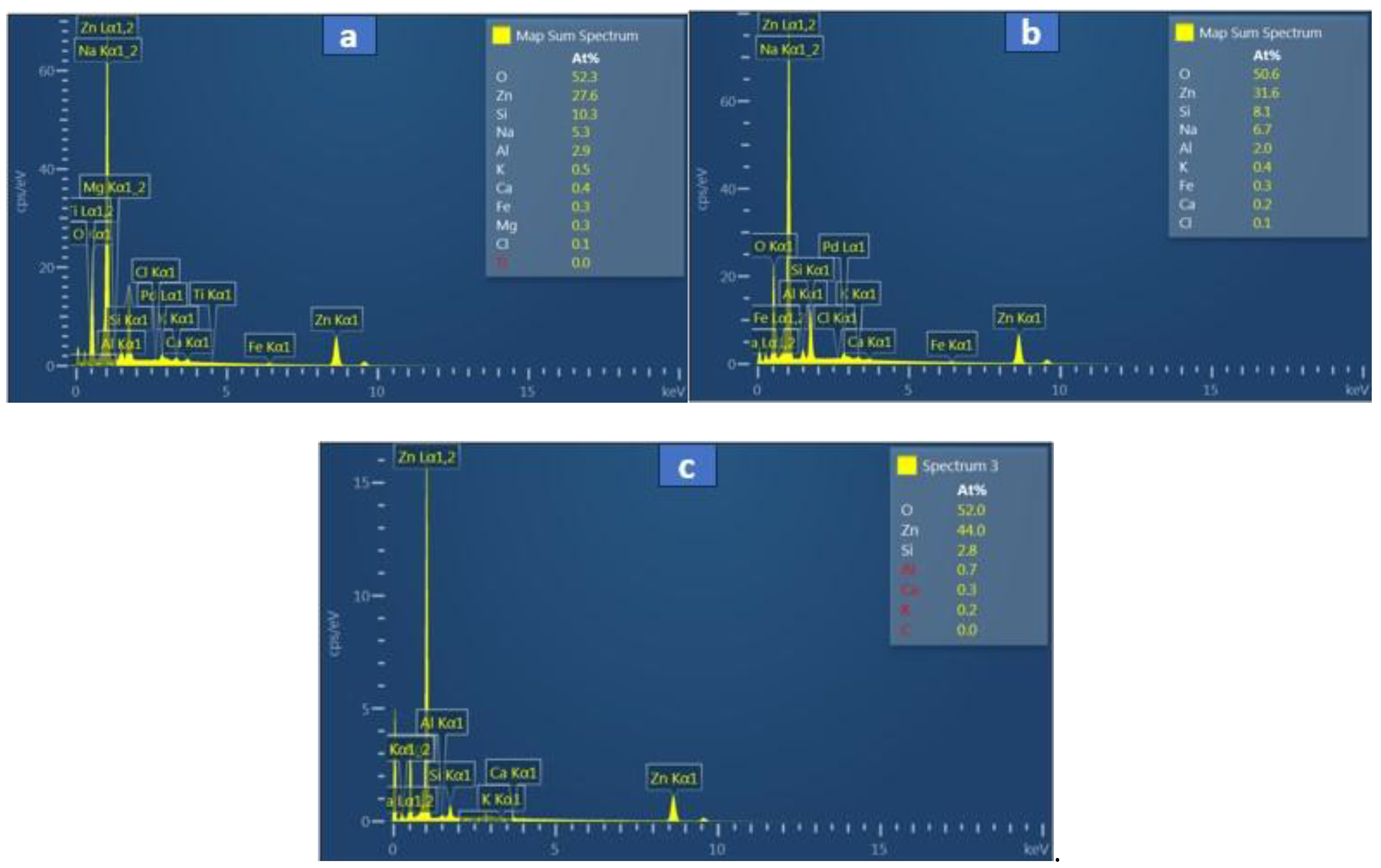
The EDX spectra from the image reveal three ZnO-coated ceramic membranes analyzed for photocatalytic wastewater treatment applications [37]. M1 displays strong Zn and O peaks with subdued substrate signals (Al, Si), indicating a uniform, thick ZnO layer [38]; [39]. M2 exhibits moderate Zn intensities alongside balanced Al/Si ratios, suggesting partial or thinner coverage from deposition methods such as spin-coating [37]. M3 exhibits lower visual peak heights but a reported 44% Zn (likely), surpassing M1 and M2 due to EDX’s normalized quantification using sensitivity factors [40]. This higher atomic percentage confirms the densest ZnO loading in M3, despite appearances, as at% accounts for matrix effects and overlaps, unlike raw intensities [39]. The green highlights in M3 may emphasize Zn-rich zones, validating superior coating. Overall, M3 offers optimal ZnO content (around 44 at%) for enhanced photocatalysis, followed by M2, then M1, ideal for organic dye degradation on zeolite supports [37]. Uniformity checks via multi-spot analysis are recommended; higher Zn correlates with better reactor performance.
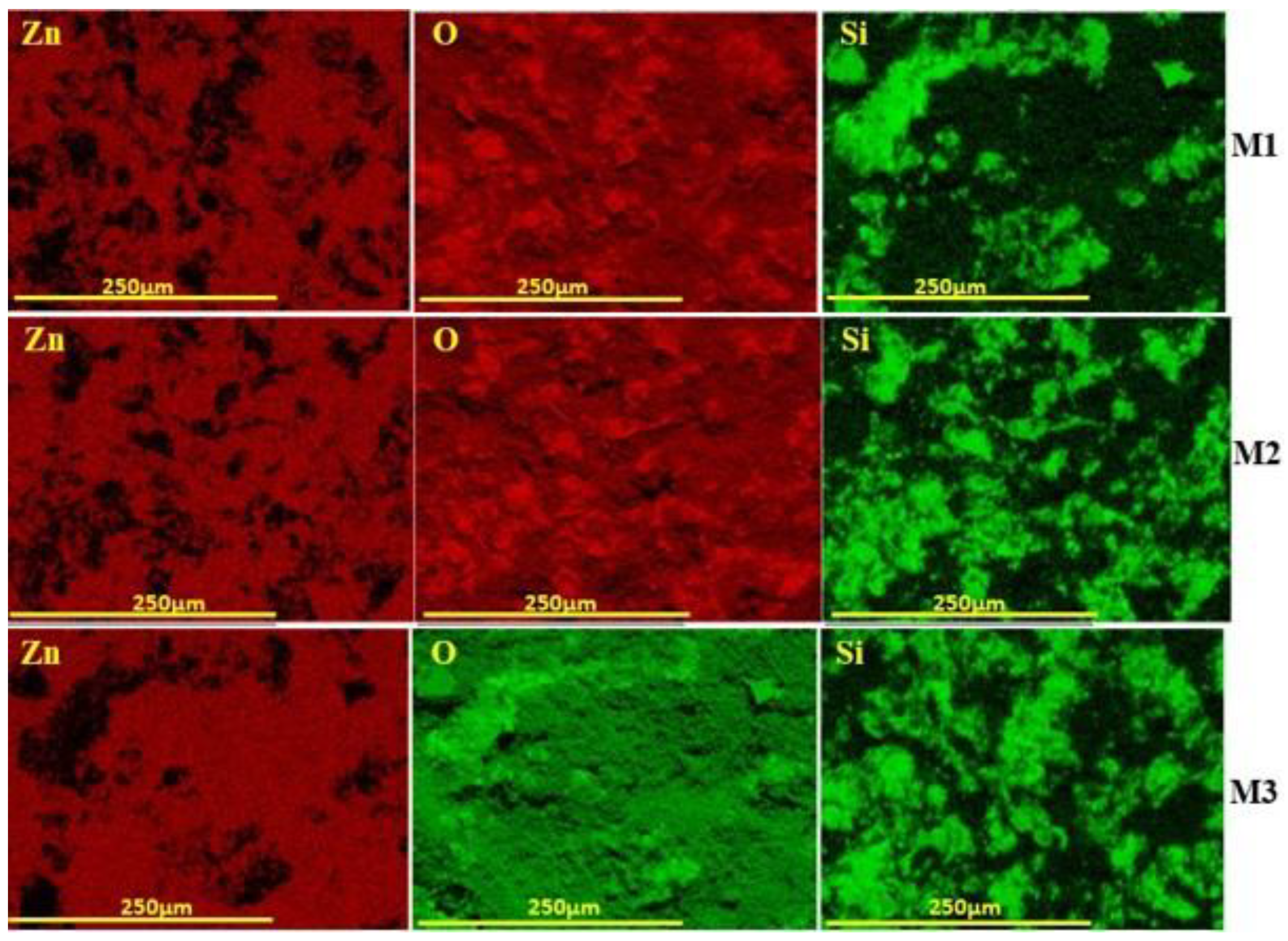
Figure 7 shows the elemental mapping of the three membranes, which highlights clear differences in ZnO coverage. M1 shows scattered Zn signals with exposed Si regions, indicating incomplete coating. M2 presents stronger and more evenly distributed Zn and O signals, suggesting better dispersion across the surface. M3 demonstrates the most uniform Zn distribution with minimal Si visibility, confirming continuous and well-adhered ZnO layers. Overall, M3 is the most effective membrane, offering superior photocatalytic potential and enhanced surface properties compared to M1 and M2.
Figure 7.
Elemental mapping of M1, M2, and M3membranes.
The porosity results followed a clear decreasing trend: the pristine membrane exhibited the highest porosity (39.2%), which progressively declined with increasing ZnO surface coating, reaching 33.6% for the M3 membrane. This reduction is attributed to partial pore coverage by the ZnO layer, which decreases the void volume and increases surface compactness.
3.1.4. Determination of Membrane Permeability
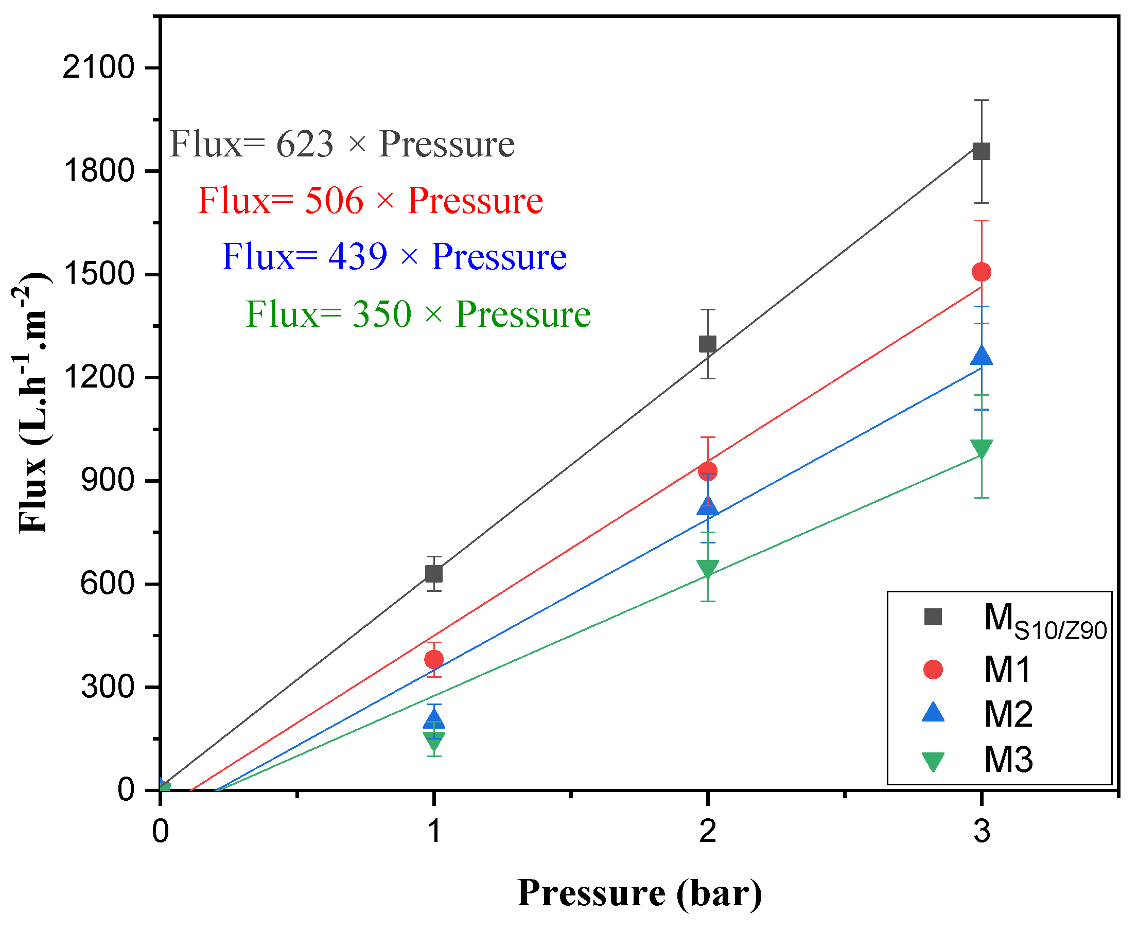
Figure 8 shows pure water permeability for an uncoated ceramic membrane (MS10/Z90) and three membranes coated with varying ZnO layers (M1: 1 layer, M2: 2 layers, M3: 3 layers). Flux decreases as the number of layers increases, with M1 exhibiting the highest permeability across all tested pressures, followed by progressively lower fluxes for M2 and M3. Each dataset follows a straight-line relationship with pressure, indicating reliable pressure-proportional flow governed by membrane resistance [39].
This reduction stems primarily from the added ZnO restricting pore openings and extending flow paths, which outweighs any gains from the material's water-attracting properties [37]; [41]. In practice, a single layer (M1) maintains strong throughput suitable for initial filtration stages, while three layers (M3) emphasize longer pollutant exposure for photocatalytic wastewater treatment, even at halved fluxes [40].
Studies on similar ZnO-modified ceramics confirm this pattern, noting that thicker or multi-layer coatings consistently lower water flux due to diminished porosity, though they enhance degradation under light [42]. For your setup, evaluating flux recovery after fouling cycles will clarify if M3's lower permeability pays off in reduced maintenance for dye removal [41].
Figure 8.
Determination of water permeability for MS10/Z90 support and M1, M2, and M3 coated membranes.
Figure 8.
Determination of water permeability for MS10/Z90 support and M1, M2, and M3 coated membranes.
3.2. Photocatalytic Activity
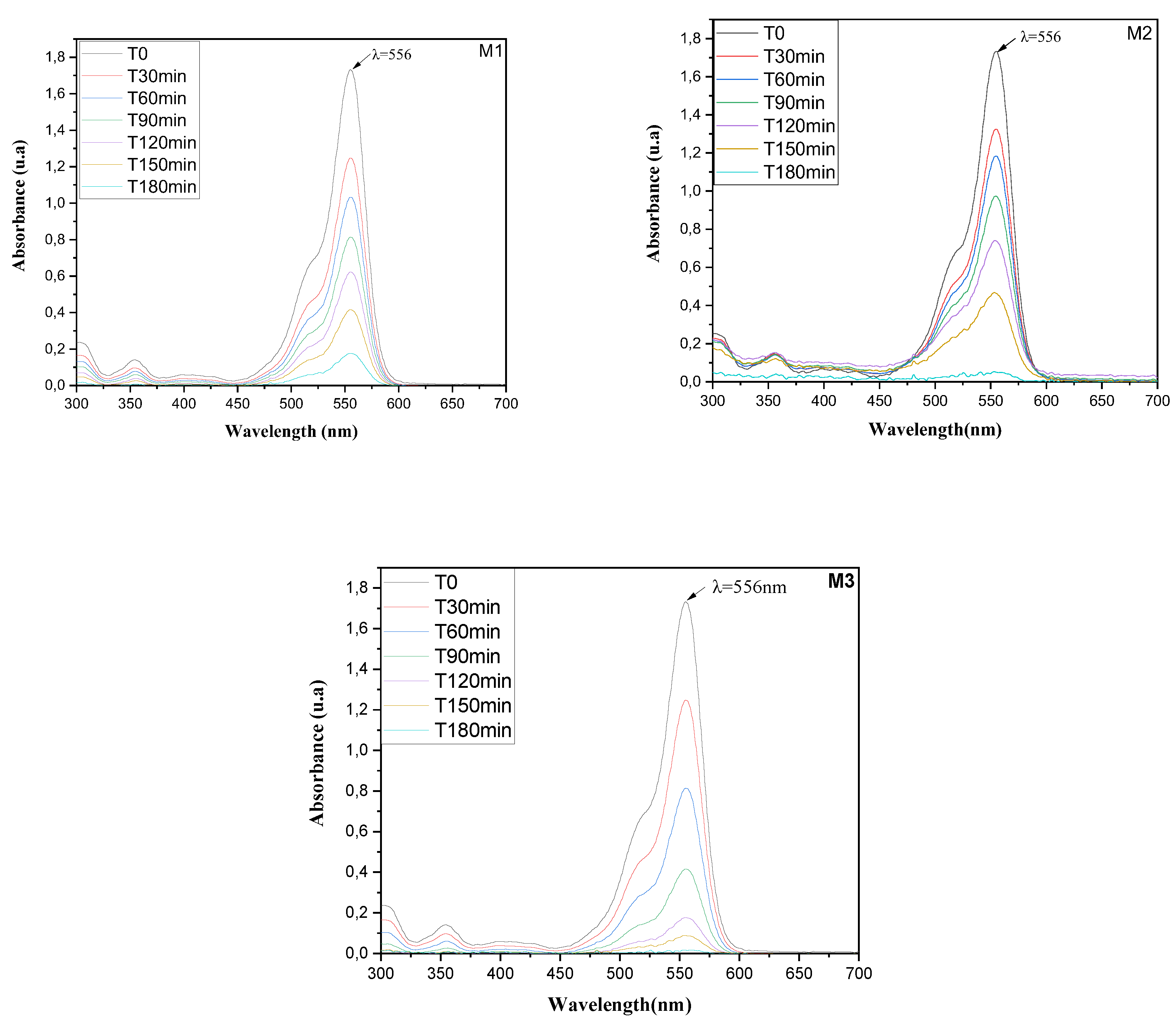
Based on the degradation kinetics monitored via the Rhodamine B absorption band at 556 nm (Figure 9), the photocatalytic performance of the membranes can be definitively ranked [43]. Membrane M1 demonstrated the least activity, with only a gradual attenuation of the peak intensity over 180 minutes, resulting in a high residual dye concentration. Membrane M2 showed moderately improved efficiency, achieving a more substantial reduction in absorbance, though significant dye persistence remained. Membrane M3 exhibited superior photocatalytic performance, characterized by a rapid and nearly complete elimination of the characteristic absorption peak, indicating extensive mineralization of the chromophore [44]. Consequently, the spectral analysis establishes a clear efficacy order: M1 < M2 < M3. This hierarchy is quantitatively supported by the comparative rates of absorbance decay and the final degree of dye degradation [45].
Figure 9.
UV–visible absorption spectra for the RhB decolorization using M1,M2, and M3 under UV irradiation. Initial RhB concentration: 10 mg.L-1.
Figure 9.
UV–visible absorption spectra for the RhB decolorization using M1,M2, and M3 under UV irradiation. Initial RhB concentration: 10 mg.L-1.
3.3. Kinetic Study
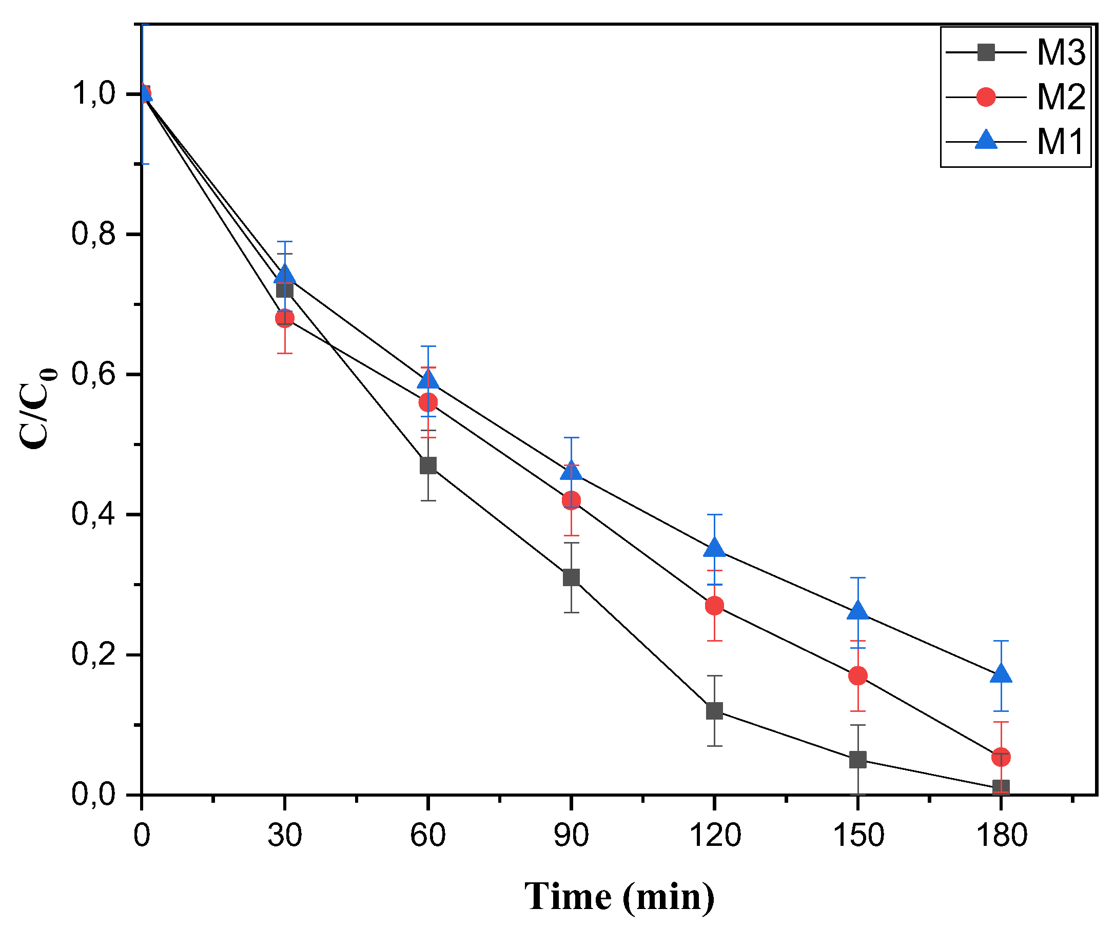
Figure 10 depicts the photocatalytic degradation kinetics, monitored over 180 minutes of UV irradiation, establish a clear performance hierarchy among the membranes [46]. The degradation profiles reveal that membrane M3 achieves the highest RhB removal, followed by M2, and then M1. This is quantitatively supported by the relative C/C₀ values at the endpoint. For M3, the C/C₀ value approaches zero, signifying nearly complete degradation of the dye (99.1%). Membrane M2 exhibits a slightly higher residual concentration, indicating strong but comparatively lower activity (94.56%). In contrast, membrane M1 demonstrates the highest C/C₀ value, confirming it possesses the least effective photocatalytic performance under these conditions (83%).
Overall, the data conclusively ranks the materials. Membrane M3 demonstrates superior efficacy, facilitating near-total RhB degradation [47]. Membrane M2 shows intermediate activity, while M1, despite achieving significant removal over the duration, exhibits the weakest performance. This order of M3 > M2 > M1 is directly derived from the rate and extent of dye decomposition observed in the degradation curves [48].
Figure 10.
Evolution of Photodegradation of RhB by M1, M2, and M3 at concentration=10 mg.L-1 versus time.
Figure 10.
Evolution of Photodegradation of RhB by M1, M2, and M3 at concentration=10 mg.L-1 versus time.
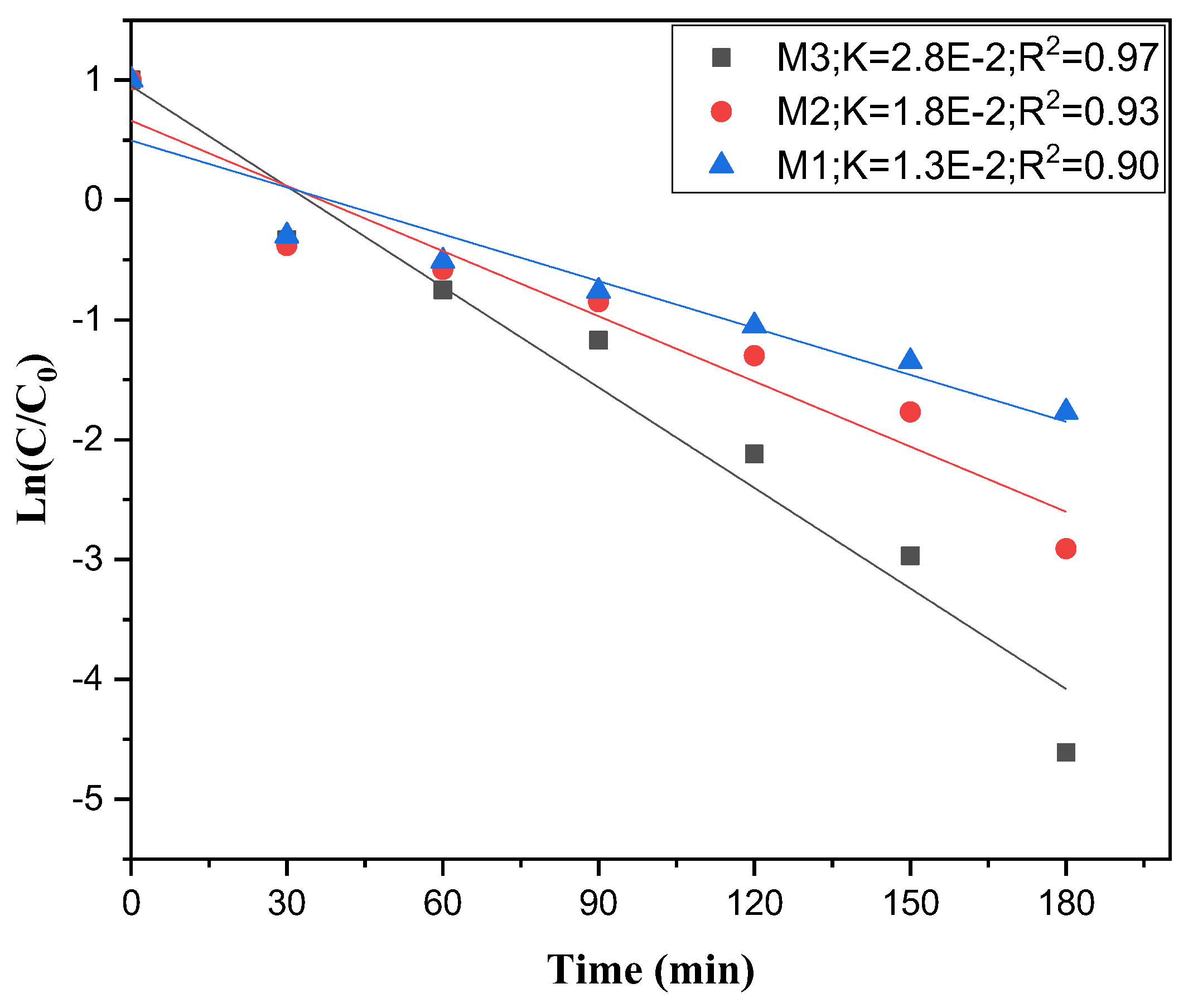
The plot of Ln(C/C0) as a function of irradiation time shows that RhB degradation over the three membranes can be well described by a pseudo-first-order kinetic model [49] .The linear evolution of Ln(C/C0) with time and the relatively high correlation coefficients (0.90-0.97) confirm that the Langmuir-Hinshelwood expression reduces to first-order behavior under the experimental conditions used [49].
Figure 11 displays the apparent rate constants, which are found to be 2.8×10⁻², 1.8×10⁻², and 1.3×10⁻² min-1 for M3, M2, and M1, respectively, indicating that M3 accelerates the disappearance of RhB much more efficiently than the other two membranes [49].This trend reflects an enhancement of the photocatalytic properties of M3, which can be attributed to its specific structural and/or compositional features (such as higher density of active sites, better dispersion of the photocatalyst, or more favorable charge separation) compared with M1 and M2.Consequently, the kinetic analysis demonstrates that the photocatalytic performance follows the order M3 > M2 > M1, in agreement with the degradation profiles obtained from the (C/C0) versus time curves.
Figure 11.
Ln(C/C0) vs. time plot of RhB conversion using M1,M2, and M3 membranes.
3.3. Self-Cleaning
Self-cleaning ability is a key requirement for photocatalytic membranes, as it directly affects their long-term performance, fouling resistance, and operational stability. In this context, the self-cleaning behavior and structural durability of the ZnO-coated membrane (M3) were evaluated after photocatalytic treatment under UV irradiation using XRD, FTIR, and SEM analyses.
XRD results (Figure 12a) show that the diffraction peaks remain at the characteristic 2θ positions of zeolite and wurtzite ZnO, including ZnO peaks around 31–37°.This indicates that the crystal phases are stable and unaffected by the photocatalytic process [50]. No noticeable shifts or disappearance of peaks are observed after use. The similar peak shapes and intensities before and after testing suggest that there is no significant loss of ZnO.Overall, the M3 coating exhibits good structural and mechanical stability during self-cleaning cycles [51].
FTIR analysis after photocatalysis shows a strong reduction or disappearance of bands related to organic contaminants (Figure 12b), such as C-H stretching vibrations at 2900-3000 cm-1 and C=O or C-O bands in the 1700-1100 cm-1region. At the same time, the characteristic framework vibrations of zeolite (Si-O-Si and Al-O-Si below 1100 cm-1) and the Zn-O bands remain unchanged [52]. This confirms that the inorganic structure is preserved during photocatalytic treatment. An increase in the broad O-H stretching band around 3200-3600cm-1 is also observed. Together, these changes indicate effective degradation of organic foulants and regeneration of a clean, hydrophilic surface [53].
Figure 12.
(a) X-ray diffraction(XRD) pattern of M3,(b) Fourier transform infrared (FTIR) spectra of M3,(c) analysis of the bottom surface of the fouled membrane.
Figure 12.
(a) X-ray diffraction(XRD) pattern of M3,(b) Fourier transform infrared (FTIR) spectra of M3,(c) analysis of the bottom surface of the fouled membrane.
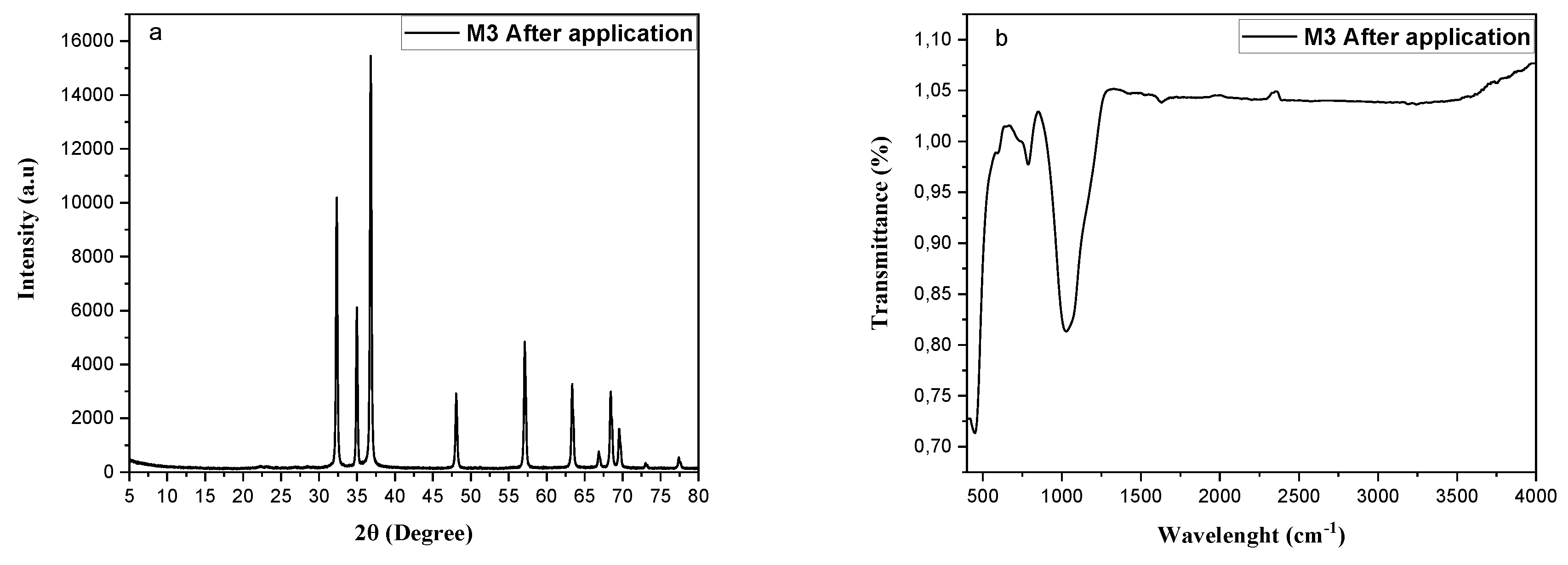
Figure 12.
(c) Analysis of the bottom surface of the fouled membrane.
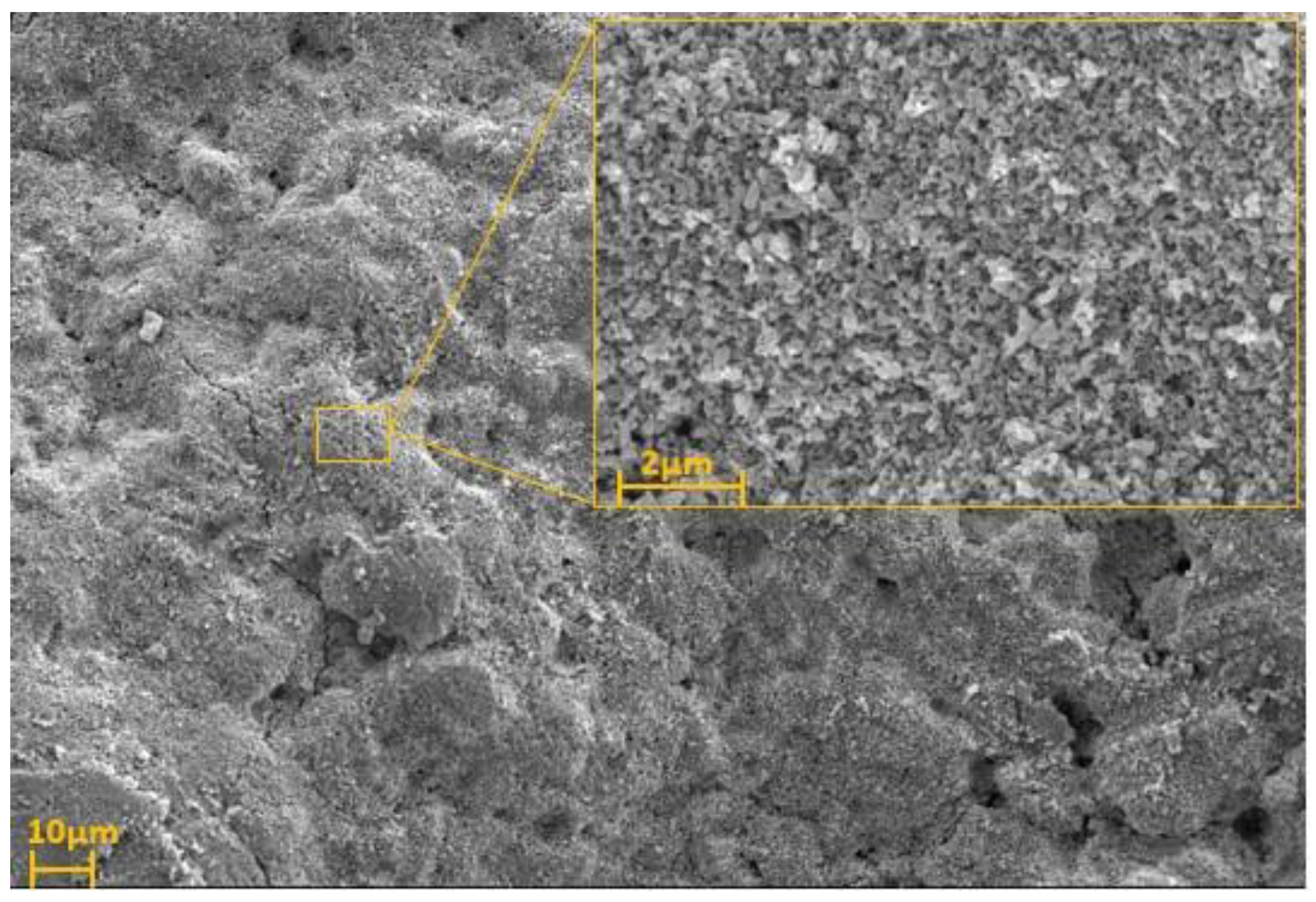
The SEM image of the ZnO-coated membrane (M3) after UV irradiation shows a bottom surface that appears fully regenerated (Figure 12(c)), indicating that the self-cleaning step was highly effective. The surface is uniformly exposed, with a continuous granular texture characteristic of the underlying support and ZnO layer, and no distinct cake layer, clusters, or deposits attributable to RhB or other foulants can be discerned [54]. This morphology suggests that photocatalytically generated oxidizing species have removed the adsorbed dye and associated organic matter from the membrane interface, leaving the pores and surface features free of observable pollutants [55].
3.5. Rhodamine B Degradation Mechanism Using M3 Membrane
ZnO coating is photocatalytically active under UV light and can degrade organic contaminants that block the pores of the Zeolite-Smectite membrane. An 18 mW UV/Visible lamp was used for the reaction. ZnO is a semiconductor with a wide band gap of 3.37 eV, absorbing mainly in the UV region ([56]. Its conduction (−0.6 eV) and valence (2.7 eV) band positions make it an effective photocatalyst. Under UV irradiation, the ZnO thin film immobilized on the ceramic membrane undergoes photoexcitation, generating electron–hole pairs:
The photogenerated holes oxidize surface-adsorbed water molecules or hydroxide ions to produce hydroxyl radicals:
while conduction-band electrons reduce dissolved oxygen to superoxide radicals:
These reactive oxygen species drive the photocatalytic degradation of Rhodamine B molecules adsorbed on the membrane surface through a sequential process of N-deethylation, chromophore disruption, and aromatic ring opening, ultimately leading to complete mineralization into CO₂ and H₂O.
The operative degradation pathways, radical scavenging experiments were performed to identify the dominant reactive oxygen species (ROS). Specific scavenger namely isopropanol (IPA) for •OH, ethylenediaminetetraacetic acid disodium salt (EDTA-2Na) for photogenerated holes (h⁺), and ascorbic acid (ASC) for superoxide radicals (O2•⁻)were introduced to isolate their individual contributions [57];[58]. A pronounced suppression of RhB degradation was observed upon the addition of these scavengers, indicating the involvement of multiple oxidative routes. As shown in Figure 13.a, the pristine ZnO catalyst under UV irradiation achieved nearly complete RhB removal (>99%). In contrast, degradation efficiencies decreased to approximately 18%, 35%, and 74% in the presence of IPA, EDTA-2Na, and ASC, respectively, underscoring their distinct inhibitory effects. This behavior can be explained by the photophysics of ZnO. UV excitation generates electron–hole pairs, with electrons (e⁻) promoted to the conduction band (CB) and holes (h⁺) remaining in the valence band (VB). The photogenerated holes either directly oxidize RhB molecules or react with surface hydroxyl groups and water to produce highly reactive •OH radicals. Concurrently, CB electrons reduce adsorbed oxygen to O2•, which may undergo further transformation into peroxides. The strong inhibition observed with IPA and EDTA-2Na confirms that •OH radicals and direct hole oxidation are the primary degradation pathways. The comparatively weaker effect of ASC suggests that superoxide radicals play only a secondary role, consistent with prior reports on ZnO-based photocatalysts [[59];[56]]. Moreover, the ceramic support contributes significantly to photocatalytic performance [60].
In summary, the scavenger assays demonstrate that RhB photodegradation over the ZnO–ceramic composite proceeds predominantly via hydroxyl radicals and direct hole oxidation, with superoxide radicals providing a minor contribution.
Figure 13.
(a)Scavenger effect on RhB degradation efficiency using M3. (IPA: Isopropanol, ASC: Ascorbic acid, EDTA-2Na: Ethylenediamine tetra-acetic acid, and SN without scavenger).
Figure 13.
(a)Scavenger effect on RhB degradation efficiency using M3. (IPA: Isopropanol, ASC: Ascorbic acid, EDTA-2Na: Ethylenediamine tetra-acetic acid, and SN without scavenger).
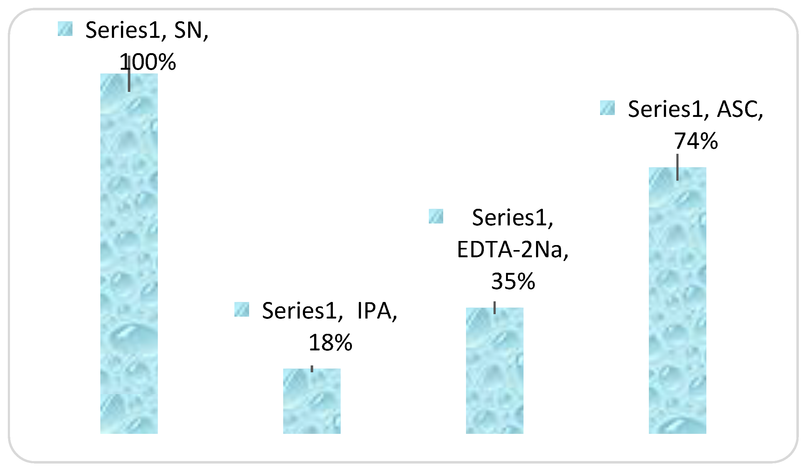
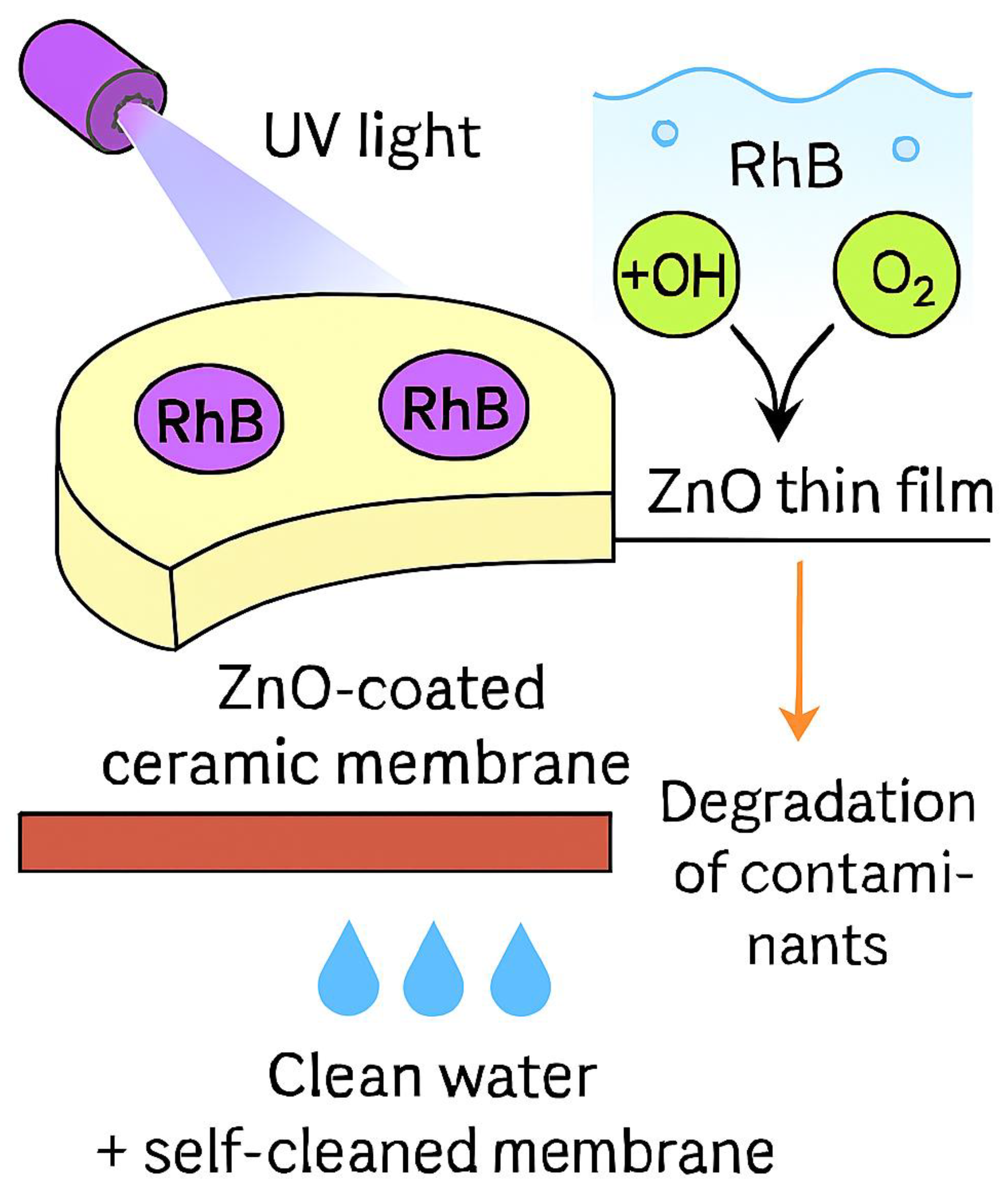
Figure 13b indicates that simultaneously, the continuous in situ generation of oxidative radicals decomposes organic foulants deposited on the membrane surface. At the same time, the enhanced hydrophilicity associated with the ZnO coating promotes the formation of a stable hydration layer, collectively imparting a self-cleaning function and mitigating membrane fouling during operation. On the whole, the photocatalytic membrane provides a clear practical advantage, as it can be readily separated from the treated water, effectively avoiding secondary pollution and reducing additional post-treatment costs.
Figure 13.
(b) proposed mechanism of photodegradation of the RhB using the M3 membrane.
4. Comparative Study
Table 4 provides a comparative evaluation of membranes, hybrid processes, photo-catalysts, and nanoparticles for the removal of Rhodamine B dye. A detailed analysis of Rhodamine B (RhB) removal efficiency across different ZnO-based membrane systems highlights the critical role of structural design, support material, and operating conditions in determining performance. For instance, Bentonite-coated perlite membranes achieved 80.1% removal at 50 ppm RhB, with moderate flux values under 4-bar pressure [61]. In contrast, hybrid systems combining ZnO photocatalysts with ceramic nanoporous membranes demonstrated superior performance, reaching 96% removal at a much higher dye concentration (500 ppm), accompanied by fluxes between 124.8 and 85.8 LMH [62]. On the other hand, ZnO-layered PTFE membranes exhibited variable efficiencies ranging from 42% to 97%, depending on dye type and [27]. Likewise, photocatalytic composites such as ZnOCu₀.₅O heterostructures achieved 73% removal at 10 ppm RB [28], while In-doped ZnO nanoparticles under UV irradiation showed comparable efficiency (73%) at 20 ppm RhB [63]. ZnO-layered porous SiC supports provided consistently high removal (91–95%) with excellent flux values exceeding 250 LMH at low operating pressure [25]. In this work, the ZnO-layered porous MS10/Z90 support developed achieved the highest efficiency, with 99.1% removal at 10 ppm RhB, confirming the effectiveness of the structured ZnO layer in enhancing photocatalytic degradation and membrane performance. Overall, this comparison demonstrates that ZnO-based membranes consistently outperform conventional supports, with removal efficiency strongly influenced by membrane architecture, dopants, and operating conditions. The present study establishes the MS10/Z90-supported ZnO membrane as a highly effective system for RhB removal, aligning with and surpassing reported performances in the literature.
5. Conclusions
This work demonstrates the successful fabrication of a low-cost ceramic photocatalytic membrane by depositing ZnO onto a zeolite/smectite support using the spin-coating technique. Optimization of the active layer showed that the membrane M3, containing three ZnO layers (4 wt%), exhibits a homogeneous, compact, and defect-free morphology. The M3 membrane achieved an excellent Rhodamine B degradation efficiency of 99.1% under UV irradiation, following pseudo-first-order kinetics, due to the increased density of active sites and efficient charge separation. Although the addition of ZnO layers led to a reduction in water permeability, this trade-off favors longer pollutant-catalyst contact time and improved degradation performance. Importantly, the membrane displayed an intrinsic self-cleaning ability, with effective removal of organic foulants under UV light and full regeneration of its hydrophilic surface. Structural analyses confirmed the stability of both the ZnO (wurtzite) phase and the ceramic support after repeated use. Overall, this bifunctional membrane integrates size-selective filtration and photocatalytic degradation, offering a durable and sustainable solution for mitigating organic fouling in textile wastewater treatment.
Funding
This work has received funding from PRIMA Foundation. Grant Agreement number: [2024] [TRUST]-Call 2020 Sect. 1 Water IA.
Data availability
The data relevant to this work are presented in the manuscript.
References
- Espinosa, M.; Afonso, C.; Saraiva, B.; Vione, D.; Fernandes, A. Textile Wastewater Treatment by Membrane and Electrooxidation Processes: A Critical Review. Clean Technol. 2026, 8, 9. [Google Scholar] [CrossRef]
- Khan, W.U.; Ahmed, S.; Dhoble, Y.; Madhav, S. A Critical Review of Hazardous Waste Generation from Textile Industries and Associated Ecological Impacts. J. Indian Chem. Soc. 2023, 100, 100829. [Google Scholar] [CrossRef]
- Aouay, F.; Attia, A.; Dammak, L.; Ben Amar, R.; Deratani, A. Activated Carbon Prepared from Waste Coffee Grounds: Characterization and Adsorption Properties of Dyes. Materials 2024, 17, 3078. [Google Scholar] [CrossRef]
- Oladimeji, T.E.; Oyedemi, M.; Emetere, M.E.; Agboola, O.; Adeoye, J.B.; Odunlami, O.A. Review on the Impact of Heavy Metals from Industrial Wastewater Effluent and Removal Technologies. Heliyon 2024, 10, e40370. [Google Scholar] [CrossRef]
- Imam, S.; Babamale, H. A Short Review on the Removal of Rhodamine B Dye Using Agricultural Waste-Based Adsorbents. Asian J. Chem. Sci. 2020, 25–37. [Google Scholar] [CrossRef]
- Postai, D.L.; Demarchi, C.A.; Zanatta, F.; Melo, D.C.C.; Rodrigues, C.A. Adsorption of Rhodamine B and Methylene Blue Dyes Using Waste of Seeds of Aleurites Moluccana, a Low Cost Adsorbent. Alex. Eng. J. 2016, 55, 1713–1723. [Google Scholar] [CrossRef]
- Saadi, A.S.; Slimane Ben Ali, D.; Bousba, S. Utilization of a Biosorbent Derived from Plant Residues for the Treatment of Water Contaminated with Rhodamine B: Preparation and Characterization. RSC Adv. 2025, 15, 43038–43052. [Google Scholar] [CrossRef] [PubMed]
- ATTIA, A.; Ahmed, A.B.; Bhattacharyya, S.; Cozzolino, V.; Algieri, C.; Chakraborty, S.; AMAR, R.B. PES/Clay Mixed Matrix Membranes for Efficient Removal of Recalcitrant Chloramphenicol: Experimental and DFT Study. Chem. Eng. J. 2026, 527, 172025. [Google Scholar] [CrossRef]
- Foorginezhad, S.; Zerafat, M.M.; Ismail, A.F.; Goh, P.S. Emerging Membrane Technologies for Sustainable Water Treatment: A Review on Recent Advances. Environ. Sci. Adv. 2025, 4, 530–570. [Google Scholar] [CrossRef]
- Guo, W.; Ngo, H.-H.; Li, J. A Mini-Review on Membrane Fouling. Bioresour. Technol. 2012, 122, 27–34. [Google Scholar] [CrossRef]
- Qi, L.; Li, S.; Duan, L.; Hermanowicz, S.; Ng, H. A Review on Membrane Modification Techniques for Membrane Fouling Control: Mechanisms and Membrane Preparation. Crit. Rev. Environ. Sci. Technol. 2025, 55, 1455–1478. [Google Scholar] [CrossRef]
- Bahrouni, J.; Aloulou, H.; Attia, A.; Dammak, L.; Amar, R.B. Surface Modification of a Zeolite Microfiltration Membrane: Characterization and Application to the Treatment of Colored and Oily Wastewaters. Chem. Afr. 2024, 7, 4513–4527. [Google Scholar] [CrossRef]
- Sak, G.; Taşar, Ş.; Dursun, G. Organic Pollutant Degradation Through Photocatalysis: Progress, Challenges, and Sustainable Solutions (Mini Review). Appl. Sci. 2026, 16, 204. [Google Scholar] [CrossRef]
- Karim, N.; Kyawoo, T.; Jiang, C.; Ahmed, S.; Tian, W.; Li, H.; Feng, Y. Fenton-like Degradation of Methylene Blue on Attapulgite Clay Composite by Loading of Iron–Oxide: Eco-Friendly Preparation and Its Catalytic Activity. Materials 2024, 17, 2615. [Google Scholar] [CrossRef]
- Zhang, D.; Yang, X.; Wang, T.; Wang, H.; Cao, S.; Shi, H. Efficient Adsorption of Typical Antibiotics by Petroleum Coke-Based Ultra-Large Surface Porous Carbon Materials: Mechanism and Cost Analysis. Chem. Eng. Res. Des. 2025, 222, 557–572. [Google Scholar] [CrossRef]
- Ibrahim, I.; Elseman, A.M.; Sadek, H.; Eliwa, E.M.; Abusaif, M.S.; Kyriakos, P.; Belessiotis, G.V.; Mudgal, M.M.; Abdelbasir, S.M.; Elsayed, M.H.; et al. Membrane-Based Photocatalytic and Electrocatalytic Systems: A Review. Catalysts 2025, 15, 528. [Google Scholar] [CrossRef]
- Baig, U.; Al-Kuhaili, M.F.; Dastageer, M.A. Photo-Responsive Zinc Oxide-Coated Alumina Ceramic Membrane with Super-Wettable and Self-Cleaning Features Fabricated by Single Step RF Magnetron Sputtering for Oily Water Treatment. Process Saf. Environ. Prot. 2023, 175, 541–553. [Google Scholar] [CrossRef]
- Kuang, C.; Li, Y.; Liu, D.; Li, Y.; Sun, D.; Chen, J.; Donghai, D.; Xiao, G. An Al2O3@ZnO Membrane for Oil-in-Water Emulsion Separation with Photocatalytic Regeneration Prepared via a Simple Deposition Route. J. Water Process Eng. 2024, 67, 106254. [Google Scholar] [CrossRef]
- Wei, J.; Nian, P.; Wang, Y.; Wang, X.; Wang, Y.; Xu, N.; Wei, Y. Preparation of Superhydrophobic-Superoleophilic ZnO nanoflower@SiC Composite Ceramic Membranes for Water-in-Oil Emulsion Separation. Sep. Purif. Technol. 2022, 292, 121002. [Google Scholar] [CrossRef]
- Huang, A. Fabrication of Zinc Oxide Nanostructure Coated Membranes for Efficient Oil/Water Separation. J. Membr. Sci. 2018. [Google Scholar] [CrossRef]
- Molinari, R.; Pietro, A.; Szymański, K.; Darowna, D.; Mozia, S. Photocatalytic Membrane Reactors for Wastewater Treatment; 2020; pp. 83–116. ISBN 978-0-12-816823-3. [Google Scholar]
- Muscetta, M.; Ganguly, P.; Clarizia, L. Solar-Powered Photocatalysis in Water Purification: Applications and Commercialization Challenges. J. Environ. Chem. Eng. 2024, 12, 113073. [Google Scholar] [CrossRef]
- Rakcho, Y.; Naboulsi, A.; Mansouri, S.; Mouiya, M.; Sehaqui, H.; Bouazizi, A.; Abouliatim, Y.; Benhammou, A.; Abourriche, A.; Alami, J. Sustainable Valorization of Food Waste into a Pore-Forming Agent for Ceramic Membrane Production: Experimental and DFT Studies on Methylene Blue Dye Removal. Sustain. Mater. Technol. 2024, 42, e01181. [Google Scholar] [CrossRef]
- Khmiri, Y.; Attia, A.; Aloulou, H.; Dammak, L.; Baklouti, L.; Ben Amar, R. Preparation and Characterization of New and Low-Cost Ceramic Flat Membranes Based on Zeolite-Clay for the Removal of Indigo Blue Dye Molecules. Membranes 2023, 13, 865. [Google Scholar] [CrossRef]
- Santra, N.; Tudu, M.; Chatterjee, S.; Samanta, A.; Kayal, N. Preparation of ZnO Nanostructures in SiC Ceramic Membrane for Removal of Dyes from Water and Its Antibacterial Activity. Water. Air. Soil Pollut. 2025, 236, 700. [Google Scholar] [CrossRef]
- Khmiri, Y.; Attia, A.; Elboughdiri, N.; Ghernaout, D.; Charcosset, C.; Dammak, L.; Amar, R.B. Preparing Sustainable Membranes Made From Zeolite–Smectite for Treating Textile Wastewater and Pulp Industry Wastewater. ChemistrySelect 2024, 9. [Google Scholar] [CrossRef]
- Xiong, Z.; Cao, J.; Yang, D.; Lai, B.; Yang, P. Coagulation-Flocculation as Pre-Treatment for Micro-Scale Fe/Cu/O3 Process (CF-mFe/Cu/O3) Treatment of the Coating Wastewater from Automobile Manufacturing. Chemosphere 2017, 166, 343–351. [Google Scholar] [CrossRef]
- Nandi, P.; Das, D. ZnO-CuxO Heterostructure Photocatalyst for Efficient Dye Degradation. J. Phys. Chem. Solids 2020, 143, 109463. [Google Scholar] [CrossRef]
- Kayani, Z.; Iqbal, M.; Riaz, S.; Zia, R.; Naseem, S. Fabrication and Properties of Zinc Oxide Thin Film Prepared by Sol-Gel Dip Coating Method. Mater. Sci.-Pol. 2014, 33. [Google Scholar] [CrossRef]
- Uğur, Ş.S.; Sarıışık, M.; Aktaş, A.H.; Uçar, M.Ç.; Erden, E. Modifying of Cotton Fabric Surface with Nano-ZnO Multilayer Films by Layer-by-Layer Deposition Method. Nanoscale Res. Lett. 2010, 5, 1204. [Google Scholar] [CrossRef]
- Zerdali, M.; Hamzaoui, S.; Teherani, F.H.; Rogers, D. Growth of ZnO Thin Film on SiO2/Si Substrate by Pulsed Laser Deposition and Study of Their Physical Properties. Mater. Lett. 2006, 60, 504–508. [Google Scholar] [CrossRef]
- Oliaee, J.; Dehghany, M.; McKellar, A.; Moazzen-Ahmadi, N. High Resolution Infrared Spectroscopy of Carbon Dioxide Clusters up to (CO2)(13). J. Chem. Phys. 2011, 135, 044315. [Google Scholar] [CrossRef] [PubMed]
- Na, J.-S.; Gong, B.; Scarel, G.; Parsons, G.N. Surface Polarity Shielding and Hierarchical ZnO Nano-Architectures Produced Using Sequential Hydrothermal Crystal Synthesis and Thin Film Atomic Layer Deposition. ACS Nano 2009, 3, 3191–3199. [Google Scholar] [CrossRef]
- O’Brien, S.; Nolan, M.; Çopuroğlu, M.; Hamilton, J.; Povey, I.; Pereira, L.; Martins, R.; Fortunato, E.; Pemble, M. Zinc Oxide Thin Films: Characterization and Potential Applications. Thin Solid Films 2010, 518, 4515–4519. [Google Scholar] [CrossRef]
- Venables, J. Introduction to Surface and Thin Film Processes. Introd. Surf. Thin Film Process. John Venables Pp 392 ISBN 0521785006 Camb. UK Camb. Univ. Press Novemb. 2000 2000, 145–146. [Google Scholar] [CrossRef]
- Özgür, Ü.; Alivov, Y.; Liu, C.; Teke, A.; Reshchikov, M.; Dogan, S.; Avrutin, V.; Cho, S.-J.; Morkoç, H. A Comprehensive Review of ZnO Materials and Devices. J. Appl. Phys. 2005, 98, 041301–041301. [Google Scholar] [CrossRef]
- Salih, A.; Irvine, C.; Matar, F.; Aditya, L.; Nghiem, L.; Ton, C. Photocatalytic Self-Cleansing ZnO-Coated Ceramic Membranes for Preconcentrating Microalgae. J. Membr. Sci. 2025, 718, 123700. [Google Scholar] [CrossRef]
- Roshani, R.; Ardeshiri, F.; Peyravi, M.; Jahanshahi, M. Highly Permeable PVDF Membrane with PS/ZnO Nanocomposite Incorporated for Distillation Process. RSC Adv 2018, 8, 23499–23515. [Google Scholar] [CrossRef]
- Shaban, M.; Abdallah, S.; Khalek, A.A. Characterization and Photocatalytic Properties of Cotton Fibers Modified with ZnO Nanoparticles Using Sol–Gel Spin Coating Technique. Beni-Suef Univ. J. Basic Appl. Sci. 2016, 5, 277–283. [Google Scholar] [CrossRef]
- Alrebdi, T.A.; Ahmed, H.A.; Alkallas, F.H.; Pashameah, R.A.; Alrefaee, S.H.; Alsubhe, E.; Mostafa, A.M.; Mwafy, E.A. Ag/ZnO Thin Film Nanocomposite Membrane Prepared by Laser-Assisted Method for Catalytic Degradation of 4-Nitrophenol. Membranes 2022, 12, 732. [Google Scholar] [CrossRef]
- Salih, A.K.; Aditya, L.; Matar, F.; Nghiem, L.D.; Ton-That, C. Improved Flux and Anti-Fouling Performance of a Photocatalytic ZnO Membrane on Porous Stainless Steel Substrate for Microalgae Harvesting. J. Membr. Sci. 2024, 694, 122405. [Google Scholar] [CrossRef]
- Sawunyama, L.; Oyewo, O.A.; Makgato, S.S.; Bopape, M.F.; Onwudiwe, D.C. TiO2–ZnO Functionalized Low-Cost Ceramic Membranes from Coal Fly Ash for the Removal of Tetracycline from Water under Visible Light. Discov. Nano 2025, 20, 1. [Google Scholar] [CrossRef]
- Mukherjee, S.; Ghati, A.; Paul, G. An Ultraviolet–Visible Spectrophotometric Approach to Establish a Method for Determining the Presence of Rhodamine B in Food Articles. ACS Food Sci. Technol. 2021, 1. [Google Scholar] [CrossRef]
- Hu, X.; Mohamood, T.; Ma, W.; Chen, C.; Zhao, J. Oxidative Decomposition of Rhodamine B Dye in the Presence of VO2+ and/or Pt(IV) under Visible Light Irradiation: N-Deethylation, Chromophore Cleavage, and Mineralization. J. Phys. Chem. B 2006, 110, 26012–26018. [Google Scholar] [CrossRef]
- Percivalle, N.M.; Carofiglio, M.; Hernández, S.; Cauda, V. Ultra-Fast Photocatalytic Degradation of Rhodamine B Exploiting Oleate-Stabilized Zinc Oxide Nanoparticles. Discov. Nano 2024, 19, 126. [Google Scholar] [CrossRef] [PubMed]
- Herrmann, J.-M. Photocatalysis Fundamentals Revisited to Avoid Several Misconceptions. Appl. Catal. B Environ. 2010, 99, 461–468. [Google Scholar] [CrossRef]
- Feng, D.-M.; Zhu, Y.-P.; Chen, P.; Ma, T.-Y. Recent Advances in Transition-Metal-Mediated Electrocatalytic CO2 Reduction: From Homogeneous to Heterogeneous Systems. Catalysts 2017, 7, 373. [Google Scholar] [CrossRef]
- Garcia, J.; Iborra-Clar, M.I.; Miranda, M.-I.; Van der Bruggen, B. Comparison between Hydrophilic and Hydrophobic Metal Nanoparticles on the Phase Separation Phenomena during Formation of Asymmetric Polyethersulphone Membranes. J. Membr. Sci. 2015, 493, 709. [Google Scholar] [CrossRef]
- Chang, N.; Liu, J.; Ji, Y.; Liu, J.; Chen, Y. Kinetic Study of Rhodamine B Degradation of Electro-Catalysis by TiO2/Activated Semi-Coke Composite as Tiny Electrode. J. Sol-Gel Sci. Technol. 2023, 106, 1–15. [Google Scholar] [CrossRef]
- Binazadeh, M.; Rasouli, J.; Sabbaghi, S.; Mousavi, S.M.; Hashemi, S.A.; Lai, C.W. An Overview of Photocatalytic Membrane Degradation Development. Materials 2023, 16, 3526. [Google Scholar] [CrossRef]
- Sarabyar, S.; Farahbakhsh, A.; Tahmasebi, H.; Vaziri, B.; Khosroyar, S. Enhancing Photocatalytic Degradation of Beta-Blocker Drugs Using TiO2 NPs/Zeolite and ZnO NPs/Zeolite as Photocatalysts: Optimization and Kinetic Investigations. Sci. Rep. 2024, 14. [Google Scholar] [CrossRef]
- Kabadayi, O.; Altintig, E.; Ballai, G. Zeolite Supported Zinc Oxide Nanoparticles Composite: Synthesis, Characterization, and Photocatalytic Activity for Methylene Blue Dye Degradation. Desalination Water Treat. 2024, 319, 100433. [Google Scholar] [CrossRef]
- Cahyanti, R.; Sumari, S.; Fajaroh, F.; Asrori, M.R.; Prakasa, Y. Fe-TiO2/Zeolite H-A Photocatalyst for Degradation of Waste Dye (Methylene Blue) under UV Irradiation. AIMS Mater. Sci. 2023, 10, 40–54. [Google Scholar] [CrossRef]
- Park, K.-H.; Sun, P.-F.; Kang, E.H.; Han, G.D.; Kim, B.J.; Jang, Y.; Lee, S.-H.; Shim, J.H.; Park, H.-D. Photocatalytic Anti-Biofouling Performance of Nanoporous Ceramic Membranes Treated by Atomic Layer Deposited ZnO. Sep. Purif. Technol. 2021, 272, 118935. [Google Scholar] [CrossRef]
- Mousa, S.A.; Abdallah, H.; Khairy, S.A. Low-Cost Photocatalytic Membrane Modified with Green Heterojunction TiO2/ZnO Nanoparticles Prepared from Waste. Sci. Rep. 2023, 13, 22150. [Google Scholar] [CrossRef]
- Khmiri, Y.; Attia, A.; Jallouli, N.; Chabanon, E.; Charcosset, C.; Mahouche-Chergui, S.; Dammak, L.; Algieri, C.; Chakraborty, S.; Amar, R.B. Synthesis of a Cost-Effective ZnO/Zeolite Photocatalyst for Paracetamol Removal. Emergent Mater. 2025. [Google Scholar] [CrossRef]
- Khalid, A.; Ahmad, P.; Memon, R.; Gado, L.F.; Khandaker, M.U.; Almukhlifi, H.A.; Modafer, Y.; Bashir, N.; Abida, O.; Alshammari, F.A.; et al. Structural, Optical, and Renewable Energy-Assisted Photocatalytic Dye Degradation Studies of ZnO, CuZnO, and CoZnO Nanostructures for Wastewater Treatment. Separations 2023, 10, 184. [Google Scholar] [CrossRef]
- Patil, S.P.; Shrivastava, V.S.; Sonawane, G.H. Photocatalytic Degradation of Rhodamine 6G Using ZnO-Montmorillonite Nanocomposite: A Kinetic Approach. Desalination Water Treat. 2015, 54, 374–381. [Google Scholar] [CrossRef]
- Attia, A.; Elboughdiri, N.; Ghernaout, D.; Carbonnier, B.; Amar, R.B.; Mahouche-Chergui, S. Enhancing the Generation and Stabilization of ZnO Nanoparticles on Modified Clay with Polyethylenimine to Improve the Photodegradation of Dyes in Textile Wastewater. J. Water Process Eng. 2025, 73, 107711. [Google Scholar] [CrossRef]
- Haounati, R.; Ighnih, H.; Malekshah, R.E.; Alahiane, S.; Alakhras, F.; Alabbad, E.; Alghamdi, H.; Ouachtak, H.; Addi, A.A.; Jada, A. Exploring ZnO/Montmorillonite Photocatalysts for the Removal of Hazardous RhB Dye: A Combined Study Using Molecular Dynamics Simulations and Experiments. Mater. Today Commun. 2023, 35, 105915. [Google Scholar] [CrossRef]
- Saja, S.; Bouazizi, A.; Achiou, B.; Ouaddari, H.; Karim, A.; Ouammou, M.; Aaddane, A.; Bennazha, J.; Younssi, S.A. Fabrication of Low-Cost Ceramic Ultrafiltration Membrane Made from Bentonite Clay and Its Application for Soluble Dyes Removal. J. Eur. Ceram. Soc. 2020, 40, 2453–2462. [Google Scholar] [CrossRef]
- Yadav, D.; Kishore, K.; Bethi, B.; Sonawane, S.; Bhagawan, D. ZnO Nanophotocatalysts Coupled with Ceramic Membrane Method for Treatment of Rhodamine-B Dye Waste Water. Environ. Dev. Sustain. 2018, 20. [Google Scholar] [CrossRef]
- Pradeev Raj, K.; Sadaiyandi, K.; Kennedy, A.; Sagadevan, S. Photocatalytic and Antibacterial Studies of Indium-Doped ZnO Nanoparticles Synthesized by Co-Precipitation Technique. J. Mater. Sci. Mater. Electron. 2017, 28, 19025–19037. [Google Scholar] [CrossRef]

Table 1.
The characteristics of RhB.
| Dye | Molecular Formula |
Molecular Weight (g.mol-1) |
Wavelength (λmax) (nm) |
Charge | Chemical structure |
|
RhB |
C28H31N2O3Cl |
479.01 |
556 |
Cationic |
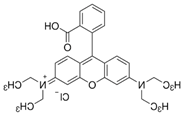 |
Table 2.
Ceramic support characteristics.
| Parameters | Values |
| Water permeability (L.h-1.m-2.bar-1) | 623 |
| Mechanical strength (MPa) | 23 |
| Average pore size (µm) | 0.98 |
| Permeability (%) | 39.2 |
Table 3.
Prepared Membrane and coating Layers.
| Membrane | Coating layers |
|---|---|
| M1 | 1 |
| M2 | 2 |
| M3 | 3 |
Table 4.
Comparison of Rhodamine B Removal Efficiency Using ZnO-Structured Membranes.
| Structured membrane | RB concentration |
Performances | Reference |
| Bentonite coated perlite mem- brane |
50 ppm | -Dye removal Efficiency 80.1% Permeability 21 L.m-2.h-1.bar-1 |
[61] |
| ZnO photocatalyst coupled with ceramic Nanoporous membrane (hybrid system) |
500 ppm | Dye removal Efficiency 96 % water flux Permeability 31-21 L.m-2.h-1.bar-1 |
[62] |
| ZnO layered polytetrafluorethylene membrane |
10-100 ppm | Removal Efficiency 42-97 % |
[27] |
| ZnO-Cu0.5 O hetro composite structure (photocatalyst) |
10 ppm | Removal Efficiency 73 % |
[28] |
| 6% In-doped ZnO nano par- ticles (under UV radiation) ––– RB |
20 ppm | -Removal Efficiency 73 % |
[63] |
| ZnO layered porous SiC support |
4-50 ppm | Removal Efficiency 91-95% Permeability 306-205 L.m-2.h-1.bar-1 |
[25] |
| ZnO layered porous support MS10/Z90 |
10 ppm | Removal Efficiency 99.1% |
This work |
Disclaimer/Publisher’s Note: The statements, opinions and data contained in all publications are solely those of the individual author(s) and contributor(s) and not of MDPI and/or the editor(s). MDPI and/or the editor(s) disclaim responsibility for any injury to people or property resulting from any ideas, methods, instructions or products referred to in the content. |
© 2026 by the authors. Licensee MDPI, Basel, Switzerland. This article is an open access article distributed under the terms and conditions of the Creative Commons Attribution (CC BY) license (http://creativecommons.org/licenses/by/4.0/).
Copyright: This open access article is published under a Creative Commons CC BY 4.0 license, which permit the free download, distribution, and reuse, provided that the author and preprint are cited in any reuse.


