
Submitted:
10 February 2026
Posted:
12 February 2026
You are already at the latest version
Abstract
The incorporation of recycled metallurgical slags into refractory materials constitutes a promising approach to enhancing sustainability in the refractory industry. This study investigates the effect of vanadium-bearing slag aggregates as partial replace-ments for tabular alumina in castables and compares their behaviour with high-alumina and bauxite-based castables. Two vanadium-bearing slags with differ-ent mineralogical compositions were introduced in the 1-3 mm aggregate fraction with substitution up to 25 wt.%. Their effects on microstructure, thermo-mechanical performance and corrosion resistance were evaluated. The introduction of vanadi-um-bearing slag significantly alters the microstructure of the castables, affecting their performance. Both slags displayed grains with higher porosity, microcracking, and heterogeneity compared with tabular alumina, but show similarities with bauxite grains. Slag 1, enriched in calcium aluminate phases, provides limited mechanical strength but improved corrosion resistance due to improved bonding with the matrix. Slag 2, containing a higher spinel content, enhances mechanical strength, showing behaviour comparable to bauxite-based castables, particularly at 10 wt.% replacement. Vanadium is mainly present in metallic form and as Mg(Al,V)2O4 spinel in both slags. Upon firing, vanadium migrates toward grain boundaries and reacts with surround-ing calcium aluminate phases to be incorporated in Ca(Al,V)2O4 and Ca(Al,V)4O7, while the spinel phase remains stable.
Keywords:
metallurgical slag
; refractories
; valorization
; aggregates
; microstructure
; thermo-mechanical properties
1. Introduction
The current environmental and economic landscape of the refractory materials industry is driving the transition towards better resource management, waste valorisation of spent refractories, and the development of new energy-efficient processes [1,2,3]. Global raw material demand is projected to nearly double by 2060 [4], raising concerns over resource depletion [5]. With the refractory demand also increasing [6], coupled with operational costs rising and freight inflation, industries are accelerating research on alternative raw materials sourcing. This aligns with the long-term goal of the European Green Deal requirements [7,8]. In castables, aggregates typically constitute 60-80% of the total volume [9,10], serving as the primary structural skeleton that bears mechanical loads and determines critical properties, such as strength, thermal shock resistance, and dimensional stability [11,12]. Tabular alumina (TA) is one of the most widely used raw materials for refractory applications due to its high corrosion resistance and refractoriness. However, its refining process (the Bayer process) has a critical environmental impact [13], generating 1-1.5 tons of highly alkaline red mud per ton of alumina produced [14]. So far, only 15% of red mud is reused, the majority being stockpiled [15]. An alternative is bauxite which contains 85-90 wt.% Al2O3, 5-10 wt.% SiO2, and 3-4 wt.% of Fe2O3. Less pure than TA, bauxite presents excellent refractoriness and chemical attack resistance [16]. At the same time, aggregate demand has reached 438 billion tonnes in 2024 and is predicted to rise to 454 billion tonnes in 2025, intensifying the pressure to find sustainable alternatives [17,18,19,20].
The large quantities of steel slag produced worldwide (≈20 Mt/year in Europe [21]) are getting repurposed for a sustainable pathway to comply with environmental regulations limiting disposal waste [22,23]. Currently, metallurgical slags are primarily used as alternative binders due to their cementitious properties [8,24,25], and partially used in road construction [26,27]. To maximise their resource utilisation, recent studies have explored slags as secondary aggregates in concrete production, reporting promising results for their use as fine aggregates[21,28,29]. A major barrier to large-scale adoption of metallurgical aggregate residues in refractories is ensuring their compatibility with existing formulations. The variability in slag composition, the presence of impurities, the nature of interfacial bonding, mismatched thermal expansion coefficients and residual porosity pose significant technical challenges [21,30]. Nevertheless, a few studies have investigated the recycling of slag aggregates into refractory castables. For instance, Kumar et al. examined ferrochrome slag in bauxite-based castables and reported that the samples with slag and calcined bauxite exhibited good volumetric stability and improved thermomechanical properties [31]. Similarly, another study reported the feasibility of employing ferrochrome slag as aggregates up to 1200 °C, beyond which liquid phase formation limited its application [23]. Although direct contact with molten metal is not recommended, the materials could withstand occasional melt droplets. These results indicate that slags are on a promising path toward reuse as refractory aggregates, although further research is needed to optimize their performance.
Vanadium is a common additive in steelmaking processes, which improves the wear resistance and corrosion protection of the final steel product [32]. Vanadium-bearing slag is a by-product of the steelmaking process formed during molten steel refining in basic oxygen furnaces (BOF) or electric arc furnaces (EAF) [33]. It contains a rich composition of oxides such as alumina (Al2O3), lime (CaO), and magnesia (MgO). During refining, vanadium migrates into the slag and is incorporated in different phases depending on the process conditions and raw materials [34]. Vanadium oxide typically accounts for 5-20% of the slag, and is usually present as FeV2O4 spinels [35]. Vanadium compounds, especially vanadium pentoxide (V2O5), are highly toxic and carcinogenic, posing serious risks to both human health and the environment. This requires careful handling, controlled landfilling and detailed phase characterization of vanadium-bearing slags to refute the presence of V2O5 in the slags [36]. Considering these materials as aggregates in refractory applications is less well documented, as high-temperature firing conditions may promote reactions between vanadium-bearing phases and the surrounding oxide matrix. In particular, interaction with CaO can lead to the formation of stable calcium vanadate phases depending on the CaO amount such as Ca3(VO4)2, CaV2O5, CaV2O6, Ca2V2O7 and Ca3V2O8, with unknown effect on refractories yet [37]. Based on the CALPHAD thermodynamic assessment of the CaO-V2O5 binary system [38], these phases have low-melting temperatures, weakening the refractory’s hot strength and chemical durability, potentially promoting slag or molten steel corrosion.
Despite previous work on ferrochrome and other slags in refractories, the potential of vanadium-bearing slags in refractory castables remains largely unexplored. This study addresses this gap by evaluating their chemical stability, potential hazards, and mechanical performance in comparison to tabular alumina and bauxite aggregates in refractory castables.
2. Materials and Methods
2.1. Starting Materials
Two vanadium slags from high-vanadium steel production were used for the study. Vanadium slags are named Slag 1 and Slag 2. Slag 1 is obtained from BOF production (Calderys GmbH, Germany) and Slag 2 from spent catalyst recycled in the electric arc furnace (EAF) (Carl Spaeter GmbH, Germany). The slags were crushed to a particle size ranging from 1 to 3 mm. The size distribution was obtained by sieving the grains for 10 min and repeating each measurement three times. For comparison, tabular alumina (99.5 wt.% from Imerys, France) and calcined bauxite (85% Al2O3, Mineralmahlwerk Hamm GmbH) were used as comparative materials with size in the same range of 1-3 mm. Figure 1 shows the different raw materials investigated.
2.2. Aggregates Characterization Methods
The main difficulty in using vanadium-bearing slags lies in their highly variable composition and the uncertain stability of vanadium phases. These factors make preliminary studies essential, both to understand the nature of these by-products and to address concerns about the potential risks of vanadium phases to human health and the environment. The chemical composition of the raw materials was measured using X-ray fluorescence (XRF, Spectro Xepos). To ensure representative results, five different sampling spots were analysed for each slag. The crystalline phases were identified using an X-Ray diffractometer (D8 Advance, Bruker) with a Cu-Kα radiation source (λ= 1.54059 Å) over a 2θ range of 5°- 90°. Diffraction data were processed with DiffracEVA software and quantitative phase analysis was carried out using Rietveld refinement.
A helium pycnometer was used to determine the true density of the aggregates defined as the ratio of mass to sample volume, excluding both open and closed pores. The open porosity was measured according to the Archimedes’ principle (ASTM C20). The specific surface area of the aggregates was obtained using the Brunauer-Emmett-Teller (BET) method, which reflects the total surface area of the grain per unit of mass. The specific surface area is controlled by factors such as porosity, pore distribution, particle morphology and roughness. It strongly influences adsorption capacity of the grains, which in practice can increase the water demand during mixing.
Microstructural investigations of the aggregates were performed with a scanning electron microscope (SEM, Gemini SEM 500, Zeiss) equipped with a backscattered electron detector and coupled with an energy dispersive X-Ray spectrometer (EDS, XMax 80, Oxford Instruments) for elemental composition analysis. Data acquisition and analysis were processed with Aztec software. SEM observations were conducted on aggregates before and after firing in air at 1500 °C for 1 hour.
The behaviour of refractory castables is strongly influenced by the morphology of their constituent aggregates. These morphological features are largely determined by the mineral phases present and the stress conditions applied during aggregate preparation [10]. To quantify these effects, roughness, roundness and angularity were measured for both slag and reference aggregates, enabling direct comparison of their geometric and surface characteristics. The surface roughness of the grains was examined using a coaxial laser confocal microscope (VK-X200, Keyence), which scanned the surface with a focused laser beam of 0.4 µm radius [39]. The arithmetic mean roughness (Sa) was calculated according to eq. (1) [40].
With A the measured surface area, and z(x,y) the height deviation from the mean plane. There were 20 particles analysed for each slag/alumina. The scanning area was fixed at 700 x 500 µm using a 20x objective lens. To eliminate the pores in the calculation, a Gaussian cutoff filtering was applied.
The grain shape parameters were further analysed using ImageJ software on SEM microstructure images (Figure 2). The length-to-width ratio was measured to assess particle elongation, which affects orientation and packing behaviour within the castable. The roundness R was calculated according to eq. (2).
With P, the grain perimeter and A the area of the grain. Roundness affects rheological behaviour of fresh castables and its mechanical strength afterwards. Combining these measurements reveals how grains characteristic influence final refractory performance.
Nanoindentation was performed on slag grains to evaluate their hardness and conduct a comparative analysis. A nanoindenter (NHT3 step 300, Anton Paar) equipped with a triangular Berkovich tip was used on each material. In total, five matrices of 20 indents have been done on polished grain samples embedded in epoxy at random locations, with a 10 µm indentation spacing. The maximum load applied was 80 mN with a 10 s pause for all the materials. The approaching speed was 1500 nm.min-1. These parameters were determined empirically to ensure successful indentation across the materials. Hardness was calculated from the load-displacement curves using the equation (3).
With P, the applied load, and Ac, the projected contact area of the indentation. The data were processed with Python. Due to the heterogeneous nature of the slags and bauxite, the measured hardness values are primarily comparative.
2.3. Castables Preparation
Alumina refractory castables were formulated to investigate the incorporation of vanadium-bearing slags. In these mixes, the 1-3 mm aggregate fraction of tabular alumina was partially replaced by slags and bauxite. Reference castables containing only tabular alumina (TA) or bauxite are labelled REF-TA and REF-B, respectively (Table 1). REF-B differs from REF-TA by substituting the fraction 1-3 mm with 1-3 mm bauxite. To investigate the effect of slag substitution, 10 and 25 wt.% of the 1-3 mm aggregate fraction were replaced with Slag 1 and Slag 2. Although aggregate replacement is more meaningful in volumetric terms, converting these values to volume percentages (approximately 3.4 and 8.6 vol.% repsectively) had little impact on the final composition, as the true densities of Slag 1 and Slag 2 are very similar (3.02 and 3.06 g.cm-3). For clarity and readability, sample codes refer to the nominal weight percentage of substitution. For instance, S1-10 corresponds to Slag 1, replacing 10 wt.% of the 1-3 mm fraction and S2-25 to Slag 2, replacing 25 wt.%. Table 2 summarizes all sample codes and their corresponding aggregate replacement levels. The samples were fired at 1500 °C for 6 h in air. The maximum feasible slag substitution was determined empirically, as exceeding 25 wt.% in the 1-3 mm fraction prevented the formation of a cohesive castable. Additionally, regulatory limits on vanadium content restricted the final castables to a maximum of 0.1 wt.% vanadium content. Considering both processing and safety constraints, the upper limit for slag replacement was set at 25 wt.% [42].
2.4. Castables Characterization
The evaluation of the impact of incorporating slag aggregates on the performance of refractory castables was conducted through a set of tests to correlate material composition, microstructural development, and key functional properties. Phase evolution after firing of the slag-based and the reference castables were determined with XRD.
Dilatometric measurements were carried out using a horizontal dilatometer (Dilatometer Platinum Series L75, Linseis). Specimens were heated in air from room temperature up to 1450 °C at a rate of 10 °C.min-1. Pore structure influences mechanical strength and corrosion resistance in castables. Accordingly, open porosity and true density were measured using Archimedes’ method and helium pycnometer as described in the previous section. The mechanical properties were assessed through cold crushing strength (CCS) and cold modulus of rupture (CMOR) tests following EN 993-5 and EN 993-6 standards, respectively. Hot modulus of rupture (HMOR) was determined in air at 1400 °C with 0.15 MPa.s-1 load, according to standard EN 993-7. The reported results represent the average of three measured samples for each formulation.
Elastic properties were evaluated using resonant frequency damping analysis (RFDA), with an IMCE testing device equipped with an automatic impulse unit. This method, following ASTM E1876-22, determines the resonant frequencies of the sample, from which the Young’s modulus (E) and shear modulus (G) can be calculated using a Poisson’s ratio of 0.2. The Young’s modulus is determined from the flexural resonant frequency using eq. (4).
m represents the sample weight, the flexural resonant frequency, t the thickness, b the width, L the length of the sample, and a dimensionless correction factor. The shear modulus G, measured in torsion mode, representing the resistance to shear deformation is calculated with eq. (5).
Where m is the sample weight, the torsional resonant frequency, L the length of the sample, b the width, t the thickness, and R the correction factor. The resonant frequencies vary with microstructure, pores and cracks, therefore providing information on the castable stiffness and elastic behaviour. Together, E and G describe the elastic behaviour of the castables, essential for performance under loads at room and high temperatures. To observe the microstructural effects of slag incorporation, SEM was also used on cross-sections prepared according to the protocol previously described.
Refractoriness under load (RUL) tests were assessed to determine the high-temperature mechanical stability of the castables according to DIN EN 993-8. The tests were performed under a constant load of 0.2 MPa, and the deformation behaviour was recorded as a function of temperature.
To evaluate the corrosion behaviour of the castables in contact with steel, high-temperature contact experiments were carried out in a heating microscopy device (Carl Zeiss, under a flow of argon (100 L/h)) as schematised in Figure 3. Castable samples (8x8x3 mm) and cylindrical steel DC01 samples (3 mm height x 3 mm diameter) were placed in contact. The steel samples were stored in isopropanol and polished immediately before testing. Heating was performed at 80 °C/min until 800 °C and then 10 °C/min up to 1600 °C, followed by a 3 min dwell. After cooling, cross-sections were examined by SEM to characterize the interaction between steel and the castable and to assess possible vanadium diffusion from the slag-containing castables to the steel.
3. Results and Discussion
3.1. Slags Characterization
The composition of the slags and reference materials is presented in Table 2. On average, Slag 1 contains about 0.73 wt.% of V2O5 and Slag 2 contains about 1.13 wt.% of V2O5. Bauxite contains a significant amount of SiO2 and TiO2, while tabular alumina is composed of 99.0 wt.% Al2O3 and sodium coming from the extraction of alumina during the Bayer process.

Table 2.
Oxide composition of the two slags, the bauxite and the tabular alumina.
| Composition (wt.%) | ||||
| Slag 1 | Slag 2 | Bauxite | Tabular Alumina | |
| Al2O3 | 68.5 ± 0.05 | 71.2 ± 0.05 | 81.5 | 99.0 |
| CaO | 25.4 ± 0.03 | 12.8 ± 0.05 | 0.55 | - |
| MgO | 2.86 ± 0.07 | 12.4 ± 0.09 | 0.21 | - |
| SiO2 | 1.34 ± 0.08 | 1.08 ± 0.05 | 11.2 | 0.40 |
| V2O5 | 0.73 ± 0.02 | 1.13 ± 0.01 | - | - |
| Na2O | 0.24 ± 0 02 | 0.18 ± 0.01 | 0.15 | - |
| Fe2O3 | 0.23 ± 0.01 | 0.32 ± 0.02 | 2.18 | 0.60 |
| TiO2 | 0.13 ± 0.05 | 0.21 ± 0.00 | 3.78 | - |
| SO3 | 0.04 ± 0 | 0.39 ± 0 | 0.02 | - |
| K2O | 0.50 ± 0.01 | 0.22 ± 0 | 0.22 | - |
| MnO | 0.03 ± 0 | 0.07 ± 0 | 0.02 | - |
Figure 4 displays the crystalline phases identified by XRD. Slag 1 is dominated by CaAl2O4 (CA), whereas Slag 2 contains a higher fraction of CA2 (CaAl4O7) and MgAl2O4. This compositional difference is critical, as CA is highly reactive with water, while CA2 is significantly less reactive. Tabular alumina exhibits the characteristic peaks of α-Al2O3, while bauxite consists of corundum and mullite (3Al2O3.2SiO2) with minor amounts of rutile (TiO2). Although the slags contain low concentrations of vanadium, its amounts were below the XRD detection limit and therefore no corresponding peaks were observed.
Standard physical characterizations are summarized in Table 3. Slag 1 and Slag 2 have similar true density but differ in porosity, with 7.3 and 2.1%, respectively. Tabular alumina shows the highest density (3.92 g.cm-3) and lowest porosity (0.9%), consistent with its known resistance to infiltration. Bauxite displays an intermediate density but the highest open porosity, which may affect the castables’ density and mechanical performance. TA also exhibits the highest specific surface area (1.00 m2.g-1), implying higher water demand, whereas the lower SSA (specific surface area) of the slags require less water. Therefore, aggregates with higher SSA are expected to have a higher water demand, potentially leading to higher residual porosity in the castable.
Studying the aggregates before their use in castable formulations is important, as they typically constitute 60-80% of the total solid fraction. Particle size distribution (PSD) of the slags ispresented in Figure 5. TA presents a slightly finer particle fraction than Slag 2 and a higher proportion of fines compared with Slag 1. Bauxite and Slag 2 show similar curves, indicating comparable overall grain sizes. The slag PSDs follow a trend consistent with the reference materials. The observed differences likely result from distinct manufacturing routes affecting the fracture patterns and producing various fractions of fine particles. Finer particles can enhance mix packing, but they may also increase the water demand.
The microstructures of the as-received slags are shown in Figure 6.a) and b) for Slag 1 and Slag 2, respectively, with associated spot EDS analyses listed in Table 4. Vanadium is detected in both slags as metallic spherical droplets and within oxide phases, identified in MgAl2O4 spinel. In Slag 1, point 1 (Table 4) associated with spinel contains up to 0.31 at.% vanadium, with unclear influence on the spinel structure. Slag 1 is mainly composed of CA, CA2, and a small amount of Mg(Al,V)2O4 while Slag 2 is dominated by CA2 and Mg(Al,V)2O4 as confirmed by XRD. Slag 2 also shows lamella-shaped phases (point 4, Table 4) containing 6.5 at.% vanadium, likely corresponding to goldmanite (Ca3(Al,V,Ti)2(Si,Mg)3O12), a garnet-type silicate phase. The higher spinel content in Slag 2 could suggest better mechanical performance in castable applications as spinel has high melting point (2135 °C) and resistance to chemical attack.
Table 1500. C for 1 h in air. The resulting microstructures are presented in Figure 6.c) and d) for Slag 1 and Slag 2, respectively. Metallic vanadium is no longer observed, indicating complete oxidation. At high temperature, vanadium is present predominantly as V3+ and reacts with surrounding oxides [41]. Figure 6.c), d) and EDS results indicate that vanadium concentrates in calcium aluminate phases, particularly krotite (CA), which is stable at 1500 °C. As shown in the Al2O3-CaO-MgO ternary phase diagram at 1500 °C in Figure 7, generated with FactSage, Slag 1 and 2 are in an equilibrium region where CA, CA2 and MgAl2O4 are the main stable phases. This is supported by the SEM/EDS observations. In both samples, vanadium is incorporated into CaAl2O4 forming Ca(Al,V)2O4, with V3+ substituting for Al3+. This substitution is associated with diffusion towards grain boundaries, identified by a bright interfacial layer. The spinel structure resists the incorporation of trivalent, tetravalent, and pentavalent ions due to its stable octahedral network. Krotite with the monoclinic structure allows V3+ to occupy tetrahedral Al sites. At high temperatures, vanadium preferentially enters calcium-rich phases. The presence of Mg(Al,V)2O4 spinel remains stable after firing (ternary diagram, Figure 7). These micrographs demonstrate that vanadium is redistributed from metallic form into stable oxide phases through solid-state reactions.
Aggregate morphology was analysed from SEM micrographs of 50 individual grains per material (Figure 8). Slag aggregates and bauxite show internal porosity and microcracks, which can reduce mechanical strength and compromise thermal shock resistance. Tabular alumina shows homogeneous, elongated grains with uniformly distributed closed pores. This observation is consistent with its narrow roundness distribution. Bauxite grains display morphological heterogeneity, ranging from nearly equiaxed to distinctly elongated, with a high proportion of open and closed pores that may lower high-temperature corrosion resistance. Slag aggregates exhibit sharp and angular grains with a large number of cracks. The micrographs reveal internal heterogeneity associated with the presence of multiple phases and a relatively high density of microcracks compared with TA and bauxite.
The surface roughness measurements of the raw materials presented in Figure 9 indicate similar values ranging from 1.421 µm for bauxite to 2.515 µm for Slag 2. The associated error bars reflect the heterogeneity of the slags and the challenges in characterizing roughness accurately, as the parameter can be influenced by grain shape factors such as roundness and angularity. The relatively higher roughness observed for Slag 2 is attributed to its fractured crystalline microstructure, whereas the smoother surface of the bauxite sample corresponds to its predominantly amorphous phases.
Shape parameters strongly influence slurry rheology, packing, and mechanical performance of refractory castables. Among them, the roundness and length-width ratio (L/W) distinguish geometric elongation from surface irregularity (Figure 10.a)). The L/W ratio quantifies particle elongation, with values approaching 1 indicating more equiaxed grains. All aggregates exhibit mean L/W values around 1.6, denoting moderately elongated grains, where the major axis is roughly 60% longer than the minor axis. Given the similar L/W ratios for all materials, this parameter alone cannot explain the mechanical differences discussed later. Roundness, as defined by equation (2), quantifies angularity, with higher values reflecting rougher surfaces. TA and bauxite exhibit comparable mean values (1.7), whereas Slag 1 and Slag 2 display slightly superior values (1.89 and 1.80 respectively), consistent with more irregular morphologies observed in Figure 8. Such angularity, generally correlated with higher surface roughness, tends to raise the water demand. Morphological distributions shown in Figure 10.b) and Figure 10.c) further reveal that bauxite presents a broad L/W range (1.2-2.0), reflecting its morphological heterogeneity. Both slags reveal a main L/W in the 1.4-1.6 range, while tabular alumina is found dominantly in the 1.6-1.8 range. The similarity between the two slags reflects their analogous solidification and crushing processes. The slightly more angular Slag 2 may enhance interlocking (microstructural rigidity). Previous work [42] demonstrated improved flowability (up to 10%) for aggregates with more equiaxed particles (L/W=1).
Nanoindentation hardness results of the investigated aggregates are summarized Figure 11, with hardness distribution shown in Figure 11.a) and representative load-depth curves in Figure 11.b). Because Slag 2 is highly heterogeneous, hardness values were evaluated separately for calcium aluminate and spinel phases. An overall average hardness was also calculated. Tabular alumina exhibits the highest hardness, with a narrow distribution centered at 26.8 GPa, reflecting its single-phase corundum microstructure and high uniformity. In contrast, bauxite displays a broad hardness range (10 to 30 GPa) with an average value of 17.5 GPa. This is consistent with its multiphase nature consisting of corundum, mullite, and amorphous phases. Slag aggregates depict significantly lower hardness values. Slag 1 shows an average hardness of 11.4 GPa with limited scatter, indicating a predominance of soft CA phases. In Slag 2, the CA phase exhibits similarly low hardness with 11.0 GPa, while the spinel phase reaches higher values of about 20 GPa. Considering all indents, Slag 2 shows an intermediate average hardness of 16.4 GPa. The corresponding load-depth curves shown in Figure 11.b) corroborate the hardness measurements. Softer CA phases show larger indentation depths under identical loads, indicating enhanced plastic deformation, while spinel and alumina show minimal penetration. These differences highlight the strong dependence of local mechanical response on phase composition. The observed hardness contrasts are expected to affect castable performance, as aggregates form the material’s load-bearing framework.
3.2. Castables Characterization
Figure 12 illustrates the XRD patterns of the fired castables. Mainly α-Al2O3 is present in all samples due to the high amount of alumina in the formulation. CA6 is detected in all samples as a secondary phase formed during firing. Spinel MgAl2O4 is detected in castables containing Slag 2. The bauxite-based sample depicts Fe2O3 and CaAl2Si2O8, coming from the bauxite grains.
The thermal expansion results of the sintered castables, presented in Figure 13, show nearly linear expansion during heating. The expansion coefficient (α), measured from room temperature to 1450 °C, is comparable for slag-containing castables and Ref-TA, which shows the highest thermal expansion coefficient (9.35 x 10⁻⁶ K-1), consistent with its higher sintering activity, promoting stronger particle bonding through CA6 formation and densification of α-Al2O3 grains. Ref-B shows a lower α (8.47 x 10⁻⁶ K-1), attributed to its silica content forming lower expansion phases during firing. The slight decreased CTE of slag-containing castables compared with Ref-TA is associated with the lower expansion of calcium aluminate and spinel, expanding less than α-Al2O3. Additionally, the slags contain higher open porosity as observed with results in Table 4, which give more free space for expansion, and act as a stress relief zone.
Table 6 summarizes the physical and mechanical properties of the castables fired at 1500 °C. Ref-TA exhibits the lowest open porosity (17.5%) and the highest strength and stiffness, while slag-containing castables and Ref-B show a systematic increase in porosity accompanied by reduced mechanical performance, with the effect becoming more pronounced at higher substitution level. Despite only a small increase in porosity, Ref-B already shows a noticeable decrease in CCS and CMOR (13.1% and 18.1%, respectively). The introduction of slag aggregates results in a pronounced decrease in mechanical strength, particularly for Slag 1. At 10 wt.% substitution, S1-10 reaches only 95.4 MPa in CCS and 21.8 MPa in MOR, while S2-10 performs considerably better, achieving a CCS of 205 MPa, close to that of Ref-B (225 MPa). This improvement is attributed to its higher true density (3.93 g.cm-3) and spinel content, which contribute to better structural integrity and enhance strength. The inferior performance of Slag 1 is due to interfacial reactions between its Ca-rich aggregates and the alumina matrix, leading to reaction rims, internal voids and aggregate weakening, further intensified by its lower hardness (Figure 11).
Increasing the slag content to 25 wt.% significantly deteriorates mechanical performance, as expected. For Slag 2, CCS drops by nearly 75%, and both slags exhibit approximately 50% reduction in CMOR, mainly caused by excessive pore formation and reduced interfacial bonding. Aggregate morphology also influences packing efficiency, the smooth surface of tabular alumina (Figure 8) favours dense packing, while the rough and angular slag particles increase interstitial voids. High-temperature mechanical behaviour follows similar trends. Ref-TA maintains high HMOR at 1400 °C (23.8 MPa), whereas Ref-B loses almost all its mechanical integrity (1.30 MPa) due to liquid phase formation. Among slag-containing castables, S2-10 shows the highest HMOR (12.8 MPa), indicating enhanced thermo-mechanical stability related to its spinel-rich composition. Dynamic elastic properties measured by RFDA depict similar results, with elastic (E) and shear moduli (G) decreasing with slag addition as a consequence of increased microcracking and reduced matrix stiffness. Although S2-25 displays an unexpectedly high shear modulus (33 GPa), its high porosity limits its overall mechanical performance.
Slag addition increases porosity and reduces the thermo-mechanical properties of alumina castables. However, the performance strongly depends on slag chemistry and substitution level. Slag 2, particularly at 10 wt.% substitution, represent a viable recycled aggregate, while Slag 1 shows limited usability in the as-received state.
Figure 14 and Figure 15 show the microstructures of S1-25 and S2-25, respectively, after sintering at 1500 °C. The micrograph in Figure 15.a) and Figure 15.b) illustrate the overall distribution of Slag 2 aggregates within the alumina matrix. Slag grains exhibit heterogeneous behaviour, some remain largely unreactive with irregular shapes and interfacial microcracks (Figure 15.a)), while others partially react with the matrix, forming CA6 at the interface through diffusion of CA2 from the slag (Figure 14.c) for Slag 1 and Figure 15.c) for Slag 2). This reaction enhances fracture resistance by crack bridging and energy dissipation, in good correlation with the XRD and ternary diagram predictions. Moreover, S1-25 with Slag 1 exhibits more extensive reaction rims and decohesion around the slag grain, generating porosity that compromises mechanical strength (CCS, MOR, and HMOR), resulting from rapid phase transformation from CA to CA6. Metallic vanadium inclusions from slags oxidize to form krotite-type and grossite-type phases Ca(Al,V)2O4 and Ca(Al,V)4O7, further reducing the aggregate strength, as observed in Figure 6. Tabular alumina remains intact and presents minimal microcracking and stable interfaces with the matrix, while bauxite-based castables show extensive microcracks at the interface. The bauxite castable (Figure 16.b)) also displays the presence of CaAl2Si2O8, detrimental for refractoriness, in addition to the large amount of pores. From this analysis, it has been observed that the combination of interfacial microcracks, porosity, and phase evolution explains the differences in macroscopic mechanical properties among castables with slag, tabular alumina, and bauxite.
The refractoriness under load (RUL) results are presented in Figure 17. All castables exhibit linear thermal expansion up to 1200 °C, followed by divergent behaviour. The bauxite reference softens first, with Tεmax at 1300 °C, attributed to the formation of low-melting CaAl2Si2O8 glassy phase promoted by SiO2 (Figure 16). Castable containing Slag 2 shows short plateau at 1356 (S2-10) and 1270 °C (S2-25), followed by a sharp increase in deformation (ε), likely reflecting microstructural evolution and vanadium migration to grain boundaries, forming krotite-vanadium reaction rims (Figure 15). Despite higher deformation, Slag 2-containing castables reach higher maximum temperatures, meaning improved high temperature resistance under load. This is in correlation with dilatometry results showing slightly higher thermal expansion compared with Slag 1. Nevertheless, such phase transformations and microstructural changes can negatively affect mechanical performance. For instance, S2-25 shows reduced CCS and CMOR (Table 6), whereas S2-10 shows good mechanical properties, highlighting a beneficial effect at lower substitution levels. In comparison, castable containing Slag 1 exhibits continuous and smooth expansion curves, with Tεmax at 1464 °C (S1-10) and 1355 °C (S1-25), indicative of limited phase transformations. Their comparatively lower resistance under load at high temperature, relative to Slag 2-containing castables, can be attributed to differences in phase composition, packing, and aggregates hardness.
Figure 18, Figure 19, Figure 20, and Figure 21 show SEM cross-sections of castables after corrosion testing at 1650 °C in air. The reference castable containing only tabular alumina (Figure 18.a)) depicts limited steel penetration, with a maximum depth of approximately 250 µm, attributed to its dense microstructure and the formation of a CA6 layer at the aggregate-matrix interface acting as a protective barrier. On the opposite, S1-10 and S2-10 display deeper penetration, reaching about 500 µm and 600 µm, respectively (Figure 19 and Figure 20). Their higher porosity promotes steel infiltration, especially along aggregate boundaries, where interfacial cracking is evident (Figure 19.b)). Between the two slag compositions, Slag 1 provides slightly improved resistance compared with Slag 2, likely due to its higher specific surface area, which enhances bonding with the matrix. Unlike the uncorroded alumina grains in the reference sample (Figure 18.a)), slag aggregates partially react with molten steel, losing their functions of skeleton and resistance. The bauxite-based reference exhibits the poorest performance, with penetration depths around 900 µm, consistent with mullite formation. EDS mapping reveals that the infiltrated zone in Ref-TA consists mainly of (Fe,Mn)Al2O4 spinel formed by reaction between molten steel and alumina. For both samples with slag, vanadium is incorporated into the spinel phase as (Fe,Mn)(Al,V)2O4, without evidence of vanadium transfer to the steel. Local Fe3O4 formation is also detected on S1-10 due to oxidation of metallic iron. Additionally, reaction between slag aggregates and molten steel leads to the formation of a viscous interfacial layer (Figure 19.a) and Figure 20.a)), which may locally limit steel penetration compared with bauxite-based castable. Overall, these observations suggest that Slag 1 provides improved corrosion resistance compared with Slag 2. However, Slag 1 show lower mechanical performance, highlighting a trade-off between corrosion resistance and mechanical properties.
4. Conclusions
Tabular alumina is a high-purity yet costly raw material whose production demands large mineral resources. To address the expected depletion of virgin raw material in the coming decade, this study evaluates the feasibility of using vanadium-bearing slag aggregates as sustainable substitutes for conventional alumina aggregates in refractory castables. High-alumina castables were formulated by replacing the 1-3 mm aggregate fraction with 10 wt.% and 25 wt.% of two vanadium-bearing slags with different mineralogical compositions, referred to as Slag 1 and Slag 2. The results indicate that slag chemistry and substitution level strongly influence castable performance, with a trade-off between mechanical strength and corrosion resistance. Slag 1 characterized by higher calcium aluminate content, exhibits slightly better corrosion resistance against molten metal, attributed to its interfacial reactivity and the formation of a viscous reaction layer that limits steel penetration, despite the lower mechanical strength. Increasing slag content to 25 wt.% leads to excessive porosity and interfacial degradation for both slags, resulting in a pronounced deterioration of mechanical properties. However, Slag 2 up to 10 wt.% substitution has shown promising mechanical properties, similar to bauxite-based castables. Metallic vanadium present in the as-received slags oxidized to form krotite and grossite-type phases, Ca(Al,V)2O4 and Ca(Al,V)4O7, respectively. They both contained stable vanadium-spinel Mg(Al,V)2O4 phase. The content of vanadium in the slag is not the limiting factor influencing the properties. Overall, the results demonstrate that vanadium-bearing slags can serve as partial substitutes for alumina aggregates, offering a sustainable route for the valorisation of industrial residues, aligning with circular economy principles. Their use as load-bearing aggregates must carefully address issues related to phase reactivity, porosity and mechanical compromise. Future work could address strategies to mitigate these limitations, including pre-treatments of slags, particle size optimization or selective particle sorting by heavy-liquid separation.
Author Contributions
Conceptualization, M.D.; methodology, M.D.; validation, M.D. and T.T.; investigation, M.D.; writing—original draft preparation, M.D.; writing—review and editing, M.D.; supervision, T.T.; funding acquisition, T.T. All authors have read and agreed to the published version of the manuscript.”
Funding
This research was funded by the Horizon Europe Research and Innovation Program of the European Union, Agreement no. 101072625 within the CESAREF project: Concerted European Action on Sustainable Applications of REFractories.
Acknowledgments
During the preparation of this manuscript, the authors used RWTHgpt for the purposes of improving the clarity, grammar, and overall English quality of the text. The authors have reviewed and edited the output and take full responsibility for the content of this publication.
Conflicts of Interest
The authors declare no conflicts of interest.
References
- Herrington, R. Mining Our Green Future. Nat Rev Mater 2021, 6, 456–458. [Google Scholar] [CrossRef]
- Afrouzi, H.; Bhattarai, S.; Wu, E. Relative-Price Changes as Aggregate Supply Shocks Revisited: Theory and Evidence. Journal of Monetary Economics 2024, 148, 103650. [Google Scholar] [CrossRef]
- Santos, D.A.; Dixit, M.K.; Pradeep Kumar, P.; Banerjee, S. Assessing the Role of Vanadium Technologies in Decarbonizing Hard-to-Abate Sectors and Enabling the Energy Transition. iScience 2021, 24, 103277. [Google Scholar] [CrossRef]
- OECD Global Material Resources Outlook to 2060: Economic Drivers and Environmental Consequences; OECD, 2019; ISBN 978-92-64-30744-5.
- Perkins, L.; Royal, A.C.D.; Jefferson, I.; Hills, C.D. The Use of Recycled and Secondary Aggregates to Achieve a Circular Economy within Geotechnical Engineering. Geotechnics 2021, 1, 416–438. [Google Scholar] [CrossRef]
- GRand View Research Recycled Refractories Market Size, Share & Trends Analysis Report By Product (Silica, Alumina, Magnesia), By End-Use (Iron & Steel, Cement & Lime, Glass & Ceramics, Non-Ferrous Metals), By Region, And Segment Forecasts, 2025–2030; 2025; p. 100.
- Idoine, N.E.; Raycraft, E.R.; Price, F.; Hobbs, S.F.; Deady, E.A.; Everett, P.; Shaw, R.A.; Evans, E.J.; Mills, A.J. World Mineral Production 2017-2021; British Geological Survey, 2023; ISBN ISBN 978-0-85272-797-3.
- Mohamad, N.; Muthusamy, K.; Embong, R.; Kusbiantoro, A.; Hashim, M.H. Environmental Impact of Cement Production and Solutions: A Review. Materials Today: Proceedings 2022, 48, 741–746. [Google Scholar] [CrossRef]
- Luz, A.P.; Braulio, M.A.L.; Pandolfelli, V.C. Refractory Castable Engineering; F.I.R.E. compendium series; Göller: Baden-Baden, 2015; ISBN 978-3-87264-004-8.
- Wu, M.; Jin, S. Morphology Characterization for Refractory Aggregates. Open Ceramics 2023, 15, 100408. [Google Scholar] [CrossRef]
- Issa Fares, A.; Md Abu Sohel, K.; Al-Jabri, K.; Al-Saidy, A. Influence of Ferrochrome Slag as Coarse and Fine Aggregates on Thermal and Strength Properties of Concrete at High Temperatures. Construction and Building Materials 2023, 400, 132807. [Google Scholar] [CrossRef]
- Schafföner, S.; Dietze, C.; Möhmel, S.; Fruhstorfer, J.; Aneziris, C.G. Refractories Containing Fused and Sintered Alumina Aggregates: Investigations on Processing, Particle Size Distribution and Particle Morphology. Ceramics International 2017, 43, 4252–4262. [Google Scholar] [CrossRef]
- Büchel, G.; Liu, X.; Buhr, A.; Dutton, J. Review of Tabular Alumina as High Performance Refractory Material. InterCeram: International Ceramic Review 2007, 6–12. [Google Scholar]
- He, X.; Lv, G.; Wang, S.; Li, Q.; Yun, Z.; Zhang, T. Innovative Starch-Based Alkaline Thermal Reduction of Hematite: A Fundamental Study on Mineral Phase Reconstruction and Its Potential in the Bayer Process. Minerals Engineering 2025, 231, 109452. [Google Scholar] [CrossRef]
- Wang, T.; Cui, P.; Tang, Y.; Tan, J.; Qin, M.; Cui, X. A Green Process for Treatment of Bayer Red Mud into Synthetic Soil. Journal of Environmental Chemical Engineering 2025, 13, 118281. [Google Scholar] [CrossRef]
- Matinde, E.; Msibi, S.L. Effect of Reclaimed Bauxite on Andalusite-Based Refractory Castables for Tundish Applications. J. S. Afr. Inst. Min. Metall. 2019, 119. [Google Scholar] [CrossRef]
- de Bortoli, A. Understanding the Environmental Impacts of Virgin Aggregates: Critical Literature Review and Primary Comprehensive Life Cycle Assessments. Journal of Cleaner Production 2023, 415, 137629. [Google Scholar] [CrossRef]
- Zhang, Y.; Luo, W.; Wang, J.; Wang, Y.; Xu, Y.; Xiao, J. A Review of Life Cycle Assessment of Recycled Aggregate Concrete. Construction and Building Materials 2019, 209, 115–125. [Google Scholar] [CrossRef]
- Seifert, S.; Dittrich, S.; Bach, J. Recovery of Raw Materials from Ceramic Waste Materials for the Refractory Industry. Processes 2021, 9, 228. [Google Scholar] [CrossRef]
- Global Growth Insights Aggregates Market Size, Share, Growth, and Industry Analysis, By Types (Crushed Stone, Sand, Gravel, Others), Applications (Residential, Commercial, Industrial) and Regional Insights and Forecast to 2033; Global Growth Insights, 2024; p. 91.
- Chen, Z.; Huang, L.; Yan, L.; Cai, H.; Luo, X.; Li, Y. Autoclaved Steel Slag Coarse Aggregate: A Potential Solution for Sustainable Concrete Production. Construction and Building Materials 2023, 400, 132627. [Google Scholar] [CrossRef]
- Hobson, A.J.; Stewart, D.I.; Bray, A.W.; Mortimer, R.J.G.; Mayes, W.M.; Rogerson, M.; Burke, I.T. Mechanism of Vanadium Leaching during Surface Weathering of Basic Oxygen Furnace Steel Slag Blocks: A Microfocus X-Ray Absorption Spectroscopy and Electron Microscopy Study. Environ. Sci. Technol. 2017, 51, 7823–7830. [Google Scholar] [CrossRef]
- Karhu, M.; Talling, B.; Piotrowska, P.; Matas Adams, A.; Sengottuvelan, A.; Huttunen-Saarivirta, E.; Boccaccini, A.R.; Lintunen, P. Ferrochrome Slag Feasibility as a Raw Material in Refractories: Evaluation of Thermo-Physical and High Temperature Mechanical Properties. Waste Biomass Valor 2020, 11, 7147–7157. [Google Scholar] [CrossRef]
- Astoveza, J.; Trauchessec, R.; Migot-Choux, S.; Soth, R.; Pontikes, Y. Iron-Rich Slag Addition in Ternary Binders of Portland Cement, Aluminate Cement and Calcium Sulfate. Cement and Concrete Research 2022, 153, 106689. [Google Scholar] [CrossRef]
- Branca, T.A.; Colla, V.; Algermissen, D.; Granbom, H.; Martini, U.; Morillon, A.; Pietruck, R.; Rosendahl, S. Reuse and Recycling of By-Products in the Steel Sector: Recent Achievements Paving the Way to Circular Economy and Industrial Symbiosis in Europe. Metals 2020, 10, 345. [Google Scholar] [CrossRef]
- CEMBUREAU Cement, Concrete & the Circular Economy; CEMBUREAU, 2016.
- FEhS—Institute for Building Materials Research; Cement Lime Gypsum+4 Slags Replace over 1.1 Billion t of Natural Rock 2023.
- Dong, Q.; Wang, G.; Chen, X.; Tan, J.; Gu, X. Recycling of Steel Slag Aggregate in Portland Cement Concrete: An Overview. Journal of Cleaner Production 2021, 282, 124447. [Google Scholar] [CrossRef]
- Qasrawi, H.; Shalabi, F.; Asi, I. Use of Low CaO Unprocessed Steel Slag in Concrete as Fine Aggregate. Construction and Building Materials 2009, 23, 1118–1125. [Google Scholar] [CrossRef]
- Ma, S.; Shi, K.; Xia, Y. Effect of Modified Tabular Alumina Aggregates on Mechanical Properties and Microstructure of Al2O3–Al–C Material. Ceramics International 2020, 46, 9773–9779. [Google Scholar] [CrossRef]
- Kumar, P.H.; Srivastava, A.; Kumar, V.; Majhi, M.R.; Singh, V.K. Implementation of Industrial Waste Ferrochrome Slag in Conventional and Low Cement Castables: Effect of Microsilica Addition. Journal of Asian Ceramic Societies 2014, 2, 169–175. [Google Scholar] [CrossRef]
- Liu, S.; Wang, L.; Chen, J.; Ye, L.; Du, J. Research Progress of Vanadium Extraction Processes from Vanadium Slag: A Review. Separation and Purification Technology 2024, 342, 127035. [Google Scholar] [CrossRef]
- Yildirim, I.Z.; Prezzi, M. Chemical, Mineralogical, and Morphological Properties of Steel Slag. Advances in Civil Engineering 2011, 2011, 1–13. [Google Scholar] [CrossRef]
- Wang, G.C. Slag Processing. In The Utilization of Slag in Civil Infrastructure Construction; Elsevier, 2016; pp. 87–113 ISBN 978-0-08-100994-9.
- Lee, J.; Kurniawan; Kim, E.; Chung, K.W.; Kim, R.; Jeon, H.-S. A Review on the Metallurgical Recycling of Vanadium from Slags: Towards a Sustainable Vanadium Production. Journal of Materials Research and Technology 2021, 12, 343–364. [Google Scholar] [CrossRef]
- Hu, P.; Hu, P.; Vu, T.D.; Li, M.; Wang, S.; Ke, Y.; Zeng, X.; Mai, L.; Long, Y. Vanadium Oxide: Phase Diagrams, Structures, Synthesis, and Applications. Chem. Rev. 2023, 123, 4353–4415. [Google Scholar] [CrossRef]
- Chan, C.-F.; Ko, Y.-C. Effect of CaO Content on the Hot Strength of Alumina-Spinel Castables in the Temperature Range of 1000° to 1500 °C. Journal of the American Ceramic Society 2005, 81, 2957–2960. [Google Scholar] [CrossRef]
- Cao, Z.; Wang, N.; Xie, W.; Qiao, Z.; Jung, I.-H. Critical Evaluation and Thermodynamic Assessment of the MgO-V2O5 and CaO-V2O5 Systems in Air. Calphad 2017, 56, 72–79. [Google Scholar] [CrossRef]
- Shen, W.; Yang, Z.; Cao, L.; Cao, L.; Liu, Y.; Yang, H.; Lu, Z.; Bai, J. Characterization of Manufactured Sand: Particle Shape, Surface Texture and Behavior in Concrete. Construction and Building Materials 2016, 114, 595–601. [Google Scholar] [CrossRef]
- Li, N.; Zhang, Z.; Pang, G.; Dou, H.; Si, W.; Wang, H. Three-Dimensional Roughness Prediction of Gravels Using Laser Scanning Models and Two-Dimensional Photos. Construction and Building Materials 2025, 484, 141903. [Google Scholar] [CrossRef]
- Vanadium: Extraction, Manufacturing and Applications; Yang, B., He, J., Zhang, G., Guo, J., Eds.; Elsevier: Amsterdam Kidlington Cambridge, 2021; ISBN 978-0-12-818898-9.
- Schnabel, M.; Buhr, A.; Schmidtmeier, D.; Chatterjee, S.; Dutton, J. Perceptions and Characteristics of Fused and Sintered Refractory Aggregates. 2015.
Figure 1.
Aggregates with 1-3 mm size.
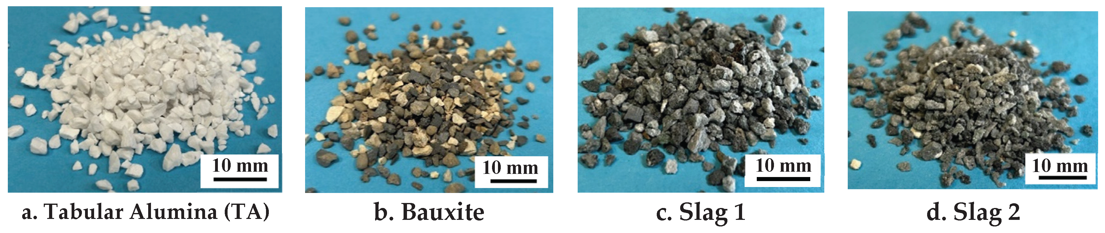
Figure 2.
Length-width ratio (left) and roundness (right).
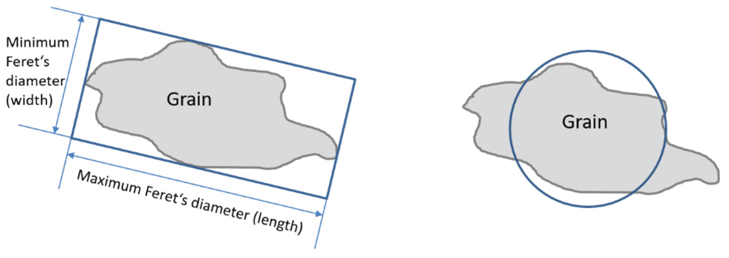
Figure 3.
Experimental setup for the corrosion behaviour test of castable samples.
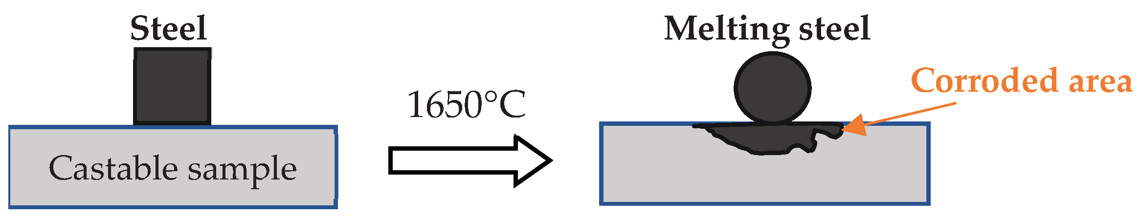
Figure 4.
X-ray diffraction pattern of the raw materials with labelled peaks.
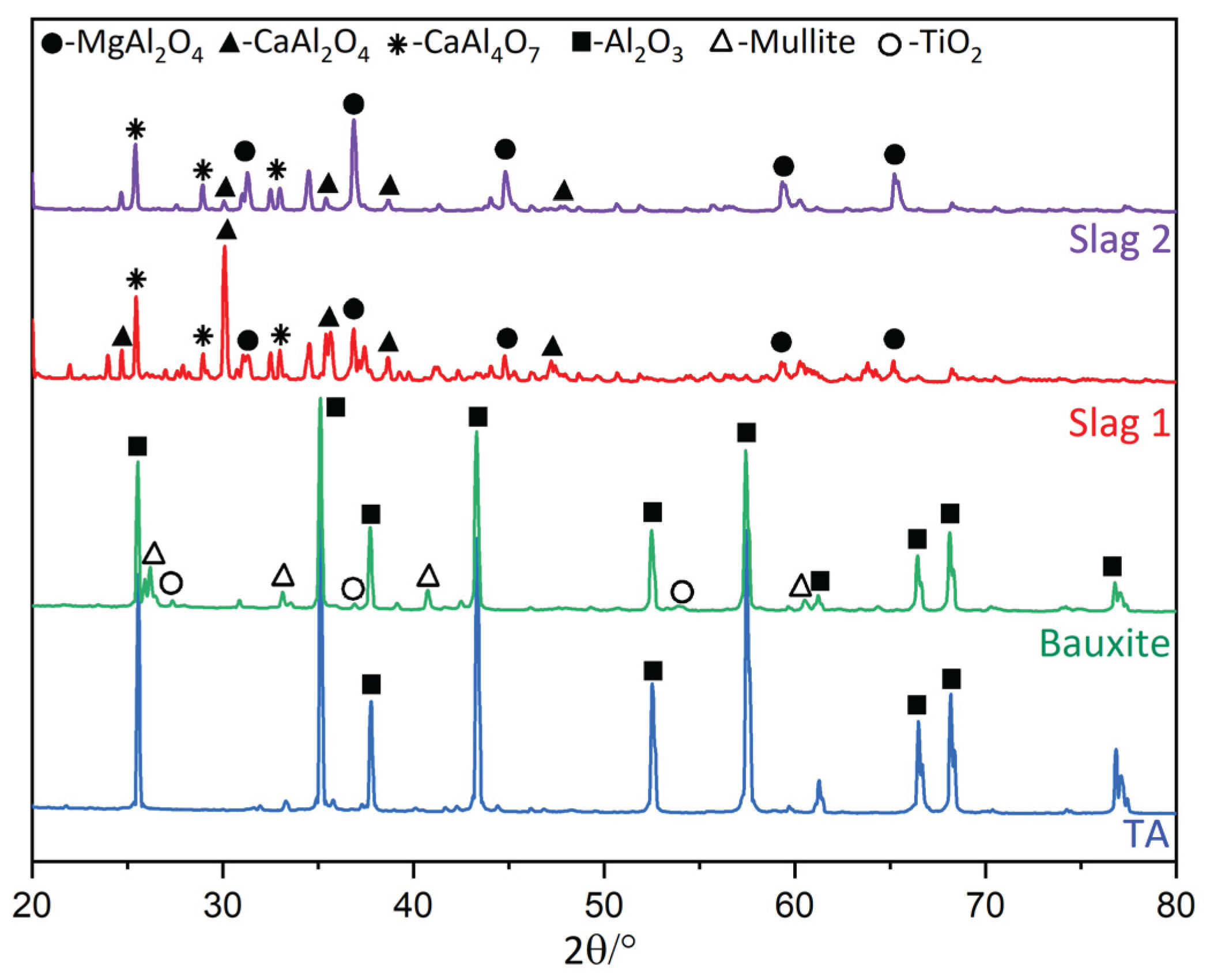
Figure 5.
Sieve analysis of the aggregates.
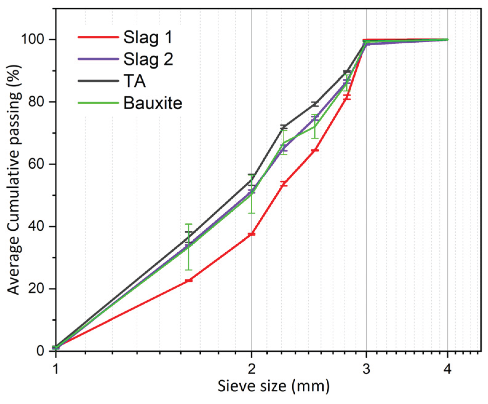
Figure 6.
SEM images of aggregates: As-received a) Slag 1, b) Slag 2 and after firing at 1500 °C for 1h in air atmosphere: c) Slag 1 and d) Slag 2.
Figure 6.
SEM images of aggregates: As-received a) Slag 1, b) Slag 2 and after firing at 1500 °C for 1h in air atmosphere: c) Slag 1 and d) Slag 2.
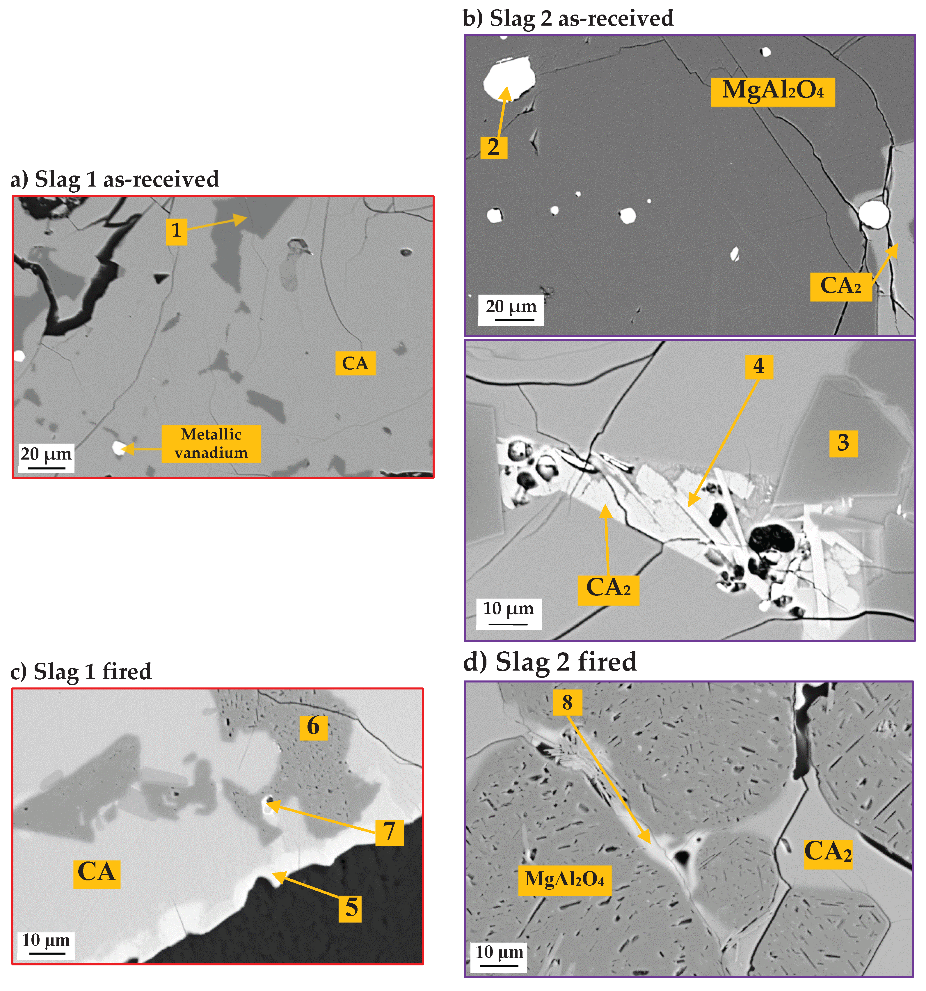
Figure 7.
Equilibrium phase regions of the Al2O3-CaO-MgO system at 1500 °C determined with FactSage.
Figure 7.
Equilibrium phase regions of the Al2O3-CaO-MgO system at 1500 °C determined with FactSage.
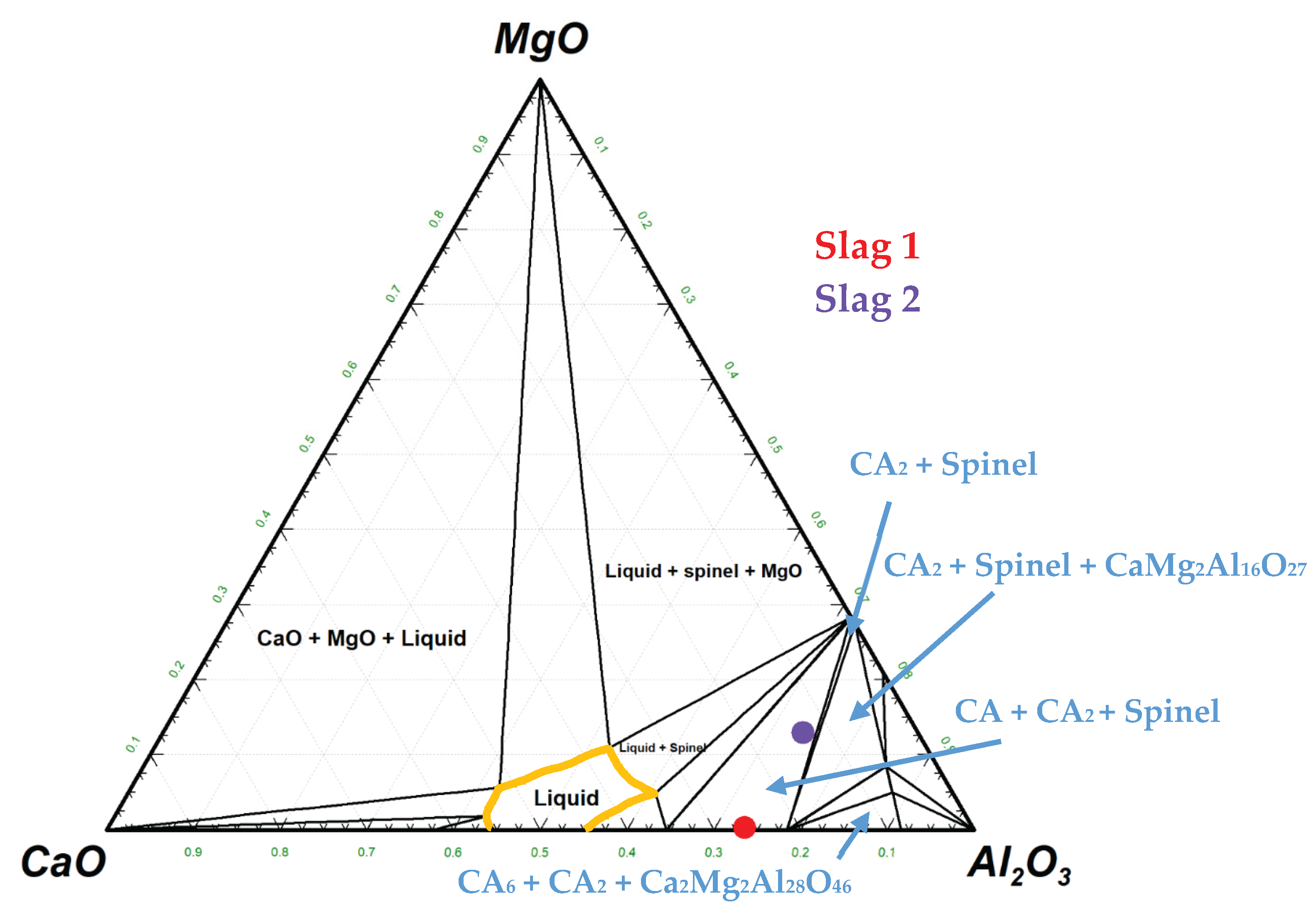
Figure 8.
SEM images of the aggregates.
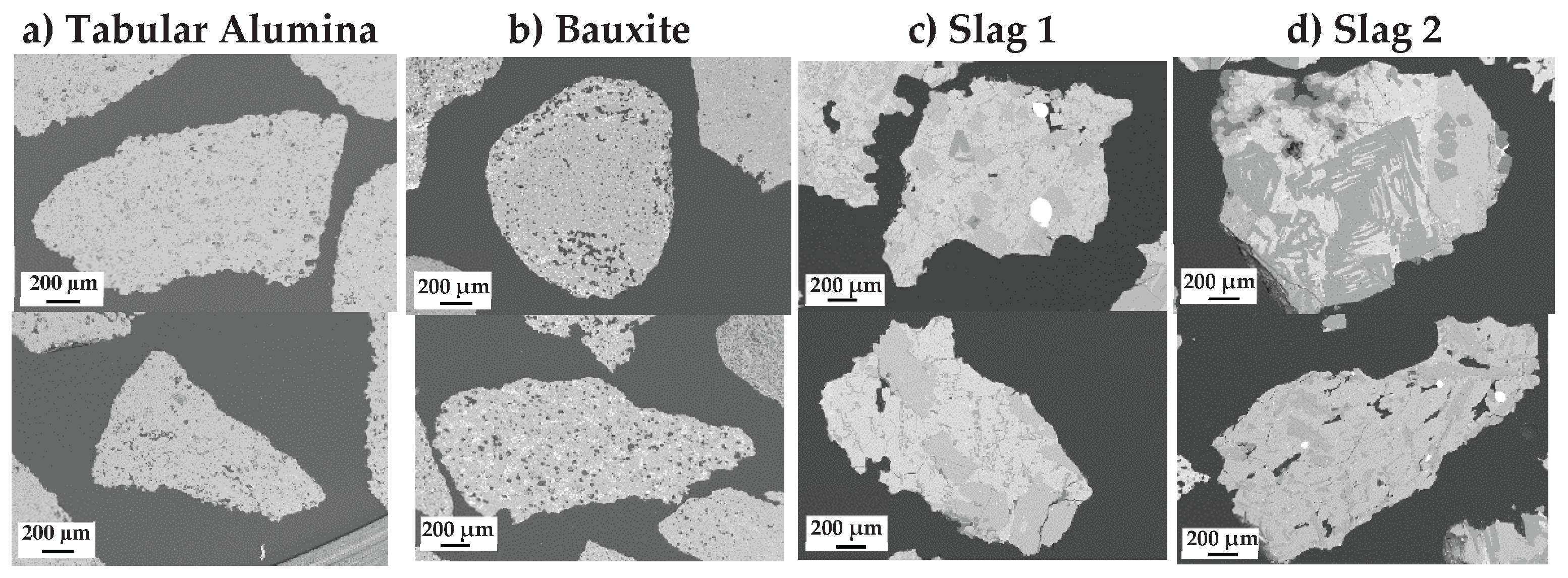
Figure 9.
Surface roughness of the raw materials.
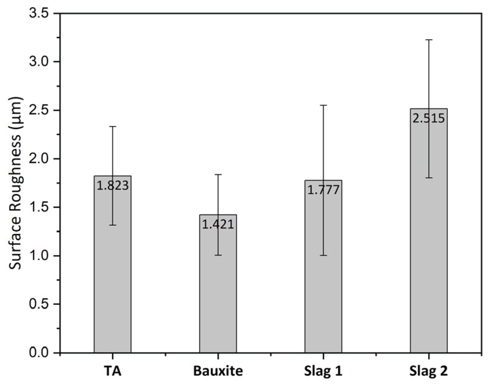
Figure 10.
a) Shape parameters analysis of raw materials, b) Length-width ratio distribution and c) Round-ness distribution.
Figure 10.
a) Shape parameters analysis of raw materials, b) Length-width ratio distribution and c) Round-ness distribution.
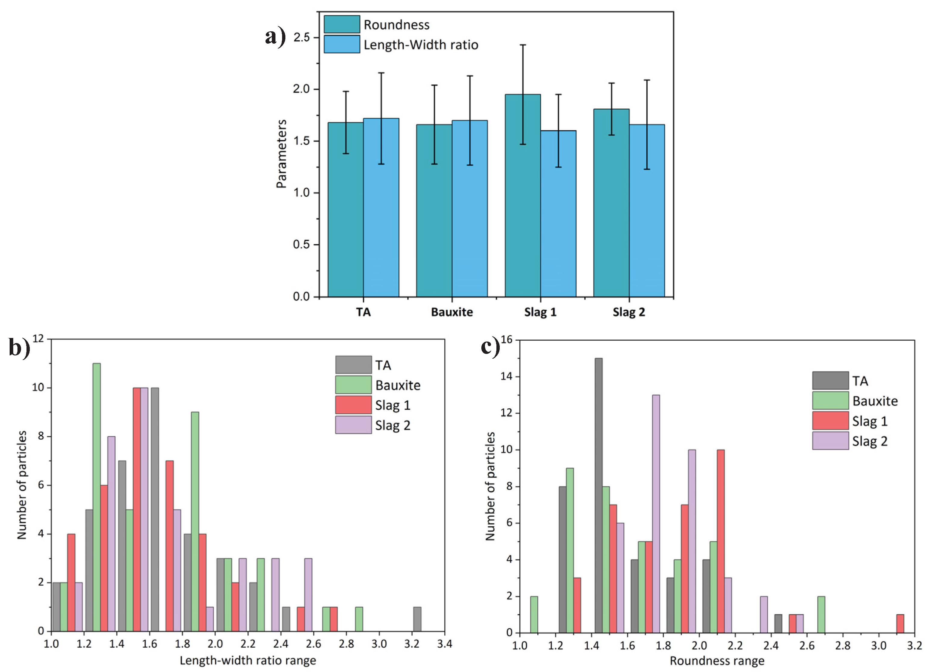
Figure 11.
a) Boxplot of nanoindentation hardness for the aggregates. Boxes represent the interquartile range with the median indicated by the red line while whiskers extend to 1.5x interquartile range, b) Representative load-indentation depth obtained at identical maximum load obtained for each material, and c) Microstructure of Slag 2 with indents on CA and spinel phases.
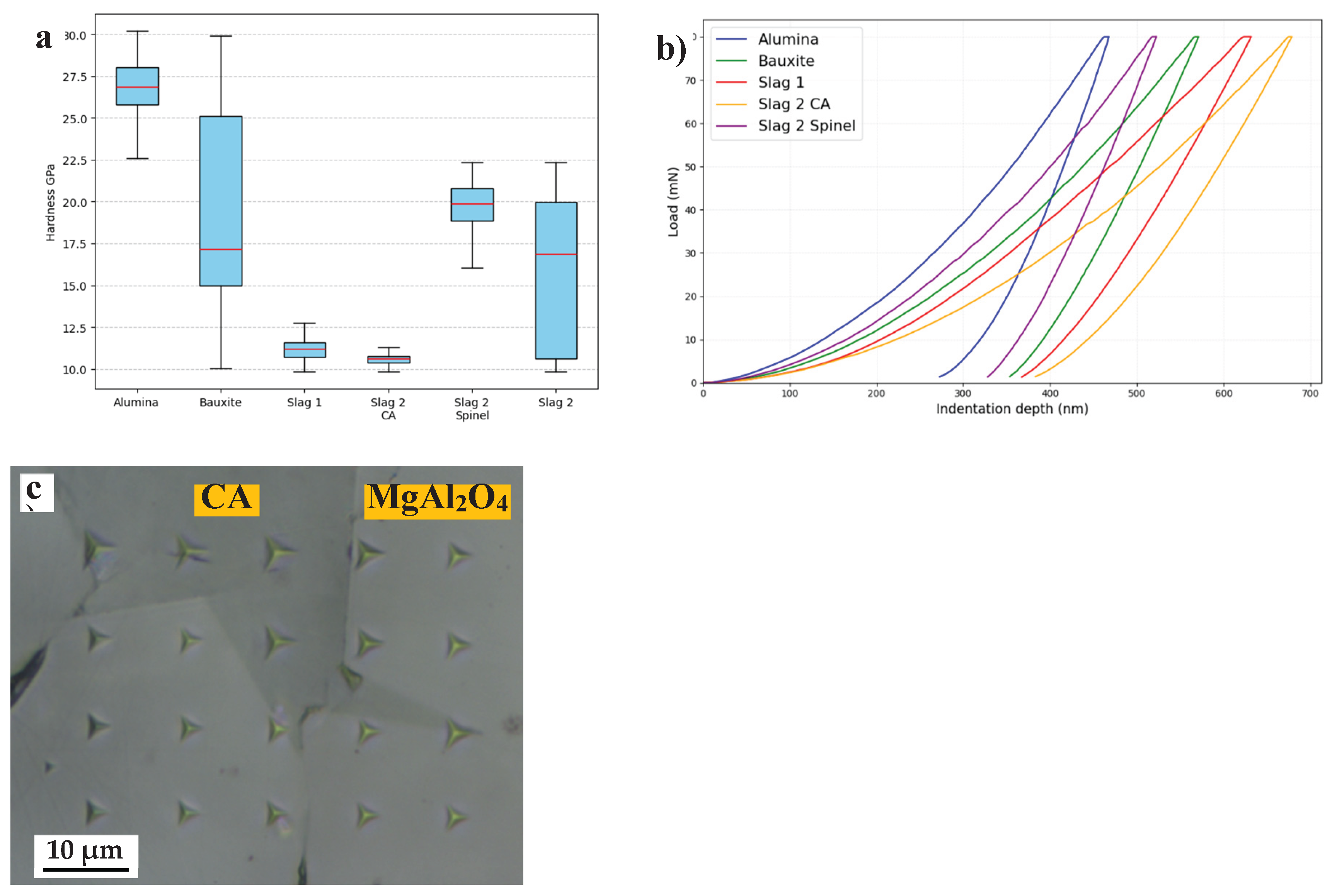
Figure 12.
XRD patterns of castables containing slags and bauxite.
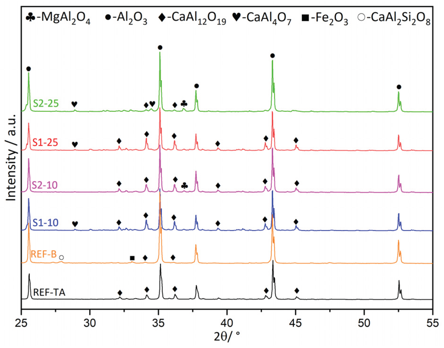
Figure 13.
Thermal expansion of castables.
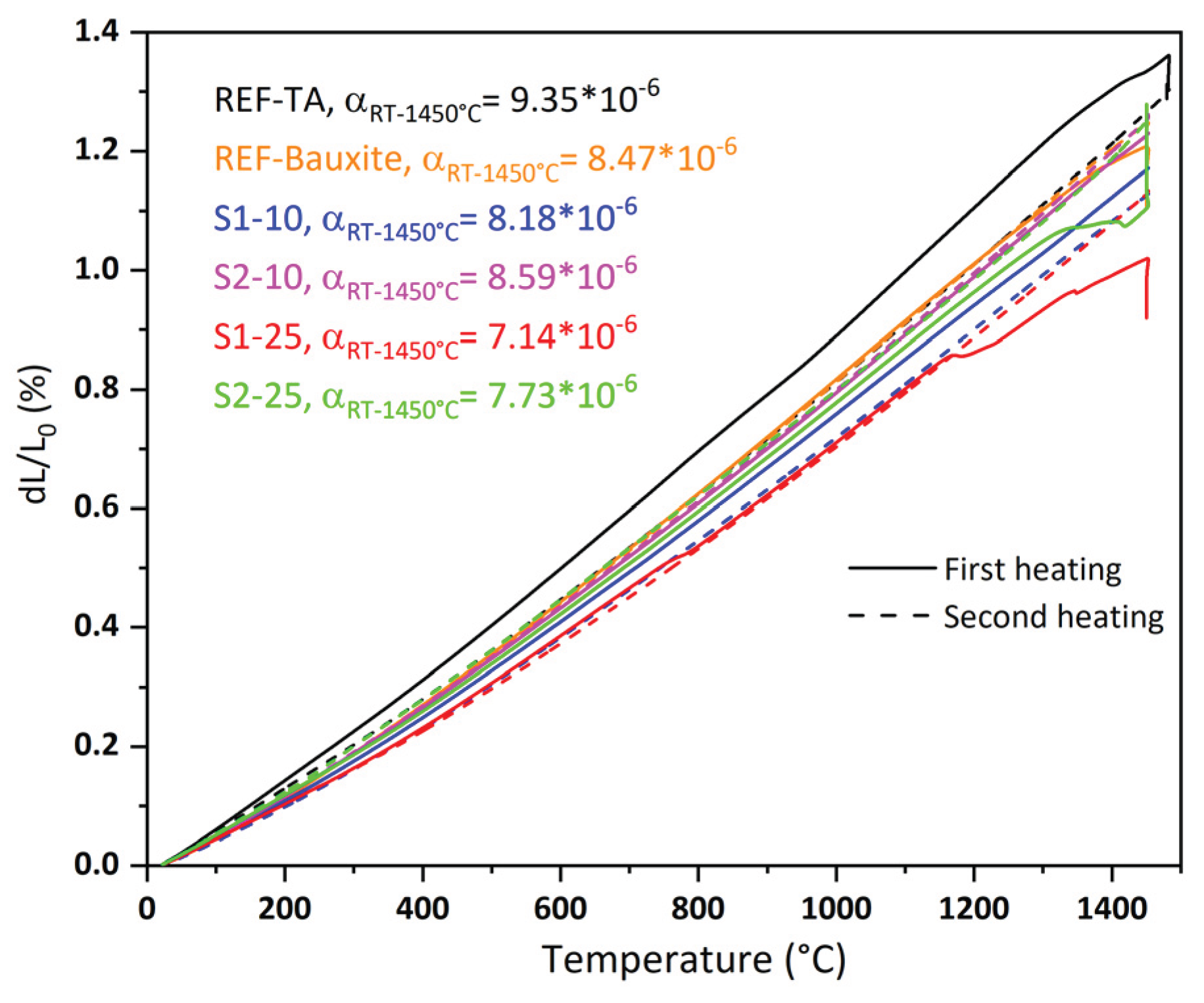
Figure 14.
Microstructure images of S1-25 containing 25 wt.% Slag 1. a) and b) overview of the slag grains in the castable and c) Interface between slag and the matrix.
Figure 14.
Microstructure images of S1-25 containing 25 wt.% Slag 1. a) and b) overview of the slag grains in the castable and c) Interface between slag and the matrix.
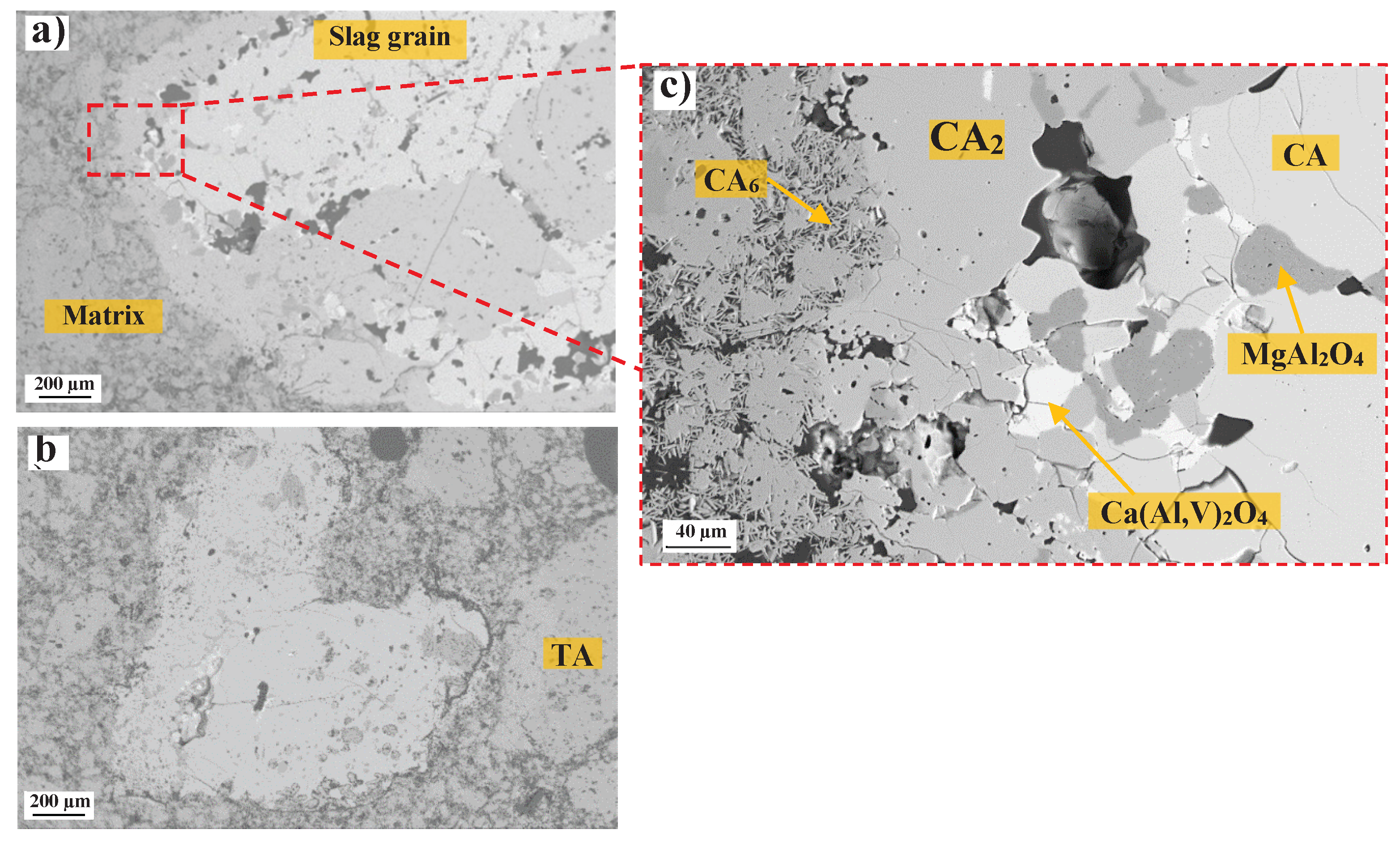
Figure 15.
Microstructure images of S2-25 containing 25 wt.% Slag 2. a) and b) overview of the slag grains in the castable and c) Interface between slag and the matrix.
Figure 15.
Microstructure images of S2-25 containing 25 wt.% Slag 2. a) and b) overview of the slag grains in the castable and c) Interface between slag and the matrix.
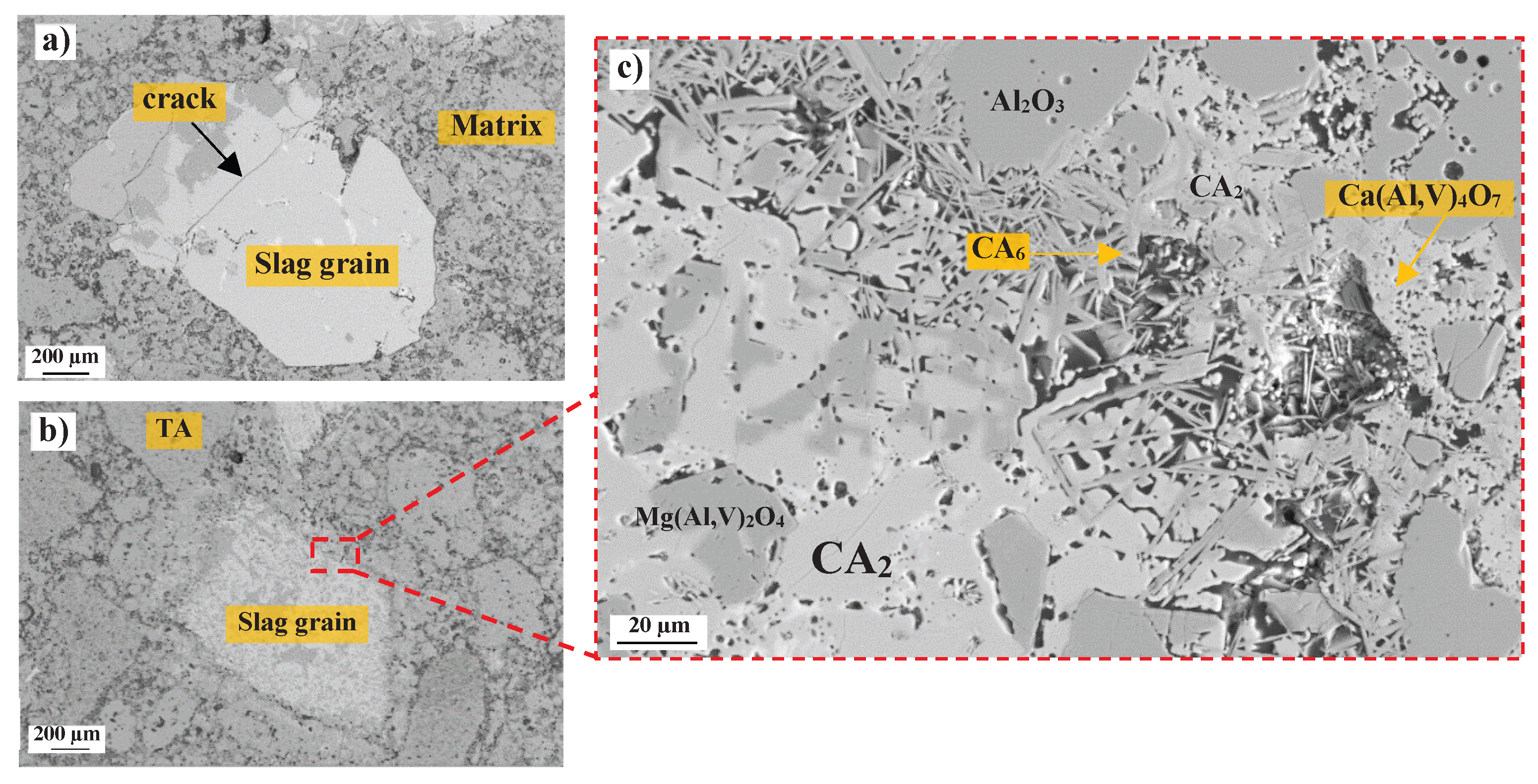
Figure 16.
Microstructure images of Ref-B containing Bauxite. a) overview of the bauxite in the castable and b) interface between bauxite and the matrix.
Figure 16.
Microstructure images of Ref-B containing Bauxite. a) overview of the bauxite in the castable and b) interface between bauxite and the matrix.
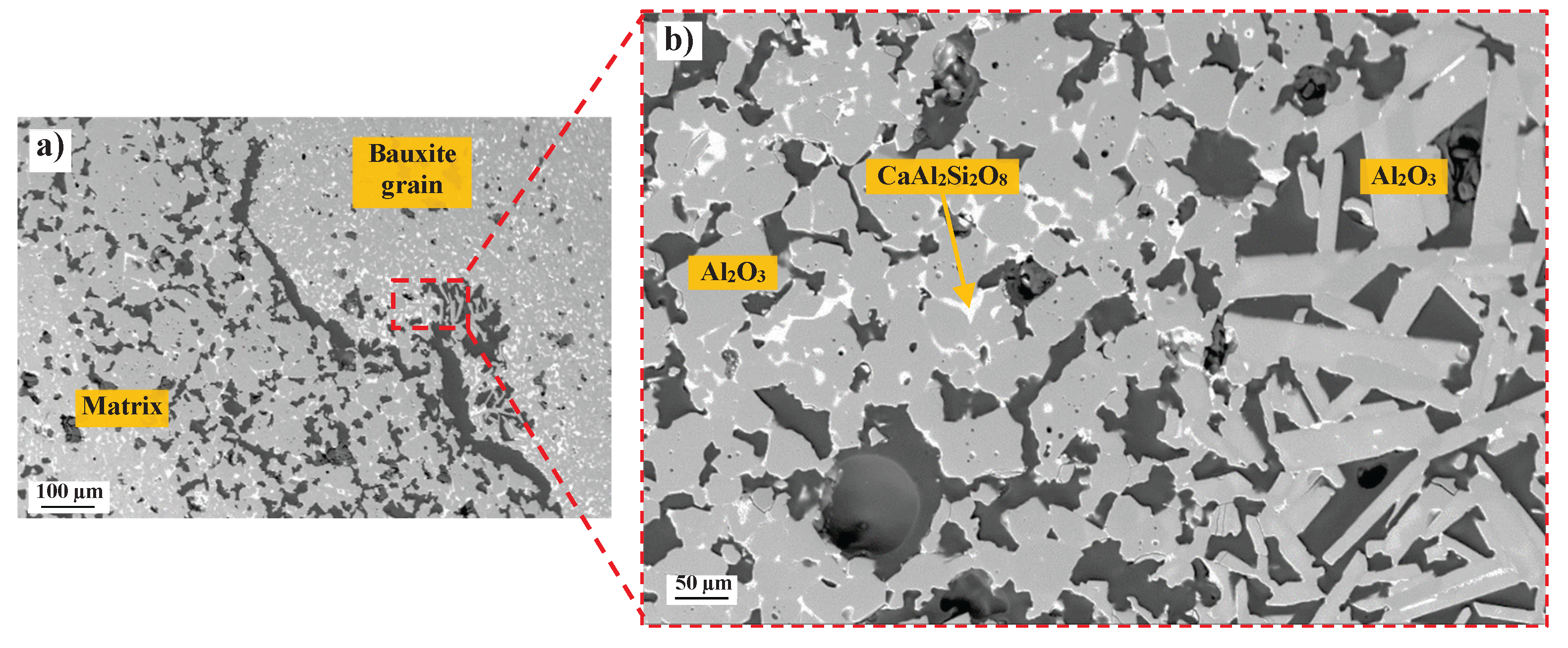
Figure 17.
Refractoriness under load (RUL) of the samples fired at 1500 °C.
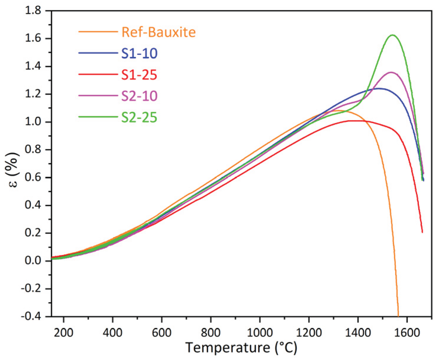
Figure 18.
Microstructures of Ref-TA after corrosion test with molten steel. a) Overview of the interface and the corresponding element mapping of aluminum, calcium, iron, and manganese and b) higher magnification of the corroded area.
Figure 18.
Microstructures of Ref-TA after corrosion test with molten steel. a) Overview of the interface and the corresponding element mapping of aluminum, calcium, iron, and manganese and b) higher magnification of the corroded area.
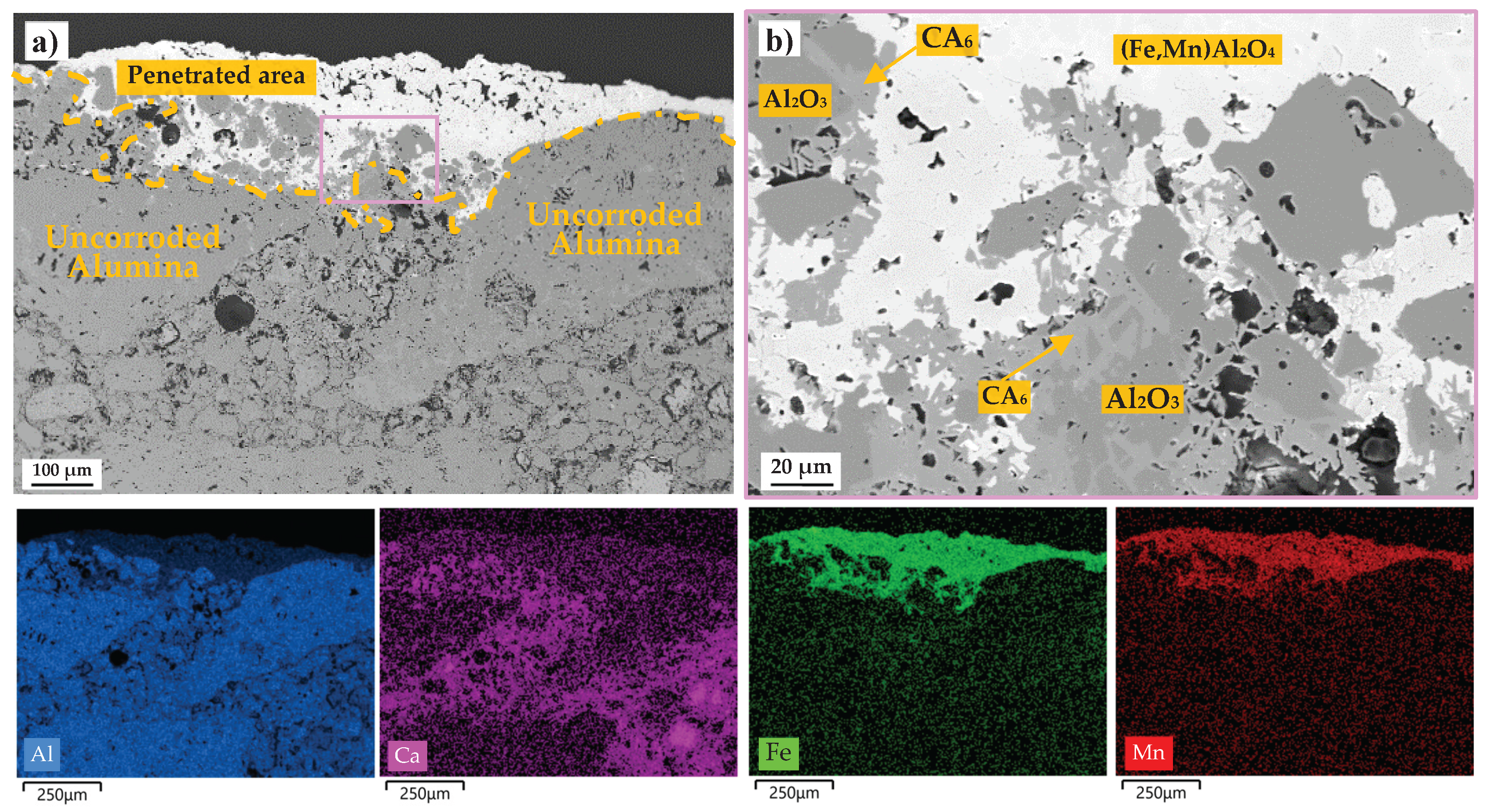
Figure 19.
Microstructures of S1-10 after corrosion test with molten steel. a) Overview of the interface and the corresponding element mapping of aluminum, calcium, iron, and manganese and b) higher magnification of the corroded area.
Figure 19.
Microstructures of S1-10 after corrosion test with molten steel. a) Overview of the interface and the corresponding element mapping of aluminum, calcium, iron, and manganese and b) higher magnification of the corroded area.
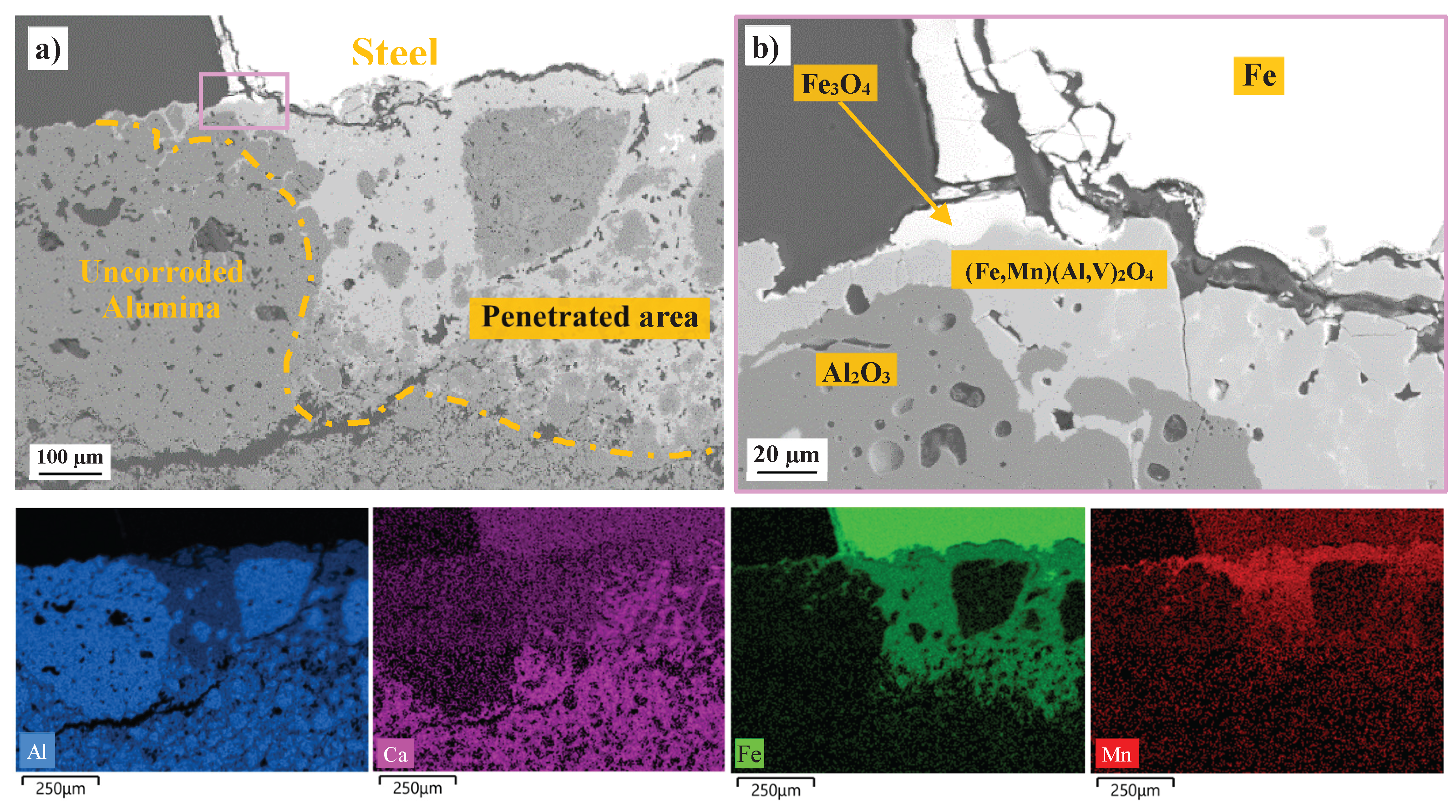
Figure 20.
Microstructures of S2-10 after corrosion test with molten steel. a) Overview of the interface and the corresponding element mapping of aluminum, calcium, iron, and manganese and b) higher magnification of the corroded area.
Figure 20.
Microstructures of S2-10 after corrosion test with molten steel. a) Overview of the interface and the corresponding element mapping of aluminum, calcium, iron, and manganese and b) higher magnification of the corroded area.
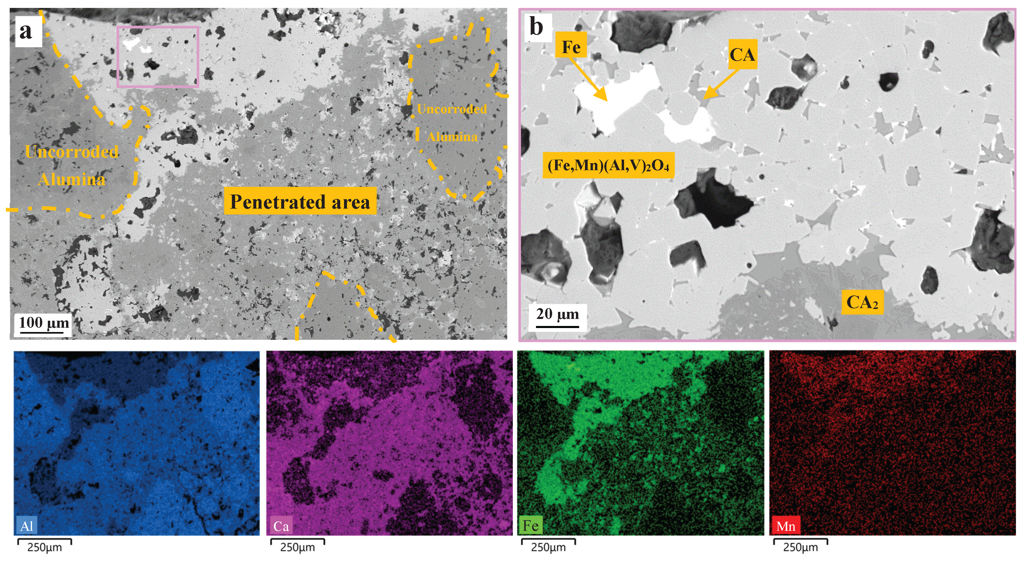
Figure 21.
Microstructures of Ref-Bauxite after corrosion test with molten steel. a) Overview of the interface and the corresponding element mapping of aluminum, calcium, iron, and manganese and b) higher magnification of the corroded area.
Figure 21.
Microstructures of Ref-Bauxite after corrosion test with molten steel. a) Overview of the interface and the corresponding element mapping of aluminum, calcium, iron, and manganese and b) higher magnification of the corroded area.
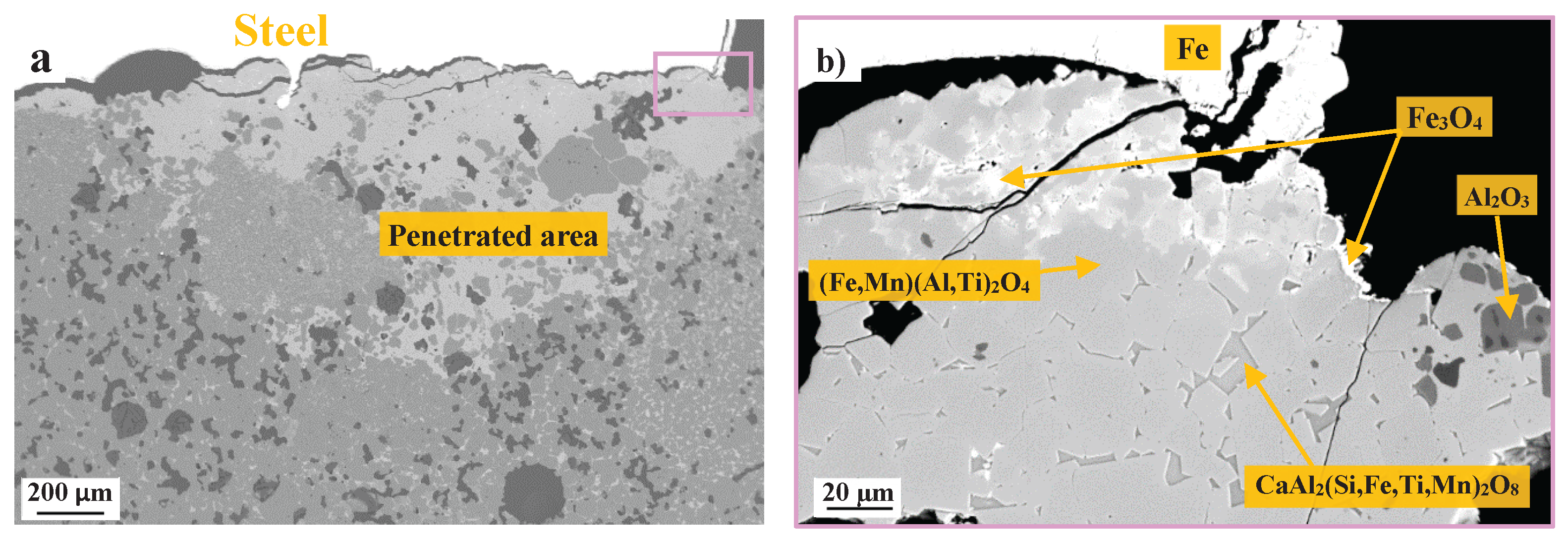
Table 1.
Formulations of the castables (vol.%).
| Raw Material | Grain Size | Sample code | |||||
|---|---|---|---|---|---|---|---|
| REF-TA | REF-B | S1-25 | S2-25 | S1-10 | S2-10 | ||
| Tabular Alumina | 1-3 mm | 34.2 | 34.2 | 25.7 | 25.7 | 30.8 | 30.8 |
| 0.5-1 mm | 9.8 | ||||||
| 0.2-0.6 mm | 9.8 | ||||||
| 0-0.3 mm | 17.1 | ||||||
| 0-0.045 mm | 9.8 | ||||||
| Reactive Alumina | <0.001 mm | 12.9 | |||||
| Secar 71 | 6.4 | ||||||
| Slag 2242 | 1-3 mm | - | - | 8.6 | - | 3.4 | - |
| Slag 2256 | 1-3 mm | - | - | - | 8.6 | - | 3.4 |
| Slag 2242 | <63 µm | - | - | - | - | - | - |
| Slag 2256 | <63µm | - | - | - | - | - | - |
| Water | 5 | ||||||
| Deflocculant | FS65 | 0.1 | |||||
Table 3.
Physical properties of the raw materials.
| Raw material | True density g.cm-3 | Porosity % | Specific surface area m2.g-1 |
|---|---|---|---|
| Slag 1 | 3.02 | 7.3 | 0.59 ± 0.03 |
| Slag 2 | 3.06 | 2.1 | 0.24 ± 0.01 |
| Tabular Alumina | 3.92 | 0.9 | 1.00 ± 0.06 |
| Bauxite | 3.81 | 8.9 | 0.74 ± 0.04 |
Table 4.
EDS point analysis results (at.%) associated to the slags microstructures before and after firing.
Table 4.
EDS point analysis results (at.%) associated to the slags microstructures before and after firing.
| Point. | Phase | O | Mg | Al | Ca | Si | S | V | Fe | Ti | Mn |
|---|---|---|---|---|---|---|---|---|---|---|---|
| 1 | Spinel Mg(Al,V)2O4 | 55.4 | 14.6 | 29.5 | 0.13 | - | - | 0.31 | - | - | |
| 2 | Metallic V + Si, Mn, Fe | 25.5 | 71.1 | 1.8 | 1.6 | ||||||
| 3 | Spinel Mg(Al,V)2O4 | 52.5 | 13.2 | 31.9 | 2.38 | ||||||
| 4 | Goldmanite Ca3(Al,V,Ti)2(Si,Mg)3O12 | 54.6 | 2.80 | 21.0 | 7.00 | 4.30 | 6.43 | 3.64 | |||
| 5 | Krotite-type (Ca12(Al,V,Si,S)14O33) | 54.8 | - | 22.8 | 16.4 | 2.36 | 0.55 | 3.17 | - | - | |
| 6 | Spinel Mg(Al,V)2O4 | 56.2 | 14.2 | 27.9 | 0.87 | - | - | 0.57 | 0.32 | - | |
| 7 | Mayenite-type (Ca12(Al,V,Si,Ti,Fe)14O33 | 60.9 | 0.67 | 10.8 | 16.6 | 1.05 | - | 1.85 | 0.92 | 7.21 | |
| 8 | Krotite-type | 54.3 | - | 22.0 | 15.6 | 4.23 | - | 3.87 | - | - |
Table 6.
Physical and mechanical properties of samples after firing at 1500 °C.
| Sample | Open porosity % | True density g/cm3 |
CCS (MPa) |
CMOR (MPa) |
HMOR 1400°C (MPa) |
E modulus (GPa) | G modulus (GPa) |
| REF-TA | 17.5 | 4.02 | 259.0 ± 16 | 42.5 ± 2.2 | 23.8 ± 1.6 | 133 ± 8.5 | 59.4 ± 1.8 |
| REF-Bauxite | 17.8 | 3.98 | 225.3 ± 9.2 | 34.8 ± 2.2 | 1.30 ± 0.18 | 159 ± 4.6 | 16.2 ± 0.3 |
| S1-10 | 20.9 | 3.86 | 95.38 ± 23 | 21.8 ± 2.1 | 7.49 ± 1.89 | 122 ± 8.2 | 13.0 ± 0.6 |
| S1-25 | 22.0 | 3.86 | 81.57 ± 11 | 9.25 ± 1.2 | 4.69± 0.23 | 54.7 ± 2.5 | 21.2 ± 1.7 |
| S2-10 | 20.9 | 3.93 | 204.5 ± 23 | 24.8 ± 3.5 | 12.8 ± 1.25 | 126 ± 1.6 | 13.6 ± 0.3 |
| S2-25 | 24.0 | 3.89 | 50.10 ± 3.5 | 12.1 ± 2.4 | 3.4± 1.48 | 70.0 ± 3.8 | 33.1 ± 0.3 |
Disclaimer/Publisher’s Note: The statements, opinions and data contained in all publications are solely those of the individual author(s) and contributor(s) and not of MDPI and/or the editor(s). MDPI and/or the editor(s) disclaim responsibility for any injury to people or property resulting from any ideas, methods, instructions or products referred to in the content. |
© 2026 by the authors. Licensee MDPI, Basel, Switzerland. This article is an open access article distributed under the terms and conditions of the Creative Commons Attribution (CC BY) license (http://creativecommons.org/licenses/by/4.0/).
Copyright: This open access article is published under a Creative Commons CC BY 4.0 license, which permit the free download, distribution, and reuse, provided that the author and preprint are cited in any reuse.


