
Submitted:
09 February 2026
Posted:
10 February 2026
You are already at the latest version
Abstract
Photovoltaic (PV) plants are often planned for a 25–30-year module service life, yet field experience in demanding climates indicates that effective lifetimes can be much shorter and that dry-only insulation checks may underestimate wet-condition risk. Repowering after ~5 years can restore yield and reduce operational trips, but it com-presses PV waste and manufacturing into repeated surges. We review evidence that moisture (dew/rain), especially around sunrise, can activate leakage pathways and reduce insulation resistance (ground impedance, Risol), including IEC-conformant wet leakage testing of field-aged modules showing a dry-pass/wet-fail population. We also summarise a delamination-driven pathway from water ingress to discharge channels, inverter shut-down and potential damage. To mitigate environmental impacts under frequent repowering, we discuss repowering-ready module designs using soft polydi-methylsiloxane (PDMS) gel encapsulation enabling room-temperature delamination, very clean high-efficiency recycling and high component reuse. A transparent 30-year scenario model illustrates “year-5” waste surges and a 6× module throughput multi-plier under 5-year repowering. We conclude that demanding-climate sites with rapid repowering should combine risk-based wet-condition insulation verification with documented and auditable low-emission end-of-life processing enabled by disassem-blable module architectures.
Keywords:
photovoltaics
; repowering
; revamping
; reliability
; insulation resistance
; wet leakage
; dew
; delamination
; polydimethylsiloxane (PDMS)
; circular economy
; PV waste
1. Introduction
PV is widely communicated and financed with an implicit ~30-year module service-life expectation, yet a subset of plants in demanding climates are repowered after ~5 years. This is not a rhetorical exaggeration: where repeated inverter trips, delayed morning startup, and escalating downtime become routine, early replacement becomes the pragmatic asset-management choice. In parallel, ongoing improvements in module efficiency and declining costs reinforce the economic incentive to replace earlier, especially where area and grid connection are fixed constraints.
The sustainability consequence is mechanical: if repowering occurs every 5 years, then within a 30-year planning horizon 6 complete module sets are deployed and decommissioned. That creates repeated waste surges and repeated manufacturing demand. In other words, the sustainability outcome is governed by the repowering interval, not by the nominal service-life expectation printed in a datasheet.
This paper is written with a practical premise: repowering after ~5 years will occur in demanding climates (for at least a nontrivial segment of the fleet) due to a combination of reliability constraints and technology upgrading. The goal is therefore not to argue whether repowering “should” happen, but to clarify why it happens, why wet-condition insulation is central, and how the environmental impact can be reduced when repowering becomes frequent. The central technical message is that field screening is commonly performed in dry conditions for speed, while wet operation is routine and can reveal latent failures; the central sustainability message is that frequent repowering requires end-of-life routes that are both high-efficiency and low-emission, preferably enabled by repowering - ready module construction.
1.1. Repowering as an Operational Reality, Not an Exception
Solar PV plant revamping and repowering have been analysed as technical and economic decisions with multiple alternatives, strongly dependent on site constraints and assumptions [1]. Module replacement has also been discussed as a mechanism that can accelerate technology upgrading and market entry, by allowing a mature BOS and grid connection to host higher-performance modules [2]. At fleet scale, such decisions matter more as global deployment expands and the installed base ages [3]. Technology reporting confirms continuing efficiency improvements and module power increases [4], while cost assessments show PV as a competitive generation option in many regions [5]. These trends make repowering attractive even when the existing plant is not yet “end of life” in the conventional sense.
In demanding climates, the economic incentive is frequently reinforced by a reliability incentive: repeated protective trips and inverter unavailability translate into high opportunity cost. When that cost accumulates early, repowering becomes the simplest method to restore stable operation. It is therefore realistic to treat 5-year repowering as an operational practice that must be addressed in sustainability planning rather than as a hypothetical corner case.
1.2. Short Effective Service Life in Demanding Climates
Reduced real lifetime has been discussed explicitly together with its economic consequences, showing how shorter service life changes project economics and replacement strategy [6]. Literature on harsh deployments reports that degradation and reliability challenges can be accelerated under combined stressors such as heat, humidity, UV, dust, and salt. Long-term performance and reliability analyses under tropical conditions report notable reliability challenges [7]. Field exposure of crystalline-silicon modules has shown performance evolution under real outdoor conditions that can diverge from simplified planning assumptions [8]. Degradation evaluations after only a few years in tropical environments show that early degradation and defect accumulation can be significant depending on climate and construction [9]. Similar conclusions appear in studies of harsh desert and arid deployments, where climatic stressors affect module behaviour and performance [10]. In-situ evaluation under harsh Moroccan conditions likewise reports early degradation of various technologies [11].
These studies do not imply that all PV plants will repower after five years. They do establish, however, that in demanding climates the effective service life can be shortened enough that early replacement becomes practical, and that in those cases sustainability analysis must reflect the real replacement interval rather than a nominal expectation.
1.3. Wet-Condition Insulation is Routinely Relevant and Commonly Under-Screened
Insulation resistance (ground impedance, Risol) between PV DC circuits and accessible conductive parts/ground is a key safety and reliability metric: low Risol can trigger inverter protection and indicates potentially hazardous leakage, and wet operation is routine because dew, fog, and rain films commonly form (especially around sunrise), while colder modules can also raise open-circuit voltage [12,13,14]. Although IEC 61215-2 defines a wet leakage current compliance test (MQT 15) using a resistance–area product criterion (Rwet × A ≥ 40 MΩ·m² for modules > 0.1 m²) [15], this is typically used for type approval of new designs rather than routine screening of field-aged modules, where O&M practice often defaults to faster dry checks. That convenience can misrepresent risk because moisture activates surface/edge leakage pathways and because degradation at polymeric interfaces (frame edges, backsheets, junction boxes) can create wet-activated conduction routes that differ across backsheet constructions and evolve over time [16,17,18,19,20], with plant-scale impacts documented under severe moisture exposure such as flooding [21]. High-voltage stress mechanisms (e.g., PID) may further interact with string voltage and leakage conditions, particularly in harsh environments [22]. Recent IEC wet testing of N = 37 field-aged crystalline-silicon modules demonstrated that dry-only measurements can strongly overestimate wet insulation and revealed a dry-pass/wet-fail population [23]. This population is operationally critical because it creates latent trip risk during routine wet mornings: modules appear acceptable in dry screening yet fail under wet conditions. Figure 1 summarises the outcome categories at a conceptual level based on published statistics.
1.4. Sunrise Window: Wet Surfaces can Coincide with High DC Voltage
The co-occurrence of wet surfaces and high string voltage is most relevant around sunrise. Moisture films can persist into morning hours, while module temperature remains low and increases Voc. In practice, this explains why insulation-related events often cluster around sunrise and why inverters can remain off until Risol rises above protection thresholds. Figure 2 provides a stylised proxy for this combined window and is included for clarity (not as a site-specific predictive model).
1.5. Failure Escalation: From Delamination to Inverter-Level Impacts
Wet leakage issues are not only nuisance trips. A documented field pathway links edge delamination to water penetration and the formation of discharge channels between string conductors and grounded frames, leading to inverter switch-off and, after repeated discharges, potentially inverter downtime and damage [24]. Because one inverter affects multiple strings, a limited number of defective modules can propagate into inverter-level energy losses and increased operational risk. This “multiplication effect” shifts repowering from an economic optimisation into a risk-control decision. Figure 3 summarises the escalation chain, from edge delamination and water ingress to discharge channels, Risol reduction, inverter events, and downtime/damage.
1.6. Repowering Pressure is Also Technology-Driven Efficiency Improvements
Repowering is not driven by reliability alone. Ongoing improvements in module efficiency and power density strengthen the incentive to replace, because the same area and BOS can deliver higher output after repowering. Figure 4 provides an illustrative long-term efficiency trend consistent with published technology reporting [4]. When efficiency gains coincide with reliability constraints (wet trips, escalating downtime), repowering becomes both technically and economically rational.
1.7. Objectives and Paper Logic
This paper adopts a practical stance: repowering after ~5 years will occur for a subset of plants in demanding climates despite the ~30-year expectation. The question is how to reduce the environmental impact when this becomes the operating reality.
The objectives are therefore:
- To summarise a plausible failure escalation pathway linking module defects to inverter-level impacts [24].
- To quantify, using a transparent 30-year scenario model, how a 5-year repowering practice changes waste timing (“surges”), module throughput multipliers, and manufacturing diversion.
- To argue, on technical and sustainability grounds, that repowering-ready module construction enabling clean disassembly and high direct reuse—specifically soft PDMS-gel encapsulation—reduces the environmental burden of inevitable repowering [25].
2. Materials and Methods
2.1. Evidence Base
The paper synthesises published evidence on: wet leakage standards and field-aged wet insulation [15,23]; dew/rain moisture relevance [12]; insulation safety and modelling [13,14]; backsheet-driven insulation issues [16,17,18,19,20]; flooding impacts [21]; PID under high voltages [22]; delamination-driven inverter impacts [24]; and demountable encapsulation and recycling using soft PDMS/polysiloxane gels [25]. Sustainability discussion is grounded in EoL management literature [26] and in established analysis of greenhouse-gas emissions associated with PV electricity [27].
2.2. Functional Unit and System Boundary
The functional unit is 1 kW of installed module capacity delivering service over a 30-year planning horizon (the commonly used expectation). The scenario model focuses on modules (dominant repeated mass flow under frequent repowering). BOS is assumed largely reusable during repowering; BOS impacts are addressed qualitatively in limitations.
2.3. Scenarios
We define three scenarios:
- S0 (rapid repowering): full module replacement every 5 years → 6 complete module sets over 30 years.
- S1 (sensitivity): full module replacement every 10 years → 3 complete module sets over 30 years.
- S2 (baseline expectation): no replacement within 30 years → 1 module set over 30 years.
The central comparison is S0 versus S2, because it captures the mismatch between the ~30-year expectation and the practical ~5-year repowering behaviour.
2.4. Indicators
Three indicators follow directly from the scenarios:
- Waste timing: replacement events create discrete waste “surges” over time.
- Module throughput multiplier: number of module sets installed per 30 years (mechanical multiplier for manufacturing and EoL flows).
- Stylised manufacturing diversion: replacement demand consumes factory output that could otherwise supply new deployment.
These indicators are deliberately first-order: they quantify scale and timing without requiring a detailed plant-specific optimisation.
3. Results
3.1. Wet-Condition Operation Creates a Sunrise Risk Window
Moisture films (dew, rain) tend to peak around sunrise, while string voltage can be high because cell temperature is low (higher Voc). This combination amplifies the probability that moisture-activated leakage pathways reduce Risol and trigger inverter ground-fault protection [12,13,14,23]. The key operational point is not only that wet conditions happen, but that they happen at a time when voltage conditions are unfavourable for insulation margins. Figure 2 provides the stylised proxy of this combined window.
3.2. Dry-Only Screening can Miss Wet Failures at Non-Trivial Rates
IEC-conformant wet leakage testing of field-aged modules shows that dry measurements can systematically overestimate wet insulation and that a dry-pass/wet-fail population exists [23]. In plant practice this means: a module population may appear acceptable under convenient dry screening yet still generate repeated trips under routine wet mornings. This is consistent with the O&M observation that sunrise events can persist until the real wet-condition leakage pathways are identified. Figure 1 summarises the outcome pattern at a conceptual level.
3.3. Delamination-Driven Escalation Increases Repowering Pressure
The delamination pathway provides a mechanism for escalation: edge delamination → water ingress → conductive wet interfaces → discharge channel formation to grounded frames → inverter switch-off due to low Risol → repeated discharges stressing protective components → downtime and potentially damage [24]. This coupling creates a non-linear maintenance curve: early morning trips can evolve into high-cost inverter impacts, which shifts the operator’s decision towards larger replacement campaigns. Figure 3 summarises the mechanism.
3.4. Waste Timing: 5-Year Repowering Produces Repeated “Year-5 Surges”
To visualise the discontinuity between a nominal long-life loss progression and a rapid repowering practice, Figure 5a reproduces the Weibull cumulative probability-of-loss curve used in the IRENA/IEA-PVPS PV panel waste model for the regular-loss scenario (Weibull form , with years and ) and overlays the 5-year repowering trigger adopted here for scenario S0 [28]. Importantly, the original IRENA/IEA-PVPS waste model explicitly excludes repowering; the 5-year threshold is therefore introduced in this study as an exogenous scenario assumption to represent observed rapid repowering practice in demanding climates [28]. Applying this 5-year trigger yields replacement events at years 5, 10, 15, 20, 25, and 30. Under S2, the primary decommissioning event occurs at year 30. Figure 5b translates these events into cumulative waste expressed in module-set equivalents. The result is mechanical: within a 30-year planning horizon, 5-year repowering requires six complete module sets (6× throughput) and therefore generates repeated waste “surges”, rather than a single late-horizon decommissioning wave
3.5. Module Throughput Multiplier Scales with Repowering Interval
Figure 6 summarises the number of module sets manufactured per 30-year service. The multiplier is again mechanical: S0 corresponds to 6 module sets (6×), S1 to 3 sets (3×), and S2 to 1 set (1×). This multiplier is the first-order driver of repeated manufacturing, transport, and EoL processing under short repowering cycles.
3.6. Manufacturing-Capacity Constraint: Replacement Demand Diverts Output from New Deployment
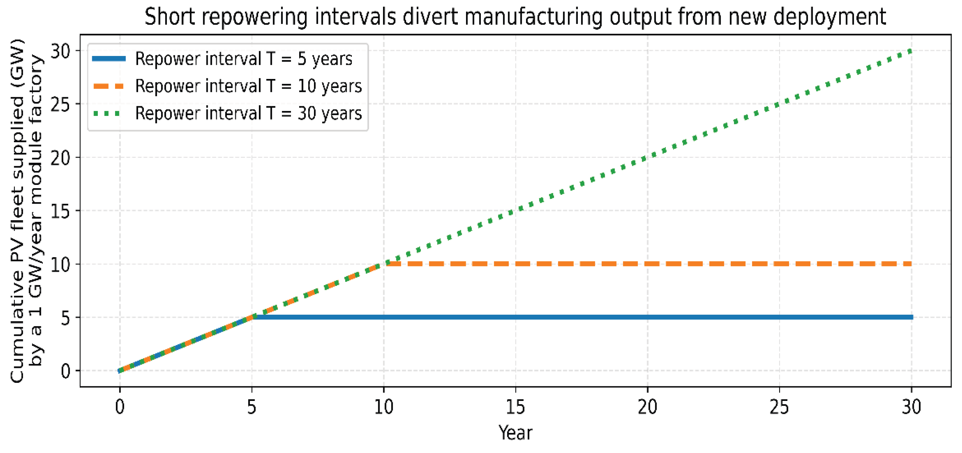
At system scale, replacement demand competes with new deployment for manufacturing output. The stylised factory model in Figure 7 illustrates the effect: if a fixed manufacturing capacity supplies both growth and replacement, then short repowering intervals cause earlier saturation of “new fleet supplied” because output is increasingly consumed by replacement. This is an energy-transition constraint when replacement demand becomes substantial, because it reduces how much net new capacity can be added for a given manufacturing base.
4. Discussion
4.1. The core Discontinuity: 30-Year Expectation versus 5-Year Practice
If a plant is planned and marketed with a ~30-year module expectation, but in practice is repowered after ~5 years, then sustainability analysis based on the nominal expectation will understate both waste and repeated manufacturing. The difference is not subtle: 5-year repowering implies six module sets and six waste events per 30 years. This is a decisive multiplier, independent of the details of any LCA model.
The real question is therefore operational: why does a plant become repowering-prone after ~5 years, and how can the environmental impact be reduced when repowering becomes the practical path? The evidence reviewed here supports two technical drivers that are consistent with field observations: (i) wet-condition insulation behaviour that can be underestimated by dry screening, and (ii) delamination-driven escalation that couples module defects to inverter availability [23,24]. Together with technology upgrading pressure (efficiency gains) [4], these drivers make repowering after ~5 years an expected practice for a subset of demanding sites.
4.2. Wet-Condition Insulation Verification: A Practical Lever, not a Laboratory Detail
The fact that IEC wet leakage testing is primarily used for type approval [15] while field screening is commonly dry creates a practical gap. Wet operation is routine, and field-aged evidence shows that dry-only screening can miss wet failures [23]. In demanding climates, and particularly where sunrise trip patterns occur, wet-condition insulation verification should be treated as a risk-based O&M tool.
This does not require turning every plant into a laboratory. The operational intent is simple: identify module/string populations likely to trip under routine wet mornings and prevent escalation. Practical triggers for wet-condition verification include:
- repeated sunrise trips and delayed morning start-up,
- Risol alarms correlated with dew/rain events,
- visible edge/interface degradation, and
4.3. Why Delamination Escalation Changes the Repowering Decision Threshold
The delamination pathway in [24] explains why repowering can become urgent: once discharge channels and repeated discharges occur, the problem becomes an inverter-availability and potential damage issue rather than a mild performance loss. The “multiplication effect” is practical: a limited number of defective modules can affect an inverter and therefore propagate into large energy losses and high O&M burden. Under those conditions, full replacement campaigns become the economically rational risk-control decision, even if sustainability outcomes worsen.
This is the link between technical reliability and sustainability: if we want to reduce the environmental impact of inevitable repowering, we must address both the triggering failure modes (wet insulation, delamination pathways) and the end-of-life processing of repeated surges.
4.4. Repowering-Ready Circular Module Construction: Why Soft PDMS Gels Matter
If repowering after ~5 years is reality for a segment of the fleet, then the sustainability problem is not only “how to recycle more”, but “how to repower without creating high-emission waste handling and low-value disposal”.
Here the circular design choice becomes central. Soft PDMS/polysiloxane gel lamination has been reported as an approach that enables room-temperature mechanical delamination, high recycling efficiency, and high direct reuse fractions, while avoiding high-temperature burning and aggressive chemical etching [25]. In that framework, a large portion of the module mass can be recovered as reusable components rather than being downcycled or disposed, and processing time can be reduced (rapid disassembly) [25]. Separate work on silicone-gel-laminated modules reports very low degradation rates over multi-decade observation and supports the general claim of high stability for gel-based encapsulation [25].
The key point for this manuscript is not a theoretical circular-economy argument; it is a practical one:
- Repowering will happen (for reliability and/or upgrading reasons).
- Therefore, the sustainability result depends on whether the module can be cleanly and quickly dismantled, enabling high-value reuse and low-emission processing during repeated surges.
- A demountable PDMS-gel architecture is therefore not an aesthetic design feature; it is an enabling technology for sustainable repowering in demanding climates [25].
Cell replacement during repowering
A demountable architecture also changes what “repowering” can mean. In conventional lamination, modules are effectively sealed irreversibly; repowering means discarding the entire module. With room-temperature delamination and a re-enterable laminate architecture, repowering can be structured to reuse the non-cell components (glass, frame, junction box where applicable) and replace the cell string set with higher-efficiency cells during scheduled repowering cycles. This is a logical engineering consequence of demount ability; and the high reuse fractions reported for soft gel lamination support the feasibility of component reuse in practice [25]. (The exact implementation depends on manufacturing and safety qualification, but the design direction is clear: repowering becomes cleaner when disassembly and reuse are designed in from the start.)
4.5. End-of-life governance: why “certified clean recycling” is required under surges
Repeated repowering surges stress collection and recycling systems. End-of-life management literature shows that recycling performance varies widely by process choice and that the difference between high-quality recovery and low-grade handling is material for environmental outcomes [26]. When repowering occurs every five years, EoL routing is not a distant issue; it is a recurring operational requirement.
Demountable PDMS-gel designs directly support certified clean processing because they avoid reliance on high-temperature and high-emission methods for separating the laminate. When repeated surges occur, this is precisely the type of process advantage that reduces both direct emissions and waste burden.
4.6. Embodied Emissions: Repetition Dominates First-Order Scaling
Absolute greenhouse-gas emissions associated with PV electricity depend on energy supply options and manufacturing assumptions [27]. However, under frequent repowering the dominant first-order driver is the number of module sets installed within the planning horizon. A 5-year repowering practice repeats manufacturing and transport cycles six times in 30 years. Even if manufacturing becomes cleaner in the future, the repetition penalty remains large unless repowering intervals increase or the repowering process shifts towards component reuse enabled by demountable designs [25].
4.7. Practical Synthesis
For demanding climates where repowering after ~5 years occurs despite a ~30-year expectation, a technically grounded sustainability position can be stated succinctly:
- Assume repowering will occur and plan EoL capacity accordingly (repeated surges).
- Treat delamination-driven escalation as an inverter-level risk, not merely as module cosmetic degradation [24].
- Adopt repowering-ready module construction that enables clean disassembly and high-value reuse, specifically soft PDMS-gel lamination enabling room-temperature delamination and high direct reuse [25].
- Require certified, auditable low-emission EoL routing consistent with EoL management best practice [26].
5. Conclusions
The key novelty of this paper is the sustainability solution for rapid (~5-year) PV repowering: very effective, very clean end-of-life processing enabled by disassemblable module design, specifically soft PDMS (polydimethylsiloxane) gel encapsulation that allows room-temperature delamination, high-efficiency recycling, and high direct reuse [25,26]. This approach targets the environmental burden created when repowering compresses PV waste into repeated surges.
- PV projects are commonly communicated with a ~30-year module service-life expectation, yet in demanding climates repowering after ~5 years is a practical and economically feasible reality for a subset of plants.
- If repowering after ~5 years occurs despite a 30-year expectation, sustainability requires two practical measures: (i) very clean, low-emission end-of-life processing enabled by repowering-ready, disassemblable module architectures (with soft PDMS gel encapsulation as a key enabler) [25,26]; and (ii) risk-based wet-condition insulation verification to reduce latent wet failures and operational escalation.
- Wet-condition insulation behaviour is operationally central because PV arrays routinely experience dew/rain wet mornings, and IEC-conform wet testing of field-aged modules demonstrates that dry-only screening can miss a dry-pass/wet-fail population [15,23]. Delamination-assisted water ingress can escalate wet leakage into inverter switch-off and potentially downtime and damage, amplifying the pressure towards early repowering [24]. A transparent scenario model shows that 5-year repowering mechanically multiplies module throughput (6× over 30 years) and produces repeated waste surges, increasing demand for both manufacturing output and EoL capacity.
Author Contributions
Conceptualisation, V.P.; methodology, V.P. and M.K.; formal analysis, V.P.; writing—original draft preparation, V.P.; writing—review and editing, V.P. and M.K.
Funding
This research received no external funding.
Conflicts of Interest
The authors declare no conflicts of interest.
References
- Villena Ruiz, R.; Martín Martínez, S.; Honrubia Escribano, A.; Javier Ramírez, F.; Gómez Lázaro, E. Solar PV power plant revamping: Technical and economic analysis of different alternatives for a Spanish case. J. Clean. Prod. 2024, 446, 141439. [Google Scholar] [CrossRef]
- Jean, J.; Woodhouse, M.; Bulović, V. Accelerating photovoltaic market entry with module replacement. Joule 2019, 3, 2824–2841. [Google Scholar] [CrossRef]
- PVPS, IEA. Trends in Photovoltaic Applications 2025; International Energy Agency Photovoltaic Power Systems Programme: Paris, France, 2025; Available online: https://iea-pvps.org/wp-content/uploads/2025/10/IEA-PVPS_Trends_2025-.pdf (accessed on 7 February 2026).
- Fraunhofer, ISE. Photovoltaics Report; Fraunhofer Institute for Solar Energy Systems ISE: Freiburg, Germany, updated 31 October 2025; Available online: https://www.ise.fraunhofer.de/en/publications/studies/photovoltaics-report.html (accessed on 7 February 2026).
- IRENA. Renewable Power Generation Costs in 2020; International Renewable Energy Agency: Abu Dhabi, UAE, 2021; Available online: https://www.irena.org/-/media/Files/IRENA/Agency/Publication/2021/Jun/IRENA_Power_Generation_Costs_2020.pdf (accessed on 7 February 2026).
- Libra, M.; Mrazek, D.; Tyukhov, I.; Severova, L.; Poulek, V.; Mach, J.; Subrt, T.; Beranek, V.; Svoboda, R.; Sedlacek, J. Reduced real lifetime of PV panels—Economic consequences. Solar Energy 2023, 259, 229–234. [Google Scholar] [CrossRef]
- Atsu, D.; Seres, I.; Aghaei, M.; Farkas, I. Analysis of long term performance and reliability of PV modules under tropical climatic conditions in Sub Saharan. Renew. Energy 2020, 162, 285–295. [Google Scholar] [CrossRef]
- Sastry, O.S.; Saurabh, S.; Shil, S.K.; Pant, P.C.; Kumar, R.; Kumar, A.; Bandopadhyay, B. Performance analysis of field exposed single crystalline silicon modules. Sol. Energy Mater. Sol. Cells 2010, 94, 1463–1468. [Google Scholar] [CrossRef]
- Ndiaye, A.; Kébé, C.M.F.; Charki, A.; Ndiaye, P.A.; Sambou, V.; Kobi, A. Degradation evaluation of crystalline silicon photovoltaic modules after a few operation years in a tropical environment. Sol. Energy 2014, 103, 70–77. [Google Scholar] [CrossRef]
- Bouraiou, A.; Hamouda, M.; Chaker, A.; Mostefaoui, M.; Lachtar, S.; Sadok, M.; Boutasseta, N.; Othmani, M.; Issam, A. Analysis and evaluation of the impact of climatic conditions on photovoltaic module performance in the desert environment. Energy Convers. Manag. 2015, 106, 1345–1355. [Google Scholar] [CrossRef]
- Bouaichi, A.; Merrouni, A.A.; Hajjaj, C.; Messaoudi, C.; Ghennioui, A.; Benlarabi, A.; Ikken, B.; El Amrani, A.; Zitouni, H. In situ evaluation of early PV module degradation of various technologies under harsh climatic conditions: The case of Morocco. Renew. Energy 2019, 143, 1500–1518. [Google Scholar] [CrossRef]
- Simsek, E.; Williams, M.J.; Pilon, L. Effect of dew and rain on photovoltaic solar cell performances. Sol. Energy Mater. Sol. Cells 2021, 222, 110908. [Google Scholar] [CrossRef]
- Hernández, J.; Vidal, P.G.; Medina, A. Characterisation of the insulation and leakage currents of PV generators: Relevance for human safety. Renew. Energy 2010, 35, 593–601. [Google Scholar] [CrossRef]
- Roy, J.N. Modelling of insulation characteristics of solar photovoltaic (SPV) modules. Sol. Energy 2015, 120, 1–8. [Google Scholar] [CrossRef]
- Terrestrial Photovoltaic (PV) Modules—Design Qualification and Type Approval—Part 2: Test Procedures (MQT 15: Wet Leakage Current Test). International Electrotechnical Commission: Geneva, Switzerland, 2021. Available online: https://webstore.iec.ch/en/publication/61350 (accessed on 7 February 2026).
- Buerhop, C.; Stroyuk, O.; Zöcklein, J.; Pickel, T.; Hauch, J.; Peters, I.M. Wet leakage resistance development of modules with various backsheet types. Prog. Photovolt. Res. Appl. 2022, 30, 938–947. [Google Scholar] [CrossRef]
- Buerhop Lutz, C.; Stroyuk, O.; Pickel, T.; Winkler, T.; Hauch, J.; Peters, I.M. PV modules and their backsheets—A case study of a multi MW PV power station. Sol. Energy Mater. Sol. Cells 2021, 231, 111295. [Google Scholar] [CrossRef]
- Lutz, C.B.; Lüer, L.; Stroyuk, O.; Hauch, J.; Peters, I.M. Dynamics of backsheet driven insulation issues. Sol. Energy Mater. Sol. Cells 2023, 257, 112398. [Google Scholar] [CrossRef]
- Stroyuk, O.; Güttler, C.; Buerhop Lutz, C.; Hauch, J.; Peters, I.M. Identification of Backsheet Type of Silicon PV Modules from Encapsulant Fluorescence Images. ACS Appl. Energy Mater. 2023, 6, 2340–2346. [Google Scholar] [CrossRef]
- Kempe, M.D.; Lyu, Y.; Kim, J.H.; Felder, T.; Gu, X. Fragmentation of photovoltaic backsheets after accelerated weathering exposure. Sol. Energy Mater. Sol. Cells 2021, 226, 111044. [Google Scholar] [CrossRef]
- Ketjoy, N.; Mensin, P.; Chamsa Ard, W. Impacts on insulation resistance of thin film modules: A case study of flooding of a photovoltaic power plant in Thailand. PLoS ONE 2022, 17, e0274839. [Google Scholar] [CrossRef]
- Luo, W.; Khoo, Y.S.; Hacke, P.; Naumann, V.; Lausch, D.; Harvey, S.P.; Singh, J.P.; Chai, J.; Wang, Y.; Aberle, A.G.; Ramakrishna, S. Potential induced degradation in photovoltaic modules: A critical review. Energy Environ. Sci. 2017, 10, 43–68. [Google Scholar] [CrossRef]
- Poulek, V.; Beranek, V.; Finsterle, T.; Kozelka, M. Dry pass, wet fail: Ground impedance testing of field aged PV modules—Implications for repowering/revamping within 5–10 years and for environmental sustainability. Sustainability 2026, 18, 1212. [Google Scholar] [CrossRef]
- Poulek, V.; Safrankova, J.; Cerna, L.; Libra, M.; Beranek, V.; Finsterle, T.; Hrzina, P. PV panel and PV inverter damages caused by combination of edge delamination, water penetration, and high string voltage in moderate climate. IEEE J. Photovoltaics 2021, 11, 561–565. [Google Scholar] [CrossRef]
- Poulek, V.; Beranek, V.; Kozelka, M.; Finsterle, T. Environmentally sustainable recycling of photovoltaic panels laminated with soft polysiloxane gels: Promoting the circular economy and reducing the carbon footprint. Sustainability 2025, 17, 8167. [Google Scholar] [CrossRef]
- Papamichael, I.; Voukkali, I.; Jeguirim, M.; Argirusis, N.; Jellali, S.; Sourkouni, G.; Argirusis, C.; Zorpas, A.A. End of life management and recycling on PV solar energy production. Energies 2022, 15, 6430. [Google Scholar] [CrossRef]
- Reich, N.H.; Alsema, E.A.; van Sark, W.G.J.H.M.; Turkenburg, W.C.; Sinke, W.C. Greenhouse gas emissions associated with photovoltaic electricity from crystalline silicon modules under various energy supply options. Prog. Photovolt. Res. Appl. 2011, 19, 603–613. [Google Scholar] [CrossRef]
- IRENA; IEA-PVPS. End-of-Life Management: Solar Photovoltaic Panels. 2016. Available online: https://www.irena.org/-/media/Files/IRENA/Agency/Publication/2016/IRENA_IEAPVPS_End-of-Life_Solar_PV_Panels_2016.pdf (accessed on 7 February 2026).
Figure 1.
Field-aged modules: dry vs IEC-wet screening outcomes (illustrative; based on published statistics in [23]).
Figure 1.
Field-aged modules: dry vs IEC-wet screening outcomes (illustrative; based on published statistics in [23]).
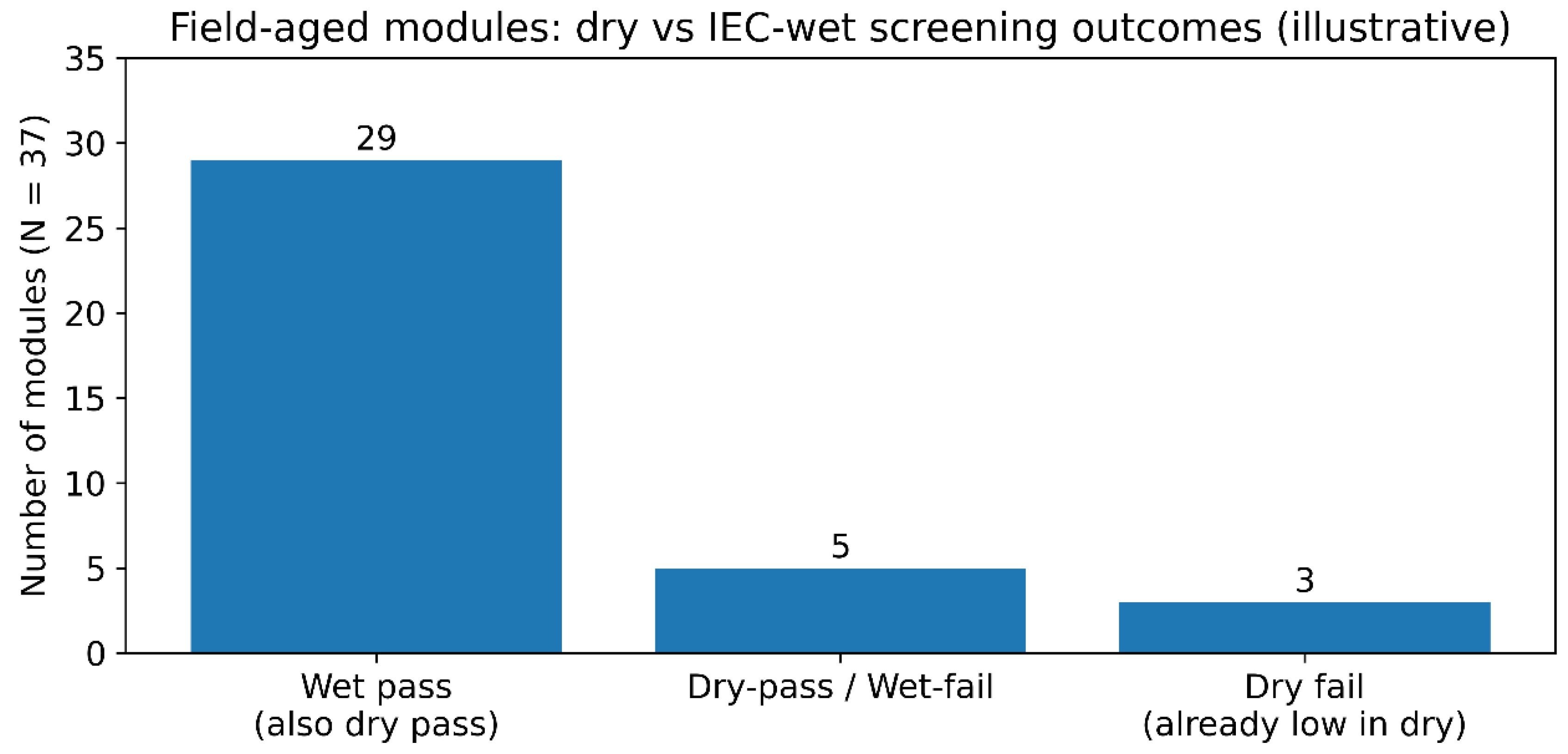
Figure 2.
Sunrise window: wet surfaces coincide with high DC voltage (stylised proxy; supported by [12,13,14]).
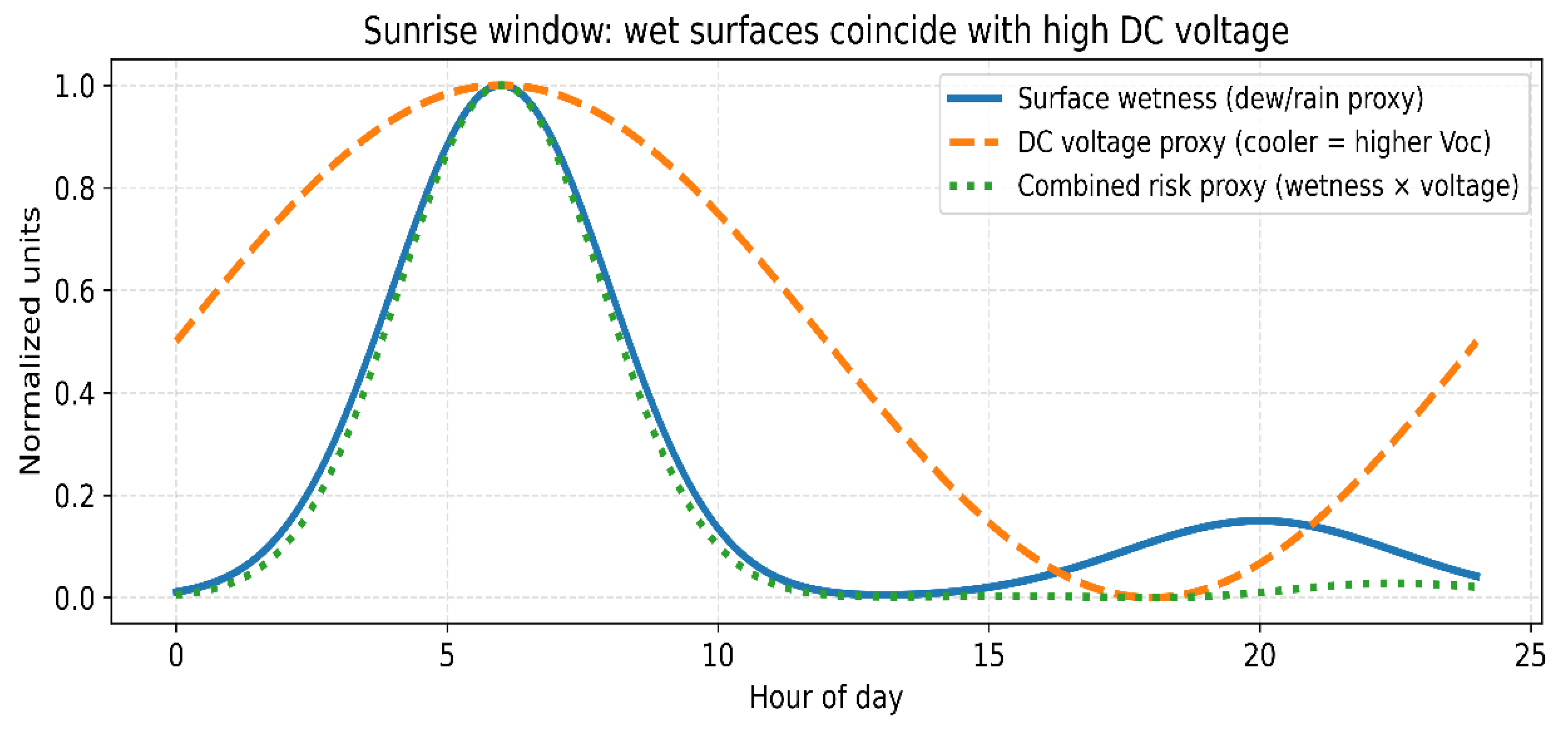
Figure 3.
Failure escalation pathway linking delamination to inverter impacts (schematic; based on [24]).
Figure 3.
Failure escalation pathway linking delamination to inverter impacts (schematic; based on [24]).
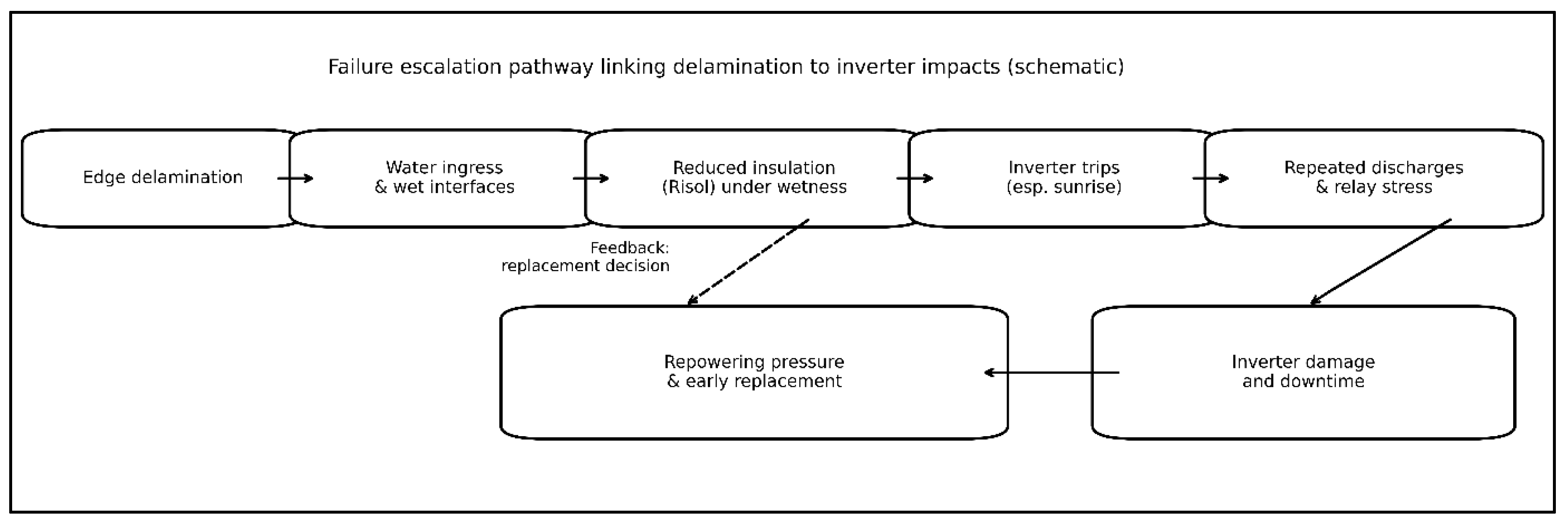
Figure 4.
Illustrative long-term efficiency trend (absolute percentage points; consistent with [4]).
Figure 4.
Illustrative long-term efficiency trend (absolute percentage points; consistent with [4]).
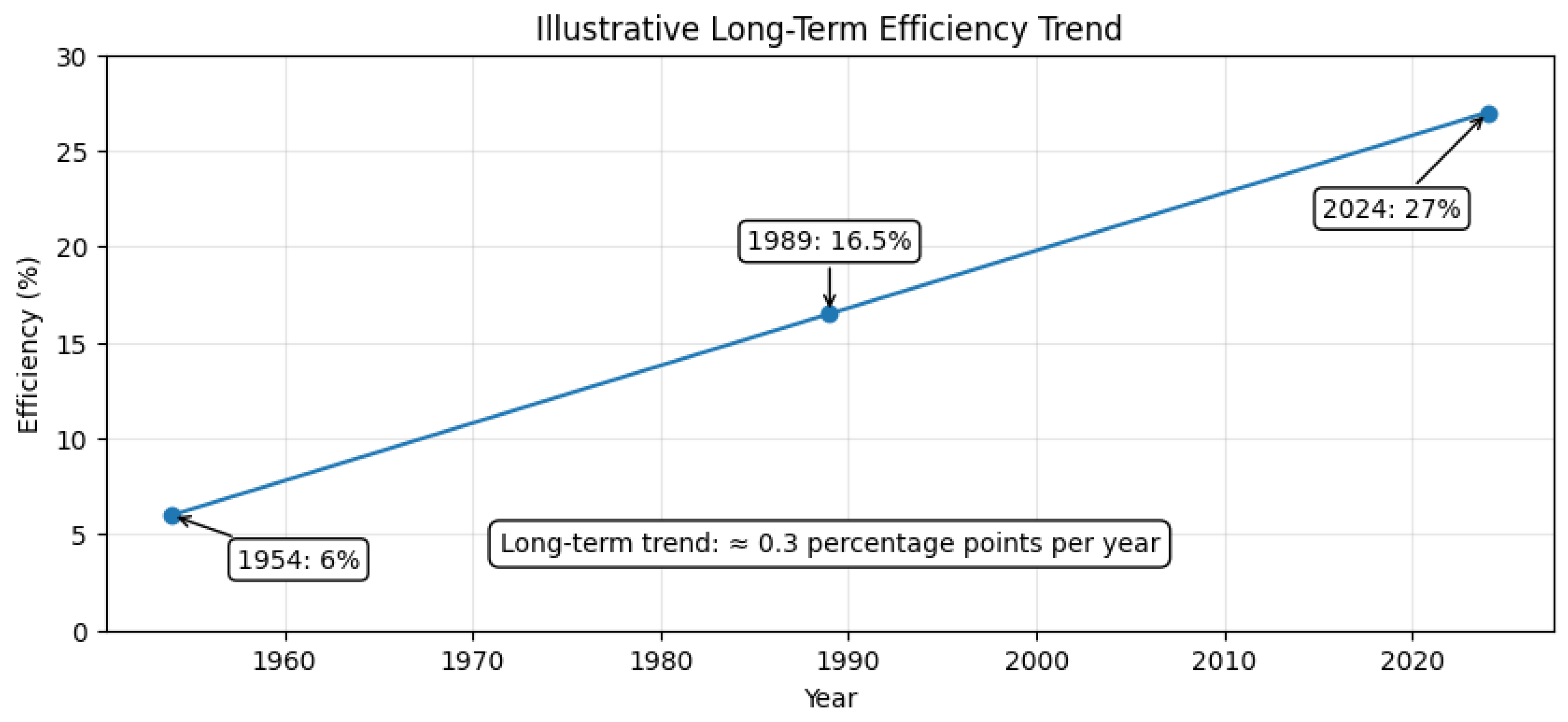
Figure 5.
(a) Stylised Weibull cumulative probability-of-loss curve with the repowering trigger used in S0 (5 years, dashed line). (b) Resulting cumulative waste over 30 years expressed in module-set equivalents (“step” increases at each replacement event) [28].
Figure 5.
(a) Stylised Weibull cumulative probability-of-loss curve with the repowering trigger used in S0 (5 years, dashed line). (b) Resulting cumulative waste over 30 years expressed in module-set equivalents (“step” increases at each replacement event) [28].
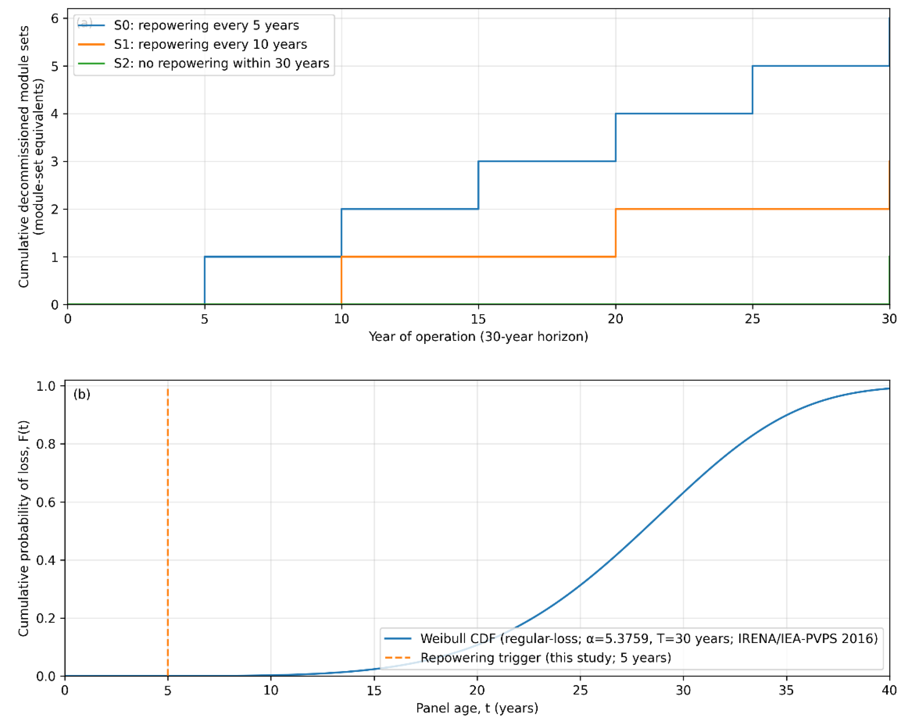
Figure 6.
Manufacturing throughput scales with repowering interval (module sets per 30-year service).
Figure 6.
Manufacturing throughput scales with repowering interval (module sets per 30-year service).
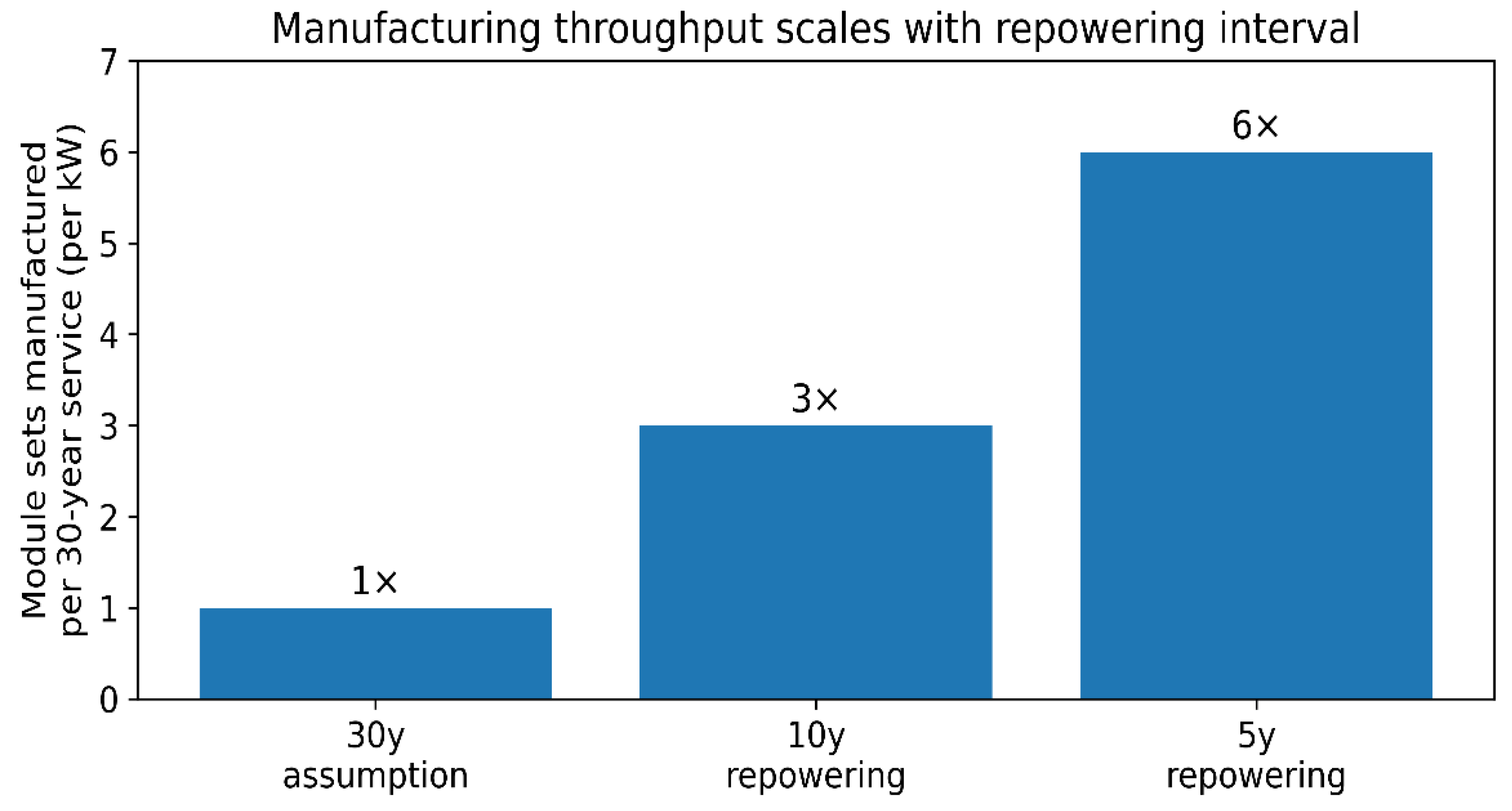
Figure 7.
Short repowering intervals divert manufacturing output from new deployment (stylised illustration).
Figure 7.
Short repowering intervals divert manufacturing output from new deployment (stylised illustration).
Disclaimer/Publisher’s Note: The statements, opinions and data contained in all publications are solely those of the individual author(s) and contributor(s) and not of MDPI and/or the editor(s). MDPI and/or the editor(s) disclaim responsibility for any injury to people or property resulting from any ideas, methods, instructions or products referred to in the content. |
© 2026 by the authors. Licensee MDPI, Basel, Switzerland. This article is an open access article distributed under the terms and conditions of the Creative Commons Attribution (CC BY) license (http://creativecommons.org/licenses/by/4.0/).
Copyright: This open access article is published under a Creative Commons CC BY 4.0 license, which permit the free download, distribution, and reuse, provided that the author and preprint are cited in any reuse.


