
Submitted:
09 February 2026
Posted:
10 February 2026
You are already at the latest version
Abstract
The lack of integrity at the implant-abutment junction (IAJ) contributes to problems such as micromovements and microbial colonization. This study aimed to (1) design a protocol for assessing microleakage at the IAJ using chromophore analysis that hasn’t been involved in other analysis, (2) compare gas and dye leakage using titanium (Ti) and cobalt chrome (CoCr) abutments, and (3) assess the effect of gold (Au) gilding on sealing. Forty abutments were divided into five groups: milled Ti (MTi); cast CoCr (CCoCr); milled CoCr (MCoCr); cast CoCr with Au gilding (CCoCrG); and milled CoCr with Au gilding (MCoCrG). Samples were connected to a pressurised gas and dye reservoir. Chromophore analysis using crystal violet was performed via UV-Vis spec-trometer to calculate leakage concentration. Scanning electron microscopy (SEM) analysis assessed surface morphology which revealed an intimate contact with the MTi and MCoCr but irregularities at the CCoCr abutments. Results showed gas leakage in CCoCr and MCoCr groups, while no true dye leakage occurred in MTi, MCoCr and MCoCrG assemblies. CCoCr exhibited the poorest seal; however, Au gilding improved the seal in these samples. Chromophore analysis using crystal violet provided an ac-curate quantitative assessment. Milled abutments demonstrated significantly less mi-croleakage than cast (non-gilded) versions, Au gilding effectively reduced leakage.
Keywords:
external hexagon implants
; implant abutment junction
; implant-abutment connection
; microgap
; gold gilding
; leakage
1. Introduction
Dental implants offer a reliable solution for replacing missing teeth with high success rates [1,2]. However, the longevity of these restorations depends on a secure and well-fitting connection between the implant and abutment. A microgap at this interface can act as a conduit for bacteria and bacterial by-products, leading to inflammatory reactions, and potential implant failure [3,4,5,6].
Much research has explored various strategies to improve the fit and seal at the implant-abutment junction (IAJ). These include modifications of implant connection geometry [7,8,9], the use of computer-aided design/computer aided manufacture (CAD/CAM) [10], use of different abutment materials [10] and use of sealing agents [11,12].
The abutment material and fabrication method have an impact on the size and behaviour of the microgap. While the lost-wax technique has been a mainstay in dentistry for over a century, it is highly technique-sensitive, relying on the skill of the technician and the quality of the alloy used [13]. In contrast, CAD/CAM technology offers greater precision and consistency, potentially leading to a more uniform and consistent connection between the abutment and the implant, thus to a better fit at the IAJ [14]. Titanium (Ti) and gold (Au) were historically the preferred abutment materials. However, the high cost of Au has led to the development of alternatives such as zirconia (Zi) and cobalt chrome (CoCr), which, in addition to Ti, are now widely used. CoCr has emerged as a viable option due to its affordability and versatility. It can be both cast and milled, making it a flexible choice for implant restorations.
Electrodepositing Au onto the fitting surface of high Au content alloy abutments has been shown to improve the integrity of the IAJ connection under load. A study has demonstrated that this technique can help maintain marginal bone levels over time (12). The ductility of electrodeposited Au facilitates plastic deformation during screw clamping, allowing the abutment to conform more closely to the implant fitting surface. This can help reduce the misfit caused by machining or casting discrepancies, potentially enhancing the sealing of the microgap and improving joint stability[15,16,17].
The misfit at the IAJ is typically documented through measurements under scanning electron microscopy (SEM) of the external perimeter. However, it has been shown that variations in lighting may significantly affect these measurements [15]. In addition, the presence of misfit at the external perimeter of the IAJ may not necessarily be continuous through to the inner portion of the junction. This is in line with findings by Dias et al. [5], in which the microgap is intermittent in their sectioned samples and it is postulated that the microgap has a sinuous or incomplete path through the IAJ. A recent study found that intermittent smearing of a Au layer can create a continuous mosaic around the connecting surface of the abutment, further contributing to the formation of a tight seal [15].
Bacterial microleakage and dye leakage through the IAJ has traditionally been used to assess and compare the IAJ seal of various implant-abutment combinations [11,18,19]. However, bacterial testing is difficult to quantify accurately due to increased experimental complexity and decreased experimental accuracy [20,21]. A chromophore analysis of dye leakage through the IAJ using a UV-Vis spectrometer could improve quantitative measurement and accuracy. Crystal violet would seem an appropriate dye medium. It is extremely stable and non-biodegradable, allowing for analysis to take place over an extended time [22,23].
Given the abutment material and fabrication method have an impact on the size, morphology and seal of the IAJ, the effect of cast versus milled CoCr abutments as well as surface modifications, compared to the traditional Ti abutments requires investigation. The aims of this study were (1) to design a dye transfer protocol for qualitative and quantitative testing of microleakage at the IAJ. (2) To compare the air and dye leakage of milled Ti, milled CoCr and cast CoCr abutments at the IAJ. (3) To compare the air and dye leakage of Au-gilded CoCr abutments (milled and cast) with non-gilded CoCr abutments.
2. Materials and Methods
2.1. Abutment Preparation
A total of 40 abutments were fabricated and equally divided into 5 groups—milled Ti (MTi), cast CoCr (CCoCr), milled CoCr (MCoCr), cast CoCR with Au gilding (CCoCrG), and milled CoCr with Au gilding (MCoCrG). The abutments used had an external hexagon connection, a height of 13mm, and an external diameter of 4mm (Southern Implants, Irene, South Africa).
The 16 MCoCr abutments were fabricated commercially (Southern Implants, Irene, South Africa). The 16 CCoCr abutments were produced using UCLA plastic burnout abutments (Southern Implants, Irene, South Africa) and a high Au content alloy (Auriloy ® Partial, Aurium ® Research U.S.A.) in a commercial laboratory (Sparx Dental, Parramatta, Australia).
2.3. Au Gilding Technique
Electrodepositing Au onto the implant fitting surface of the CoCr abutments proved inconsistent and unreliable. Therefore, a gilding technique was employed. Eight CCoCr and eight MCoCr abutments were cleaned with isopropyl alcohol. A thin coat of oil-based Au size (C.Roberson & Co) was painted onto the abutment fitting surface only and left for 3 hours as per the supplier’s instructions. 24kt Au foil of 12µm thickness was cut into 10x10mm squares and gently placed onto the abutment fitting surface using a bamboo tweezer. Finger pressure was applied to the foil with a sheet of wax paper between. An agate burnisher was then used to burnish the foil to ensure adaptability to the fitting surface. Figure 1 shows a gilded abutment surface after the foil had been placed. Each abutment was assessed and cleaned under a microscope at 20 magnification to ensure no adhesive or foil was present on the internal surface of the abutment.
2.4. Implant-Abutment Assembly (IAA)
The forty abutments were attached to regular platform (4.0mm diameter, 13mm length) external hexagon implants (Southern Implants, Irene, South Africa), held in a bench-mounted vice. Titanium screws (TSHZ2) (Southern Implants, Irene, South Africa) were torqued to 32Ncm following the manufacturer’s instructions using a manual torque control driver and maintained for 5 seconds to ensure reliable reproduction of torque force.
2.5. Microgap Leakage Test
The implant-abutment assemblies (IAAs) were connected to a syringe via non-rigid braided silicone tubing (W&H Aus) (Figure 2a). The tubing was pushed over the abutment by 8mm and into the syringe by 8mm. A layer of paraffin wax sheet was wrapped around the external surface of the abutment to ensure a good seal.
2.5.1. Gas Flow Test
The entire experimental set-up was submerged in a beaker containing 60mL of water, ensuring that the IAJ and rubber tubing connection were submerged (Figure 2b). A gas test was performed for 2 IAAs per group at three different pressures to verify whether the experimental IAAs would stay intact during the duration of the study and to ensure that there was no leakage via the rubber tubing. A 30ml syringe was held vertically by a clamp. The syringe plunger was depressed by 2ml, 6ml and 10ml to generate the 3 different pressures and maintained for 10 minutes. Presence or absence of bubbles at the IAJ was recorded.
2.5.2. Quantitative Dye Leak Test
A serial dilution was performed to create a range of concentrations to establish a calibration curve which was used to determine the concentration of dye released through the IAJ (Figure 3). A starting concentration of 62.5µg/ml crystal violet (Sigma-Aldrich, C.I. 42555; Basic Violet 3) was used and a 1:2 dilution series prepared with water. A plate reader (BMGLabtech CARIOstar Plus) and its proprietary software were used to calibrate and to measure absorption at 590nm.
A similar experimental set-up used for the gas flow test was used for the dye release test. The syringe contained 30ml of a 50 µg/ml crystal violet solution (Sigma-Aldrich, C.I. 42555; Basic Violet 3). The syringe plunger was depressed from 30ml to 24ml and maintained for 10 minutes, which gave an approximate pressure of 126.6kPa. The whole assembly was set up on top of a magnetic stirrer to ensure a more homogenous sampling and prevent the dye from settling.
To evaluate the leakage, a sample of 200µl was taken from the reservoir (60ml) using a pipette (Transferpette®) every minute for 10 minutes and transferred to a 96-well microplate for spectrophotometry analysis (BMG Labech CARIOstar Plus). Dye leak analysis data were used to evaluate the effectiveness of sealing at the implant-abutment junction.
One investigator connected all the IAAs and performed all the laboratory operations under the same conditions to avoid inter-operator variability.
Following spectrophotometry, data integrity was verified by microscopic examination of the microplates and respective wells. Specific data points were excluded from the final analysis if they exhibited anomalous absorbance peaks attributed to identifiable physical artifacts, such as non-dye contaminants, air bubbles, or surface scratched on the base plate, to ensure that the reported values exclusively represented true chromophore concentration.
2.5. Scanning Electron Microscopy (SEM) Examination
The connecting abutment surfaces from each group were assessed prior to implant connection using a scanning electron microscope (SEM)(Phenom XL G2 Desktop SEM, ThermoFisher Scientific, Massachusetts, U.S.A., and JEOL SEM 840, Tokyo, Japan). Two microscopy experts (Institute of Dental Research, Westmead Centre for Oral Health, Westmead, NSW, Australia) (Arto Hardy Family Biomedical Innovation Hub, Chris O’Brien Lifehouse, Camperdown, NSW, Australia) performed the assessments. Once connected, the external perimeters of the IAJs were also assessed.
3. Results
3.1. Presence or Absence of Gas Flow at the Implant-Abutment Junction (IAJ)
3.2. Dye Leak Test
The 40 IAAs were compared for dye leakage. The raw data (optical density [O.D.]) from the plate reader were converted to dye concentrations using the equation developed from the concentration curve (Figure 3). The experimental data and corresponding calculations are graphically represented in Figure 5a–e below.
To ensure the accuracy of the microleakage profiles, all samples underwent a microscopic verification protocol. While initial readings in some Mti and McoCr groups showed elevated values, these were identified as artifacts caused by air bubbles or base-plate irregularities and were subsequently excluded. The refined quantitative data demonstrated that no true dye leakage occurred in the Mti (Group 1), McoCr (Group 2), or McoCrG (Group 4) IAAs over the 10-minute period (Figure 5a,b,d).
There was no true leakage in any of the Mti (Group 1) IAAs (Figure 5a), McoCr (Group 2) IAAs (Figure 5b), and McoCrG (Group 4) IAAs (Figure 5d). The CcoCr IAAs (Group 3) had the poorest seal with the highest dye concentration values (Figure 5c). The addition of Au improved the seal. Five of the 8 CcoCr IAAs (A-E) in Group 3 leaked, but only 2 of the 8 CcoCrG IAAs in Group 5 (G, H) leaked (Figure 5d). Table 4 summarises the results of the number of samples with dye leakages.
3.3. Scanning Electron Microscope (SEM) Examination
SEM images of the abutment connection surface from Groups 1-5 were assessed prior to assembly (Figure 6, Figure 7 and Figure 8). The CcoCr surface (Figure 6c) shows significant irregularities on the surface compared to the Mti and McoCr surfaces (Figure 10a and b). 38 times magnification of random samples of Au gilded surfaces of McoCrG and CcoCrG are shown in Figure 7 and Figure 8.
Once connected, the external perimeter of each of the IAJ microgaps was imaged (Figure 9). The MTi (Group 1) (Figure 9a) and MCoCr (Group 2) (Figure 9b) show intimate contact. The CCoCr (Group 3) show irregularities and a discernible gap at the junction (Figure 9c).
The addition of Au to the abutment appears to have filled the space at these gaps (Figure 10). This reduces the microgap size at the external perimeter, and possibly across the internal aspect of the connection, which correlates to the reduction in dye leakages as depicted in Figure 5c versus 5e.
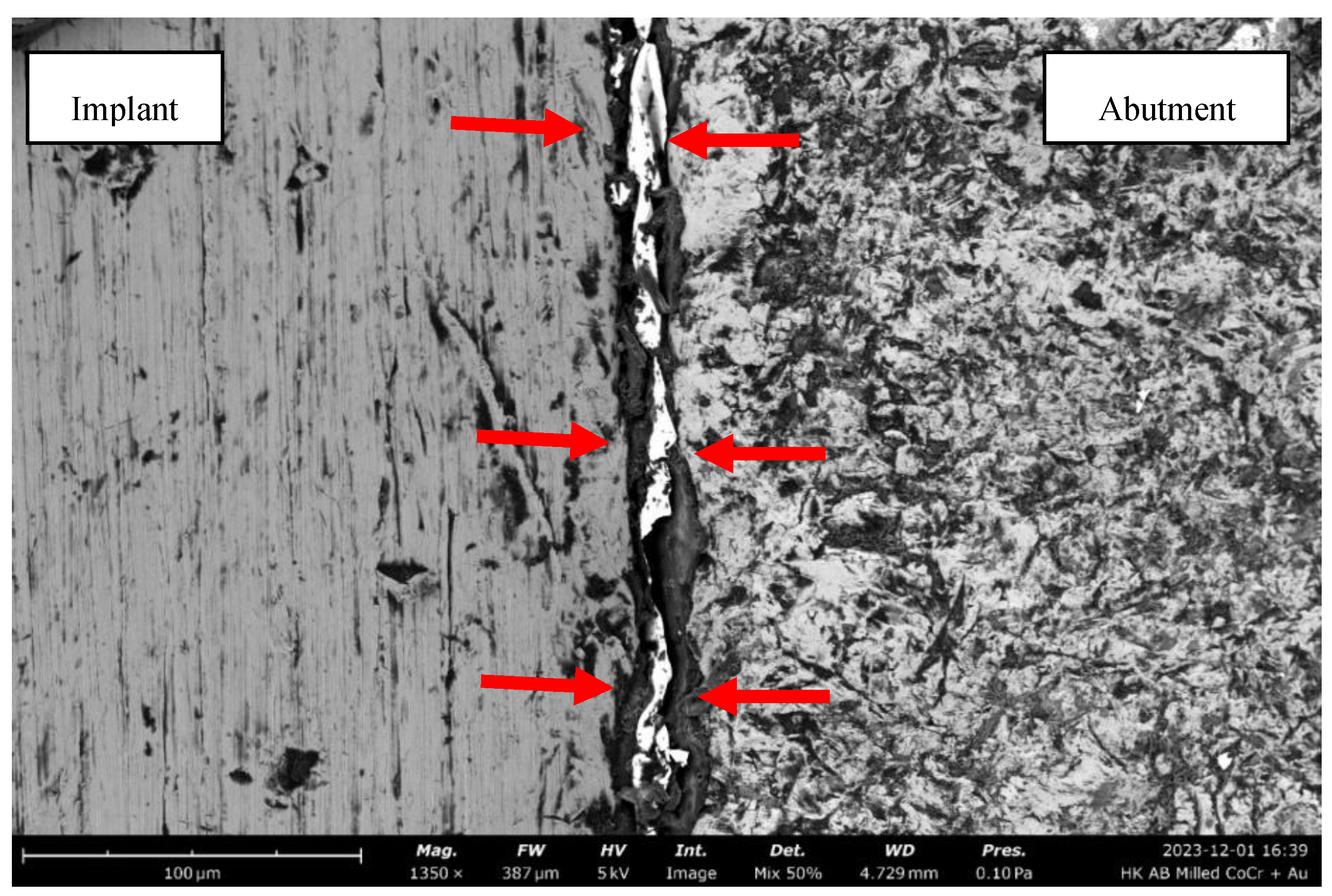
Figure 10.
1350x magnified view of the IAJ of MCoCrG (Group 4 Abutment A) The high-density gold interspersed in the gap is identified by the arrows. Size bar: 100µm.
Figure 10.
1350x magnified view of the IAJ of MCoCrG (Group 4 Abutment A) The high-density gold interspersed in the gap is identified by the arrows. Size bar: 100µm.
After the dye leak test was conducted, the IAAs were disassembled, and surface topography was assessed again and compared to the surface topography before torque application. Figure 11 shows the Au-gilded surface of abutment A from Group 5 before and after torque application. The “white” areas represent the Au layer. The before and after photos show a change in the surface, indicating plastic deformation of the Au with torque application.
4. Discussion
In this in-vitro study, the microleakage of Ti and CoCr abutments, both cast and milled was investigated under static conditions. Cast CoCr showed the most leakage when compared to the other abutments. Milled Ti and milled CoCr abutments with Au gilding did not show any leakage. The Au-gilded cast CoCr abutments showed less leakage compared to the cast CoCr abutments. This study showed that the addition of Au gilding to the abutment surface decreased the leakage.
The use of crystal violet as a staining agent for microleakage evaluation at the IAJ has not been previously described in this context as most studies use methylene blue or bacteria models. Crystal violet, being extremely stable and non-biodegradable, allows for analysis to take place over an extended time [22,23]. This contrasts with methylene blue, which is more susceptible to photodegradation, potentially leading to inaccurate quantitative measurements over long observation periods [24]. While bacterial leakage models are clinically relevant, they are often qualitative outcomes; even when Colony Forming Units (CFUs) are counted, this process is prone to high manual error [20,21]. By utilising a dye-based approach with UV-Vis spectrometer and chromophore analysis, this study eliminates the inherent variability associated with biological growth rates, providing a precise, reproducible assessment of the physical seal at the IAJ.
The pre-test SEMs showed significant irregularities existed at the cast CoCr fitting surface with a larger microgap viewed externally compared to the milled Ti and milled CoCr samples (Figure 9). This is consistent with what is known about a multi-step lost wax casting process in which irregularities are introduced into the geometry at the junction. The casting process is largely dependent on the technician’s skill and the quality of the alloy. These findings were consistent with those of Molinero-Mourelle et al.[10], who found that cast CoCr abutments had more microleakage than milled CoCr abutments. However, not all the cast abutment samples leaked, with 3 out of 8 showing no leakage, highlighting the inconsistencies between the samples and variations in the casting process.
The results of this study have shown that material type and fabrication technique have an impact on the IAJ microleakage. It is widely accepted that milled abutments with fewer surface disparities result in smaller microgaps than cast surfaces [25,26,27]. The results of the current study attest to this with both the milled Ti and milled CoCr IAAs showing the least microleakage.
The addition of Au to the cast abutment connecting surface did reduce the microleakage. Only two of the cast CoCr abutments with Au gilding leaked compared to five of the cast CoCr abutments without Au gilding. The addition of Au at the junction is thought to fill in the voids around the microscopic disparities arising from the casting processes. This is reflected in the reduced leakage detected by the plate reader and is consistent with results obtained in a previous study where cast high-Au content alloys were used [15].
Even though vertical misfit was visible on the cast cobalt chrome with Au gilding, no leakage was detected by the spectrometer for 6 of the 8 samples. This could be because a vertical misfit at the outer edge of the junction may not be continuous from the outer edge to the inner portion of the junction as previously discussed [5]. This is also consistent with a recent study which showed intermittent smearing of the Au layer with potential formation of a continuous mosaic barrier around the connecting surface of the abutment [15] preventing leakage and improving the seal as shown in Figure 15.
The use of external hexagon implants for this study facilitated the ease in the application of the Au layer on to the flat abutment connecting surface. Additionally, the flat surface facilitates visibility under SEM. These factors are difficult with internal connections and for SEM would likely require sectioning. If the seal can be achieved with external hexagon connections, it is likely it can be achieved with internal connections, provided that the abutments can be adequately seated.
The degree of microleakage is a multifactorial condition that is dependent on factors such as precision of fit between the connected componentry, the degree of micromovement between the components, and the amount of clamping force holding the components together.
Micromovement is an important factor because it can facilitate bacterial movement and associated metabolic products across the IAJ, leading to increased concentrations from within the internal screw chamber and mucosal cuff. This is known to initiate a zone of inflammation adjacent to the IAJ, which can lead to both horizontal and vertical bone loss [6] and contribute to future biological and technical complications [28].
This study has several limitations that should be addressed in future research. The primary limitation is the lack of cyclical loading assessment. While our results suggests that the Au glided surface improves the seal, the potential for micromovement under cyclic loading to disrupt or eliminate this gilded layer and affect its sealing capacity over time remains an area of investigation. Additionally, the limited sample size precluded more robust statistical analysis, and the use of a more accurate pressure-controlling apparatus could have influenced the precision of our results.
Within the limitations of the study, it can be concluded:
- The use of chromophore analysis using crystal violet was effective in assessing the quantitative analysis of leakage across the IAJ.
- Microleakage varied and was dependent on the type of abutment and how it was manufactured. Milled Ti and milled CoCr abutments showed significantly less microleakage at the IAJ than cast CoCr abutments.
- The addition of Au to the abutment fitting surface reduces leakage when there is less than an ideal fit at the IAJ.
Author Contributions
Conceptualization, A.B. and T.W.; methodology, A.B. and T.W.; Validation, A.B. and T.W.; formal analysis, A.B. and H.K.; investigation, A.B.; resources, A.B.; data curation, A.B. and H.K.; writing—original draft preparation, A.B. and T.W.; writing—review and editing, A.B. and T.W.; visualization, A.B.; supervision, T.W. and D.H.; project administration, A.B.; funding acquisition, A.B. All authors have read and agreed to the published version of the manuscript.
Funding
This research was financially supported by the Australasian Osseointegration Society (AOS) NSW Branch and the Australian Prosthodontic Society (APS) Federal.
Institutional Review Board Statement
Not applicable.
Informed Consent Statement
Not applicable.
Data Availability Statement
The original contributions presented in this study are included in the article. Further inquiries can be directed to the corresponding author.
Acknowledgments
The authors would like to thank all funders, Jinlong Gao (The University of Sydney), Mara Cvejic (Institute of Dental Research, Westmead Centre for Oral Health), Jeremy Crook and Linda Rogers (Arto Hardy Family Biomedical Innovation Hub, Chris O’Brien Lifehouse) for their assistance in this study. The authors would like to acknowledge Southern Implants for the contribution of implant componentry used in this study.
Conflicts of Interest
The authors declare no conflicts of interest.
Abbreviations
The following abbreviations are used in this manuscript:
| IAJ | Implant-abutment junction |
| IAA | Implant abutment assembly |
| Ti | Titanium |
| Au | Gold |
| CoCr | Cobalt chrome |
| MCoCr | Milled cobalt chrome |
| CCoCr | Cast cobalt chrome |
| MCoCrG | Milled cobalt chrome with gold gilding |
| CCoCrG | Cast cobalt chrome with gold gilding |
| Zi | Zirconia |
| SEM | Scanning electron microscope |
| CAD/CAM | Computer-aided design/computer aided |
References
- Pjetursson BE, Asgeirsson AG, Zwahlen M, Sailer I. Improvements in implant dentistry over the last decade: comparison of survival and complication rates in older and newer publications. Int J Oral Maxillofac Implants. 2014;29 Suppl:308-24. [CrossRef]
- Walton TR. The up-to-14-year survival and complication burden of 256 TiUnite implants supporting one-piece cast abutment/metal-ceramic implant-supported single crowns. Int J Oral Maxillofac Implants. 2016;31(6):1349-58. [CrossRef]
- Ozdiler A, Bakir-Topcuoglu N, Kulekci G, Isik-Ozkol G. Effects of taper angle and sealant agents on bacterial leakage along the implant-abutment interface: an in vitro study under loaded conditions. Int J Oral Maxillofac Implants. 2018;33(5):1071–7. [CrossRef]
- Tripodi D, D’Ercole S, Iaculli F, Piattelli A, Perrotti V, Iezzi G. Degree of bacterial microleakage at the implant-abutment junction in cone morse tapered implants under loaded and unloaded conditions. J Appl Biomater Funct Mater. 2015;13(4):e367-71. [CrossRef]
- Dias EC, Bisognin ED, Harari ND, Machado SJ, da Silva CP, Soares GD, Vidigal GM, Jr. Evaluation of implant-abutment microgap and bacterial leakage in five external-hex implant systems: an in vitro study. Int J Oral Maxillofac Implants. 2012;27(2):346-51.
- Broggini N, McManus LM, Hermann JS, Medina RU, Oates TW, Schenk RK, et al. Persistent acute inflammation at the implant-abutment interface. Journal of Dental Research. 2003;82(3):232-7. [CrossRef]
- Khorshidi H, Raoofi S, Moattari A, Bagheri A, Kalantari MH. In vitro evaluation of bacterial leakage at implant-abutment connection: an 11-degree morse taper compared to a butt joint connection. Int J Biomater. 2016;2016:8527849. [CrossRef]
- Baggi L, Di Girolamo M, Mirisola C, Calcaterra R. Microbiological evaluation of bacterial and mycotic seal in implant systems with different implant-abutment interfaces and closing torque values. Implant Dent. 2013;22(4):344-50. [CrossRef]
- Assenza B, Tripodi D, Scarano A, Perrotti V, Piattelli A, Iezzi G, D’Ercole S. Bacterial leakage in implants with different implant-abutment connections: an in vitro study. J Periodontol. 2012;83(4):491-7. [CrossRef]
- Molinero-Mourelle P, Cascos-Sanchez R, Yilmaz B, Lam W, Pow E, Río J, Gomez-Polo M. Effect of fabrication technique on the microgap of CAD/CAM cobalt-chrome and zirconia abutments on a conical connection implant: an in vitro study. Materials (Basel, Switzerland). 2021;14. [CrossRef]
- Naser Mostofy S, Jalalian E, Valaie N, Mohtashamrad Z, Haeri A, Bitaraf T. Study of the effect of GapSeal on microgap and microleakage in internal hex connection after cyclic loading. Journal of Research in Dental and Maxillofacial Sciences. 2019;4(3):36-42.
- Fernandes PF, Grenho L, Fernandes MH, Sampaio-Fernandes JC, Sousa Gomes P. Microgap and microleakage of a hybrid connection platform-switched implant system in the absence or presence of a silicone-based sealing agent. Odontology. 2022;110(2):231-9. [CrossRef]
- Hunt LB. The long history of lost wax casting. Gold Bulletin. 1980;13(2):63-79. [CrossRef]
- de França DGB, Morais MHST, das Neves FD, Barbosa GAS. Influence of CAD/CAM on the fit accuracy of implant-supported zirconia and cobalt-chromium fixed dental prostheses. The Journal of Prosthetic Dentistry. 2015;113(1):22-8. [CrossRef]
- Walton TR. Effect of electrodeposited gold coatings on micro-gaps, surface profile and bacterial leakage of cast UCLA abutments attached to external hexagon dental implants. Coatings [Internet]. 2023; 13(12). [CrossRef]
- Silva MD, Walton TR, Alrabeah GO, Layton DM, Petridis H. Comparison of corrosion products from implant and various gold-based abutment couplings: The effect of gold plating. J Oral Implantol. 2021;47(5):370-9. [CrossRef]
- Papathanasiou I, Dimitriadi M, Zinelis S. Surface, microstructural, and mechanical characterization of abutment screws with modified surface characteristics. J Esthet Restor Dent. 2025. [CrossRef]
- Berberi A, Tehini G, Rifai K, Bou Nasser Eddine F, El Zein N, Badran B, Akl H. In vitro evaluation of leakage at implant-abutment connection of three implant systems having the same prosthetic interface using rhodamine B. Int J Dent. 2014;2014:351263. [CrossRef]
- D’Ercole S, Dotta TC, Farani MR, Etemadi N, Iezzi G, Comuzzi L, et al. Bacterial microleakage at the implant-abutment interface: an in vitro study. Bioengineering (Basel). 2022;9(7). [CrossRef]
- Trinh KTL, Lee NY. Recent methods for the viability assessment of bacterial pathogens: dvances, challenges, and future perspectives. Pathogens. 2022;11(9):1057. [CrossRef]
- Hombach M, Ochoa C, Maurer FP, Pfiffner T, Böttger EC, Furrer R. Relative contribution of biological variation and technical variables to zone diameter variations of disc diffusion susceptibility testing. Journal of Antimicrobial Chemotherapy. 2016;71(1):141-51. [CrossRef]
- Tian Y, Wu K, Lin S, Shi M, Liu Y, Su X, Islam R. Biodegradation and decolorization of crystal violet dye by cocultivation with fungi and bacteria. ACS Omega. 2024;9(7):7668-78. [CrossRef]
- Kwak SJ, Park J, Sim Y, Choi H, Cho J, Lee Y-M. Biodegradation of crystal violet by newly isolated bacteria. PeerJ. 2024;12:e17442. [CrossRef]
- Ali MA, Maafa IM, Qudsieh IY. Photodegradation of methylene blue using a UV/H2O2 irradiation system. Water. 2024;16(3):453. [CrossRef]
- Byrne D, Houston F, Cleary R, Claffey N. The fit of cast and premachined implant abutments. J Prosthet Dent. 1998;80(2):184-92. [CrossRef]
- Lalithamma JJ, Mallan SA, Murukan PA, Zarina R. A comparative study on microgap of premade abutments and abutments cast in base metal alloys. Journal of Oral Implantology. 2014;40(3):239-49. [CrossRef]
- Molinero-Mourelle P, Roccuzzo A, Yilmaz B, Walter, Pow EHN, Highsmith JDR, Gómez-Polo M. Microleakage assessment of CAD-CAM cobalt-chrome and zirconia abutments on a conical connection dental implant: a comparative in vitro study. Clinical Oral Implants Research. 2022;33(9):945-52. [CrossRef]
- Liu Y, Wang J. Influences of microgap and micromotion of implant-abutment interface on marginal bone loss around implant neck. Arch Oral Biol. 2017;83:153-60. [CrossRef]
Figure 1.
Milled cobalt chrome with gold on the fitting surface.
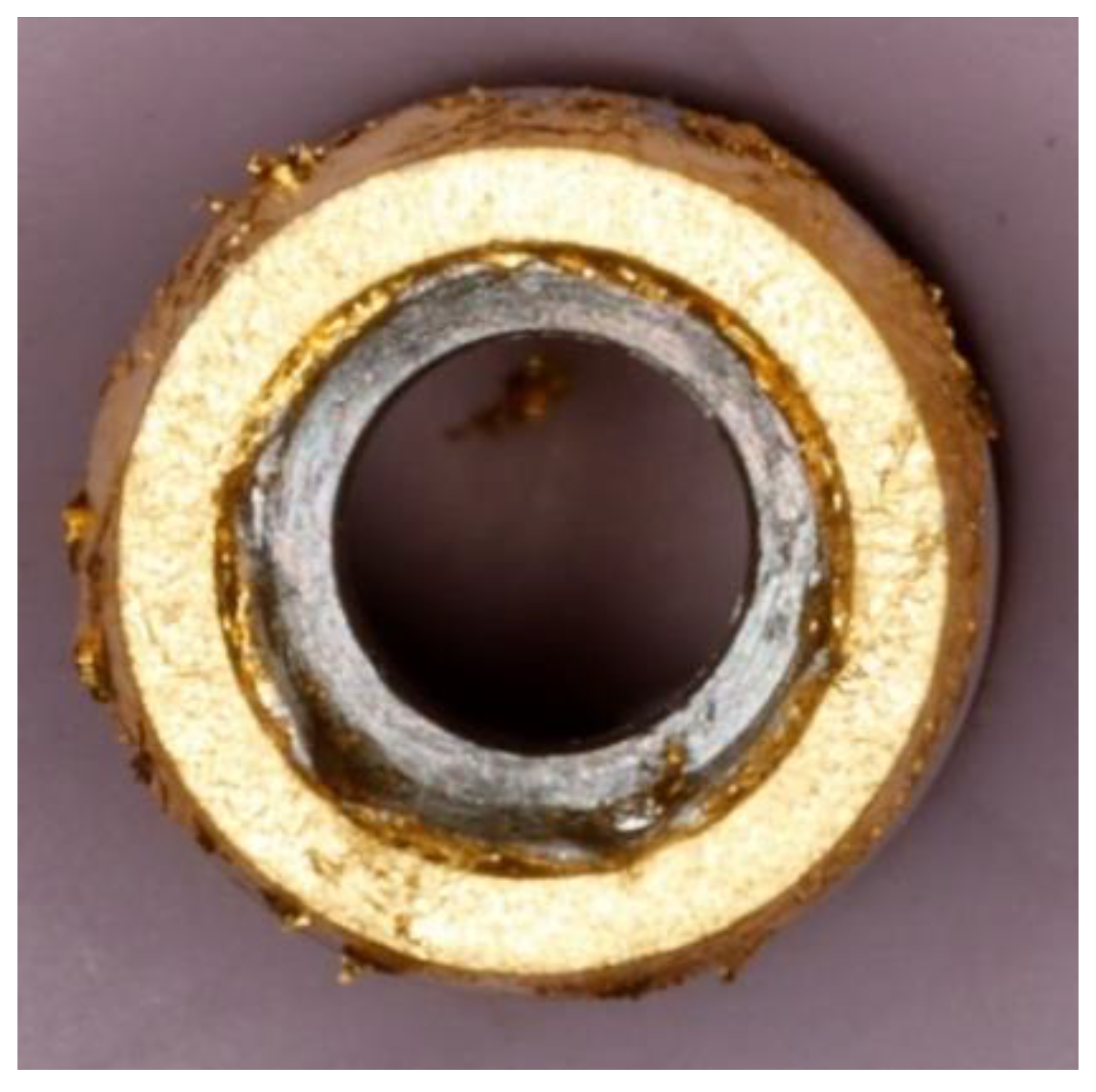
Figure 2.
(a) Assembled components of the experimental setup used in the study; (b) A schematic representation of the set-up. One clamp to hold the syringe and another clamp to hold down the piston of the syringe to the desired level to create a positive pressure. The entire apparatus was placed on top of a magnetic stirrer.
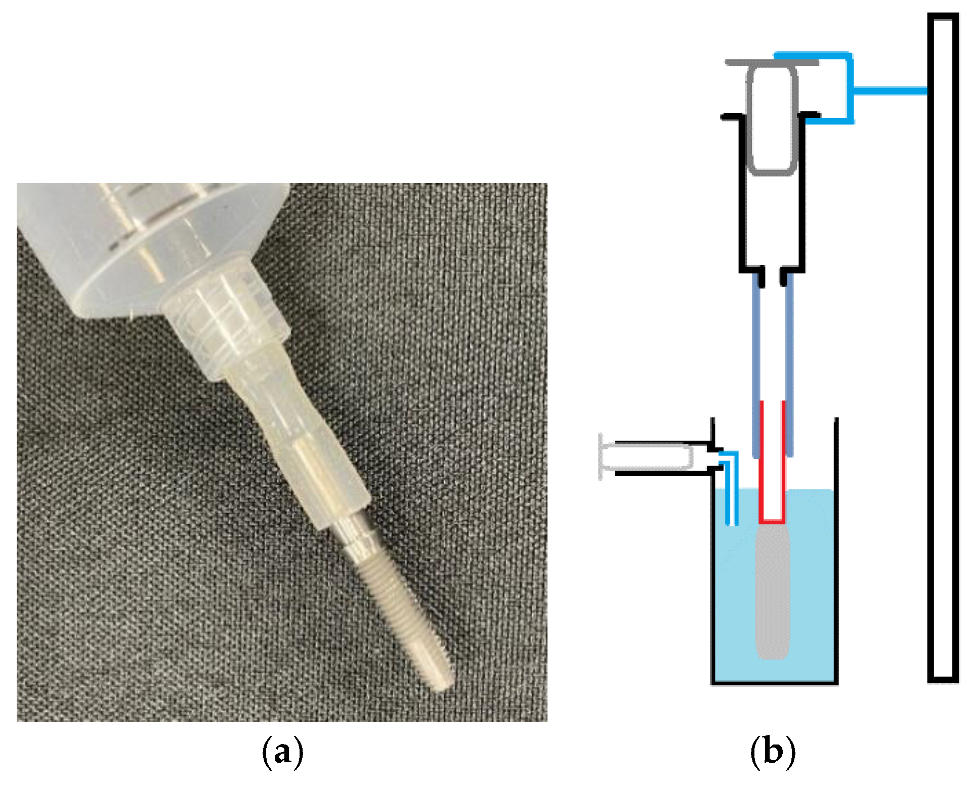
Figure 3.
Calibration curve. Relation between absorbance and concentration.
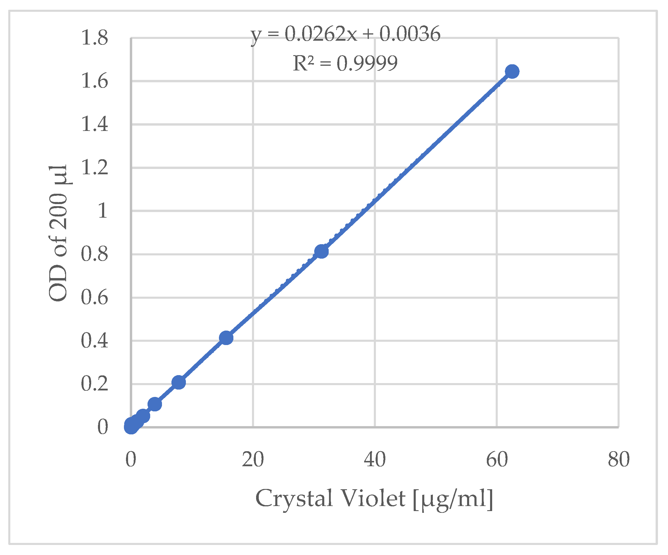
Figure 4.
Gas leakage during testing: (a) Milled cobalt chrome (Group 2) sample A IAA submerged in water with piston pushed down by 10mL. Bubbles are present at the IAJ, indicating gas leakage; (b) Higher magnification view of the IAJ, clearly showing the formation of gas bubbles escaping through the microgap.
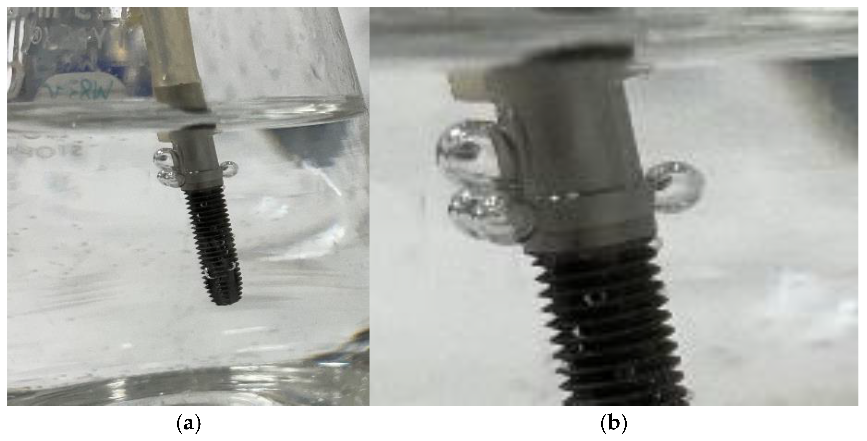
Figure 5.
Graphical representation of crystal violet concentration (µg/ml) detected in the external reservoir over the 10-minute testing period. These graphs depict the quantitative analysis of dye leakage across the IAJ. Each line represents a single sample (A-H) within the respective group. (a) Milled titanium (Mti, Group 1); (b) Milled cobalt chrome (McoCr, Group 2), (c) Cast cobalt chrome (CcoCr, Group 3); (d) Milled cobalt chrome with gold gilding (McoCrG, Group 4); (e) Cast cobalt with gold gilding (CCCoCrG, Group 5). Groups 1, 2, and 4 showed no true leakage, while the non-gilded cast CoCr (c) exhibited the poorest seal. The addition of gold (e) reduced leakage in this group.
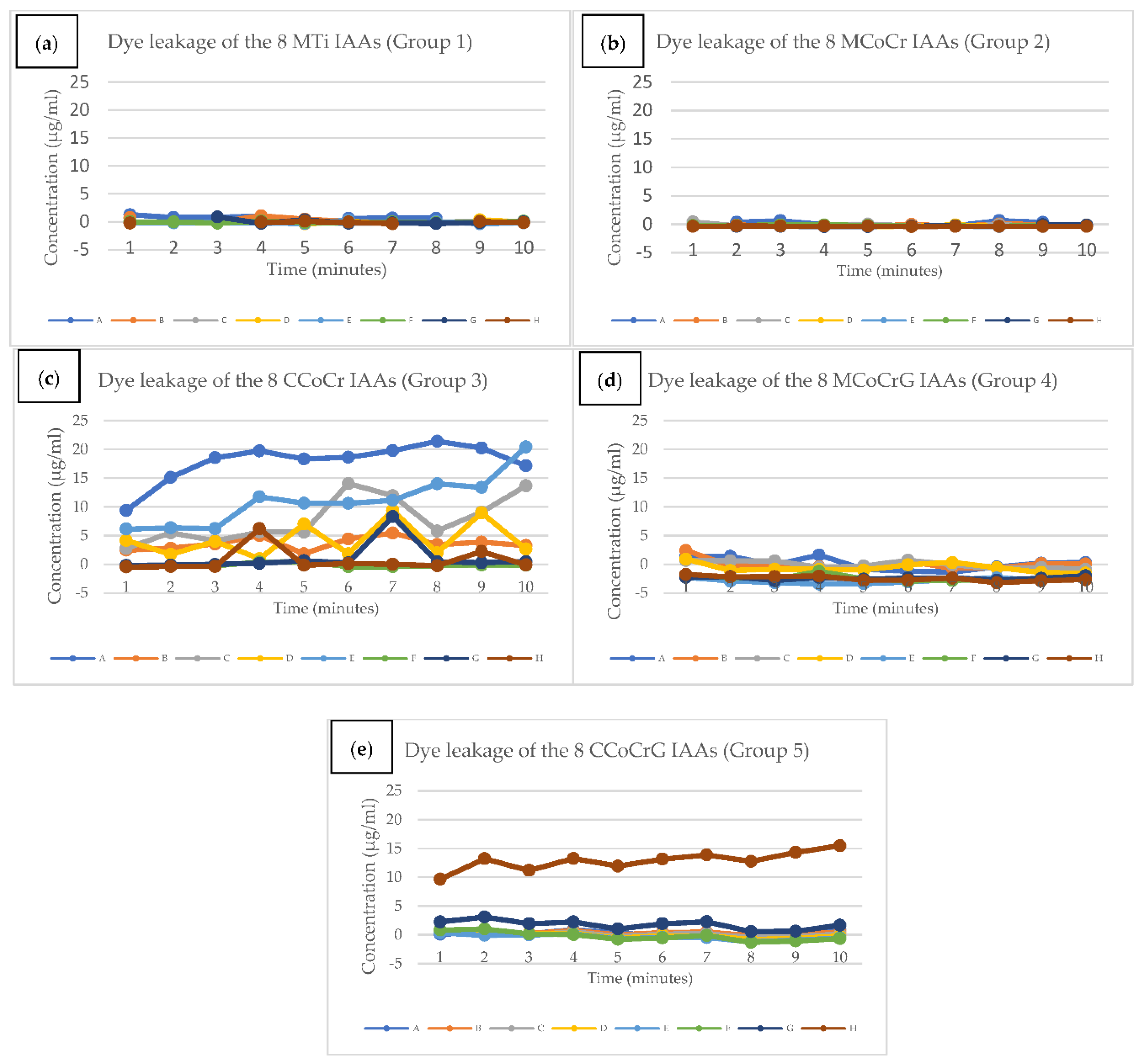
Figure 6.
200x magnification view of abutment connection surface: (a) MTi (Group 1 Abutment A), (b) MCoCr (Group 2 Abutment A) and (c) CCoCr (Group 3 Abutment A). Size bar: 100µm.
Figure 6.
200x magnification view of abutment connection surface: (a) MTi (Group 1 Abutment A), (b) MCoCr (Group 2 Abutment A) and (c) CCoCr (Group 3 Abutment A). Size bar: 100µm.
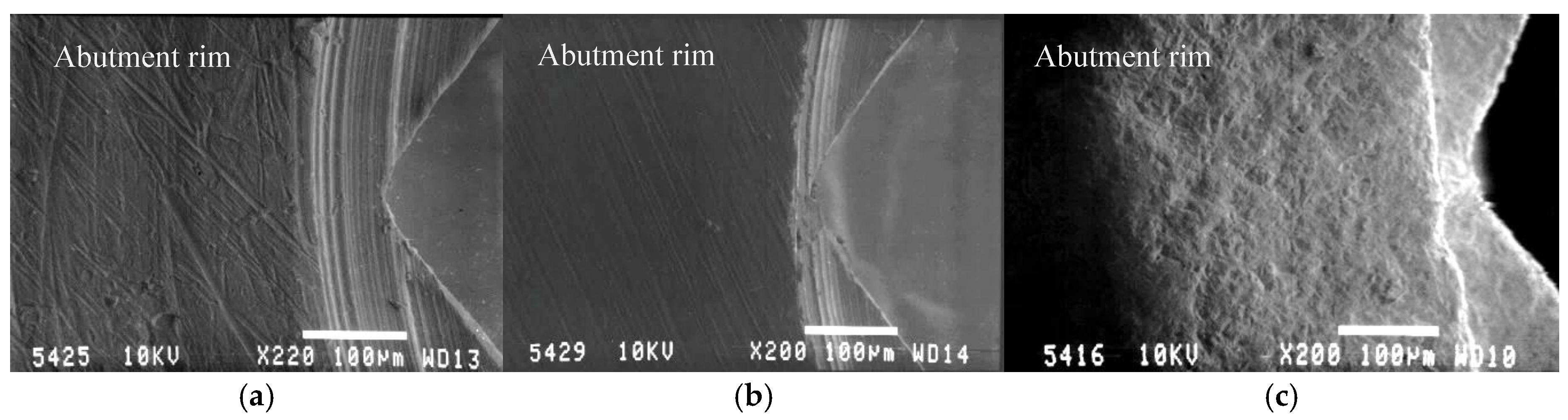
Figure 7.
38x magnification of MCoCrG (Group 4) abutment connection surfaces, (a) Abutment A, (b) Abutment B, (c) Abutment C. Size bar: 3mm.
Figure 7.
38x magnification of MCoCrG (Group 4) abutment connection surfaces, (a) Abutment A, (b) Abutment B, (c) Abutment C. Size bar: 3mm.
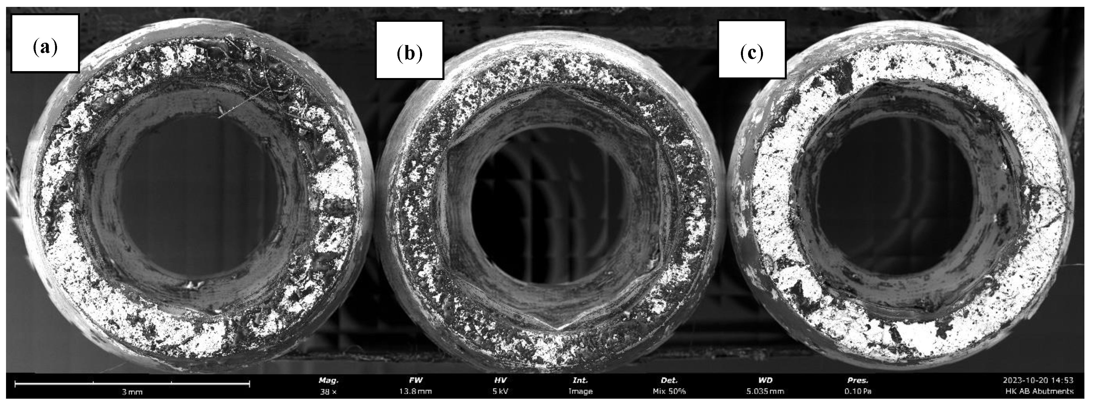
Figure 8.
34x magnification of CCoCrG (Group 5) abutment connection surfaces, (a) Abutment A, (b) Abutment B, (c) Abutment C. Size bar: 3mm.
Figure 8.
34x magnification of CCoCrG (Group 5) abutment connection surfaces, (a) Abutment A, (b) Abutment B, (c) Abutment C. Size bar: 3mm.
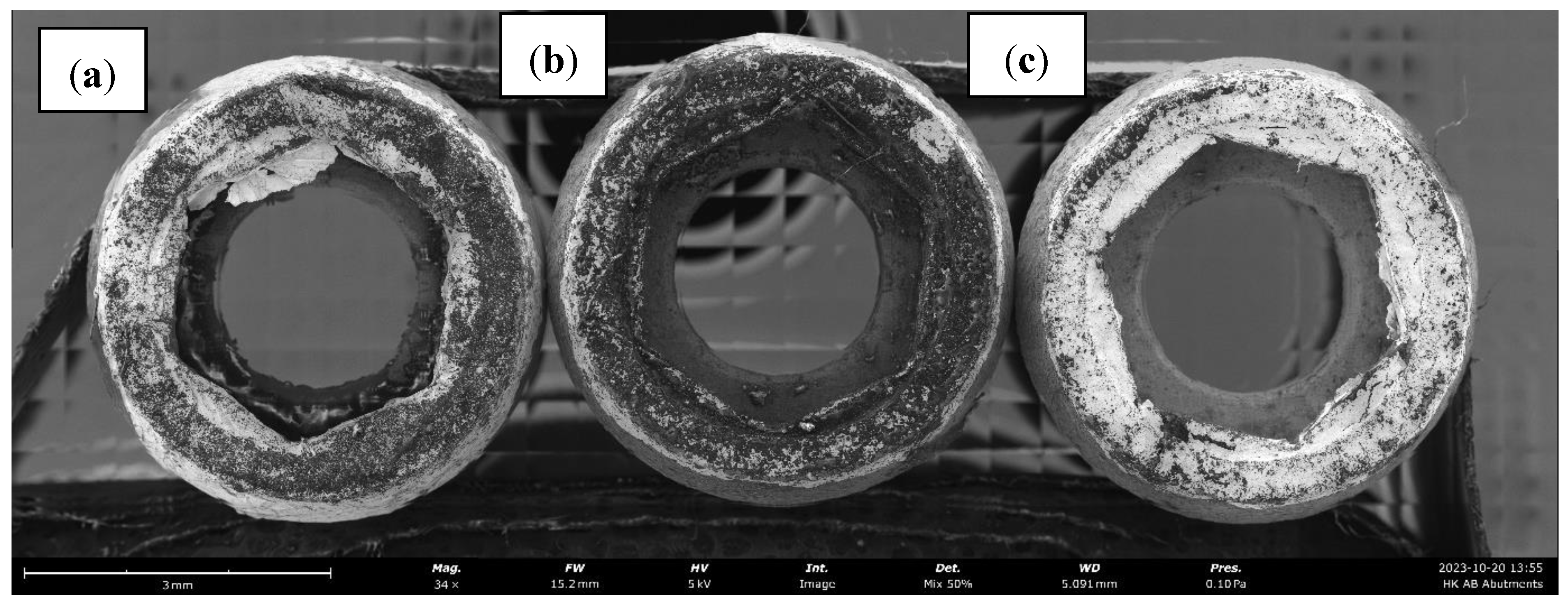
Figure 9.
200x magnified view of IAJ of, (a) MTi (Group 1 Abutment A); (b) MCoCr (Group 2 Abutment A) and (c) CCoCr (Group 3 Abutment A). The IAJ is identified by the arrows.
Figure 9.
200x magnified view of IAJ of, (a) MTi (Group 1 Abutment A); (b) MCoCr (Group 2 Abutment A) and (c) CCoCr (Group 3 Abutment A). The IAJ is identified by the arrows.
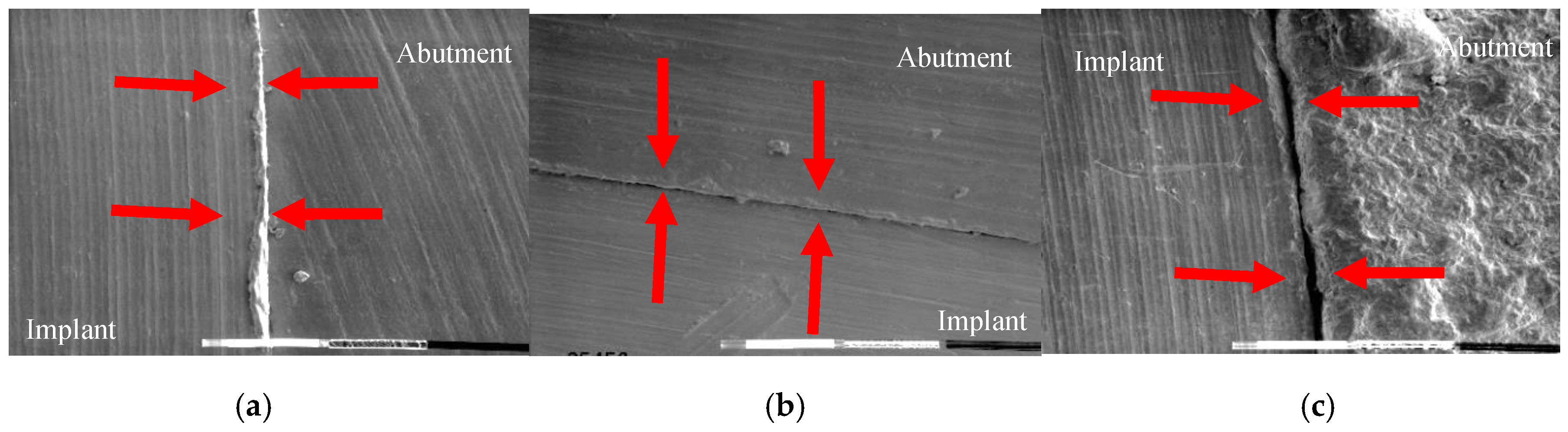
Figure 11.
SEM images of the CCoCrG, group 5 abutment connection surface (Magnification 630x) showing deformation of the gold leaf. (a) View of the abutment rum before torque application; (b) View of the same area after torque application. The images highlight the physical change and deformation of the gold layer (encircled area) upon assembly, which is indicative of plastic deformation and filling of microgaps. Size bar: 200µm.
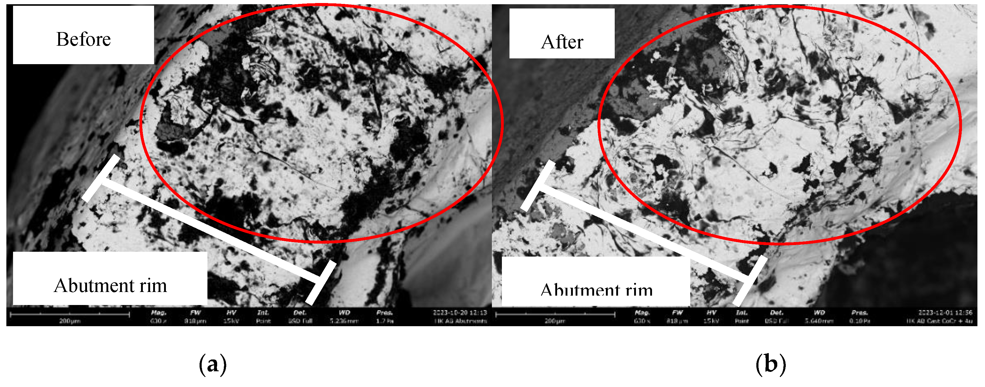

Table 1.
Castable abutment composition.
| Element | Percentage (%) |
| Cobalt (Co) | 67 |
| Chrome (Cr) | 28 |
| Molybdenum (Mo) | 5 |
| Carbon (C) | <1 |
| Silicon (Si) | <1 |
| Manganese (Mn) | <1 |
| Iron (Fe) | <1 |
| Nitrogen (N) | <1 |
Table 2.
Summary of studied abutment types.
| Group | Sample size | Abutment Material | Manufacturer |
| 1 | 8 | Milled Ti (MTi) | Southern Implants |
| 2 | 8 | Milled CoCr (MCoCr) | Southern Implants |
| 3 | 8 | Cast Cocr (CCoCr) | Sparx Dental Lab using UCLA plastic abutments supplied by Southern Implants |
| 4 | 8 | Milled CoCr with Au gilding (MCoCrG) | Southern Implants Gold gilding by 1 investigator |
| 5 | 8 | Cast CoCr with Au gilding (CCoCrG) | Sparx Dental Lab using UCLA plastic abutments supplied by Southern Implants Gold gilding by 1 investigator |
Table 3.
Results of the gas test.
| Mti | McoCr | CcoCr | McoCrG | CcoCrG | ||||||
| Sample Piston level |
A | B | A | B | A | B | A | B | A | B |
| 28mL | No | No | No | No | No | No | No | No | No | No |
| 24mL | No | No | No | No | Yes | Yes | No | No | No | No |
| 20mL | No | No | Yes | No | Yes | Yes | No | No | No | No |
Yes/No indicate presence of bubbles at the microgap.
Table 4.
Summary of results of dye test.
| Group | Abutment | Number of samples with dye (assumed) leakages |
| 1 | Mti | 0/8 |
| 2 | McoCr | 0/8 |
| 3 | CcoCr | 5/8 |
| 4 | McoCrG | 0/8 |
| 5 | CcoCrG | 2/8 |
Disclaimer/Publisher’s Note: The statements, opinions and data contained in all publications are solely those of the individual author(s) and contributor(s) and not of MDPI and/or the editor(s). MDPI and/or the editor(s) disclaim responsibility for any injury to people or property resulting from any ideas, methods, instructions or products referred to in the content. |
© 2026 by the authors. Licensee MDPI, Basel, Switzerland. This article is an open access article distributed under the terms and conditions of the Creative Commons Attribution (CC BY) license (http://creativecommons.org/licenses/by/4.0/).
Copyright: This open access article is published under a Creative Commons CC BY 4.0 license, which permit the free download, distribution, and reuse, provided that the author and preprint are cited in any reuse.


