
Submitted:
06 February 2026
Posted:
10 February 2026
You are already at the latest version
Abstract
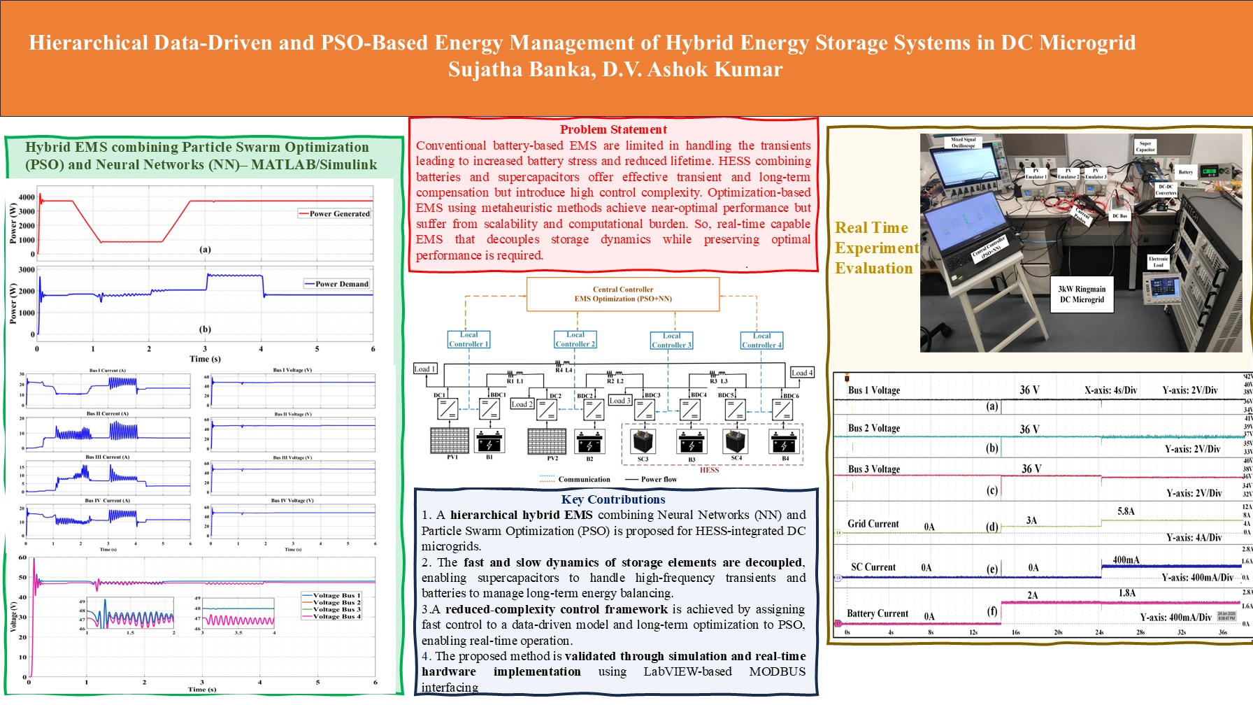
In the era of renewable dominated grids and integration of dynamic load such as EV charging stations has increased the operational challenges in multifolds particularly in DC microgrids (DC MG). Traditional battery dominated grid’s energy management strategies (EMS) are often not capable of handling fast transients due to limitations of battery electrochemistry. To overcome this limitation, an hierarchical hybrid energy management strategy is proposed that uses the combination of data driven and metaheuristic algorithms. The designed optimization framework consists of particle swarm optimization (PSO) and neural network (NN) implemented in central controller of 4 bus ringmain DC MG. A efficient decoupling of fast and slow storage dynamics is performed, where supercapacitor (SC) is optimized using NN and battery is optimized using PSO. This selective optimization reduces the computational overhead on the PSO making it more feasible for realtime implementation. The designed hybrid PSO-Neural EMS framework is initially designed on MATLAB and further validated on realtime hardware setup. Robustness of the control scheme is verified with various case studies such as, renewable intermittency, dynamic loading and partial shading scenarios. An effective optimization of SC in both transient and heavy load scenarios is observed. LabVIEW interfacing is used for MODBUS based interaction with PV emulators and DC-DC converters.
Keywords:
DC microgrids
; hierarchical control
; neural network
; particle swarm optimization
; hybrid energy storage systems
; supercapacitor
1. Introduction
Decentralised DC MG architectures gained popularity with the increased adoption of renewable energy resources, electric vehicle and extensive use of power electronic devices for load interfacing [1]. Also, DC MG will provide the unique advantages over AC especially in renewable dominated grid such as seamless integration with RES, improved power quality and reduced power conversion stages [2]. Apart from these advantages DC MGs face control challenges during renewable intermittency, highly stochastic and dynamically varying loads. These uncertainties lead to power imbalances, poor voltage regulation and non uniform load sharing [3]. Therefore to achieve the reliable and resilient control of DC MG, adaptive power balance mechanism should be implemented that can address both transient conditions and long-term energy variations.Battery energy storage system (BESS) are the most prominent technology employed due to its high energy density and matured technology [4]. But BESS performance is limited by its characteristic of slow dynamic response, also they suffer accelerated aging when subjected to frequent transient operations [5]. Therefore, sole dependency on the BESS for the power compensation in renewable dominated grid results in reduced aging, excessive thermal stress and reduced operational reliability. Overcoming these limitations of BESS, SC is combined with BESS to make it a hybrid energy storage system (HESS) [6]. High power density of the SC will make it best choice for the transient operations, thereby reducing the burden on the BESS. By utilizing the complimentary characteristics of battery and SC, better voltage regulation and power optimizing can be achieved. Apart, from all these advantages, the coordinated control during high frequency operations become challenging task. State of charge constraints, non linear storage dynamics, high intermittency and variable load demand complicate the control strategy. Therefore, developing, scalable, reliable and robust HESS control strategy becomes crucial for optimized operation of DC MG.
1.1. Problem Statement
When BESS are solely made responsible to tackle with the rapid changing load dynamics such as EV charging stations, fast and recurrent power fluctuations they experience severe operational stress. Inherent electro chemical properties of the BESS will always not guarantee the better transient performance. Therefore, parallel operation of BESS and SC will be the solution for better performance in both transient and long term compensations [7]. But including these combination and making it HESS will increase the control design complexity. Therefore there is need to develop an control logic that obtains the tradeoff between design complexity and DC MG performance. Classical optimization techniques that implement energy management strategies, especially metaheuristic methods like PSO will achieve near optimal solution [8]. But, as the size of the grid increases, these solutions will face scalability issues thereby increasing the complexity of the optimization problem. This significantly reduce the real time applicability. Therefore, it is trivial to design an advanced control technique that preserves the benefits of the optimal energy management while reducing the computational overhead. This will enable real time operation of HESS in DC MG environment.
1.2. Literature Review
A large body of work has investigated control and energy management strategies for HESS in DC MGs. Conventional approaches typically employ rule-based or droop-based strategies to coordinate power sharing between BESS and SCs [9,10]. In such schemes, the SC is often controlled to respond to high-frequency components of the load or RES power, while the battery compensates for low-frequency variations and steady-state imbalances. Although these methods are simple and easy to implement, they are usually tuned heuristically, may not account for detailed storage dynamics and constraints, and can struggle to maintain optimality under highly variable conditions. To improve performance, optimization-based EMS have been proposed, formulating HESS operation as a constrained optimization problem that accounts for converter limits, state-of-charge (SoC) constraints, power ratings, efficiency, and battery aging considerations [11,12]. Metaheuristic algorithms such as PSO, Genetic Algorithms, and other evolutionary techniques are widely utilized due to their flexibility and ability to handle nonlinear, nonconvex problems and mixed-integer decision variables [13]. These methods have shown the capability to achieve near-optimal power-sharing decisions for a variety of operating scenarios and objective functions, such as loss minimization, cost reduction, and lifetime extension. However, because metaheuristics perform iterative searches over large and often high-dimensional solution spaces, their computational burden grows significantly with system size, number of storage units, and the richness of constraints. As a consequence, many reported EMS solutions operate with relatively long control horizons and coarse time steps, which limits their applicability for fast, real-time control during transient events in dynamic DC MGs [14].
In parallel with optimization-based methods, data-driven and advanced control techniques have been explored for HESS and DC MGs. Model predictive control (MPC) and robust control schemes have been proposed to handle constraints and uncertainties explicitly while providing improved dynamic performance. However, MPC formulations for HESS often involve solving optimization problems online, which again raises concerns regarding computational tractability in fast timescales and under high dimensionality. More recently, machine learning and other data-driven approaches have been investigated to approximate optimal control laws or to perform state and disturbance prediction [15]. Techniques such as neural networks, fuzzy logic controllers, and reinforcement learning have been applied to emulate or learn optimal power-sharing patterns between BESS and SCs under varying operating conditions. These data-driven strategies can offer fast inference once trained, making them attractive for real-time deployment. Nevertheless, they typically require extensive and representative training data, and their performance may degrade when confronted with operating conditions not well captured during training. Furthermore, when used in isolation, purely data-driven schemes may not directly enforce physical constraints, such as SoC limits and power ratings, or may lack explicit mechanisms to optimize long-term objectives like battery lifetime and energy efficiency. Consequently, there is a growing interest in hybrid approaches that combine the adaptability and speed of data-driven models with the rigor and global perspective of optimization-based methodologies [16,17]. Despite significant progress, several limitations remain in existing HESS control and EMS strategies for DC microgrids. First, many optimization-based frameworks treat the HESS as a single decision block, jointly optimizing BESS and supercapacitor setpoints using a unified metaheuristic or centralized optimizer. While this can produce high-quality solutions, it leads to large decision spaces and high computational complexity, especially when multiple storage units, diverse operating modes, and detailed constraints are considered [18]. This complexity inhibits real-time applicability during fast transient events, where rapid decisions are required on the order of milliseconds to seconds [19]. Second, existing methods often do not explicitly decouple the fast and slow dynamics of HESS in a manner that is systematically reflected in the control architecture. In practical DC MGs, SCs are naturally suited for high-frequency transient compensation, whereas batteries target slower energy balancing [20]. However, many EMS designs either use simplified filters or heuristics to distinguish time scales or rely on joint optimization, without exploiting a structured decomposition of the control problem. This can lead to redundant computations, delayed responses to disturbances, and suboptimal use of storage resources, particularly under highly stochastic RES and EV loading conditions. Third, data-driven approaches proposed for HESS control usually aim either to replace the optimization layer or to provide predictive information, but they rarely operate in a tightly integrated, hierarchical manner with metaheuristic or other optimization-based EMS. As a result, they may not fully leverage their capacity for fast real-time decisions while still benefiting from systematic long-term optimization. There is a lack of frameworks that strategically allocate fast control actions to a data-driven layer and reserve slower, more computationally intensive optimization for long-term scheduling, in order to balance responsiveness and optimality. These limitations highlight a clear research gap: the need for control frameworks that explicitly separate fast and slow HESS dynamics, reduce the effective dimensionality of the optimization problem, and retain both real-time responsiveness and near-optimal energy management.
1.3. Novelty
The central contribution of the work is to utilize the combination of data driven and meta heuristic methods for design of hybrid energy management framework. Unlike the classical optimization techniques that jointly combines BESS and SC in a single framework making it computationally intensive metaheuristic algorithm, the proposed framework adopts selective and hierarchical control philosophy. SC power allocation is optimized by the data driven technique ensuring the effective suppression of power transients. In contrast, BESS uses PSO based optimization to address long term compensation. This decoupling allows effective SC compensation, as it uses advanced and non linear data driven techniques. Also, the complexity of the control reduces as the light weight PSO algorithm is used for BESS optimization. This significantly reduces the dimensionality of the optimization problem and the computational burden. This design is well suited for real time implementation in dynamically varying load conditions and renewable dominated DC MGs.
1.4. Key Contributions
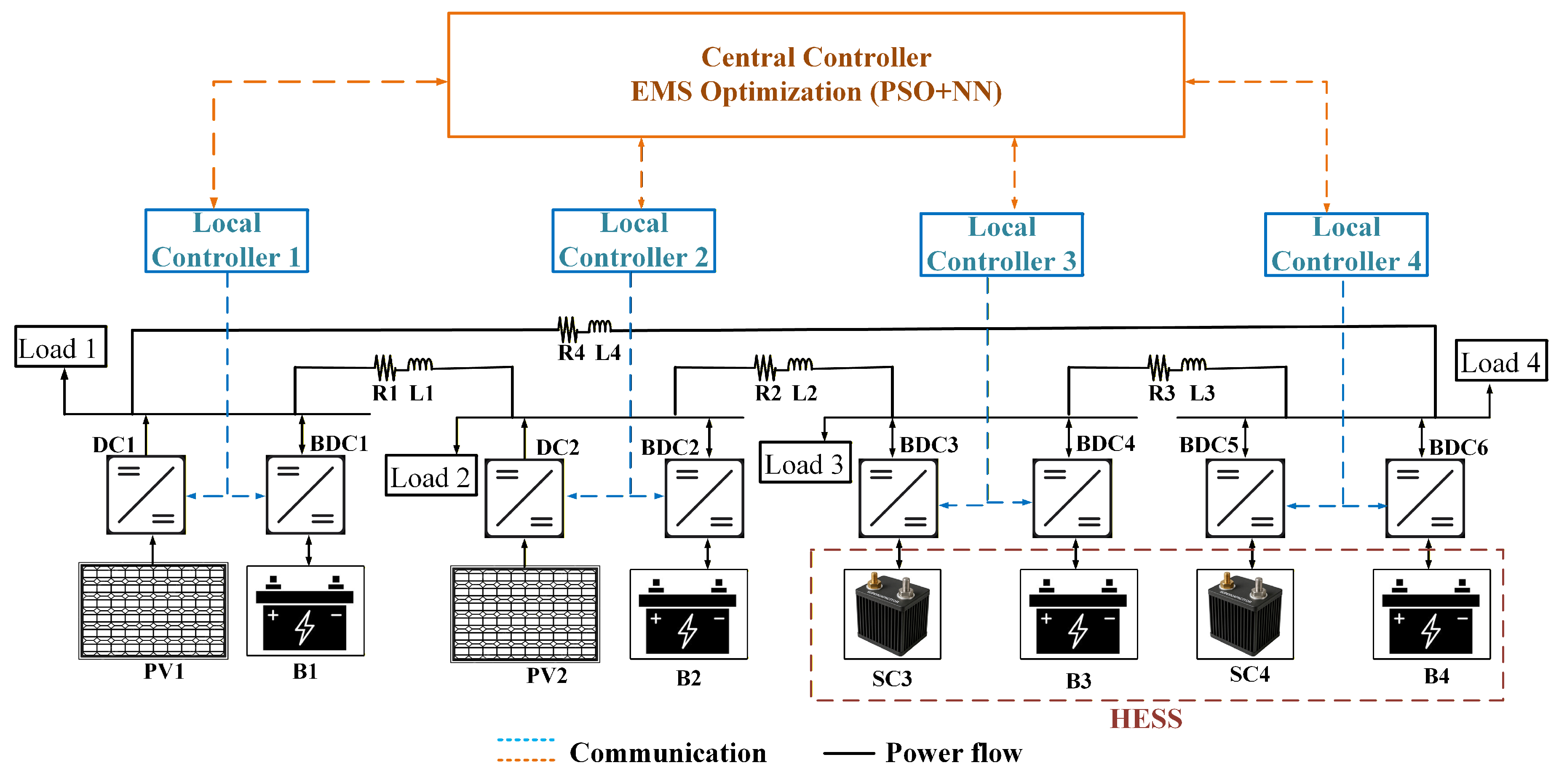
Figure 1.
4 Bus ring main DC MG architecture.
1.5. Organization
The paper is organized as follows: Section II details the methodology which discusses about system description, hybrid PSO-Neural EMS architecture and NN training procedure. Results for the proposed framework is implemented in section III, which analysis the simulation and real-time implementation. Article concludes with Section IV conclusion, which summarizes the contributions of the work and discusses about the future scope.
2. Methodology
2.1. System Description
The work considers the 4 Bus ring main distributed DC microgrid system designed with hierarchical control methodology. The detailed architecture of the microgrid is presented in Figure 1. 4 nodes are considered in the design, where node 1 and node 2 has the combination of PV and battery storage system. Where as node 3 and node 4 has hybrid energy storage system (HESS) of battery and super capacitor. Therefore the combination of DER and HESS will emulate the practical microgrid conditions. and are the PV arrays considered at node 1 and node 2 respectively. and are the local battery storage near the node 1 and node 2 respectively. These DER and battery are connected to the DC Bus with the power electronic converters, DC-DC converter (MPPT) for PV are denoted with and , the charging and discharging of the battery is carried out with bidirectional DC-DC converter indicated with and . SC and battery storages in node 3 and node 4 are represented as , , and respectively. Similarly, the converters used here are labeled as and for SC and and for battery storage. , , and are the loads connected at each node. The transmission line impedance for each bus connection is represented with R-L combination. The impedance parameters between node 1-2, 2-3,3-4 and 4-1 are indicated as , , and respectively. There are 2 levels of communication (Local communication and Central communication) above the power circuit as indicated in Figure 1. In the hierarchical control strategy, the local controller () is responsible for controlling the individual nodes, whereas the central controller is tasked with the EMS and optimization responsibilities. , , and will control the PEC of node 1,2 3 and 4 respectively. Central controller receives the information from LC’s and optimizes the operation of battery and SC in the system.
2.2. Hybrid PSO–Neural EMS Architecture
In the design of Hybrid EMS strategy, the objectives that are considered are as follows: 1) Maintaining the voltage regulation at each bus 2) Satisfying the instantaneous power balance between DER, HESS and loads 3) Reducing the battery stress by optimizing its operation 4) Optimal utilization of Super capacitor for high frequency compensation.
Power balance constraint of DC microgrid is expressed as (1). indicates the overall power generated from PV sources, . () is the instantaneous battery contribution. Similarly, () is the instantaneous super capacitor contribution.
At each control instant, the hybrid EMS receives the input u(t) as shown in (2). The input vector contains the consolidated information of different powers and the SoC’s of battery and SC. These also, represent the electrical operating state of the DC bus and the energy availability of the storage systems. Hybrid EMS outputs the reference current commands for battery and supercapacitor and the state of operation for HESS as shown in (3) and (4).
Here, the dimensionality of the output vectors, and depends on the number of storage elements involved. As there are 4 battery and 2 SC in our system, the dimension of and will be and respectively.
In traditional PSO-based EMS formulations, both battery and supercapacitor power references are optimized simultaneously. This increases the dimensionality of the search space, resulting in slower convergence, higher computational burden and reduced real-time feasibility. To overcome these limitations, the proposed EMS adopts a hybrid PSO–Neural (PSO-NN) structure. Here, battery power references are optimized using PSO and SC power references are predicted using a neural mapping. This decoupling exploits the natural roles of the storage devices: the battery handles low-frequency energy balancing, while the SC compensates fast power transients.
2.3. Design of PSO-NN EMS
Particles in the PSO are defined with the battery power dispatch variables as shown in (5). Where and is the total number of particles. Velocity update equation and the particle position update equation are given in (6) and (7).
Here, , and represents inertia weights and cognitive and social acceleration coefficients respectively. , are considered as uniformly distributed random numbers. and are personal and global best solutions. Operational constraints are enforced for the battery power and SoC to ensure the bounded optimization of PSO as shown in (8) and (9).
Super capacitor optimization is performed through NN. SC reference is predicted using a neural mapping as given in (10).
The neural network is trained offline to approximate the fast power imbalance as given in (11).
This enables instantaneous transient compensation without increasing PSO computational complexity. Fitness function is calculated as given in (12) and the variance of SoC is calculated is shown in (13).
From the PSO and NN optimization, the reference currents are calculated and sent to the local controllers as shown in (13). Where n indicates the storage elements in node.
2.4. Neural Networking Training
NN used for the SC optimization is trained offline. Previous work in [21] performed PSO based optimization in MATLAB/Simulink and the dataset is collected. Collected dataset consists of 50,000 samples with 12 input features. Where 4 bus voltages , 2 PV powers , 4 load powers and 2 SC SoC’s . Output of the NN is reference power for supercapacitors . Hyper parameter tuning is performed with keras tuner, the architecture of the NN is finalised as . The detailed parameter selection is tabulated in Table 1.

Table 1.
NN parameter selection.
| S.No | Parameter | Value |
|---|---|---|
| 1 | No.of inputs | 12 |
| 2 | No. of outputs | 2 |
| 3 | NN type | FFBP |
| 4 | NN Size | 12-64-32-2 |
| 5 | Hyparameter tuning | Keras Tuner |
| 6 | Activation function | Sigmoid and ReLU |
| 7 | Optimizer | ADAM |
| 8 | Learning rate | 0.01 |
| 9 | No.of epochs | 150 |
3. Results
The proposed methodology is implemented in MATLAB Simulink and the practical feasibility is validated with real-time hardware implementation. The simulation include the same architecture as represented in Figure 1. Various real time scenarios such as intermittent power generation and the dynamic load conditions are implemented to emulate the practical conditions. Simulation parameters chosen for the design is given in Table 2. The total PV power generation and power demand is represented in Figure 2a,b respectively. In Figure 2a an immediate dip in the PV power generation is observed from to , this dip also encounters a situation where generation is less than the demand. An sudden rise in load (approximately 25%) is observed from to as observed in Figure 2b. It becomes the responsibility of the controller and EMS to maintain the stability and voltage regulation by optimizing the power consumption of storage systems.
Table 2.
Parameter Selection for 4 Bus Ringmain DC MG system.
| S.No | Parameter | Value |
|---|---|---|
| PV Array | ||
| 1 | Open circuit voltage | 76.6 V |
| 2 | Short circuit current | 35 A |
| 3 | MPP Voltage | 60.4 V |
| 4 | MPP current | 32.24 A |
| Battery Parameters | ||
| 5 | Battery type | Li-ion |
| 6 | Nominal voltage | 12 V |
| 7 | Rated capacity | 42 Ah |
| 8 | Initial SoC | 50 % |
| Super Capacitor | ||
| 9 | Rated capacitence | 58 F |
| 10 | Rated Voltage | 16 V |
| 11 | DC series resistance | 0.089 |
By employing the dynamic loading conditions at each node, the resiliency of the control algorithm is examined. Figure 3 shows the dynamic loading at each node.
Depending on the voltage instabilities and loading patterns, powerflow will take place between the different nodes. During the dynamic loading conditions, there is a sudden raise in demand, which will effect the node 3 and node 4 voltages especially as there is no dedicated generation near to those nodes. In this scenario, SC at node 3 and 4 will step in to satisfy the load immediately and maintain the voltage regulation, the natural tendency of the battery to respond or compensate slowly will eventually compensate by reducing the discharge of SC. Figure 4 shows the discharge of SC at node 3 and 4, it can be observed that the SC will contribute during both intermittency ( to ) and during dynamic loading ( to ). Also, reduction in the SC contribution is observed over the time, this is due to the increase in battery contribution. Therefore depending upon the load change, source variations, and battery response time the SC compensation is optimized successfully using PSO+NN methodology.
As seen in the practical DC microgrids, proximity of the loads varies towards the generation. Similarly, the designed DC MG also implements this method with node 1 and node 2 has generation and relatively less loading, whereas node 3 and 4 has zero generation and are completely dependent on neighboring node compensation and compensation from HESS nearby. Figure 5 shows the node wise analysis of the Power from sources, loads and storage systems. Load power profile is maintained similar at all the nodes for easy of analysis. From Figure 5 it can be observed that node 1 and node 2 powers ( and ) are very high during time period to . During this period it can be observed that node 3 and node 4 powers ( and ) are almost zero, contributing nothing. In this scenario, as there excessive power available at the neighboring nodes, EMS will transfer the power from node 1 and 2 to node 3 and 4 and maintains the voltage regulation at node 3 and 4. When there is a considerable reduction in the PV generation, the neighboring node dependency will be reduced at n ode 3 and 4. HESS system near node 3 and 4 starts contributing as observed from of Figure 5c,d. Figure 5e,f represents the power profile analysis between node 1&2 and node 3& 4 respectively. The performance evaluation of the DC MG control and EMS optimization is observed from the effective voltage regulation and load sharing during disturbance conditions. Figure 6 shows the cumulative representation of the Bus currents and bus voltages at all the nodes. It can be observed from the Figure 6 that the voltage is regulated around the without any deviations during source and load variations. The oscillations in the bus currents indicate the dynamic switching of the HESS performed to optimize the power consumption. Further, Figure 7 visualizes the comparison of the bus voltages it can be observed that the bus voltages at nodes 1 and 2 are slightly above the reference voltage of , while the bus voltages of nodes 3 and 4 are around .This potential difference across the busses facilitates the power transfer between generating nodes and storage nodes.
3.1. Hardware Implementation
The designed hybrid EMS is validated in real-time experimental setup at laboratory level. In this setup, the reference voltage is set as . Figure 8 shows the hardware setup which consists of PV emulators, battery and SC.The details of the setup are given in Table 3. The designed hybrid EMS is implemented in LabVIEW software. The communication between the DC-DC converters and emulators are performed through MODBUS communication. Loading is provided using electronic load and the results are visualized in the mixed signal oscilloscope.
Table 3.
Ratings of Real-time Experimental Setup.
| S.No | Parameter | Value |
|---|---|---|
| PV Emulator | ||
| 1 | Rating | 1kW |
| 2 | Open Circuit Voltage | 50V |
| 3 | Short Circuit Current | 20A |
| Battery | ||
| 4 | Nominal Voltage | 38 V |
| 5 | Capacity | 15Ah |
| 6 | Discharge Current | 20A (peak) 15A (cont) |
| 7 | Charge Current | 6A |
| 8 | Balancing | Smart & Passive |
| 9 | Operating Temp | 20 -45 degC |
| Super Capacitor | ||
| 10 | Nominal Voltage | 48 V |
| 11 | Capacitance | 165 F |
| 12 | Capacity | 53 Wh |
During the light loading conditions, the voltage regulation is achieved with all the buses regulated at the ref voltage of as shown in Figure 9. Figure 9a,b,c denotes the bus 1,2 and 3 voltages respectively.
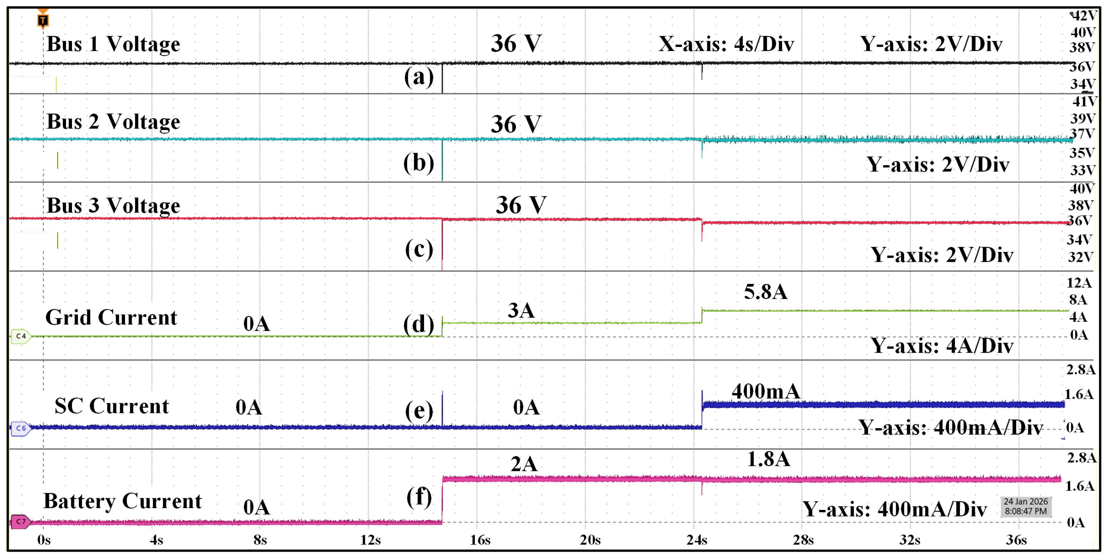
As the primary objective is to utilize the SC under the transient conditions and heavy loading conditions, voltage drop at the bus is considered as the parameter for the SC operation. If the bus voltage varies between , SC is operated. Figure 10 denotes the dynamic loading conditions, where the load on the DC MG is varied from to and finally to . It can be observed that, SC will not operate in light and moderate load conditions, when the load increases to , SC starts discharging. During loading of , DERs contribute and battery contributes . When the load increases from to , contribution from the DER’s increases to and battery contributes around , here SC starts contributing .
SC operation is also verified during the transient conditions, from the Figure 10, it can be observed that around when the load increases from to , there will be a slight voltage drop at the DC bus which initiates the supercapacitor operation for an instance. The zoomed version of that instance can be observed from Figure 11.
A practical scenario of partial shading is implemented where the capacity of one of the PV emulator is restricted. Here the CC limit of is placed on the emulator. Where the current contributions of each emulator is observed as , and respectively. During the loading of ; , and are the contributions DER’s, battery and SC respectively as shown in Figure 12. When the loading increases to , DER contribution increases to and SC contributes and battery remains at .
4. Conclusions
The proposed methodology design a hybrid data driven framework for HESS optimization. The proposed scheme is resilient and robust during renewable intermittency and the highly dynamic loading conditions. By explicitly calculating the dynamic characteristics of the battery and SC’s an effective power balancing with reduced stress on the storage elements is achieved.
An efficient decoupling of the fast and slow dynamics of storage elements allows effective handling of high frequency fluctuations by SC’s. Building on this, a hybrid EMS combining data-driven decision-making with PSO was introduced. In the proposed framework, SC operated by a trained data-driven model, enabling rapid transient response, whereas battery power allocation is optimized using PSO to ensure optimal energy usage and SoC regulation over longer time horizons. Proposed methodology is validated through both simulation and real time case studies under variable source and load conditions. The performance of the SC is examined under heavy loading and transient conditions. The results demonstrated improved transient response, enhanced DC bus voltage stability, and a noticeable reduction in battery stress compared to conventional HESS control strategies, confirming the robustness and practicality of the proposed approach.
Author Contributions
For research articles with several authors, a short paragraph specifying their individual contributions must be provided. The following statements should be used “Conceptualization, Sujatha.Banka and D.V Ashok Kumar.; methodology, Sujatha.Banka and D.V Ashok Kumar; software, Sujatha.Banka ; validation,Sujatha.Banka and D.V Ashok Kumar ; formal analysis, Sujatha.Banka and D.V Ashok Kumar; resources,Sujatha.Banka ; writing—original draft preparation, Sujatha.Banka; writing—review and editing, D.V Ashok Kumar ; visualization, D.V Ashok Kumar; supervision, D.V Ashok Kumar
Conflicts of Interest
The authors declare no conflicts of interest.
Abbreviations
The following abbreviations are used in this manuscript:
| DCMG | DC Microgrid |
| EMS | Energy Management System |
| PSO | Particle Swarm Optimization |
| NN | Neural Networks |
| SC | Super Capacitor |
| BESS | Battery Energy Storage System |
| HESS | Hybrid Energy Storage System |
| SoC | State of Charge |
| MPC | Model Predictive Control |
| DER | Distributed Energy Resources |
| PEC | Power Electronic Converters |
| CC | Constant Current |
References
- Khushoo, M.; Sharma, A.; Kaur, G. DC microgrid-A short review on control strategies. Materials Today: Proceedings 2022, 71, 362–369.
- Shabbir, G.; Hasan, A.; Yaqoob Javed, M.; Shahid, K.; Mussenbrock, T. Review of DC Microgrid Design, Optimization, and Control for the Resilient and Efficient Renewable Energy Integration. Energies 2025, 18, 6364.
- Dhar, R.K.; Merabet, A.; Al-Durra, A.; Ghias, A.M. Power balance modes and dynamic grid power flow in solar PV and battery storage experimental DC-link microgrid. Ieee Access 2020, 8, 219847–219858.
- Vivas, F.; Segura, F.; Andújar, J.; Calderón, A.; Isorna, F. Battery-based storage systems in high voltage-DC bus microgrids. A real-time charging algorithm to improve the microgrid performance. Journal of Energy Storage 2022, 48, 103935.
- Khan, K.A.; Khalid, M. Improving the transient response of hybrid energy storage system for voltage stability in DC microgrids using an autonomous control strategy. IEEE Access 2021, 9, 10460–10472.
- Aghmadi, A.; Ali, O.; Mohammed, O.A. Stability Enhancement of DC Microgrid Operation Involving Hybrid Energy Storage and Pulsed Loads. IEEE Transactions on Consumer Electronics 2025.
- Adhikari, S.; Lei, Z.; Peng, W.; Tang, Y. A battery/supercapacitor hybrid energy storage system for DC microgrids. In Proceedings of the 2016 IEEE 8th International Power Electronics and Motion Control Conference (IPEMC-ECCE Asia). IEEE, 2016, pp. 1747–1753.
- Grisales-Noreña, L.F.; Montoya, O.D.; Ramos-Paja, C.A. An energy management system for optimal operation of BSS in DC distributed generation environments based on a parallel PSO algorithm. Journal of Energy Storage 2020, 29, 101488.
- Wu, T.; Ye, F.; Su, Y.; Wang, Y.; Riffat, S. Coordinated control strategy of DC microgrid with hybrid energy storage system to smooth power output fluctuation. International Journal of Low-Carbon Technologies 2020, 15, 46–54.
- Ferahtia, S.; Djerioui, A.; Rezk, H.; Chouder, A.; Houari, A.; Machmoum, M. Adaptive droop based control strategy for DC microgrid including multiple batteries energy storage systems. Journal of Energy Storage 2022, 48, 103983.
- Zhang, W.; Chen, J.; Riaz, S.; Zheng, N.; Li, L. Research on Distributed Cooperative Control Strategy of Microgrid Hybrid Energy Storage Based on Adaptive Event Triggering. CMES-Computer Modeling in Engineering & Sciences 2022, 132.
- Gbadega, P.A.; Sun, Y. A hybrid constrained Particle Swarm Optimization-Model Predictive Control (CPSO-MPC) algorithm for storage energy management optimization problem in micro-grid. Energy Reports 2022, 8, 692–708.
- Vedulla, L.K.; Mishra, M.K. PSO based power sharing scheme for an islanded DC microgrid system. In Proceedings of the IECON 2017-43rd Annual Conference of the IEEE Industrial Electronics Society. IEEE, 2017, pp. 392–397.
- Tianqi, L.; Guochen, Y.; Jing, G.; Fang, L.; Xueyan, P. Research on control strategy of storage and DC hybrid energy storage based on new energy microgrid. In Proceedings of the 2022 IEEE 2nd International Conference on Data Science and Computer Application (ICDSCA). IEEE, 2022, pp. 328–333.
- Hu, Q.; Xie, S.; Zhang, J. Data-based power management control for battery supercapacitor hybrid energy storage system in solar DC-microgrid. Scientific Reports 2024, 14, 26164.
- Ali, N.; Shen, X.; Armghan, H. A hybrid approach involving data driven forecasting and super twisting control action for low-carbon microgrids. Applied Energy 2025, 398, 126429.
- Anu, A.; Arunkumar, C.; Hari Kumar, R.; Annie, B.; Shihabudheen, K.; Dileep, G.; et al. Adaptive particle swarm optimization based controller design for stability enhancement of standalone DC microgrid. Journal of Energy Storage 2024, 98, 113012.
- Lukic, S.M.; Cao, J.; Bansal, R.C.; Rodriguez, F.; Emadi, A. Energy storage systems for automotive applications. IEEE Transactions on industrial electronics 2008, 55, 2258–2267.
- Bahloul, M.; Khadem, S.K. Impact of power sharing method on battery life extension in HESS for grid ancillary services. IEEE Transactions on Energy Conversion 2018, 34, 1317–1327.
- Khaligh, A.; Li, Z. Battery, ultracapacitor, fuel cell, and hybrid energy storage systems for electric, hybrid electric, fuel cell, and plug-in hybrid electric vehicles: State of the art. IEEE transactions on Vehicular Technology 2010, 59, 2806–2814.
- Banka, S.; Kumar, D.V.A. Energy Optimization of HESS Integrated DCMG: PSO Based Approach. In Proceedings of the 2025 Third International Conference on Cyber Physical Systems, Power Electronics and Electric Vehicles (ICPEEV), 2025, pp. 1–6. [CrossRef]
Figure 2.
Power profile of PV generation and load demand.
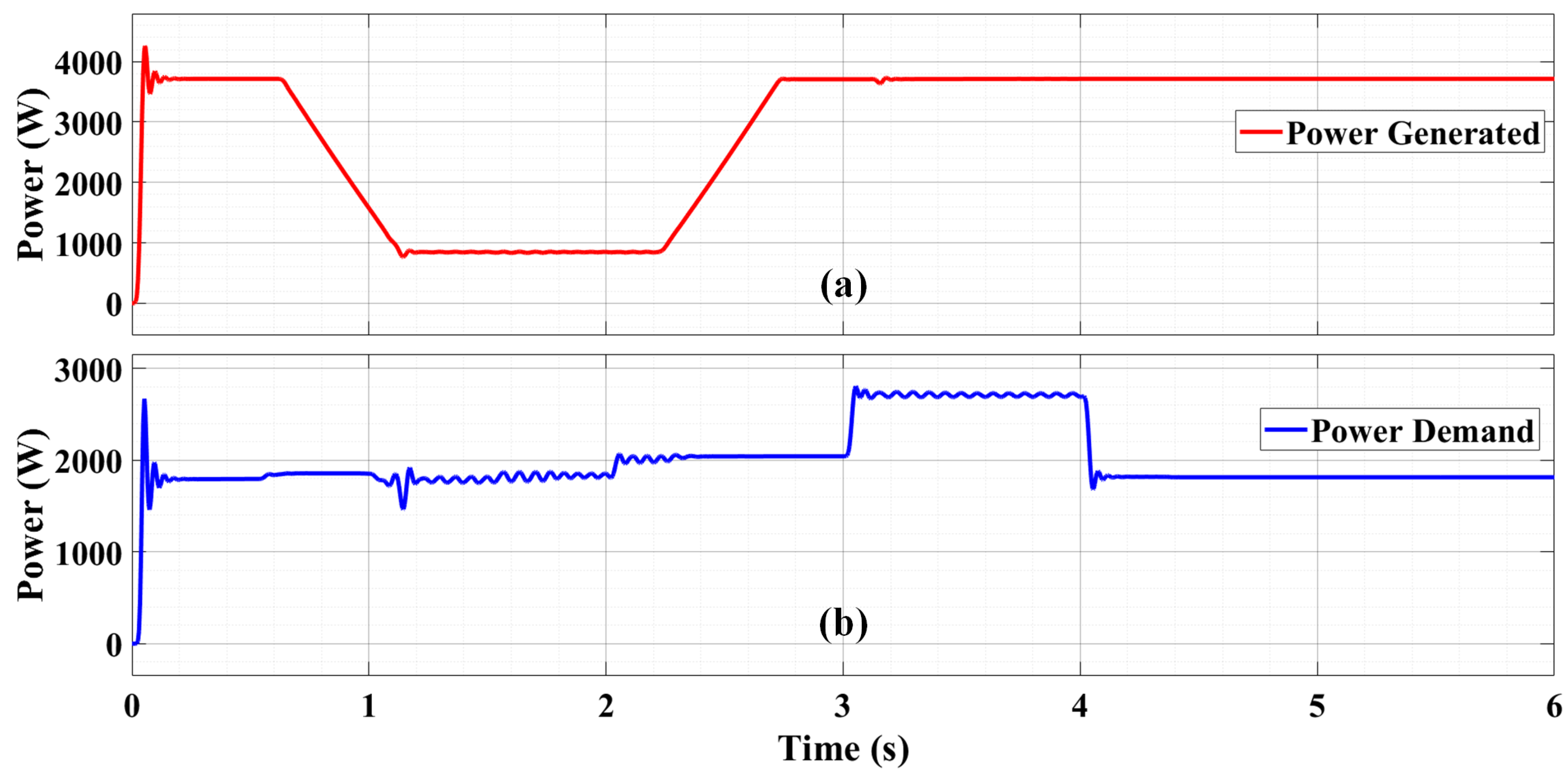
Figure 3.
Loading pattern at respective nodes of DC MG.
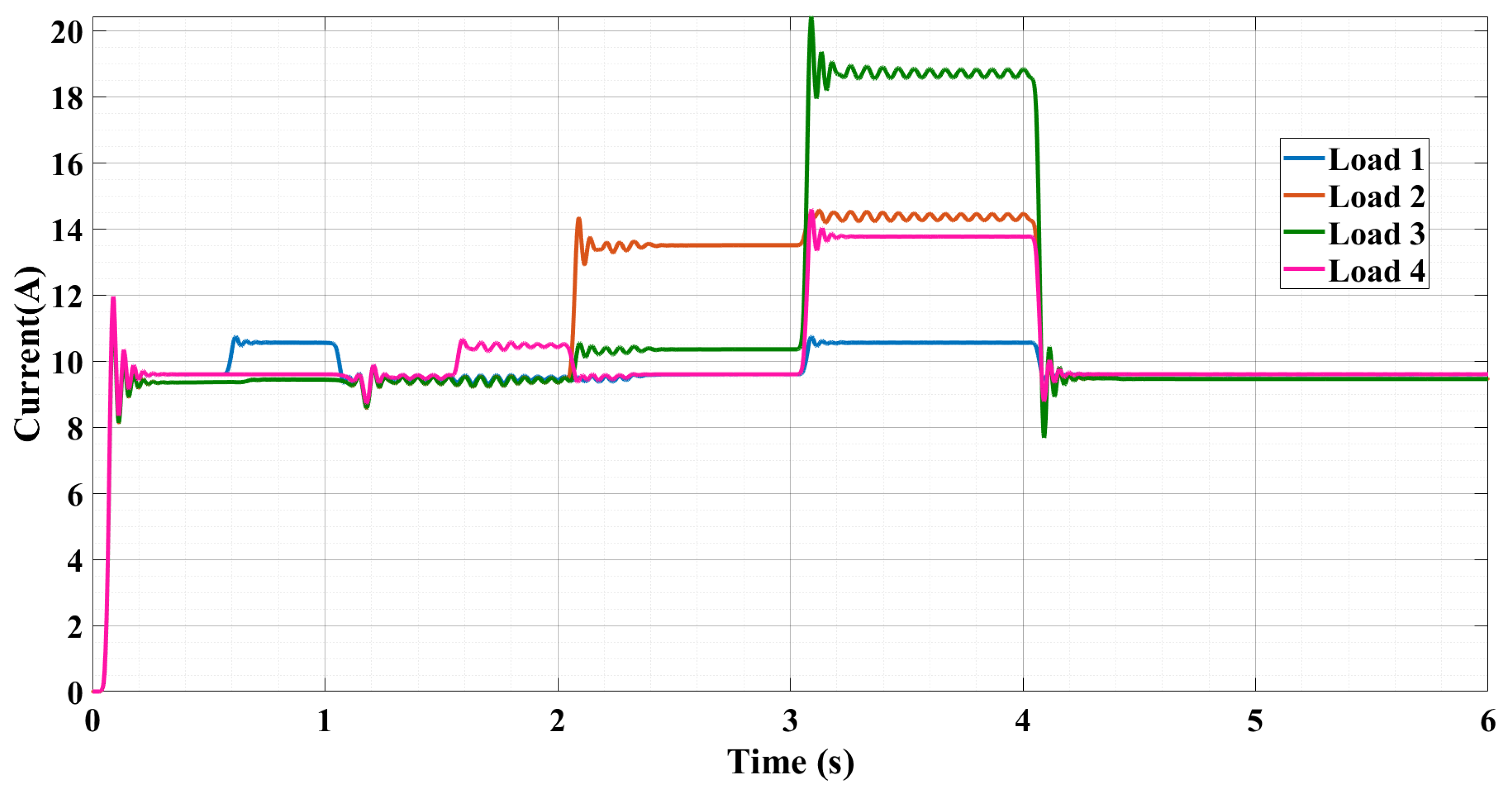
Figure 4.
SC compensation pattern during grid disturbances.
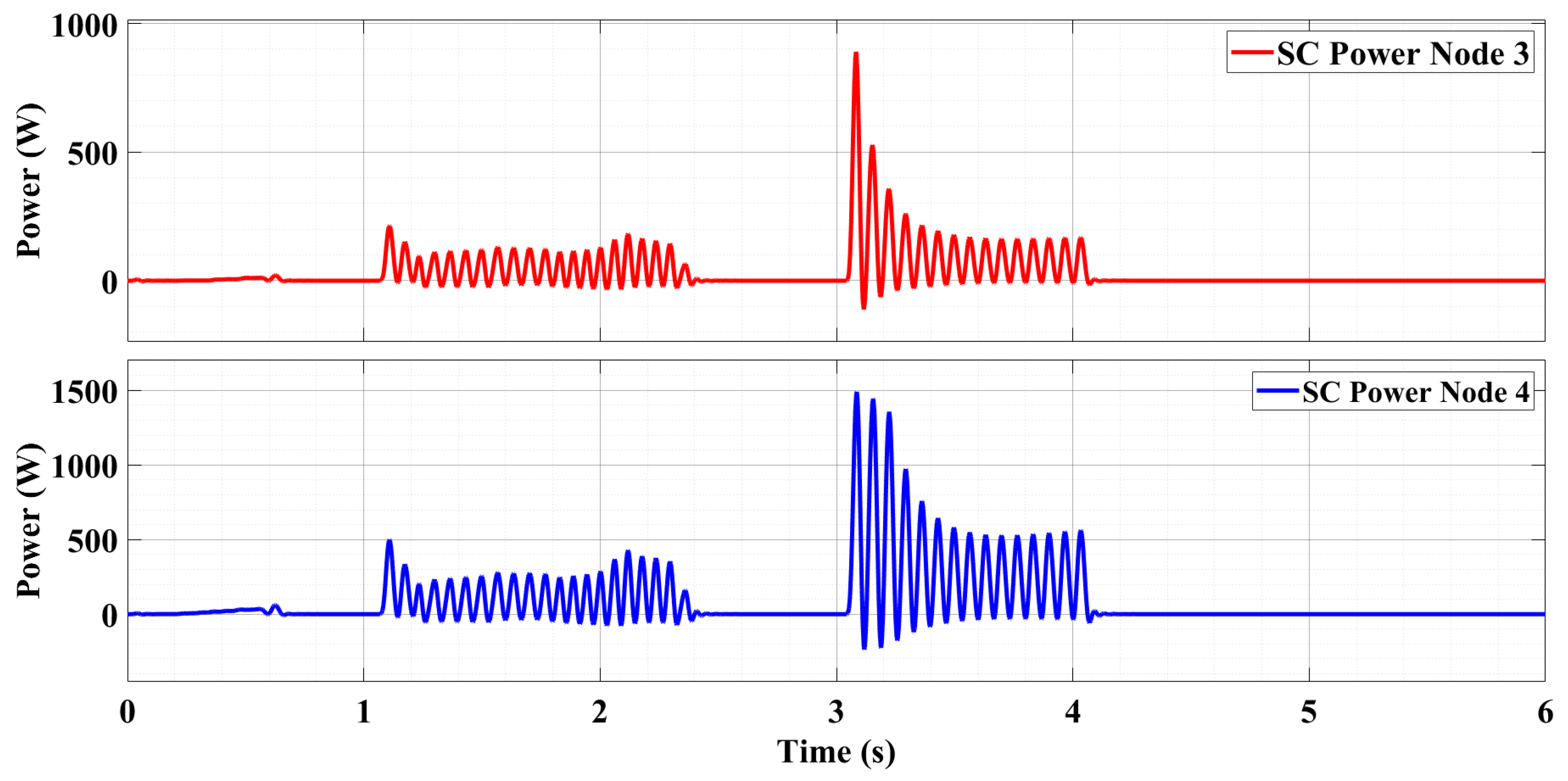
Figure 5.
Analysis of node power and load power at each bus.
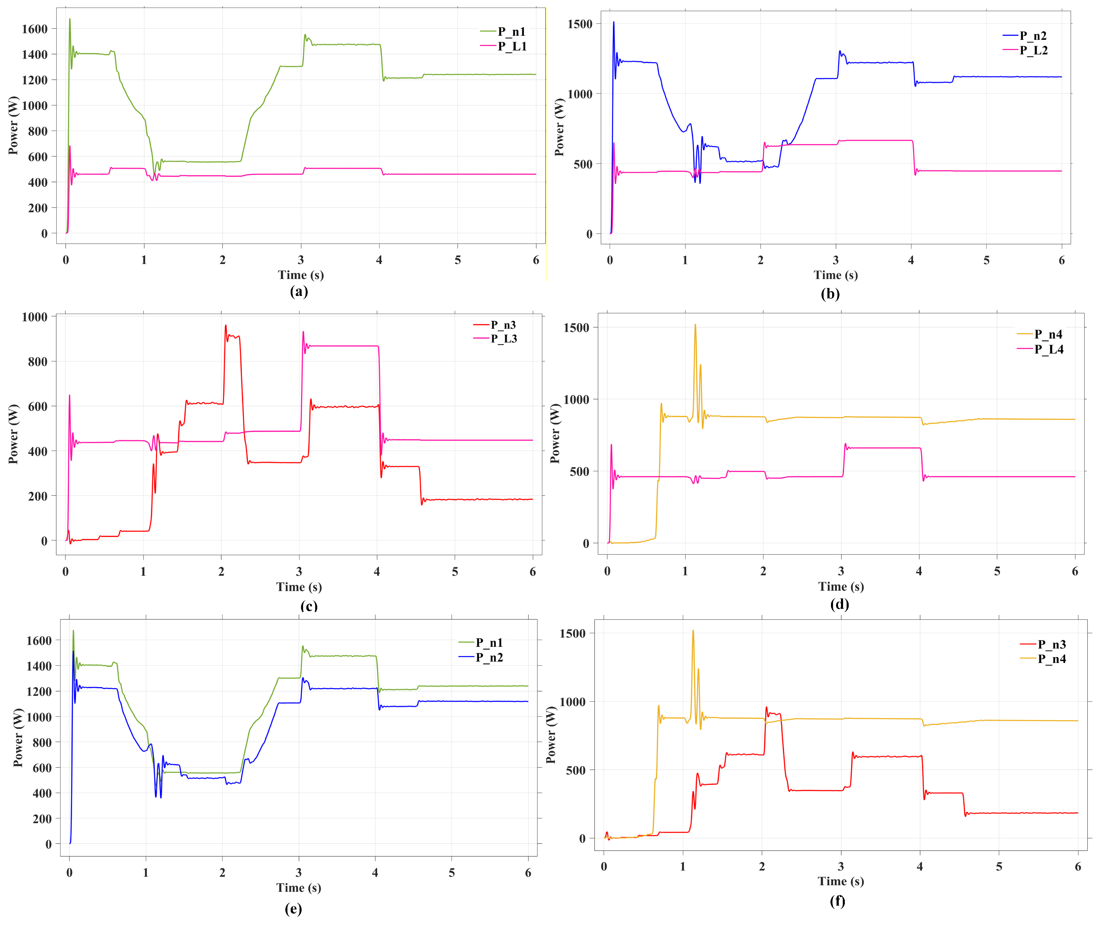
Figure 6.
Representation of Bus voltages and Bus currents.
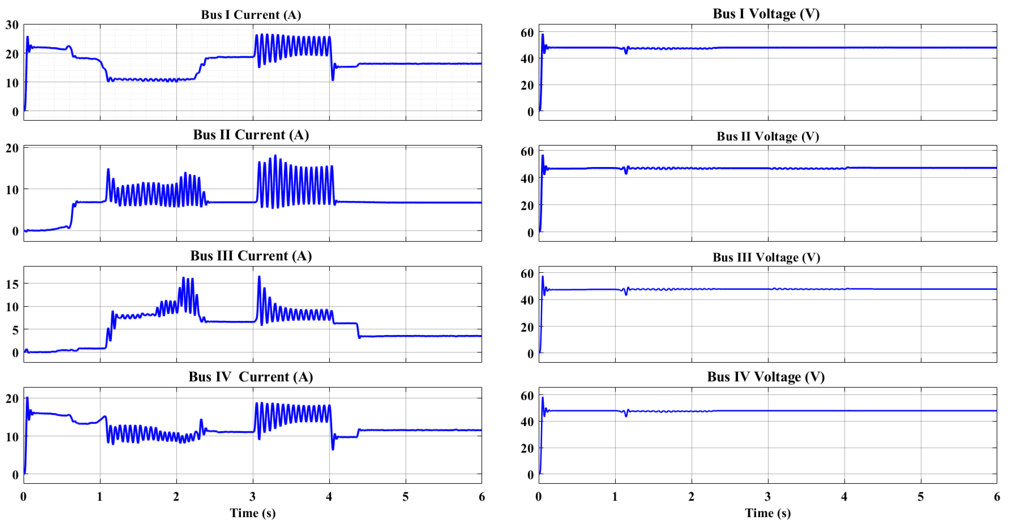
Figure 7.
Voltage profile of Bus voltages.
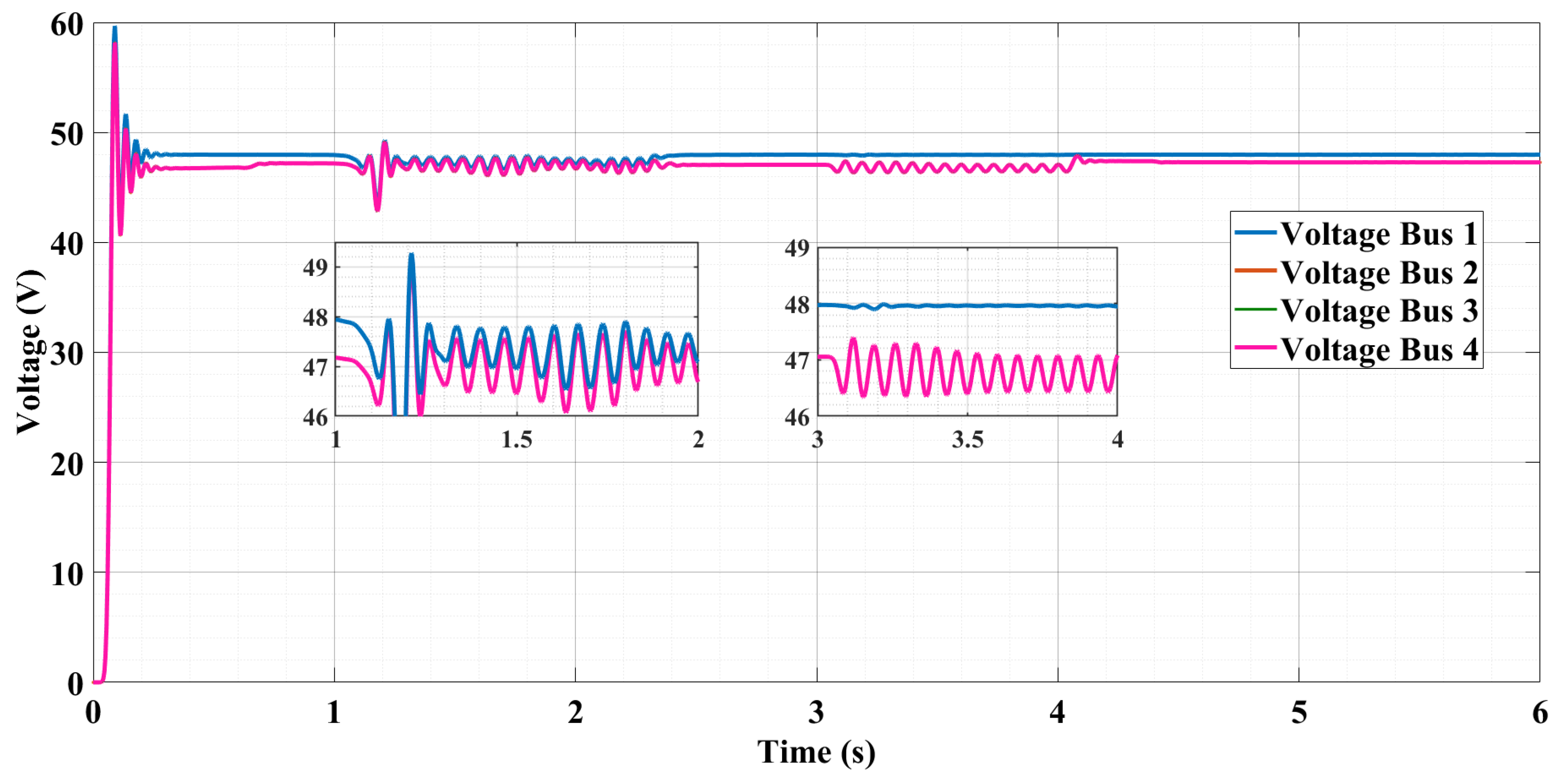
Figure 8.
Real-time experimental testbed of 3kW ringmain DC MG system.
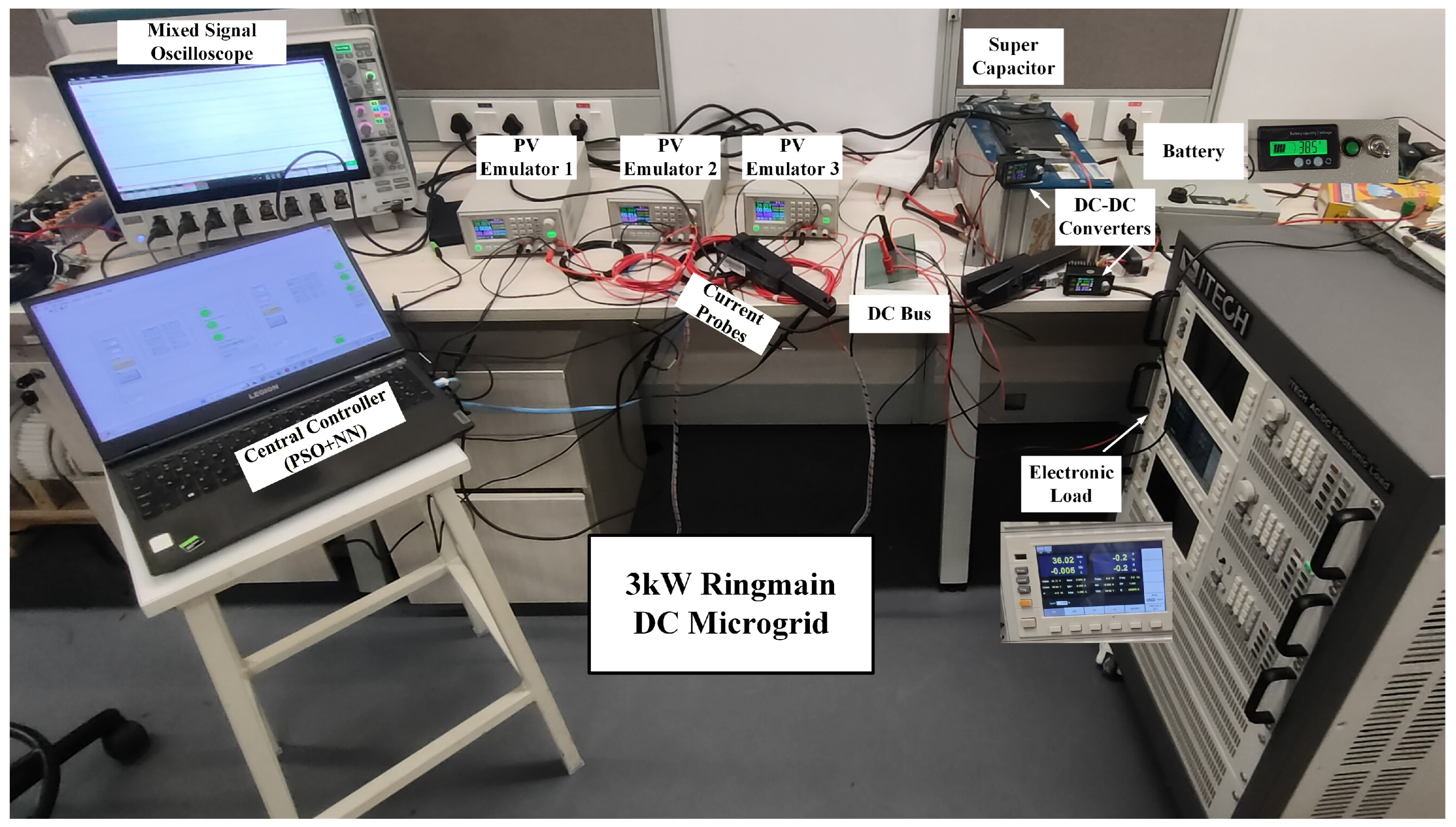
Figure 9.
Voltage regulation of DC MG.
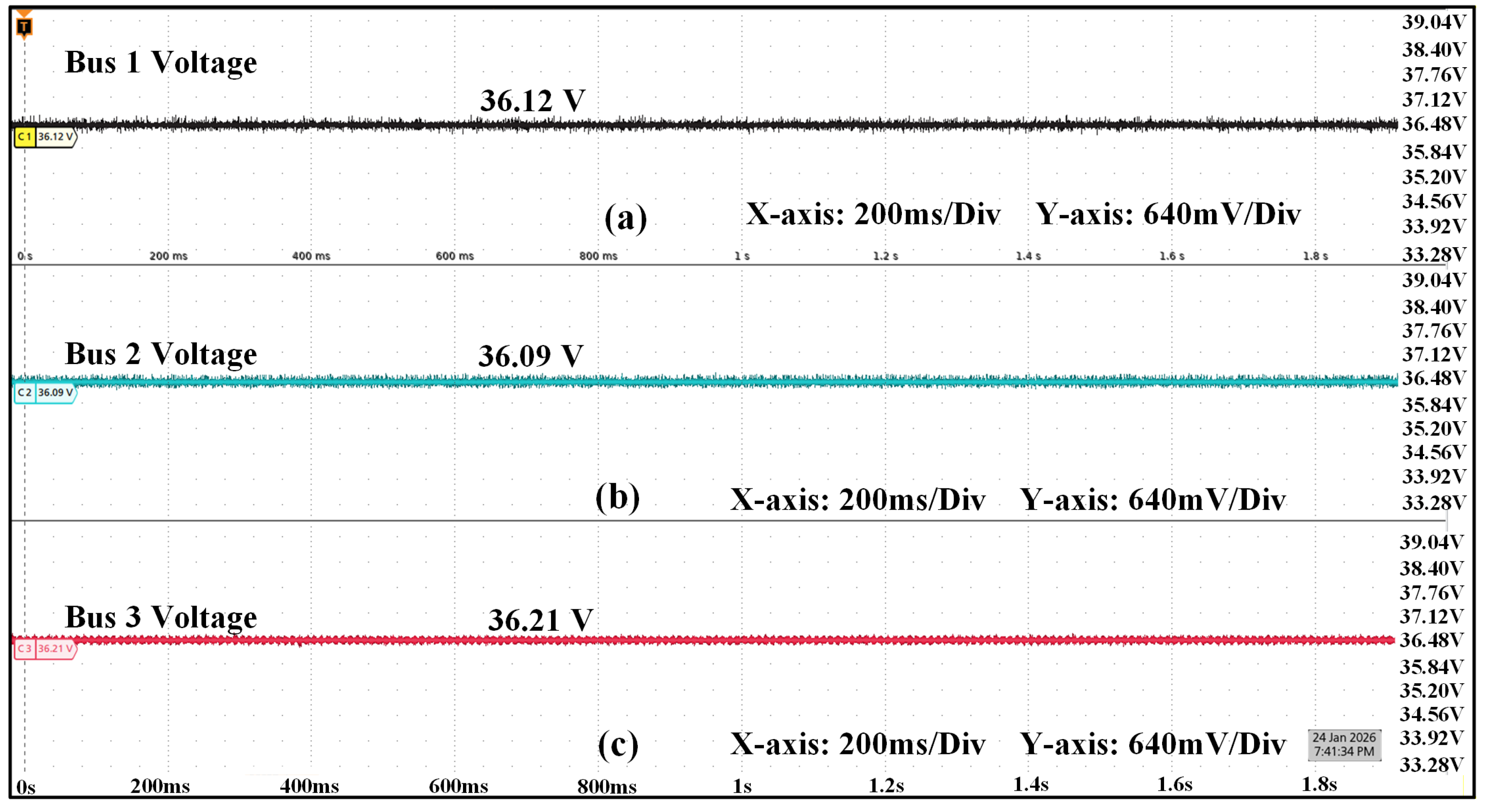
Figure 10.
Dynamic loading on DC MG.
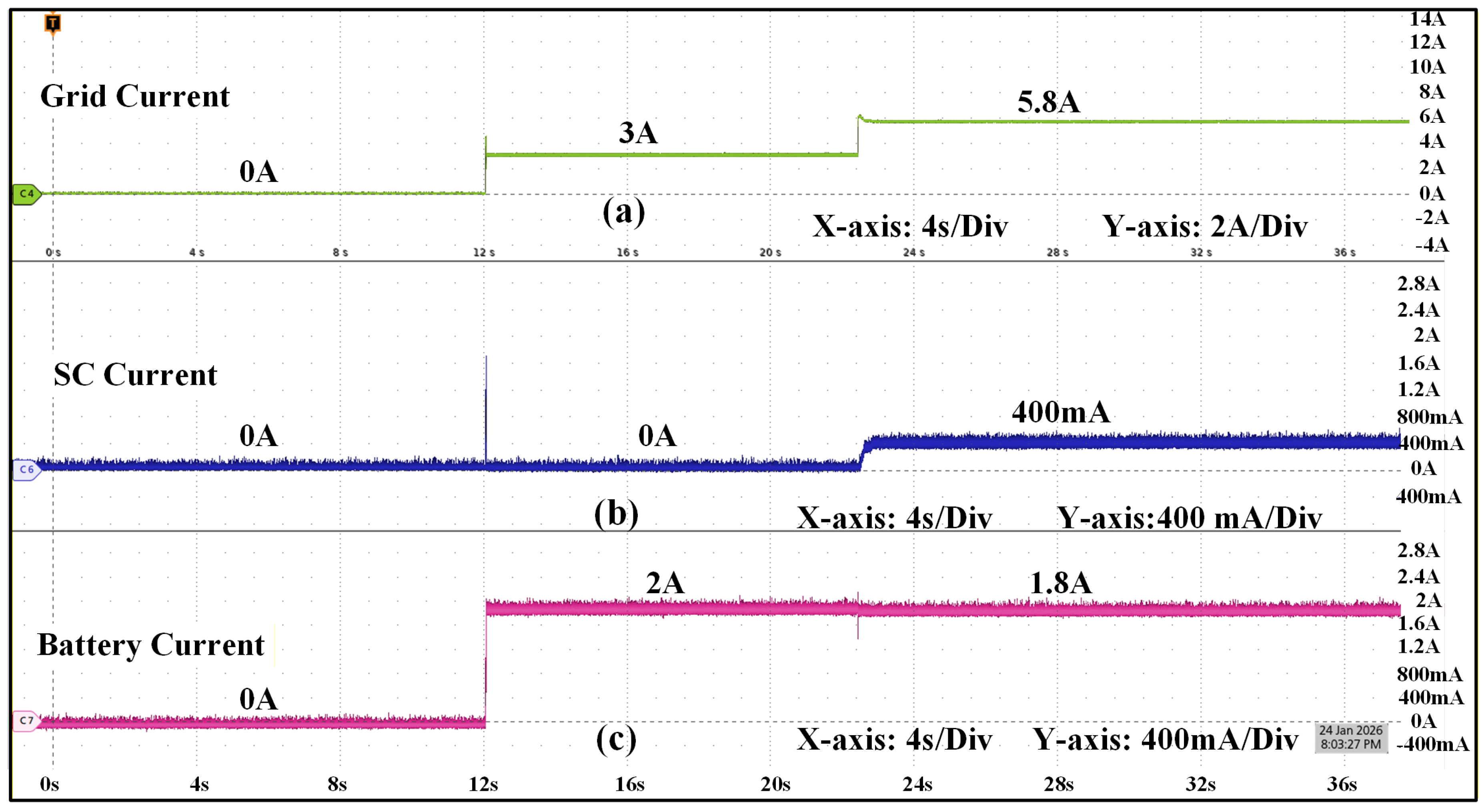
Figure 11.
SC operation during transient condition.
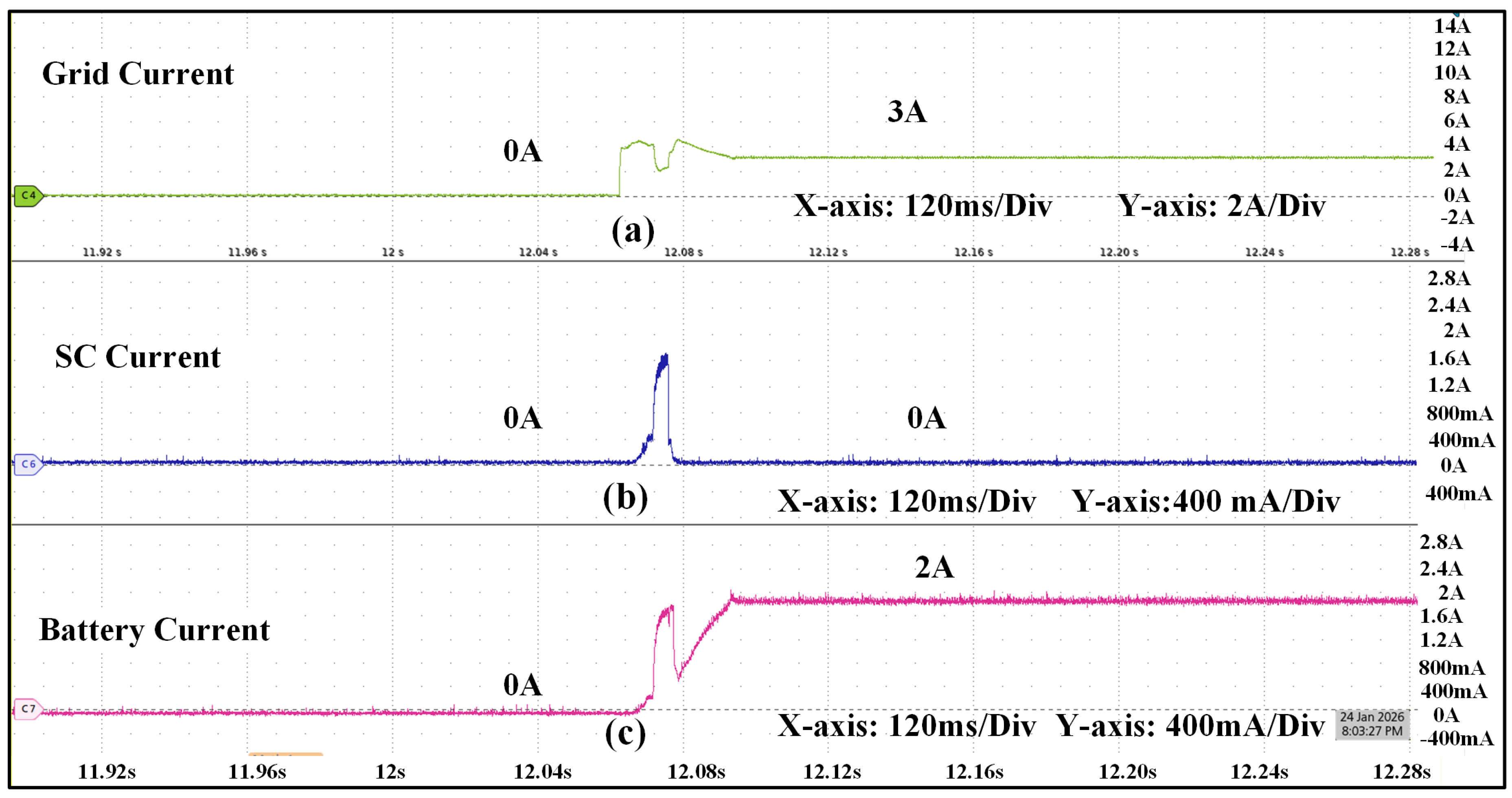
Figure 12.
Bus currents during intermittent PV generation.
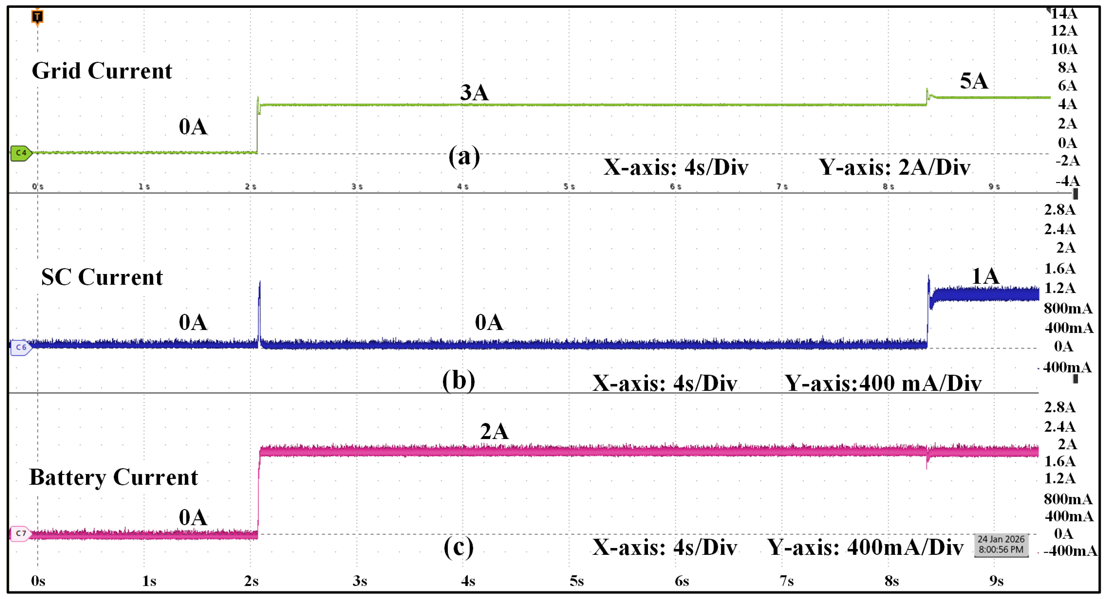
Figure 13.
Bus voltage and Bus currents during dynamic loading conditions.
Disclaimer/Publisher’s Note: The statements, opinions and data contained in all publications are solely those of the individual author(s) and contributor(s) and not of MDPI and/or the editor(s). MDPI and/or the editor(s) disclaim responsibility for any injury to people or property resulting from any ideas, methods, instructions or products referred to in the content. |
© 2026 by the authors. Licensee MDPI, Basel, Switzerland. This article is an open access article distributed under the terms and conditions of the Creative Commons Attribution (CC BY) license (http://creativecommons.org/licenses/by/4.0/).
Copyright: This open access article is published under a Creative Commons CC BY 4.0 license, which permit the free download, distribution, and reuse, provided that the author and preprint are cited in any reuse.


