Submitted:
02 February 2026
Posted:
03 February 2026
You are already at the latest version
Abstract
The development of high-performance anode materials is essential to overcome the limitations associated with conventional graphite electrodes in lithium-ion batteries, and perovskite oxides emerge as promising alternatives due to their structural flexibility and defect chemistry. In this work, the potential of LaSrCoFeO₃ perovskite (LSCF) thin films as anode materials is investigated, with particular emphasis on the effect of the post-deposition annealing atmosphere. LSCF thin films were deposited by dc magnetron sputtering and then thermal-treated at 600 °C in air and vacuum. The structural, electrical and electrochemical characterizations show that vacuum annealing promotes a more efficient crystallization, leading to larger crystallites (~ 240 nm), and to reduced oxidation due to the formation of oxygen vacancies. This reduced state significantly reduces electrical conductivity to ~10-6 Ω·cm. When evaluated as a half-cell anode, the vacuum-annealed films exhibit a theoretical specific capacity of 121 mAh·g-1, high reversibility with anodic and cathodic charge ratio Qa/Qc ≈ 1 and a good cyclic stability, with a loss of discharge capacity of less than 10%. Raman spectroscopy confirmed that the film structure remains unchanged upon the electrochemical tests, evidencing their stability. These results show that the annealing atmosphere is a determining parameter to optimize the electrochemical performance of LSCF thin films, reinforcing their potential as anodes for future lithium-ion batteries.
Keywords:
LaSrCoFeO3
; thin films
; magnetron sputtering
; transparent electrodes
; lithium-ion batteries
; annealing
1. Introduction
Lithium-ion batteries (LIBs) have received wide attention as energy storage systems in portable devices and electric vehicles, due to their high energy density, long lifespan, and reliability [1,2,3]. However, the relatively low specific capacity of conventional anode materials, such as graphite (372 mAh·g-1), limits LIBs energy performance [4].
In recent decades, alternative anode materials that offer higher capacity, mechanical stability and safety have been investigated. Among them, transition metal oxides (MO, where M = Co, Ni, Cu, Fe) stand out for their high reversible electrochemical capacity and good storage mechanisms based on conversion reactions [5,6].
The study of cobalt-based perovskites as electrode materials has been strongly based on their known mixed ion-electronic conduction capacity. In seminal work, Chen et al. [7] evaluates the ionic conductivity of LaCoO3 using an oxygen permeation technique, demonstrating that this material exhibits significant oxygen ion mobility in its lattice, attributed to its defect-tolerant perovskite structure. Following this, Zhang et al. [8] investigates the electrochemical reactions between LaCoO3 and lithium, revealing that this oxide can participate in reversible Li+ insertion/extraction processes, maintaining its structural integrity. These studies, conducted on bulky samples (not thin films), set a crucial precedent: if a perovskite is able to efficiently transport oxygen ions (relatively large anions), its open structure and defect chemistry may also facilitate the diffusion of lithium ions, which are smaller and have a lower charge. This functional analogy between O2- and Li+ transport suggests that perovskites such as LaCoO3, and especially its Sr-doped variants, which introduce oxygen vacancies and modulate electronic conductivity, have intrinsic potential as mixed-conductive anode materials (Li+/e-). However, the transition of this potential to practical and competitive electrochemical performance requires material optimization and design at the microstructural and interface level that is particularly accessible through thin-film technology. This approach allows a precise control of the thickness, texture and density of defects, determining factors for lithium insertion kinetics and for life cycle stability, as the present work explores in the LaSrCoFeO3 system.
The demand for higher capacity anode materials has led to the exploration of more complex oxides, such as cobalt perovskites. However, its development faces key challenges, including modulating its work potential. A seminal study by Li et al. [9] demonstrates that the addition of rare earth elements (RE), such as La, to transition metal oxides (TM) can effectively lower the operating potential, an advantageous feature for increasing cell voltage. However, this strategy reveals a critical trade-off: RE oxides act as electrochemically inactive phases, diluting the total specific capacity of the material (~300 – 400 mAh·g-1), which limits its commercial relevance [9]. This compromise between potential and specific capacity defines a central axis for the optimization of perovskite anodes.
In addition to cationic doping, anion sublattice engineering has emerged as a powerful avenue to reconfigure the properties of perovskites. Recently, Wei et al. [10] reported that the incorporation of hydrogen as a hydride anion (H-) in LaCoO3 thin films, via topotactic reduction, transforms the material into the H-LaCoO2.5 phase. This modification induces a contraction of the lattice, alters cobalt’s valence state and, crucially, stabilizes an insulating ferromagnetic state above ambient temperature. This work not only illustrates the profound impact of inserting light anions into the electronic structure but also suggests that anionic manipulation can be a lever to simultaneously control ion transport and electronic properties in electrode materials.
At the same time, nanoengineering of interfaces and defects is also important. Zhang et al. [11] demonstrates that the configuration of oxygen vacancies in LaCoO3-x thin films is extraordinarily sensitive to boundary conditions. By creating heterostructures with BiFeO3 (BFO) or PbTiO3 (PTO), it is possible to atomically control the concentration, period (2 or 3 unit cells) and orientation (vertical vs. horizontal) of the vacancy order. This level of control, achieved through the coupling between grid voltage, broken symmetry at the interface and ferroelectric polarization, is key to optimizing lithium-ion diffusion, which depends closely on the configuration of these defects. Geary et al. [12] report on the linear and nonlinear electrochemical impedance spectroscopy to study 20 nm thick epitaxial La0.6Sr0.4Co0.2Fe0.8O3-δ thin films at 600 °C in oxygen atmosphere, in particular of Sr segregation in these conditions.
In this context, the present work proposes an integrated approach, focusing on LaSrCoFeO3 thin films deposited by non-reactive dc magnetron sputtering. The LSCF system combines cationic doping with Sr to create oxygen vacancies and modulate the electronic structure with the complexity of a perovskite containing two transition metals (Co and Fe). Inspired by the principles outlined in previous studies [9,10,11], this study systematically investigates how microstructure, film thickness, composition and post-deposition annealing influences defect ordering, mixed conduction (Li+ ions and electrons), and final electrochemical performance. The goal is to overcome the capacity-potential relationship, paving the way for the development of efficient and stable perovskite anodes for the next generation of LIBs.
2. Materials and Methods
LaSrCoFeO3 thin films were deposited on glass lamella and aluminum foil substrates using a magnetron sputtering system in direct current (dc) and non-reactive mode. A La0.6Sr0.2Co0.4Fe0.8O3 sputtering target (Testbourne B.V., purity 99.9%) was used as the source of the thin film. Before deposition, the substrates were thoroughly cleaned in an ultrasound bath with isopropyl alcohol for 15 minutes. The deposition chamber was first evacuated to a baseline pressure of approximately 2.8x10⁻⁴ Pa. Subsequently, and prior to film deposition, an argon (Ar) atmosphere was introduced and a plasma etching process was carried out on the substrates for 3 minutes at a bias voltage of -550 V to remove any surface contaminants and induce atomistic defects that enable optimized film growth. The substrate carrier was kept in rotation at 20 rpm to ensure homogeneity during this Ar+ ion etching process. The LSCF thin films were grown under the following optimized conditions: a working pressure of 0.8 Pa; target current density of 4 mA·cm-2; bipolar substrate bias of -60 V at a frequency of 100 kHz with a 70% duty-cycle. The deposition time was set to 60 minutes, resulting in films with an average thickness of (150 ± 40 nm), as determined by optical spectrophotometry and subsequent simulation of the transmittance and reflectance curves using the Scout software (Theiss).
2.1. Post-Deposition Heat Treatment
The as-deposited thin films were subjected to a thermal treatment (TT) at 600 °C for 2 hours in two different atmospheres (air and vacuum) to induce crystallization and study its effect on the structural properties:
- TT in air: carried out in a conventional furnace (Nabertherm) at atmospheric pressure.
- TT in vacuum: carried out in a vacuum furnace under a residual pressure of approximately 10-3 Pa.
In both cases, a controlled heating and cooling rate of 5 °C·min-1 was used to minimize heat stress.
2.2. Structural, Local and Morphological Characterization
The crystal structure of the LSCF films was analyzed by X-ray diffraction (XRD) using a Bruker AXS D8 Advance diffractometer with Cu Kα radiation (λ = 1.54184 Å) at SEMAT/UM (University of Minho). The measurements were performed in grazing incidence mode (ω = 1°) with a 2θ scan between 10° and 80°, 2 s integration time and step interval of 0.02°. A Rietveld refinement was performed to the diffraction data using the Bruker TOPAS software to determine the lattice parameters and crystallite size.
Raman spectroscopy was performed with a ALPHA300 R Confocal Raman Microscope (WITec) at room temperature, using 532 nm Nd:YAG laser as the excitation source, to evaluate the local structure and vibrational modes.
The surface morphology and chemical composition of the films were investigated by scanning electron microscopy (SEM) using a FEI NOVA 200 FEG-SEM equipment at SEMAT/UM (University of Minho), equipped with an X-ray energy dispersive spectroscopy (EDS) system, with a voltage of 15 kV.
2.3. Electrical Characterization
Electrical resistivity (ρ), charge carrier concentration (n) and charge mobility (μ) were determined at room temperature using a Hall Effect measurement system (Ecopia HMS - 5000) with a magnetic field of 0.56 T.
2.4. Electrochemical Characterization
The electrochemical performance of LSCF thin films was evaluated as anodes in lithium-ion half-cells. The films deposited on aluminum foil were cut into discs of 8 mm diameter (geometric area: 0.5024 cm²) and dried at 25 °C for 24 hours in a Buchi TO 51 furnace before assembling the anode half-cell (Figure 1). The cells were mounted in a glovebox with an argon atmosphere, using a Swagelok-type configuration. LSCF film was used as the working electrode, a lithium metal foil functioned simultaneously as a counter-electrode and reference electrode, and a fiberglass filter (Whatman GF/D) was used as a separator. 1 mol/L of LiPF6 in a 1:1 (v/v) mixture of ethylene carbonate (EC) and dimethyl carbonate (DMC) was used as the electrolyte.
Cyclic voltammetry (CV) tests were performed between 2.5 and 4.2 V (vs. Li+/Li) at various scan speeds (0.1 to 0.4 mV/s) using a potentiostat. Galvanostatic charge-discharge cycling was performed at different current rates (from C/8 to 1C) to evaluate the specific capacity and cyclic stability. Electrochemical impedance spectroscopy (EIS) measurements were performed before and after cycling to evaluate the formation of anode-electrolyte interfaces.
3. Results
3.1. Structural, Local and Morphological Characterization
Structural analysis by XRD confirms that the as-deposited thin films have an amorphous structure. Post-deposition thermal treatments (TT) at 600 °C induces the crystallization into the orthorhombic perovskite phase (space group Pbnm, 62), as illustrated in Figure 2 a-b. The TT atmosphere proved to be a critical factor, since the vacuum treatment promotes significantly larger crystalline growth, resulting in an average crystallite size (g) of ~240 nm, in contrast to the ~80 nm observed in the air-treated film (Table 1). This marked difference suggests that reducing atmosphere (vacuum) favors greater atomic mobility during annealing.
Raman spectroscopy was used to evaluate the local structure and oxidation state of the films. The Raman spectra (Figure 3) exhibit in the ~650 cm⁻¹ region the characteristic O ̶ (Co/Fe) stretching modes. Marked differences are observed between the samples, mainly revealing that this peak is a contribution from two Raman modes: one at ~ 650 cm-1 and a shoulder at ~ 560 cm-1), whose intensity varies with the TT treatment. The vacuum-treated thin film exhibits an (I650/I560) intensity ratio of 4.6, while the air-treated thin film exhibits a significantly smaller I650/I560 ratio of 2.5.
According to the literature [13], the ~560 cm-1 mode is associated with a higher oxidation state of the material. Thus, Raman data validate that TT in air produces a more oxidized material, while TT in vacuum results in a consistently shorter phase, corroborating the formation of oxygen vacancies (Vo••) in the latter. This conclusion is key to explaining the differences in electrical and electrochemical properties.
SEM analysis (Figure 4 a-b-c) reveal that the vacuum-treated film (Figure 4c) exhibits a denser and more homogeneous surface, while the air-treated film (Figure 4b) exhibits a rougher morphology with segregated particles. The as-deposited film has the rougher surface with micrometer size defects.
EDS was used to determine the film composition (Table 2). The LSCF films have 50 to 60 at.% of oxygen, which is that of the sputtering target used, and bearing in mind that film depositions were performed in non-reactive mode. The as-deposited LaSrCoFeO₃ film exhibits a higher oxygen content compared to the annealed states. Sr is present at ~5 at.%, slightly lower than its concentration in the sputtering target (~8 at.%). The Co content increases from 1.58 at.% in the as-deposited film to 3.16 at.% after vacuum annealing, approaching the target value of ~4 at.%. An enrichment in La is observed from the as-deposited state (~8 at.%) to the air-annealed (~10.5 at.%) and vacuum-annealed (~11.5 at.%) states, the latter being close to the target composition (~12 at.%). These changes indicate that post-deposition thermal treatments at 600 °C promote cation diffusion and redistribution within the film, leading to a more homogeneous composition and values closer to those of the sputtering target.
The as-deposited LaSrCoFeO₃ film exhibits a higher oxygen content compared to the annealed films at 600 °C. Sr is present in the range of ~5 at.%, which is slightly inferior to the content of this element (~8 at.%) in the sputtering target. Cobalt almost doubles its content from 1.58 at.% (as-deposited) to 3.16 at% (vacuum annealed state), almost reaching ~4 at.% content in the sputtering target. An enrichment in La is registered from the as-deposited state (~8 at.%) to the air annealed (~10.5 at.%) and vacuum annealed (~11.5 at.%) states. The latter composition is close to that of La in the sputtering target (~12 at.%). Annealing at 600 °C enables bulk diffusion, redistributing cations and making the composition closer to the target. In conclusion, the reduction in oxygen content and surface enrichment in La (+40%) and Co (+97%) in the vacuum-treated film, compared to the as-deposited sample, is indicative of a loss of lattice oxygen and the formation of oxygen vacancies (Vo••), a phenomenon expected in a reducing environment.
3.2. Electrical Properties
Hall Effect measurements confirm that the LSCF films behave as p-type semiconductor. The vacuum-treated thin film exhibits a significantly larger concentration of charge carriers (2.3 ± 0.4) x 1022 cm-3 compared to the air-treated film (3.5 ± 0.1) x 1021 cm-3. This high concentration of carriers results in an extremely low electrical resistivity, of the order of 10-6 Ω cm. This near-metallic conductivity is a key attribute for electrode material, as it ensures efficient electron transport, minimizing ohmic losses and improving battery performance, especially at high discharge rates.
3.3. Electrochemical Properties of LSCF Films
The performance of LSCF thin films as anodes was evaluated in an anodic half-cell configuration in a lithium-ion battery. The cyclic voltammograms (Figure 5a) of the air-treated film shows low intense peaks and a pronounced hysteresis, reflecting slower kinetics and lower reversibility. Conversely, the vacuum-treated film (Figure 5b) exhibits well-defined pairs of reduction and oxidation peaks, indicative of a reversible process of insertion and disinsertion of lithium ions in the perovskite structure.
The reversibility of the process is quantified through the ratio between anodic and cathodic (Qa/Qc) charges. The vacuum-treated film shows larger Qa/Qc values consistently close to the unit (0.94 – 1.09) at all scanning speeds, demonstrating excellent coulombic efficiency. In contrast, the air-treated film exhibits smaller values (0.67 – 0.84), suggesting irreversible capacity losses.
Figure 6 presents the behavior of the peak current (Ipc) on the sweep velocity for the two TT samples.
The analysis of the dependence of the peak current (Ipc) on the sweep velocity reveals that the process in the vacuum-treated film is predominantly diffusion-controlled, with a linear correlation (R2 = 0.9833) between the cathodic peak current and the square root of the sweep velocity (Figure 6b), versus the (R2 = 0.9634) for the air-treated film (Figure 6a). This indicates that the insertion of lithium ion occurs in the volume of the material and is not limited to the surface, a highly advantageous characteristic for an anode material.
3.4. Evaluation of Performance as Anode in Lithium-Ion Battery
To concretely evaluate the potential application of the LSCF films as an anode, an anodal half-cell was manufactured (Figure 1). For this, the vacuum-treated LSCF film at 600 °C, which demonstrated the most promising structural and electrochemical properties, was integrated and tested as an anode in the anodic half-cell in a lithium-ion battery, achieving a theoretical specific capacity of 121 mAh.g-1, considering that the mass of the thin film with the current collector is 2.2 mg. To further evaluate the feasibility of using this LSCF film as an anode, the anodic half-cell was characterized, applying different currents and subjected to several cycles (C/8 to 2C-rate). Figure 7a) shows the charge and discharge profile for the LSCF thin film tested at the rate of C/8 (which corresponds to 26.6 μA), where it is possible to observe the oxidation-reduction processes. This profile is representative because for the other rates the behavior is similar, albeit with different values, as observed in Figure 7b). Considering the discharge values presented in Figure 7 a), a test was carried out to evaluate its discharge stability throughout the cycles, as registered in Figure 7b). Except for the low rates C, the discharge value is stable throughout the different cycles, demonstrating a good reversibility of the system.
Analyzing Figure 8 a), the discharge capacity value is stable over the various cycles with a battery capacity fading of less than 10%, which demonstrates that the thin film under study can be used as an anode in the next generation of microbatteries. Finally, to evaluate the interface that is established between the anode and the electrolyte, impedance spectroscopy was used to determine the resistance before and after the cycling of the batteries, as shown in Figure 8 b). It is verified that the total resistance after cycling increases due to the anode/electrolyte interface, reaching a maximum value of ~5000 Ω.
After testing the vacuum thermal treated LSCF film at 600 °C as an anode in a lithium-ion half-cell (Figure 7 and Figure 8), the sample's Raman spectrum was measured using the same experimental conditions as the Raman study performed before the electrochemical tests, to verify the sample's stability. Figure 9 shows the sample's Raman spectra before and after these tests. It is observed that the Raman spectrum of the sample after being subjected to the electrochemical tests is very similar to the Raman spectrum before the tests, indicating good stability and robustness of the film. Interestingly, the signal-to-noise ratio is higher after the tests, even though the position and width at half-height of the modes remain at the same values, as does the intensity ratio between the mode at 645 cm⁻¹ and the mode at 580 cm⁻¹.
4. Conclusions
In this work, LaSrCoFeO3 thin films were deposited by magnetron sputtering. The structural, electrical and electrochemical results constitute these films as highly promising anode materials for lithium-ion batteries. This investigation reveals that the post-deposition thermal treatment, particularly the atmosphere in which it is performed, is a critical parameter that determines the final electrochemical performance.
It is unequivocally concluded that heat treatment in vacuum at 600 °C gives the LSCF thin film a superior set of properties, when compared to an identical treatment at atmospheric pressure. This optimization manifests itself at several levels:
Structurally, it promotes significantly higher crystallinity, with a crystallite size approximately three times larger (~ 240 nm), and induces a lower oxidation state, with the formation of oxygen vacancies.
Electrically, this reduced state translates into a drastic increase in the concentration of major charge carriers (holes), giving the material an almost metallic conductor behavior with an extremely low resistivity (~10-6 Ω.cm).
Electrochemically, these characteristics culminate in exceptional performance as an anode with a stable discharge capacity, near-optimal reversibility (Qa/Qc charge ratio ≈ 1) and, most notably, robust cyclic stability, with a loss smaller than 10% in discharge capacity after more than 100 cycles.
Stability, the Raman spectrum of the sample after being subjected to the electro-chemical tests is very similar to the Raman spectrum before the tests, indicating good sta-bility and robustness of the film.
In summary, this study not only validates sputtering as a viable technique to produce LSCF anodes, but also establishes the control of the annealing atmosphere as a powerful tool to optimize its electrochemical properties. By bringing together quasi-metallic electrical conductivity, high intrinsic activity and remarkable robustness, the thin film of vacuum-treated LSCF is positioned as a high-potential candidate for the next generation of anodes in lithium-ion batteries, offering an alternative route to conventional materials.
Acknowledgements
This work was supported by the Portuguese Foundation for Science and Technology (FCT) in the framework of the Strategic Funding UID/04650/2025, https://doi.org/10.54499/UID/04650/2025. The authors also thanks the FCT for financial support under FCT Grant 2021.07361.BD (RSP). We also thank the researcher doctor Renato Gonçalves from the Chemistry Centre for all the support at electrochemical measurements.
References
- Armand, M.; Tarascon, J.-M. Building Better Batteries. Nature 2008, 451, 652–657. [Google Scholar] [CrossRef] [PubMed]
- Belharouak, I.; Amine, K. Li₂MTi₆O₁₄ (M = Sr, Ba): New Anodes for Lithium-Ion Batteries. Electrochem. Commun. 2003, 5, 435–438. [Google Scholar] [CrossRef]
- Tarascon, J.M.; Armand, M. Issues and Challenges Facing Rechargeable Lithium Batteries. Nature 2001, 414, 359–367. [Google Scholar] [CrossRef] [PubMed]
- Grosu, C.; Panosetti, C.; Merz, S.; Jakes, P.; Seidlmayer, S.; Matera, S.; Eichel, R.A.; Granwehr, J.; Scheurer, C. Revisiting the Storage Capacity Limit of Graphite Battery Anodes: Spontaneous Lithium Overintercalation at Ambient Pressure. PRX Energy 2023, 2, 013003. [Google Scholar] [CrossRef]
- Tarascon, J.-M.; Grugeon, S.; Morcrette, M.; Laruelle, S.; Rozier, P.; Poizot, P. New Concepts for the Search of Better Electrode Materials for Rechargeable Lithium Batteries. Comptes Rendus Chimie 2005, 8, 9–15. [Google Scholar] [CrossRef]
- Poizot, P.; Laruelle, S.; Grugeon, S.; Dupont, L.; Tarascon, J.-M. Nano-Sized Transition-Metal Oxides as Negative-Electrode Materials for Lithium-Ion Batteries. Nature 2000, 407, 496–499. [Google Scholar] [CrossRef] [PubMed]
- Chen, C.H.; Kruidhof, H.; Bouwmeester, H.J.M.; Burggraaf, A.J. Ionic Conductivity of Perovskite LaCoO₃ Measured by Oxygen Permeation Technique. Journal of Applied Electrochemistry 1997, 27, 71–75. [Google Scholar] [CrossRef]
- Zhang, D.W.; Xie, S.; Chen, C.H. Electrochemical Reactions Between Perovskite-Type LaCoO₃ and Lithium. Journal of Electroceramics 2005, 15, 109–117. [Google Scholar] [CrossRef]
- Li, J.; Dahn, H. M.; Sanderson, R. J.; Todd, A. D. W.; Dahn, J. R. Impact of Rare Earth Additions on Transition Metal Oxides as Negative Electrodes for Lithium-Ion Batteries. J. Electrochem. Soc. 2008, 155(12), A975–A981. [Google Scholar] [CrossRef]
- Wei, L.; Jiang, P.; Chen, P.; Hong, Y.; Deng, Z.; Wang, T.; Xiao, W.; Wang, L.; Gan, Y.; Tian, X.; Zhong, Z.; Chen, K.; Liao, Z. Hydrogen-Driven Ferromagnetic Insulator in Cobalt Perovskite above Room Temperature. Nano Lett. 2025, 25, 10478–10486. [Google Scholar] [CrossRef] [PubMed]
- Zhang, N. B.; Fang, Z.; Zhu, Y. L.; Wang, Y. J.; Tang, Y. L.; Zou, M. J.; Ma, X. L. Interface Engineering of Oxygen Vacancy Ordering in an Oxide Superlattice. J. Phys. Chem. C 2022, 126(44), 20627–20635. [Google Scholar] [CrossRef]
- Geary, T. C.; Lee, D.; Shao-Horn, Y.; Adler, S.B. Nonlinear Impedance Analysis of La0.4Sr0.6Co0.2Fe0.8O3-δ Thin Film Oxygen Electrodes. J. Electrochem. Soc. 2016, 163(9), F1107–F1114. [Google Scholar] [CrossRef]
- Siebert, E.; Boréave, A.; Gaillard, F.; Pagnier, T. Electrochemical and Raman Study of La₀.₇Sr₀.₃Co₀.₈Fe₀.₂O₃₋δ Reduction. Solid State Ion. 2013, 247–248, 30–40. [Google Scholar] [CrossRef]
Figure 1.
Configuration of anodic LSCF thin film half-cell.
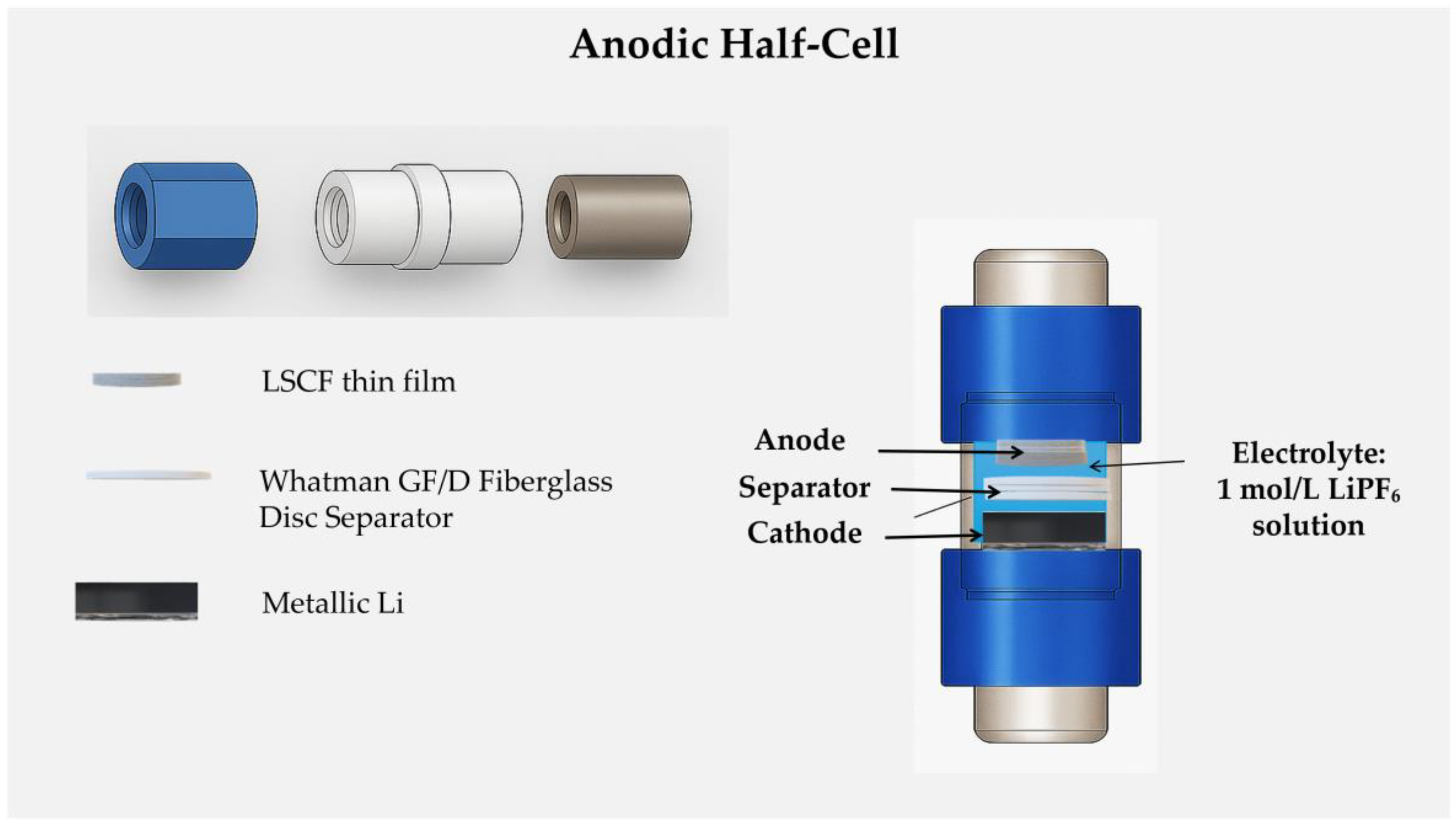
Figure 2.
X-ray diffractograms of LSCF thin films after thermal treatment at 600 °C a) in air and b) in vacuum; * corresponds to the position of the diffraction peaks of the aluminum foil substrate.
Figure 2.
X-ray diffractograms of LSCF thin films after thermal treatment at 600 °C a) in air and b) in vacuum; * corresponds to the position of the diffraction peaks of the aluminum foil substrate.
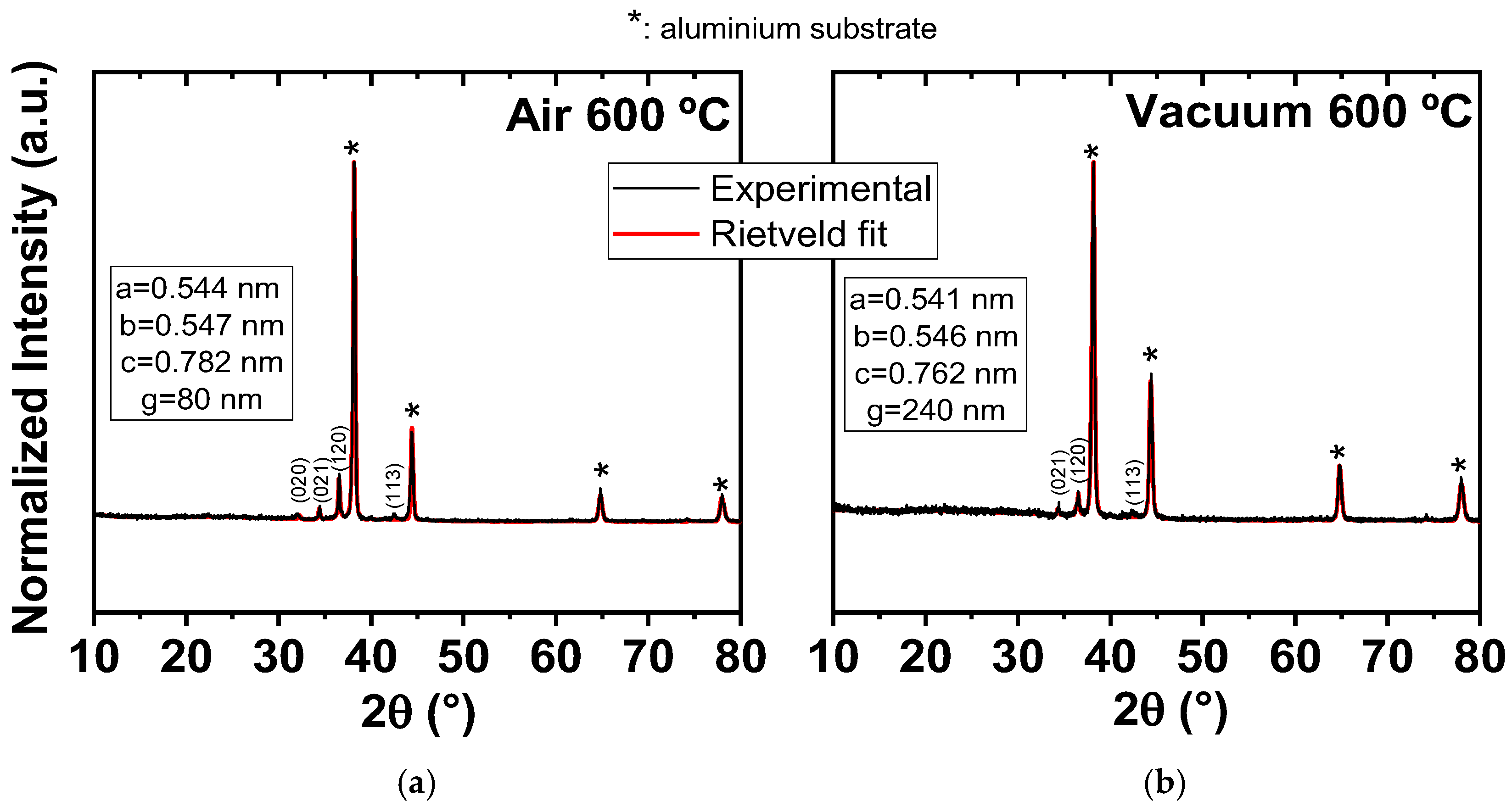
Figure 3.
Room temperature Raman spectra, normalized in intensity, referring to the as-deposited and thermal treated films at 600 °C in air and vacuum.
Figure 3.
Room temperature Raman spectra, normalized in intensity, referring to the as-deposited and thermal treated films at 600 °C in air and vacuum.
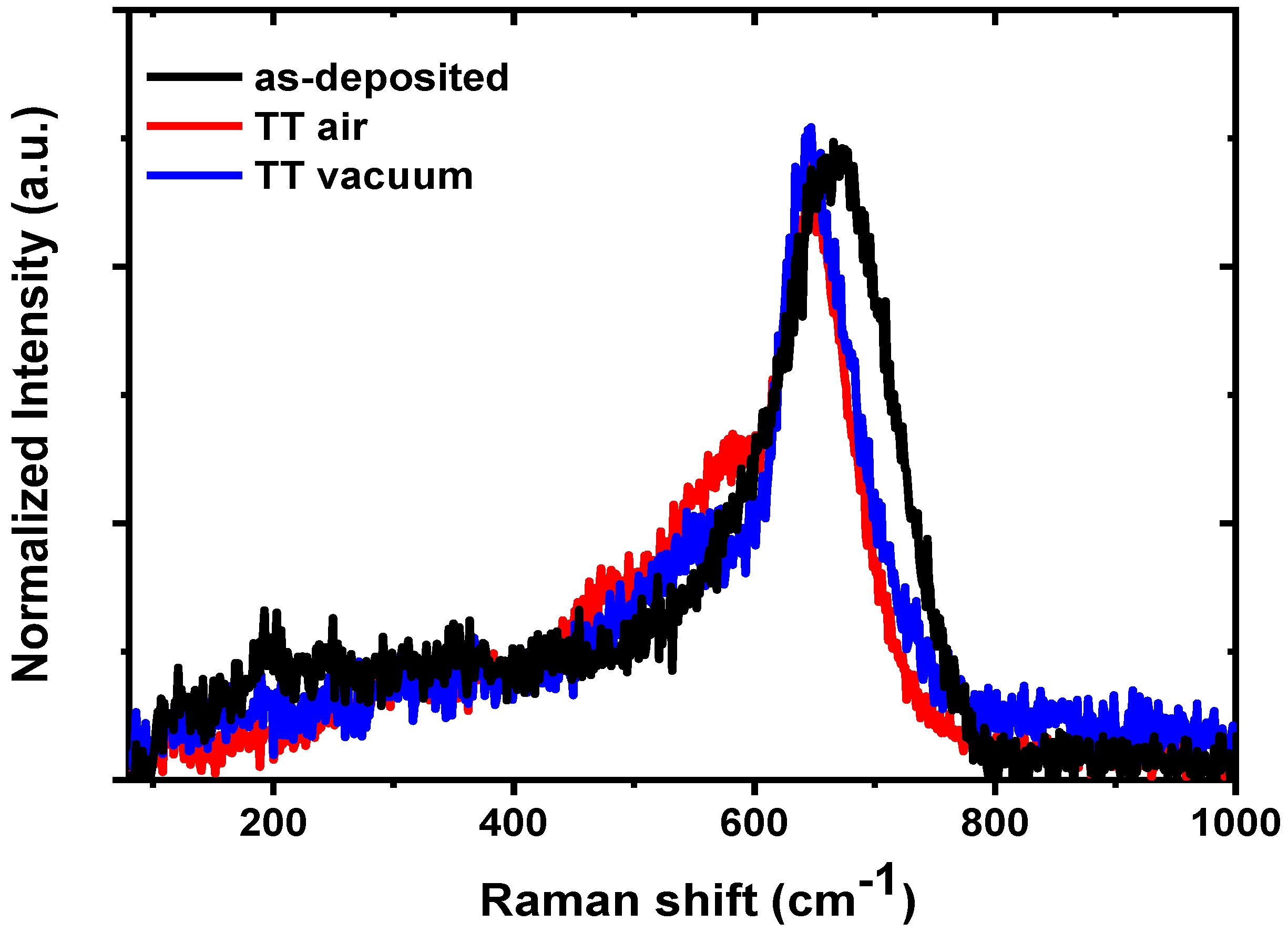
Figure 4.
SEM micrographs of the LSCF thin film surfaces for a) as-deposited, b) TT @ 600 °C in air and c) TT @ 600 °C in vacuum.
Figure 4.
SEM micrographs of the LSCF thin film surfaces for a) as-deposited, b) TT @ 600 °C in air and c) TT @ 600 °C in vacuum.
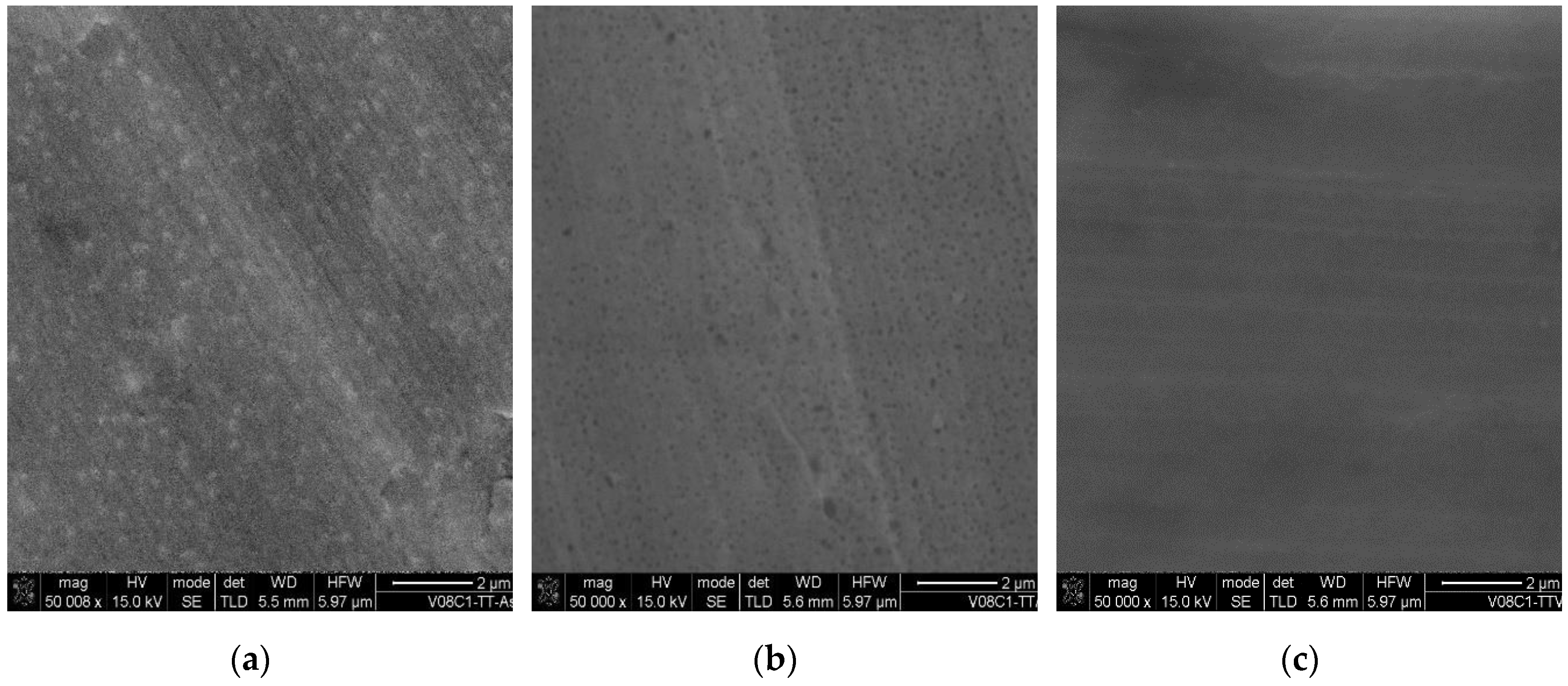
Figure 5.
Cyclic voltammograms obtained of LSCF thin films after thermal treatment at 600 °C a) in air and b) in vacuum.
Figure 5.
Cyclic voltammograms obtained of LSCF thin films after thermal treatment at 600 °C a) in air and b) in vacuum.
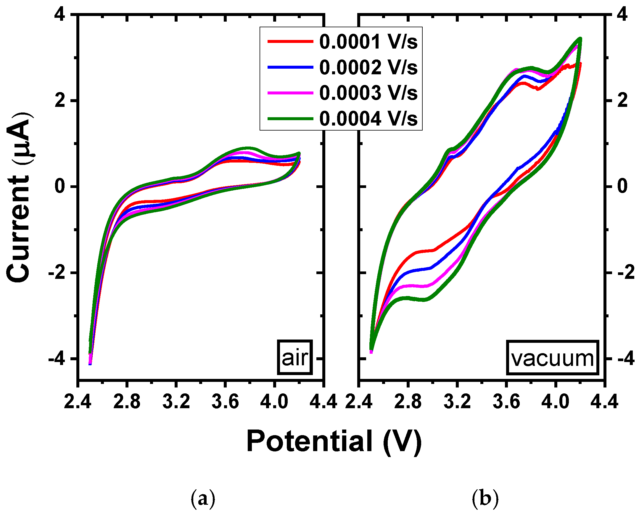
Figure 6.
Analysis of the dependence of the cathode peak current with the square root of the sweep velocity for: a) TT film at 600 °C in air, b) TT film at 600 °C in vacuum.
Figure 6.
Analysis of the dependence of the cathode peak current with the square root of the sweep velocity for: a) TT film at 600 °C in air, b) TT film at 600 °C in vacuum.
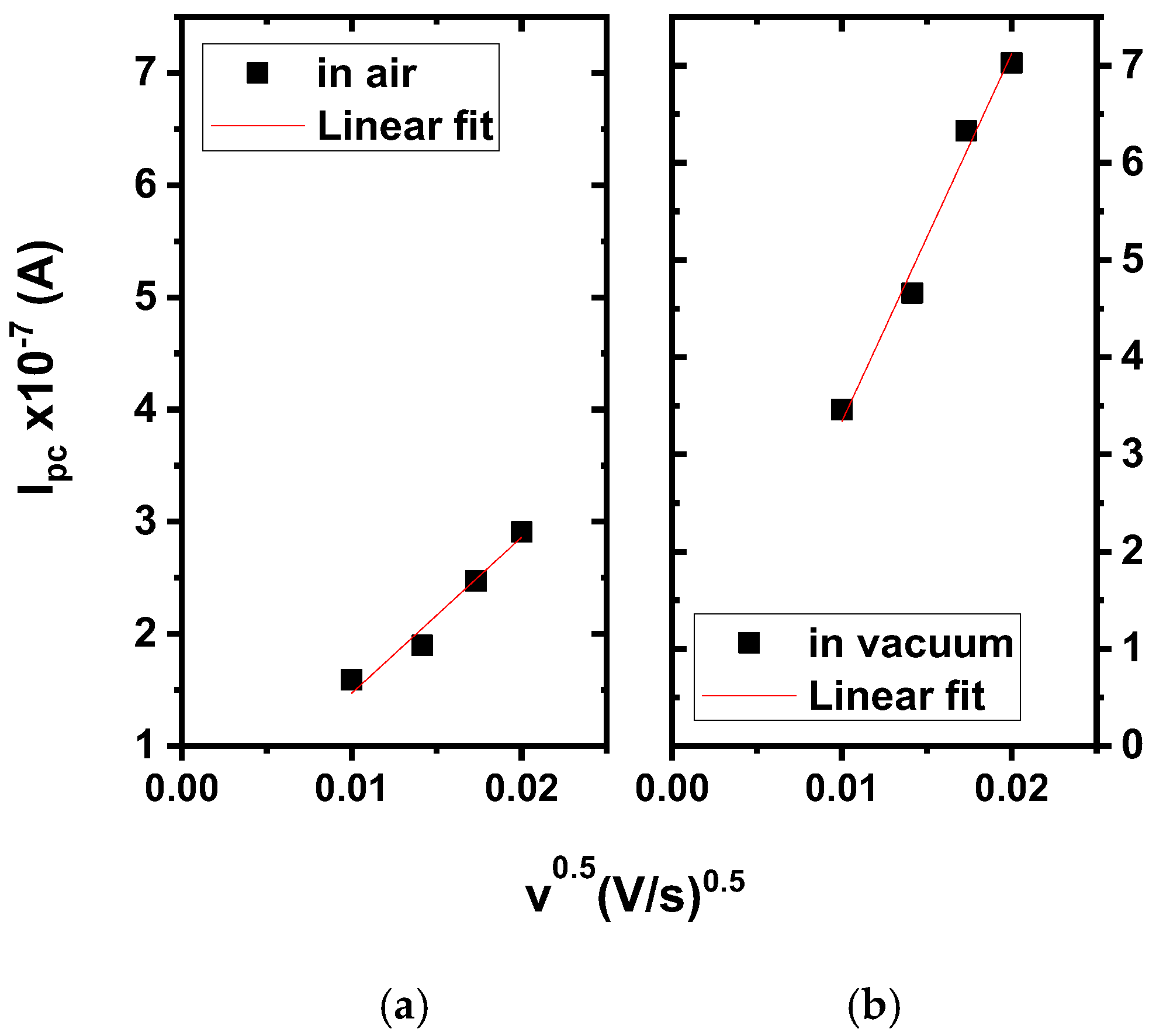
Figure 7.
Vacuum thermal treated LSCF film at 600 °C as an anode in a lithium-ion half-cell: a) charge-discharge profile, b) discharge values depending on the applied different currents.
Figure 7.
Vacuum thermal treated LSCF film at 600 °C as an anode in a lithium-ion half-cell: a) charge-discharge profile, b) discharge values depending on the applied different currents.
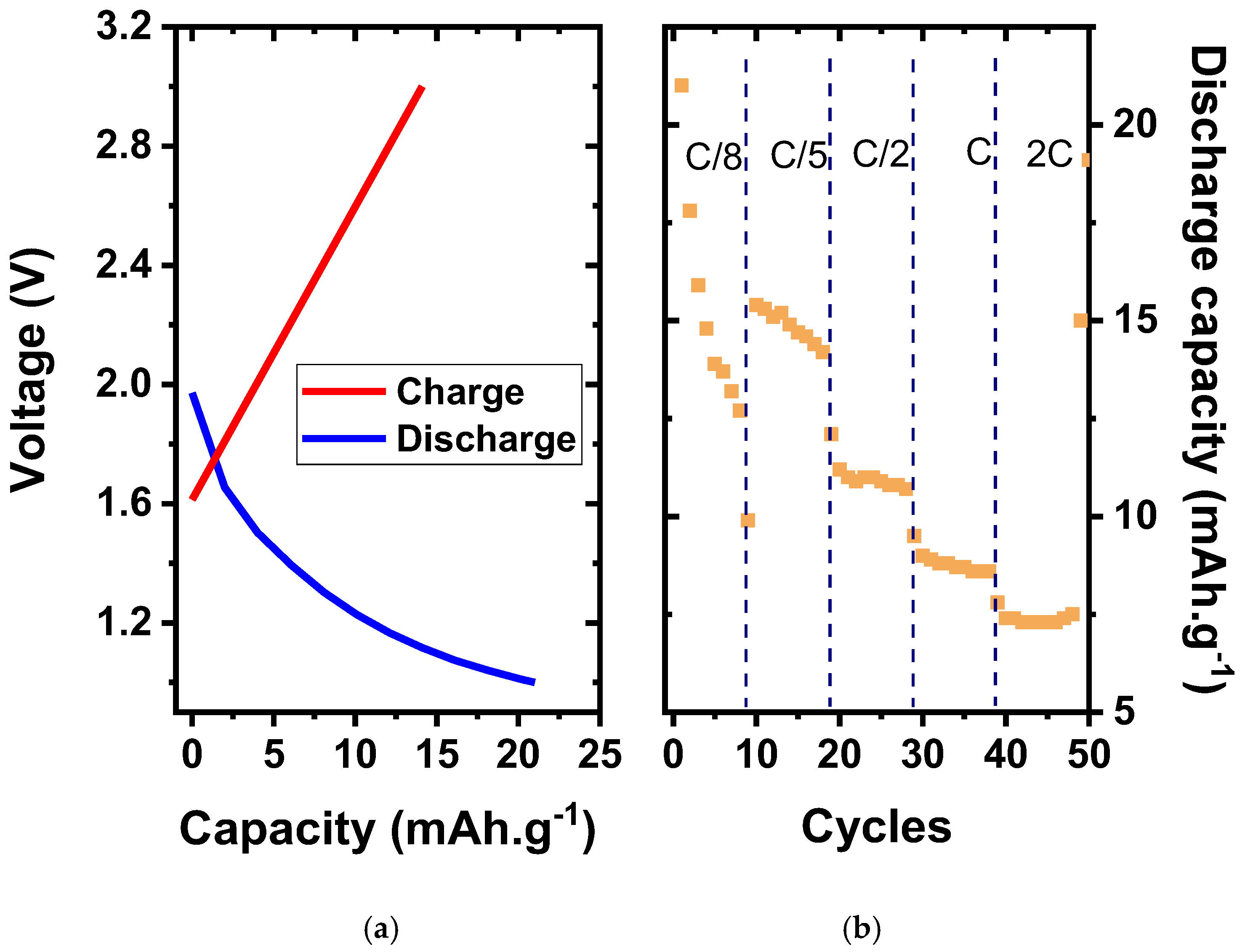
Figure 8.
a) Discharge as a function of the number of cycles and b) Nyquist curves before and after cycling, for the vacuum thermal treated LSCF film at 600 °C.
Figure 8.
a) Discharge as a function of the number of cycles and b) Nyquist curves before and after cycling, for the vacuum thermal treated LSCF film at 600 °C.
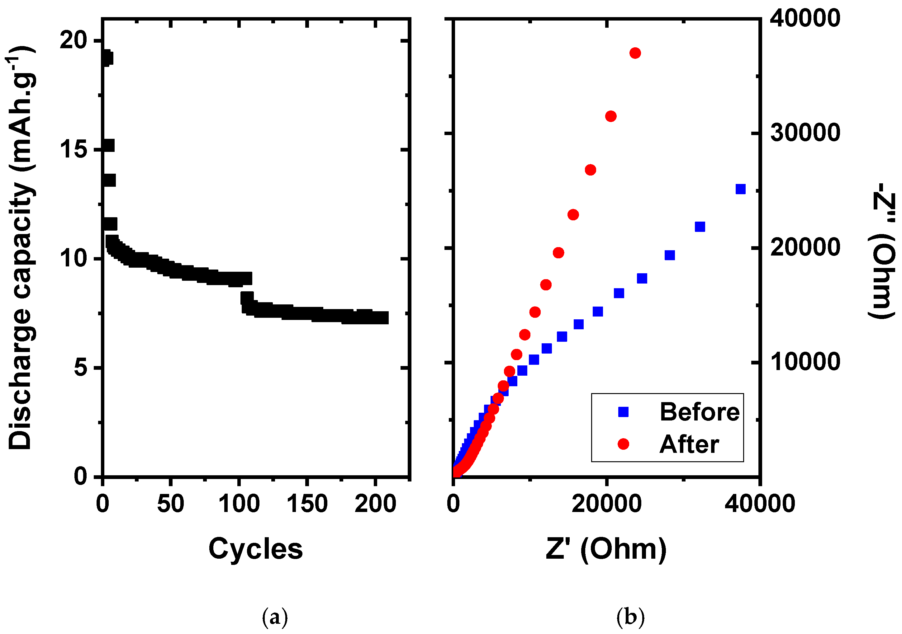
Figure 9.
Room temperature Raman spectra, normalized in intensity, referring to the vacuum thermal treated LSCF film at 600 °C prior to (red line) and after the electrochemical tests (blue line).
Figure 9.
Room temperature Raman spectra, normalized in intensity, referring to the vacuum thermal treated LSCF film at 600 °C prior to (red line) and after the electrochemical tests (blue line).
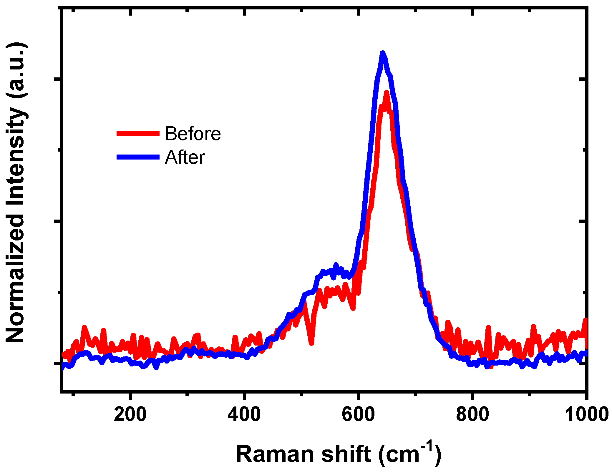

Table 1.
X-Ray diffraction Rietveld analysis data.
| Sample | Lattice parameters (nm) | Crystallite size (nm) |
|---|---|---|
| TT @ 600 °C in air | a = 0.544; b = 0.547; c = 0.782 | 80 ± 8 |
| TT @ 600 °C in vacuum | a = 0.541; b = 0.546; c = 0.762 | 240 ± 20 |
Table 2.
Atomic composition of the produced LSCF derived by EDS.
| Element | As-deposited (at. %) |
TT @ 600 °C in air (at. %) |
TT @ 600 °C in vacuum (at. %) |
|---|---|---|---|
| O | 61.49 | 53.51 | 54.57 |
| Fe | 23.67 | 28.61 | 25.79 |
| Sr | 5.28 | 4.95 | 5.07 |
| La | 7.98 | 10.48 | 11.41 |
| Co | 1.58 | 2.45 | 3.16 |
Disclaimer/Publisher’s Note: The statements, opinions and data contained in all publications are solely those of the individual author(s) and contributor(s) and not of MDPI and/or the editor(s). MDPI and/or the editor(s) disclaim responsibility for any injury to people or property resulting from any ideas, methods, instructions or products referred to in the content. |
© 2026 by the authors. Licensee MDPI, Basel, Switzerland. This article is an open access article distributed under the terms and conditions of the Creative Commons Attribution (CC BY) license (http://creativecommons.org/licenses/by/4.0/).
Copyright: This open access article is published under a Creative Commons CC BY 4.0 license, which permit the free download, distribution, and reuse, provided that the author and preprint are cited in any reuse.


