
Submitted:
09 June 2025
Posted:
10 June 2025
You are already at the latest version
Abstract
This study investigates the structure and electrochemical performance of the ZnLaFeO4 alloy as a negative electrode material in Ni-MH batteries. The alloy powder was prepared using the sol–gel hydrothermal method. The results demonstrate how the incorporation of La ions influences both the crystal structure and the electrochemical performance of the material. Structural analysis of the ZnLaFeO4 sample reveals a dominant perovskite-type phase, LaFeO3, along with two minor phases: spinel ZnFe2O4 and lanthanum (III) oxide (La2O3). The electrochemical performance of the negative electrodes was evaluated at room temperature and a C/10 rate using various techniques, including chronopotentiometry and cyclic voltammetry. The experimental results indicate that incorporating La cations into the ZnFe2O4 alloy structure, along with the emergence of the LaFeO3 phase at grain boundaries, significantly slowed down the alloy's activation process, resulting in a maximum discharge capacity of 106 mAhg⁻¹. Over extended cycling, a correlation between discharge capacity, polarization behavior, and current density evolution was observed.
Keywords:
Electrochemical kinetic characteristic
; structural properties
; hydrogen storage
; Ni-MH batteries
; Spinel ferrites
1. Introduction
Recently, mobile tools have become one of the most significant sources of pollution, consuming nearly half of the world's oil production and accounting for a quarter of global CO2 emissions [1,3]. This dramatic increase in oil resource depletion, coupled with the growing environmental awareness, has created an urgent need to develop a new model of energy-efficient and eco-friendly vehicles, such as hybrid electric vehicles (HEVs) and electric vehicles (EVs) [4,5]. The key challenge in the development of EVs and HEVs lies in battery performance [6]. As a solution, lithium-ion (Li-ion) and nickel-metal hydride (Ni-MH) batteries have emerged as the most critical onboard energy storage systems for these vehicles [7]. While lithium batteries offer the highest energy density, their low thermal stability presents significant safety concerns, particularly in the transportation sector [8,9]. On the other hand, Ni-MH batteries are widely used to reduce CO2 emissions in transportation due to their high energy density, ease of application in series, series/parallel configurations, safe charge, discharge processes, tolerance to overcharge and over-discharge, excellent thermal properties, and the use of environmentally acceptable and recyclable materials [10,16].
However, the battery performance is influenced by the intrinsic properties of the electrode materials. In Ni-MH batteries, the negative electrode acts as a hydrogen-absorbing material, where hydrogen is reversibly inserted and released during the charging and discharging processes. During charging, hydrogen is stored in the form of metal hydrides (MHₓ), and during discharging, it is released in the form of hydrogen ions that participate in the redox reaction with the positive electrode. Various metal compounds with high discharge capacities such as AB5 [17,18,19], AB2 [20], AB3 [21], AB [22], and A2B [23], have been studied since the invention of Ni-MH batteries. Despite their promising properties, these compounds are often expensive and difficult to produce, which limits their performance and viability in commercial applications. As a solution, oxide-based ABO3 compounds, (e.g., perovskite alloys) have been investigated and developed as alternatives to the intermetallic alloys used in Ni-MH batteries [24,25,26]. However, one of the primary challenges in advancing this technology is the limited operating temperature range for effective hydrogen absorption, overcome this challenges, ceramic oxide nanomaterials, including ferrites, have attracted the interest of the research community because of their distinctive crystal structures and magnetic characteristics [27,28,29]. These nanomaterials can be classified into three main types: hexaferrites, spinel ferrites, and garnets.,In fact, nano-sized spinel ferrites having the chemical formula AB2O4, where A and B occupy the tetrahedral and octahedral cation sites respectively, are the most widely utilized, due to their fascinating structural characteristics and outstanding electrical and magnetic properties [30,31,32]. This nanomaterial is extensively used in a wide range of applications, such as microwave and magnetic devices [33,34], wastewater treatment [35], sensors [36], targeted drug delivery [37], anticorrosion pigments [38,39], and optoelectronic systems [40]. It has also demonstrated promising performance as an anode material in both lithium-ion [41,42] and sodium-ion batteries [43].
Given that the properties of nano-ferrites are highly dependent on the synthesis method, several techniques (e.g., co-precipitation [44], thermal decomposition [45], solvothermal methods [46] and the sol-gel technique [47,48], etc.), were explored in previous studies, to prepare spinel ferrites. Among these, the sol-gel technique stands out for offering excellent textural characteristics, high chemical homogeneity, good crystallinity, and high purity of the final product [49].
These results have motivated research into the use of this type of nanomaterial as an electrode material in Ni-MH batteries. For instance, Wissem et al [50], synthesized zinc spinel ferrites (ZnFe2O4) using the sol-gel method and investigated them as innovative anode materials in Ni-MH batteries. The performed electrochemical characterization revealed the excellent discharge capacity (up to 145 mAh/g) and high stability during cycling.
In complementary studies [51], substitution of the A site (Zn2+) with rare-earth cations such as Sm³⁺ in the ZnxSm1-xFe2O4 system also led to interesting results, highlighting the potential of cation substitution to enhance the electrochemical properties of spinel ferrites.
Based on these results, we propose a new approach based on B-site substitution in the spinel structure, where Fe3+ is partially replaced by La3+ to form the doped compound ZnLaFeO4. This substitution is expected to modify the structure and improve electrochemical behavior by enhancing hydrogen diffusion and electrode stability.
This work aims to investigate the structural, morphological and electrochemical characteristics of ZnLaFeO4 as an innovative negative electrode material used in Ni-MH batteries.
2. Materials and Methods
2.1. Method Applied to Synthesize the Alloys
The ZnLaFeO4 powders were synthesized using a sol–gel hydrothermal process, employing stoichiometric quantities of high-purity metal nitrates: zinc nitrate hexahydrate (Zn(NO3)2·6H2O, 99.9% purity), iron nitrate nonahydrate (Fe(NO3)3·9H2O, ≥99.95% purity), and lanthanum nitrate hexahydrate (La(NO3)3·6H2O, 99.999% purity). These precursors were dissolved in demineralized water at room temperature, along with citric acid, to form a homogeneous solution. Ethylene glycol was then added to the solution under continuous stirring. After eight hours of agitation, the resulting gel was dried to remove water, Subsequently, it was ground into a fine powder. Finally, the powders were put in the oven at 900°C for 12 hours to be calcined.
2.2. Characterization Methods
A Siemens X-ray diffractometer with Ni-filtered copper radiation (λ = 1.5404 Å) was used to obtain the X-ray diffraction data of the powders at room temperature. Then the surface morphology of the alloy powder was analyzed using a scanning electron microscope (SEM).
2.2. Electrochemical Characterization
The negative electrodes were prepared applying the latex technology [52,53], which consisted in mixing 90% of the target compound with 5% carbon black and 5% polytetrafluoroethylene (PTFE). The resulting latex was, later dried under vacuum at room temperature for 24 hours. Two pieces of the dried latex were pressed onto each side of a nickel grid, which served as the current collector. Electrochemical measurements were conducted at room temperature in a three-electrode cell, where the coiled nickel wire as the auxiliary electrode, the Hg/HgO electrode and the prepared negative electrode served the reference electrode, and the working electrode, respectively. A concentrated potassium hydroxide (KOH) solution (6M) was used as the electrolyte. The negative hydride electrode was characterized by various electrochemical methods utilizing an EC-Lab potentiostat–galvanostat, All measurements performed at a C/10 rate. Chronopotentiometry was employed to evaluate the cycling properties, including the activation of the negative electrode, maximum electrochemical capacity, and polarization. This technique involves applying a constant current between the working and auxiliary electrodes while monitoring the potential change over time during a series of cycles [54] and potentiodynamic polarization which involves applying a potential E on the LaZnFe2O4 negative electrode and varying it linearly with time at a slew rate of v = 1mVs-1
3. Results
3.1. SEM Observations
Figure 1, displays the scanning electron microscopy (SEM) images show casing the microstructure of ZnLaFeO4 spinel ferrites.
The micrographs of the ZnLaFeO4 alloys show a substantial particle agglomeration, which hinders the accurate determination of grain sizes through SEM analysis.
3.2. Structural Properties
The X-ray diffractograms were refined applying the Rietveld method, drawing from the Pearson crystal structure library and using the Maud program, as illustrated in Figure 2. This technique involves fitting the calculated diffraction pattern as closely as possible to the measured data, which allowed identifying phases within the examined powder and determining of their mass proportions and lattice parameter.
The analysis of the X-ray diffraction pattern of the ZnLaFeO4 sample reveals a complex composition comprising three main phases: LaFeO3 (54.88%), La2O3 (33.23%), and ZnFe2O4 (11.89%). The predominance of LaFeO3 suggests a strong reaction between lanthanum (La) and iron (Fe) during the preparation of the sample. However, the presence of La2O3 and ZnFe2O4 phases indicates incomplete reaction, due to the uneven distribution of elements, which prevented the full formation of LaFeO3.
In their study, Chaudhary et al. [55], observed the formation of an ortho-ferrite phase. Similarly, Angari et al [56] noticed that the characteristic peaks corresponding to the LaFeO3 phase became progressively more pronounced as the concentration of La ions increased in the NiFe2O4 spinel ferrite. This observation suggests that La cations did not easily form a solid solution with the spinel ferrite, likely due to the limited solubility of La ions or their incorporation into the spinel lattice. Indeed, at high dopant concentrations (La3+), only a small fraction of La3+ cations substituted into the spinel lattice, while the excess cations accumulated at the grain boundaries, resulting in the formation of the orthoferriteLaFeO3 phase [57,58,59].
The average crystallite size (D) of the lanthanum-doped Zn-ferrite was determined using two techniques: the Debye-Scherrer method and the Williamson-Hall method.
was employed to calculate the crystallite size applying the following formula:
where k is the Scherrer’s constant, k=0.9; θ (radian) denotes the Bragg’s angle; λ represent the wavelength of the radiation CoKα and β (radian) designates the half-height width of the peaks.
The Scherrer method assumes the isotropy of the crystallites, by attributing the broadening of diffraction peaks solely to the crystallite size, while neglecting significant microstructural characteristics such as crystallographic defects or stress-induced distortions. In contrast, the Williamson-Hall method offers a more comprehensive analysis by considering that the broadening of diffraction peaks results from a combination of factors, including both the crystallite size and the micro-strain (crystallographic defects). The Williamson-Hall equation is written as follows:
The crystallite size can be determined using the intercept and slope of the linear fit from the plotted curve .
Figure 3, represents the Williamson–Hall diagrams of the ZnLaFeO4 compound
The Table 1 presents the crystallographic details of the powders determined by the Rietveld refinement analysis, including lattice parameters, phase composition, and crystallite size. The latter was measured using two different methods.
3.2. Cycling Properties of the ZnLaFeO4 Electrode Using the Galvanostatic Method
3.2.1. Activation Process of the ZnLaFeO4 Electrode
The alloy activation during electrochemical cycling is mainly determined by its maximum discharge capacity, low electrode polarization, and stable half-discharge potential. It worth-noting that some compounds activate after the first cycle, while others may require several cycles to achieve full activation.
Figure 4 shows the evolution of the discharge potential as a function of the electrochemical capacity variation of the ZnLaFeO4 electrode during the initial activation cycles in a 6 M KOH electrolyte at a C/10 rate.
The experimental results indicate that the substitution of lanthanum into the spinel structure significantly influenced the electrode's activation process. The later was slowed by the electrode's low cyclability and was only achieved after 46 cycles, with the maximum discharge capacity reaching approximately 106 mAh/g. Zayani et al [51] systematically investigated the trivalent cation subistitution in sol-gel synthesized ZnFe2O4 revealing a strong correlation between Sm³⁺ substitution levels on the A-site of the spinel ZnFe₂O₄ and electrode activation kinetics. Their work demonstrated that higher Sm3+ doping concentrations progressively hindered the activation process. In case of high-rate substitution of La (another trivalent cation) for Fe in ZnFe2O4, excess La ions are partially incorporated into the spinel structure and interact with Fe, resulting in the formation of LaFeO3 at the grain boundaries. This phenomena created a thin insulating layer around the grains, which introduced additional resistance to the charge transfer process.
To assess the reversibility of the hydrogen absorption/desorption reactions, the polarization parameter, which is the difference between the half-charge and half-discharge potentials during electrochemical cycling , was introduced This parameter can be expressed using the following equation:
Figure 5, illustrates the evolution of the half-charge/half-discharge potentials as a function of number of cycles and the polarization curve for the ZnLaFeO4 electrode.
During the first cycle before activation, the half-discharge potential of the electrode shifted to less positive values, impeding the insertion of hydrogen into the interstitial sites of the electrode. As the activation cycle progressed, the half-discharge potential became more positive, facilitating hydrogen insertion into the electrode. Initially, the polarization values varied between approximately 663 and 817 mV. This value gradually decreased to 99 mV at the activation cycle before being stabilized during the subsequent cycles. These results are consistent with the electrochemical discharge capacity data, suggesting that the hydrogen absorption/desorption reactions at the sites became more reversible during the activation cycle.
3.2.2. Cycling Properties of the ZnLaFeO4 Electrode
Figure 6 shows the evolution of the electrochemical discharge capacity as a function of the number of cycles of the ZnLaFeO4 negative electrode.
The specific discharge capacity showed a progressive increase throughout the activation cycles, reaching a maximum value of 106 mAh·g-1, as illustrated in Figure 6. While this value remains lower than that of certain oxide-based materials such as ZnFe2O4(145 mAh·g⁻¹) [50] and intermetallic compounds like LaNi₅, it still outperforms several conventional hydride materials, Ti2-xZrxNi (102 mAh·g⁻¹)[60]. This demonstrates the promising balance between performance and stability offered by the La-substituted ZnLaFeO₄.
3.2.3. Electrode Degradation Process
After several charge/discharge cycles, a decrease in capacity was commonly observed in most studied electrodes. This decrease can be explained by the first-order degradation kinetics, used to calculate the degradation rate (Kdeg). This parameter provide information about the stability of the electrochemical discharge capacity as a function of the number of cycles.
The discharge capacity (Qdischarge) and the concentration of the active material in the electrode are directly correlated for first-order degradation kinetics. This relation can be expressed as follows relationship.
where Q0 represents the maximum capacity (mAhg-1), while kdegr denotes the degradation constant of the hydride material at a specific charge/discharge rate. This constant, was derived from the slope of the linear part of the curve log(Q)=f(N), similarly to a first-order kinetic rate constant.
The following formula can be used to express the deterioration rate (kdeg), which is directly proportional to the corrosion rate (rcorr)
Figure 7, illustrates the dependence of Log (Q) on the number of cycles, showing the capacity degradation curve of the negative electrode
The maximum discharge capacity (Qdisch,max), the capacity at the 80th cycle (Q80), the retained discharge capacity (R80(%)), as well as the hydrogenation and corrosion characteristics obtained from the capacity fade curve are among the distinctive parameters summarized in Table 2
It was noticed that, after activation, the discharge capacity decreases with cycling, primarily due to the oxidation of the active surface. According to Pan et al. [61], the interactions of the working electrode with the electrolyte lead to the deterioration of the negative electrode material, which result in the decrease of the discharge capacity. The formation of corrosive byproducts, including iron (Fe) deposits that accumulate on the surface of the alloy, can be linked to this loss of capacity.It was also observed that the overall performance of the electrode was reduced because of the existence of these deposits which minimized drastically the active surface area accessible to the hydrogen absorption.
Various approaches were examined in previous studies to minimize the degradation rates. Indeed, Dymek et al. [62] investigated the degradation mechanisms of a La1.5Mg0.5Ni6.5Co0.5 electrode coated with amorphous nickel. The obtained results showed that the nickel coating considerably reduced the deterioration of the electrode, most likely by acting as a barrier to prevent corrosion and mechanical wear. In a similar aim, Bala et al. [63] focused on the efficacy of encasing electrodes in Ni-P coatings to improve the durability and minimize the deterioration. In an another study experimental results showed a significant decrease in the degradation with increasing Mn substitution levels, because of the Mn enhanced structural the stability and corrosion resistance, which prolonged the lifetime alloy and improved its performance during cycling. The above-stated research works demonstrated the important role of surface alterations and material substitution techniques in reducing the deterioration of the electrode used in electrochemical applications.
SEM micrographs obtained after cycling are shown in Figure 8.
A comparative SEM analysis was carried out between ZnFe2O4 and La-doped ZnLaFe2O4 after electrochemical cycling. SEM micrographs highlight marked morphological differences between the ZnFe2O4 and ZnLaFe2O4 samples, resulting from lanthanum incorporation.
The ZnFe2O4 sample features a compact, dense microstructure composed of strongly agglomerated micrometric grains interspersed with cracks attributable to thermomechanical stresses. Its homogeneous, low-porosity surface is characteristic of a material that has undergone high-temperature sintering or calcination.
Conversely, lanthanum doping ZnLaFe2O4 leads to a nanostructured, porous morphology, where quasi-spherical particles are irregularly dispersed. This transition to a finer, less agglomerated structure suggests that the La3+ ion disrupts crystal growth, probably due to its higher ionic radius than that of Fe3+, inducing lattice distortions and limiting grain coalescence
3.2.4. Kinetic Parameters of the ZnLaFeO4 Negative Electrode
Galvanostatic charge/discharge curves are commonly employed by researchers to determine the electrochemical discharge capacity based on the duration of each discharge cycle. However, Henryk Bala et al [64] introduced innovative methods to determine some kinetic parameters, such as the equilibrium potential and the exchange current density. Their approach involves simplifying all interfacial processes between the negative electrode and electrolyte during charging and discharging to the H2O/H2 system.
If |ic| = ia, Equation 2 was simplified to represent the midpoint of the potential jump (ΔE), resulting in the following equation:
The potentials E (+i) and E (-i) correspond to the start of the charge and the end of the discharge respectively. The Tafel slope of the straight lines on both sides (cathodic and anodic) of the hydrogen electrode is represented by b, while icharge and idischarge are the charge and discharge currents applied between the working electrode and the auxiliary electrode, respectively.
Figure 9, illustrates the variation in the equilibrium potential for the H2O/H2 system as a function of the number of cycle for the ZnLaFeO4 negative electrode.
As showed in Figure 9, the equilibrium potential of the ZnLaFeO4 electrode declines gradually with the increase in the number charge /discharge cycles. During the initial cycles, the potential shifts towards more negative values. As the number of cycles increases, the equilibrium potential gradually turns towards more positive values, resulting in a value of -0.827 V at the end of the cycling process.
The obtained findings reveal that, the ZnLaFeO4 electrode underwent an initial activation or modification, followed by a stabilization phase. It was obvious that the performance and potential of the electrode were influenced by changes in its electrochemical properties or structure during cycling.
3.2. Redox Properties of the Electrode ZnLaFeO4 Studied by Potentiodynamic Method
During the electrochemical cycling, the ZnLaFeO4 negative electrode cycling was studied by determining the voltammograms, I=f(E), using the linear voltammetry technique. Using the first Stern method and origin software, the Tafel polarization curves were drawn using the obtained voltammograms.
Figure 10 shows the progression of both experimental and theoretical Tafel curves for ZnLaFeO4 negative electrodes during cycling.
As illustrated in Figure 10, the Tafel polarization curves of the ZnLaFeO4 electrode exhibit minimal variation during the initial cycles, indicating stable electrochemical behavior. However, a distinct shift appears around the 46th activation cycle, with the curves moving toward more positive potentials values. This change suggests that the activation process improves the electrode's ability to facilitate hydrogen insertion, likely due to increased surface activity and a greater number of active sites. After this activation process, the Tafel curves gradually shift back toward less positive potentials values, indicating a reduction in hydrogen insertion efficiency. This behavior may be attributed to a decline in surface reactivity or a partial saturation of active sites, which makes hydrogen incorporation more difficult.
Adjusting the theoretical Butler-Volmer equation to the Tafel polarization curves allowed determining the of redox variables, such as the current density and the Nernst potential [67].
Figure 11 depicts the progress of the Nernst potential (E0) as the ZnLaFeO4 electrode underwent multiple charge/discharge cycles.
It was observed that the Nernst potential of the electrode increased during the activation cycles of the electrode increased during the activation cycle and shifted toward less negative values, It reached k its maximum value on the 40th cycle. due to the fast insertion of hydrogen into the electrodes, especially during the activation process. After this activation phase, the Nernst potential shifted to more negative values, indicating that hydrogen insertion became more difficult due to the deterioration of the active material through oxidation [51].
Figure12, demonstrates the variation of the exchange current density I0 as a function of the number of cycles of the ZnLaFeO4 electrode.
As showed in Figure12 during cycling the exchange current density of the ZnLaFeO4 electrode shows the same evolution as the electrochemical discharge capacity. As the activation cycles proceeded, the exchange current density of the ZnLaFeO4 electrode increased and reached its highest values. This rise can be explained by the improved hydrogen adsorption occurring at the electrode-electrolyte interface during cycling. However, achieving the maximum value required more cycles because the LaFeO3 phase, which appeared at the grain boundaries, had poor intrinsic conductivity.
It was also noticed that the current density of the ZnLaFeO4 electrode’s decreased due to corrosion after activation, which resulted in fewer interstitial sites available for hydrogen insertion.
5. Conclusions
Due to its simplicity and cost-effectiveness, the sol-gel method was used to synthesize the ZnLaFeO4 compound.
Structural analysis revealed a multiphase composition in the synthesized ZnLaFeO4 material, consisting of a spinel structure accompanied by LaFeO3 and La2O3 secondary phases. The electrochemical behavior of the electrode was investigated using techniques such as chronoamperometry and cyclic voltammetry. The activation process was relatively slow, with the maximum discharge capacity of 106 mAh/g achieved only after 46 cycles. This sluggish activation is likely due to structural rearrangements.
The gradual decrease in discharge capacity after activation process, was attributed to mechanical degradation of the electrode, particularly cracking and fracturing caused by volumetric expansion and contraction during charge/discharge cycles. These defects likely contributed to the loss or detachment of active material, thereby reducing the number of electrochemically accessible sites.
A strong correlation was observed between discharge capacity, polarization, and current density throughout cycling. The high La3+ concentration was found to destabilize the spinel structure, facilitating the emergence of the LaFeO3 perovskite phase. This structural transformation negatively affected both the integrity and the electrochemical performance of the electrode.
Compared to analogous compounds, the ZnLaFeO4 alloy developed in this study demonstrates significantly enhanced electrochemical performance. Undoped ZnFe2O4, for instance, commonly suffers from low discharge capacity and poor cycling stability due to its limited electrical conductivity and inherent structural limitations. Similarly, while LaFeO3 is known for its chemical stability, its perovskite structure is not well-suited for hydrogen storage, leading to suboptimal performance in Ni-MH batteries. In contrast, the ZnLaFeO4 compound exhibits a maximum discharge capacity of 106 mAh/g along with stable cycling behavior. These improvements underscore the beneficial role of La doping, which appears to enhance charge transport and corrosion resistance within the spinel structure. Overall, ZnLaFeO4 emerges as a promising candidate for use as an anode material in Ni-MH battery systems.
Future work will focus on a more controlled and gradual substitution of La3+ into the spinel lattice, to investigate its effects on the structural stability, and overall electrochemical performance of the material.
References
- Gielen, D.; Boshell, F.; Saygin, D.; Bazilian, M.D.; Wagner, N.; Gorini, R. The role of renewable energy in the global energy transformation. Energy. strat. Reviews. 2019. 24, 38-50. [CrossRef]
- Campanari, S.; Manzolini, G.; De la Iglesia, F. G. Energy analysis of electric vehicles using batteries or fuel cells through well-to-wheel driving cycle simulations. J. Power Sou. 2009, 186(2) 464-477. [CrossRef]
- Smith,W.J. Can EV (electric vehicles) address Ireland’s CO2 emissions from transport? Energy. 2010. 35(12), 4514-4521. [CrossRef]
- Sun, F.; Hu, X.; Zou, Y. ; Li, S. Adaptive unscented Kalman filtering for state of charge estimation of a lithium-ion battery for electric vehicles. Energy. 2011, 36(5), 3531-3540. [CrossRef]
- Johansson, B.; Mårtensson, A. Energy and environmental costs for electric vehicles using CO2-neutral electricity in Sweden. Energy. 2000. 25(8), 777-792 . [CrossRef]
- Chau, K. T. ;.Wu, K. C. ; Chan, C. C. A new battery capacity indicator for lithium-ion battery powered electric vehicles using adaptive neuro-fuzzy inference system. Energy. Conver.Manag. 2004. 45(11-12),1681-169 . [CrossRef]
- Rao, Z.; Wang, S. A review of power battery thermal energy management. Renew. Sustai. Energy.Rev. 2011. 15(9),4554-4571. [CrossRef]
- Kang, J.; Yan, F.; Zhang, P. ; Du, C. Comparison of comprehensive properties of Ni-MH (nickel-metal hydride) and Li-ion (lithium-ion) batteries in terms of energy efficiency. Energy. 2014, 70, 618-625. [CrossRef]
- Niu, H. ; Zhang, N. ; Lu, Y. ; Zhang, Z. ; Li, M. ; Liu, J.; Zhang, N.; Song, W.; Zhao Y.; Miao, Z. Strategies toward the development of high-energy-density lithium batteries. J. Energy Storage, 2024. 88, 111666 . [CrossRef]
- Fetcenko, M. A.; Ovshinsky, S. R.; Reichman, B.; Young, K.; Fierro, C.; Koch, J.;Zallen, A. ; Mays, W.; Ouchi, T. Recent advances in NiMH battery technology. J.Power Sou. 2007. 165(2), 544-551. [CrossRef]
- Guo, Y.; Wang, W. ; Su, H. ; Lu, H. ; Li, Y.; Peng, Q.; Shumin H.; Zhang, L. Insights into the effect of Y substitution on superlattice structure and electrochemical performance of A5B19-type La-Mg-Ni-based hydrogen storage alloy for nickel metal hydride battery.J Mater Sci Technol.2025. 207, 60-69. [CrossRef]
- Salighe, Z.; Arabi, H.; Ghorbani, S.; Komeili, M. Microstructural, hydrogenation and electrochemical properties of La2Mg1-xYxNi10Mn0. 5 (x= 0.1, 0.38) alloys for Ni-MH battery anode. J. Solid State Chem. 2025. 348, 125340. [CrossRef]
- Zhang, Q. ; Bian, Z. ; Liu, X. ; Lan, X. ; Liu, J. ; Ma, Z. ; Zhang, H. ; Luo, Y. Effects of thickness and gas hydrogenation on the electrochemical performances of a-Si thin film as anode for Ni-MH battery. Int J Hydrogen Energy. 2024. 82, 959-967. [CrossRef]
- Sun, W.; Sheng, P.; Zhang, X.; Sun, H.; Li, J.; Cao, Z., Qi, Y.; Zhang, Y. Metal Hydride Electrodes Applied to Ni-MH Battery Using Mg-Y-Ni-Cu-Based Alloys. Energy Technology. 2025. 2402252. [CrossRef]
- Marins, A. A.; Boasquevisque, L. M.; Muri, E. J.; Freitas, M. B. Enviromentally friendly recycling of spent Ni–MH battery anodes and electrochemical characterization of nickel and rare earth oxides obtained by sol–gel synthesis. Mater. Chemi. Phys. 2022. 280, 125821. [CrossRef]
- Zhang, Y. H.; Wei, X.; Gao, J. L.; Hu, F.; Qi, Y.; Zhao, D. L. Electrochemical hydrogen storage behaviors of as-milled Mg–Ti–Ni–Co–Al-based alloys applied to Ni-MH battery. Electro .Acta. 2020. 342, 136123 . [CrossRef]
- Kalita, G.; Otsuka, R.; Endo, T.; Furukawa, S. Recent advances in substitutional doping of AB5 and AB2 type hydrogen storage metal alloys for Ni-MH battery applications. J Alloys Compd. 2025.179352. [CrossRef]
- Ouyang, L.; Huang, J.; Wang, H.; Liu, J.; Zhu, M. Progress of hydrogen storage alloys for Ni-MH rechargeable power batteries in electric vehicles: A review. Mater. Chem.Phy. 2017.200, 164-178. [CrossRef]
- Joubert, J. M. ; Paul-Boncour, V.; Cuevas, F.; Zhang, J. ; Latroche, M. LaNi5 related AB5 compounds: Structure, properties and applications. J.Alloys. Comp. 2021. 862, 158163. [CrossRef]
- Gamo, T.; Moriwaki, Y.; Yanagihara, Yamashita, T.; Iwaki, T. Formation and properties of titanium-manganese alloy hydrides. Int.J.Hydr. Ener. 1985. 10(1), 39-47. [CrossRef]
- Chen, J.; Takeshita, H. T. ; Tanaka, H.; Kuriyama, N. ; Sakai, T.; Uehara, I.; Haruta, M. Hydriding properties of LaNi3 and CaNi3 and their substitutes with PuNi3-type structure. J.Alloys . Comp. 2000. 302(1-2), 304-313. [CrossRef]
- Cuevas, F.; Joubert, J. M.; Latroche, M.; Percheron-Guegan, A. Intermetallic compounds as negative electrodes of Ni/MH batteries. App. Phys. A. 2001. 72, 225-238.https://link.springer.com/article/10.1007/s003390100775#citeas.
- Arya, S.; Verma, S. Nickel-metal hydride (Ni-MH) batteries. Rechar. Batteries: Histo. Prog. Appli. 2020. 131-175 . [CrossRef]
- Jin, S.; Ren, K.; Liang, J.; Kong, J. A novel sheet perovskite type oxides LaFeO3 anode for nickel-metal hydride batteries. J Mater Sci Technol. 2024. 195, 218-226. [CrossRef]
- Esaka, T.; Sakaguchi, H.; Kobayashi, S. Hydrogen storage in proton-conductive perovskite-type oxides and their application to nickel–hydrogen batteries. Solid .State Ioni. 2004. 166(3-4), 351-357. [CrossRef]
- Stoumpos, C. C.; Kanatzidis, M. G. Halide Perovskites: poor Man's high-performance semiconductors. Adv. Mater .2016.28(28), 5778-5793. [CrossRef]
- M.Bini, M.Ambrosetti , D.Spada, ZnFe2O4, a green and high-capacity anode material for lithium-ion batteries: A review. Appl. Sci. 2021. 11(24), 11713. [CrossRef]
- Brabers, V. A. M. Progress in spinel ferrite research. Hand.mag.mater. 1995. 8, 189-324. [CrossRef]
- Narang, S. B. ; Pubby, K. Nickel spinel ferrites: a review. J. Mag. Mag. Mater. 2021. 519, 167163. [CrossRef]
- Thakur, D.; Latwal, M.; Singh, J.P.; K.Gupta, L.; Srivastava, R .C. 9 - Zinc ferrite nanoparticles and their biomedical applications. Woodhead Publishing .Ox .Med.Appl. 2023. 233-255. [CrossRef]
- Valenzuela, R. Novel applications of ferrites. Phys.Resea. Int . 2012(1), 591839 (2012). [CrossRef]
- Yadav, R. S.; Kuřitka, I.; Vilcakova, J.; Urbánek, P.; Machovsky, M.; Masař, M.; Holek, M. Structural, magnetic, optical, dielectric, electrical and modulus spectroscopic characteristics of ZnFe2O4 spinel ferrite nanoparticles synthesized via honey-mediated sol-gel combustion method. J.Phys.Chem.Solids. 2017.110, 87-99. [CrossRef]
- Baykal, A.; Kasapoğlu, N.; Durmuş, Z.; Kavas, H.; Toprak, M. S.; Köseoğlu, Y. CTAB-Assisted Hydrothermal Synthesis and Magnetic Characterization of NixCo{1-x} Fe2O4 Nanoparticles (x= 0.0, 0.6, 1.0). Turkish. J. chem. 2009.33(1), 33-45. [CrossRef]
- Selvan, R. K. ; Krishnan, V.; Augustin, C. O.; Bertagnolli, H.; Kim, C. S.; Gedanken, A.Investigations on the structural, morphological, electrical, and magnetic properties of CuFe2O4− NiO nanocomposites. Chem. Mater. 2008. 20(2), 429-439. [CrossRef]
- Kefeni, K. K.; Mamba, B. B.; Msagati, T. A. Application of spinel ferrite nanoparticles in water and wastewater treatment: a review. Sepa. Pur. Tech. 2017.188, 399-422. [CrossRef]
- Šutka, A.; Gross, K. A. Spinel ferrite oxide semiconductor gas sensors. Sens. actuators B: chem. 2016.222, 95-105. [CrossRef]
- Lima-Tenório, M. K. ; Tenório-Neto, E. T.; Hechenleitner, A. A. W.; Fessi, H.; Pineda, E. A. G. CoFe2O4 and ZnFe2O4 nanoparticles: an overview about structure, properties, synthesis and biomedical applications. J. Coll. Sci. 2016. Biotech.5(1), 45-54. [CrossRef]
- Amini, M. M.; Yadavi, M. Influence of metal core of mixed-metal carboxylates in preparation of spinel: ZnFe2O (O2CCF3) 6 as a single-source precursor for preparation of ZnFe2O4. Appl. Organo. Chem.2005. 19(11), 1164-1167. [CrossRef]
- Kalendova, A.; Veselý, D.; Brodinova, J. Anticorrosive spinel-type pigments of the mixed metal oxides compared to metal polyphosphates. Anti-Corr. Meth. Mater. 2004. 51(1), 6-17. [CrossRef]
- Dhineshbabu, N. R.; Vettumperumal, R.; Narendrakumar, A.; Manimala, M. ; Kanna, R. R. ; Optical properties of lanthanum-doped copper spinel ferrites nanoparticles for optoelectronic applications. Adv. Sci. Enginee. Med.2017. 9(5), 377-383. [CrossRef]
- Mujahid, M.; Khan, R. U.; Mumtaz, M.; Soomro, S. A.; Ullah, S. NiFe2O4 nanoparticles/MWCNTs nanohybrid as anode material for lithium-ion battery. Cer.Int.2019. 45(7), 8486-8493. [CrossRef]
- Lavela, P. ; Tirado, J. L. CoFe2O4 and NiFe2O4 synthesized by sol–gel procedures for their use as anode materials for Li ion batteries. J. Pow. Sou. 2007. 172(1), 379-387. [CrossRef]
- Kumar, P. R.; H.Jung, Y.; Bharathi, K. K.; Lim, C. H. ; Kim, D. K. High capacity and low cost spinel Fe3O4 for the Na-ion battery negative electrode materials. Elect. Acta. 2014.146, 503-510. [CrossRef]
- Shenoy, S. D.; Joy, P. A.; Anantharaman, M. R. Effect of mechanical milling on the structural, magnetic and dielectric properties of coprecipitated ultrafine zinc ferrite. J.Mag. Mag. Mater. 2004. 269(2), 217-226 . [CrossRef]
- Yao, C.; Zeng, Q.; Goya, G. F.; Torres, T.; Liu, J.; Wu, H.; Ge, M.; Zeng, Y.;Wang, Y. ; Jiang, J. Z. ZnFe2O4 nanocrystals: synthesis and magnetic properties. J. Phy. Chem. 2007.111(33), 12274-12278. [CrossRef]
- Rameshbabu, R.; Ramesh, R.; Kanagesan, S.; Karthigeyan, A.; Ponnusamy, S. Synthesis and study of structural, morphological and magnetic properties of ZnFe 2 O 4 nanoparticles. J. Super. Novel Mag. 2014. 27, 1499-1502. [CrossRef]
- Haija, M. A.; Abu-Hani, A. F. ; Hamdan, N.; Stephen, S.; Ayesh, A. I. Characterization of H2S gas sensor based on CuFe2O4 nanoparticles. J. Alloys. Comp. 2017. 690, 461-8. [CrossRef]
- Soussi, A.; Haounati, R.; Taoufiq, M.; Baoubih, S.; Jellil, Z.; Elfanaoui, A.; Ihlal, A. Investigating structural, morphological, electronic, and optical properties of SnO2 and Al-doped SnO2: A combined DFT calculation and experimental study. Physica B: Condens. Matter. 2024. 690, 416242. [CrossRef]
- Renuka, L.; Anantharaju, K. S.; Sharma, S. C.; Vidya, Y. S.; Nagaswarupa, H. P.; Prashantha, S. C. ; Nagabhushana, H. Synthesis of ZnFe2O4 nanoparticle by combustion and sol gel methods and their structural, photoluminescence and photocatalytic performance. Mater. Today: Procee. 2018. 5(10), 20819-20826. [CrossRef]
- Zayani, W.; Azizi, S.; El-Nasser, K. S.; Othman Ali, I.; Molière,M.; Fenineche, N. ; Mathlouthi, H.; Lamloumi, J. Electrochemical behavior of a spinel zinc ferrite alloy obtained by a simple sol-gel route for Ni-MH battery applications. Int. J. Ener.Resea. 2021.45(4), 5235-5247. [CrossRef]
- Zayani, W., Azizi, S., El-Nasser, K. S., Belgacem, Y. B., Ali, I. O., Fenineche, N., Mathlouthi, H. New nanoparticles of (Sm, Zn)-codoped spinel ferrite as negative electrode in Ni/MH batteries with long-term and enhanced electrochemical performance. Int J Hydrog Energy. 2019. 44(22), 11303-11310. [CrossRef]
- Epp, J. X-ray diffraction (XRD) techniques for materials characterization. Woodhead Publishing. Mater. Chara.using nondes. Evalua. (NDE) Meth. 2016. 81-124. [CrossRef]
- Huang, L. W.; Elkedim, O.; Moutarlier, V. Synthesis and characterization of nanocrystalline Mg2Ni prepared by mechanical alloying: Effects of substitution of Mn for Ni. J. Alloys. Comp. 2010. 504, S311-S314. [CrossRef]
- Karaoud, I.; Dabaki, Y.; Khaldi, C.; ElKedim, O.; Fenineche, N.; Lamloumi, J. Electrochemical properties of the CaNi4. 8M0. 2 (M= Mg, Zn, and Mn) mechanical milling alloys used as anode materials in nickel-metal hydride batteries. Environ. Prog. Sus. Energy. 2023. 42(5), e14118 (2023). [CrossRef]
- Chaudhari, V.; Shirsath, S. E.; Mane, M. L.; Kadam, R. H.; Shelke, S. B.; Mane, D. R. Crystallographic, magnetic and electrical properties of Ni0. 5Cu0. 25Zn0. 25LaxFe2− xO4 nanoparticles fabricated by sol–gel method. J. Alloys. Comp. 2013. 549, 213-220. [CrossRef]
- Al Angari, Y. M. Magnetic properties of La-substituted NiFe2O4 via egg-white precursor route. J. Mag. Mag. Mater. 2011.323(14), 1835-1839. [CrossRef]
- Aslam, A.; Rehman, A. U.; Amin, N.; un Nabi, M. A.; ul ain Abdullah , Q.; Morley, N. A.; Mehmood, K. Lanthanum doped Zn0. 5Co0. 5LaxFe2− xO4 spinel ferrites synthesized via co-precipitation route to evaluate structural, vibrational, electrical, optical, dielectric, and thermoelectric properties. J. Phy. Chem. Solids. 2021. 154, 110080. [CrossRef]
- Wang, Y.; Xu, F.; Li, L. ; Liu, H.; Qiu, H.; Jiang, J. Magnetic properties of La-substituted Ni–Zn–Cr ferrites via rheological phase synthesis. Mater. Chem. Phys. 2008. 112(3), 769-773. [CrossRef]
- Ganure, K. A.; Dhale, L. A.; Katkar, V. T.; Lohar, K. S. Synthesis and characterization of lanthanum-doped Ni-Co-Zn spinel ferrites nanoparticles via normal micro-emulsion method. Int. J. Nanotechnol. Appl. 2017. 11(2), 189-195.
- Li, X. D., Elkedim, O., Nowak, M., Jurczyk, M., & Chassagnon, R. Structural characterization and electrochemical hydrogen storage properties of Ti2− xZrxNi (x= 0, 0.1, 0.2) alloys prepared by mechanical alloying. Int J Hydrog Energy. 2013. 38(27), 12126-12132. [CrossRef]
- Pan, Y. H.; Srinivasan, V.; Wang, C. Y. An experimental and modeling study of isothermal charge/discharge behavior of commercial Ni–MH cells. J. Power. Sour. 2002. 112(1), 298-306 (2002). [CrossRef]
- Dymek, M.; Nowak, M.; Jurczyk, M.; Bala, H. Encapsulation of La1. 5Mg0. 5Ni7 nanocrystalline hydrogen storage alloy with Ni coatings and its electrochemical characterization. J.Alloys.Comp. 2018.749,534-542. [CrossRef]
- Bala, H.; Dymek, M. Corrosion degradation of powder composite hydride electrodes in conditions of long-lasting cycling. Mater. Chem. Phys.167, 265-270 (2015). [CrossRef]
- Bala, H. ; Giza, K. ; Kukula, I. Determination of hydrogenation ability and exchange current of H 2 O/H 2 system on hydrogen-absorbing metal alloys. J. App. Elec. 2010. 40, 791-797(2010). [CrossRef]
- Bala, H.; Dymek, M. ; Adamczyk, L. ; Giza, K.; Drulis, H. Hydrogen diffusivity, kinetics of H 2 O/H 2 charge transfer and corrosion properties of LaNi 5-powder, composite electrodes in 6 M KOH solution. J. Solid.State Electr. 2014. 18, 3039-3048. [CrossRef]
- Bala, H.; Kukuła, I.; Giza, K.; Marciniak, B.; Różycka-Sokołowska, E.; Drulis, H. Evaluation of electrochemical hydrogenation and corrosion behavior of LaNi5-based materials using galvanostatic charge/discharge measurements. Int. J. Hydro. Energy. 2012. 37(22), 16817-16822. [CrossRef]
- Ren, K.; Miao, J.; Shen, W.; Su, H.; Pan, Y.; Zhao, J.; Han, S. High temperature electrochemical.
Figure 1.
SEM Micrograph of ZnLaFeO4.
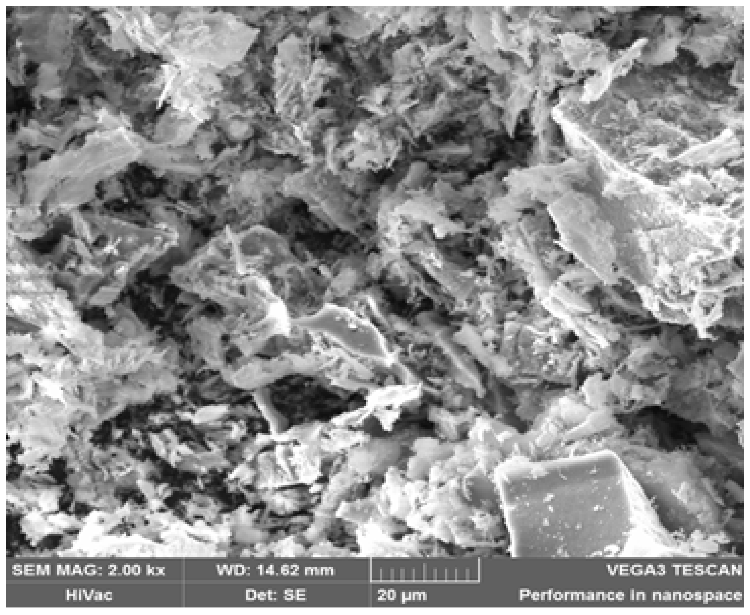
Figure 2.
X-ray diffractograms refined by the Rietveld method of ZnLaFeO4 powder synthesized by Sol-Gel method calcined at 900°C.
Figure 2.
X-ray diffractograms refined by the Rietveld method of ZnLaFeO4 powder synthesized by Sol-Gel method calcined at 900°C.
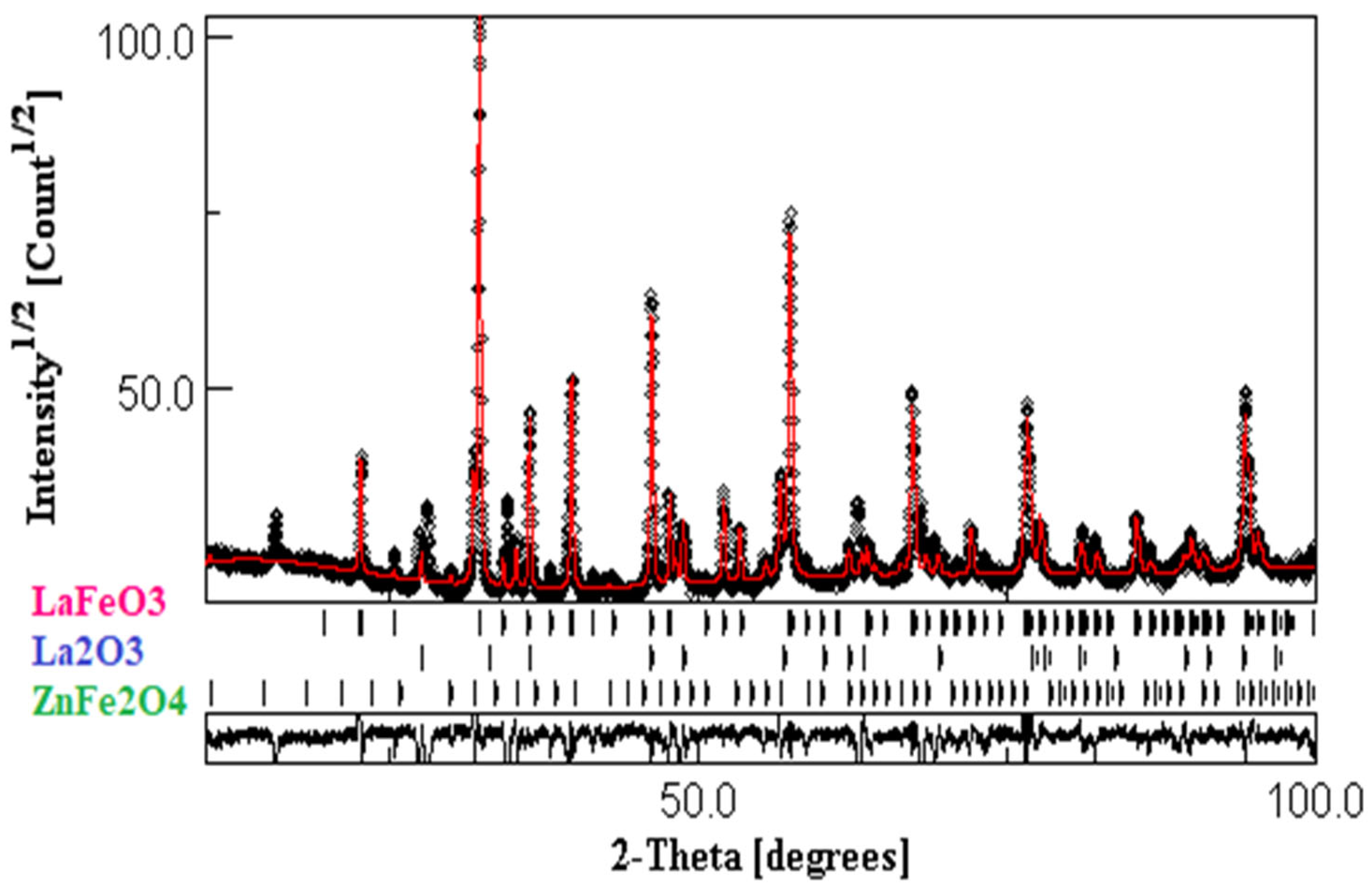
Figure 3.
The Williamson–Hall diagrams of the ZnLaFeO4 compound.
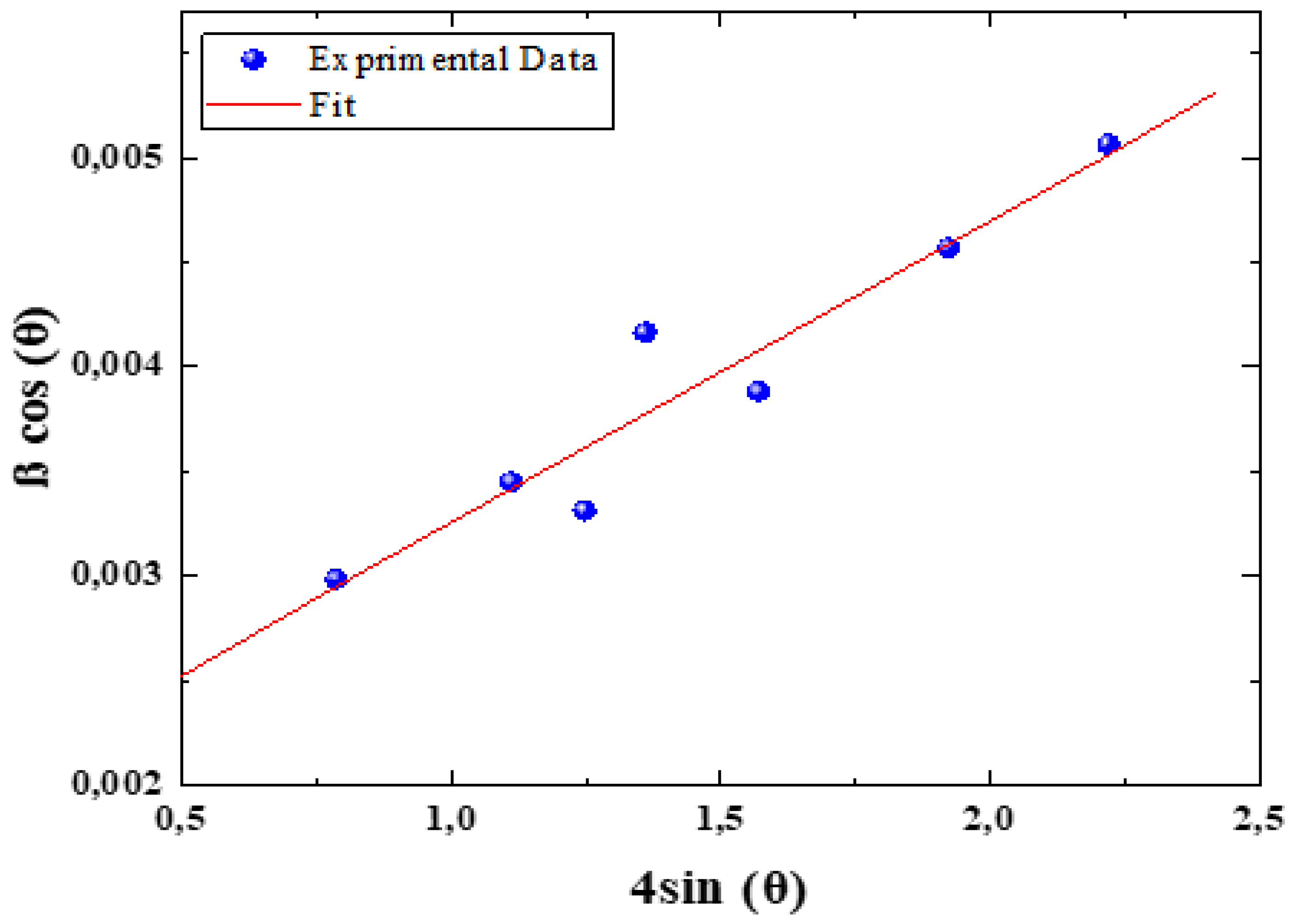
Figure 4.
Evolution of the discharge potential curves as a function of the variation of the discharge capacity of the ZnLaFeO4 electrode during the first activation cycles, and at a discharge current of 0.8mA.
Figure 4.
Evolution of the discharge potential curves as a function of the variation of the discharge capacity of the ZnLaFeO4 electrode during the first activation cycles, and at a discharge current of 0.8mA.
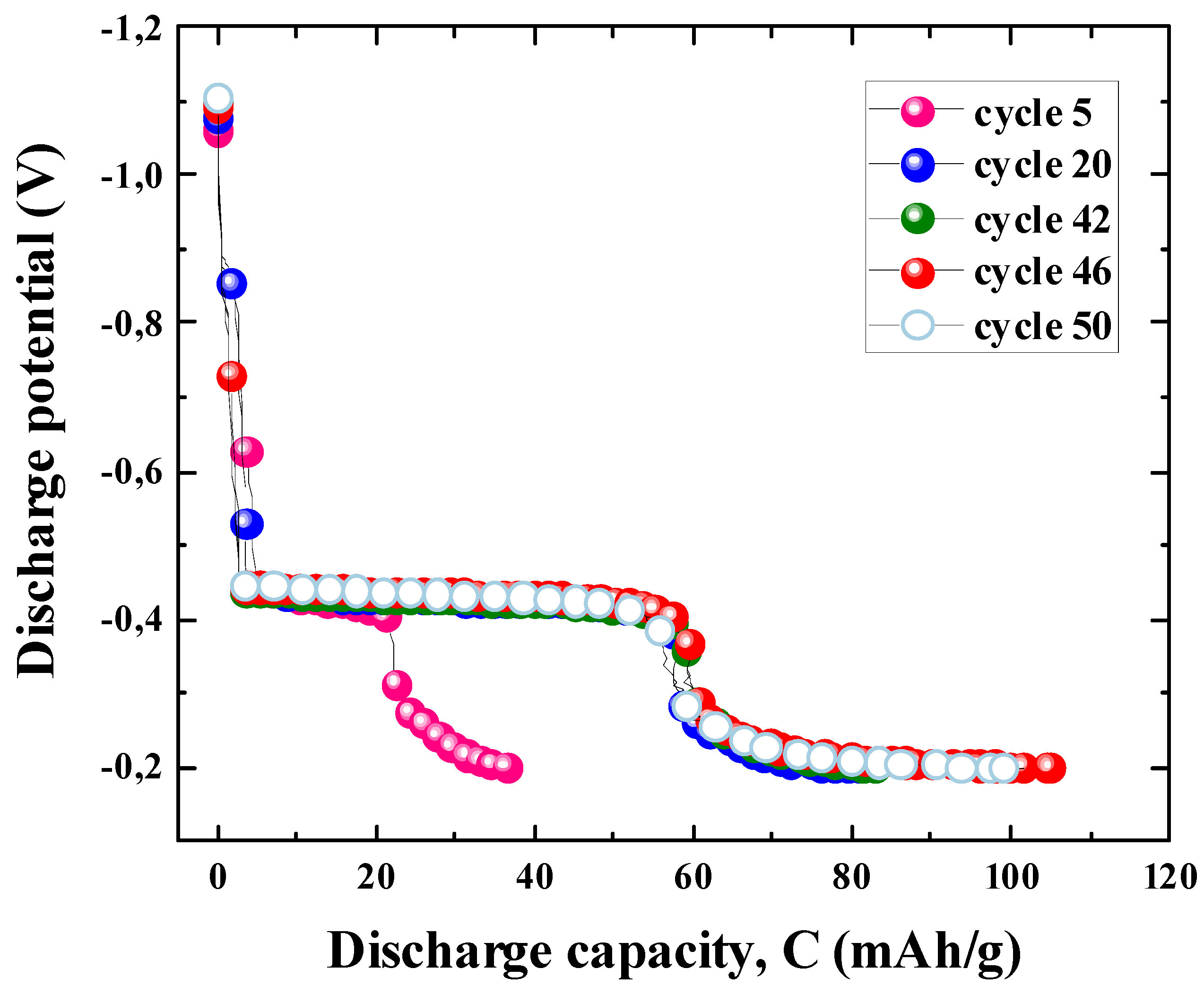
Figure 5.
(A) Half-charge and half-discharge potentials vs number of cycles and (B) Polarization curve for the ZnLaFeO4 electrode determined under a discharge current of 0.8 mA.
Figure 5.
(A) Half-charge and half-discharge potentials vs number of cycles and (B) Polarization curve for the ZnLaFeO4 electrode determined under a discharge current of 0.8 mA.
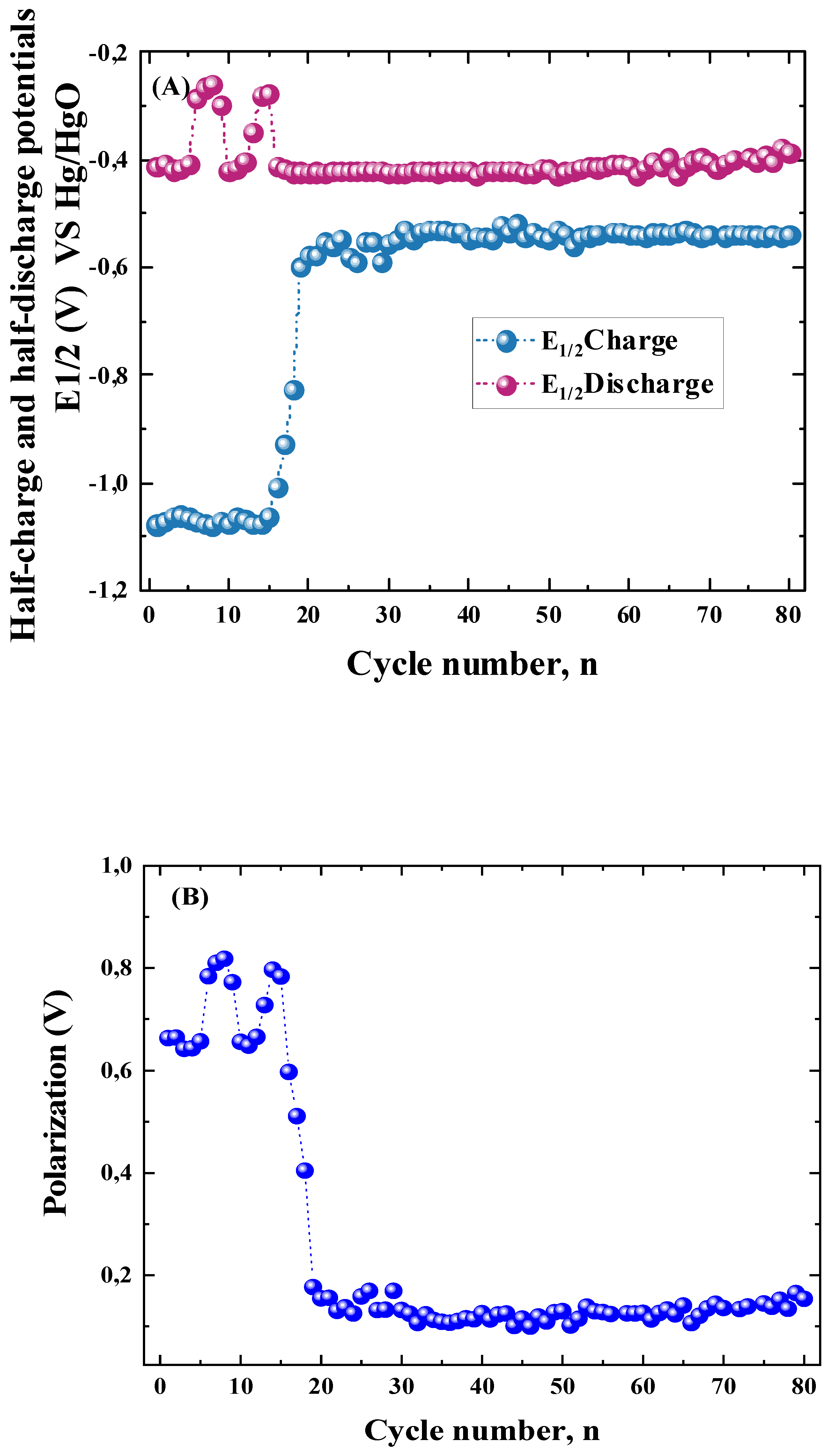
Figure 6.
Evolution of the discharge capacity as a function of the variation of the number of cycles of the ZnLaFeO4 electrode.
Figure 6.
Evolution of the discharge capacity as a function of the variation of the number of cycles of the ZnLaFeO4 electrode.
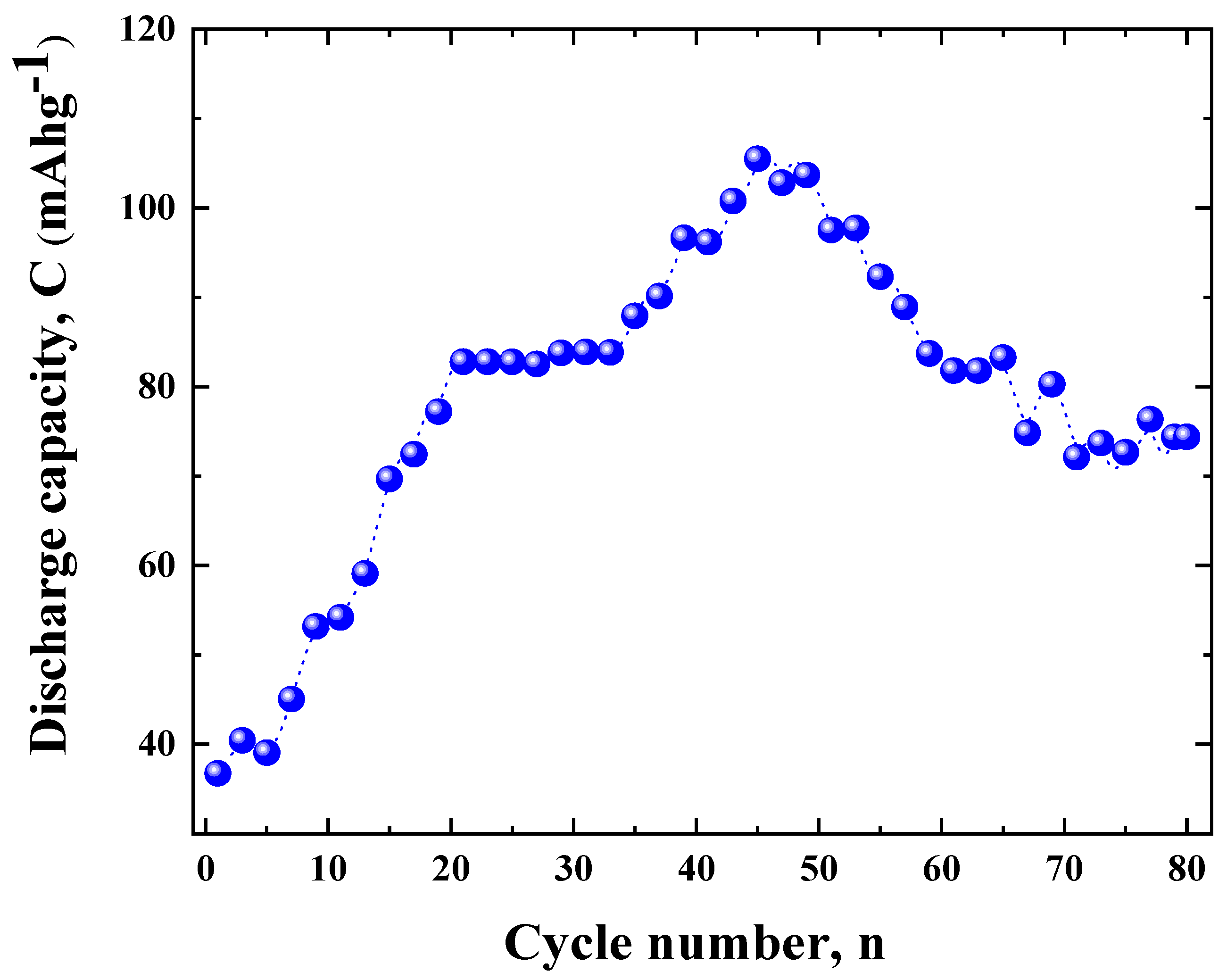
Figure 7.
Figure 7. Capacity fade of the ZnLaFeO4 electrode.
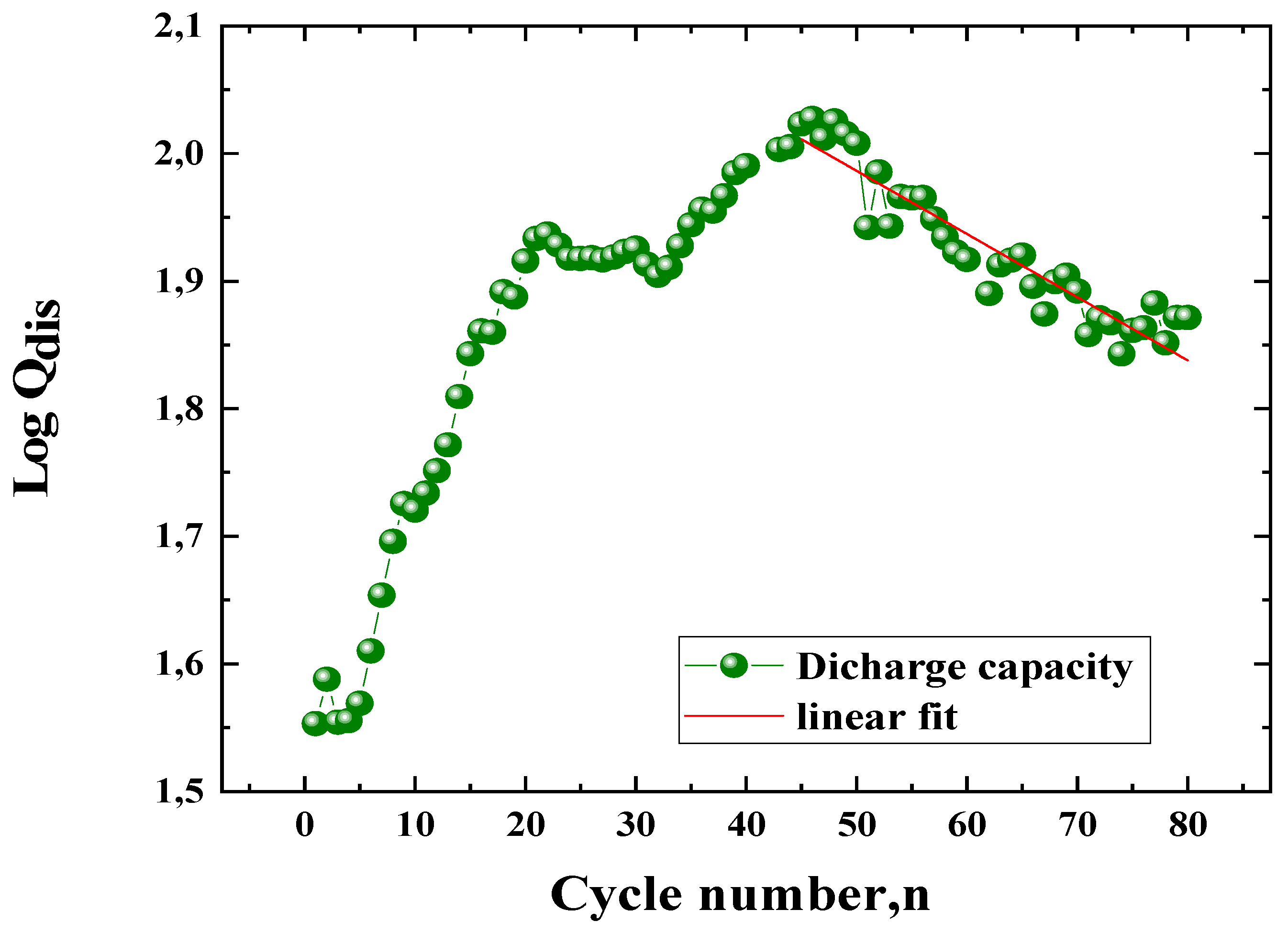
Figure 8.
SEM image of the ZnLaFeO4 (a) and of undoped ZnFe₂O₄ (b) [50] electrode after cycling, electrode after cycling.
Figure 8.
SEM image of the ZnLaFeO4 (a) and of undoped ZnFe₂O₄ (b) [50] electrode after cycling, electrode after cycling.
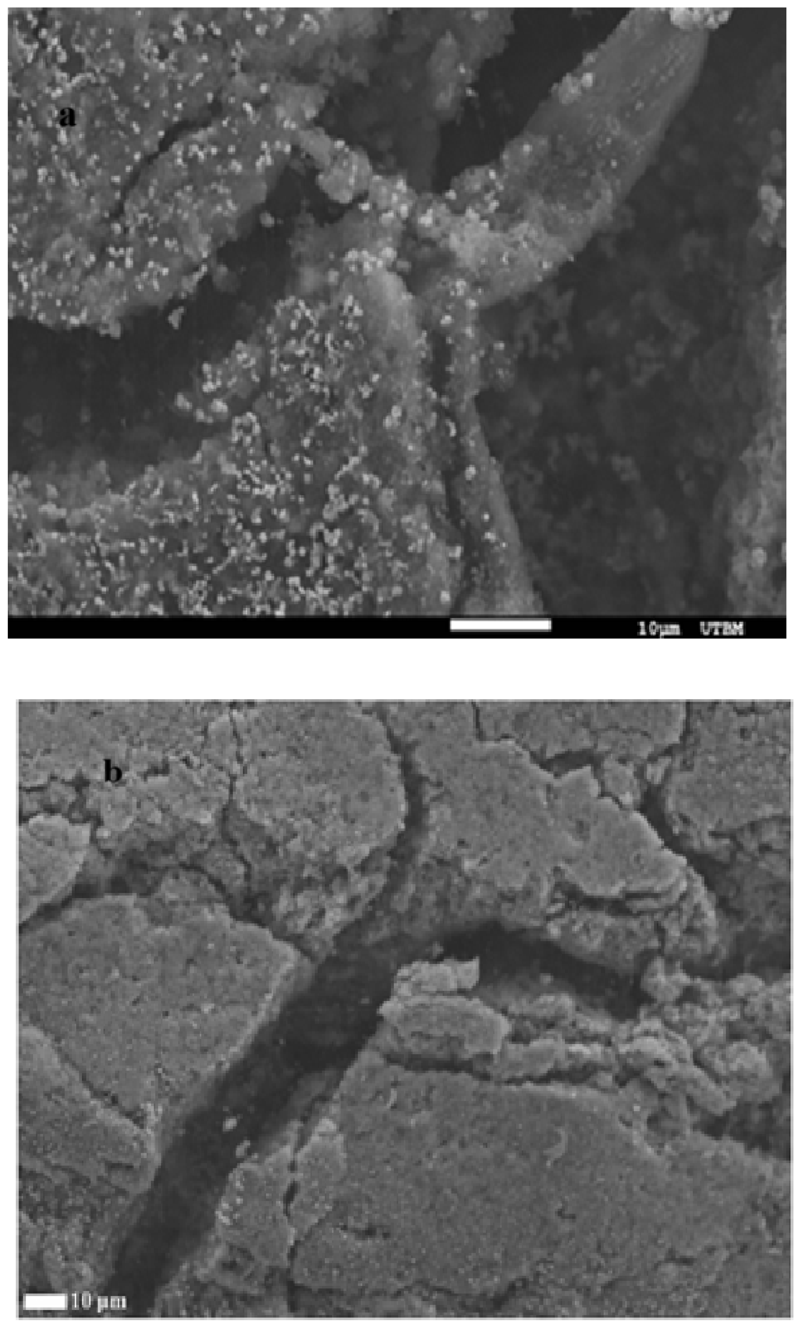
Figure 9.
Evolution of the equilibrium potential of the H2O/H2 system versus cycling, associated to the ZnLaFeO4 negative electrode.
Figure 9.
Evolution of the equilibrium potential of the H2O/H2 system versus cycling, associated to the ZnLaFeO4 negative electrode.
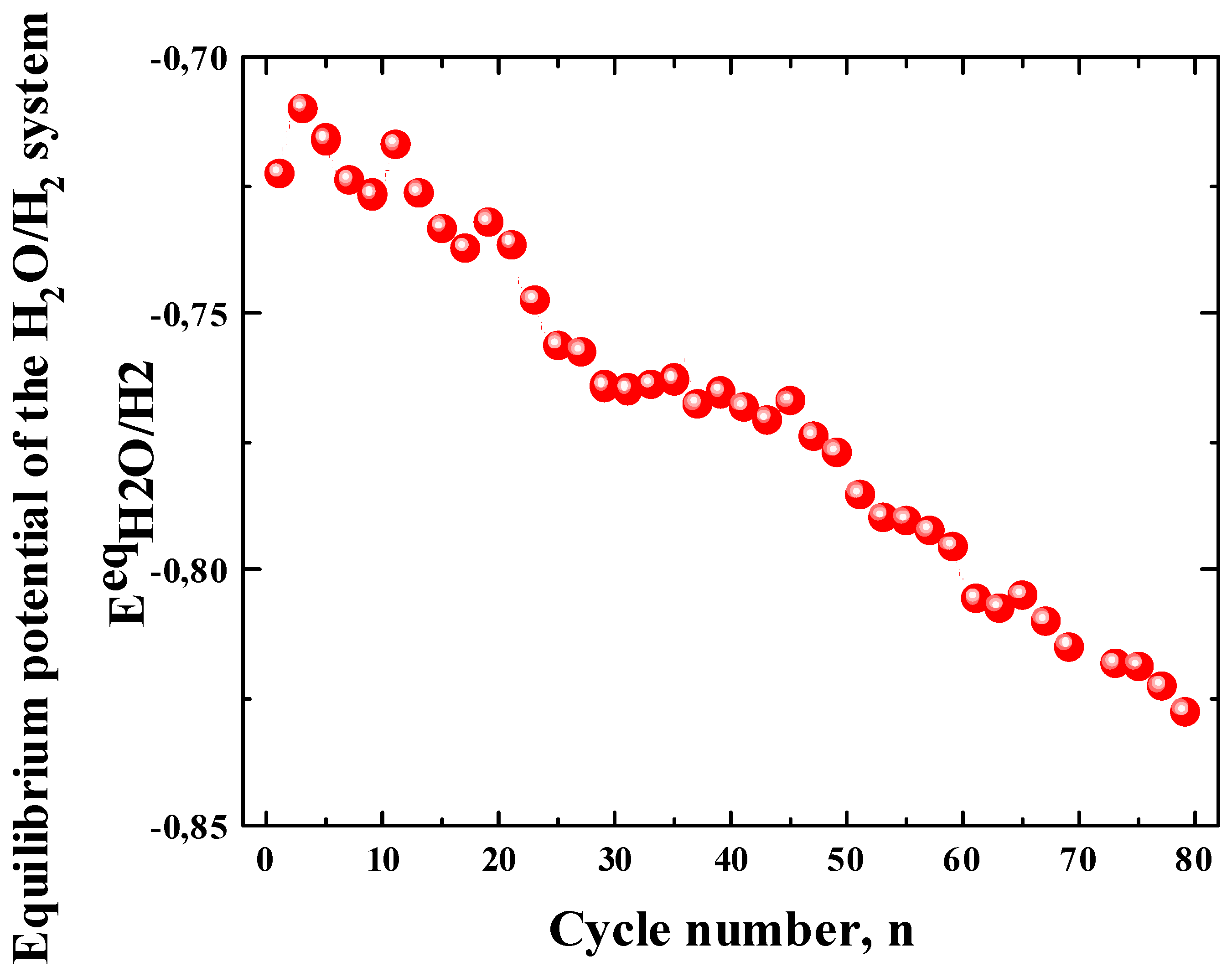
Figure 10.
Theoretical and experimental Tafel curves of the ZnLaFeO4 electrodes during cycling.
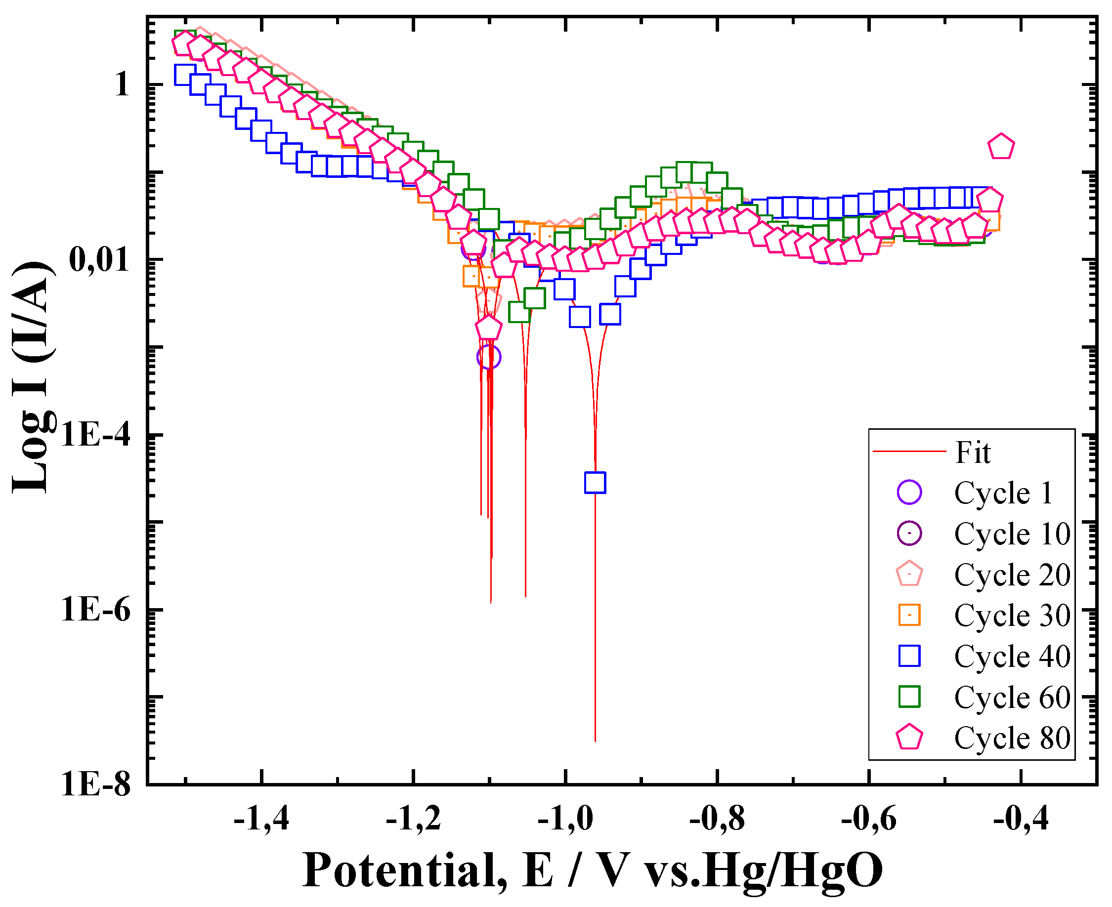
Figure 11.
Evolution of the E0 of the ZnLaFeO4 electrode during cycling .
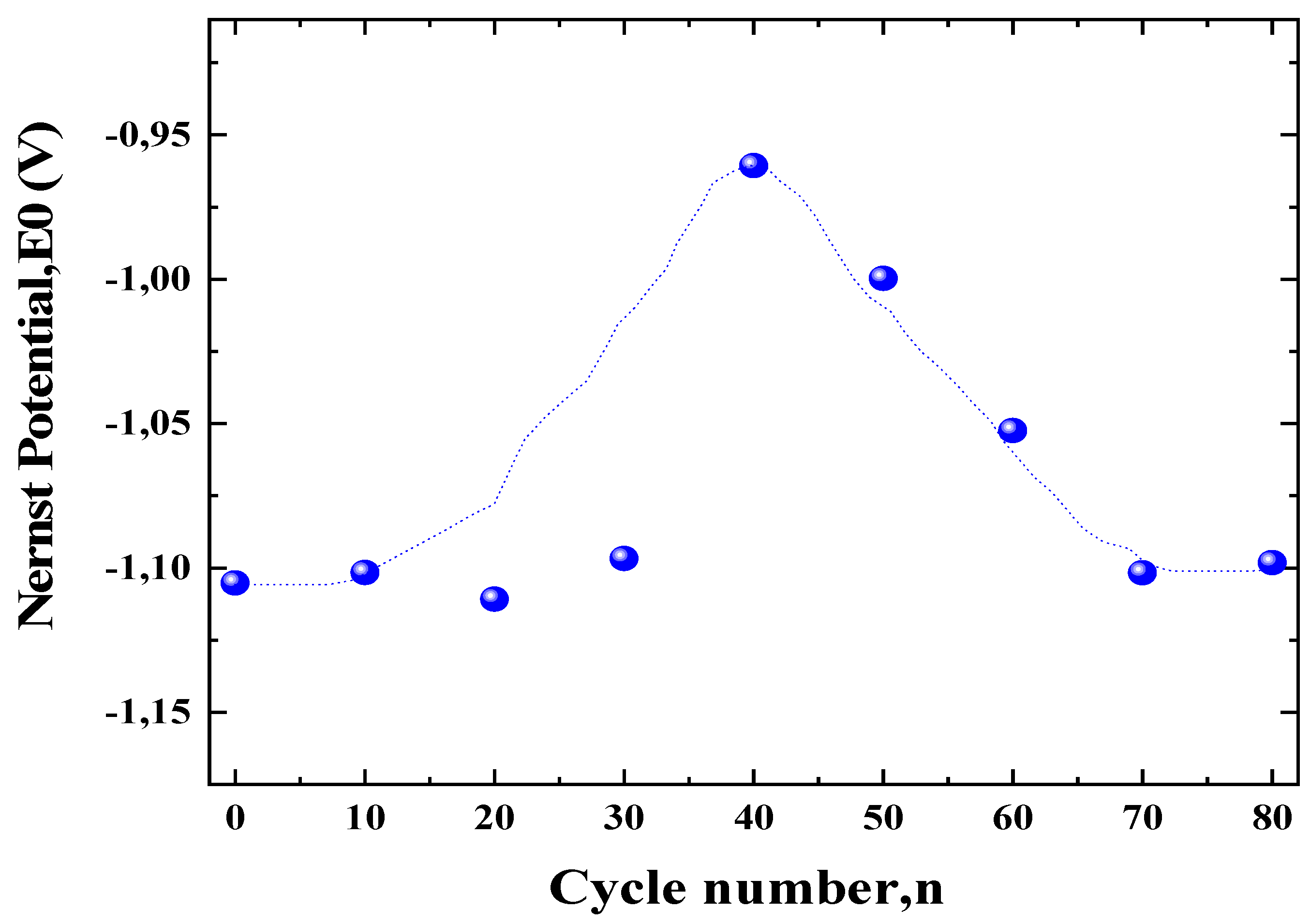
Figure 12.
Change in the exchange current density of the ZnLaFeO4 electrode during cycling.
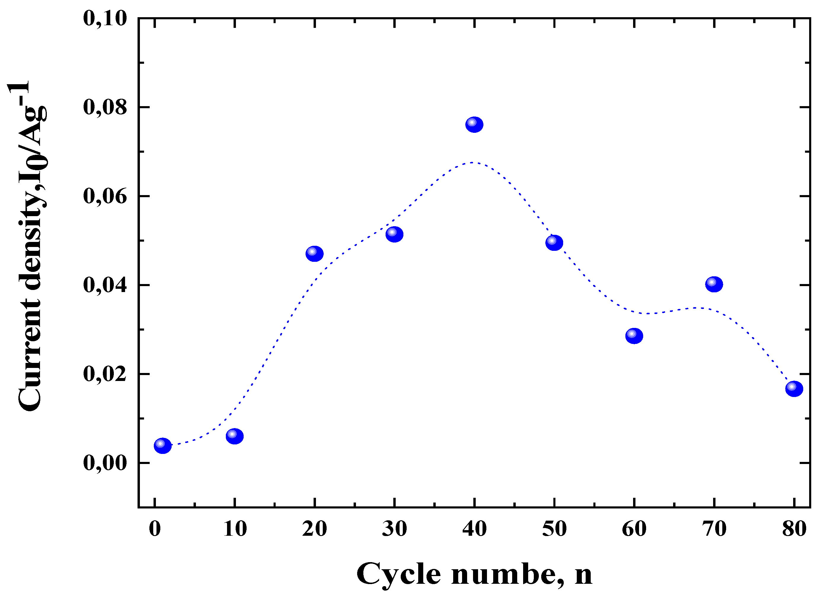

Table 1.
Crystallographic parameters obtained by the Rietveld refinement the powders and the average crystallite size obtained by the two methodes.
Table 1.
Crystallographic parameters obtained by the Rietveld refinement the powders and the average crystallite size obtained by the two methodes.
| Sample | Phases found | Lattice parameters (Å) | Abundance of Phase (wt%) |
Crystallite size Ds(nm) |
Crystallie size DW-H(nm) |
Sig | Fit parameters |
| ZnLaFeO4 | LaFeO3 | a= 5.562 b= 7.841 c= 5.549 |
54.88 | 36.45 |
54.32 |
1.8 |
Rwp = 6.11; Rb = 5.77 Rexp=5.36 |
| La2O3 | a= 3.956 c= 6.137 |
33.23 | |||||
| ZnFe2O4 | a= 8.439 | 11.89 |
Table 2.
Degradation parameters derived from the capacity fade curve.
| Material | Nmax |
Qdisch,max (mAh/g) |
Qdich80 (mAh/g) |
R80 (%) |
K (cycle -1) |
CM (g.cm-3) |
rcorr (g.cm-3.cycle -1 |
|
| ZnLaFeO4 | 46 | 106 | 74 | 69.81 | -0.00495 | 0.01140 | 2.028 | 0.02311 |
Disclaimer/Publisher’s Note: The statements, opinions and data contained in all publications are solely those of the individual author(s) and contributor(s) and not of MDPI and/or the editor(s). MDPI and/or the editor(s) disclaim responsibility for any injury to people or property resulting from any ideas, methods, instructions or products referred to in the content. |
© 2025 by the authors. Licensee MDPI, Basel, Switzerland. This article is an open access article distributed under the terms and conditions of the Creative Commons Attribution (CC BY) license (http://creativecommons.org/licenses/by/4.0/).
Copyright: This open access article is published under a Creative Commons CC BY 4.0 license, which permit the free download, distribution, and reuse, provided that the author and preprint are cited in any reuse.


