
Submitted:
21 January 2026
Posted:
23 January 2026
You are already at the latest version
Abstract
The development of prospective inner and outer space economies focuses on the use of bunch of small space vehicles operated as a quasi-single artificial organism. Such economies include the need for using swarms of small satellites providing communication and surveillance services, being a distributed materials production plant in space, or performing research expedition to study the resources and environments of the new worlds. The use of multiple space vehicles performing tasks as a quasi-single system makes the execution of such missions resilient by reducing the failure risks that is higher for the single-vehicled mission, especially performed in deep space. The core technology for operating distributed space systems is propulsion. From a variety of propulsion technologies ranging from the use of the pressurized cold gas to the implementation of laser beams destroying the surface of solid propellants to generate thrust, some stands out for small spacecraft applications. In this work, the summary on the space-operated propulsion is provided by highlighting the impetus of more frequent use of one technology over other. The discussion on the trends in propulsion is supported by the discussion on the physical, engineering, production, operational, and societal rationales overview. This review serves as the mean for reevaluating of the global propulsion trends and guiding the future inner and outer space propulsion assisting economies effective development.
Keywords:
propulsion system
; electric propulsion
; hall-effect thruster
; ion thruster
; electrospray
; laser propulsion
; pulsed plasma thruster
; electrodeless plasma thruster
; small satellites
1. Introduction
Recent decades have witnessed profound transformations in the aerospace sector driven largely by the proliferation of small satellites [1,2,3,4]. These compact space vehicles, which typically weigh less than 500 kg, have revolutionized various facets of space exploration, including communication, remote sensing, and scientific research. Their affordability [5], adaptability [6], resilience of the systems based on them [7,8], and swift deployment capabilities [9,10] have positioned them as essential tools for governments, corporations, and research entities [11].
Concurrently, the evolution of small satellites has intensified scrutiny on their propulsion systems [12,13,14]. Propulsion plays a pivotal role in ensuring that the satellites achieve and maintain their designated orbits, execute intricate maneuvers, and fulfill mission objectives efficiently [15,16,17]. Selecting the right propulsion technology for small satellites is a multifaceted endeavor demanding thorough consideration of factors such as mission duration, orbital requirements, and maneuvering demands [18,19].
To meet the growing needs of establishing, development, and prosperity of space economies, it is imperative to develop proliferated space systems that heavily depend on robust propulsion systems [20,21,22]. These systems not only enable precise orbit maintenance but also allow for complex maneuvers necessary for different applications [23]. Furthermore, these propulsion systems should possess thrust vector control capability, enabling precise adjustment of direction and magnitude of thrust [24]. This feature enhances the overall performance and reliability of small satellites, ensuring they can effectively carry out their intended functions [25].
This paper systematically reviews the trends and prospects of propulsion technologies for small satellites. Beginning with an examination of the classification of space missions and highlighting the importance of propulsion for modern small satellite missions, the discussion is proceeded to the flight-operated propulsion systems, its merits and limitations, and its implications for small satellite operations. Then, both experimental evidences and theoretical insights are emphasized, focusing on critical factors related to several rationales—physics, engineering, production, operational, and societal—and provide a structured evaluation framework to reveal directions for prospective propulsion technologies for small satellites for future research and development efforts. This review serves as the mean for reevaluating of the global propulsion trends and guiding the future inner and outer space propulsion assisting economies effective development.
The Section 2 presents the classification of space missions based on small satellites making emphasis on that the propulsion technologies become the most critical component of these missions. In the Section 3, different propulsion technologies that have been operated onboard small satellites in space are discussed. The Section 4 presents the discussion on the different types of rationales on the development, studying, and operations and the trends and the perspectives in the field of small satellites propulsion systems.
2. Space Missions of Small Satellites
Visual representation through Figure 1 portrays the expanded classification of space missions based on small satellites. Five main class-types have been selected to construct the general classification, namely, orbital assignment, grouping type, duration, purpose, and propulsion.
The orbital assignment is important parameter that affects the mission’s objectives and requirements. There are various orbit types, namely, highly elliptical orbit (HEO), geostationary orbit (GEO), low Earth orbit (LEO), medium Earth orbit (MEO), or interplanetary assignment, including orbiting around other space objects. It should be noted that the assignment of small satellites can be beneficial for proliferated resilient systems [26]. Each orbit type has its own set of challenges and benefits, such as the need for different propulsion systems and the ability to observe different parts of the Earth.
The grouping type refers to the number of satellites involved in the mission. The Figure 1 categorizes missions based on the number of spacecraft, ranging from single spacecraft to megaconstellations. The mission’s categorization based on its duration includes ranges from short-term missions lasting less than 3 months to long-term missions lasting more than 3 years. This classification helps in understanding the time commitment required for different types of missions and the resources needed to sustain them. The purpose of space missions based on small satellites are encompass a multitude of domains, including communication, remote sensing of natural space objects, environmental monitoring, space situational awareness, materials production, and scientific applications. Appreciating the diversity of these missions proves invaluable in identifying suitable propulsion technologies that cater precisely to mission-specific demands.
The use and type of propulsion system are crucial for determining the capabilities and limitations of any space mission. The Figure 1 classifies missions based on the type of propulsion used, maneuvering capability, thrust levels, dynamic of operation, assignment type, and precision. This information is essential for understanding the energy requirements and the maneuverability of the spacecraft, the parameters that are especially important for modern and prospective small satellites missions. The precision capability of the propulsion system is determined by the accuracy of the thrusters to generate distinct acting impulses and forces on a satellite. The maneuvering capability of the spacecraft is another important factor that determines the mission’s flexibility and adaptability and depends on the propulsion system capabilities to generate propulsive forces of different levels and durations and to control thrust vector direction.
Propulsion systems are crucial in ensuring that small satellites not only reach but also maintain their intended orbits, carry out elaborate maneuvers, and fulfill mission objectives with utmost efficiency. Specifically, orbit injection entails accelerating satellites into targeted orbits immediately post-launch. Station-keeping addresses minor deviations, preserving consistent positions. Debris avoidance enables circumvention of space debris or potential collision events. Inter-satellite coordination synchronizes collaborative activities among satellites arranged in formations. Finally, end-of-life deorbiting guarantees safe removal of satellites from orbit once missions come to completion. Acknowledgment of these functional responsibilities enhances the ability to select propulsion technologies that optimize mission outcomes while simultaneously curbing expenditures and operational risks.
3. Space-Operated Small Satellites Propulsion Technologies
3.1. Chemical Propulsion
There are three main types of chemical propulsion—the monopropellant rocket (see Figure 2), the bi-propellant rocket (see Figure 3), and the hybrid rocket (see Figure 4) engines.
The operation of chemical propulsion depends on the type of the propellant being used. For single-component propellant engines (monopropellant rocket engines), thrust is generated through thermal decomposition. In this case, the propellant comes into contact with a catalyst inside the combustion chamber, leading to chemical breakdown, heat release, and formation of high-temperature gases. Under high pressure, these gases exhaust through the nozzle, generating thrust [27,28]. In two-component systems (bi-propellant rocket engines), it is required to use fuel and oxidizer, stored onboard either in liquid or gaseous forms. These components mix in a specified ratio and ignite spontaneously when brought together or require external ignition devices. Combustion produces hot gas, which, under high pressure, exhaust through the nozzle, generating thrust [27,28]. Chemical engines also encompass systems that utilize propellants in different states (hybrid rocket engines) [29].
Table 1 presents the flight-operated chemical propulsion units suitable for small satellites. All mentioned engines typically have analogous versions within the same series but with increased size, thrust, and power output.
In 2014, a single-component propulsion unit fueled by concentrated hydrogen peroxide was launched aboard Hodoyoshi-3. Though this satellite wasn’t a CubeSat and weighed 56 kg inclusive of propulsion system fuel, operational details concerning the propulsion unit remain unavailable to authors of this study.
Onboard the 3U CubSsat LituanicaSAT-2 was a mono-propulsive EPSS C1K unit, using ammonium dinitramide as its propellant. Mission data from Kongsberg NanoAvionics indicates that this unit imparted a speed increment (∆V) of 10 cm/s to the satellite, significantly affecting its orbital parameters.
Aerospace Corporation developed a steam-based propulsion unit. While there are no chemical reactions involving the propellant here, these types of engines still classify as chemical. Water is stored in liquid form on board, converted to steam by heating, and expelled through the nozzle to create thrust. Flight trials of this propulsion unit were conducted on 1.5U AeroCube-7 (2017) and AeroCube-10 (2019) CubeSats. The mission aimed to showcase the potential of this unit, for instance, bringing two AeroCube-10 satellites close enough to each other (~50 meters apart) [30,31].
AAC CLUSE SPACE collaborated with Dawn Aerospace to develop the bi-propellant rocket engine PM200, driven by nitrous oxide and propylene. PM200 was deployed on the 6U CubeSat Hiber in 2021. However, reports suggest that two out of four satellites in the Hiber constellation ceased functioning. Two others experienced irreparable technical problems, and no detailed flight trial data exists for the propulsion unit; only ground test data is available.
HYDROS-C propulsion unit was integrated into the 6U CubeSat PTD-1, placed into a sun-synchronous orbit in January 2021. Within the Pathfinder Technology Demonstrator project, HYDROS-C occupies 2U of volume and serves as payload. The satellite contains a water reservoir, where water is electrolytically split into gaseous hydrogen and oxygen. These gases are mixed and subjected to standard combustion processes typical of two-component liquid rockets. Hot gas is expelled under pressure through the nozzle, generating thrust. During flight trials, the propulsion unit yielded satisfactory outcomes: specific impulse ranged from 223 to 241 seconds, and total impulse fluctuated between 3.12 and 3.38 N·s [32].
In 2021, the LFPS propulsion unit, jointly developed by Plasma Processes and NASA Marshall, was installed on the CubeSat Lunar Flashlight. Designed to explore ice deposits on the Moon’s south pole, the unit featured four nozzles [33]. However, during operation, it was observed that the engines failed to deliver sufficient thrust. Several troubleshooting efforts were attempted, yet the satellite never reached lunar orbit. Possible causes might involve unwanted particulates in the fuel feed system [34].
CAPSTONE (Cislunar Autonomous Positioning System Technology Operations and Navigation Experiment) is a 12U-CubeSat-class spacecraft launched by NASA on June 28, 2022. The mission aimed to validate autonomous navigation technology and investigate near-straight halo-orbits around the Moon, envisioned as a foundation for future lunar gateways. Integrated HIPS (Hybrid Interim Propulsion System), consisting of eight mono-reactive engines, enabled orbital corrections and attitude adjustments. Despite challenges encountered during operation, CAPSTONE successfully entered halo-orbit on November 13, 2022, continuing to provide valuable insights for the Artemis program. This mission underscores the efficacy of autonomous navigation and the feasibility of small-scale spacecraft in deep-space environments.
Dawn Aerospace supplies qualified flight engines and comprehensive CubeDrive propulsion systems sized from 0.8 to 2U, offering cumulative impulses from 402 N·s to 1450 N·s, respectively. Per company records, CubeDrive has been utilized on several spacecraft, notably the 16U CubeSat SC1 (GITAI), launched in 2024. However, updated data regarding CubeDrive’s performance and specifications remains undisclosed.
The Aerospace Corporation developed the HyPer propulsion unit, powered by hydrogen peroxide. Installed on the 12U CubeSat Slingshot-1, launched in 2022, the propulsion unit didn’t perform any maneuvers requiring changes in characteristic velocity (∆V); instead, it acted as payload to demonstrate the technological viability of such units. HyPer was designed to evaluate its operability under diverse conditions, including temperature variations, thrust levels, duty cycles, and burn durations. Furthermore, the aim was to assess how effectively HyPer would operate with a completely filled fuel tank. Post-experiment analysis revealed that HyPer successfully functioned throughout extensive orbital campaigns comprising 34 experiments conducted at elevated temperatures. During each experiment, the valve condition, temperature, and pressure were monitored, enabling detailed orbital analyses to determine the resulting change in characteristic velocity (∆V). Final assessments indicated that HyPer delivered a ∆V value of 21.5 mm for a 19 kg spacecraft [35,36].

Table 1.
Flight-operated chemical rocket engines.
| PS | Entity | Propellant | P, W | T, N | Isp, s | It, kN·s | Size | Mass, kg | Missions (Year) | NORAD ID | Ref. |
|---|---|---|---|---|---|---|---|---|---|---|---|
| MPSØ | UTokyo | H2O2 | - | 0.5 | <80 | - | - | - | Hodoyoshi-1/Hodoyoshi-3 (2014) | 40299/40015 | [37] |
| EPSS C1K● | NanoAvionics | ADN | 7.5 | <0.3 | 214 | 0.4 | 1.3U | 1* | Lituanica-2 (2017) | 42768 | [38] |
| Steam Propulsion▲ | The Aerospace Corp. | H2O | 12 | 0.004 | 70 | - | <1U | - | Aerocube 7 (2017), Aerocube 10 (2019) | 40966, 44485 | [30] |
| PM200● | Dawn Aerospace | N2O+C3H6 | 12 | 0.5 | 285 | 0.85 | 1U | 1.1* 1.4** |
Hiber-4 (2021) | 47541 | [39] |
| HYDROS-C▲ | Tethers Unlimited | H2O | <25 | >1.2 | <241 | <3.38 | 2U | 2.7** | PTD-1 (2021) | 47482 | [32,40] |
| LFPS▲ | NASA MSFC | ASCENT | <47 | 0.1 | <200 | <3.5 | 2.4U | 5.5** | Lunar Flashlight (2022) | 54697 | [33,34,40] |
| Monopropellant CubeSat System● | Stellar Exploration | Hydroxyzine | - | 0.25 | 200 | - | - | - | NASA Capstone (2022) | 52914 | [41] |
| ArgoMoon Hybrid MiPSX | ECAPS | LMP-103S | 20 | 100 | 190 | 0.783 | 1.3U | 1.43* 2.07** |
ArgoMoon (2022) | 55907 | [42] |
| HyPer▲ | The Aerospace Corp. | H2O4 | - | - | <124 | - | 0.25U | - | Slingshot-1 (2022) | 52947 | [39] |
| HAN-based propulsion unitØ | Hunan Hangsheng Satellite Technology | HAN | - | - | - | - | - | - | Jinta (2023) | 56169 | [43] |
| CubeDrive 0.8U● | Dawn Aerospace | N2O+C3H6 | 15 | 0.49…1.35 | <248 | 0.4 | 0.8U | 1.051* 1.250** |
SC1 (2024) | 62388 | [44] |
| * Dry mass. ** Wet mass. ▲ PS distinct operating parameters of which are available in open information sources. ● PS demonstrated in orbital flights, but data on its characteristics varies in different sources. Ø PS demonstrated in orbital flights, but there are no open data on its characteristics. X Propulsion systems that have been launched into space but have failed to successfully demonstrate its functionality in orbital conditions for various reasons. | |||||||||||
3.2. Cold Gas
Cold gas thrusters are among the simplest and most reliable in operation. They are widely used in space systems for orientation and stabilization, orbit correction, and other purposes. Additionally, they serve as vernier thrusters on launch vehicles. For example, on the Pegasus launch vehicle, they were used to adjust pitch angle, while on the reusable first stage of the Falcon 9 rocket, they ensured stability before landing back on Earth [45].
The operational principle of these thrusters is based on utilizing compressed gas energy. The principal scheme of the cold gas thruster is presented in the Figure 5. In its simplest configuration, high-pressure gas is stored in a tank. When commanded to open the valve between the fuel tank and nozzle, the gas flows through a filter designed to remove foreign particles and enters the nozzle. The gas exhausts through the nozzle generating the reactive thrust [45].
More complex systems include two tanks: one with liquid propellant and another intermediate tank that maintains part of the propellant in gaseous form. The propellant exhausts through the nozzle having the hydraulic connection line with the tank in which the propellant is in the gaseous state. Then, this tank is refiled with the propellant stored in the tank in which it is in the liquid form [45]. Typically, the gas exiting the nozzle does not heat up, hence this type of thruster is called “cold.” However, there are systems using “warm” gas. These systems have heaters installed, increasing the specific impulse of the thruster [45]. Currently, many models of the cold gas thrusters have been operated in space. The flight-operated cold gas thrusters are presented in the Table 2.
SNAP-1 is a nanosatellite launched in 2000. It was equipped with a pencil-sized cold gas thruster utilizing butane as a propellant. This unit provided an approximate change in characteristic velocity of about 2 m/s. The cold gas thruster used onboard SNAP-1 successfully demonstrated position control and orbital maneuvers, raising its semi-axis by more than 3 km and capturing images of nearby satellites, achieving a measured specific impulse of approximately 43 seconds [46].
As part of the STS-116 mission, two picosatellites named MEPSI, measuring 101 x 101 x 127 cm3 each and weighing 1.4 kg, were deployed. One satellite had an identical propulsion system whose task was to replicate the maneuvers of the second satellite without a propulsion system. Based on the amount of consumed propellant (0.2 cm³) at a pressure of 793 kPa, the total impulse of the performed maneuver was calculated to be 2.6 mN·s, with a specific impulse of 30 seconds [47].
T3 µPS is a cold gas thruster developed for the Delfi-n3Xt 3U format satellite. The propellant used was nitrogen, stored aboard in solid state as granules. To convert nitrogen into gas, a heater is employed, followed by pressurized delivery to a reservoir where it can be directed toward the nozzle upon command [48].
CNAPS cold gas thruster, equipped with four nozzles, was integrated into the CanX-4 and CanX-5 satellites launched in 2014. Weighing 15 kg, these cubic-shaped satellites measure 20 cm per side. Their primary objective was to demonstrate group flight using propulsion systems. The propulsion unit could generate thrust ranging from 12.5 to 50 mN depending on the tank pressure and number of active thrusters. Thanks to the placement of four nozzles on one side of the satellite relative to its center of mass, the moment management system operates automatically, selecting the set of thrusters required to compensate accumulated momentum. The sulfur hexafluoride was utilized as the propellant due to its high density and low saturated vapor pressure, ensuring self-sealing properties. These characteristics make SF6 inert and non-toxic, providing safety and compatibility with most materials [49].
POPSAT-HIP1 thruster was integrated into a similarly named 3U-sized CubeSat. The thruster head, power supply, and control system occupied 1U volume. The tanks containing argon utilized as the propellant took up 1U. Estimated full change of the characteristic velocity during the mission reached 3 m/s, with thrust varying within the range from 0.1...0.3 mN, and overall total impulse dependent on conducted experiment from 2 to 16 mN·s. On this satellite, the main payload was the propulsion system [50].
NanoProp CGP3 and NanoProp 6U are propulsion systems was used on the TW-1 (3U format) and GOMX-4B (6U format) CubeSats, respectively. Both systems use butane as the propellant and microelectromechanical technologies (MEMS) [40]. Microelectromechanical systems (MEMS) represent integrated technologies incorporating miniature mechanical and electromechanical components fabricated using microfabrication techniques. Dimensions range from fractions of micrometers to several millimeters. MEMS designs may vary from simple configurations lacking moving parts to complex ones including multiple movable elements controlled by microelectronic components. A key feature of MEMS is the presence of at least one element with mechanical functionality.
In the context of the LONESTAR program, a 3U CubeSat Bevo-2 was operated, carrying a cold gas thruster developed by Georgia Tech SSDL. Although brief contact with Bevo-2 was established, the intended propulsion goals were not achieved [51].
NASA C-POD MiPS cold gas thruster consists of two identical propulsion units, each equipped with eight nozzles. They were integrated into 3U CubeSats CPOD-A and CPOD-B. The primary goal of these satellites was to test scenarios involving rendezvous, maneuvering, and docking operations. Despite successful functioning of the propulsion units, certain tasks were incomplete due to outdated equipment at the time of launch and issues related to receiver leakage [52].
A 3U CubeSat Ursa Maior’s propulsion unit employs MEMS technology. The MEMS nozzle has axisymmetric geometry and is controlled by a MEMS valve primarily acting like an electromagnetic valve [53].
MarCO MiPs propulsion units, manufactured by VACCO, were installed on two 6U-class spacecraft—MarCO A and MarCO B. The mission of these satellites involved exploring Mars and accompanying the Insight lander module. MarCO became the first nanosatellites to function beyond Earth’s orbit. Despite discovering a fuel leak in the MarCO propulsion unit en route to Mars, this did not affect the success of the mission. Each propulsion unit contained eight nozzles capable of generating 25 mN of thrust each [39].
Table 2.
Flight-operated cold gas thrusters.
| PS | Entity | Propellant | P, W | T, mN | Isp, s | It, N·s | Size | Mass, kg | Missions (Year) | NORAD ID | Ref. |
|---|---|---|---|---|---|---|---|---|---|---|---|
| SNAP-1▲ | SSTL | C4H10 | 15 | 46 | 43 | - | <1U | 0.5 | SNAP-1 (2000) | 26386 | [54] |
| MEPSI▲ | The Aerospace Corporation | Xe | - | 100 | 30 | - | ~1U | 0.188 | STS-11 (2002), STS-11 (2006) | 27556, 29647 | [47,55] |
| T3 µPS▲ | TU Delfi | N2 | 10 | 6 | >30 | - | 0.25U | 0,.2 | Delfi-n3Xt (2013) | 39428 | [39,55] |
| CNAPS▲ | UTIAS | SF6 | 3 | 12.5…50 | 45 | 100 | 2U | 0.26 | CanX-4/CanX-5 (2014) | 40056, 40055 | [39,49,55] |
| POPSAT-HIP1▲ | Microspace Rapid | Ar | 2 | 0.1…0.3 | 32 | 0.6 | 1U | - | POPSAT-HIP1 (2014) | 40028 | [50] |
| NanoProp● CGP3 | GomSpace | C4H10 | 2 | 1 | 60…110 | 40 | 0.5U | 0.35** | TW-1 (2015), Astrocast-0301 (2021), Astrocast-0205 (2022), ESTCube-2 (2023) | 40928, 54370, 48960 | [40,56] |
| Bevo-2 Cold Gas PSX | Georgia Tech SSDL | R236fa | - | 110…150 | 65…89 | 58…80 | - | 0.31* 0.4** |
Bevo-2 (2015) | 41314 | [51] |
| NASA C-POD MiPS● | VACCO | R236fa | 5 | 10 | 40 | 174 | 0.8U | 1.3** | NanoACE (2017), CPOD A/B (2022) | 42844 | [57] |
| MEMS Cold Gas MicroThruster● | CRAS | GN2 | <1 | 1 | - | - | 0.5U | 0.118* | Ursa Maior (2017) | 42776 | [58] |
| MarCO MiPS● | VACCO | R236fa | 0.5 | 25 | 42 | 755 | 2,5U | 3.49** | MarCO-A/MarCO-B (2018) | 43596/43597 | [57] |
| NanoProp● 6U | GomSpace | C4H10 | 2 | 1 | 60…110 | 80 | 200× 100× 50mm3 | 0.9** | GOMX-4B (2018) | 43196 | [59] |
| I2T5● | ThrustMe | I2 | 5 | <0.35 | - | 75 | 0.5U | 0.9** | Xiaoxiang 1-08 (2019), NAPA-2 (2021), Robusta-3A (2024) | 44706, 48963, 60243 | [40] |
| Cold Gas Thruster● | UT Austin | R236-fa | - | 110…170 | 65…100 | - | <1U | - | Armadillo (2019) | 44352 | [60] |
| Seeker Robotic Free Flyer Propulsion SystemØ |
NASA | GN2 | - | 100 | - | - | 1.25U | - | Seeker (2019) | 44533 | [61] |
| NEA Scout Propulsion System● | VACCO | R236fa | <55 | 25 | 40 | 500 | 2U | 1.26* 2.5** |
LiciaCube (2021) | - | [39,40] |
| ASCENT Cold Gas PSØ | Georgia Tech SSDL | - | - | - | - | - | - | - | ASCENT (2021) | 51287 | [51] |
| Tianyuan Cold Gas ThrusterØ | Nanjing University of Science and Technology | - | - | - | - | - | - | - | Tianyuan-1 (2021) | 49315 | [62] |
| GDU● | EDB Fakel | N2 | 9 | 51.9…96.5 | 70…120 | 163× 95×95mm3 | 1.1 | Geoskan Edelweis (2022) | 53385 | [63] | |
| ArgoMoon MiPSX | VACCO | R134a | Разoгрев 20 Рабoта 4,3 |
25 | - | 72 | 1.3U | 1.43* 2.07** |
ArgoMoon (2022) | 55907 | [64] |
| BioSentinel Propulsion System● | Georgia Tech SSDL | R236fa | 4 | 40…70 | 41…47 | 79.8 | 2U | 1.28** | BioSentinel (2022) | 55906 | [40,65] |
| OMOTENASHI propulsion systemX | VACCO | R236fa | - | 25 | - | 584 | 1.7U | 1.62* | OMOTENASHI (2022) | 99345 | [66] |
| Hamlet▲ | NASA Ames | R236fa | - | 2…12 | 42 | - | 2U | 1.47* 2.45** |
Starling 6U (2023) | 57388 | [67] |
| Politekh Univers-3 Ø | St. Petersburg Polytechnic University | R11 | - | - | - | - | - | - | Politekh Univers-3 (2023) | 57191 | [68] |
| Cold Gas Propulsion SystemØ | GomSpace | - | - | - | - | - | 2U | - | Juventas (2024) | - | [69] |
| * Dry mass. ** Wet mass. ▲ PS distinct operating parameters of which are available in open information sources. ● PS demonstrated in orbital flights, but data on its characteristics varies in different sources. Ø PS demonstrated in orbital flights, but there are no open data on its characteristics. X Propulsion systems that have been launched into space but have failed to successfully demonstrate its functionality in orbital conditions for various reasons. | |||||||||||
I2T2, the first compressed-gas propulsion unit using iodine as the propellant, successfully passed flight tests. It was integrated into 6U-sized XiaoXiang 1-08 CubeSat and marked history as the first cold gas thruster where iodine served as a propellant in outer space [70].
The concept behind the propulsion unit installed on the 3U CubeSat Armadillo involves employing stereolithography methods for additional manufacturing of the main drive module. This approach allows synthesizing complex elements and implementing geometric forms of significant complexity [60].
The cold gas thruster onboard LiciaCube was operated successfully. This satellite was part of the DART mission aimed at testing asteroid Dimorphos’ trajectory alteration capabilities. LiciaCube photographed the effects of DART on the asteroid [71].
DFAST, an autonomous propulsion unit developed for swarm flying CubeSat, is currently untested since the 3U CubeSat BSS-1 was placed into orbit but failed to establish communication.
Successfully tested on the Geoskanner-Edelweis CubeSat, weighing 2.909 kg, the GDU cold gas thruster uses nitrogen as its propellant. Equipped with a heater to increase specific impulse, which varies from 70 to 120 seconds depending on heater performance, the maximum engine power consumption reaches 9 W, with storage pressure reaching 39.2 MPa [63].
ArgoMoon Hybrid MiPS, a hybrid propulsion unit developed by VACCO, was integrated into the 6U-sized ArgoMoon satellite. The primary purpose of this satellite was photographing the second stage of the SLS launch vehicle. Due to substantial rotation following deployment, the mission objectives were not fully met, leaving information regarding the functional status of the propulsion unit unknown. The ArgoMoon Hybrid MiPS propulsion unit consisted of four nozzles through which refrigerant R236fa flowed, along with a single liquid-fueled rocket engine (LRE) running on green monopropellant LMP-103S [64].
BioSentinel’s propulsion unit, developed by Lightsey Space Research, was integrated into the eponymous 6U-sized BioSentinel CubeSat. The mission of this satellite focused on studying the impact of cosmic radiation on living organisms. For BioSentinel, the propulsion unit played a critical role, maintaining constant satellite orientation so that solar panels remained aligned towards the Sun, essential for fulfilling the mission requirements of BioSentinel [72].
The 6U-sized OMOTENASHI satellite carried a cold gas thrusters produced by VACCO. After deployment, it was discovered that the satellite was misaligned with respect to the Sun, preventing electricity generation. Following several attempts to reconnect with the satellite, the team decided to terminate the mission. Reports indicate a leak of gas from the propellant tanks of the gas propulsion unit [73].
Hamlet thruster was used for correcting orbits of 6U satellites in the Starling constellation. It is reported that the operation of the propulsion unit was onboard four satellites: SV-1, SV-2, SV-3, and SV-4 [67]. Fuel leak occurred on SV-1, causing deviation from planned mission objectives. Other satellites in the group moved closer to SV-1 to conduct scheduled experiments. Different values of ∆V were transferred to each satellite, ranging from 0.96 to 5.44 m/s. Spent propellant masses varied accordingly, from 29 to 170 grams. Total impulse ranges from 2 to 12 mN/nozzle and depended on the propellant tank pressures [67].
3.3. Electric Propulsion
3.3.1. Electrostatic EP
In the electrostatic type electric propulsion, the energy supplied to the thruster is first used for ionizing the propellant, after which ions are accelerated by an electric field [74]. Electrostatic type electric propulsion includes Hall-effect (see Figure 6 and Figure 7), ion (see Figure 8 and Figure 9), and electrosprays (see Figure 10) thrusters. Such type of propulsion often requires a cathode-neutralizer that compensates for the positive charge accumulating on the spacecraft due to the exhaustion of ions. Therefore, the development of these thrusters for satellites of small form-factor can becomes quite complex. Despite this complexity, there are considerable number of thrusters of electrostatic type flight-operated onboard small satellites. These thrusters are presented in the Table 3. Due to the difficulty of scaling down electrostatic type EP, especially Hall-effect thrusters, many of them can only be applied to satellites sized 6U or larger. However, thanks to extensive experience with such propulsion units for full-sized spacecraft, some companies have successfully miniaturized them.
The ionic propulsion unit MIPS was installed on the HODOYOSHI-4 satellite. This satellite is not a CubeSat; its dimensions are 0.5 × 0.6 × 0.8 m3, and it weighs 64 kg including the propellant—xenon. The thruster produces a thrust of 260 mN and has a specific impulse of 1170 seconds. Its mass is 6 kg, and its size is 0.39 × 0.28 × 0.16 m3. It includes a reservoir for approximately one kilogram of xenon. The thruster can change the characteristic velocity by 240 m/s when operating at maximum power of 30 W.
The hybrid propulsion system I-COUPS was installed on the PROCYON satellite. It did not belong to the category of CubeSats and weighed 70 kg. I-COUPS combines the ion and eight cold gas thrusters, both powered from a single tank containing the propellant. This combination of EP and RP allows the spacecraft to perform both high-ΔV maneuvers and short-duration high-thrust maneuvers. The simple design of the cold gas thrusters and shared gas supply with the ion thruster create a lightweight and compact propulsion system ideally suited for smaller spacecraft. Components and structure of I-COUPS are based on the micro-ionic propulsion unit MIPS developed for the HODOYOSHI-4 satellite. No orbital performance data is provided for this propulsion system.
Busek Company [77] developed a series of BIT thrusters – ion thrusters for small satellites weighing less than 200 kg [78]. The BIT-3 model is intended for use on spacecraft sized 6U and larger, while BIT-1 is a miniature version designed specifically for 3U CubeSats. These thrusters operate using inert gases. Additionally, thrusters utilizing iodine as a propellant were also developed to increase total thrust impulse [77]; orbital tests of BIT-3 thrusters using iodine were conducted on Lunar IceCube and LunaH-Map spacecraft [79]. Both Busek and ThrustMe thrusters can operate either on inert gases or iodine. These thrusters will enable various missions for CubeSats sized 6U and larger.
In addition to ion thrusters, Hall-effect thrusters of new type are being considered for small satellites. University of Sydney Charge Exchange Thruster is a new type of electric propulsion with a high specific impulse that uses hollow-cathode discharge properties to eject energetic neutral atoms. It operates utilizing propellant without requiring accelerating grids or cathode-neutralizer. This thruster was launched aboard the 2U CubeSat INSPIRE-II in 2017 and the 6U CubeSat CUAVA-2 in 2024. Communication with the first satellite was lost several months after launch, but the second remains operational. Laboratory testing showed that the thruster mounted on CUAVA-2 could achieve a thrust range of 2–5 μN with peak power consumption of 3 W.
ExoMG-nano by Exotrail [80] became the first Hall-effect thruster tested in orbit for CubeSats up to 6U. This xenon-powered thruster underwent orbital testing in 2021 on the M6P satellite manufactured by NanoAvionics, which was a 6U CubeSat.
Aliena Company from Singapore created the Hall-effect thruster MUSIC-SI, becoming the first to operate on board a 3U CubeSat NuX-1. This propulsion system consumes the lowest power among commercial Hall-effect thrusters – only 20 W. Self-ignition mode ensures unprecedentedly low power consumption and instantaneous ignition (without preheating systems) of the thruster.
Another variation of this propulsion system was co-developed by Aurora and Aliena and launched on the 12U CubeSat ORB-12 Strider in 2023. This multimode thruster combines the advantages of a Hall-effect thruster and four resistive ARM-A thrusters from Aurora. Both thrusters share the same propellant tank, electronics, and hydraulics [81].
Enpulsion Company developed a line of thrusters running on indium [82,83]. The NANO model was first tested in orbit in 2018 [83]. After successful testing, more than ten spacecraft equipped with these thrusters were launched, many of which remain functional today. The company also developed the MICRO-R3 system, which is an enlarged version of NANO designed for CubeSats larger than 6U. The MICRO system successfully passed orbital testing on the non-CubeSat GMS-T weighing 50 kg [82]. There is also a variant of the NANO AR which differs from NANO by having vector control capability. According to [84], by mid-2024, over 217 Enpulsion propulsion systems had been placed in orbit (excluding those lost during failed launches).
Even more miniature propulsion systems were introduced by Morpheus Space, which developed NanoFEEP [85,86] for CubeSats up to 1U. This thruster underwent orbital testing during the UWE-4 mission on a 1U format spacecraft [87].
Table 3.
Flight-operated electrostatic type EP.
| PS | Entity | Propellant | P, W | T, mN | Isp, s | It, kN·s | Size | Mass, kg | Missions (Year) | NORAD ID | Ref. |
|---|---|---|---|---|---|---|---|---|---|---|---|
| MIPS● Microwave | UTokyo | Xe | 27 | 0.21 | 740 | - | 340x260x160mm3 | 8.1 | HODOYOSHI-4 (2014) | 40011 | [88] |
| I-COUPS● ECR | UTokyo | Xe | <38 | <0.35 | 1000 | - | 3U | 9.5** | PROCYON (2014) | 40322 | [89] |
| NPT30-I2▲ | ThrustMe | I2 | <65 | <2.1 | <2500 | 5.5 | 96×96×106mm3 | 1.2** | Hisea-1 (2020), BEIHANGKONGSHI-1 (2020), NorSat-TD (2023) | 47297, 46838, 56194 | [75,76] |
| BIT-3▲ | Busek | I2 | <80 | <1.25 | <2300 | 31.7 | 180×88×102mm3 | 2.9** | Lunar IceCube (2022), LunaH-Map (2022) | 55903 | [77,79,81] |
| Charge Exchange Thruster▲ | University of Sydney | - | 3 | 0.027 | - | - | 100x90x37mm3 | 0.35 | i-INSPIRE II (2017), CUAVA-2 (2024) | 42731, 60527 | [90] |
| ExoMG-nano▲ | Exotrail | Xe | 60 | <3 | 800 | <5 | 2.5U | <2.3* | M6P (2020), ARTHUR (2021), ELO3 (2023), ELO4 (2023) | 44109, 48953, 56216, 56990 | [91] |
| MUSIC-SI● | Aliena | Xe | 100 | <0.25 | <200 | 15 | 1.5U | 2** | NuX-1 (2022) | 51073 | [92] |
| MUSIC Hot Mode● | Aliena | Xe | <100 | 3 | 1000 | 15 | 4U | 5** | ORB-12 Strider (2023) | 57483 | [92] |
| NANO▲ | Enpulsion | In | <40 | 0.22 | 3500 | <12 | 0.8U | 0.9** 0.6* |
Flock 3p (2018), NetSat (2020) NEPTUNO (2021)*** | 43119, 46504, 48966 | [82,83] |
| NanoFEEP (GO-2)● | Morpheus Space | - | <3 | 0.04 | <6000 | 3.4 | 90x25x43mm3 | 0.16* 0.17** |
UWE-4 (2018)*** | 43880 | [85,86,87] |
| MICRO R3 ● | Enpulsion | In | 30…120 | <1.3 | <4500 | >5 | 140×120×133mm3 | 3.9** 2.6* |
GMS-T (2021)*** | 47346 | [82] |
| NANO AR3 ▲ | Enpulsion | In | 45 | <0.35 | <6000 | >5 | 1U | 1.4** 1.2* |
AMS (2022), GS-1 (2023)*** | 52745, 56372 | [93] |
| S-iEPS | MIT | Ionic liquid | 1.5 | 0.075 | <1150 | - | 96x96x21mm3 | 0.095* | AeroCube-8 (2015) | 41852 | [94] |
| TILE 2● | Espace | Ionic liquid | 8 | 0.05 | 1800 | - | 0.5U | 0.48 | Irvine 01 (2018), Irvine 02 (2018), BeaverCube (2021) | 43693, 43789, 53768 | [95] |
| TILE-3Ø | Accion | Ionic liquid | 20 | 0.45 | 1650 | 0.755 | 1U | 2** | D2/AtlaCom-1 (2021) | 48922 | [96] |
| Multi-Mode ThrusterØ | Missouri S&T’s Aerospace Plasma Lab | - | - | 0.25 | 800 | - | - | - | M3 Sat (2024) | - | [97] |
| * Dry mass. ** Wet mass. *** Missions provided for reference. ▲ PS distinct operating parameters of which are available in open information sources. ● PS demonstrated in orbital flights, but data on its characteristics varies in different sources. Ø PS demonstrated in orbital flights, but there are no open data on its characteristics. X Propulsion systems that have been launched into space but have failed to successfully demonstrate its functionality in orbital conditions for various reasons. i Input power. D Power in discharge. | |||||||||||
A separate niche among electrostatic propulsion systems is occupied by electrosprays – thrusters generating thrust through acceleration of conductive liquid microparticles in an electric field [98]. These thrusters easily scale down but have a significant drawback: emitted droplets cause contamination of spacecraft surfaces. Development of electrosprays is carried out by MIT researchers who provided the S-iEPS thruster [94] for orbital testing during the 1.5U CubeSat AeroCube-8 mission.
Additionally, Accion Systems works on developing such engines. They published data on the TILE-2 propulsion system (for CubeSats up to 1U). Orbital testing of this thruster took place during flights of the 1U CubeSat Irvine and the 3U CubeSat BeaverCube. Data was also released regarding TILE-3—a propulsion system consisting of multiple grouped TILE-2 thrusters designed for operation on 3U and larger platforms [99]. In particular, in 2021, the propulsion system was launched on the 6U CubeSat D2/AtlaCom-1, although no information about the thruster’s performance in orbit could be found by the authors.
In 2024, the 3U CubeSat M3 was launched carrying a combined propulsion system capable of operating in both chemical and electrospray modes. The thruster itself (excluding CHPTRT) occupies a volume equivalent to 1U. A unique feature of this propulsion system is that both operating modes share the same CHPTRT and identical fuel. In this case, the fuel consists of two ionic liquids: fuel and oxidizer. In chemical mode, emitters heat up and act as catalysts replacing traditional catalyst layers. In electrical mode, voltage is applied to emitter tips creating an electric field extracting ions from the fuel. In chemical mode, the thruster generates a thrust of 1 N with a specific impulse of 180 s. In electrical mode, thrust reaches 1 mN with a specific impulse of 800 s. This combined propulsion system demonstrates substantial savings in mass and fuel compared to conventional systems equipped with separate chemical and electric thrusters. Ultimately, it creates a unified system with similar functional capabilities.
3.3.2. Electromagnetic EP
In electromagnetic type electric propulsion, the ionized propellant is accelerated through effects of electron diamagnetism, extraction of ions by accelerated electrons, or plasma acceleration in crossed electromagnetic fields. Such propulsion systems do not require cathode neutralizers or auxiliary electrodes to function. Electromagnetic type EP include electrodeless plasma thrusters (see Figure 11), pulsed plasma thrusters (see Figure 12 and Figure 13), and vacuum arc thrusters.
Characteristics of electromagnetic type electric propulsion for small satellites are presented in Table 1.
Among electromagnetic type electric propulsion, note the BDEPT 2U-sized thruster developed and tested in space by Advanced Propulsion Systems LLC. This thruster demonstrated its capability to phase and raise orbits of CubeSats sized 6U during the mission of HORS 1 satellite [100]. Another representative of electromagnetic type EP is REGULUS-50-I2, developed by T4i [101]. The primary application area for REGULUS-50-I2 thrusters, according to T4i, is CubeSats larger than 6U or their carriers. REGULUS-50-I2 underwent orbital trials in 2021 [102]. Company Phase4 developed a series of thrusters known as Maxwell [103]. By April 2022, a total of 10 Maxwell systems had been delivered, six of which operated normally in orbit, with cumulative operational life amounting to ~630 days [93]. Designed for CubeSats ranging from 12U and beyond, these thrusters occupy a volume of 4U. Electrodeless plasma thrusters are primarily employed on CubeSats sized 6U and larger. For satellites smaller than 6U, vacuum arc and ablative pulsed plasma thrusters show promise [104].
Beyond stable operation at low powers, ablative pulsed plasma thrusters offer an advantage over most other types of thrusters for small satellites by enabling solid compounds (most commonly organic materials) to serve as working fluids. Commercialization efforts began with Busek [77], introducing the MPACS system, featuring an PPT thruster using PTFE as a working body. Initially aimed at controlling the position of small satellites like FalconSat-3 (weighing 50 kg), rather than CubeSats, this system proved scalable to newer formats.
The thruster developed under Japan’s PROITERES program was launched in 2012 aboard the PROITERES-1 satellite. Weighing 14.5 kg and measuring 29 cm³, the thruster utilized polytetrafluoroethylene (Teflon) as fuel. The current design incorporates predominantly electrothermal acceleration (the discharge occurs within the Teflon cavity). Microscale AIPDs, designed to operate with 1 J input energy, are currently under development for a 1U CubeSat named OSU-1 scheduled for launch in 2025.
PPT with diverging electrodes were installed on the 2U CubeSat AOBA VELOX-IV. Comprising four thrusters, this configuration serves not just for unloading momentum wheels during attitude control but also for demonstrating satellite orbit maintenance. During ground testing in a vacuum chamber lasting two hours, each thruster fired 7200 times.
Installed on the 2U CubeSat PEGASUS, launched in 2017, was another quad-coaxial thruster system sharing common power and control mechanisms. Each thruster generated 2.2 μN of thrust with a specific impulse of 600 s. Ground tests indicated a minimum resource of 700,000 discharges, resulting in a total impulse of 5.7 N-s and a ΔV of 6 m/s for the 2U PEGASUS. An external electrode (hollow copper cylinder) fully contains the working material and plasma during ignition, acting as a shield protecting surrounding structures. Onboard electronics convert the available 5 V from the satellite to 1350 V for thruster operation and 400 V for ignition.
Launched in 2019, the 3U CubeSat HuskySat-1 featured an AIPD fueled by sulfur. Characteristics of this thruster included central anode and outer cathode electrodes, with the inner surface shape resembling a ‘daisy’. Specific thrust reached 45 mN/kW. To alter speed by 100 m/s on a 5 kg CubeSat, accounting for 15% loss in vacuum conditions, would require 50 grams of sulfur. With 10 joules of energy stored in capacitor batteries, the thruster requires 1.2 million pulses, firing at 0.5 Hz and operating for one-third of an orbital cycle, leading to a total operation duration of 85 days.
Table 4.
Flight-operated electromagnetic type EP.
| PS | Entity | Propellant | P, W | T, mN (Ibit, µN·s) | Isp, s | It, kN·s | Size | Mass, kg | Missions (Year) | NORAD ID | Ref. |
|---|---|---|---|---|---|---|---|---|---|---|---|
| Maxwell● | Phase Four | Xe | 330 | 5.2 | 750 | - | 220x120x240mm3 | 8.4** | Transporter-1 (2021), Transporter-2 (2021) | 48913, 48912 | [93,103] |
| REGULUS-50-I2● | T4i | I2 | 50 | 0,6 | <700 | 3 | 1.5U | 2.5 | UniSat (2021), NorthStar Earth&Space (2024) | 47945 | [101,102,105] |
| BDEPT▲ | APS | Kr | <120 | <10 | <1400 | 1 | 2U | 3.2 | HORS 1 (2023), HORS 3 (2024) | 57188, 61753 | [12] |
| MPACSØ | Busek | PTFE | <5 | (80) | 827 | - | 1 U | - | FalconSat3 (2007) | 30776 | [93] |
| PROITERES● | Osaka Sangyo University | PTFE | 5 | (2.47) | 340 | 5 N*s | 100x100x50mm3 | 0.71 | PROITERES-1 (2012) | 38756 | [93] |
| PPTX | Surrey Satellite Technologies | - | 1.5 | (0.9) | 1340 | - | 0.25U | - | STRaND-1 (2013) | 39090 | [106] |
| PPT● | Kyushu Institute of Technology | PTFE | 2.3 | (25) | 676 | - | 0.7U | - | Aoba-Velox-III (2016), Aoba-Velox-IV (2019) | 41935, 43940 | [107] |
| PPT● | University of Vienna | PTFE | - | (2.2) | 600 | 5.7 | - | - | PEGASUS (2017) | 42784 | [108] |
| PPT● | University of Washington | S8 | - | - | 1200 | - | 0.6U | - | HuskySat-1 (2019) | 45119 | [109] |
| Poseidon M1.5● | Miles Space | - | 1.5 | 37.5 | 4800 | - | 1U | - | Miles (2022) | - | [110] |
| VERA● | STAR | POM | 5 | (30) | 620 | > 150 | 83×83×55mm3 | < 0.5 | CUBESX-HSE-2 (2022) | 53383 | [111] |
| PETRUS● | University of Stuttgart | PTFE | <1 | (10) | 699 | 3.3 | 84x84x15mm3 | 0.42 | GreenCube (2022), SONATE-2 (2024) | 53106, 59112 | [112] |
| FPPT● | CU Aerospace | PTFE | 48 | (240) | 3500 | 5500 | 1.7U | 1.975* 2.8** |
DUPLEX (2023) | - | [113,114] |
| µVATX | University of Illinois in Urbana-Champaign | Al | 4 | (54) | - | - | 0.4U | 0.15 | Illinois Observing NanoSatellite (2006) | - | [115] |
| μCAT● GWU | George Washington University/US Naval Academy | Ni | <10 | (50) | 3000 | - | 0.5U | - | BRICSat-P 2015 CANYVAL-X Tom (2018), BRICSat 2 (2019) | 40655, 43136, 44355 | [116,117] |
| XANTUS● | Benchmark Space Systems (original developer AASC) | Mo | <100 | (10) | 1764 | 5000 | 94x94x60mm3 | 0.85* 1.4** |
RROCI (2023), RROCI-2 (2024) | 55081, 59106 |
[118] |
| Neumann Drive ND-15● | Neumann Space | - | <24 | (45) | < 2000 | > 880 | 150x100x97mm3 | 1.9** | SpIRIT (2023) | 58468 | [119] |
| * Dry mass. ** Wet mass. ▲ PS distinct operating parameters of which are available in open information sources. ● PS demonstrated in orbital flights, but data on its characteristics varies in different sources. Ø PS demonstrated in orbital flights, but there are no open data on its characteristics. X Propulsion systems that have been launched into space but have failed to successfully demonstrate its functionality in orbital conditions for various reasons. | |||||||||||
STAR LLC developed a coaxial AIPD primarily driven by thermal acceleration, dubbed VERA (Figure 234). Polyacetal (polyoxymethylene) serves as the working fluid. Average power consumption for this propulsion system stands at 3 watts, peaking at 5 watts. Initial service life provides average thrust of 30 μN, grid-to-thrust ratio is roughly 100 W/mN, and the apse resource exceeds 1000 hours. By the time of writing, this thruster had been deployed on four Cubesats, all of which are 3U class.
The propulsion system with four coaxial AIPDs, labeled PETRUS, made its debut on the 3U CubeSat GreenCube in 2022. Subsequent deployment occurred in 2024 on the 6U CubeSat SONATE-2. This system represents a classic coaxial AIPD design with a recessed internal electrode (Figure 843). Here, electromagnetic and electrothermal acceleration mechanisms work synergistically. Test results confirm that the thruster achieved functionality in space and altered angular velocity along the Y-axis of the satellite by delivering 1003 pulses at 1 Hz frequency. Although flight test traction characteristics are absent, comprehensive terrestrial trial data is available. Nominal energy input per discharge is 1 Joule, allowing individual activation of any of the four thrusters via SPUs. Standard operational frequency is set at 1 Hz, though it may reach up to 3.85 Hz. Power-up is facilitated by ceramic capacitors rated at 0.8 J, overall capacity of 2.5 μF, and maximum charging voltage of 800 V. SPUs take up 0.15U of volume, while the thrusters themselves and associated capacitors reside separately in the dedicated compartment. Each thruster features a nozzle with expansion coefficient of 1.5 to enhance traction efficiency. Four thrusters are divided into two groups: the first and third thrusters operate exclusively at nominal frequency of 1 Hz, whereas the second and fourth function at 3.85 Hz, maximizing system power output. This configuration evaluates how frequent usage affects lifespan of low-power thrusters. Higher frequencies lead to increased temperature of the cathode and fuel surface.
CU Aerospace developed a novel type of AIPD called Fiber-fed PPT, characterized by delivery of the working fluid (Teflon) in rod form at the center of the coaxial assembly.
Flight model specifications include: volume of 1.7U for a 6U-class satellite, expected total impulse of 28,000 N⋅s. Energy storage for FPPT amounts to 26 J, capable of functioning at 78 W and 3 Hz frequency. This yields mean thrust of 0.60 mN with a specific impulse of 3500 s and efficiency of 13%. Electronics are integrated to manage thrust vector directionality.
Vacuum Arc Multi-Thruster (µVAT) was installed on the 2U CubeSat Illinois Observing NanoSatellite, launched in 2006. The system comprises four thrusters located sideways on the satellite, producing 54 μN of thrust per thruster. Two paired thrusters generate torque equal to 5.4×10⁻⁶ N-m. Aluminum extracted from the satellite frame served as the working medium. Unfortunately, the satellite never reached orbit due to a failure in the launch vehicle.
Micro Vacuum Arc Thruster (μCAT) employs nickel cathodes serving simultaneously as the working substance and eroding during operation. Installed on several satellites listed in column 0.1 of the table, the thruster performed properly upon startup in BRICSat-P, launched in 2015, as reported in [116], but exact performance metrics are omitted.
Metal Plasma Thruster, manufactured by Benchmark Space Systems licensed from original developer Alameda Applied Sciences Corporation, made its first spaceflight in 2023 aboard the 12U CubeSat RROCI. Technically reaching orbit, separation from the upper stage failed due to faulty release mechanism, causing the satellite to burn upon entry into Earth’s dense atmosphere. Following modifications, the metal plasma thruster was further refined, installed, and relaunched in 2024 aboard RROCI-2, another 12U CubeSat.
The principle behind Metal Plasma Thrusters lies in providing impulse to spacecraft by expelling highly energized jets of quasi-neutral metallic plasma. This effect is achieved through pulsed cathodic arcs that remove material from the surface of the metallic working body, typically molybdenum.
Neumann Space offers the Neumann Drive ND-15 propulsion system, which underwent flight trials on the 6U CubeSat SpIRIT. Trials were successful, though detailed traction characteristics are undisclosed. Based on technology involving pulse-driven cathodic arc motors initiated centrally within the thruster architecture, this system utilizes metals, particularly molybdenum, but claims compatibility with alternative metals and alloys.
3.3.3. Electrothermal EP
Electrothermal electric propulsion generates thrust by exhausting heated propellant, with heating performed by resistive heaters (resistojet) (see Figure 14), by arc discharges (arcjet) (see Figure 15), electromagnetic waves, or by laser beams (laser propulsion) (see Figure 16). Typically, inert gases are used as propellants, limiting performance mainly by the maximum wall temperature of the device [98]. Resisyojets are best suited for small satellites applications, given that most arcjets require power exceeding 300W for proper operation [120,121,122]. Table 5 presents the flight-operated electrothermal electric propulsion.
Electrothermal systems are usually compact (<2U), except for Bradford’s Comet thrusters, which may reach up to 24U in size. They deliver moderate thrust (in tens of mN) at comparatively low specific impulse (<200 sec). Consequently, electrothermal thrusters are commonly employed for short-duration maneuvers, such as final orbit insertion or deorbiting end-of-life satellites.
FMMR, a water-based thruster constructed using MEMS technology, was installed on the 3CS spacecraft, which wasn’t a CubeSat but weighed just 15 kg, qualifying it as a nanosatellite. However, due to launch vehicle malfunctions, the satellite didn’t achieve orbit, precluding collection of data on thruster performance [93].
The 3U CubeSat STRaND-1 housed two propulsion modules: the resistive WARP-DRiVE using butane and an Impulse Plasma Drive (IPD). WARP-DRiVE, featuring a single nozzle, was expected to execute orbital maneuvers and deliver a total mission characteristic velocity of ~2 m/s. IPD comprised a power supply and eight thrusters fed by ceramic capacitors (two per thruster). Discharge occurs via electrode touch initiation, triggered mechanically using spring-contact mechanisms coupled with piezoelectric motors. Expected characteristic velocity from IPD was 2.7 m/s. Overall capacity was 0.76 μF, charged at 800 V.
STRaND-1 uniquely incorporated two computers: a conventional onboard computer and a smartphone. Upon deployment, the plan was to switch control to the smartphone. However, communications stopped prematurely before switching, rendering further operations impossible.
PUC thruster [123], developed by CU Aerospace [113], fits within roughly 1U volume. Heating in PUC relies on microchannel discharges, aligning it more closely with arcjets rather than resistive heaters. However, this mode requires sulfur dioxide as the propellant [123].
Bradford Space’s Comet-1000 resistojetis installed on the HawkEye 360 satellite. Classified as a nanosatellite but not a CubeSat, it weighs 13.4 kg and measures 20 × 20 × 44 cm. The mission aims to locate radio frequency sources for commercial purposes, whether terrestrial or airborne. Operating within a fleet of 30 satellites, Comet-1000 represents a mid-power propulsion solution optimized for satellites weighing 10-50 kilograms. With pulsed thrust and low energy consumption, Comet-series thrusters enable efficient orbit maintenance or adjustment [124].
AQUARIUS 1U thruster debuted on the 3U CubeSat AQT-D, launched in 2019. Developed by Tokyo University, it features five thrusters: one central thruster for adjusting the satellite’s characteristic velocity and four corner-mounted thrusters for attitude control. Thruster specifications for the characteristic velocity adjustment include: thrust of 4 mN, specific impulse of 70 s, power of 18 W. Specifications for one attitude-control thruster: thrust of 1 mN, specific impulse of 70 s, power of 4.5 W. AQUARIUS was later implemented on the 3U CubeSat OPTIMAL-1, launched in 2022.
An enlarged version of AQUARIUS (2.5U) was installed on the 6U CubeSat EQUULEUS, launched in 2022. Among rare examples of CubeSats venturing beyond Earth’s atmosphere, EQUULEUS aimed to capture ultraviolet images of Earth’s plasmasphere, analyze dust environment near the Moon, detect meteor impacts, and demonstrate controllability of nanosatellites beyond LEO. In late November 2022, EQUULEUS pioneered worldwide the first extra-atmospheric orbit modification using a water-fueled thruster.
AURORA-SAT-1, launched in 2022, hosted the resistive ARM-A thruster, also water-fueled. Composed of six thrusters, the satellite aimed to demonstrate technologies, including the ARM-A thruster. Additionally, it carried a plasma brake system developed by Aurora [81]. ARM-A ranks as the smallest thruster in the ARM product lineup.
Pale Blue company’s PBR series includes two thrusters that have seen orbital service: PBR-10 and PBR-20. PBR-10 is the smallest in the family and reportedly flew on a 6U CubeSat from ArkEdge Space, though neither the satellite nor the launch date is disclosed. Information linked to PBR-20 claims successful two-year orbital operation. However, clarification specifies that the thruster aboard SPHERE-1 EYE was customized and resembled PBR-10. Given ambiguities, PBR-20 is designated as the thruster on SPHERE-1 EYE, adopting associated specifications.
Steam Thruster One, an electrothermal thruster developed by SteamJet Space Systems, participated in an orbital mission in 2023 aboard the 12U CubeSat PHI-Demo. By year-end 2023, three such thrusters had collectively delivered over 300 N·s of total impulse. Power scaling affects thrust production: at 50 W, thrust reaches 20 mN, rising to 50 mN at 100W. SteamJet additionally markets a smaller variant, but no flight certification data has been revealed.
Table 5.
Flight-operated electrothermal EP.
| PS | Entity | Propellant | P, W | T, mN | Isp, s | It, N·s | Size | Mass, kg | Missions (Year) | NORAD ID | Ref. |
|---|---|---|---|---|---|---|---|---|---|---|---|
| FMMRX | AFRL/USC | - | 2 | 0.13 | 80 | 1U | 3CS (2004) | 43728б 41732 | [125] | ||
| WARP-DRiVEX | SSTL | C4H10 | 7 | - | - | - | 0.25U | - | STRaND-1 (2013) | 39090 | [93] |
| Arcjet PUC● |
CU Aerospace/ VACCO | SO2 | 15 | 4.5 | 68 | 184 | 0.25U | 0.72** | 8 PS for U.S.A. Air Force (2014) | - | [81,123] |
| Comet-1000● | Bradford Space | H2O | 55 | 17 | 175 | 1150 | 2.3U | 1.5** | HawkEye 360 (2018) | 47505 | [81,124,126] |
| AQUARIUS 1U● | University of Tokyo | H2O | 18 | <4 | 70 | <250 | 1U | 1.2** 0.8* |
AQT-D (2019), OPTIMAL-1 (2022) | 44791, 99207 | [127] |
| AQUARIUS▲ | University of Tokyo/ Pale Blue | H2O | <20 | <10 | <91 | - | 2.5U | 1.3* 2.5** |
EQUULEUS (2022) | - | [128] |
| ARM-A● | Aurora | H2O | <20 | <4 | 100 | 70 | 0.3U | 0.28** | AuroraSat-1 (2022) | 99169 | [78,81] |
| PBR-10▲ | Pale Blue | H2O | 15 | <1 | - | <55 | 0.5U | 0.575** | ArkEdge Space 6U CubeSat | - | [129] |
| PBR-20▲ | Pale Blue | H2O | <30 | <7 | >60 | <170 | 1.25U | 1.5** | SPHERE-1 EYE (2023) | 55072 | [130] |
| Steam Thruster 1▲ | SteamJet Space Systems | H2O | <20 | 5 | 172 | <100 | 2U | 1* 1.7** |
PHI-Demo (2023) | 57181 | [131] |
| * Dry mass. ** Wet mass. ▲ PS distinct operating parameters of which are available in open information sources. ● PS demonstrated in orbital flights, but data on its characteristics varies in different sources. Ø PS demonstrated in orbital flights, but there are no open data on its characteristics. X Propulsion systems that have been launched into space but have failed to successfully demonstrate its functionality in orbital conditions for various reasons. | |||||||||||
3.4. Alternative Propulsion
Propulsion systems based on solar sails utilize the effect of light pressure. Photons collide with the reflective surface of the sail, transferring kinetic energy to it. As a result of numerous collisions, the sail moves along the trajectory of the photon flow. The principal scheme of the solar sail propulsion is presented in Figure 17.
The theoretical description of implementing a solar sail for movement in space was described by F.A. Tsander in 1924, although practical implementation of this technology only became possible at the beginning of the 21st century. The solar sail does not require any propellant. However, its thrust characteristics are extremely low. For this reason, it can only be used for long flights of small vehicles. Even for a small vehicle, the area of the sail must be significant because capturing a large amount of light is necessary for motion. In addition to mass-volume and traction characteristics, the orientation of the sail relative to the source of radiation—the Sun—is also important. A solar sail will most effectively move in the direction opposite to the source, along the path of photons. At the same time, the impulse transmitted to the sail is directed perpendicularly to the reflecting surface. This allows control over the direction of movement by changing the orientation of the solar sail in space.
For more efficient conversion of solar pressure into motion, a high reflectivity coefficient of the sail’s working surface is required. Furthermore, it should possess high strength and resistance to factors of outer space. Given the large area of the working surface, there needs to be a framework that is both strong enough yet lightweight. The entire construction of the propulsion system must necessarily be foldable since launching an unfolded solar sail into orbit is impossible due to its large size. Creating the thruster structure and developing the material for the working surface are complex tasks. That’s why only recently has it become feasible to create and test solar sails in space.
In the Table 6, characteristics of the flight-operated solar sails are presented.
The LightSail 2 project included a 3U-sized device equipped with a solar sail, deployment mechanism, and folded-up sail occupying less than 1U volume [136]. Its construction and deployment mechanism resemble those used in the NanoSail-D project [134,136]. Key differences include the size of the solar sail: it formed a square with sides of 5.6 m and a working area of 32.6 sq.m. Similar to the NanoSail-D project, the LightSail consisted of four triangular segments fixed between two poles. The frame includes four flexible rod-like structures wound into rolls. They have a complex cross-sectional shape and are made of composite material. The sail film comprises PETF with an aluminum coating, having a total thickness of 4.6 microns [136]. LightSail 2 followed the LightSail project. The first launch of the LightSail 1 spacecraft took place in June 2015, with the sail being successfully deployed in Earth’s orbit on July 7th. The mission objective was to verify the functionality of the deployment process, lessons learned led to improvements resulting in the creation of the LightSail 2 spacecraft. It was launched on June 25th, 2019, aiming to validate the functioning of the sun-tracking system and proper alignment of the sail. This task was successfully completed [136].
The NEA Scout project intended to use solar sails as propulsion units for small CubeSat-class devices investigating near-Earth asteroids, but unfortunately, it failed to achieve success. Ten ready-made satellites were launched, but none of them managed to deploy their solar sails [138]. The solar sail had an area of 86 sq.m., made of PETF film with an aluminum coating similar to previous projects. The frame was constructed using tape arrows like those employed in the NanoSail-D project. In its folded state, the sail occupied less than 2U volume.
The latest solar sail launch occurred on April 23rd, 2024. This was the NASA Advanced Composite Solar Sail System (ACS3) project. The mission aims to study materials for constructing solar sails and their application on CubeSat-class devices. Similar to the NanoSail-D project, modified polymer material with an applied aluminum film was utilized. The device was successfully delivered into orbit, and the solar sail was unfurled. Transitioning the sail from its folded state to operational mode involves unwinding twisted flexible rods between whose ends a cable with attached sail is stretched. This technology was implemented in the NEA-Scout mission satellites [138].
4. Discussion
The discussion on trends and perspectives in propulsion systems for small satellites is started with the overview of the flight-operated propulsion systems onboard the satellites of small form-factor, predominantly, the space vehicles of CubeSat format. Then, different types of rationales are discussed to assess propulsion technologies for understanding the established trends of flight operated systems and overlook the future directions for development of advanced propulsion technologies.
4.1. Use of Different Propulsion Systems Types Aboard Civil Small Satellites
In Figure 18, the normalized count of small satellites missions that have utilized various propulsion systems in the period from 2000 to 2024 is shown. It can be noted that within time, the number of small satellites using propulsion technologies has significantly increased. This trend highlights the growing interest to the missions of small satellites the position of which can be controlled. Currently, these missions mostly include communication provision and remote sensing. Later, the number highly-maneuverable small satellites will continue to increase to support, for example, orbit servicing missions and constitute resilient proliferated space systems.
Figure 19 presents a circle chart illustrating the distribution of small satellites missions that have used different propulsion systems, highlighting the dominance of electric propulsion in civil propulsion technologies industry, particularly electrospray propulsion, which accounts for 82% of the total 305 missions considered. This data underscores the growing preference for electric propulsion systems in small satellites missions, driven by its increasing high efficiency and long operational lifetimes [142].
Figure 20 focuses on chemical propulsion distribution. Cold gas dominates civil operations among chemical rockets, followed by monopropellant and bi-propellant rocket engines. The prevalence of cold gas propulsion in chemical systems aligns with its simplicity and reliability, and with that cold gas thrusters are well-suited for smaller platforms where mass and complexity are critical factors.
Figure 21 provides a detailed breakdown of the space-operated electric propulsion systems used in small satellites missions, with electrospray propulsion being the most prevalent, followed by PPT and resistojet systems. This figure further emphasizes the growing importance of electric propulsion in small satellites missions, as these systems offer high efficiency and long operational lifetimes, making them ideal for deep space extended missions [143].
The data in Figure 18, Figure 19, Figure 20 and Figure 21 collectively demonstrate the evolving landscape of small satellites propulsion systems, with electric propulsion, particularly electrospray propulsion, becoming increasingly dominant in recent years. The shift towards electric propulsion reflects the growing demand for more efficient and reliable systems that can support the increasing complexity and duration of distributed space systems based on small satellites.
4.2. Evaluation Criteria
For the deeper discussion on the trends and perspectives in the field of the small satellite propulsion systems, the evaluation framework is proposed. The evaluation framework utilizes a scoring system designed to assess various aspects. This methodology assigns numerical values to indicate the level of physics understanding, development complexity, operational reliability, material accessibility, production simplicity, scientific outreach, and educational opportunities. The assigned scores range from +1 to -1, reflecting positive, neutral, or negative attributes respectively. The description of evaluation scores used is presented in the Table 7.
4.3. Physics Rationale
The decision to choose a particular thruster system for a space mission can be based on evaluating the physics rationale based on three critical factors: the accurate understanding of physical processes, the detailed physics-based descriptions, and the rigorous testing validations. Each type of thruster offers distinct advantages and challenges. The summary on the discussion on the physics rationale for each type of propulsion systems based on the following criteria: processes under-standing, physics description, testing validation is presented in the Table 8.
For monopropellant and bi-propellant rocket engines, their primary advantage stems from the full understanding of processes driving the generation of controlled thrust. Hybrid rocket engines present intriguing opportunities by blending solid fuel grains with liquid oxidizers. This arrangement confers greater flexibility in engineering designs [144]. Despite encouraging preliminary findings, scalability issues may persist, hindering widescale adaptation particularly amongst diminutive platforms typified by small satellites [145]. Moving onto cold gas thrusters, their appeal originates largely from the fact that inert gases undergo instantaneous expansion upon release, leading to predictable thrust production. Cold gas thrusters owe structural simplicity and minimal power consumption and serve effectively in executing finely tuned positioning maneuvers that can be necessary, for example, for stabilizing compact satellites [146].
Hall-effect thrusters leverage electromagnetic forces to accelerate ions into coherent streams. By doing so, they attain remarkable specific impulse figures, striking an enviable balance between speed optimization and energy conservation. Nonetheless, their requirements for dimensional ratios between its structural elements represent a constraint for the development of missions based in the satellites of small form-factor warranting careful evaluation depending on mission-specific constraints [147]. Ion thrusters capitalize on continuous acceleration of charged particles, culminating in impressive specific impulse levels surpassing 3000 seconds. Long-term study, development and trials conducted aboard deep-space explorers allowed for understanding of main processes of thrust generation [148]. Pulsed plasma thrusters utilize repeated discharge cycles to produce discrete pulses of thrust. PPT benefit from simplified mechanical components but suffer from limited physics understanding of responsiveness, currently making them better suited for coarse trajectory adjustments rather than fine-grained navigation tasks [149]. Vacuum arc thrusters operate similarly, relying on repetitive discharges of metal vapor. However, they can tend to exhibit poorer reliability and shorter lifespans, rendering them less attractive [150]. Electrodeless plasma thrusters avoid erosion problems faced by conventional electrodes, enhancing durability. Yet, their reliance on magnetic fields adds complexity in its operational understanding. The key challenge for EPT is in understanding of the processes of thrust generation [22].
Resistojets, heating compressed gases to increase exhaust velocities, are affordable and versatile technology, with fully understood physics based on the fluid mechanics, thermodynamics and heat and mass transfer [151]. Arcjets, meanwhile, employ similar principles but introduce arcing currents to amplify thermal effects. Its physics of operation is fully understood. Unfortunately, their tendency towards degradation reduces useful life spans, offsetting some initial advantages [152]. Laser propulsion stands out as a technology for brave futuristic travels across our galaxy envisioning remote laser illumination converting light into kinetic energy. Nevertheless, there are several successful realizations of laser propulsion that can be operated onboard small satellites [153]. The physics of processes in laser propulsion is relatively well-understood. Solar sails exploit photon reflection off reflective surfaces to harness radiation pressure. Low-thrust but perpetual movement renders them viable for long-haul missions provided adequate surface area and stability measures are implemented.
4.4. Engineering Rational
When determining the appropriateness of different types of thrusters for modern small satellites missions from an engineering viewpoint, four key criteria must be taken into account: developmental effort, testing effort, integration effort, and the capacity to realize thrust vectoring. The Table 9 outlines a comparative analysis of each thruster type based on these factors.
Regarding development load, monopropellant rocket engines fall moderately due to the availability of existing technologies that simplify design work, though proprietary propellant formulas or specialized hardware might lead to added engineering [154]. Bi-propellant rocket engines carry a high testing load because of complex fuel interactions necessitating sophisticated simulations and expertise in fluid dynamics and thermochemistry [155]. Hybrid rocket engines register medium-high complexity, attributed to materials compatibility and ignition mechanisms introducing additional layers of design challenge [144]. Cold gas thrusters enjoy low development effort, as their minimal moving parts reduce design times [156]. Miniaturized Hall-effect thrusters face high engineering barriers, driven by specialized magnets and electronics increasing design challenges [157]. Miniaturized ion thrusters represent the peak of engineering difficulty, as advanced ion optics and cathode-neutralizers demand intensive computational modeling and simulation [158]. Electrospray thrusters sit somewhere in the middle, with design challenges centered mostly on emitter array geometry and power circuits [159]. Pulsed plasma thrusters bear medium-high development costs, caused by achieving wanted mode of operation – electromagnetic or thermal modes of operation – and eliminating electrode wear posing significant engineering obstacles. In addition, PPT poses challenges with its integration into satellites of small form-factor [160,161,162]. Vacuum arc thrusters share similar complexity, with metal vapor dynamics and cathode erosion presenting additional engineering barriers [163]. Electrodeless plasma thrusters have engineering obstacles with the radiofrequency coupling difficulty [164]. Resistojets maintain low-to-moderate development effort, given that heating element design is straightforward aside from addressing temperature uniformity and hot spot prevention [165]. Arcjets return to medium-high territory, confronting erosion rates, nozzle throat geometry, and power regulation schemes needing evaluation [166]. Laser propulsion may have high engineering costs, but overall developmental process is not complicated [167]. Solar sails claim high engineering complexity, requiring optimized reflector geometries and deployment mechanisms [168].
Addressing thrust-vectoring realization, monopropellant and bi-propellant rocket engines and cold gas demonstrate good capacity [12]. Hybrid rocket systems manage fair proficiency, fixed-nozzle configurations, however, restraining directional freedoms [144]. Hall-effect and ion thrusters have practically costly and frail opportunities for realization of the thrust-vectoring [12]. Electrospray thrusters have great opportunity for thrust-vectoring, for example, by implementing sectioned emitter or using multi-emitter arrays affording independent control over the thrust direction [12]. Pulsed plasma thrusters are in-orbit demonstrated a capability for controlling the thrust vector direction by implementing the geometric approach for its realization [12]. Electrodeless plasma thrusters also have been demonstrated to control the thrust vector direction in-orbit [12]. Resistojets and arcjets have a relatively good opportunities for realization of thrust-vectoring capability since its exhausting flow can be dense enough to use the thrust vector direction control mechanisms applied for the rocket engines [12]. Laser propulsion has several ways for realization of the capability to control the thrust vector direction [12]. Solar sails structure can enable dynamic sailing feats but in the proximity to the stars.
4.5. Operational Rationale
When evaluating propulsion systems for small satellites missions from an operational standpoint, three critical attributes must be assessed: specific mass/volume per units of thrust and specific impulse, specific impulse, and thrust adjustability. In the Table 10, the comparison between different propulsion systems based on the assessment criteria proposed is presented.
The following discussion is based on the data from the Section 3. Monopropellant rocket engines provide adequate performance at specific impulse of 280 seconds, allowing basic maneuvering capabilities. They exhibit reasonable modularity and can throttle within predefined limits. In contrast, bi-propellant rocket engines deliver enhanced specific impulse ranging from 300 to 450 seconds, supporting extended range operations. These systems boast extensive throttling latitudes, enhancing versatility. Hybrid rocket engines approximate monopropellants with the specific impulse between 280 and 300 seconds, but can suffer from constrained adaptability due to fixed output paradigms. Cold gas thrusters perform poorly with specific impulse of 100 seconds, rendering them suitable primarily for fine-pointing tasks. Hall-effect thrusters achieve significant improvements with specific impulse values spanning 500 to 1500 seconds for small form-factor systems, positioning them well for deep-space missions. However, their adjustment latitude remains somewhat restrictive. Ion thrusters dominate other systems with exceptional specific impulse exceeding 3000 seconds. Electrospray thrusters distinguish themselves with specific impulse levels between 1000 and 5000 seconds, proving effective for finer adjustments. These systems offer unparalleled precision through individually configurable emitters. Pulsed plasma thrusters present modest returns, achieving specific impulse values from 100 to 300 seconds. Adjustments are feasible through variable frequency settings, albeit resulting in passable rather than outstanding performance. Vacuum arc thrusters operate inefficiently, yielding specific impulse of 1200 seconds. Electrodeless plasma thrusters align closely with Hall-effect thrusters of small form-factor performance, delivering acceptable specific impulse within the 500 to 1200 second. Resistojets and arcjets rank poorly, producing specific impulse ranging between 100 and 300 seconds, effectively functioning as binary switches without subtlety or nuanced controls.
4.6. Production Rational
From a production perspective, the selection of propulsion systems for small satellite missions pivots around three core criteria: materials availability, production processes, and storage simplicity. The summary on the discussion on the production rationale for each type of propulsion systems based on the following proposed criteria for this rationale is presented in the Table 11.
Materials availability significantly impacts manufacturability. Monopropellant rocket engines use common chemicals like hydrazine/hydrogen peroxide, whereas hybrid rocket engines simplify procurement using paraffin wax/nitrous oxide but raise safety worries. Cold gas, Hall-effect, ion, and electrodeless plasma thrusters can benefit from abundant gases like nitrogen/argon. Production complexities vary greatly—monopropellant rocket engines rely on standard machining/welding, while bi-propellants rocket engines can demand intricate fabrication/seals verification. Storage considerations reveal stark contrasts: cold gas thrusters store safely in gas cylinders, but bi-propellant rocket engines can require challenging cryogenic conditions. Overall, propulsion systems utilizing solid-state propellants and comprising of the limited electronics stand out for ease-of-use regarding material accessibility, straightforward manufacturing, and simple storage needs compared to more specialized options [169].
4.7. Societal Rational
From a societal perspective, the selection of thruster systems for small satellites missions rests on three essential criteria: historical legacy, scientific prevalence, and educational outreach. Historical legacy refers to the chronology and maturity of the technology. Scientific prevalence signifies how pervasive the technology studied and developed across the world. Educational accessibility relates to the widespread of the educational programs that cover the study and development of the distinct technology. The societal rationale assessment is presented in Table 12.
Monopropellant rocket and bi-propellant rocket engines boast extensive lineage tracing back to early space pioneers, earning trustworthy reputations for pivotal assignments, having a well-established scientific outreach and educational accessibility. Hybrid rocket engines mark an inventive departure, ascending in prominence lately, but recently showcased notable achievements. Cold gas thrusters have vintage roots, cherished for simplicity and reliability. This type of propulsion system as the monopropellant and bi-propellant rockets has a good scientific widespread and educational availability. Hall-effect thrusters originated in Russia in 1960s, spreading internationally thereafter, now embedded in many exploratory missions. Notably, among all the EP technologies, HET can be considered as having the densest legacy in development and operation. In the mid-20th century, physicist Morozov A. began studying the possibility of applying the Hall effect to propulsion systems. His research led to the invention of the first prototypes of Hall-effect thrusters in the 1950s. However, it wasn’t until the 1960s that serious efforts were made to develop these thrusters for practical applications. In the 1970s, Hall-effect thrusters were successfully tested in space, marking a milestone in EP technology. Today, Hall-effect thrusters are an essential tool in space exploration, powering everything from communication satellites to deep-space probes. Ion thrusters evolved slowly until showcased by NASA’s Deep Space 1. Electrospray thrusters signal newcomers gathering clout within academic circles. Nevertheless, the space propulsion industry has already supplied a significant number of thrusters of this type to space operators that heavily base on them the small satellites missions. Pulsed plasma thrusters date to the 1960s, reemerging cautiously today, being actively studied on-ground and tested in space. Vacuum arc thrusters linger dormant historically, but recently activated beyond lab experiments and the development of engineering models in flight operation tests. Electrodeless plasma thrusters spring forth inspired by radio-frequency plasma sciences, accruing adherents progressively. Based on this type of propulsion, the development of thrust-vectoring thrusters has achieved the level of continuous space operations. Resistojets descend from antiquated methods and are steadily investigated and developed. Arcjets historically overshadowed by superiors, infrequently lauded prominently. Laser propulsion conjures visions of military origins, evolving hesitantly. Interestingly, laser propulsion for small satellites at some point achieved the opportunity of first flight test that was cancelled by unfortunate space tug operation sending the mission to the bottom of the Atlantic Ocean. Solar sails captivate minds for centuries, transmuting recently into tangible assets.
In summary, monopropellant rockets, bi-propellant rockets, cold gas, HET, IT, PPT, Resistojet and Arcjet varieties predominate, buttressed by enduring histories, omnipresent scholarship, and inclusive tutelage. Notably, these types of PS, especially monopropellant and bi-propellant rockets, HET, IT, and electrosprays have gained the most funding and are easily accessible for being studied. Oppositely situated, vestiges like VAT, laser propulsion, and solar sails stall progressively, impeded by obscurity. Halfway, EPT, esteemed for sophistication and investigative merit. Visionaries exploring novelty pivot toward hybrids and electrosprays, unlocking fertile terrains.
4.8. Trends and Perspectives in Propulsion Systems for Small Satellites
The overall scores based on multiple rationales for small satellites propulsion technologies is presented in the Table 13.
From the Table 7, it can be seen that cold gas propulsion and electrosprays lead with overall development and using rationale among chemical and electric propulsion for small satellites, correspondingly. Its popularity stems primarily from its simplicity, reliability, and suitability for applications onboard of satellites of a very small form-factor. This result of the assessment of the overall rationale is in good agreement with the data on dominant use of the propulsion technologies among chemical (see Figure 22) and electric (see Figure 23) propulsion. Among EP, other notable contenders include resistojets and arcjets, both scoring highly. Their advantages lie in the ability to deliver precise control over trajectory adjustments while maintaining reasonable levels of energy efficiency. However, based on the data presented in the subsection 4.1, these technologies have not received the widespread usage aboard small satellites. The reason behind this situation may lie in that these technologies can operate with the excessive heat release that should be utilized by additional systems, and this can not be possible onboard small satellite.
Some propulsion technologies’ developmental and operational rationales lag behind significantly. Based on the assessment in the Table 7, solar sails receive a mere four points, reflecting their limited applicability under existing conditions and the hard-to-implement deployment. Similarly, pulsed plasma thrusters achieve just four points, underscoring challenges related to implementation and operational inefficiencies onboard small satellites. Vacuum arc thrusters fare even worse, receiving no points, signifying severe technical shortcomings in the current state-of-the-art preventing their widespread deployment.
Several emerging technologies exhibit promising potential despite lower initial ratings. Among them are hybrid rockets, a types of Hall effect thrusters – the planar Hall-effect thruster, – and laser-based propulsion technologies. While still maturing technologically, these innovations hold considerable promise. Hybrid rockets combine elements of solid rockets with fluidic propellants, offering versatility without sacrificing performance. Planar Hall-effect thruster can be developed in the compact dimensions providing high-performance characteristics. Laser-driven systems leverage compact light sources to directly heat propellant materials, thereby enhancing efficiency beyond conventional means. Notably, the thrust efficiency of laser propulsion can exceed the one of any other propulsion technologies.
As can be looked ahead, several clear trajectories emerge concerning propulsion development pathways for small satellites. Ongoing refinements will focus heavily on shifting the space mission from static to dynamic one requiring propulsion systems that can significantly increase the maneuverability of satellites. The development of such propulsion technologies can require the reconsideration of the conventional schemes and the combination of several propulsion technologies in a single device. Such approaches for development are used, for example, in the field of electrodes plasma thrusters. Ultimately, realizing sustained progress necessitates multidisciplinary approaches blending engineering expertise, material science breakthroughs, computational modeling enhanced techniques, regulatory compliance measures, advanced educational programs and commercial viability assessments. Only then can transformative advances occur benefiting entire space sectors spanning cross-galaxy communications networks, planetary systems observation platforms, deep space scientific exploration endeavors, defense operations, and beyond.
Author Contributions
“Conceptualization, A.S., D.F., and D.E.; methodology, A.S. and D.F.; validation, A.S., D.F., and D.E.; formal analysis, A.S., D.F., D.E., and V.D.; investigation, A.S., D.F., and D.E.; resources, A.S. and D.F.; data curation, D.F. and D.E.; writing—original draft preparation, A.S., D.F., D.E., and V.D.; writing—review and editing, A.S.; visualization, A.S. and D.F.; supervision, A.S. and D.F.; project administration, A.S. and D.F.; funding acquisition, A.S. and D.F. All authors have read and agreed to the published version of the manuscript.”.
Funding
This work was performed following the government task by the Ministry of Science and Higher Education of the Russian Federation (FSFN-2024-0007).
Data Availability Statement
The data used in this research can be available upon request from the corresponding author.
Conflicts of Interest
“The authors declare no conflicts of interest.”.
Abbreviations
The following abbreviations are used in this manuscript:
| CH | Chemical propulsion |
| EP | Electric propulsion |
| EPT | Electrodeless plasma thruster |
| HET | Hall-effect thruster |
| IT | Ion thruster |
| LEO | Low Earth orbit |
| MW | Microwave |
| NORAD | North American Aerospace Defense Command |
| PA | Polyamide |
| PET | Polyethylene terephthalate |
| POM | Polyoxymethylene |
| PPT | Pulsed plasma thruster |
| PS | Propulsion system |
| RF | Radiofrequency |
| SS | Solar sail |
| VAT | Vacuum arc thruster |
References
- Chintalapati, B.; Precht, A.; Hanra, S.; Laufer, R.; Liwicki, M.; Eickhoff, J. Opportunities and challenges of on-board AI-based image recognition for small satellite Earth observation missions. Advances in Space Research 2025, 75(9), 6734–6751. [Google Scholar] [CrossRef]
- Weston, S. V.; Burkhard, C. D.; Stupl, J. M.; Ticknor, R. L.; Yost, B. D.; Austin, R. A.; Galchenko, P.; Newman, L. K.; Soto, L. S. S. State-of-the-art small spacecraft technology. 2025. [Google Scholar]
- Turan, E.; Speretta, S.; Gill, E. Autonomous navigation for deep space small satellites: Scientific and technological advances. Acta Astronautica 2022, 193, 56–74. [Google Scholar] [CrossRef]
- Marrero, L. M.; Merlano-Duncan, J. C.; Querol, J.; Kumar, S.; Krivochiza, J.; Sharma, S. K.; Chatzinotas, S.; Camps, A.; Ottersten, B. Architectures and synchronization techniques for distributed satellite systems: A survey. IEEE Access 2022, 10, 45375–45409. [Google Scholar] [CrossRef]
- Sweeting, M. N. Modern small satellites—changing the economics of space. Proceedings of the IEEE 2018, 106(3), 343–361. [Google Scholar] [CrossRef]
- Ekpo, S. C.; George, D. A system engineering analysis of highly adaptive small satellites. IEEE Systems Journal 2012, 7(4), 642–648. [Google Scholar] [CrossRef]
- Yang, J.; Li, D.; Jiang, X.; Chen, S.; Hanzo, L. Enhancing the resilience of low earth orbit remote sensing satellite networks. IEEE Network 2020, 34(4), 304–311. [Google Scholar] [CrossRef]
- Lowe, C. J.; Macdonald, M. Space mission resilience with inter-satellite networking. Reliability Engineering & System Safety 2020, 193, 106608. [Google Scholar] [CrossRef]
- Crisp, N. H.; Smith, K.; Hollingsworth, P. Launch and deployment of distributed small satellite systems. Acta Astronautica 2015, 114(9/10), 65–78. [Google Scholar] [CrossRef]
- Sauder, J.; Gebara, C.; Reddy, N. H.; García-Mora, C. J. A framework for small satellite deployable structures and how to deploy them reliably. Communications Engineering 2024, 3(1), 72. [Google Scholar] [CrossRef]
- Yaqoob, M.; Lashab, A.; Vasquez, J. C.; Guerrero, J. M.; Orchard, M. E.; Bintoudi, A. D. A comprehensive review on small satellite microgrids. IEEE Transactions on Power Electronics 2022, 37(10), 12741–12762. [Google Scholar] [CrossRef]
- Shumeiko, A.; Telekh, V.; Ryzhkov, S. Thrust-vectoring schemes for electric propulsion systems: A review. Chinese Journal of Aeronautics 2025, 103401. [Google Scholar] [CrossRef]
- Levchenko, I.; Baranov, O.; Pedrini, D.; Riccardi, C.; Roman, H. E.; Xu, S.; et al. Diversity of physical processes: Challenges and opportunities for space electric propulsion. Applied Sciences 2022, 12(21), 11143. [Google Scholar] [CrossRef]
- Liu, H.; Niu, X.; Zeng, M.; Wang, S.; Cui, K.; Yu, D. Review of micro propulsion technology for space gravitational waves detection. Acta Astronautica 2022, 193, 496–510. [Google Scholar] [CrossRef]
- Shumeiko, A. I.; Telekh, V. D.; Mayorova, V. I. Development of a novel wave plasma propulsion module with six-directional thrust vectoring capability. Acta Astronautica 2022, 191, 431–437. [Google Scholar] [CrossRef]
- Lee, D.; Ahn, J. Optimal multitarget rendezvous using hybrid propulsion system. Journal of Spacecraft and Rockets 2023, 60(2), 689–698. [Google Scholar] [CrossRef]
- Balakrishnan, S.; Gurfil, P. Pulsed feedback control for directional rendezvous on eccentric orbits under propulsion constraints. Acta Astronautica 2025. [Google Scholar] [CrossRef]
- Blondel-Canepari, L.; Sarritzu, A.; Pasini, A. A holistic approach for efficient greener in-space propulsion. Acta Astronautica 2024, 223, 435–447. [Google Scholar] [CrossRef]
- Sippel, M.; Wilken, J. Selection of propulsion characteristics for systematic assessment of future European RLV-options. CEAS Space Journal 2025, 17(1), 89–111. [Google Scholar] [CrossRef]
- Shumeiko, A.; Andronov, A.; Pashaev, A.; Savelev, P.; Telekh, V. Starting modes of multidirectional electrodeless plasma thruster with closed ring-shaped gas discharge chamber. Scientific Reports 2025, 13, 23546. [Google Scholar] [CrossRef]
- Savelev, P.; Shumeiko, A.; Telekh, V. Wire-based solid-state propellant management system for small form-factor space propulsion. Inventions 2025, 10(5), 75. [Google Scholar] [CrossRef]
- Andronov, A.; Shumeiko, A.; Pashaev, A.; Tsygankov, P.; Kovalev, S.; Telekh, V. Plume characterization of electrodeless plasma thruster with configurable exhaust. Symmetry 2025, 17(5), 661. [Google Scholar] [CrossRef]
- Shumeiko, A.; Telekh, V. Direct thrust measurements of 2U-sized bi-directional wave plasma thruster. AIP Advances 2023, 13(8), 085106. [Google Scholar] [CrossRef]
- Shumeiko, A.; Telekh, V.; Ryzhkov, S. Starting modes of bidirectional plasma thruster utilizing krypton. Symmetry 2023, 15(9), 1705. [Google Scholar] [CrossRef]
- Shumeiko, A. I.; Jarrar, F. S.; Swei, S. S. Advanced wave plasma thruster with multiple thrust vectoring capability. In AIAA SCITECH 2022 Forum; 2022, p. 2190.
- Shumeiko, A. Multiple Spark Plugs Approach for Pulsed Plasma Thrusters Assisting Resilient Proliferated Space Systems. Preprints.org. [CrossRef]
- Katkuri, V.; Puchakayala, P. K. Micro-propulsion for space applications: a review of traditional and innovative systems. International Journal of Innovative Science and Modern Engineering 2018, 6(10), 67–76. [Google Scholar]
- Belyaev, N. M.; Uvarov, E. I. Calculation and design of reactive control systems for spacecraft. Soviet Rocketry 1974, 247. [Google Scholar]
- DeGroot, W.; Steve, O. Chemical Microthruster Options. Joint Propulsion Conference 1996, 1–20. [Google Scholar]
- Janson, S.; et al. The NASA Optical Communications and Sensor Demonstration Program: Initial Flight Results. 29th Annual Small Satellite Conference, SSC16-III-03. 2016. [Google Scholar]
- Gangestad, J. W.; Venturini, C. C.; Hinkley, D. A.; Kinum, G. A Sat-to-Sat Inspection Demonstration with the AeroCube-10 1.5U CubeSats. 35th Annual Small Satellite Conference, SSC21-I-1. 2021. [Google Scholar]
- Porter, A.; Freedman, M.; Grist, R.; Wesson, C.; Hanson, M. Flight Qualification of a Water Electrolysis Propulsion System. 35th Annual Small Satellite Conference, SSC21-XI-06. 2021. [Google Scholar]
- Kilcoin, M.; et al. Development of ASCENT Propellant Thrusters and Propulsion Systems. 36th Annual Small Satellite Conference, SSC22-X-08. 2022. [Google Scholar]
- Smith, S.; et al. The Journey of the Lunar Flashlight Propulsion System from Launch through End of Mission. 37th Annual Small Satellite Conference, SSC23-VI-03. 2023. [Google Scholar]
- Galvin, M.; et al. HyPer—the On-Orbit Campaign of a Green Monopropellant for Small Satellite Propulsion. AIAA SCITECH 2024 Forum, AIAA 2024-1835. 2024. [Google Scholar]
- Rhodes, B. L.; Piechowski, M.; Hinkley, D.; Ulrich, E. R. HyPer—a Green Monopropellant for Small Satellite Propulsion. 35th Annual Small Satellite Conference, SSC21-XI-02. 2021. [Google Scholar]
- Nishikizawa, S.; Sahara, H.; Miyashita, N.; Kuramoto, Y. Development of Mono-Propellant Propulsion System for a Japanese Microsatellite “Hodoyoshi-1”. 48th AIAA/ASME/SAE/ASEE Joint Propulsion Conference, AIAA 2012-3757. 2012. [Google Scholar]
- Walter, C. Development and Definition of a CubeSat Demonstrator for a Water Propulsion System. Ph.D. thesis, University of Stuttgart, Germany, 2021. [Google Scholar]
- Hsu, A.; Dragnea, H.; Schilling, J.; Doumitt, A. 2023 Small Satellite Propulsion Technologies Compendium. The Aerospace Corporation, DISTRO A Version 1.41. 2025. Available online: https://aerospace.org/sites/default/files/2024-02/20231218%20Small%20Satellite%20Propulsion%20Survey_DISTRO_A.pdf (accessed on February 2025).
- Weston, S. V.; et al. State-of-the-Art Small Spacecraft Technology. NASA Publication No. SP-416. 2025. [Google Scholar]
- Gardner, T. CAPSTONE: A CubeSat Pathfinder for the Lunar Gateway Ecosystem. 35th Annual Small Satellite Conference, SSC21-II-06. 2022. [Google Scholar]
- Argomoon sensor complement information retrieved from EO Portal.
- JinTa nanosatellite information retrieved from NanoSats database.
- Dawn Aerospace green propulsion information retrieved from their website at Green Propulsion section.
- Cheah, K. H.; Ganani, C.; Lemmer, K.; Cervone, A. Cold gas microthruster. In Space Micropropulsion for Nanosatellites: Progress, Challenges, and Future Directions; Elsevier, 2022; pp. 23–39. [Google Scholar]
- Hart, S. T.; Lightsey, E. G. Improvements on Two-Phase Cold Gas Propulsion Systems for Small Spacecraft. American Astronomical Society Guidance Navigation and Control Conference, AAS 23-174. 2023. [Google Scholar]
- Hinkley, D. A Novel Cold Gas Propulsion System for Nanosatellites and Picosatellites. 22nd AIAA/USU Conference on Small Satellites, SSC08–VII–7. 2008. [Google Scholar]
- Guo, J.; Bouwmeester, J.; Grill, E. In-orbit results of Delfi-n3Xt: Lessons learned and moving forward. Acta Astronautica 2016, 121, 39–50. [Google Scholar] [CrossRef]
- Bonin, G.; et al. CanX–4 and CanX–5 Precision Formation Flight: Mission Accomplished! 29th Annual AIAA/USU Conference on Small Satellites, SSC15-I-4. 2015. [Google Scholar]
- Manzoni, G.; Brama, Y. L. Cubesat Micropropulsion Characterization in Low Earth Orbit. 29th Annual AIAA/USU Conference on Small Satellites, SSC15-IV-5. 2015. [Google Scholar]
- Skidmore, L.; Lightsey, E. G. Design of a Cold Gas Propulsion System for the SunRISE Mission; Georgia Institute of Technology, 2021; p. 19. [Google Scholar]
- Spiegel, I. A.; Zhou, B.; Fox, B.; DiMatteo, J.; Goodloe, R. CubeSat Proximity Operations Demonstration (CPOD) Mission Results. 37th Annual Small Satellite Conference, SSC23-XI-01. 2023. [Google Scholar]
- Piergentili, F.; et al. MEMS cold gas microthruster on Ursa Maior CubeSat. 64th International Astronautical Congress, IAC-13,C4,5,1,x17444. 2013. [Google Scholar]
- Gibbon, D. M. Low Cost Butane Propulsion Systems for Small Spacecraft. 15th Annual AIAA/USU Conference on Small Satellites, SSC01-XI-1. 2001. [Google Scholar]
- Lemmer, K. Propulsion for CubeSats. Acta Astronautica 2017, 134, 231–243. [Google Scholar] [CrossRef]
- Dalbins, J.; et al. Interplanetary Student Nanospacecraft: Development of the LEO Demonstrator ESTCube-2. Aerospace 2023, 10, 503. [Google Scholar] [CrossRef]
- X13003000-01 RCM Technical Documentation, Cubsat-Propulsion.com. Available online: https://cubesat-propulsion.com/wp-content/uploads/2022/04/X13003000-01_RCM_2016update.pdf (accessed on 21 Jan 2026).
- Piergentili, F.; et al. MEMS cold gas microthruster on Ursa Maior Cubesat. 64rd International Astronautical Congress, IAC-13,C4,5,1,x17444. 2013. [Google Scholar]
- Gomspace Nanoprop Product Description, Gomspace.com. Available online: https://gomspace.com/UserFiles/Subsystems/flyer/gomspace_nanoprop_6U_flyer.pdf (accessed on 21 Jan 2026).
- Armadillo Spacecraft Details, EO Portal. Available online: https://www.eoportal.org/satellite-missions/armadillo#spacecraft (accessed on 21 Jan 2026).
- Radke, C. D.; Atwell, M.; Studak, B. Design, Development, and Certification of the Seeker Robotic Free Flier Propulsion System. AIAA Propulsion and Energy 2019 Forum, AIAA 2019-3956. 2019. [Google Scholar]
- Tianyuan-1 Satellite Information, NanoSats Database. Available online: https://www.nanosats.eu/sat/tianyuan-1 (accessed on 21 Jan 2026).
- Abramenkov, G. V.; Vertakov, N. M.; Dronov, P. A.; Kaplin, M. A.; Pridannikov, S. Yu. Rocket Engines of JSC “OKB ‘Fakel’“ for Spacecraft Experience of Flight Application and New Developments. Space Engineering and Technologies 2023, 4(43), 36–55. [Google Scholar]
- Argomoon Sensor Complement, EO Portal. Available online: https://www.eoportal.org/satellite-missions/argomoon#sensor-complement (accessed on 21 Jan 2026).
- Lightsey, E. G.; Stevenson, T.; Sorgenfrei, M. Development and Testing of a 3-D Printed Cold Gas Thruster for an Interplanetary CubeSat. Proceedings of the IEEE 2018, 106(3), 379–390. [Google Scholar] [CrossRef]
- VACCO Micro-Propulsion Systems Summary, Cubsat-Propulsion.com. Available online: https://www.cubesat-propulsion.com/wp-content/uploads/2018/09/VACCO-Micro-Propulsion-Systems-Summary-web2-Sept2018.pdf (accessed on 21 Jan 2026).
- Stevenson, T. Flight Results and Lessons Learned from the Starling Propulsion System. 38th Annual Small Satellite Conference, SSC24-VII-01. 2024. [Google Scholar]
- Politeh-Yunivers-3 Satellite Information, SpacePi.Space. Available online: https://en.spacepi.space/satellites/politeh-yunivers-3 (accessed on 21 Jan 2026).
- Juventas Satellite Information, NanoSats Database. Available online: https://www.nanosats.eu/sat/juventas (accessed on 21 Jan 2026).
- Klesh, A. T.; Baker, J.; Krajevski, J. MarCO: Flight Review and Lessons Learned. 33rd Annual AIAA/USU Conference on Small Satellites, 1–6. 2019. [Google Scholar]
- Dotto, E.; Zinzi, A. Author Correction: Impact Observations of Asteroid Dimorphos via Light Italian CubeSat for Imaging of Asteroids (LICIACube). Nature Communications 2023, 14, 3055. [Google Scholar] [CrossRef]
- Napoli, M.; et al. Biosentinel: Mission Summary and Lessons Learned From the First Deep Space Biology CubeSat Mission. 37th Annual Small Satellite Conference, SSC23-I-02. 2023. [Google Scholar]
- Hashimoto, T.; et al. Lessons Learned from CubeSat Moon Lander OMOTENASHI. 30th IAA Symposium on Small Satellite Missions, IAC-23,B4,8,2,x76126. 2023. [Google Scholar]
- Mazouffre, S. Electric Propulsion for Satellites and Spacecraft: Established Technologies and Novel. Plasma Sources Science and Technology 2016, 25(3), 033002. [Google Scholar] [CrossRef]
- NPT30 Ion Thruster Product Information, ThrustMe. Available online: https://www.thrustme.fr/products/npt30 (accessed on 21 Jan 2026).
- Martinez, D. R.; Aanesland, A. Development and testing of the NPT30-I2 iodine ion thruster. In Proceedings of the 36th International Electric Propulsion Conference (IEPC) (pp. 1–11). Vienna, Austria. 2019. [Google Scholar]
- Busek Company Website . Available online: http://www.busek.com/cubesatprop__main.htm (accessed on 21 Jan 2026).
- Aurora PT Website . Available online: https://aurorapt.fi (accessed on 21 Jan 2026).
- Tsay, M.; Frongillo, J.; Hohman, K. LunarCube. In Proceedings of the 29th AIAA/USU Conference on Small Satellites (pp. 1–8). Logan, USA. 2015. [Google Scholar]
- ExoTerra Corp Website . Available online: https://exoterracorp.com (accessed on 21 Jan 2026).
- Exotrail Products Page . Available online: https://exotrail.com/product (accessed on 21 Jan 2026).
- Enpulsion Website . Available online: https://www.enpulsion.com (accessed on 21 Jan 2026).
- Krejci, D.; Reissner, A.; Seifert, B. Demonstration of the IFM nano feeP thruster in low earth orbit. In Proceedings of the 4S Symposium (pp. 1–12). Sorrento, Italy. 2018. [Google Scholar]
- White Paper on Indium-Based FEED Propulsion Systems, Enpulsion. Available online: https://www.enpulsion.com/white-paper/flight-heritage-of-indium-based-feep-propulsion-systems-across-different-applications-and-orbits-in-space-cleaning-of-extractor-electrode (accessed on 21 Jan 2026).
- Morpheus Space Website . Available online: https://www.morpheus-space.com (accessed on 21 Jan 2026).
- Bock, D.; Spethmann, A.; Trottenberg, T. In-plume thrust measurement of nanofeep thruster with a force-measuring probe using laser interferometry. In Proceedings of the 35th International Electric Propulsion Conference (IEPC) (pp. 1–9). Atlanta, USA. 2017. [Google Scholar]
- Kramer, A.; Bangert, P.; Schilling, K. Hybrid attitude control on board UWE-4 using magnetorquers and the electric propulsion system NanoFEEP. In Proceedings of the 34th Annual AIAA/USU Conference on Small Satellites (pp. 1–8). Logan, USA. 2019. [Google Scholar]
- Hodoyoshi-3-4 Satellite Mission Overview, EO Portal Directory. Available online: https://directory.eoportal.org/satellite-missions/hodoyoshi-3-4#hodoyoshi-4 (accessed on 21 Jan 2026).
- Takegahara, H.; Kuninaka, H.; Funaki, I. Overview of electric propulsion research activities in Japan. International Electric Propulsion Conference. 2015. [Google Scholar]
- ResearchGate Publication . Available online: https://www.researchgate.net/publication/290633967_I-INSPIRE_II_University_of_Sydney's_2nd_generation_nanosatellite_for_initial_integrated_nano_spectrograph_propulsion_imager_and_radiation_explorer (accessed on 21 Jan 2026).
- Gurciullo, A.; Jarrige, J.; Lascombes, P. Experimental performance and plume characterisation of a miniaturised 50 W Hall thruster. In Proceedings of the 36th International Electric Propulsion Conference (IEPC) (pp. 1–13). Vienna, Austria. 2019. [Google Scholar]
- OrbAstro Strider Satellite Information, NanoSats Database. Available online: https://www.nanosats.eu/sat/orbastro-strider (accessed on 21 Jan 2026).
- Robin, M.; Brogan, T.; Cardiff, E. An ammonia microresistojet (MRJ) for micro satellites. In Proceedings of the 44th AIAA/ASME/SAE/ASEE Joint Propulsion Conference & Exhibit (Paper #5288). Hartford, USA. 2008. [Google Scholar]
- Krejci, D.; Mier-Hicks, F.; Fucetola, C. Design and characterization of a scalable ion electrospray propulsion system. In Proceedings of the 34th International Electric Propulsion Conference (IEPC) (pp. 1–11). Kobe-Hyogo, Japan. 2015. [Google Scholar]
- Schroeder, M.; Womack, C.; Gagnon, A. Maneuver planning for demonstration of a low-thrust electric propulsion system. Virtual Talk at Small Sat Conference. Paper SSC20-VII-02. 2020. [Google Scholar]
- Accion Systems TILE 3 Datasheet . Available online: https://catalog.orbitaltransports.com/content/brands/accion/Accion%20Systems%20TILE%203%20Datasheet_Nov%202020.pdf (accessed on 21 Jan 2026).
- M³SAT Satellite Information, NanoSats Database. Available online: https://www.nanosats.eu/sat/m3sat (accessed on 21 Jan 2026).
- Yost, B.; Weston, S. State-of-the-Art Small Spacecraft Technology. NASA/TP-20240001462. 2024. [Google Scholar]
- Accion Systems Website . Available online: https://accion-systems.com (accessed on 21 Jan 2026).
- Space Propulsion Committee Brief . Available online: https://www.iafastro.org/assets/files/publications/committeebrief/2024/Space_Propulsion_Committee_Brief_2024.pdf (accessed on 21 Jan 2026).
- T4 Innovation Website . Available online: http://www.t4innovation.com (accessed on 21 Jan 2026).
- Bellomo, N.; Magarotto, M.; Manente, M. Design and in-orbit demonstration of REGULUS, an iodine electric propulsion system. CEAS Space Journal 2022, 14(1), 79–90. [Google Scholar] [CrossRef]
- Phase Four Website . Available online: https://www.phasefour.io (accessed on 21 Jan 2026).
- Levchenko, I.; Keidar, M.; Cantrell, J.; Wu, Q. Explore space using swarms of tiny satellites. Nature 2018, 562, 185–187. [Google Scholar] [CrossRef] [PubMed]
- Manente, M.; Trezzolani, F.; Magarotto, M. REGULUS: A propulsion platform to boost small satellite missions. Acta Astronautica 2019, 157, 241–249. [Google Scholar] [CrossRef]
- Kenyon, S.; Bridges, D. STRAND-1: Use of a $500 smartphone as the central avionics of a nanosatellite. 62nd International Astronautical Congress, Cape Town, South Africa. 2011. [Google Scholar]
- Doe, J.; Smith, J. An analysis of space propulsion systems. Acta Astronautica 2019, 160, 123–135. [Google Scholar] [CrossRef]
- FHWN Presentation PDF . Available online: https://cubesat.fhwn.ac.at/wp-content/uploads/2020/09/IAC-18B433x45633.pdf (accessed on 21 Jan 2026).
- Northway, P.; Aubuchon, C.; Mellema, H.; Winglee, R.; Johnson, I. Pulsed Plasma Thruster Gains in Specific Thrust for CubeSat Propulsion. In AIAA Propulsion and Energy Forum (AIAA 2017-5040). 2017. [Google Scholar] [CrossRef]
- MILES Space Website . Available online: https://www.miles-space.com/#m15 (accessed on 21 Jan 2026).
- VerA Impulsnyj Plasmennyj Engine Information, SpacePi.Space. Available online: https://spacepi.space/catalog/payloads/ablyaczionnyj-impulsnyj-plazmennyj-dvigatel-vera (accessed on 21 Jan 2026).
- Schäfer, F.; Herdrich, G.; Balagurin, O. Flight results of the miniature 1J pulsed plasma thruster PETRUS. In Aerospace Europe Conference (EUCASS) (10th EUCASS, 9th CEAS), Brussels, Belgium. 2023. [Google Scholar] [CrossRef]
- CU Aerospace Website . Available online: https://www.cuaerospace.com (accessed on 21 Jan 2026).
- Woodruff, C.; King, D.; Burton, R. Fiber-fed pulsed plasma thruster (FPPT) for small satellites. In Proceedings of the 36th International Electric Propulsion Conference (IEPC), Vienna, Austria. 2019. [Google Scholar]
- Small Sat Digital Commons Article . Available online: https://digitalcommons.usu.edu/cgi/viewcontent.cgi?article=1894&context=smallsat (accessed on 21 Jan 2026).
- Hurley, S.; Teel, G.; Lukas, J. Thruster subsystem for the United States Naval Academy’s (USNA) Ballistically Reinforced Communication Satellite (BRICSat-P). Transactions of the Japan Society for Aeronautical and Space Sciences, Aerospace Technology 2016, 14, 157–163. [Google Scholar] [CrossRef]
- Keidar, M.; Zhuang, T.; Shashurin, A. Electric propulsion for small satellites. Plasma Physics and Controlled Fusion 2014, 57(1), 014005. [Google Scholar] [CrossRef]
- Benchmark Space Systems Electric Propulsion Product Line . Available online: https://www.benchmarkspacesystems.com/products/electric-propulsion (accessed on 21 Jan 2026).
- Neumann Drive Datasheet. September 2023. Available online: https://neumannspace.com/wp-content/uploads/2023/09/Neumann-Drive-Datasheet_Sept-2023.pdf (accessed on 21 Jan 2026).
- Dropmann, M.; Ehresmann, M.; Pagan, A. S. Low-power arcjet application for end-of-life satellite servicing. In Proceedings of the 7th European Conference on Space Debris, Darmstadt, Germany, pp. 1–7. 2017. [Google Scholar]
- Herdrich, G.; Bauder, U.; Boxberger, A. Overview on electric propulsion development at IRS. In Proceedings of the 32nd International Electric Propulsion Conference, Wiesbaden, Germany, pp. 1–17. 2011. [Google Scholar]
- Wollenhaupt, B. L.; Hammer, A.; Herdrich, G. A very low power arcjet (VELARC) for small satellite missions. In Proceedings of the 32nd International Electric Propulsion Conference, Wiesbaden, Germany, pp. 1–11. 2011. [Google Scholar]
- Carroll, D. L.; Cardin, J. M.; Burton, R. L. Propulsion Unit for CubeSats (PUC). In Proceedings of the 62nd JANNAF Propulsion Meeting, Nashville, USA, pp. 1–18. 2015. [Google Scholar]
- Bradford Space Website . Available online: https://www.bradford-space.com/index.php (accessed on 21 Jan 2026).
- Lee, R.; Bauer, A.; Killingsworth, M.; Lilly, T.; Duncan, J.; Ketsdever, A. Free molecule microresistojet performance using water propellant for nanosatellite applications. Journal of Spacecraft and Rockets 2008, 45. [Google Scholar] [CrossRef]
- Sarda, K.; Roth, N.; Zee, R. E. Making the invisible visible: Precision RF-emitter geolocation from space by the HawkEye 360 pathfinder mission. In Proceedings of the 34th annual AIAA/USU Conference on Small Satellite (Logan, USA), p. 1–11. 2019. [Google Scholar]
- Asakawa, J.; Koizumi, H.; Nishii, K. Fundamental ground experiment of a water resistojet propulsion system: AQUARIUS installed on a 6U CubeSat: EQUULEUS. Transactions of the Japan Society for Aeronautical and Space Sciences Aerospace Technology Japan 2018, 16(5), 427–431. [Google Scholar] [CrossRef]
- Equuleus Project Report . Available online: https://www.jstage.jst.go.jp/article/tastj/18/4/18_18.141/_pdf (accessed on 21 Jan 2026).
- Product Specifications: AQUARIUS Water Resistojet Propulsion System, Pale Blue Co. Available online: https://pale-blue.co.jp/product/pbr-10/ (accessed on 21 Jan 2026).
- News Release: Equuleus Mission Update, Pale Blue Co. Available online: https://pale-blue.co.jp/news/578/ (accessed on 21 Jan 2026).
- Small Satellite Conference Abstract, DigitalCommons USU Repository. Available online: https://digitalcommons.usu.edu/smallsat/2024/all2024/102/ (accessed on 21 Jan 2026).
- Mori, O.; et al. First solar power sail demonstration by IKAROS. Trans. JSASS Aerospace Tech. Japan 2010, 8, ists27, To_4_25–To_4_31. [Google Scholar] [CrossRef]
- Tsuda, Y.; et al. Achievement of IKAROS — Japanese deep space solar sail demonstration mission. Acta Astronautica 2013, 82, 183–188. [Google Scholar] [CrossRef]
- Nguyen, L.; McConel, Z.; Medina, K. A.; Lake, M. S. Solar cruiser TRAC boom development. AIAA SCITECH 2023 Forum 2023, 1–16. [Google Scholar] [CrossRef]
- Vulpetti, G.; et al. The NanoSAIL-D2 NASA mission. In Solar Sails: A Novel Approach to Interplanetary Travel; (Springer), 2015; pp. 16–178. [Google Scholar] [CrossRef]
- Ridenoure, R.; Munakata, R.; Wong, S. Lightsail program status: One down, one to go. 29th Annual AIAA/USU Conference on Small Satellites, SSC15-V-3. 2015. [Google Scholar]
- Spencer, D. A. The LightSail 2 solar sailing technology demonstration. Advances in Space Research 2022, 67, 2878–2889. [Google Scholar] [CrossRef]
- Lockett, T. R.; et al. Near-Earth asteroid scout flight mission. IEEE Aerospace and Electronic Systems Magazine 2020, 35(3), 20–29. [Google Scholar] [CrossRef]
- McNutt, L.; et al. Near-earth asteroid (NEA) scout. AIAA Space 2014 Conference and Exposition, 4435. 2014. [Google Scholar]
- Wilkie, W. K. Overview of the NASA advanced composite solar sail system (ACS3) technology demonstration project. AIAA Scitech 2021 Forum, 1260. 2021. [Google Scholar]
- Wilkie, K.; Fernandez, J. Advanced composite solar sail system (ACS3) mission update. 6th International Symposium on Space Sailing. 2023. [Google Scholar]
- Lev, D.; Myers, R. M.; Lemmer, K. M.; Kolbeck, J.; Koizumi, H.; Polzin, K. The technological and commercial expansion of electric propulsion. Acta Astronautica 2019, 159, 213–227. [Google Scholar] [CrossRef]
- Miao, X.; Zhang, H.; Wang, Q.; Xia, Y.; Sun, W. Optimum design of nuclear electric propulsion spacecraft for deep space exploration. Energy Reports 2022, 8, 9629–9641. [Google Scholar] [CrossRef]
- Wei, S. S.; Li, M. C.; Lai, A.; Chou, T. H.; Wu, J. S. A review of recent developments in hybrid rocket propulsion and its applications. Aerospace 2024, 11(9), 739. [Google Scholar] [CrossRef]
- Glaser, C.; Hijlkema, J.; Anthoine, J. Bridging the technology gap: Strategies for hybrid rocket engines. Aerospace 2023, 10(10), 901. [Google Scholar] [CrossRef]
- Meinhold, R. High pressure cold gas thruster technology. In AIAA SCITECH 2025 Forum (p. 0300). 2025. [Google Scholar]
- Bapat, A.; Salunkhe, P. B.; Patil, A. V. Hall-effect thrusters for deep-space missions: A review. IEEE Transactions on Plasma Science 2022, 50(2), 189–202. [Google Scholar] [CrossRef]
- Polk, J. E.; Goebel, D. M.; Snyder, J. S.; Schneider, A. C.; Johnson, L. K.; Sengupta, A. A high power ion thruster for deep space missions. Rev. Sci. Instr. 2012, 83(7). [Google Scholar] [CrossRef]
- Zhang, Z.; Schäfer, F.; Ali, M. R.; Ling, W. Y. L.; Liu, X. Vector-time-resolved in-plume plasma current density flux measurement in a pulsed plasma thruster. Acta Astronautica 2025, 226, 1–10. [Google Scholar] [CrossRef]
- Huang, P. H.; Li, Y. H. Optimization of vacuum arc thruster efficiency through inductive energy storage circuit control. Acta Astronautica 2026. [Google Scholar] [CrossRef]
- Moriai, I.; Fujimori, A.; Sekine, H.; Koizumi, H.; Akiyama, M.; Nomura, S.; Murohara, M.; et al. A water resistojet propulsion system on a 6U CubeSat EQUULEUS: Demonstration of reaction control in deep space. Acta Astronautica 2025, 227, 114–125. [Google Scholar] [CrossRef]
- Wang, Y.; Zhu, Y.; Ding, Y. Research on the ignition characteristics and discharge performance of LaB₆/W composite cathode arcjet thruster. Acta Astronautica 2025. [Google Scholar] [CrossRef]
- Phipps, C.; Luke, J. Diode laser-driven microthrusters: A new departure for micropropulsion. AIAA Journal 2002, 40(2), 310–318. [Google Scholar] [CrossRef]
- Nosseir, A. E.; Cervone, A.; Pasini, A. Review of state-of-the-art green monopropellants: For propulsion systems analysts and designers. Aerospace 2021, 8(1), 20. [Google Scholar] [CrossRef]
- Chaudhary, A.; Bindra, B. K.; Singh, V.; Singh, P.; Kumar, R. Experimental design, fabrication, and validation of a small-scale liquid bipropellant rocket engine. In AIAA SCITECH 2025 Forum (p. 0128). 2025. [Google Scholar]
- Lightsey, E. G.; Stevenson, T.; Sorgenfrei, M. Development and testing of a 3-D-printed cold gas thruster for an interplanetary CubeSat. Proceedings of the IEEE 2018, 106(3), 379–390. [Google Scholar] [CrossRef]
- Blakeman, R.; Fernandez-Tous, M. Historical development, technology, and applications of hall effect thrusters. In AIAA SCITECH 2026 Forum (p. 1534). 2026. [Google Scholar]
- Alifano, F.; Panelli, M.; Battista, F. Preliminary design tool for medium-low-power gridded ion thrusters. Applied Sciences 2023, 13(9), 5600. [Google Scholar] [CrossRef]
- Mallalieu, P.; Jugroot, M. Multimodal electrospray thruster for small spacecraft: Design and experimental characterization. Journal of Electric Propulsion 2024, 3(1), 12. [Google Scholar] [CrossRef]
- Dosbolayev, M.; Igibayev, Z.; Ussenov, Y.; Suleimenova, A.; Aldabergenova, T. Study of the design and characteristics of a modified pulsed plasma thruster with graphite and tungsten trigger electrodes. Applied Sciences 2025, 15(19), 10767. [Google Scholar] [CrossRef]
- Organski, L.; Jeffers, B.; Gresham, P.; Kucharewicz, A.; Shashurin, A. Low-voltage operation mode of ASCENT-propelled pulsed plasma thruster. AIP Advances 2025, 15(2). [Google Scholar] [CrossRef]
- Barquero, S.; Navarro-Cavallé, J.; Merino, M. Pulsed plasma thruster exhaust reconstruction. Plasma Sources Science and Technology 2024, 33(4), 045007. [Google Scholar] [CrossRef]
- Kühn, M.; Schein, J. Development of a high-reliability vacuum arc thruster system. Journal of Propulsion and Power 2022, 38(5), 752–758. [Google Scholar] [CrossRef]
- Zhang, J.; Sun, B.; Lu, C.; Xia, G.; Chen, C. Energy coupling mechanism of electrodeless plasma thruster with rotating electric field. AIAA Journal 2023, 61(5), 1939–1953. [Google Scholar] [CrossRef]
- Turner, D.; Howie, R.; Bland, P. The development of a next-generation latticed resistojet thruster for CubeSats. Aerospace 2024, 11(9). [Google Scholar] [CrossRef]
- Takahashi, T.; Kinefuchi, K. Low power arcjet thruster using LaB₆ hollow cathode. Acta Astronautica 2023, 206, 89–99. [Google Scholar] [CrossRef]
- Ye, J.; Wang, S.; Chang, H.; Hong, Y.; Li, N.; Zhou, W.; et al. Development of a laser micro-thruster and on-orbit testing. Aerospace 2023, 11(1), 23. [Google Scholar] [CrossRef]
- Probst, A.; Anderson, T.; Farrish, A. O.; Kjellstrand, C. B.; Newheart, A. M.; Thaller, S. A.; et al. Sun sailing polar orbiting telescope (SunSPOT): A solar polar imaging mission design. Advances in Space Research 2022, 70(2), 510–522. [Google Scholar] [CrossRef]
- Levchenko, I.; Baranov, O.; Keidar, M.; Riccardi, C.; Roman, H. E.; Xu, S.; Alexander, K. Additive technologies and materials for the next-generation CubeSats and small satellites. Advanced Functional Materials 2024, 34(45), 2407602. [Google Scholar] [CrossRef]
Figure 1.
Extended classification of space missions based on small satellites.
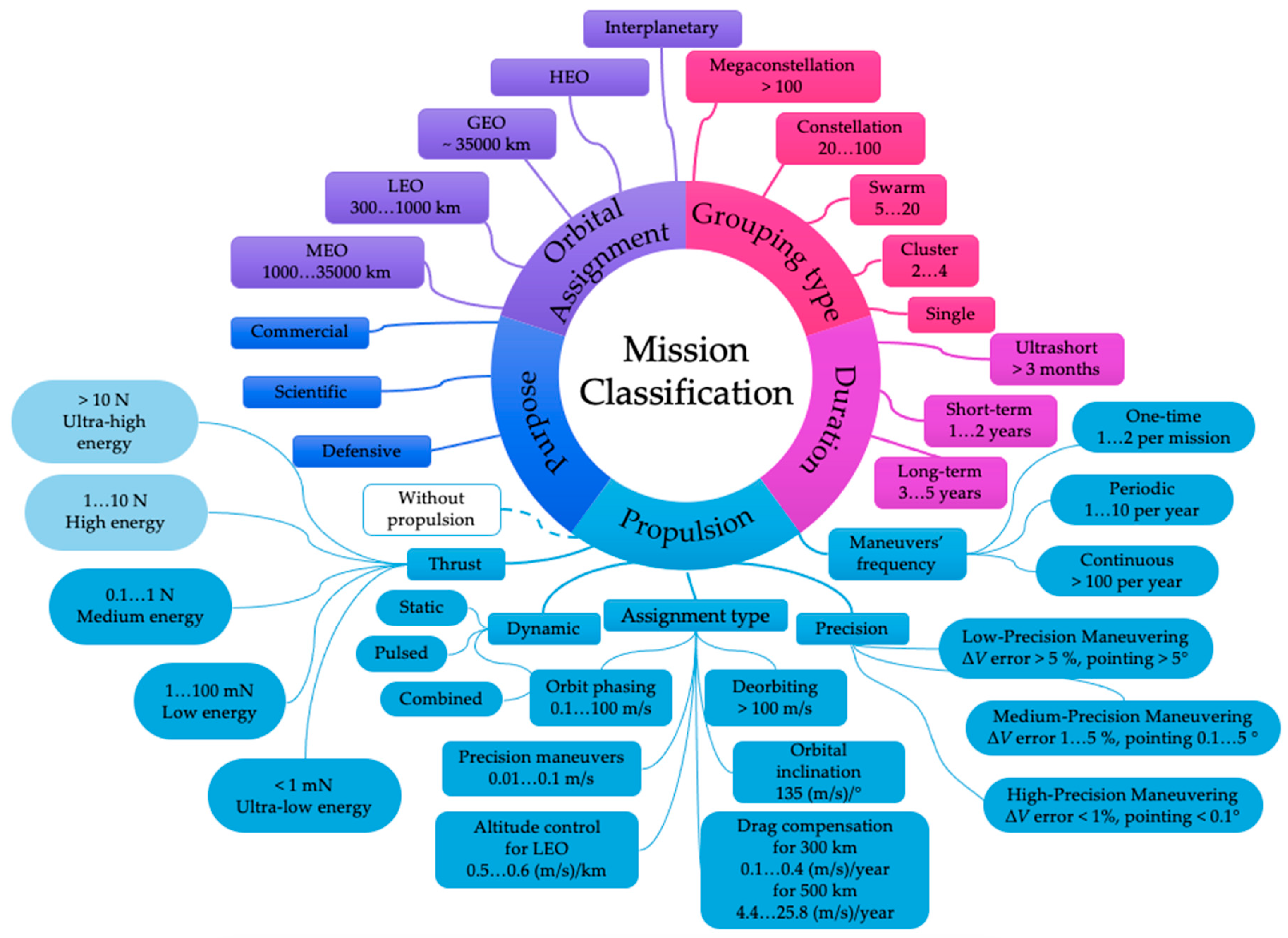
Figure 2.
Monopropellant rocket engine scheme.
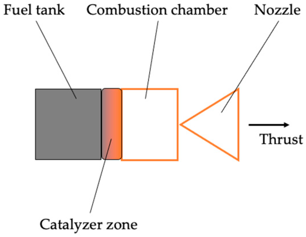
Figure 3.
Bi-propellant rocket engine scheme.
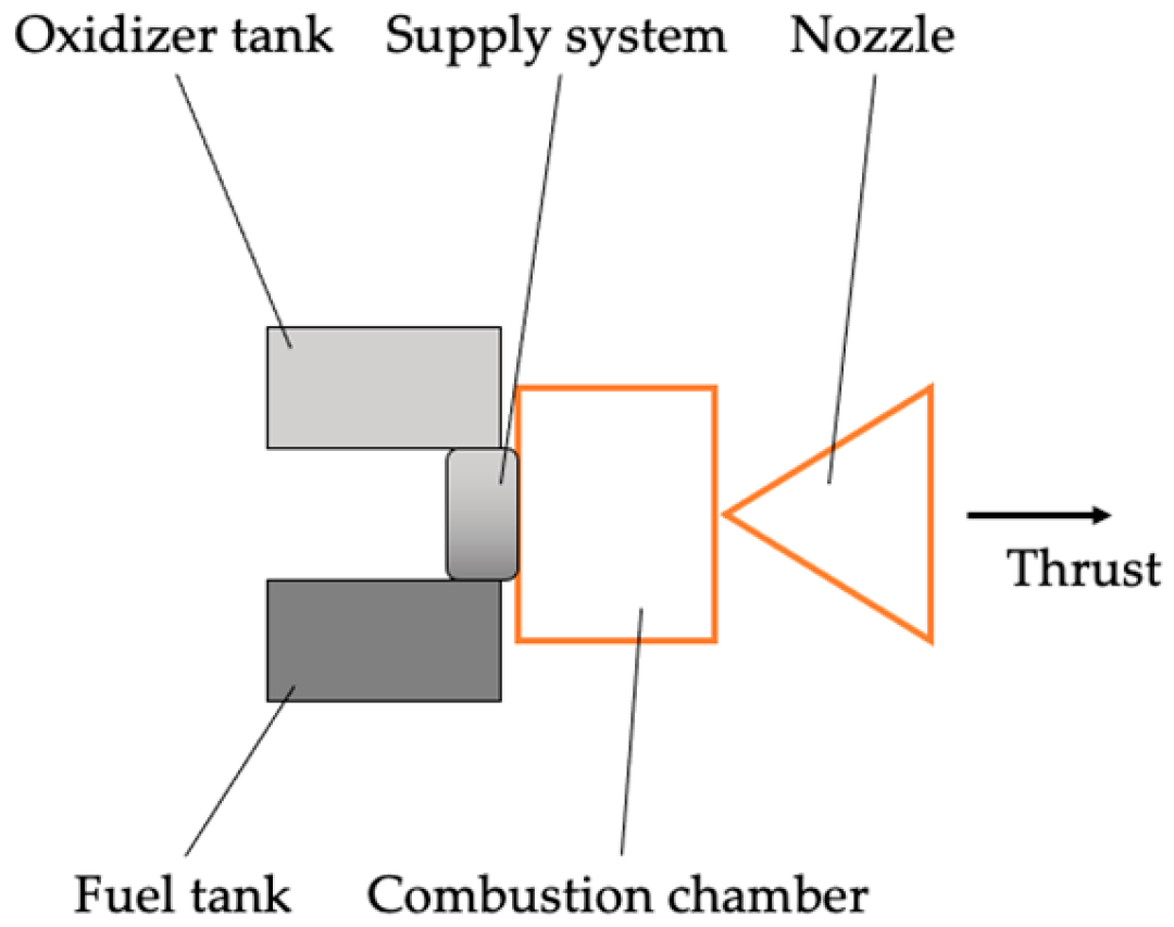
Figure 4.
Hybrid rocket engine scheme.
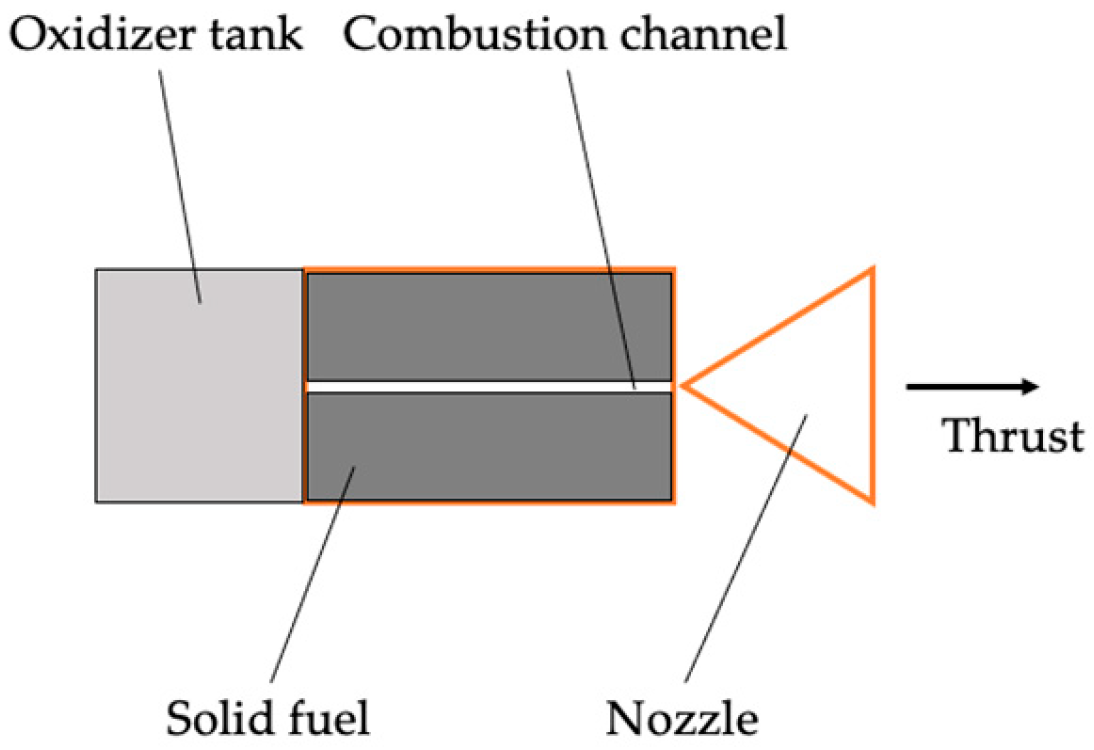
Figure 5.
Cold gas scheme.
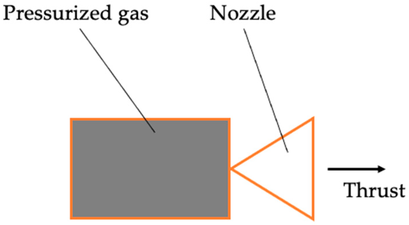
Figure 6.
Stationary plasma thruster scheme.
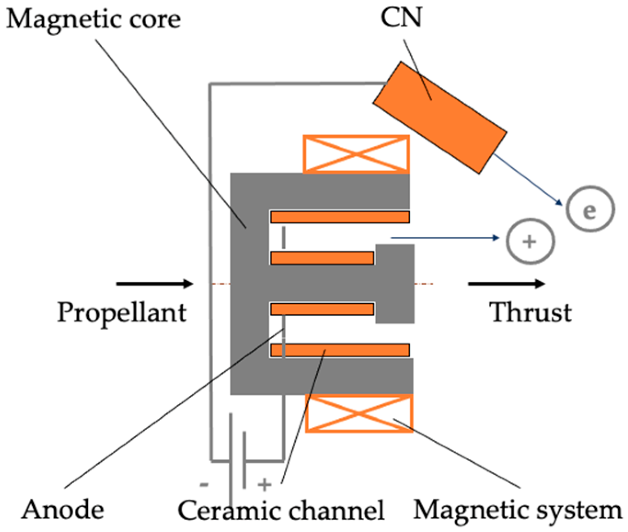
Figure 7.
Thruster with anode layer scheme.
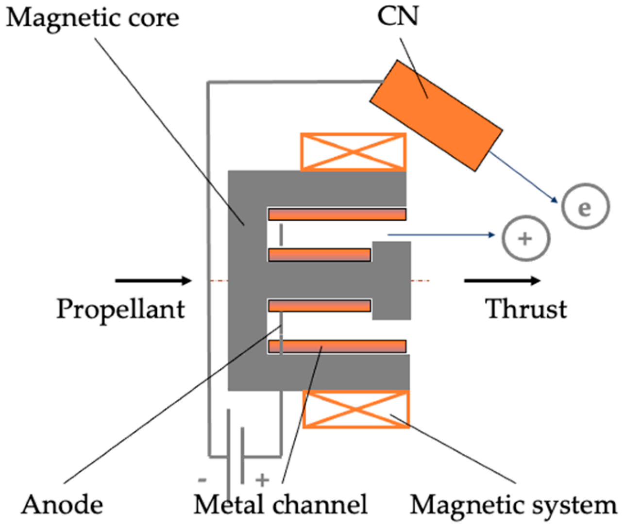
Figure 8.
RF-type ion thruster scheme.
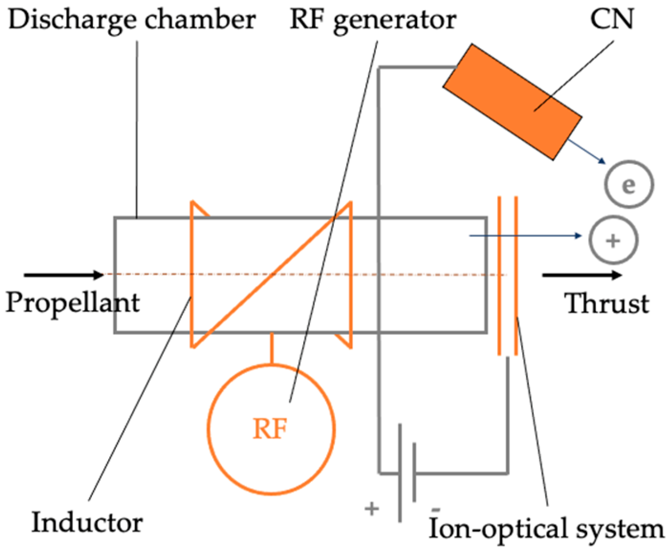
Figure 9.
Microwave-type ion thruster scheme.
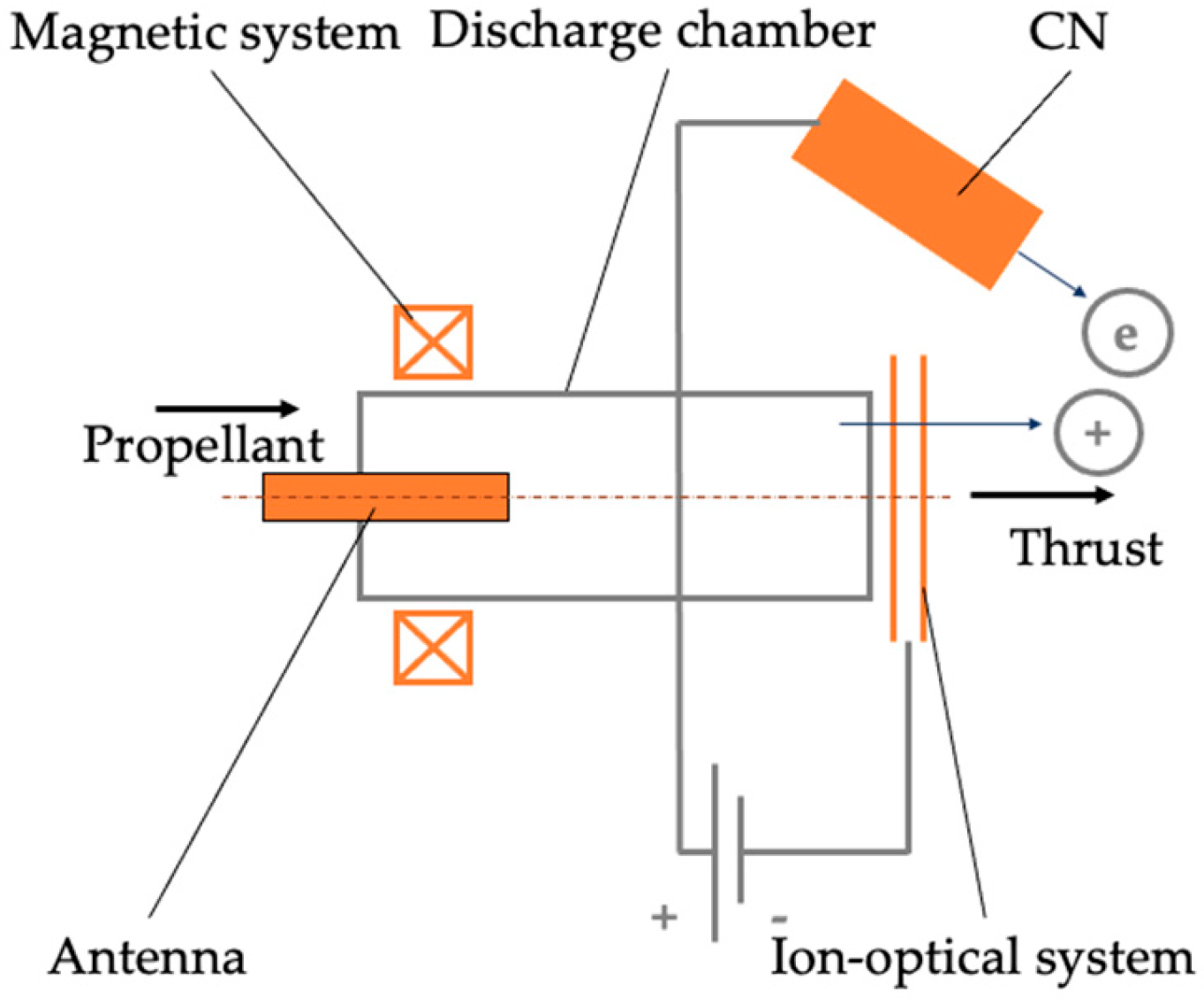
Figure 10.
Electrospray thruster scheme.
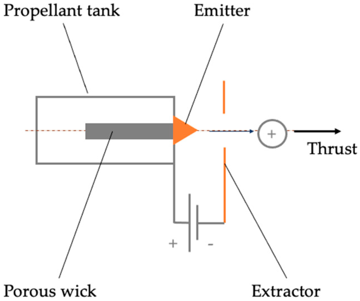
Figure 11.
Helicon plasma thruster scheme.
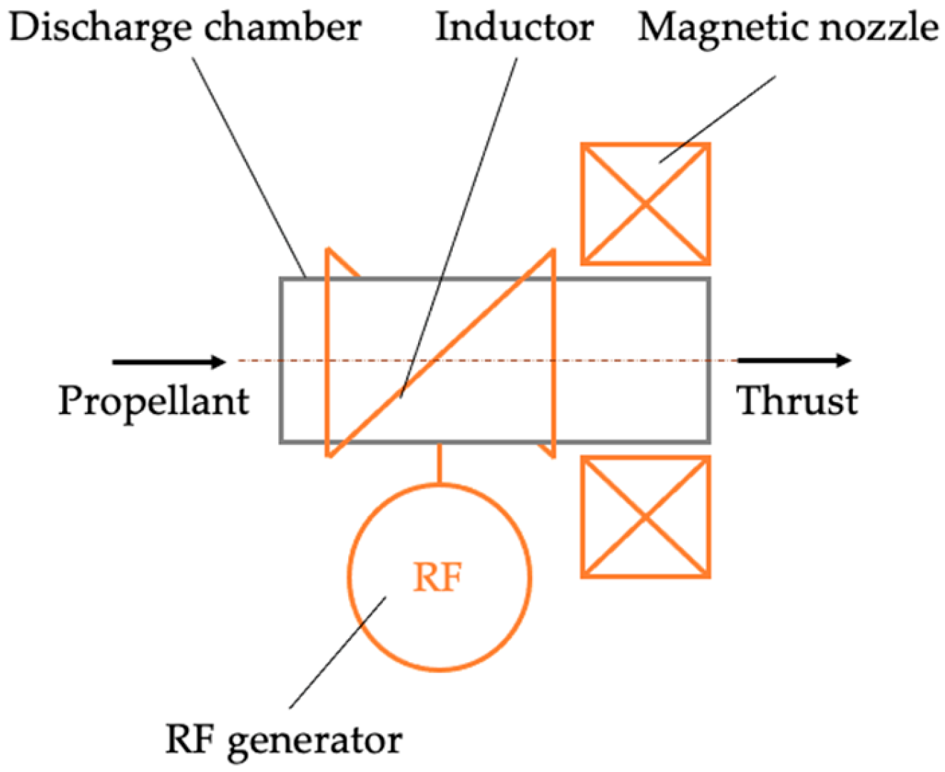
Figure 12.
Ablative pulsed plasma thruster scheme.
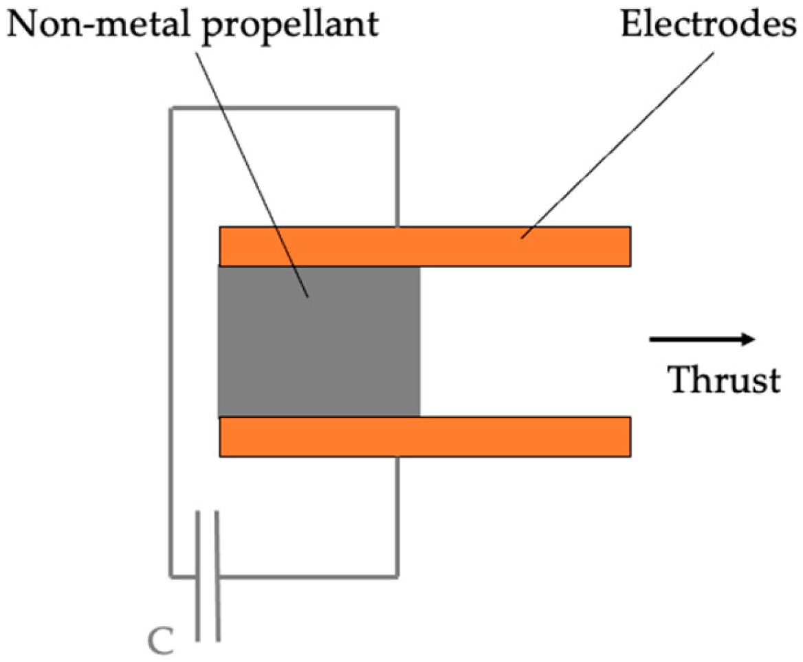
Figure 13.
Ablative pulsed plasma thruster of coaxial geometry scheme.
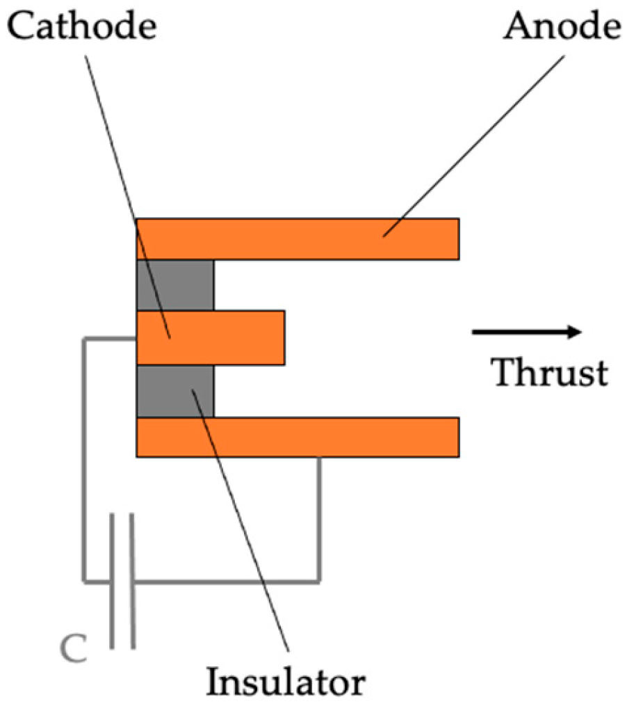
Figure 14.
Resistojet scheme.
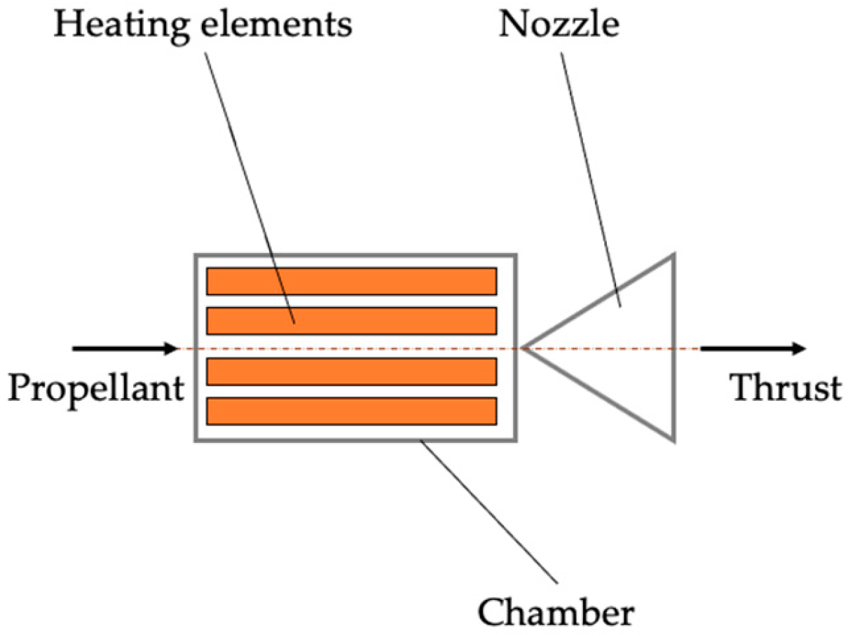
Figure 15.
Arcjet scheme.
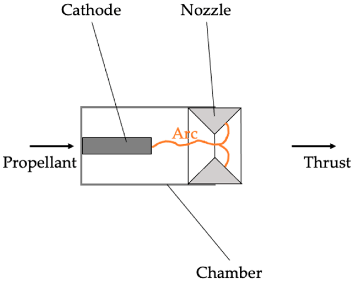
Figure 16.
Laser propulsion system scheme.
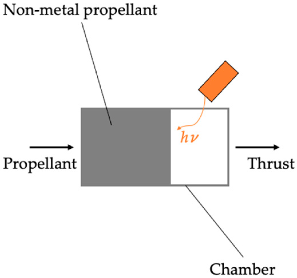
Figure 17.
Solar sail scheme.
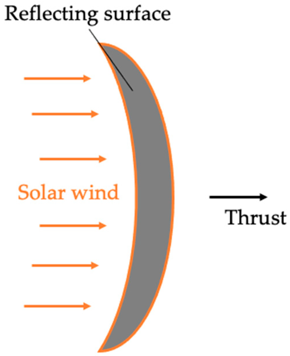
Figure 18.
Normalized distribution of use of propulsion systems aboard civil small satellites over in period from 2000 to 2024.
Figure 18.
Normalized distribution of use of propulsion systems aboard civil small satellites over in period from 2000 to 2024.
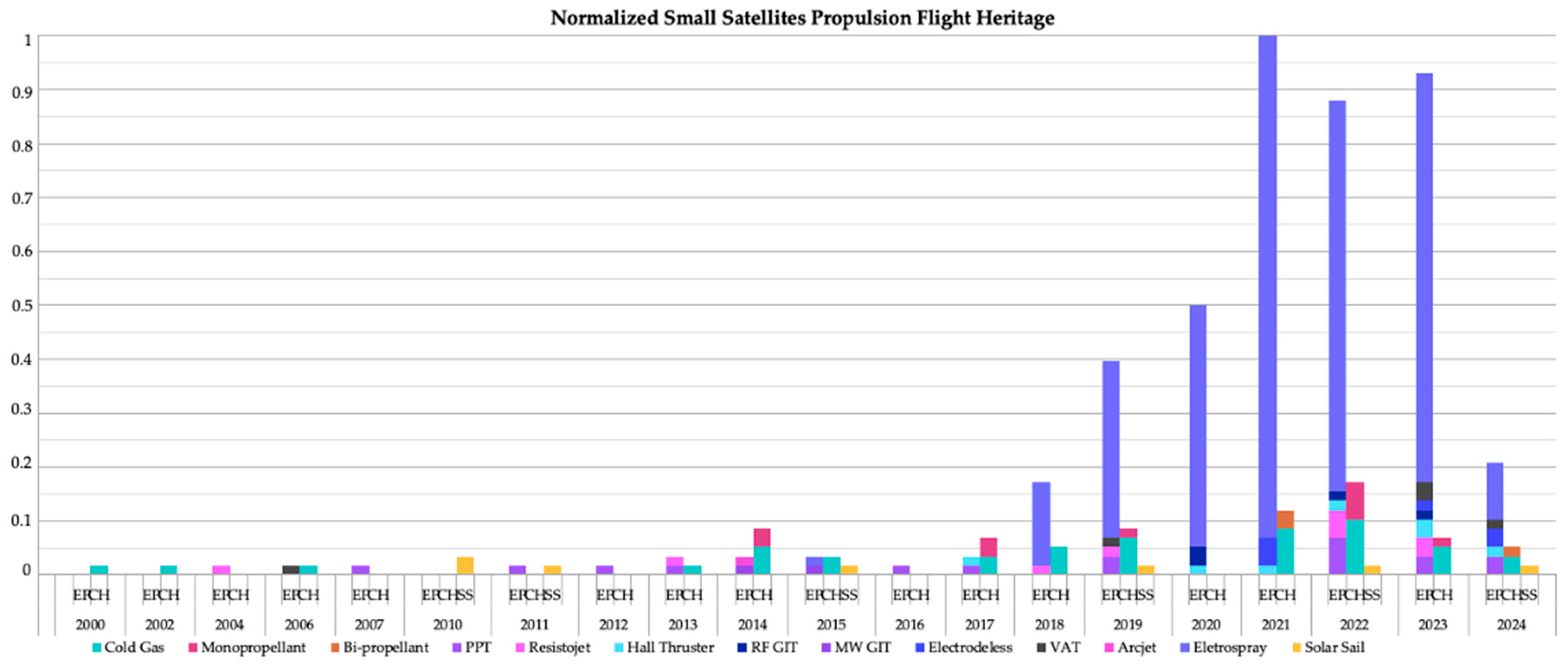
Figure 19.
Distribution of propulsion systems types used aboard small satellites in period from 2000 to 2024.
Figure 19.
Distribution of propulsion systems types used aboard small satellites in period from 2000 to 2024.
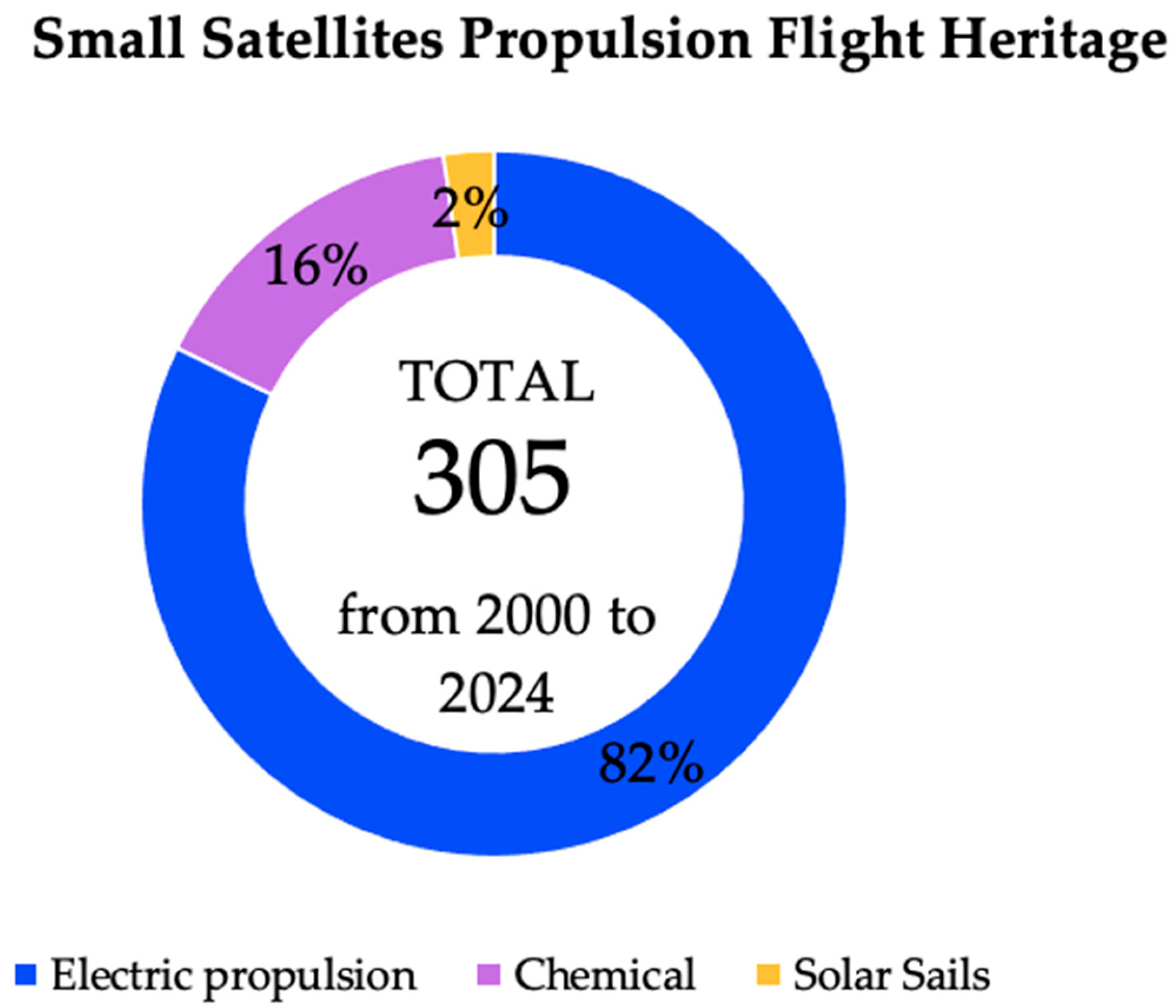
Figure 20.
Distribution of chemical propulsion types used aboard small satellites in period from 2000 to 2024.
Figure 20.
Distribution of chemical propulsion types used aboard small satellites in period from 2000 to 2024.
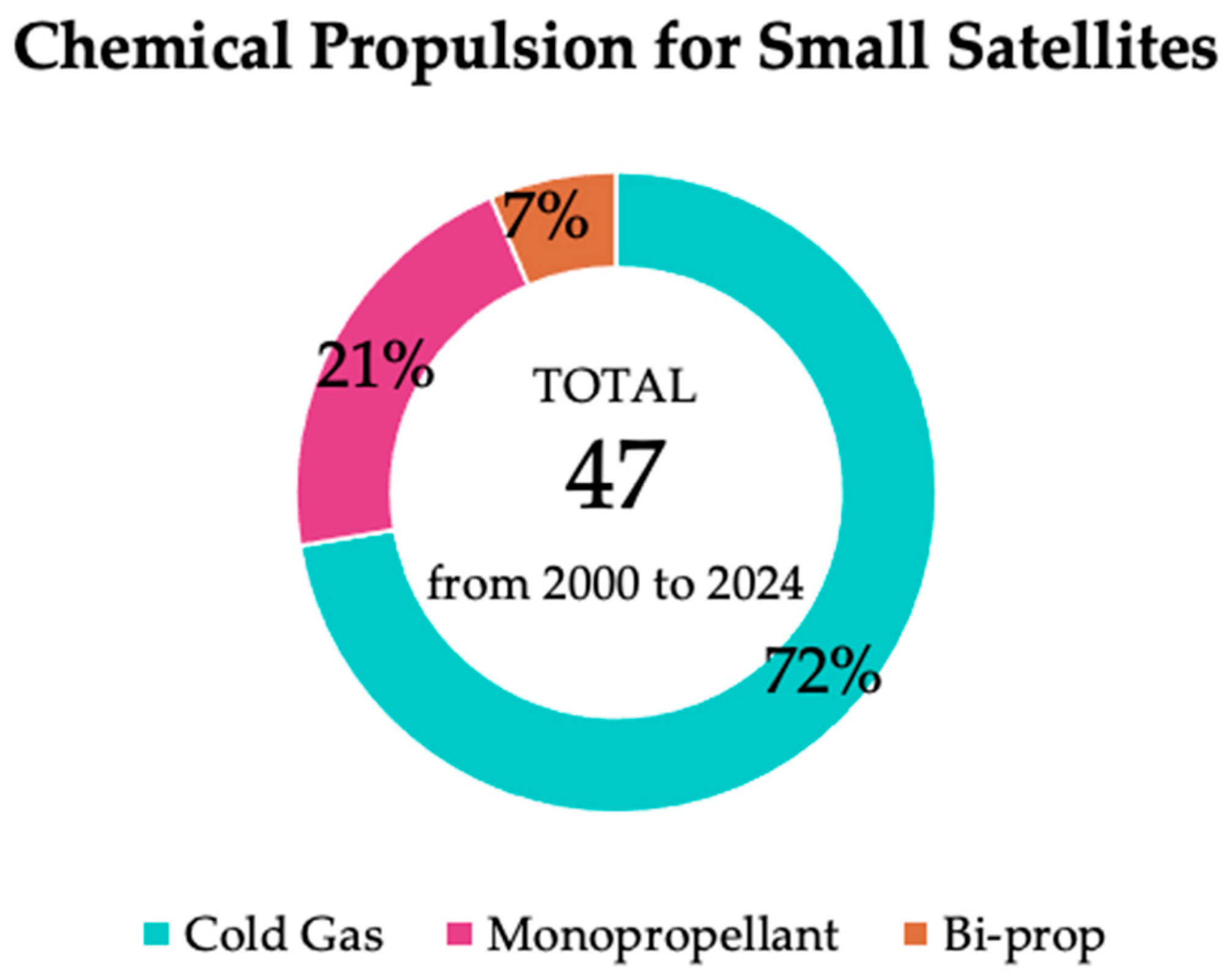
Figure 21.
Distribution of electric propulsion types used aboard small satellites in period from 2000 to 2024.
Figure 21.
Distribution of electric propulsion types used aboard small satellites in period from 2000 to 2024.
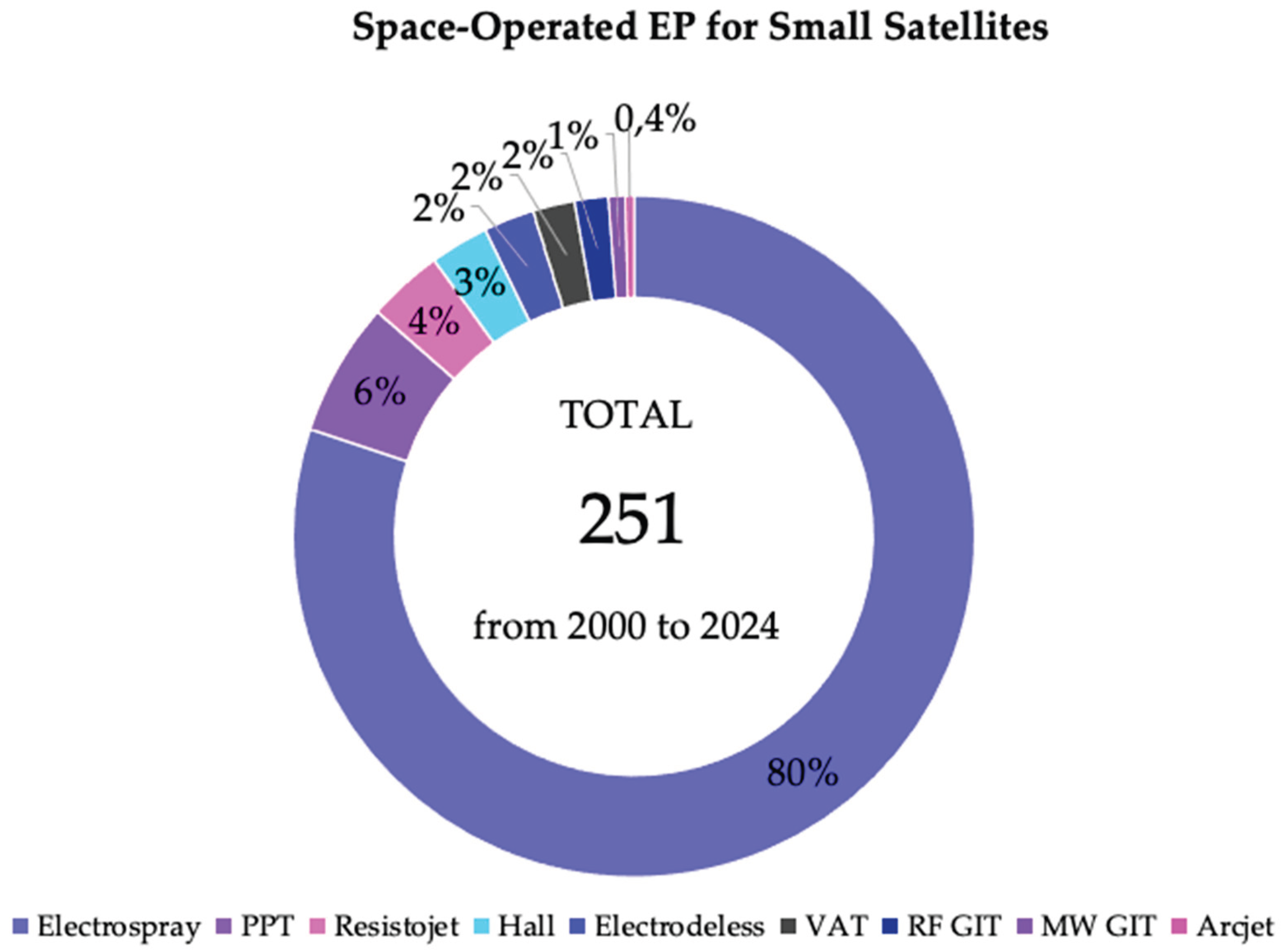
Table 6.
Flight-operated solar sails onboard small satellites.
| PS | Size | Deployment | Area, m2 | Mass, kg | Material | Launch date | Destination | NORAD ID | Ref. |
|---|---|---|---|---|---|---|---|---|---|
| IKAROS | Square, 14m × 14m | Spinning | 196 | 310 | PA | 21 May 2010 | Venus | 36577 | [132,133] |
| NanoSail-D2 | Square, 3.75m × 3.75m | Spinning | 14 | 4 | PET/Al | 20 Nov. 2010 | LEO | 37361 | [134,135] |
| LightSail 2 | Square, 5.6m × 5.6m | Spinning | 32.6 | 4.93 | PET/Al | 25 Jun. 2019 | LEO | 44420 | [136,137] |
| NEA-Scout | Square | Deploying rod | 86 | 12 | PET/Al | 16 Nov. 2022 | LEO | 57684 | [138,139] |
| ACS3 | Square, 9.9m × 9.9m | Deploying rod | 80 | 9 | PET/Al | 23 Apr. 2024 | LEO | 59588 | [140,141] |
Table 7.
Explanation of scores used.
| Score | Description |
|---|---|
| +1 | Highly understood physics processes, simplicity of development and testing, operational confidence, materials availability, production processes easiness, scientifically widespread, educationally highly available |
| 0 | Partially understood physics processes, relatively complex development and testing, operational uncertainty, limited material availability, challenging production processes, limited scientific dissemination, and limited educational accessibility |
| -1 | Poorly understood physics processes, significantly complex development and testing, persisting operational challenges, scarce material availability, challenging production processes, restricted scientific dissemination, and restricted educational accessibility |
Table 8.
Physics rationale of trends in propulsion technologies for small satellites.
| Propulsion type | Processes understanding | Physics description | Testing validation | Overall score |
|---|---|---|---|---|
| Monopropellant rocket | 1 | 1 | 1 | 3 |
| Bi-propellant rocket | 1 | 1 | 1 | 3 |
| Hybrid rocket | 0 | 0 | 1 | 1 |
| Cold gas | 1 | 1 | 1 | 3 |
| HET | 0 | 1 | 1 | 2 |
| IT | 1 | 1 | 1 | 1 |
| Electrospray | 1 | 1 | 1 | 3 |
| PPT | 0 | 0 | 0 | 0 |
| VAT | 0 | 0 | 0 | 0 |
| EPT | 0 | 0 | 1 | 1 |
| Resistojet | 1 | 1 | 1 | 3 |
| Arcjet | 1 | 1 | 1 | 3 |
| Laser propulsion | 1 | 1 | 1 | 3 |
| Solar sail | 1 | 1 | 1 | 3 |
Table 9.
Engineering rationale of trends in propulsion technologies for small satellites.
| Propulsion type | Development effort | Testing effort | Integration effort | TVC realization | Overall score |
|---|---|---|---|---|---|
| Monopropellant rocket | 1 | 0 | 0 | 1 | 2 |
| Bi-propellant rocket | 1 | 0 | 0 | 1 | 2 |
| Hybrid rocket | 0 | 0 | 0 | 1 | 2 |
| Cold gas | 1 | 1 | 1 | 1 | 4 |
| HET | 0 | 1 | 0 | 0 | 1 |
| IT | 0 | 1 | 0 | 0 | 1 |
| Electrospray | 0 | 1 | 1 | 1 | 3 |
| PPT | 0 | 0 | -1 | 0 | -1 |
| VAT | 0 | 0 | -1 | -1 | -2 |
| EPT | 0 | 1 | 1 | 1 | 3 |
| Resistojet | 1 | 0 | 0 | 1 | 2 |
| Arcjet | 1 | 0 | 0 | 1 | 2 |
| Laser propulsion | 0 | 1 | 1 | 1 | 3 |
| Solar sail | 1 | -1 | 0 | 1 | 1 |
Table 10.
Operational rationale of trends in propulsion technologies for small satellites.
| Propulsion type | Specific mass/volume | Specific impulse | Thrust adjustability | Overall score |
|---|---|---|---|---|
| Monopropellant rocket | 1 | -1 | 0 | 0 |
| Bi-propellant rocket | 1 | -1 | 0 | 0 |
| Hybrid rocket | 1 | -1 | 1 | 1 |
| Cold gas | 1 | -1 | 1 | 1 |
| HET | 0 | 0 | 1 | 1 |
| IT | 1 | 1 | 0 | 2 |
| Electrospray | 0 | 1 | 1 | 2 |
| PPT | 0 | 0 | 0 | 0 |
| VAT | 0 | 0 | 0 | 0 |
| EPT | 1 | 0 | 1 | 2 |
| Resistojet | 1 | 0 | 1 | 2 |
| Arcjet | 1 | 0 | 1 | 2 |
| Laser propulsion | 1 | 1 | 0 | 2 |
| Solar sail | -1 | 0 | -1 | -2 |
Table 11.
Production rationale of trends in propulsion technologies for small satellites.
| Propulsion type | Materials availability | Processes of production | Storage simplicity | Overall score |
|---|---|---|---|---|
| Monopropellant rocket | 1 | 1 | 0 | 2 |
| Bi-propellant rocket | 1 | 1 | 0 | 2 |
| Hybrid rocket | 1 | 0 | 0 | 1 |
| Cold gas | 1 | 1 | 0 | 2 |
| HET | 0 | 0 | 0 | 0 |
| IT | 0 | 0 | 0 | 0 |
| Electrospray | 1 | 0 | 1 | 2 |
| PPT | 1 | 0 | 1 | 2 |
| VAT | 1 | 0 | 1 | 2 |
| EPT | 1 | 1 | 0 | 2 |
| Resistojet | 1 | 1 | 0 | 2 |
| Arcjet | 1 | 1 | 0 | 2 |
| Laser propulsion | 1 | 0 | 0 | 1 |
| Solar sail | 1 | 0 | 1 | 2 |
Table 12.
Societal rationale of trends in propulsion technologies for small satellites.
| Propulsion type | Historical legacy | Scientific prevalence | Educational outreach | Overall score |
|---|---|---|---|---|
| Monopropellant rocket | 1 | 1 | 1 | 3 |
| Bi-propellant rocket | 1 | 1 | 1 | 3 |
| Hybrid rocket | 0 | 0 | 0 | 0 |
| Cold gas | 1 | 1 | 1 | 3 |
| HET | 1 | 1 | 1 | 3 |
| IT | 1 | 1 | 1 | 3 |
| Electrospray | 0 | 0 | 0 | 0 |
| PPT | 1 | 1 | 1 | 3 |
| VAT | 0 | 0 | 0 | 0 |
| EPT | 1 | 0 | 0 | 1 |
| Resistojet | 1 | 1 | 1 | 3 |
| Arcjet | 1 | 1 | 1 | 3 |
| Laser propulsion | 0 | 0 | 0 | 0 |
| Solar sail | 0 | 0 | 0 | 0 |
Table 13.
Overall development and using rationales for propulsion technologies for small satellites.
Table 13.
Overall development and using rationales for propulsion technologies for small satellites.
| Propulsion type | Overall score |
|---|---|
| Monopropellant rocket | 10 |
| Bi-propellant rocket | 10 |
| Hybrid rocket | 5 |
| Cold gas | 13 |
| HET | 7 |
| IT | 7 |
| Electrospray | 10 |
| PPT | 4 |
| VAT | 0 |
| EPT | 9 |
| Resistojet | 12 |
| Arcjet | 12 |
| Laser propulsion | 9 |
| Solar sail | 4 |
Disclaimer/Publisher’s Note: The statements, opinions and data contained in all publications are solely those of the individual author(s) and contributor(s) and not of MDPI and/or the editor(s). MDPI and/or the editor(s) disclaim responsibility for any injury to people or property resulting from any ideas, methods, instructions or products referred to in the content. |
© 2026 by the authors. Licensee MDPI, Basel, Switzerland. This article is an open access article distributed under the terms and conditions of the Creative Commons Attribution (CC BY) license (http://creativecommons.org/licenses/by/4.0/).
Copyright: This open access article is published under a Creative Commons CC BY 4.0 license, which permit the free download, distribution, and reuse, provided that the author and preprint are cited in any reuse.


