Submitted:
21 January 2026
Posted:
22 January 2026
You are already at the latest version
Abstract
Ni@TiO₂ core–shell nanoparticles were synthesized by magnetron sputtering and their structure verified by HRTEM and EDS analysis. The thermal stability of these particles was investigated using in situ TEM annealing and compared with that of pure Ni nanoparticles. While pure Ni particles sinter already at 450 °C and exhibit significant growth at 800 °C, Ni@TiO2 nanoparticles remain stable up to 700 °C, with the sintering onset between 700 and 800 °C. A simple thermal-mismatch model was applied to explain the stabilizing effect of the TiO2 shell, demonstrating that differences in thermal expansion between Ni and TiO2 generate interface stresses sufficient to crack the shell after the amorphous–rutile transformation. The TiO2 coating effectively delays Ni coalescence by 250 °C relative to bare Ni, highlighting its role as a protective shell against high-temperature sintering.
Keywords:
nickel nanoparticles
; TiO2 coating
; core–shell nanoparticles
; thermal stability
; sintering
; in situ TEM
1. Introduction
Nanotechnology has significantly broadened capabilities in numerous fields over the last decade by creating functional systems at the nanoscale, primarily in the form of nanoparticles [1]. Notably, Nickel nanoparticles (NiNPs) have attracted significant interest due to their distinctive magnetic, chemical, and physical properties, including high reactivity, operational simplicity, biocompatibility, bacterial resistance, cost-effectiveness, abundance, anti-inflammatory effects, and environmental compatibility [2]. These properties offer a potential for their applications in a variety of fields, including catalysis [3], production of batteries [4], applications in optical switches [5], direct immobilization of biomolecules via magnetic properties [6], or sintering additives in coatings, plastics, and fibers [7,8].
Nickel nanoparticles are prone to agglomeration due to their high surface energy [9]. This agglomeration can reduce effectiveness in applications where high surface area is critical, such as catalysis and sensor technologies. NiNPs sintering is particularly problematic at elevated temperatures [10,11], which are often required in industrial processes. The particles lose their distinct nanoparticle properties, effectively diminishing their catalytic activity, primarily due to changes in their surface area [12] and magnetic properties [13] as their magnetic domain structures change.
A variety of strategies have been developed to address these issues, including surface modification [14,15] and incorporating nanoparticles into or onto stable matrices [16]. For instance, carbon-coated Ni nanoparticles remain ferromagnetic up to 127 °C [17]. Additionally, Ni@SiO2 nanoparticles can withstand high temperatures up to 700 °C [18]. Alumina-coated NiO nanopowders also show a significant enhancement in catalytic activity at elevated temperatures ranging from 700 to 800 °C [19], compared to their uncoated counterparts.
In this study, the impact of an amorphous titanium dioxide (TiO2) shell on the sintering behavior of nickel (Ni) nanoparticles is explored. Magnetron sputtering was used to fabricate Ni@TiO2 core-shell nanoparticles, employing two planar magnetron sources for deposition. In situ transmission electron microscopy (TEM) was used to observe and analyze sintering behavior directly. This observation enabled a comparative analysis of the behavior of pure Ni nanoparticles and their Ni@TiO2 core-shell counterparts.
2. Materials and Methods
The system for producing core-shell nanoparticles consisted of a primary gas aggregation cluster source (GAS) for producing Ni NPs and a secondary chamber for coating them with a Ti film. The primary GAS featured a water-cooled aggregation chamber, 100 mm in diameter, and a DC planar magnetron, 81 mm in diameter, equipped with a 1.5 mm thick Ni target. The corresponding working pressure was 48 Pa. The secondary chamber contained another DC magnetron with an 81 mm diameter and a 4 mm thick Ti target (purity 99.2%). Both magnetrons operated under constant current, using Ar (purity 99.996% ) as the working gas. More details about the experimental setup can be found in the work by Hanus et al. [20].
The nanoparticles were sputtered on a glass substrate. The TEM samples were prepared by dropping the nanoparticles, suspended in methanol, onto a grid with a lacey carbon support film. A transmission electron microscope JEOL 2200FS (JEOL Ltd., Japan), operating in TEM and STEM (scanning transmission electron microscopy) modes, with bright-field (BF), high-angle annular dark field (HAADF), and secondary-electron (SE) detectors, was used. The annealing was done in a Gatan in situ heating holder. Selected-area electron diffraction (SAED) patterns were analyzed using the JEMS software package [21].
For the simulation part, polycrystalline rutile shells were constructed using Atomsk [22]. The shells were stabilized at 700 °C, while a spherical indenter placed inside the empty shell expanded at a rate of 2 nm/s. All simulations were performed using the LAMMPS software [23], Ti–O interactions were modeled with the Matsui–Akagoi potential [24], which has been widely applied to TiO2 polymorphs [25]. The results were visualized and analyzed using OVITO [26].
3. Results
3.1. Pure Ni Nanoparticles
The characterization of Ni nanoparticles (Figure 1) revealed a mean diameter of approximately 9 nm. The diffraction pattern analysis confirmed that the nanoparticles possess a face-centered cubic (fcc) structure. Additionally, energy-dispersive X-ray spectroscopy (EDS) maps indicated that the nanoparticles have a Ni core surrounded by a thin oxidized shell.
The particles were annealed to 100 °C, then in 50 °C increments to 850 °C. Each temperature was held for 5 minutes. The annealing process and its effects on an agglomerate of NiNPs are documented in Figure 2. The particles maintained their original shape up to 400 °C. At 450 °C, significant sintering commenced, as evidenced by the necking between neighboring nanoparticles and the coalescence of smaller particles into larger ones. This coalescence increased the average nanoparticle size to 13 nm. These results are consistent with other studies, which report substantial sintering of Ni nanoparticles with mean sizes of 9 nm and 20 nm at around 450 °C [27,11]. A further notable change in the shape of the nanoparticles occurred at 800 °C, when they grew to diameters ranging from 15 to 30 nm.
3.2. Core-Shell NiTi Nanoparticles
The core-shell structure of nanoparticles, consisting of a nickel core coated with titanium using magnetron sputtering, was confirmed by STEM analysis (Figure 3). The nanoparticles have a mean diameter of 24 nm, with a core diameter close to 20 nm and a shell thickness of 2 nm. The HAADF detector showed a brighter core in the image, indicating that the atoms in the core are heavier. This finding aligns with the EDS analysis, which clearly distinguishes the Ni core from the Ti shell (Figure 3f and Figure 3g). Additionally, oxidation of the Ti shell was observed (Figure 3h).
Figure 4 shows HRTEM images of the structure of the nanoparticles. The hexagonal close-packed (hcp) structure of the core is confirmed by Fast Fourier Transform (FFT) images, which were compared to JEMS-simulated diffraction images in several orientations. No crystalline structure was detected in the shell, indicating that the titanium oxide (TiO2) shell is amorphous.
Figure 5 shows the annealing process of an agglomerate of core-shell Ni@TiO2 nanoparticles. Bright-field and secondary-electron detectors were used to capture the projection and surface of the agglomerate. The agglomerate remains stable up to 700 °C, with no visible changes in particle shape, size, or surface characteristics. Initial sintering occurs between 700 °C and 800 °C, with considerable necking and particle merging observed at 800 °C. The particles further grow as the temperature increases to 900 °C.
The analysis of the particles formed after the sintering of Ni@TiO2 core-shell nanoparticles (Figure 5) reveals a separation of Ni and Ti components. EDS analysis confirmed that newly formed particles, with diameters reaching up to 100 nm, are primarily composed of Ni. The HAADF image shows that the TiO2 shells have merged into the background, forming a thinner TiO2 layer.
Figure 6.
Images of a representative nanoparticle cluster after annealing: a) STEM HAADF, b-d) EDS maps of different elements (Ti, Ni, O), e) overlay of the EDS maps (Ti, Ni, O).
Figure 6.
Images of a representative nanoparticle cluster after annealing: a) STEM HAADF, b-d) EDS maps of different elements (Ti, Ni, O), e) overlay of the EDS maps (Ti, Ni, O).
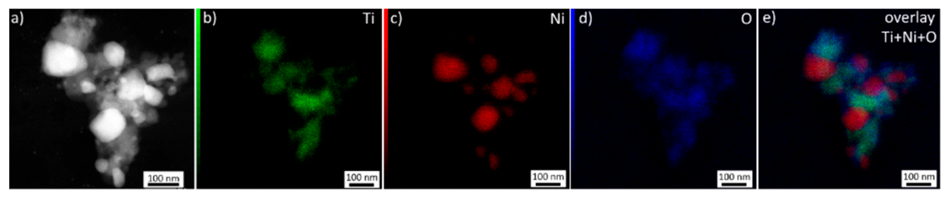
Figure 7 presents a detailed analysis of the core–shell evolution at elevated temperatures. HRTEM images reveal that the initially amorphous shell begins to crystallize between 500 and 600 °C, with lattice spacings indicative mainly of the rutile phase. A detailed analysis of the diffraction pattern from a larger area (Figure 7e) confirms the presence of nickel along with a rutile and minor brookite shell.
4. Discussion
The in-situ TEM experiments show that Ni@TiO2 particles remain morphologically stable up to ~700 °C, with the shell failure and the Ni coalescence emerging between 700 and 800 °C. This stabilization window aligns with earlier reports that TiO₂ coatings substantially suppress Ni sintering. Specifically, TiO₂-coated Ni powders/compacts prepared by wet chemistry exhibit markedly reduced sinterability and require temperatures ≥150–200 °C higher than bare Ni to achieve comparable densification [28]. Likewise, for Ni@TiO₂ 'nanocapsules', thermomechanical and short-dwell annealing data show that, relative to bare Ni (shrinkage onset ~657 °C), the TiO₂ shell shifts the observed sintering onset by ~200–300 °C [29].
For tens-of-nanometer Ni cores with few-nanometer shells, TiO₂ performs on par with SiO₂ and Al₂O₃ prepared by atomic layer deposition in delaying coalescence into the high-temperature window. In our case (~2 nm TiO₂ on ~20 nm Ni), sintering is held off until ~700–800 °C. With a comparably thin alumina overcoat, an ~4 nm Al₂O₃ layer on Ni/SiO₂ confines Ni growth and maintains stability during high-temperature operation (700–800 °C range), attributed to the overcoat physically restraining Ni migration [30]. Likewise, thin-shell Ni@SiO₂ core–shell particles developed for high-temperature solar absorbers remain morphologically stable at ~700 °C, indicating a similar level of thermal suppression with silica at a few nm thickness [31]. Altogether, when shell thickness is kept in the ~2–4 nm band, and Ni cores are ~10–30 nm, the onset temperature for visible sintering clusters is around ~700–800 °C across TiO₂, SiO₂, and Al₂O₃, with exact thresholds shifting with shell porosity, continuity, and atmosphere.
Sintering of pure Ni and TiO2 nanoparticles within this temperature range is generally considered to be a process controlled by surface diffusion [10,32]. The onset of sintering observed between 700 and 800 °C occurs well below the temperatures typically required for TiO₂ nanoparticles to sinter [33,34,35]. In the experiment, the formation of large Ni particles was observed without interaction with the TiO2 shell. This observation suggests that the Ni was trapped in the cores, and sintering was possible after the deterioration of the TiO2 shell. This suggestion is supported by the HRTEM images captured at elevated temperatures (Figure 8), which show that shell deterioration is already evident at several locations, exposing the Ni core.
The deterioration is therefore caused by the combination of mechanical rupture of the shell due to thermal expansion differences and consequent diffusion-based shrinking of the ruptured shell to minimize surface energy. The rupture of the shell due to mechanical stress at elevated temperatures was further examined using molecular dynamics simulations. At a core expansion of approximately 2 Å, corresponding to the end of the elastic regime, the stress reaches about 100 MPa. With further expansion, the stress increases to approximately 250 MPa at around 9 Å, where the onset of a large, visible crack and the opening of the shell are observed. In the intermediate expansion range between these two values, local damage in the form of small microvoids within the shell is observed. These defects do not fully penetrate the shell but are accompanied by irregular thinning of the shell and changes in surface morphology. In the presence of the nickel core, such defects are expected to enhance diffusion pathways locally prior to complete shell failure.
The stress at the core-shell interface can be evaluated using a simple model based on the differences in thermal expansion coefficients of Ni and TiO2. At room temperature, it is assumed that a contact layer exists between the Ni core and the surrounding TiO2 shell. Notably, the linear thermal expansion coefficient α of nickel is greater than that of TiO2 (αTiO2 in the range (8.4 – 11.8)*10-6 K-1 and αNi = (12 - 13.5)*10-6 K-1) [36,37]. This difference in thermal expansion increases tension in the contact layer as temperature rises.
The maximum pressure that causes volumetric deformation of the Ni core and contraction of the Ni side of the contact layer can be approximated as the tensile strength of TiO2. Then, the deformation ɛNi that leads to the total deformation observed in the inner part of the TiO2 layer at the point of fracture can be calculated as:
. (1)
We assume that the mechanical properties, namely the Young's modulus ETiO2 (value in the range 230 - 288 GPa), and the bulk modulus of Ni BNi (value in the range 162 - 200 GPa) [38,39], remain constant across the temperature range considered. Additionally, we assume that the linear coefficients of thermal expansion remain constant. Then we can estimate the interface pressure as:
. (2)
On the nanoscale, elastic constants may deviate from bulk values. Using the bond energy model of Pandey and Kumar [40], the bulk modulus of Ni nanoparticles decreases only slightly (from 180 to 170 GPa for 20 nm), suggesting minimal size effect. Young's modulus is also reduced in thin films, but even for shell thicknesses <5 nm, it remains above ~80% of the bulk value [41,42].
Figure 9.
Average shell stress as a function of core radius expansion for a 10 nm large shell with 2 nm thickness. Visualizations of the shell sliced in half at the initial state and after the appearance of a visible crack are shown (A, D). 5 nm thick slices are shown for 4 different radius values (A-D).
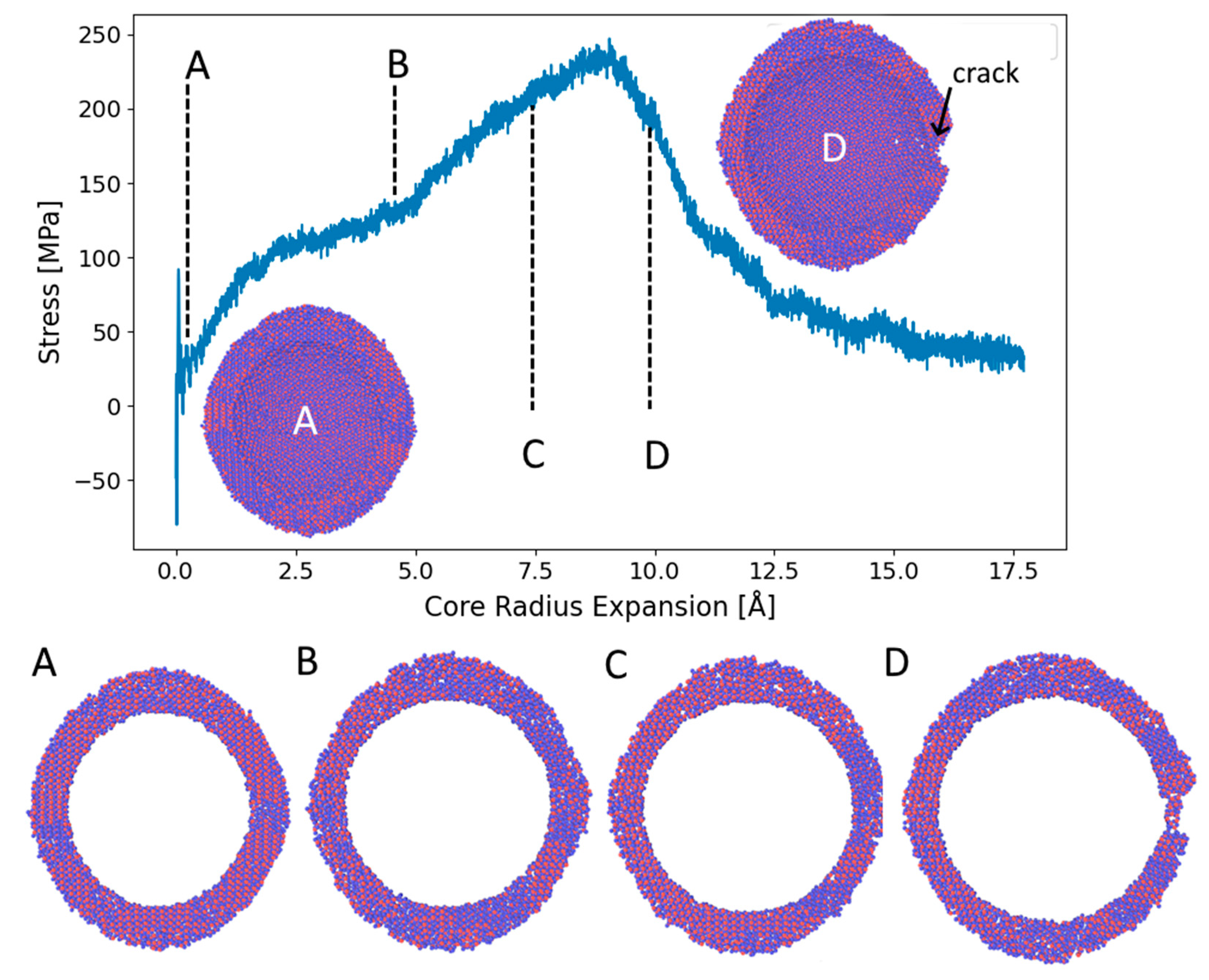
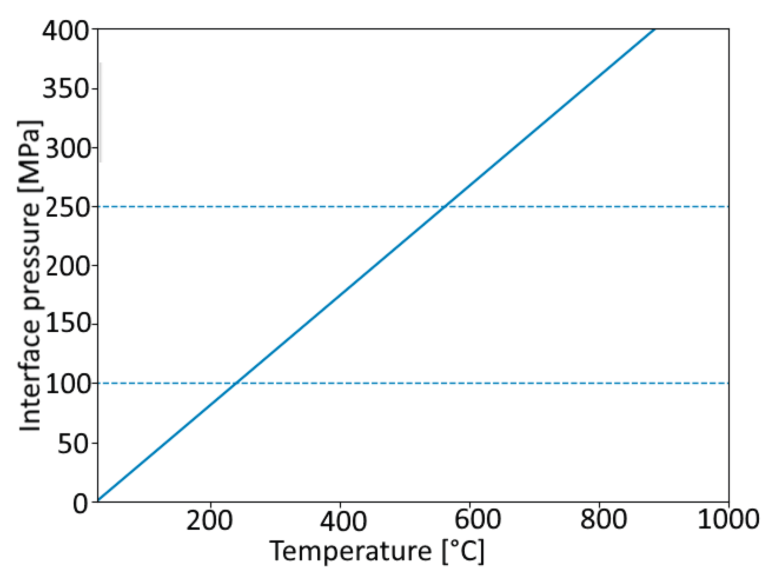
The temperature dependence of the interface pressure computed from the average values of the material constants is shown in Figure 10. The pressure limit for crack formation (250 MPa) is reached at around 600°C, which is close to the temperature at which the first cracks were observed in the experiment. Despite the simplicity of the model and the absence of explicit phase transformations, the estimated cracking temperature is in reasonable agreement with the experimental observations.
5. Conclusions
In this study, the sintering behavior of Ni@TiO₂ core-shell nanoparticles was investigated, with a focus on how the TiO₂ shell affects their stability and sintering resistance. Compared to pure Ni nanoparticles that began to sinter at 450°C, the Ni@TiO₂ nanoparticles remained stable up to 700°C, with initial sintering observed between 700°C and 800°C. After shell rupture, the Ni cores coalesce into larger Ni particles, confirming that the shell acts as a confinement barrier up to its mechanical failure. Molecular dynamics simulations and a thermal-mismatch model indicate that the interfacial stresses induced by the thermal expansion difference between Ni and TiO₂ are sufficient to drive shell cracking once the amorphous shell crystallizes to rutile. Overall, the TiO₂ shell effectively suppresses sintering, extending the operational stability of Ni nanoparticles by ~250 °C and offering a promising route for designing thermally robust core–shell nanostructures.
Author Contributions
Lucia Bajtošová: Writing – review & editing, Writing – original draft, Methodology, Investigation, Data curation. Nikoleta Štaffenová: Investigation, Data curation. Elena Chochoľaková: Investigation, Data curation. Jan Hanuš: Investigation. Vladimír Šíma: Investigation, Methodology. Miroslav Cieslar: Writing – review & editing, Supervision.
Funding
We acknowledge the funding and support from the Czech Science Foundation, grant number 22-22572S.
Data Availability Statement
All data included in this study are available upon request by contacting the corresponding author.
Conflicts of Interest
The authors declare no conflicts of interest. The funders had no role in the design of the study, in the collection, analysis, or interpretation of data, in the writing of the manuscript, or in the decision to publish the results.
References
- Altammar, K.A. A review on nanoparticles: Characteristics, synthesis, applications, and challenges. Front. Microbiol. 2023, 14, 1155622. [Google Scholar] [CrossRef]
- Tailor, G.; Chaudhary, J.; Jandu, S.; Chetna; Mehta, C.; Yadav, M.; Verma, D. A review on green route synthesized nickel nanoparticles: Biological and photo-catalytic applications. Results Chem. 2023, 6, 101195. [Google Scholar] [CrossRef]
- Bibi, I.; Kamal, S.; Ahmed, A.; Iqbal, M.; Nouren, S.; Jilani, K.; et al. Nickel nanoparticle synthesis using Camellia sinensis as reducing and capping agent: Growth mechanism and photocatalytic activity evaluation. Int. J. Biol. Macromol. 2017, 103, 783–790. [Google Scholar] [CrossRef]
- Cheng, Y.; Guo, M.; Zhai, M.; Yu, Y.; Hu, J. Nickel nanoparticles anchored onto Ni foam for supercapacitors with high specific capacitance. J. Nanosci. Nanotechnol. 2020, 20, 2402–2407. [Google Scholar] [CrossRef] [PubMed]
- Reena Mary, A.P.; Suchand Sandeep, C.S.; Narayanan, T.N.; Philip, R.; Moloney, P.; Ajayan, P.M.; et al. Nonlinear and magneto-optical transmission studies on magnetic nanofluids of non-interacting metallic nickel nanoparticles. Materials 2011, 22, 375702. [Google Scholar] [CrossRef] [PubMed]
- Bârsan, M.M.; Enache, T.A.; Preda, N.; Stan, G.; Apostol, N.G.; Matei, E.; et al. Direct immobilization of biomolecules through magnetic forces on Ni electrodes via Ni nanoparticles: Applications in electrochemical biosensors. ACS Appl. Mater. Interfaces 2019, 11, 19867–19877. [Google Scholar] [CrossRef]
- Hill, D.; Barron, A.R.; Alexander, S. Comparison of hydrophobicity and durability of functionalized aluminium oxide nanoparticle coatings with magnetite nanoparticles: Links between morphology and wettability. J. Colloid Interface Sci. 2019, 555, 323–330. [Google Scholar] [CrossRef]
- Jaji, N.; Lee, H.L.; Hussin, M.H.; Akil, H.M.; Zakaria, M.R.; Othman, M.B.H. Advanced nickel nanoparticles technology: From synthesis to applications. Nanotechnol. Rev. 2020, 9, 1456–1480. [Google Scholar] [CrossRef]
- Nik Roselina, N.R.; Azizan, A. Ni nanoparticles: Study of particle formation and agglomeration. Procedia Eng. 2012, 41, 1620–1626. [Google Scholar] [CrossRef]
- Tsyganov, S.; Kästner, J.; Rellinghaus, B.; Kauffeldt, T.; Westerhoff, F.; Wolf, D. Analysis of Ni nanoparticle gas phase sintering. Phys. Rev. B 2007, 75, 045421. [Google Scholar] [CrossRef]
- Bajtošová, L.; Kihoulou, B.; Králík, R.; Hanuš, J.; Cieslar, M. Nickel nanoparticles: Insights into sintering dynamics. Crystals 2024, 14, 321. [Google Scholar] [CrossRef]
- Wang, H.; Lu, J. A review on particle size effect in metal-catalyzed heterogeneous reactions. Chin. J. Chem. 2020. [Google Scholar] [CrossRef]
- Issa, B.; Obaidat, I.M.; Albiss, B.A.; Haik, Y. Magnetic nanoparticles: Surface effects and properties related to biomedicine applications. Int. J. Mol. Sci. 2013, 14, 21266–21305. [Google Scholar] [CrossRef]
- Patange, M.; Biswas, S. Structural stability and magnetic properties of Ni nanoparticles with an in situ formed surface stabilization layer of graphitic carbon. Mater. Res. Bull. 2024, 169, 112509. [Google Scholar] [CrossRef]
- Wang, T.; Zhou, Q.; Wang, X.; Zheng, J.; Li, X. MOF-derived surface modified Ni nanoparticles as an efficient catalyst for the hydrogen evolution reaction. J. Mater. Chem. A 2015, 3, 156–164. [Google Scholar] [CrossRef]
- Manukyan, A.S.; Mirzakhanyan, A.A.; Badalyan, G.R.; et al. Preparation and characterization of nickel nanoparticles in different carbon matrices. J. Contemp. Phys. 2010, 45, 132–136. [Google Scholar] [CrossRef]
- El-Gendy, A.A.; Ibrahim, E.M.M.; Khavrus, V.O.; Krupskaya, Y.; Hampel, S.; Leonhardt, A.; et al. The synthesis of carbon-coated Fe, Co, and Ni nanoparticles and an examination of their magnetic properties. Carbon 2009, 47, 2821–2828. [Google Scholar] [CrossRef]
- Ding, D.; Wei, W.; He, X.; Ding, S. Thermally stable Ni@SiO₂ core–shell nanoparticles for high-temperature solar selective absorber. Sol. Energy 2021, 228, 413–417. [Google Scholar] [CrossRef]
- Baktash, E.; Littlewood, P.; Schomäcker, R.; Thomas, A.; Stair, P.C. Alumina-coated nickel nanoparticles as a highly active catalyst for dry reforming of methane. Appl. Catal. B 2015, 179, 122–127. [Google Scholar] [CrossRef]
- Hanuš, J.; Kihoulou, B.; Králík, R.; et al. Fabrication of Ni@Ti core–shell nanoparticles by modified gas aggregation source. J. Phys. D: Appl. Phys. 2017, 50, 475307. [Google Scholar] [CrossRef]
- Stadelmann, P.A. EMS — a software package for electron diffraction analysis and HREM image simulation in materials science. Ultramicroscopy 1987, 21, 131–145. [Google Scholar] [CrossRef]
- Hirel, P. Atomsk: A tool for manipulating and converting atomic data files. Comput. Phys. Commun. 2015, 197, 212–219. [Google Scholar] [CrossRef]
- Thompson, A.P.; Aktulga, H.M.; Berger, R.; Bolintineanu, D.S.; Brown, W.M.; Crozier, P.S.; 't Veld, P.J. in 't; Kohlmeyer, A.; Moore, S.G.; Nguyen, T.D.; Shan, R.; Stevens, M.J.; Tranchida, J.; Trott, C.; Plimpton, S.J. LAMMPS: A flexible simulation tool for particle-based materials modeling at the atomic, meso, and continuum scales. Comput. Phys. Commun. 2022, 271, 108171. [Google Scholar] [CrossRef]
- Matsui, M.; Akaogi, M. Molecular dynamics simulation of the structural and physical properties of the four polymorphs of TiO₂. Mol. Simul. 1991, 6, 239–244. [Google Scholar] [CrossRef]
- Reinhardt, A. Phase behavior of empirical potentials of titanium dioxide. J. Chem. Phys. 2019, 151, 064505. [Google Scholar] [CrossRef]
- Stukowski, A. Visualization and analysis of atomistic simulation data with OVITO—the Open Visualization Tool. Model. Simul. Mater. Sci. Eng. 2009, 18, 015012. [Google Scholar] [CrossRef]
- Matsuno, M.; Bonifacio, C.; Thron, A.; Rufner, J.; Holland, T.; van Benthem, K. In situ sintering of Ni nanoparticles by controlled heating. Microsc. Microanal. 2011, 17, 524–525. [Google Scholar] [CrossRef]
- Tomoshige, R.; Kato, A.; Nagashima, K. Sinterability of TiO₂-coated fine Ni powder. Ceram. Int. 2006, 32, 221–222. [Google Scholar] [CrossRef]
- Li, X.-Y.; Wei, G.-L.; Shen, N.-R.; Wang, Y.-L.; Dong, X.-L.; Jung, Y. Synthesis and characterization of Ni@TiO₂ nanocapsules for RF-MLCC electrodes via DC arc plasma method. Mater. Sci. Eng. B 2025, 311, 117861. [Google Scholar] [CrossRef]
- Kim, S.; Armutlulu, A.; Liao, W.-C.; Hosseini, D.; Stoian, D.; Chen, Z.; Abdala, P.M.; Copéret, C.; Müller, C.R. Structural insight into an atomic layer deposition (ALD) grown Al₂O₃ layer on Ni/SiO₂: Impact on catalytic activity and stability in dry reforming of methane. Catal. Sci. Technol. 2021, 11, 6496–6507. [Google Scholar] [CrossRef]
- Ding, D.; Wei, W.; He, X.; Ding, S. Thermally stable Ni@SiO₂ core–shell nanoparticles for high-temperature solar selective absorber. Sol. Energy 2021, 228, 413–417. [Google Scholar] [CrossRef]
- Rahbar, H. Sintering rate of nickel nanoparticles by molecular dynamics. J. Phys. Chem. 2023. [Google Scholar] [CrossRef]
- Buesser, B.; Gröhn, A. J.; Pratsinis, S. E. Sintering rate and mechanism of TiO₂ nanoparticles by molecular dynamics. J. Phys. Chem. C 2011, 115(22), 10983–10991. [Google Scholar] [CrossRef]
- Kobata, A.; Kusakabe, K.; Morooka, S. Growth and transformation of TiO₂ crystallites in an aerosol reactor. AIChE J. 1991, 37, 347–354. [Google Scholar] [CrossRef]
- Seto, T.; Shimada, M.; Okuyama, K. Evaluation of sintering of nanometer-sized titania using an aerosol method. Aerosol Sci. Technol. 1995, 23, 183–200. [Google Scholar] [CrossRef]
- Kirby, R.K. Thermal expansion of rutile from 100 to 700 K. J. Res. Natl. Bur. Stand. A 1967, 71A, 363–369. [Google Scholar] [CrossRef]
- Touloukian, Y.S. Thermal Expansion: Metallic Elements and Alloys; Springer: New York, NY, USA, 1975. [Google Scholar]
- Wachtman, J. B., Jr.; Tefft, W. E.; Lam, D. G., Jr. Elastic constants of rutile (TiO₂). J. Res. Natl. Bur. Stand. A Phys. Chem. 1962, 66A(6), 465–471. [Google Scholar] [CrossRef]
- Ledbetter, H. M.; Reed, R. P. Elastic properties of metals and alloys, I. Iron, nickel, and iron–nickel alloys. J. Phys. Chem. Ref. Data 1973, 2(3), 531–618. [Google Scholar] [CrossRef]
- Pandey, V.; Kumar, M. Development of size- and shape-dependent model for bulk modulus from bulk to nanoscale. Physica B Condens. Matter 2022, 629, 413617. [Google Scholar] [CrossRef]
- Lu, H.; Meng, X. Correlation between band gap, dielectric constant, Young's modulus, and melting temperature of GaN nanocrystals and their size and shape dependences. Sci. Rep. 2015, 5, 16939. [Google Scholar] [CrossRef]
- Rawat, K.; Goyal, M. Young's modulus and vibrational frequency dependence on shape and size in nanomaterials. Mater. Today Proc. 2021, 42, 1633–1637. [Google Scholar] [CrossRef]
Figure 1.
Pure Ni nanoparticles: a) TEM BF, b) TEM diffraction pattern, c) STEM BF, d-f) EDS maps. .
Figure 1.
Pure Ni nanoparticles: a) TEM BF, b) TEM diffraction pattern, c) STEM BF, d-f) EDS maps. .
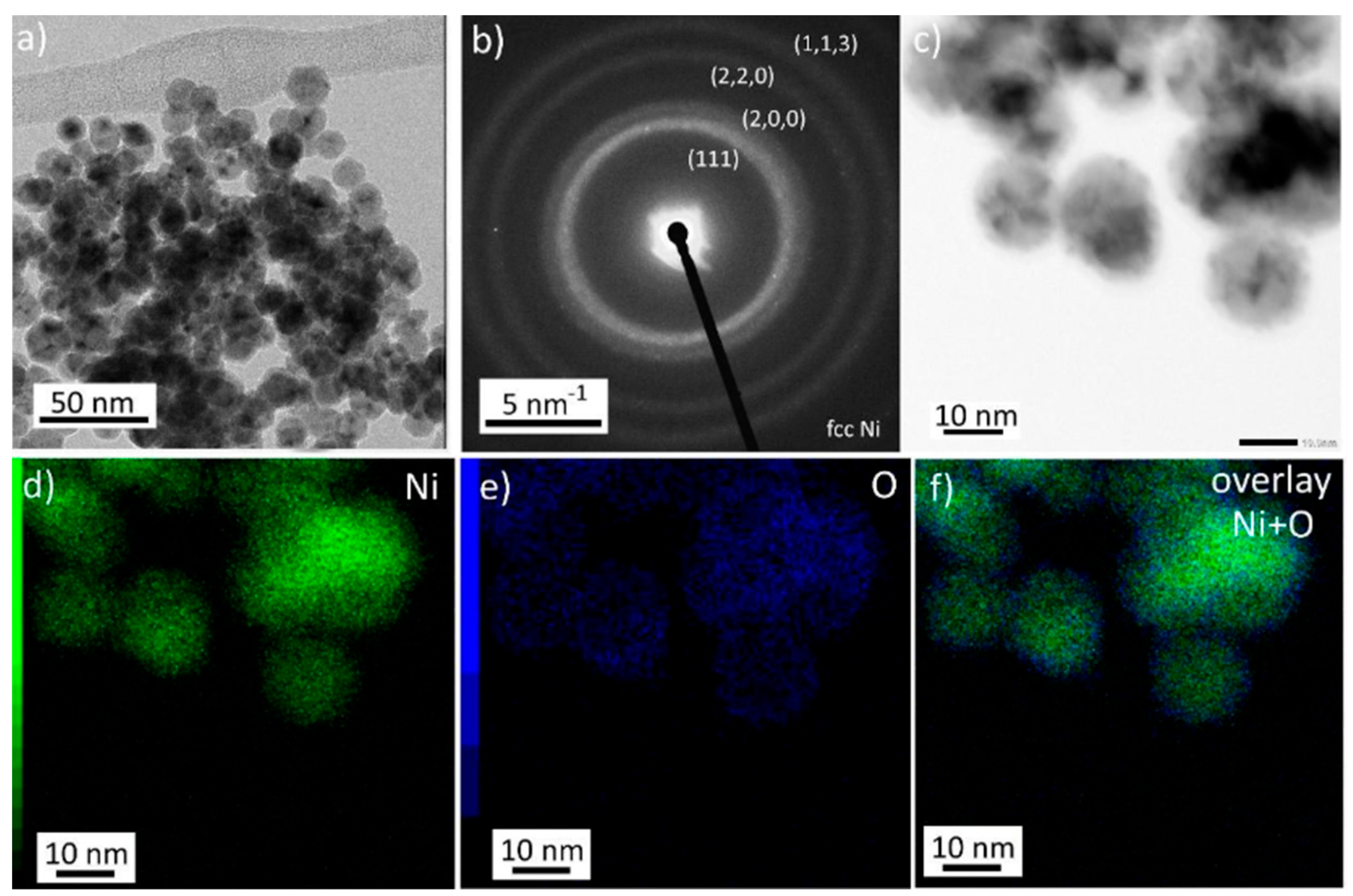
Figure 2.
Annealing of the pure Ni nanoparticles, BF STEM images. The details of the area in the white rectangle are shown under the image for each temperature. Orange arrows indicate necking of the particles, while newly formed particles with increased size are indicated by green arrows.
Figure 2.
Annealing of the pure Ni nanoparticles, BF STEM images. The details of the area in the white rectangle are shown under the image for each temperature. Orange arrows indicate necking of the particles, while newly formed particles with increased size are indicated by green arrows.
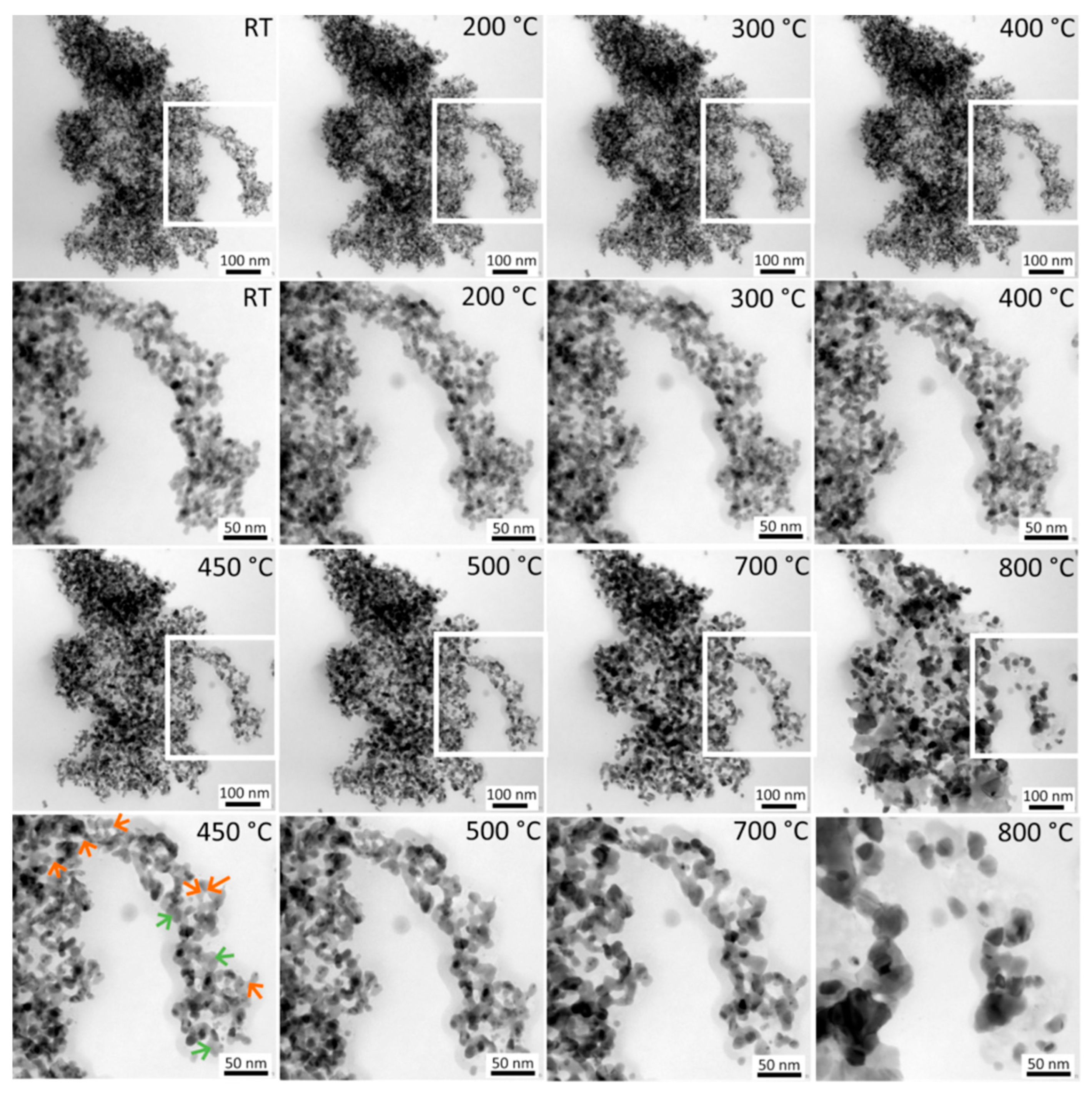
Figure 3.
TEM images of NiTi nanoparticles: a,b) TEM BF, c) STEM BF, d) STEM HAADF, e) STEM BF – image of EDS map area, f-h) EDS analysis. .
Figure 3.
TEM images of NiTi nanoparticles: a,b) TEM BF, c) STEM BF, d) STEM HAADF, e) STEM BF – image of EDS map area, f-h) EDS analysis. .
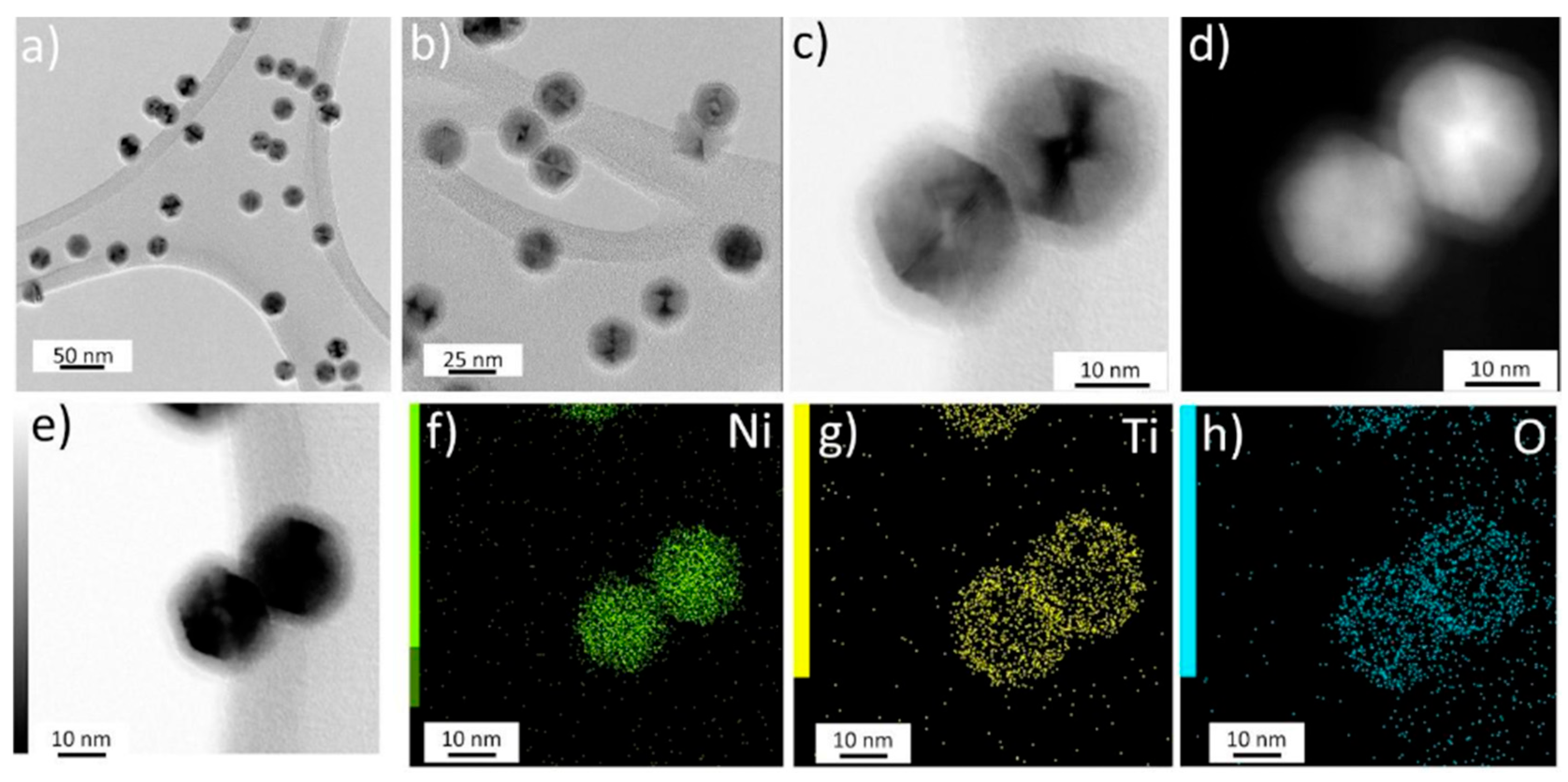
Figure 4.
a) HRTEM image of core-shell Ni@TiO2 nanoparticles: b-d) FFT images are taken from respective areas inside the blue rectangles, e) simulated diffraction patterns of fcc Ni in the corresponding orientation consistent with the FFT image in d). The core-shell structure of the particles is indicated.
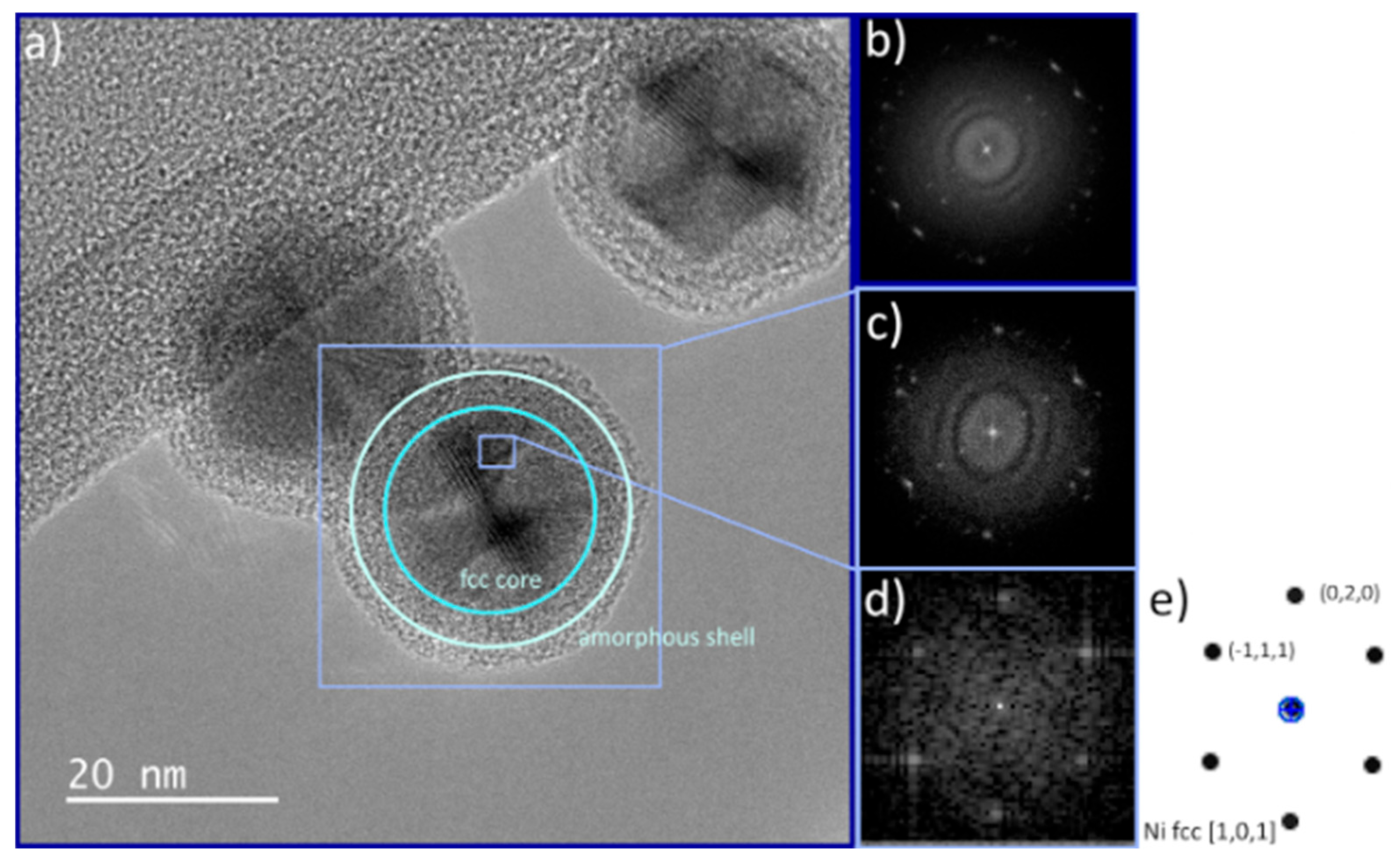
Figure 5.
Annealing of Ni@TiO2 core shell nanoparticles in the temperature range RT – 900 ˚C: a-d) and i-l) STEM BF, e-h) and m-p) STEM SE detector. .
Figure 5.
Annealing of Ni@TiO2 core shell nanoparticles in the temperature range RT – 900 ˚C: a-d) and i-l) STEM BF, e-h) and m-p) STEM SE detector. .
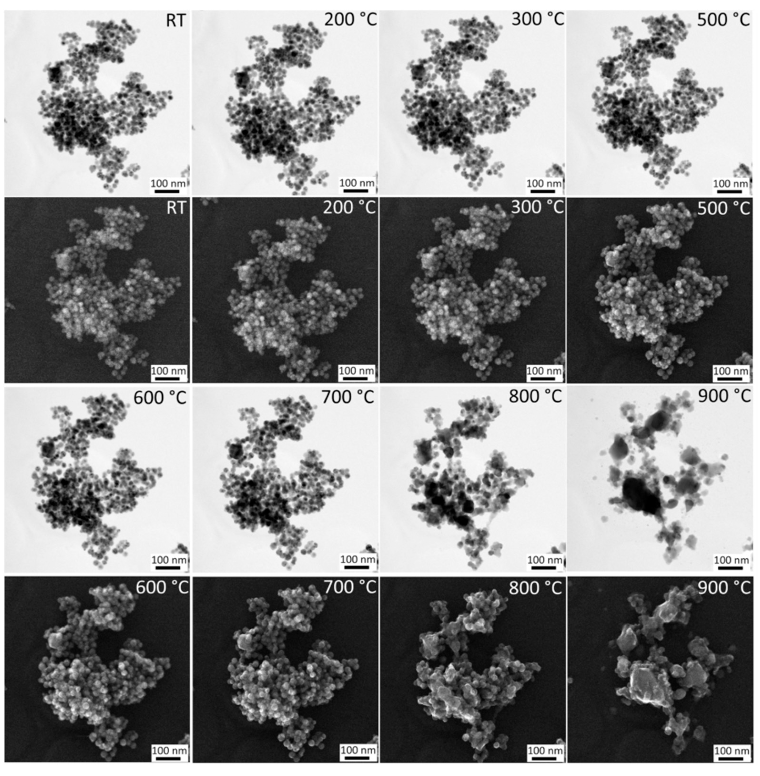
Figure 7.
a-d) HRTEM images of particles annealed between 300 and 700 °C, e) SAED diffraction pattern at 700 °C.
Figure 7.
a-d) HRTEM images of particles annealed between 300 and 700 °C, e) SAED diffraction pattern at 700 °C.
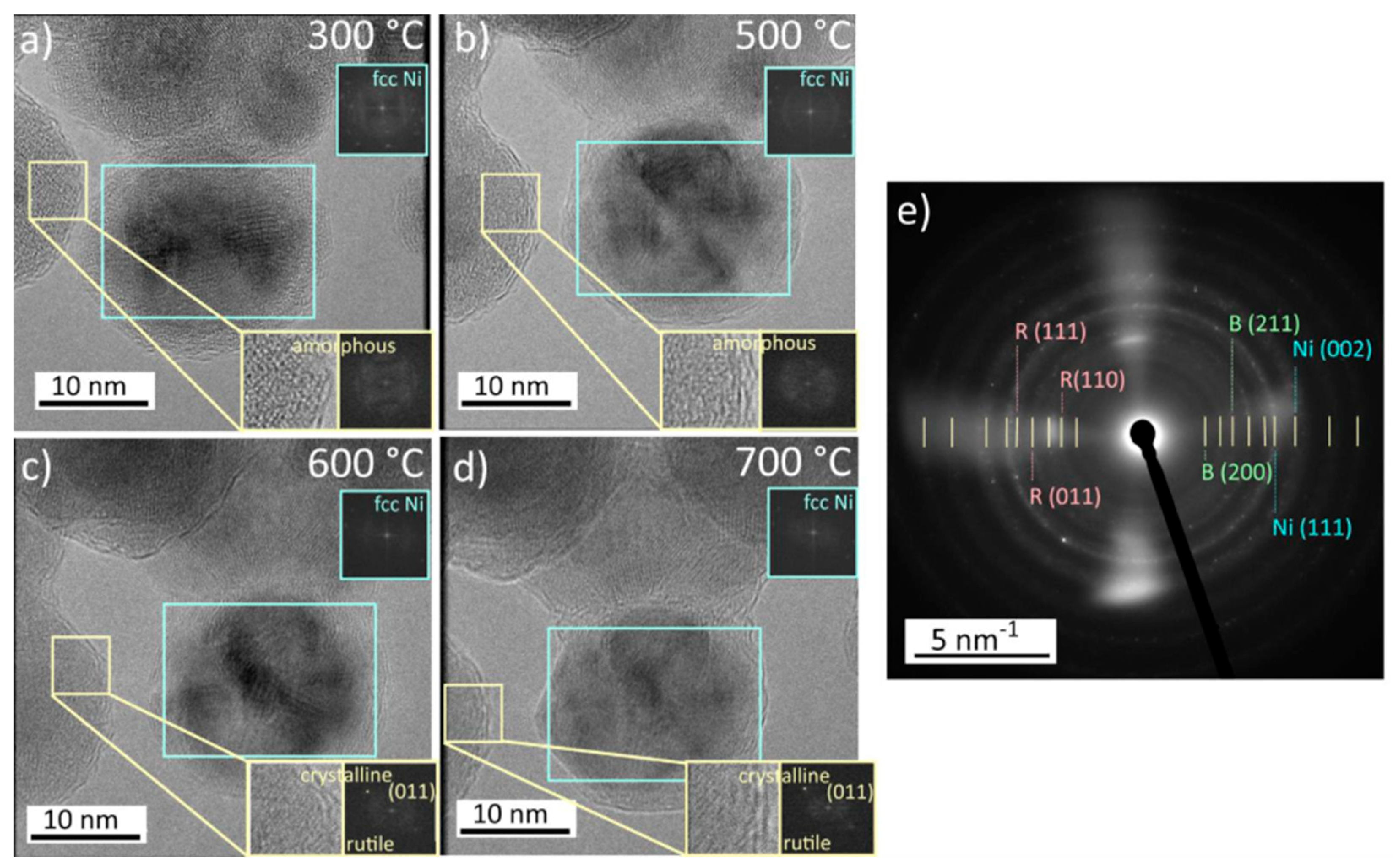
Figure 8.
HRTEM images of representative areas at temperatures between 600 and 700 °C.
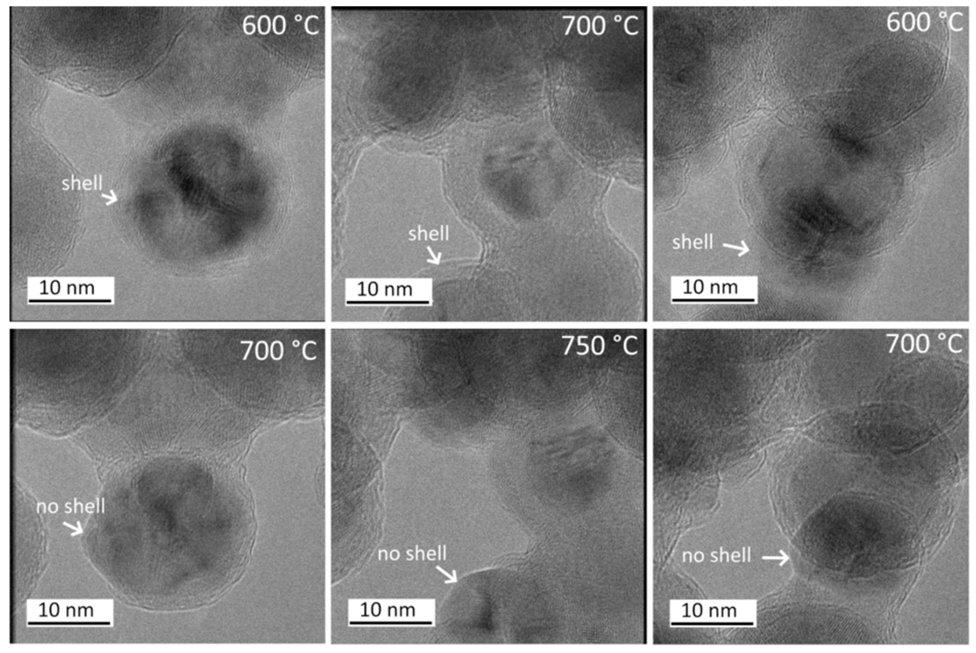
Figure 10.
Interface pressure estimated from equation (2) for average values of constants (αTiO2 = 8.4 - 11.8 *10-6 K-1, αNi = 12 - 13.5*10-6 K-1, ETiO2 = 230 - 288 GPa, BNi = 162 - 200 GPa). The stress required for the shell cracking, as estimated from the MD simulation (Figure 9), is highlighted by vertical lines (100-250 MPa).
Disclaimer/Publisher’s Note: The statements, opinions and data contained in all publications are solely those of the individual author(s) and contributor(s) and not of MDPI and/or the editor(s). MDPI and/or the editor(s) disclaim responsibility for any injury to people or property resulting from any ideas, methods, instructions or products referred to in the content. |
© 2026 by the authors. Licensee MDPI, Basel, Switzerland. This article is an open access article distributed under the terms and conditions of the Creative Commons Attribution (CC BY) license (http://creativecommons.org/licenses/by/4.0/).
Copyright: This open access article is published under a Creative Commons CC BY 4.0 license, which permit the free download, distribution, and reuse, provided that the author and preprint are cited in any reuse.


