Submitted:
19 January 2026
Posted:
19 January 2026
You are already at the latest version
Abstract
Gas exchange between soil or water surfaces and the atmosphere is one of the main sources of greenhouse gas production and absorption. Faced with global climate change and increasing atmospheric concentrations of these gases, significant scientific efforts are being made to monitor this exchange using various techniques, including closed chambers. Although relatively simple, this technique requires careful attention to several key points. Furthermore, any installation using commercial chambers is relatively expensive. Indeed, given the specific variability of gas exchange, a single chamber cannot assess all the gas exchange in the soil of a given plot. Several chambers are therefore necessary, which increases the overall cost of the installation. In our laboratory, we have built different types of chambers: portable "nomad" ultra-low-cost chambers for punctual, large-area measurement campaigns and "automatic" cost-effective chambers for long-term installations. In this article, we aim to share our experience by describing our achievements and providing a link to the complete documentation, which includes 3D and 2D plans, Gerber files for manufacturing printed circuit boards, and a parts list.
Keywords:
closed chamber
; soil and water respiration
; surface gas exchanges
; autonomous automatic chambers
1. Introduction
Unfrozen soils produce globally nearly ten times more carbon dioxide flux than the combustion of fossil fuels by all of humanity. Due to warming soil temperatures and the consequent increase in microbial activity, this production is increasing by about 0.1% per year [1]. Other Greenhouse Gases (GHGs) such as nitrous oxide N2O (nearly 300 times the warming potential of carbon dioxide), or methane CH4 (28 times the warming potential of carbon dioxide), are also produced mainly in the soil and in the aquatic environments [2,3]. There are several techniques used to monitor soil and water gas exchanges. Two main techniques are Eddy Covariance (EC) [4] and closed accumulation chambers [5]. Eddy covariance is well adapted for net flux monitoring, including soil, water, and vegetation contributions, when closed chambers are well adapted to measure the soil or water fluxes only. Eddy covariance needs to have turbulent conditions to work well when the chamber does not require it. Moreover, EC require a fast and precise gas analyzers (minimum 10 Hz operating), which are rather expensive or even not available. Consequently, during the night, Eddy covariance is often not operable as there is no wind; however, the chambers are working well. There is also a possibility of using a transparent cloche with the chambers that does not stop photosynthetic activity when the chamber is closed, allowing for the inclusion of vegetation contributions. However, as we will describe later in this paper, there are some issues with this setup. EC technique is a low-intrusive, relatively expensive technique that requires several environmental conditions and a complex setup and corrections for a quality measurement. The closed chambers technique is rather intrusive, but the simplest and much less expensive. However, as chamber measurements are very local, several chambers are necessary to monitor the overall plot activity. The installation cost then rises proportionally. Our lab has successfully entered into the DIY philosophy, significantly lowering research costs. We share our achievements with the scientific community as our chambers are already produced in our laboratory (30 pcs) for several stations, ICOS and RZA, and successfully reproduced by colleagues from other laboratories and universities. The advantages and disadvantages of DIY will be discussed. SAGE Chambers' possibilities and options will be presented.
2. Materials and Methods
2.1. Closed Accumulation Chambers Technique Principles
The closed chambers technique was described over one century ago [6] and relies on the gas accumulation or depletion over a well-delimited surface covered with a bowl. When some gases are exchanged between the concerned surface and the atmosphere (Figure 1 (a)) with corresponding flux rates F (mol*m-2*s-1), delimiting a portion of this surface S (m²) with a collar, and hermetically closing a volume V (m3) above S (Figure 1 (b)), will provoke gas concentration changes. Figure 1 schematizes the soil respiration process; it means soil oxygen uptake and soil carbon dioxide diffusion back to the atmosphere. If the carbon dioxide and oxygen fluxes, FCO2 and FO2, respectively, are assumed constant during the chamber closure, the closed chamber internal concentrations follow a simple linear law
for carbon dioxide and
for oxygen.
With and being the initial atmospheric carbon dioxide and oxygen concentration, and t being the chamber closure time. Of course, the reality is not so simple, and because the soil/water gases diffusion is not constant but depends on the surface upper-side atmosphere gas concentration. Then, in a closed chamber, as the gas concentrations change, the fluxes are not constant [7,8,9]. Consequently, gas concentrations in a closed chamber rather follow an asymptotic or exponential rise law:
CL is the equilibrium concentration (asymptotic concentration) almost reached when the chamber is closed for a long time, and k is a constant characteristic of the system. The flux is calculated making derivative of this aquation versus time at t = 0.
For short measuring time and high effluxes, both laws are very close and appear to be linear (Figure 2). However, working with short measuring times is unsafe, as at the beginning of the closure, the ideal signal is mostly disturbed by the leading-pipes' gas transit time, gas homogenization by the internal fan time, sensors’ response time, and so on. Using a linear regression and basing the slope calculations only on the first measurements is strongly subject to bias. Better results are given by longer chamber closure and asymptotic regression use.
2.1.1. Pros and Cons of the Closed Chambers Technique
This technique is relatively simple and direct. The spatial delimitation is strong, which may be considered as a default but also as a benefit depending on what the measurement target is. However, its intrusive character is consequent. The collar presence perturbs soil life (root cutting) and may provoke serious gas leaks if used in a cracking vertisol. Chamber presence causes wind and waterfall perturbations, or soil gas exchanges are strongly correlated with external conditions. When the chamber is closed, the internal atmosphere is not in the same condition as the external atmosphere conditions. Mainly, the wind is stopped, and the internal air is homogenized by a fan or other mixing device [10].
These perturbations are not always well understood and cannot always be well quantified. We should be aware of it; there is no ideal measurement technique, all approaches have advantages and limitations.
2.1.2. DIY Philosophy
Each profession has its own tools and apparatus. Scientists are no exception to the rule. We need our sensors and devices. Particularly in environmental science, as the measurement area is the whole Earth with its various climates, soil/water usage, and so on, we need a lot of measuring devices to acquire a global understanding. Our budget is not infinite; our needs are so various. The question to which we have to answer is: can we make our own device corresponding exactly to our own needs? And the answer we found was: “Yes, we can”. The conceived scientific devices are made by scientists for scientists. In 2021, an official program called TERRA FORMA brought together interdisciplinary French scientific teams who are developing a set of low-tech open-source instruments to offer new environmental measurement capabilities using a multi-messenger approach (high spatial and temporal frequency). We are part of TERRA FORMA.
As always, there are pros and cons to building your own sensors. The pros are that, simply, what you are looking for does not exist on the market, if you are making your own device, nobody will impose their design and way to work with. As is often the case, when making your devices, the necessary budget drops compared to commercial devices. Also, there is no better way to understand how “it” works than make “it” yourself. If you do so, you become totally autonomous, and you do not have to rely on commercial offers to acquire, maintain, and troubleshoot your devices. The cons are the same or so; it is not sufficient to spend money to have a device, to maintain it, or to troubleshoot it. It needs some more work…
Concerning the closed chambers, our laboratory uses two types of chambers. For a punctual campaign on large areas without any infrastructure, we are using the ultra-low-cost nomad chambers, which are described in our previous paper [11], and for which we are planning to add exploded mounting schemes. For long-installation chambers working automatically on an instrumented plot, we are using the chambers that are described in this paper. Designing these chambers requires important work. To save time for our colleagues, we are sharing all the plans (2D and 3D), parts list, PCB Gerber files, and pictures of the real chambers under Creative Commons license 4.0 (Attribution and Share alike) to allow others scientist to reproduce it https://doi.org/10.5281/zenodo.16746586.
2.2. Automatic SAGE Chambers
These chambers are designed for long-term installation, working automatically, and do not require human presence. Numerous options and configurations are possible
2.2.1. Chambers’ Design
Closed chamber design needs to respect several critical points. The geometrical shape needs to be cylindrical or, better, semi-spherical to allow good internal air homogenization without a dead space, such as corners in a cubical shape [12]. Internal chamber air should be continuously homogenized when the chamber is closed. A proper sealing between the chamber cloche and the collar is necessary, and internal pressure has to be maintained equal to the external pressure [13,14,15,16].
2.2.2. Electronic and Mechanical Construction of SAGE Chambers
The target was to build a durable closed chamber compatible with ICOS requirements [17] that can be reproduced by anyone, without any specialized electronic knowledge or machining skills. Everyone who can weld a through-hole resistor or drill and tape a hole in an aluminum part can build that chamber. The second target was to use as many commercial parts as possible, such as a stainless-steel salad bowl for a chamber cloche, and sensors or electronic devices mounted in widely available commercial modules to avoid unnecessary work, cost rise, and to allow a very simple replacement process. The third goal was to make a chamber that can be used for a wide range of measurement needs: soil, water, opaque cloche, or transparent one, with several options such as anti-vegetation pinch grids. Special care was taken for the chamber installation and maintenance, or for troubleshooting ease.
All electronics modules are wildly-disponible and require only a connector (female pin header or a strap) soldering on the main PCB (Figure 3) or under-cloche PCB. Besides the modules’ connectors, there are also wire connectors, a few diodes, resistors, and some exclusion network resistors used to form a simple voltage divider. All parts are through-hole mounting, not surface mounting, and do not require any special tools. PCB can be ordered online. It is only two layers, which makes it rather low-cost with a comfortable pin pitch to make soldering and wire mounting easy. Main used electronic modules:
- The used microcontroller is a Mega Pro Mini programmable using C and C++ under Arduino IDE, fully compatible with Arduino Mega 2560.
- To be able to use a 24V power line, there are two dc-dc step-down modules. The first module, used only if a 24V power line is actually used, delivers 12V for the motor and, eventually, some sensors, such as the soil water content probe, through a Solid-State Relay (SSR) to be able to cut down the sensors' power line and to save some energy when they are not used. This DC-DC is replaced by a jumper if the used power line is a 12V. The second DC-DC step-down delivers 5V to recharge an internal security battery, to power the microcontroller and all other modules, including the sensors, through another SSR.
- The air homogenization fan is Pule Wide Modulation (PWM) controlled, with an embedded tachometer (4-wire fan) to precisely control its speed of rotation, which is checked and recorded. For a transparent cloche, this fan is also transparent. PWM control is useful for changing fan rotation speed and adapting it to external wind conditions or other factors. This part of the measurement condition adaptations for CO2 efflux is under test and will be described later. For evaporation measurement, because a closed chamber is also able to measure surface evaporation, the wind influence was already corrected and described [10]
- A PWM generator piloted by the microcontroller is implemented on the main board to achieve Fan speed control.
- The embedded OLED display allows for the showing of some info when required. The keys on the OLED module allow interaction with the microcontroller and, consequently, allow several pages and options to be displayed. This display should be cleared when not used to save some energy. The embedded microcontroller is able to manage it.
- Inside the chamber main box, there is an internal battery along with an Uninterrupted Power Supply (UPS). When the main power is available, the battery is recharged. This battery serves to power the microcontroller and the SD card module in case of a main power shortage, allowing it to stop any actions waiting for the power to be restored. It is a security device preventing SD card corruption held directly by an SD card module, deported in an easy-to-access holder plugged with a ribbon cable to the SD module.
- Two LC filters to limit the DC-DC step-down module and motor noise.
- A Real Time Clock module (DS3231-based) is used to hold the current date and time.
- Two delayed switches, along with a motor pilot (DRV8871 H Bridge-based), help to open or close the chamber when triggered by the microcontroller.
- A logic level shift is used between the microcontroller (5V logic level) and the Luminox sensor (3.3V logic level), even if it is not strictly necessary, as Luminox is 5V logic level tolerant and the microcontroller “understands” 3.3V logic level UART inputs. This logic level shifter is also used to reserve one I²C line from the multiplexer (see further text) for a 3.3V logic level.
- A communication module allows the use of RS-485 or another module, RS-422, for long-distance communication. There is also a reserved place and a connector for the LoRa WAN module. However, we kept in mind that LoRa allows a long-range radio communication of low-density data, so the chambers’ raw data cannot be transmitted. However, the internally computed fluxes can be.
- An I²C line multiplexer is added to allow for multiple I²C devices to be used and to add several optional I²C devices without worrying about possible I²C address conflicts. Additionally, most I²C communication-based modules typically have their own pull-up resistors. Then, if there are too many modules on the same line, the resulting Pull-up resistors are too weak. In other words, it is necessary to separate the I²C modules even if there is no address conflict.
- Because the under-cloche sensors are I²C and because this communication bus is not designed for long wires, A switch and connectors are placed on the main board to implement an optional I²C expander module based on the PB2B715 chip. This module allows the use of longer wires between the main board and the under-cloche board with sensors. However, with the high-quality wires we are using, our chambers do not require the I²C expander use.
- As the optional GPS uses the SERIAL0 UART line of the microcontroller, when the GPS is used, and the microcontroller is booting (may be booted by the watchdog), a blockage may occur. To solve this problem, a magnetic isolator based on ADUM1201 is inserted on the SERIAL0 line between the microcontroller and the GPS connector. This isolator is powered by the microcontroller, and when booting, the microcontroller is not powering it, setting the SERIAL0 line as disconnected. There is no more blocking possibility.
- Finally, a DIP switch block (4 Pin) is used for address indication, allowing 16 hard-coded unique addresses. Indeed, each chamber has its own address.
Mechanical parts are made as often as possible from commercial parts. There is a need to drill these parts, sometimes tap them, paint them, and so on. Other parts are custom-made and can be ordered online, providing the 2D and 3D drawings. We are including several exploded mounting schemes and descriptions to facilitate assembly, along with the 2D and 3D parts’ plans (Figure 4).
2.2.3. Pricing
The price depends on where the parts are bought or made. For reference, a chamber made in France from electronic parts bought in an Asian online store and the custom-made parts made in Maghreb (North Africa) is about 2000€, which is about 1/3 of the commercial chambers’ price.
2.2.4. Options and Possible Configurations
SAGE automatic chambers are designed for various installation configurations and needs.
-
Serial or autonomous configuration.The same chamber can be used, as usual, in a network of several chambers connected to a pneumatic multiplexer and then to a single air analyzer (Figure 5), which is referred to as the “serial” configuration. This configuration is necessary for gas measurements such as nitrous oxide because an analyzer able to measure such small concentrations with such good precision is big and expensive. In other words, it is not realistic to equip each chamber with this kind of analyzer. Chambers are then connected to a pneumatic multiplexer, switching the pumped air sequentially from each chamber, injected into the analyzer, and driven back to the concerned chamber. This installation requires an external piloting, which is usually done by a datalogger that pilots the multiplexer and chambers, and reads data from the gas analyzer. SAGE automatic chambers have the possibility to attach two pipes for air pumping (IN and OUT) and use an RS-485 or RS-422 (both modules can be mounted on the main PCB) to communicate with an external datalogger using a simple protocol.Another, much simpler configuration, so-called “autonomous” (Figure 6), used for the gases that do not require a unique analyzer, lets analyze gases directly under each chamber’s cloche without gas leading pipes, a pneumatic multiplexer, and a unique, expensive analyzer. Automatic SAGE chambers equipped with opaque cloche can use embedded sensors for CO2 measurement (SCD30 from Sensirion), for O2 measurement (Luminox from SST Sensing), for CH4 measurement (TGS2611 from Figaro), for NH3 and H2S (SC05-NH23 and SC05-H2S from Shenzhen Shenchen Technology Co.). All these gases can be measured simultaneously; however, H2S presence can greatly affect CH4 sensor readings. Additionally, each CH4 sensor must be individually calibrated and corrected for air temperature and air moisture, which is a rather complex process [18]. Air constants such as air temperature, air moisture, and air pressure are sensed by the BME280 from Bosch. SAGE chambers equipped with transparent cloche can embed BME280 and CO2, O2, and CH4 sensors only, as under a transparent cloche, the PCB should be small to avoid shadowing enclosed vegetation. However, for any special needs, everything can be adapted. Used CO2 and O2 sensors are the same as for our nomad chambers and are already described in our previous paper [11] and will not be compared here. We will only recall that obviously, the small, cheap sensors are not as accurate as a big, expensive analyzer. There is no miracle. However, small sensors can be based on the same technology, such as Non-Dispersive Infrared (NDIR), and their accuracy is often limited in terms of the absolute value. For the closed chambers, the value flux calculations are based on measured concentration variations, not on the absolute value. Also, using leading air pipes with closed chambers induces some errors. In case of any leak, errors can be important. And the leak occurs all the more, there are numerous pneumatic connections between chambers and multiplexer, between multiplexer and analyzer, or between analyzer and the pump.Any possible leak in a connection is potentially disastrous, as the pressure is lower inside the pumped air tubes and higher inside the driven back air tubes compared to the atmospheric pressure. Inside the multiplexer, there is also a set of solenoid valves, which are rather sensible component that may leak and break down. The pump itself may also leak and break down. The installation with embedded sensors of the lowest accuracy may, all things considered, prove to be more accurate and more reliable.Another benefit of the embedded sensors is the possibility of simultaneous chamber measurement, allowing us to separate spatial variability from temporal variability. Indeed, with the unique analyzer installation, there is no alternative but to perform sequential measurements. In this case, the measurements coming from different chambers may vary because of chamber location (spatial variability), but also because of the chamber measurement period during the day (temporal variability). When the sensors are embedded under the cloche of each chamber, nothing prevents us from measuring at the same time. Also, each chamber is equipped with 32Gb internal memory, allowing to log acquired data. If chamber closure is triggered every three hours for ten minutes, 32Gb provide enough memory for 2000 years of measurements, which is rather comfortable. Data saved in the internal memory can be retrieved by RS-485 or RS-422, whichever is used, by direct USB connection, or by physically removing the SD card, which is the fastest way. This SD card (micro-SD card in fact) is accessible without chamber dismounting but deported into a waterproof SD card holder.The embedded memory may serve to save acquired data, but also to save a log file that includes any information helping to identify dysfunction, if any, and the configuration file.It is a matter of internal soft programming, which is open to each user. In our laboratory, we chose to check and record results for each sensor at each microcontroller boot or wakeup. Any action required is logged and the result saved. If errors are constated adapted checks are performed and results saved. This log file is very useful for troubleshooting.
-
External sensors.Auxiliary measurements, such as soil/water temperature or soil water content, are possible using several sensors. We are always adding soil/water temperature sensors based on the DS18B20 chip, soil water content when the chamber is used on the soil surface, and based on FDR technology with analog output. Other sensors can be added, one analog and a few using I²C communication on six free I²C lines from the multiplexer (one of the lines is a 3.3V logical level). Free I²C lines allow adding a few Analog-to-Digital Converters (ADC), I²C to UART converters for serial communications, and so on, expanding evolution possibilities. An optional GPS (TTL communication) is foreseen, and its connector is optionally placed on the main box. The microcontroller manages it and records the chamber position when a measuring cycle is triggered. This possibility may be interesting when the chamber is freely floating on a lake. For additional sensors, a connector or cable gland should be added.
-
Internal data logger and battery-powered operations.As the chambers can be autonomous for gas analysis, the step to make them autonomous for functioning is relatively small. There is everything onboard, inside each chamber, to pilot its own actions according to the configuration file with the help of an embedded internal RTC. If a 7S3P Li-ion battery made with 4000mAh capacity 18650 elements is attached, 6 weeks of the chamber’s functioning is possible (10 minutes cycle every 3 hours) if the chamber enters deep sleep mode between each cycle. This mode is possible as the internal RTC has its own little rechargeable battery that can power it for years without recharging, and as this RTC can wake up the microcontroller at a programmed date.If an individual solar panel 40cmx33cm is added on the top of the chamber, the limitation of the chamber battery usage is greatly increased, but the limits are not yet known, as our setup was always working correctly during this year. It should be tested with lower solar radiation and lower temperatures that may affect Li-ion battery performance, but locally, as these conditions are specific to each location. When the used solar panel is sufficient for southern France, it may not be sufficient for Greenland.Usual scheduling imposes a periodic cycle triggered every X time. However, we can set SEGE chambers to trigger a cycle randomly with a minimum and maximum waiting time. In this case, if, in spite of this, we want to keep chamber closure all at the same time without any external data logger, we can set one chamber as the master, triggering the other chamber closure. But this is purely a programming matter, not a hardware problem, except for the need to connect all the chambers with a communication line.
-
Anti-pinch grids.For chamber installation on an agricultural plot sown, for example, with winter wheat or rapeseed. There is always a possibility that a straw or other vegetation material gets pinched during chamber closure. In this case, measurements are not valid as the chamber airtightness is compromised. To prevent this kind of situation, we can temporarily attach the anti-pinch grids (Figure 7).
-
Opaque or transparent cloche.An opaque cloche is used when only the soil or water, gas production, or sink is studied. To include photosynthetic activity, a transparent cloche should be used. We are using a PMMA cloche for this purpose, along with a small under-cloche PCB. A transparent cloche is never completely transparent; the chamber base is not transparent, and the collar, even if made from PMMA, is neither totally transparent. A condensation may also be observed on the interior closed cloche [19], which is affecting the solar radiation transmission. All these components stop some percentage of solar radiation. When a transparent cloche is used, the air temperature trapped under this cloche during the measurement cycle can have its temperature quickly rise; typically, 15°C during 10 minutes of closure under the southern French sun. For this reason, air temperature should be checked, and the measurement cycle should end if the air temperature rise is judged too high. Also, as the photosynthetic activity depends on Photosynthetically Active Radiation (PAR), which can change during the measurement cycle due to the cloud presence, a PAR sensor should be added and the corresponding data recorded. The transparent-cloche-equipped chamber should be oriented with the under-cloche PCB on the north side, and to prevent an eventual solar panel from shadowing the measurement zone.An opaque cloche is used when studying only soil or water, gas production/sink. To include photosynthetic activity, a transparent cloche is required. For this purpose, we use a PMMA cloche with a small printed circuit board holding sensors positioned beneath it, along with a transparent fan. A transparent cloche is never completely transparent: the base of the chamber is neither, and the collar, even if made of PMMA, is not entirely transparent. Condensation can also form inside the closed cloche [19], affecting the transmission of solar radiation. All these components block some of the solar radiation. When using a transparent cloche, the temperature of the air trapped beneath it during the measurement cycle may rise rapidly, typically by 15°C in 10 minutes under the southern French sun. Therefore, it is important to monitor the air temperature and interrupt the measurement cycle if the temperature rise is deemed excessive. Furthermore, since photosynthetic activity depends on photosynthetically active radiation (PAR), which can vary during the measurement cycle due to cloud cover, it is necessary to add a PAR sensor and record the corresponding data. The chamber equipped with a transparent cloche must be oriented so that the printed circuit board under-cloche faces north; this orientation is necessary to prevent an eventual solar panel from casting a shadow on the measurement area.
-
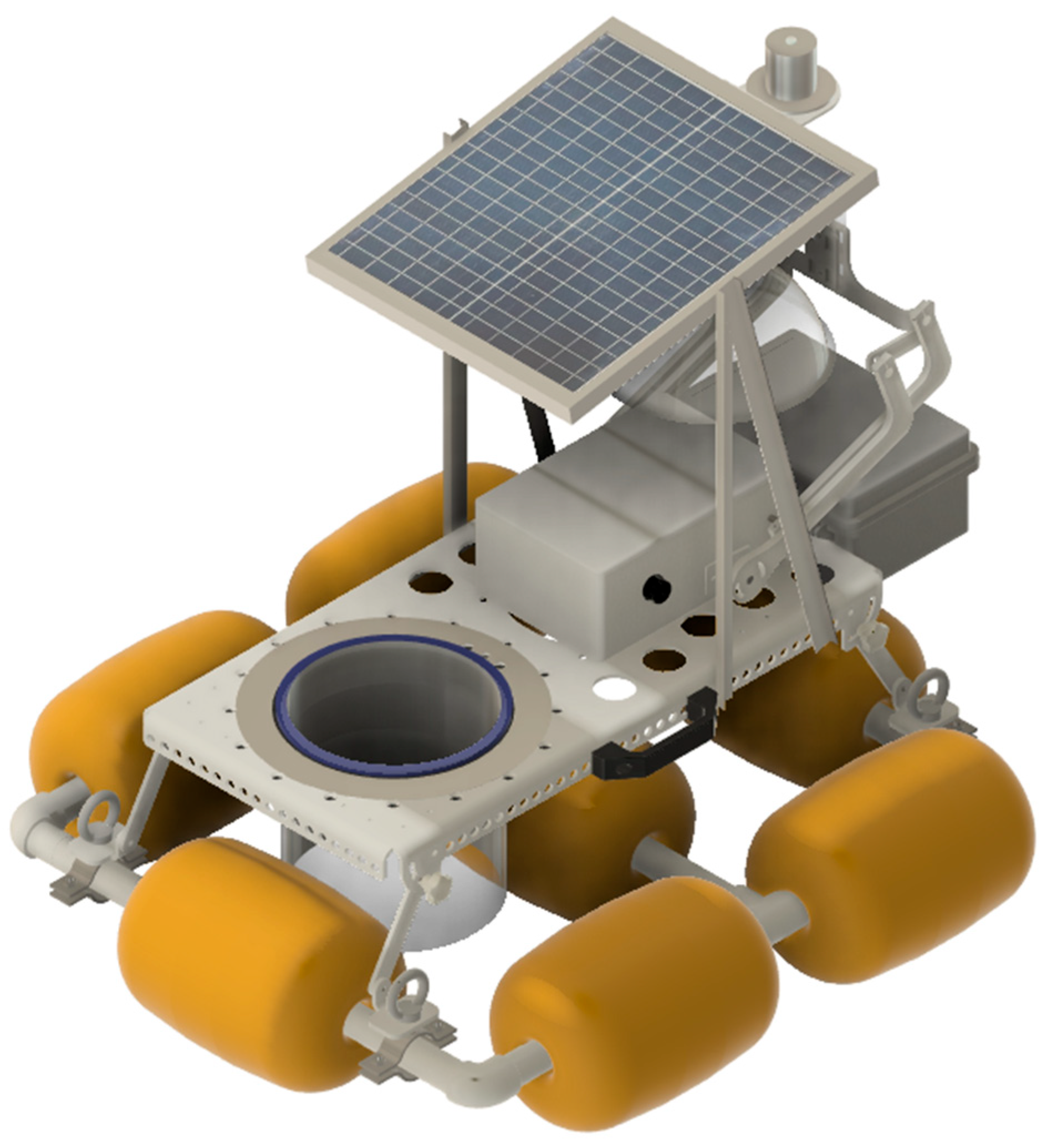
Soil or water monitoring.To our knowledge, no commercial chamber is specifically designed for use on the water surface. This is certainly a deficiency, as water also exchanges gases with the atmosphere, and until now, scientists have had to improvise to obtain the relevant measurements.For monitoring water exchange with the atmosphere, waterwings made of standard PVC tubing and fittings, as well as fishing buoys, can be added (Figure 8). A standard chamber, usually equipped with a battery, is then attached to these waterwings. The stainless-steel collar is replaced with a PVC or PMMA collar. Figure 8 shows a SAGE chamber with a transparent cloche equipped with a PAR sensor mounted on the solar panel and a battery housed in a waterproof casing at the rear of the chamber.The described floating setup is suitable for relatively calm water surfaces, but cannot be used on oceans or rough waters.
3. Results
3.1. Durability and Adaptability
Resulting chambers are relatively easy to mount, install, and use. For durability check purposes, one chamber was set to execute a short cycle every three minutes for over one month. Typically, the number of closures and openings would correspond to a five-year functioning. No specific tear or usure was observed. Some chambers have been installed in a field for over one year, displaying very simple maintenance needs. We can consider these chambers as durable and relatively inexpensive. However, the main advantage resides in the fact that all remain adaptable to specific needs and may be completed or changed. Additional sensors can be added, the embedded software can be changed, and the chambers’ design can be modified.
3.2. Maintenance and Troubleshooting
The main electronic board is composed of widely available modules that can be purchased and changed if ever needed. A log file greatly simplifies any debugging process, and there is no particular knowledge or skills needed to find which module is faulty or to change it. Up to now, the only module that has to be changed was the burned DC-DC adaptor due to our incorrect polarity battery connection.
The embedded sensors have a restraint calibration possibility. The SCD30 sensor can be calibrated to change its baseline; however, this does not even affect the chamber measurements. Methane sensors need a sensor-specific calibration, and oxygen, like other sensors, is not calibratable. Due to their low-cost, we suggesting then to change it every two years.
3.3. Versatility and Adaptability
Water surface gas exchanges are not negligible; however, no commercial chambers are adapted to dedicated measurements. With the waterwings added to the SAGE chambers, these measurements become accessible by an automatic closed chamber.
Battery-powered chambers, with or without a solar panel, being totally autonomous, allow for measuring soil or water efflux without any specific infrastructure. Data are stored in the chambers and can be easily retrieved. All chambers can be stand-alone.
When working on agricultural plots, the chambers are often subject to vegetation-caused failures due to the air tightness lost when the vegetation is pinched by the closing cloche. The anti-pinch grids are highly effective and make reliable chamber measurements.
The main board includes several communication lines that allow the addition of other circuits and devices, such as analog-to-digital converters (ADC) or digital-to-analog converters (DAC), serial UART lines, light sensors, and so on. As the embedded microcontroller can be easily programmed, even external gas analyzers can be interfaced if needed.
4. Discussion
It is challenging to report every possible configuration and all the available options, as existing options can be combined and new options can be added. It is an intrinsic advantage of a DIY achievement; the main limiting factor is our imagination. These open-access chambers may only benefit from being shared.
The described chambers can be used “as is” for various needs or can be completed and even modified for other needs. This is the advantage of “self-made” devices with open access resources.
SAGE chambers have been deployed on an ICOS site operating continuously over an extended period, demonstrating their robustness and operating reliability. They are currently deployed RZA sites.
We are currently working to make SAGE chambers compatible with Li-COR systems, both older (analog) and newer (digital) generations. This would allow SAGE chambers to complement existing Li-COR installations, simply increasing the number of chambers that can be used. Moreover, this possibility is allowed, and Li-COR distributes the necessary documentation. To complete the serial configuration installation, we will also propose our open-access pneumatic multiplexers.
5. Conclusions
In this paper, we presented the SAGE automatic closed chambers, an open-access and cost-effective system designed for long-term monitoring of soil and water surface–atmosphere gas exchanges. Rather than introducing new theoretical developments, this work focuses on practical design choices, reproducibility, and field-oriented implementation of an automatic chamber system compatible with ICOS requirements.
The proposed design combines mechanical simplicity, modular electronics, and a flexible software architecture, enabling both serial configurations using external gas analyzers and fully autonomous configurations based on integrated, low-cost sensors. Particular attention has been paid to the key methodological constraints of closed-chamber measurements, including air mixing, pressure balancing, chamber geometry, and operational robustness during prolonged field deployment.
By relying on widely available commercial components and by sharing all mechanical drawings, electronic schematics, firmware elements, and assembly documentation under a Creative Commons license, the SAGE chambers lower the barrier to deploying dense chamber networks. Beyond soil applications, the system also enables gas exchange measurements at the water–atmosphere interface, addressing a current limitation of most commercial chamber solutions.
Overall, the SAGE chambers illustrate how open-hardware approaches can complement existing commercial systems and contribute to more accessible, scalable, and transparent greenhouse gas monitoring infrastructures. Future work will focus on extended interoperability with reference commercial systems and on the continued development of the open-access system around SAGE chambers.
Author Contributions
Conceptualization, B.Z.; methodology, B.Z.; software, B.Z.; validation, B.Z., and V.B.; formal analysis, B.Z. and V.B.; investigation, B.Z and V.B.; resources, B.Z.; data curation, B.Z.; writing—original draft preparation, B.Z.; writing—review and editing, B.Z and V.B.; visualization, B.Z and V.B.; supervision, B.Z.; project administration, B.Z.; funding acquisition, B.Z and V.B. All authors have read and agreed to the published version of the manuscript.
Funding
The development of these devices is mainly financed by the INSU (National Institute of Universe Sciences) through the AAP IIT and TGIR ICOS, by Terra Forma, the National aid managed by the National Research Agency under the future investment program integrated into France 2030, bearing the reference ANR-21-ESRE-0014, by Anna Zawilski and by the Regional Space Observatory supported by the laboratory CESBIO (Center for Space Studies of the Biosphere).
Acknowledgements
We would like to thank Laura Leal, our manager, who handles thousands of small orders. We also thank Dalibor Pejicic of CADENAS for his invaluable help in finding the 3D models used to create the exploded views.
Conflicts of Interest
The authors declare no conflicts of interest
Abbreviations
The following abbreviations are used in this manuscript:
| GHGs | Greenhouse gases |
| EC | Eddy Covariance |
| ICOS | Integrated carbon observation system |
| RZA | Réseau des zones atelier |
| SSR | Soli state relay |
| PWM | Pulse width modulation |
| UPS | Uninterruptible power supply |
| SD | Secure digital |
| TTL | Transistor-Transistor Logic |
| UART | Universal asynchronous receiver transmitter |
| ADC | Analog to digital converter |
| DAC | Digital to analog converter |
| PAR | Photosynthetically active radiation |
| NDIR | Non-Dispersive Infrared |
References
- Bond-Lamberty, B.; Thomson, A. Temperature-associated increases in the global soil respiration record. Nature 2010, 464, 579–582. [Google Scholar] [CrossRef]
- Zhu, G.; Shi, H.; Zhong, L.; et al. Nitrous oxide sources, mechanisms and mitigation. Nat Rev Earth Environ 2025, 6, 574–592. [Google Scholar] [CrossRef]
- Günthel, M.; Donis, D.; Kirillin, G.; et al. Contribution of oxic methane production to surface methane emission in lakes and its global importance. Nat Commun 2019, 10, 5497. [Google Scholar] [CrossRef] [PubMed]
- Burba, G. Eddy Covariance Method for Scientific, Regulatory, and Commercial Applications. LI-COR Biosciences 2022. Available online: https://www.licor.com/products/eddy-covariance/ec-book.
- Maier, M.; Weber, T.K.D.; Fiedler, J.; Fuß, R.; Glatzel, S.; Huth, V.; Jordan, S.; Jurasinski, G.; Kutzbach, L.; Schäfer, K.; Weymann, D.; Hagemann, U. Introduction of a guideline for measurements of greenhouse gas fluxes from soils using non-steady-state chambers. Journal of Plant Nutrition and Soil Science 2022, 185, 447–461. [Google Scholar] [CrossRef]
- Bornemann, F. Kohlensaure und Pflanzenwachstum. Mitt. Dtsch. Landwirtsch-Ges. 1920, 35–363. [Google Scholar]
- Livingston, G.P.; Hutchinson, G.L.; Spartalian, K. Diffusion theory improves chamber-based measurements of trace gas emissions. Geophys. Res. Lett. 2005, 32, L24817. [Google Scholar] [CrossRef]
- Kutzbach, L.; Schneider, J.; Sachs, T.; Giebels, M.; Nykänen, H.; Shurpali, N.J.; Martikainen, P.J.; Alm, J.; Wilmking, M. CO2 flux determination by closed-chamber methods can be seriously biased by inappropriate application of linear regression. Biogeosciences 2007, 4, 1005–1025. [Google Scholar] [CrossRef]
- Silva, J.P.; Lasso, A.; Lubberding, H.J.; Peña, M.R.; Gijzen, H.J. Biases in greenhouse gases static chambers measurements in stabilization ponds: Comparison of flux estimation using linear and non-linear models. Atmospheric Environment 2015, 109, 130–138. [Google Scholar] [CrossRef]
- Zawilski, B.M. : Wind speed influences corrected Autocalibrated Soil Evapo-respiration Chamber (ASERC) evaporation measures. Geosci. Instrum. Method. Data Syst. 2022, 11, 163–182. [Google Scholar] [CrossRef]
- Zawilski, B. M.; Bustillo, V. Ultra-low-cost manual soil respiration chamber. Geosci. Instrum. Method. Data Syst. 2024, 13, 51–62. [Google Scholar] [CrossRef]
- Livingston, G.P.; Hutchinson, G.L. Enclosure-based measurement of trace gas exchange: applications and sources of error. In Biogenic trace gases: measuring emissions from soil and water; Matson, P.A., Harris, R.C., Eds.; Blackwell Science Ltd.: Oxford, UK., 1995; pp. 14–51. [Google Scholar]
- Koskinen, M.; Minkkinen, K.; Ojanen, P.; Kämäräinen, M.; Laurila, T.; Lohila, A. Measurements of CO2 exchange with an automated chamber system throughout the year: challenges in measuring night-time respiration on porous peat soil. Biogeosciences 2014, 11-2, 347–363. [Google Scholar] [CrossRef]
- Parkin, T.B.; Venterea, R.T. Chamber-Based Trace Gas Flux Measurements. IN Sampling Protocols Chapter 3, R.F. Follett, USA, 2010, pp. 3-1 to 3-39. Available online: https://www.ars.usda.gov/ARSUserFiles/np212/chapter%203.%20gracenet%20Trace%20Gas%20Sampling%20protocols.pdf.
- Christiansen, J. R.; Korhonen, J. F. J.; Juszczak, R.; Giebels, M.; Pihlatie, M. Assessing the effects of chamber placement, manual sampling and headspace mixing on CH4 fluxes in a laboratory experiment. Plant and Soil 2011, 343, 171–85. [Google Scholar] [CrossRef]
- de Klein, C.A.M.; Harvey, M.; Clough, T.J.; Petersen, S.O.; Chadwick, D.R.; Venterea, R.T. Global Research Alliance N2O chamber methodology guidelines: Introduction, with health and safety considerations. J. Environ. Qual. 2020, 49, 1073–1080. [Google Scholar] [CrossRef]
- Pavelka, M.; Acosta, M.; Kiese, R.; Altimir, N.; Brümmer, C.; Crill, P. M.; Darenová, E.; Fuß, R.; Gielen, B.; Graf, A.; Klemedtsson, L.; Lohila, A.; Longdoz, B.; Lindroth, A.; Nilsson, M. B.; Jiménez, S.M.; Merbold, L.; Montagnani, L.; Peichl, M.; Pihlatie, M.; Pumpanen, J.; Ortiz, P.S.; Silvennoinen, H.; Skiba, U.M.; Vestin, P.; Weslien, P.; Janous, D.; Kutsch, W.L. Standardisation of chamber technique for CO2, N2O and CH4 fluxes measurements from terrestrial ecosystems. International Agrophysics 2018, 32, 569–587. [Google Scholar] [CrossRef]
- Bastviken, D.; Nygren, J.; Schenk, J.; Parellada Massana, R.; Duc, N.T. Technical note: Facilitating the use of low-cost methane CH4 sensors. Biogeosciences 2020, 17-13, 3659–3667. [Google Scholar] [CrossRef]
- Zhao, P; Hammerle, A; Zeeman, M; Wohlfahrt, G. On the calculation of daytime CO2 fluxes measured by automated closed transparent chambers. Agricultural and Forest Meteorology 2018, 263, 267–275. [Google Scholar] [CrossRef] [PubMed]
Figure 1.
(a) Natural soil respiration. (b) Soil surface delimited by a collar, with the above volume closed by a chamber cloche (“lid”).
Figure 1.
(a) Natural soil respiration. (b) Soil surface delimited by a collar, with the above volume closed by a chamber cloche (“lid”).
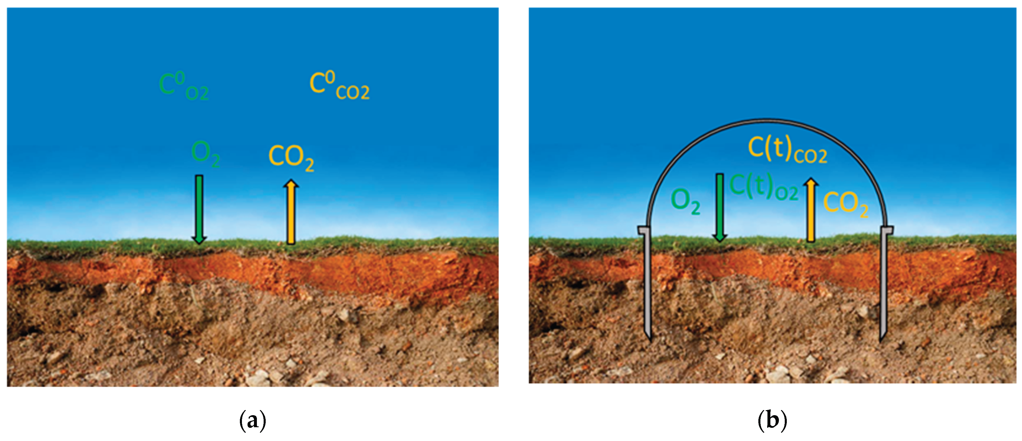
Figure 2.
(a) Measuring during a short closure. (b) The same measurements were done during a longer closure.
Figure 2.
(a) Measuring during a short closure. (b) The same measurements were done during a longer closure.
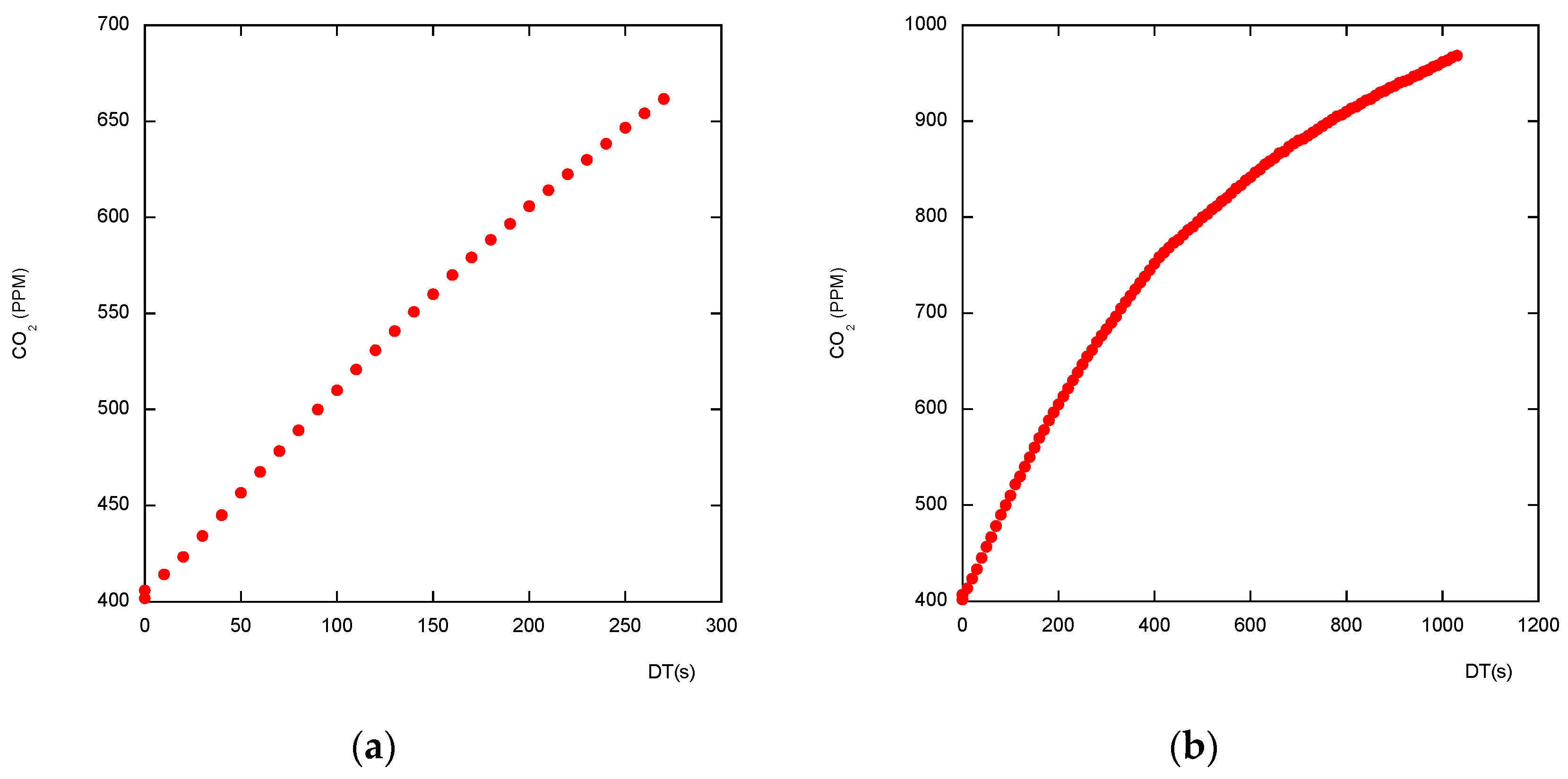
Figure 3.
Main PCB version 03/25.
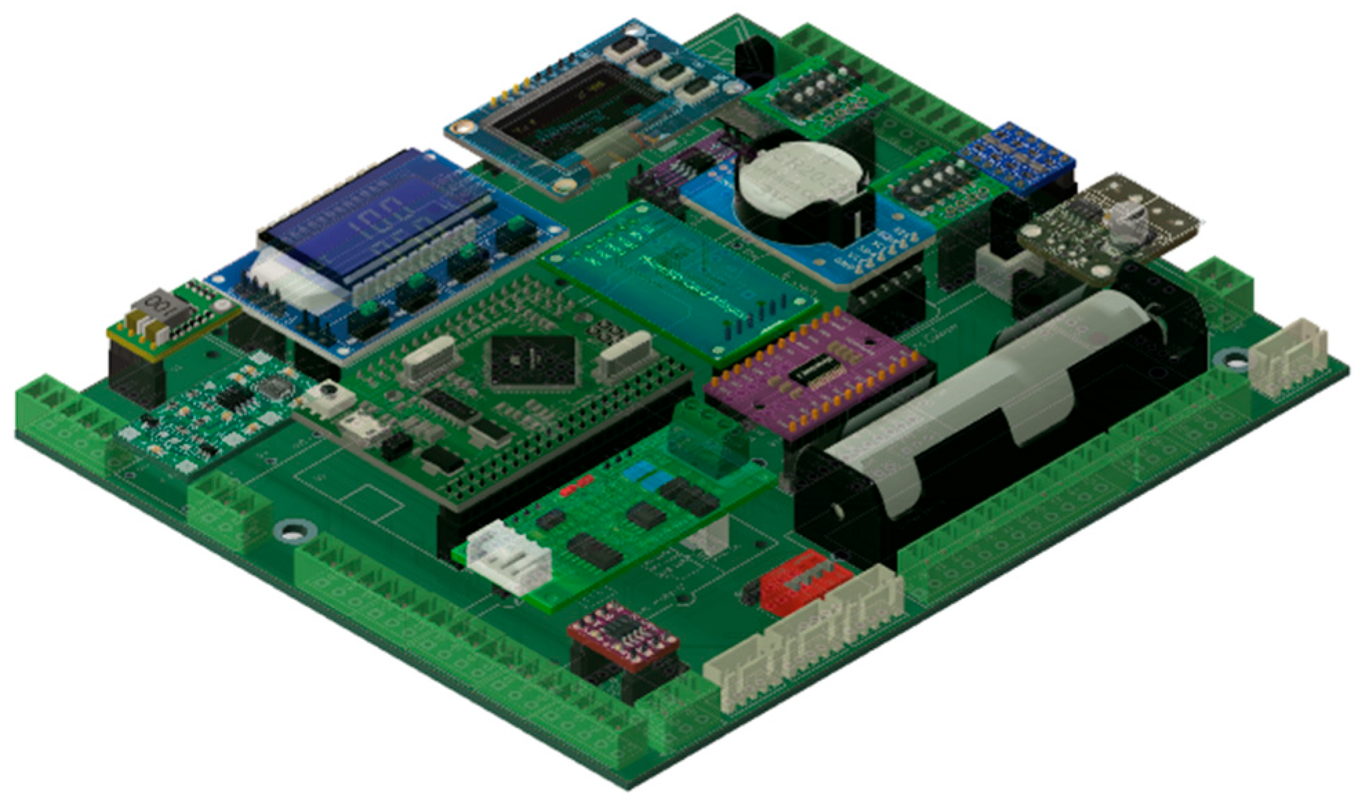
Figure 4.
Example of the exploded mounting schemes.
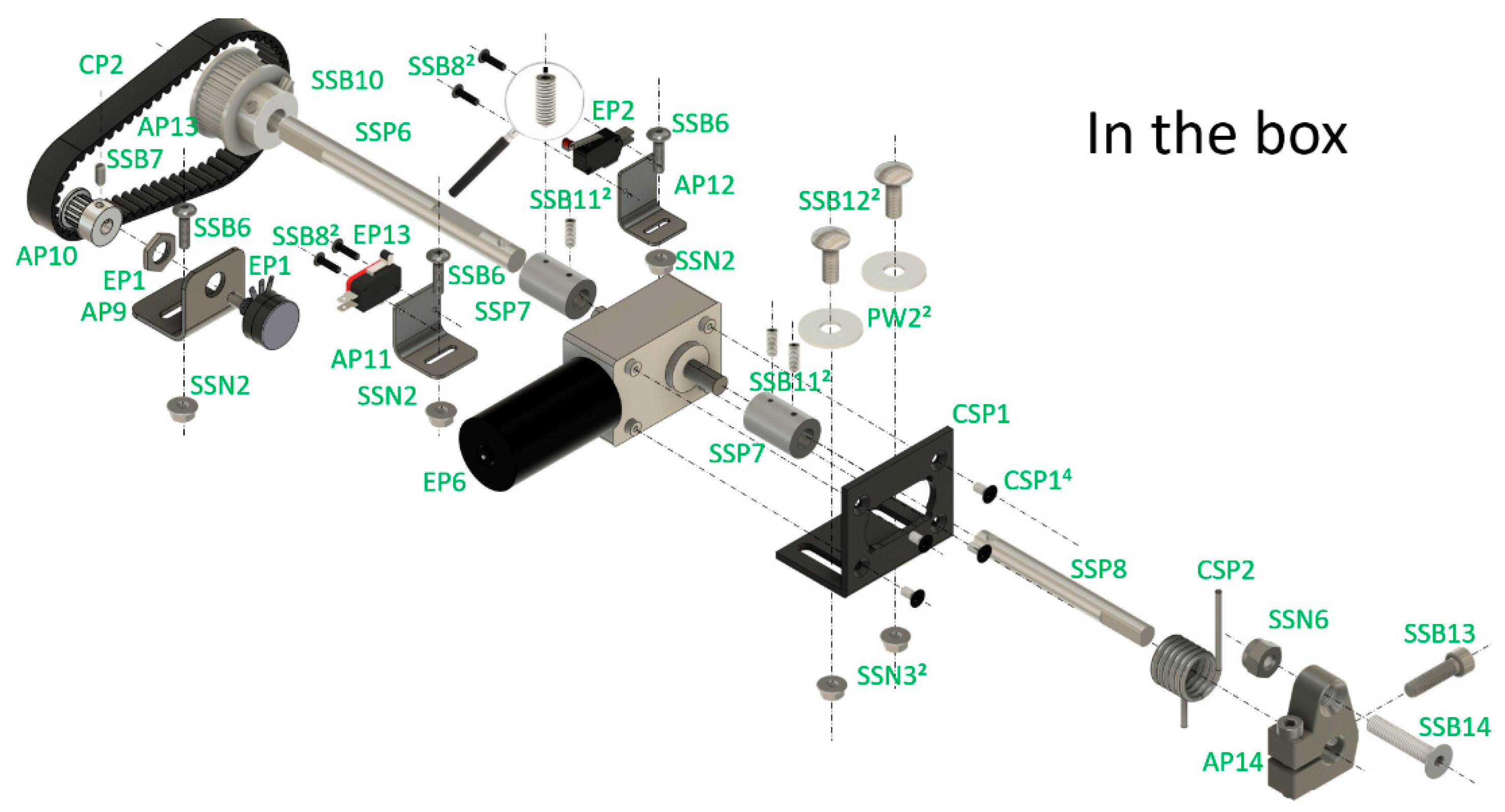
Figure 5.
“Serial” configuration of the chambers with a unique air analyzer, a pneumatic multiplexer, and an external data logger, with data and power lines. Only one chamber can close at a time.
Figure 5.
“Serial” configuration of the chambers with a unique air analyzer, a pneumatic multiplexer, and an external data logger, with data and power lines. Only one chamber can close at a time.
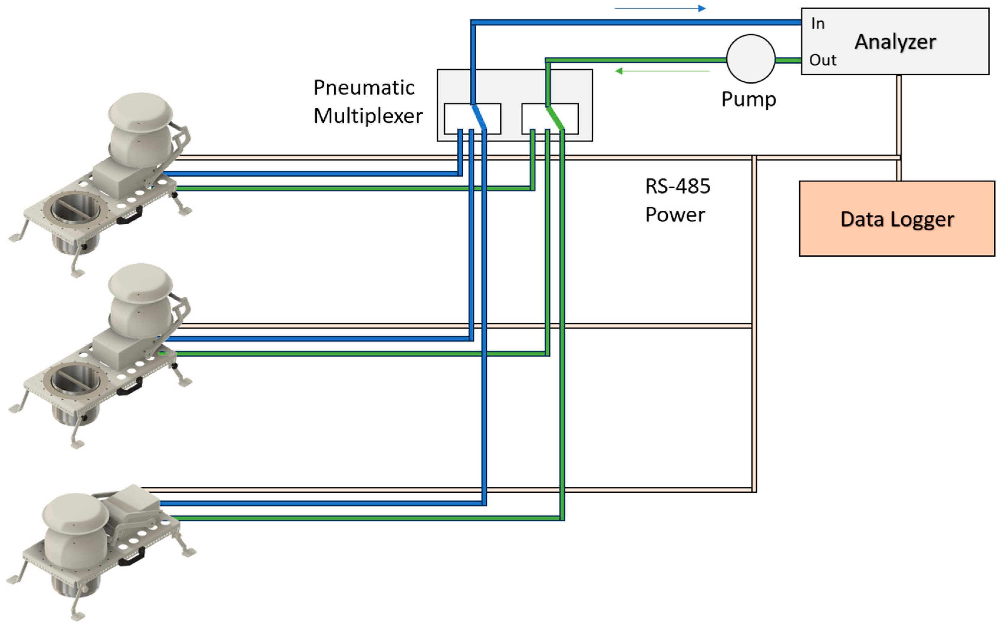
Figure 6.
“Autonomous” configuration of the chambers, (a) with embedded sensors and an optional external datalogger, featuring a data and power line. (b) All chambers are totally autonomous without data or power lines. In both cases, all chambers can close and measure simultaneously.
Figure 6.
“Autonomous” configuration of the chambers, (a) with embedded sensors and an optional external datalogger, featuring a data and power line. (b) All chambers are totally autonomous without data or power lines. In both cases, all chambers can close and measure simultaneously.
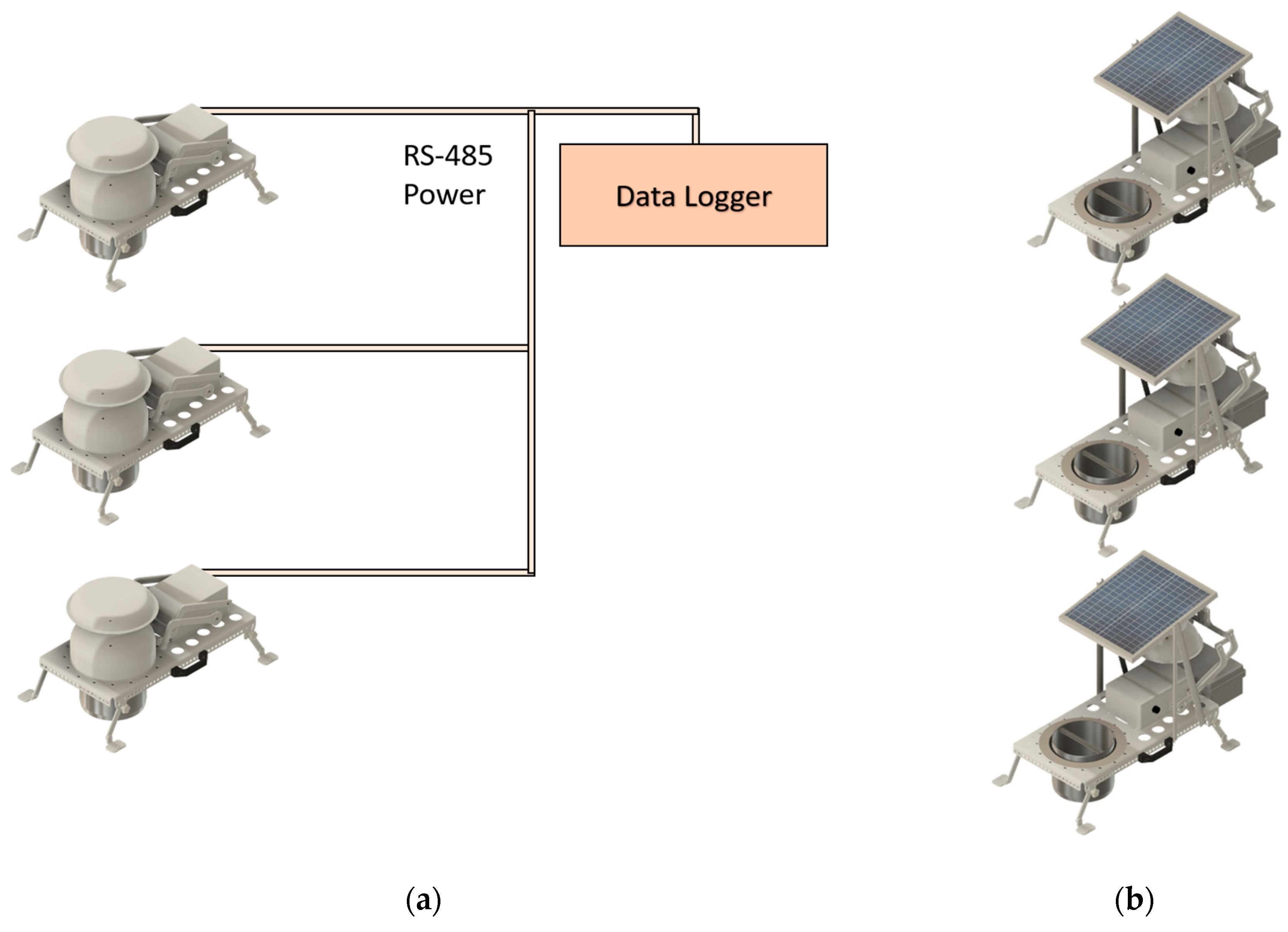
Figure 7.
Chambers with anti-pinch grids.
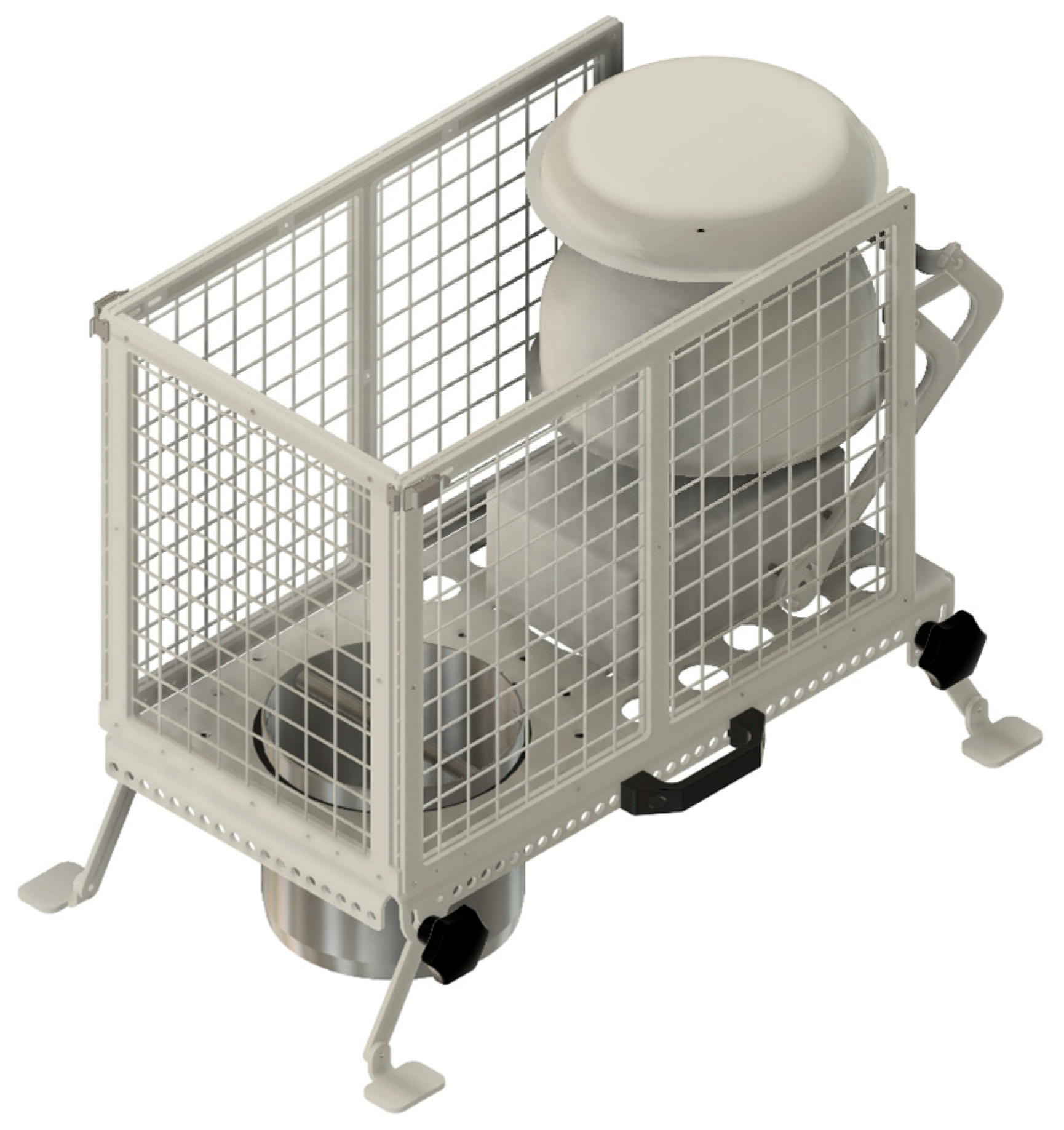
Figure 8.
Floating chambers with a transparent cloche and collar, solar panel, PAR sensor, and battery.
Figure 8.
Floating chambers with a transparent cloche and collar, solar panel, PAR sensor, and battery.
Disclaimer/Publisher’s Note: The statements, opinions and data contained in all publications are solely those of the individual author(s) and contributor(s) and not of MDPI and/or the editor(s). MDPI and/or the editor(s) disclaim responsibility for any injury to people or property resulting from any ideas, methods, instructions or products referred to in the content. |
© 2026 by the authors. Licensee MDPI, Basel, Switzerland. This article is an open access article distributed under the terms and conditions of the Creative Commons Attribution (CC BY) license (http://creativecommons.org/licenses/by/4.0/).
Copyright: This open access article is published under a Creative Commons CC BY 4.0 license, which permit the free download, distribution, and reuse, provided that the author and preprint are cited in any reuse.


