Submitted:
15 January 2026
Posted:
15 January 2026
You are already at the latest version
Abstract
High-level roof borehole is one of the core technologies for gas control in high-gas mines in China. However, in soft and fragmented rock strata, the influence of mining-induced stress disturbance often causes compression-torsion deformation, borehole wall collapse, or dislocation when the borehole passes through the coal-rock interface due to lithological differences. This results in blockage of the gas flow channel or even borehole failure. Existing borehole protection technologies generally suffer from issues such as heavy screen pipes, low construction efficiency, and difficulty in large-scale application. To address these problems, this study, based on the engineering background of Xin’an Coal Mine, developed a stainless-steel socket-type screen pipe with an “upper large, lower small” structure by systematically analyzing the necessity of borehole protection and the stress characteristics of protective pipes. A stepwise insertion method driven by the drill rig’s jacking system was adopted to achieve full-length borehole protection in soft rock strata. Meanwhile, the YZT-Ⅱ rock formation borehole detector was used to analyze borehole wall stability, and a comparative experiment between protected and unprotected boreholes was carried out at the 14230 working face of Xin’an Coal Mine. The results indicate that the rock formation detector identified the coal-rock interface as the high-incidence zone of borehole collapse, whereas the novel protective screen pipe effectively maintained borehole wall integrity in this zone. The gas drainage concentration of protected boreholes remained stable above 80%, with a pure extraction flow rate of ≥0.2 m3/min, and the total extracted gas volume was 8–10 times higher than that of unprotected boreholes (with extraction concentrations of 30%–45% and pure flow rates of 0.03–0.06 m3/min). Furthermore, based on a fluid-solid coupling model and field data, the optimal spacing between high-level roof boreholes under these geological conditions was determined to be 3.0–3.5 m, with an optimal number of three boreholes. The proposed novel screen pipe and corresponding construction technology effectively solve the problems of borehole collapse and blockage in high-level roof boreholes within soft and fragmented rock strata, significantly improving gas drainage efficiency and borehole utilization. This provides reliable technical support for gas control in mines with similar geological conditions and demonstrates broad application potential.
Keywords:
high-level roof borehole
; protective screen pipe
; coal-rock interface
; directional drilling
; borehole wall
1. Introduction
In high-gas mines, the presence of abundant gas disrupts the equilibrium state of adsorption in fractured coal seams, releasing large quantities of gas into the mining space of the working face. The vortex effect in the upper corner often hinders adequate gas migration, leading to excessive gas accumulation in that region [1,2,3]. To mitigate this issue, common practices include drilling boreholes into the fracture zone above the coal seam roof using conventional or directional rigs, installing pipes at the rear of the goaf to intercept gas migration from the old goaf to the working face, or inserting extraction pipes into the upper corner for gas drainage. During mining, disturbance and damage cause a large amount of adsorbed gas to transform into free gas, which accumulates in the fracture zone of the roof due to buoyancy effects. This accumulation poses the greatest risk for gas management at the working face [4,5,6,7]. Therefore, gas drainage from the roof fracture zone is one of the most effective methods for controlling gas at the working face [8,9]. In conventional roof gas drainage, boreholes are drilled through the coal seam roadway into the roof above the coal seam. However, collapse frequently occurs at the coal-rock interface, and boreholes drilled through rock strata are often blocked or damaged by shearing during overburden movement, resulting in premature borehole failure.
To address borehole collapse, Klishin et al. [10] developed 73 mm high-toughness, high-strength drill rods to solve issues such as thread sticking, bending, and breakage encountered during the construction of large-diameter high-level roof boreholes, meeting the technical requirements of long directional drilling. Lu [11], Li [12], and others developed countermeasures for borehole collapse in fragile roof strata at Guqiao Coal Mine by adopting measures such as grouting reinforcement, enlarging the borehole diameter in fragile sections, and increasing the drilling inclination angle. These methods effectively prevented borehole collapse. To further reduce collapse risks, Duan et al. [13] analyzed the shortcomings of existing rotary and sliding directional drilling technologies for high-level boreholes and proposed a newly developed composite directional and large-diameter reaming technology. They introduced an integrated control and composite reaming technique and provided a technical outlook for complete-screening protection in high-level roof boreholes. Nian [14] proposed replacing the drill rig’s clamping device and rotary chuck to mitigate collapse problems, employing a clamping–pushing method to insert 108 mm rigid screen pipes throughout the borehole. However, the method required 4–6 workers to align and tighten the heavy pipes on both sides while ensuring no looseness, resulting in low construction efficiency and difficult large-scale application. Although roof borehole screen insertion technologies have been applied in some mines, the issues of heavy screen pipes, low efficiency, and poor scalability remain unresolved.
To overcome these limitations, this study proposes a novel large-diameter directional roof borehole protection device capable of efficiently inserting protective screen pipes while maintaining high-efficiency gas extraction during face retreat. This technology saves both manpower and time, maximizes borehole utilization and extraction efficiency, and can be widely applied in coal mines requiring high-level roof boreholes.
2. Construction and Stress Analysis of High-Level Roof Boreholes in Soft and Fragmented Coal Seams
2.1. Construction Process
High-level roof boreholes are one of the primary methods for gas control in high-gas or outburst-prone longwall faces [15,16,17]. The main construction process involves establishing a drilling site within the return airway of the working face or in an adjacent parallel roadway after the working face is formed. Boreholes are then drilled toward the roof area above the retreating working face [18,19,20]. During mining, as the working face retreats, the overlying strata above the coal seam are affected by gravitational and mining-induced stresses, forming fracture zones of varying development. Directional long boreholes are distributed within the rock strata located at a certain distance above the coal seam roof [21]. The boreholes are initiated from the coal roadway and drilled upward at an inclination angle of 1°–3°. Drilling continues slowly until the borehole enters a specific rock layer within the fracture zone. After reaching this level, drilling proceeds horizontally along the advancing direction of the working face. The total length of each borehole is generally 400–500 m, with a horizontal section length of 300–400 m. This configuration ensures safe advancement of the working face within the corresponding horizontal range. Effective gas drainage from these boreholes prevents gas accumulated in fractured coal or surrounding rocks after mining from migrating into the mining space and gathering in the upper corner, thus ensuring that gas concentration in the upper corner remains below the regulatory limit.
High-level directional roof drilling is performed at a certain height above the coal seam roof. During the drilling or retreating process, compression–torsion deformation or uneven stress at the coal-rock interface may cause borehole wall displacement or misalignment [22]. Local rock blocks within the roof may detach, leading to borehole blockage. Installing protective screen pipes inside the directional roof boreholes effectively resolves such issues, preventing total borehole failure and low-efficiency drainage. The comparison between open-hole drilling and protected borehole drilling using screen pipes is shown in Figure 1(a).
Directional drilling construction primarily utilizes the ZDY-12000LD directional drilling rig, a Φ73 mm + Φ96 mm/Φ153 mm composite guiding bit, and matching screw drilling tools. The “one-time drilling and three-stage reaming” process is adopted. The main borehole is drilled using a Φ73 mm screw motor combined with a Φ98 mm bit. The first reaming uses a Φ89 mm reaming rod with a Φ133 mm bit, the second reaming uses a Φ89 mm reaming rod with a Φ165 mm bit, and the third reaming uses a Φ89 mm reaming rod with a Φ203 mm bit. To ensure the borehole reaches the designed target stratum, a while-drilling measurement system is employed to track and correct the borehole trajectory in real time. The borehole trajectory obtained after directional measurement and construction is illustrated in Figure 1(b).
2.2. Necessity of Borehole Protection in Directional Drilling within Soft and Fragmented Rock Strata
It is well known that geological conditions are one of the main intrinsic cause of instability and failure of gas drainage boreholes. In soft coal seams, geological structures destroy the original fracture network of the coal, weakening the coal body. As a result, borehole walls deform, reducing the effective cross-sectional area for gas migration. In severe cases, the borehole may collapse completely, obstructing gas flow channels [23]. To quantitatively analyze the influence of the coal-rock mass on borehole wall stability, mechanical parameter tests were conducted on coal samples from the No. 21 coal seam of Xin’an Mine. The stress–strain curve of the coal-rock mass under uniaxial compression is shown in Figure 2.
As shown in the curve, the coal-rock mass undergoes a pore compaction stage from point 0 to point A, during which internal pores are compressed. From point A onward, the material enters the linear elastic deformation stage, reaching its elastic limit at point B. Beyond the elastic limit, when the strain exceeds approximately 0.6, new microcracks begin to form, marking the plastic deformation stage. Between points B and C, crack propagation within the coal-rock mass occurs slowly and steadily. From point C onward, as stress increases beyond 0.95 of the peak value, plastic failure propagates rapidly, and strain increases significantly. When the peak stress is reached at point D, the material reaches its ultimate strength, and failure occurs. Therefore, when boreholes pass through coal-rock interfaces or geological structural zones, the uneven stress distribution on the borehole wall can easily cause local cracking or displacement. The resulting chain reaction may induce systematic collapse within the entire borehole volume. Hence, incorporating protective support of adequate strength to stabilize the borehole wall is essential for maintaining borehole integrity and ensuring effective gas drainage.
2.3. Stress Analysis of Borehole Protection in Directional Drilling within Soft and Fragmented Rock Strata
The modified Mohr–Coulomb strength criterion with the Fenner formula is used as the ultimate equilibrium condition. Based on this condition, the plastic zone radius and the elasto-plastic stress solution of the coal-rock mass are calculated. A micro-element at any point around the cross-section of a directional long borehole is selected as the analysis object to evaluate the borehole stress state under the soft, low-permeability coal-rock conditions of Xin’an Mine [24,25]. The stress diagrams of the micro-element for borehole protection are shown in Figure 3(a) and 3(b). Assuming that the micro-element has a thickness of dr, a width of rdθ, and is located at a distance r from the borehole center, the stress equilibrium equation, deformation equation, and constitutive relation can be established.
Within the current model range, the gravitational effect on the coal-rock mass is negligible compared with the in-situ stress. Therefore, by projecting onto the r-axis, the stress equilibrium equation among various stresses can be expressed as follows:
where r is the radius of the micro-element (m), θ is the polar coordinate angle (rad), is the radial stress in the plastic zone (MPa), and is the tangential stress in the plastic zone (MPa).
During borehole collapse, the strength of the protective screen pipe resists the pressure caused by collapse, reducing borehole deformation. Assuming that the outer diameter of the screen pipe is equal to the borehole diameter and that the outer wall of the pipe fits closely against the borehole wall, the pipe is subjected to both the overlying coal mass pressure and the internal gas or water pressure. Therefore, the installation of a protective screen pipe in a borehole can be considered as a micro-tunnel support problem. The screen pipe acts as the load-bearing structure. It is subjected to an external uniform pressure Pa and an internal uniform pressure Pb. The pipe thickness is d, the outer radius is b, and the inner radius is a. Based on the principle of axisymmetry, the stress and micro-deformation of the screen pipe can be expressed as:
where ,. The micro-deformation is: . Here, A and C are fitting constants, r is the radius, u is the displacement, and are the radial and tangential stresses on the pipe, and are the corresponding radial and tangential strains, E is the elastic modulus, and ν is the Poisson’s ratio.
By substituting r=b, and r=a,, we obtain ,. Hence, the coefficients are: , . By substituting these coefficients into the stress equilibrium and micro-deformation equations of the pipe, we obtain: , . According to the relationship between stress and strain, replacing E with and v with yields:
The maximum support stress and micro-deformation occur at the inner and outer boundaries of the protective pipe, corresponding to r = b. Thus: ,,. At the inner side of the pipe (r = a): ,,. For the outer side (r = b): ,The main purpose of inserting a protective screen pipe into soft coal seams is to prevent borehole collapse and to maintain a gas flow channel within the coal seam. Assuming that the internal pressure of the protective pipe is 0 MPa (Pa = 0), the stress state of the protective pipe can be expressed as:
After the gas drainage screen pipe is inserted into the borehole, it is subjected to multiple forces including its self-weight, the pulling and pushing forces, and the frictional forces between the pipe and the borehole wall. Therefore, analyzing the stress state of the screen pipe within the borehole is crucial for selecting a suitable protective screen pipe. In practical operations, the designed length of pre-drainage gas boreholes usually exceeds 100 m. Due to geological factors in soft coal seams, the borehole trajectory often deviates from its designed path during drilling, and bending is common after completion. When inserting the screen pipe into the borehole, it is mainly subjected to its self-weight (W), the contact forces (N1, N2, N3) between the pipe and the borehole wall, and the pulling or pushing forces (T1, T2) applied during insertion or when encountering resistance. During repeated pushing and pulling, frictional forces (μN1, μW + μN2, μN3) act on the pipe. Under these combined forces, the screen pipe experiences compression, torsion, and tensile deformation within the borehole.
After borehole completion, to enhance borehole stability in soft coal seams, a protective screen pipe is installed and connected to the gas drainage network. During gas extraction, due to low borehole stability and mining-induced disturbances, collapse may occur, which imposes compressive forces on the screen pipe. The degree of compression depends on the severity of the collapse. Here, W represents the self-weight of the screen pipe, N1 is the contact force between the pipe and the borehole, and N2 is the pressure from collapsed coal particles on the pipe. The stress condition of the screen pipe during borehole collapse is shown in Figure 3(b). From the analysis of the forces acting on the screen pipe inside the borehole, it is evident that during insertion and collapse, the protective screen pipe primarily experiences axial tension, torsional deformation, and radial compression failure. Installing a standard protective pipe within gas drainage boreholes in soft coal seams can effectively enhance borehole stability, as the pipe strength can withstand a certain degree of collapse pressure, ensuring a gas flow channel even during partial borehole failure.
3. Directional High-Level Borehole Protection Technology
3.1. Composition of the Protective Screen Pipe
Directional high-level boreholes are drilled upward from the coal seam into the overlying rock strata. Stress concentration and displacement misalignment are likely to occur at the coal-rock interface, where boreholes passing through this region are easily damaged or broken due to rock block cutting or torsional deformation. The installation of a protective screen pipe inside the borehole can effectively preserve the integrity of the gas flow channel throughout the borehole. The protective screen pipe serves as a borehole protection device for high-level roof boreholes. It is composed of multiple short screen sections with filter holes. After borehole drilling is completed, these short sections are connected sequentially and inserted into the borehole to achieve full-length protection. The short sections are designed with a socket-type connection, where the upper end has a larger diameter than the lower end. This design offers several advantages: (1) It enables efficient and convenient insertion of the protective screen pipe into the borehole. (2) It ensures effective interconnection of the protective pipes while allowing them to naturally detach under gravity when the fractured rock strata beneath collapse. This not only reduces extraction resistance but also maintains the protective function of the screen pipe in the effective section of the borehole. A schematic diagram of the protective screen pipe is shown in Figure 4.
3.2. Development and Installation of the Protective Screen Pipe
Two types of protective screen pipes with different materials and structures were developed. The first type is a solid polyethylene (PE) pipe, and the second type is a stainless-steel pipe. The first type, a PE pipe with a diameter of 50 mm, is mainly used for the section from the borehole collar to about 10 m inside the coal-rock interface in upward-crossing boreholes. Its function is to prevent borehole collapse at the coal-rock interface. The second type, a stainless-steel protective screen pipe, has 8–10 mm diameter filter holes on its wall and an overall diameter of approximately 100 mm. It features different diameters at the upper and lower ends. This pipe is mainly used for the section from 10 m inside the coal-rock interface to the end of the borehole, providing protection against shear dislocation or blockage by rock particles in the horizontal section within the rock strata. The upper end of the stainless-steel pipe, which faces the goaf, has a diameter of 40 mm, while the lower end, facing the borehole collar, has a diameter of 36 mm. Each section of the stainless-steel pipe is 0.5 m in length, and the sections are connected by inserting the upper end of one section into the lower end of the next. The pipes are then successively connected and inserted into the borehole.
The diameter of the protective screen pipe is determined based on the final borehole diameter achieved by the directional drilling equipment used in the mine. The diameter of the protective screen pipe must always be smaller than that of the borehole to ensure smooth insertion. The pipe is made of high-strength stainless steel, and the fabrication parameters of the protective screen pipe are shown in Table 1. The socket-type joint with an “upper large, lower small” design is adopted mainly because the pipes are inserted into the borehole section by section using the jacking mechanism of the drilling rig. This design ensures both reliable interconnection and smooth detachment of the front-end pipes when they enter deep fracture zones within the goaf, preventing excessive joint resistance that would otherwise hinder detachment.
The installation process of the protective screen pipe is as follows: (1) Sequentially connect the stainless-steel pipes and PE pipes according to their upper and lower ends; (2) Manually insert the pipes into the borehole during the connection process; (3) When the insertion depth exceeds the manual operation range, use the drill rig’s jacking system to push the pipe along the borehole trajectory until it reaches the designated position. The lower end of the stainless-steel protective pipe adopts a threaded connection. When large fractures form in the mining-affected zone, the distal sections of the stainless-steel pipes will gradually detach and fall under gravity. Consequently, the effective extraction length of the borehole shortens progressively as the working face advances. This design ensures that the borehole remains protected within its effective length while simultaneously reducing the extraction resistance.
3.3. Pipe Analysis of Technological Advantages
The application of the protective screen pipe represents a new process introduced on the basis of conventional gas drainage through sealed high-level roof boreholes after open-hole drilling. This technique modifies the traditional construction procedure of high-level roof boreholes. Specifically, after the second reaming and before borehole sealing, the protective screen pipe is manually inserted into the borehole to achieve full-length protection throughout the high-level borehole. This process effectively addresses several difficulties encountered during gas extraction.
(1) The coal-rock interface is the weakest zone of the borehole wall due to uneven stress distribution and abrupt stress changes. Klishin et al. [26] conducted experimental and numerical analyses of the stress and failure characteristics at the coal-rock interface. Their findings indicate that differences in lithology result in various stress conditions and obstructed fracture propagation at the interface, which collectively lead to diverse failure modes, making this region highly prone to borehole collapse. To address this issue, tempered stainless-steel screen pipes are used to reinforce the coal-rock interface area, ensuring an unobstructed gas flow channel throughout the entire extraction period.
(2) Because directional long boreholes are drilled horizontally above the mined coal seam and are usually inclined upward at a small angle at the borehole end to facilitate slag discharge, the development of fractures in the caving and fracture zones of the goaf causes rocks of various particle sizes to fall and potentially damage or block the borehole channel. The use of full-length screen pipe protection, featuring a socket-type “large upper end and small lower end” structure, effectively addresses this problem. The design allows the protective pipe to maintain protection under dynamic roof conditions while ensuring that the pipe can naturally detach upon impact from falling rocks, thus ensuring timely and reliable protection of the borehole in response to roof deformation.
4. Determination of Key Parameters for Directional High-Level Roof Boreholes
4.1. Fluid-Solid Coupling Model of Coal-rock Media under Pressure-Relief Conditions
During coal seam extraction, displacement and stress variation in the overlying strata of the goaf generate extensive plastic zones, which are mainly distributed in front of the working face, within the fracture zone of the goaf, and around gas drainage boreholes. Therefore, when studying gas migration behavior, the influence of plastic deformation on gas transport cannot be neglected. Previous studies have typically established gas-solid coupling models based on elastic deformation, ignoring the existence of plastic zones. Hence, when establishing a mathematical model, the effect of plastic failure should be fully considered.
To facilitate numerical simulation of the mathematical model, the following assumptions are made for boundary conditions: ① The coal-rock mass is a dual-porosity medium containing both pores and fractures. Gas in the fracture medium obeys Darcy’s law, while gas in the pore medium follows Fick’s diffusion law. ② The coal-rock mass is considered a homogeneous, isotropic, linear elastic body. ③ The effects of temperature and external environmental changes are neglected, and deformation is assumed to occur under isothermal conditions.
(1) Failure Criterion of the Coal-Rock Mass
According to the Drucker-Prager failure criterion, which is consistent with the Mohr–Coulomb theory, the plastic failure of coal can be expressed as:
where I_1 is the first invariant of the stress tensor, C is the cohesion (MPa), and φ is the internal friction angle (°). I_1 can be expressed as:
J2 is the second invariant of the deviatoric stress, and I_2is the second invariant of the stress tensor, defined as:
During plastic deformation, the cohesion of the coal body gradually decreases, leading to reduced strength. Under continued stress, the coal-rock mass experiences fracturing, resulting in a rapid increase in permeability.
(2) Permeability Equation
For computational convenience, the equivalent plastic strain and the initial equivalent plastic strain in the residual stress stage are introduced. The plastic strains , , and correspond to the X, Y, and Z directions, respectively.
Accordingly, the permeability can be expressed as:
Since the primary control parameters for plastic failure include cohesion and the internal friction angle, and the latter can be neglected according to previous studies, an elastoplastic model governed primarily by cohesion can be expressed as:
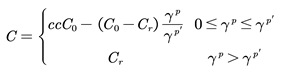 where is the initial cohesion before the peak stress, and is the residual cohesion in the post-peak stage.
4.2. Influence Radius of Gas Drainage by High-Level Roof Boreholes in the Fracture Zone
To investigate the gas drainage behavior of high-level roof boreholes, a geometric model with dimensions of 10 m × 10 m was established. The drainage borehole was located at the center of the model, with a diameter of 150 mm, and was arranged within the rock strata. The lower boundary of the model was set as a fixed boundary, the upper boundary as a pressure boundary, and both lateral boundaries were set as roller supports. Based on the mechanical parameters of coal and rock obtained from field measurements in the No. 21 coal seam of Xin’an Coal Mine, the numerical model parameters used in this study are listed in Table 2.
By applying the established fluid-solid coupling model of the coal-rock medium under pressure-relief conditions, and substituting the relevant parameters of the high-level borehole in the fracture zone and the coal-rock medium, the pressure-relief ranges under different extraction durations were obtained. Taking Borehole No. 2 as an example, the variation of the coal-rock mass in the pressure-relief zone at different drainage times is shown in Figure 5.
As shown in Figure 5, the influence range of the high-level roof borehole on the gas pressure in the fracture zone gradually expands with the increase in drainage time. After 50 days of gas extraction, the affected zone, characterized by reduced gas pressure, extends to approximately 5 m. As extraction continues, this influence range expands significantly. After 150 days, the gas pressure reduction zone within the fracture zone extends to about 7 m, within which the gas pressure has nearly dropped to zero. To further compare the trend of gas pressure reduction in the fracture zone under different extraction durations, the simulation data were exported and fitted for analysis. The resulting dynamic variation curves of gas pressure over time are shown in Figure 6.
As illustrated in the figure, the gas pressure near the borehole exhibits a distinct stepwise mutation pattern. This phenomenon is attributed to the existence of a plastic failure zone around the borehole, where pressure relief leads to a reduction in the gas pressure gradient. Based on the analysis of the simulation cloud map and the variation of the pressure–time curve, it can be concluded that when the borehole diameter is 150 mm, a spacing of 3.0–3.5 m between high-level boreholes is optimal. This spacing maximizes the gas drainage efficiency during the extraction period while effectively avoiding mutual interference between adjacent boreholes.
4.3. Determination of the Optimal Number of Boreholes
The required number of boreholes can be determined using the following equation:
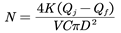 where is the absolute gas emission rate of the working face (m3/min), is the absolute gas volume discharged through ventilation (m3/min), K is the unevenness coefficient (ranging from 1.2 to 1.7), V represents the gas velocity inside the borehole sealing pipe (generally 5 m/s), and C denotes the gas concentration in the extraction pipeline (%), typically 50%.
Based on field measurements, the absolute gas emission rate of the retreating working face in Xin’an Coal Mine ranges between 10 and 20 m3/min. Substituting these parameters into Equation (12) yields N=5.2. To maximize the gas extraction efficiency and ensure the safe production of the working face, it is considered reasonable to arrange approximately 5 to 6 boreholes.
5. Engineering Application
5.1. Borehole Formation Conditions
To effectively evaluate the gas extraction performance of high-level roof boreholes with and without protective screen pipes, and to account for possible drilling distance deviations, six boreholes were designed and constructed based on the drilling parameters determined in Section 3.4. A safety coefficient of 1.5 was considered to ensure extraction reliability. Among these, Boreholes No. 1, 3, and 5 were equipped with full-length protective screen pipes consisting of multiple short sections, while Boreholes No. 2, 4, and 6 remained as unprotected (open) boreholes. The actual borehole trajectories are shown in Figure 7(A).
To verify whether borehole collapse occurred after construction, a rock formation borehole detector was used to examine the internal morphology of each borehole after drilling but before the insertion of screen pipes. The rock formation borehole detector comprises a CCD micro-probe, image converter, light source, amplifier, signal converter, stabilized power supply, and digital video recorder. It is used to detect, measure, and record cracks and fissures, and to capture visual images stored on videotape. The configuration of the rock formation borehole detector is shown in Figure 7(B-C).
A borehole with a diameter of 75 mm was drilled into the rock formation, and the rock fragments inside the hole were flushed out with water. The CCD probe, power source, and digital video recorder were connected through a cable, and the CCD probe was fixed onto a supporting tube. After positioning the CCD probe at the borehole entrance, the system power was switched on, and the video recorder was activated. The probe was then inserted into the borehole using a metal rod until it reached the bottom. The connectors were plugged in, the power was turned on, and the recording button was activated to start image collection. During the recording process, both the starting time and the distance from the borehole entrance were noted. The camera was then slowly withdrawn outward, and images were recorded at regular distance intervals until it reached the borehole opening. The borehole wall conditions at different positions inside the borehole captured by the detector are shown in Figure 8.
As shown by the borehole wall images in Figure 8, Figure 8(A) and 8(B) represent the rock strata segment at the front of the coal-rock interface. It can be observed that the borehole wall remained relatively intact, and the influence of surrounding rock properties and drilling disturbance was minimal. Figure 8(C) illustrates the internal morphology of the borehole at the coal-rock interface, while Figure 8(D) shows the wall of the coal seam segment behind the interface. These images indicate that borehole collapse and blockage were highly likely to occur near the coal-rock interface, primarily due to the significant mechanical property differences between the coal seam and the overlying rock strata.
5.2. Gas Extraction Performance
To further investigate the differences in gas extraction performance, continuous monitoring of the high-level roof boreholes was conducted. For measurement convenience, three unprotected boreholes and three screen-protected boreholes were each connected to a manifold pipe for gas collection. The key extraction parameters, including gas concentration and pure gas flow rate, were recorded. The variation in gas extraction parameters is shown in Figure 9.


As indicated by the trend in Figure 9, there was a significant difference in gas extraction performance between the unprotected and protected boreholes. The extraction concentration of unprotected boreholes remained within the range of approximately 30%–45%, with pure gas flow rates generally between 0.1 and 0.2 m3/min, and an average single-borehole flow rate of 0.03–0.06 m3/min. In contrast, the extraction concentration of protected boreholes consistently exceeded 80%, with a single-borehole pure gas flow rate maintained above 0.2 m3/min.
During the first 30 days of mining at the 14230 working face, the face advancement rate was relatively slow, resulting in higher gas concentrations in the upper corner (approximately 0.6%–0.8%). During the subsequent 30–60 days, as the advancement rate increased significantly, the upper corner gas concentration decreased accordingly. The main reason for this difference is that the unprotected boreholes, with their distal ends located within the roof fracture zone, were easily blocked by fragmented rock debris accumulated under the action of swelling and caving, which obstructed gas flow and reduced extraction efficiency. In contrast, the protected boreholes avoided such issues, maintaining unobstructed gas flow channels along the entire borehole length.
Furthermore, based on the extraction performance and face advancement data, it was found that during the initial 15 days when the high-level roof boreholes entered the goaf fracture zone, the borehole walls were more susceptible to damage from surrounding rock stress. This was particularly evident because the horizontal section length of the high-level roof boreholes exceeded 300 m, and the overlying rock stress distribution above the open-off cut was highly uneven. Such uneven stress often led to borehole wall blockage or torsional deformation, narrowing the gas flow channel or even causing borehole failure. These observations highlight the significant advantages of using stainless-steel protective screen pipes in maintaining borehole stability and ensuring long-term gas drainage performance.
6. Discussion
6.1. Stability of the Coal-Rock Interface and Borehole Visualization Results
To identify the critical instability zones of high-level roof boreholes in soft and fragmented rock strata, a YZT-Ⅱ rock formation borehole detector was employed to visually observe the borehole wall morphology of both unprotected and protected boreholes at the 14230 working face of Xin’an Coal Mine. The observation covered the entire borehole length, focusing particularly on the coal-rock interface and the 10 m zones above and below it. The detection results showed that the collapse rate of unprotected boreholes at the coal-rock interface reached 100%, characterized by wall collapse and rock block accumulation. Although the wall integrity in the rock section ahead of the interface and in the coal section behind it was relatively better, local fractures were still present. In contrast, boreholes protected with the newly developed screen pipe maintained 100% wall integrity across the entire borehole, with no evident deformation or compression damage observed in the screen pipe.
The high collapse rate at the coal-rock interface is essentially attributed to stress concentration caused by lithological differences. As analyzed in Section 2.3, the mechanical properties of coal and roof sandstone differ significantly, resulting in compressive–torsional deformation and shear misalignment at the interface under mining-induced stress disturbance. In unprotected boreholes lacking structural support, such deformation rapidly leads to wall collapse. However, the new stainless-steel protective screen pipe can transmit radial stress to counteract confining rock pressure, effectively inhibiting crack propagation. Furthermore, the PE protective pipe installed at the borehole collar provides secondary protection for the coal section within 10 m inside the coal-rock interface, preventing localized collapse in the weak coal zone.
The visualization results obtained from the YZT-Ⅱ detector not only validate the scientific understanding that the coal-rock interface is a “high-incidence zone of borehole collapse” but also provide direct empirical evidence supporting the design range of the protective screen pipe . This approach compensates for the limitation of conventional mechanical analyses, in which the borehole wall morphology cannot be directly observed.
6.2. Comparative Analysis of Gas Extraction Performance of the Novel Protective Screen Pipe
At the 14230 working face, three groups of protected boreholes and three groups of unprotected boreholes were used for a 60-day parallel extraction experiment. The key parameters are listed in Table 3.
The gas extraction concentration of the protected boreholes was significantly higher than that of the unprotected ones, and no “sudden concentration drop” phenomenon was observed in the protected boreholes. In terms of flow rate, the average pure gas flow of each protected borehole was 3.3–6.7 times greater than that of the unprotected boreholes. Over 60 days, the total extracted gas volume of the protected boreholes was 8–10 times higher than that of the unprotected ones, consistent with the fluid-solid coupling model prediction that “the gas flow resistance decreases by 70% after borehole protection.” The enhanced extraction efficiency of the protected boreholes results from the combined effects of “flow channel stability” and “flow resistance optimization.” On the one hand, the socket-type structure of the stainless-steel screen pipe allows each section to naturally detach under gravity when the overlying strata collapse, preventing total blockage caused by the locking or jamming of the entire pipe assembly. This design effectively resolves the problem of “traditional rigid screen pipes being heavy and prone to jamming.” In addition, only two operators, assisted by the drill rig jacking mechanism, are required for installation, resulting in a threefold improvement in construction efficiency compared with traditional methods. On the other hand, the 8-10 mm screen holes on the pipe wall ensure adequate gas permeability while blocking rock fragments from entering the flow channel, thereby preventing the “rock accumulation-flow blockage” cycle commonly observed in unprotected boreholes.
Compared with previous studies, the protective screen pipe developed in this research does not require additional grouting materials or extended construction time, thereby reducing costs by approximately 40%. Moreover, it avoids secondary blockage problems associated with grout shrinkage. Focusing on post-drilling protection, this technique directly addresses the long-term gas drainage requirements of soft and fragmented strata and demonstrates broader applicability.
6.3. Validation of the Fluid-Solid Coupling Model and Optimization of Borehole Parameters
Based on the modified Drucker-Prager criterion and the dual-porosity seepage theory, a fluid-solid coupling model for high-level roof boreholes in soft and fragmented rock strata was established. Using the mechanical parameters of the No. 21 coal seam in Xin’an Coal Mine, numerical simulations were performed to analyze gas extraction efficiency under different borehole spacings and quantities, and the results were validated against field data.
Simulation results indicated that after 50 days of extraction, the influence radius of the reduced gas pressure zone around the borehole reached 5 m, which expanded to 7 m after 150 days. This result was highly consistent with the field observation that “the gas concentration of protected boreholes remained above 80% within 150 days,” confirming the model’s accuracy in predicting gas migration behavior. Based on the actual gas emission rate of the working face, theoretical calculations suggested the need for 5–6 boreholes. However, field experiments showed that only 3–4 protected boreholes were sufficient to achieve the target extraction volume. The reduction in borehole quantity decreases both construction costs and interference between boreholes. This discrepancy arises from the low efficiency of unprotected boreholes, while the high efficiency of protected boreholes allows the total required number to be reduced by approximately 30%–40%.
The innovative aspect of the fluid-solid coupling model lies in its introduction of “equivalent plastic strain,” which quantifies the effect of plastic failure in coal-rock masses under mining-induced stress on permeability. This addition compensates for the deficiency of traditional elastic models that neglect the enhancement of gas seepage in plastic zones. The optimization of borehole parameters in this study considers not only gas extraction efficiency but also engineering cost-effectiveness, providing a precise and non-redundant parameter reference for similar geological conditions in other coal mines.
7. Conclusions
To address the problem of low gas extraction efficiency caused by borehole collapse and blockage in high-level roof boreholes within soft and fragmented strata, this study took the geological conditions of Xin’an Coal Mine as the engineering background and conducted comprehensive research on the structural design, mechanical analysis, performance testing, and field application of a novel protective screen pipe. The main conclusions are as follows:
- The structural design and mechanical adaptability of the novel protective screen pipe were validated. Based on the mechanical characteristics of soft and fragmented coal-rock masses, a socket-type stainless-steel protective screen pipe with a “larger upper and smaller lower” structure was developed, paired with a PE protective collar pipe of 50 mm diameter to achieve segmented protection along the entire borehole. Mechanical analysis demonstrated that the protective screen pipe effectively resists both radial compressive and axial forces, suppresses crack propagation and systemic collapse at the coal-rock interface, and significantly reduces gas flow resistance. These results confirm that the design is structurally and mechanically compatible with the borehole protection requirements in soft and fragmented strata.
- The stability bottleneck of the coal-rock interface and the effectiveness of the protective technology were quantitatively verified. Visualization of boreholes at the 14230 working face in Xin’an Coal Mine using a YZT-Ⅱ rock formation borehole detector revealed that the coal-rock interface, due to lithological differences, is a high-risk zone for stress concentration, borehole collapse, and wall dislocation. The collapse rate of unprotected boreholes in this zone reached 100%, whereas the wall integrity of boreholes equipped with the new protective screen pipe was maintained at 100%. This ensures unobstructed gas flow throughout the entire extraction period and completely eliminates extraction failure caused by rock accumulation at the borehole end in unprotected boreholes.
- Field applications verified the high efficiency of the protective technology and the rationality of optimized parameters. Comparative field tests conducted at the 14230 working face of Xin’an Coal Mine showed that the gas extraction concentration of protected boreholes remained stable above 80%, with an average pure gas flow rate of ≥0.2 m3/min per borehole. The total gas extraction volume was 8–10 times greater than that of unprotected boreholes. Based on both the fluid-solid coupling model under pressure-relief conditions and field data fitting, the optimal spacing for high-level roof boreholes in this geological setting was determined to be 3.0–3.5 m, with 3–4 boreholes providing the best balance between extraction efficiency and borehole interference avoidance.
- The application of the new protective screen pipe in the soft and fragmented strata of Xin’an Coal Mine confirmed its effectiveness, although some limitations remain. Manual assistance is still required during pipe insertion, and its applicability to floor or vertical boreholes has yet to be verified. Nevertheless, the combined “socket-type protection + drill rig jacking” technique and the optimized fluid-solid coupling parameter model provide a new paradigm for gas control in coal mines with soft and fragmented strata. This approach holds strong potential for direct application in mines characterized by well-developed coal-rock interfaces and significant mining-induced stress, such as Xin’an Coal Mine.
Supplementary Materials
The following supporting information can be downloaded at the website of this paper posted on Preprints.org.
Author Contributions
Conceptualization, Wenyong Zhang and Hong Li; methodology, Yanwei Liu; software, Peiliang Ren; validation, Peiliang Ren and Wenyong Zhang; formal analysis, Wenyong Zhang; investigation, Wenyong Zhang; resources, Peiliang Ren; data curation, Peiliang Ren; writing—original draft preparation, Peiliang Ren; writing—review and editing, Wenyong Zhang; visualization, Yanwei Liu; supervision, Yanwei Liu; project administration, Wenyong Zhang; funding acquisition, Wenyong Zhang. All authors have read and agreed to the published version of the manuscript.
Funding
This research was funded by the National Natural Science Foundation of China (52174168) and the Key Research and Development Project of Henan Province (241111320700).
Data Availability Statement
The authors confirm that the data supporting the findings of this study are available within the article.
Acknowledgments
The authors would like to express their sincere gratitude to Henan Dayou Energy Co., Ltd. for the technical support provided through the Science and Technology Project.
Conflicts of Interest
Authors Peilaing Ren were employed by Henan Dayou Energy Co., Ltd. The remaining authors declare that the research was conducted in the absence of any commercial or financial relationships that could be construed as a potential conflict of interest.:
References
- Lu, Y.Y.; Zhang, H.D.; Zhou, Z.; Ge, Z.L.; Chen, C.J.; Hou, Y.D.; Ye, M.L. Current status and effective suggestions for efficient exploitation of coalbed methane in China: A review. Energy Fuel 2021, 35, 9102–9123. [Google Scholar] [CrossRef]
- Shu, L. Study on gas extraction technology for goaf using L-shaped borehole on the ground. Appl Sci-Basel 2024, 14, 2076–3417. [Google Scholar] [CrossRef]
- Mishra, D.P.; Panigrahi, D.C.; Kumar, P. Computational investigation on effects of geo-mining parameters on layering and dispersion of methane in underground coal mines—A case study of Moonidih Colliery. J. Nat. Gas Sci. Eng. 2018, 53, 110–124. [Google Scholar] [CrossRef]
- Li, W.G.; Chen, K.L.; Liu, H.H. Research on technology of gas drainage in highly gassy and thin coal seams with long wall coal face on the strike. Adv Mater Res. 2013, 807-809, 2450–2454. [Google Scholar] [CrossRef]
- Wang, G.; Fan, C.; Xu, H.; Liu, X.; Wang, R. Determination of long horizontal borehole height in roofs and its application to gas drainage. Energies 2018, 11, 2647. [Google Scholar] [CrossRef]
- Duan, H.; Wang, Y.; Xiao, Q.; Wang, J.; Peng, D. Gas extraction technology and application of near horizontal high directional drilling. Energy Rep 2022, 8, 1326–1333. [Google Scholar] [CrossRef]
- Feng, P.; Li, S.; Tang, D.; Wu, L.; Zhang, Y.; Zhong, G. In situ stress distributionand its control on the coalbed methane reservoir permeability in Liulin area, eastern ordos basin, China. Geofluids 2021, 1, 9940375. [Google Scholar] [CrossRef]
- Song, Y. Research on gas drainage technology and equipment of high-level directional drilling in coal mine. E3S Web Conf 2024, 528, 7. [Google Scholar] [CrossRef]
- Cheng, Y.; He, C.; Rao, G.; Yan, B.; Lin, A.; Hu, J.; Yu, Y.; Yao, Q. Geomorphological and structural characterization of the southern Weihe Graben, Central China: Implications for fault segmentation. Tectonophysics 2018, 722, 11–24. [Google Scholar] [CrossRef]
- Klishin, VI.; Pavlova, LD.; Fryanov, VN.; et al. Influence of spatial orientation of initiator-notch on roof rock deformation near production face in directional hydraulic fracturing. J Min Sci. 2025, 61, 1–12. [Google Scholar] [CrossRef]
- Lu, Z.; Cheng, Y.; Yuan, L.; Chu, P.; Wu, S.; Wang, H.; Zhao, C.; Wang, L. Efficient-safe gas extraction in the superimposed stress strong-outburst risk area: Application of a new hydraulic cavity technology. Geoenergy Sci. Eng. 2024, 240, 213076. [Google Scholar] [CrossRef]
- Li, H.; Liu, Z.; Yang, H.; Hu, P.; Sheng, K.; Ji, H.; Xu, W.; Li, W.; Xi, J.; Lu, Z. Study on roof high-level borehole drainage technology based on temporal and spatial evolution law of gas migration. Min Metall Explor. 2024, 41, 3419–3437. [Google Scholar] [CrossRef]
- Duan, C.; Zhang, C.; Cheng, R.; Wang, X. Pressure relief gas drainage in a fully mechanised mining face based on the comprehensive determination of ‘three zones’ development height. Arch Min Sci. 2024, 69(2), 271–288. [Google Scholar] [CrossRef]
- Nian, J.; Zhao, B.; Zhang, W. Numerical Simulation Research on the Pressure Relief and Permeability Enhancement Mechanism of Large-Diameter Borehole in Coal Seam. Geofluids 2022, 4, 1–11. [Google Scholar] [CrossRef]
- Li, S.; Qin, Y.; Tang, D.; Shen, J.; Wang, J.; Chen, S. A comprehensive review of deep coalbed methane and recent developments in China. Int J Coal Geol. 2023, 279, 104369. [Google Scholar] [CrossRef]
- Chen, S.; Tao, S.; Tang, D. In situ coal permeability and favorable development methods for coalbed methane (CBM) extraction in China: from real data. Int J Coal Geol. 2024, 284, 104472. [Google Scholar] [CrossRef]
- Wang, Y. Research on gas extraction effect of high gas mines based on stereoscopic cross directional drilling technology. Acad J Sci Technol 2024, 12, 55–58. [Google Scholar] [CrossRef]
- Wei, H.E.; Zhen, L. Optimization and application of uncoupled charge coefficient for directional blasting of sandstone roadway roof. Blast 2024, 41, 67–76. [Google Scholar]
- Han, K.; Xiao, P.; Wang, J.; Zhao, B.; Shuang, H. Evolution law of overburden pressure relief gas enrichment area in fully mechanized caving face of three-soft coal seams and field application. Geoenergy Sci Eng 2024, 238, 212857. [Google Scholar] [CrossRef]
- Wang, C.B.; Cao, A.Y.; Xiang, Z.Z.; Wei, C.C.; Si, G.Y. Numerical investigation of two typical outbursts in development headings: A case study in a Chinese coalfield. J Rock Mech Geotech. 2025, 17, 2682–2694. [Google Scholar] [CrossRef]
- Yang, Y.; Fan, X.; Hu, G.; Li, S.; Zhu, K. Fracture evolution mechanisms and roof failure assessment in shallow-buried soft coal seams under fully mechanized caving mining. Appl Sci-Basel 2025, 15, 2076–3417. [Google Scholar] [CrossRef]
- Peng, L.J.; Chen, D.X.; Liu, W.D.; Peng, C.Y.; Cai, F.H.; Hui, D.Z.; Yan, H.H. Study on surrounding rock control technology of gob-gob roadway driven by fully mechanized caving with large mining height and small coal pillar in extra thick coal seam. Energy Sci Eng. 2025, 13, 3422–3436. [Google Scholar] [CrossRef]
- Lin, S.S.; Chang, X.; Yang, C.H.; Guo, Y.T.; Shi, X.L. Integrated supercritical CO2 injection for shale reservoir enhancement: Mechanisms, experimental insights, and implications for energy and carbon storage. Energy 2025, 324, 135908. [Google Scholar] [CrossRef]
- Guo, X.; Liu, K.; Jia, C.; Song, Y.; Zhao, M.; Zhuo, Q.; Lu, X. Constraining tectonic compression processes by reservoir pressure evolution: Overpressure generation andevolution in the Kelasu Thrust Belt of Kuqa Foreland Basin, NW China. Mar Petrol Geol. 2016, 72, 30–44. [Google Scholar] [CrossRef]
- Jing, S.; Deng, F.H. Tectonic characteristics and evolution of the middle segment of the Jinxi flexure fold belt in the eastern margin of the Ordos Basin. Geol Sci. 2024, 59, 723–731. [Google Scholar] [CrossRef]
- Klishin, V.I.; Pavlova, L.D.; Fryanov, V.N.; Tsvetkov, A.B. Influence of spatial orientation of initiator-notch on roof rock deformation near production face in directional hydraulic fracturing. J Min Sci. 2025, 61, 1–12. [Google Scholar] [CrossRef]
Figure 1.
Layout diagram of high-level boreholes in the roof.
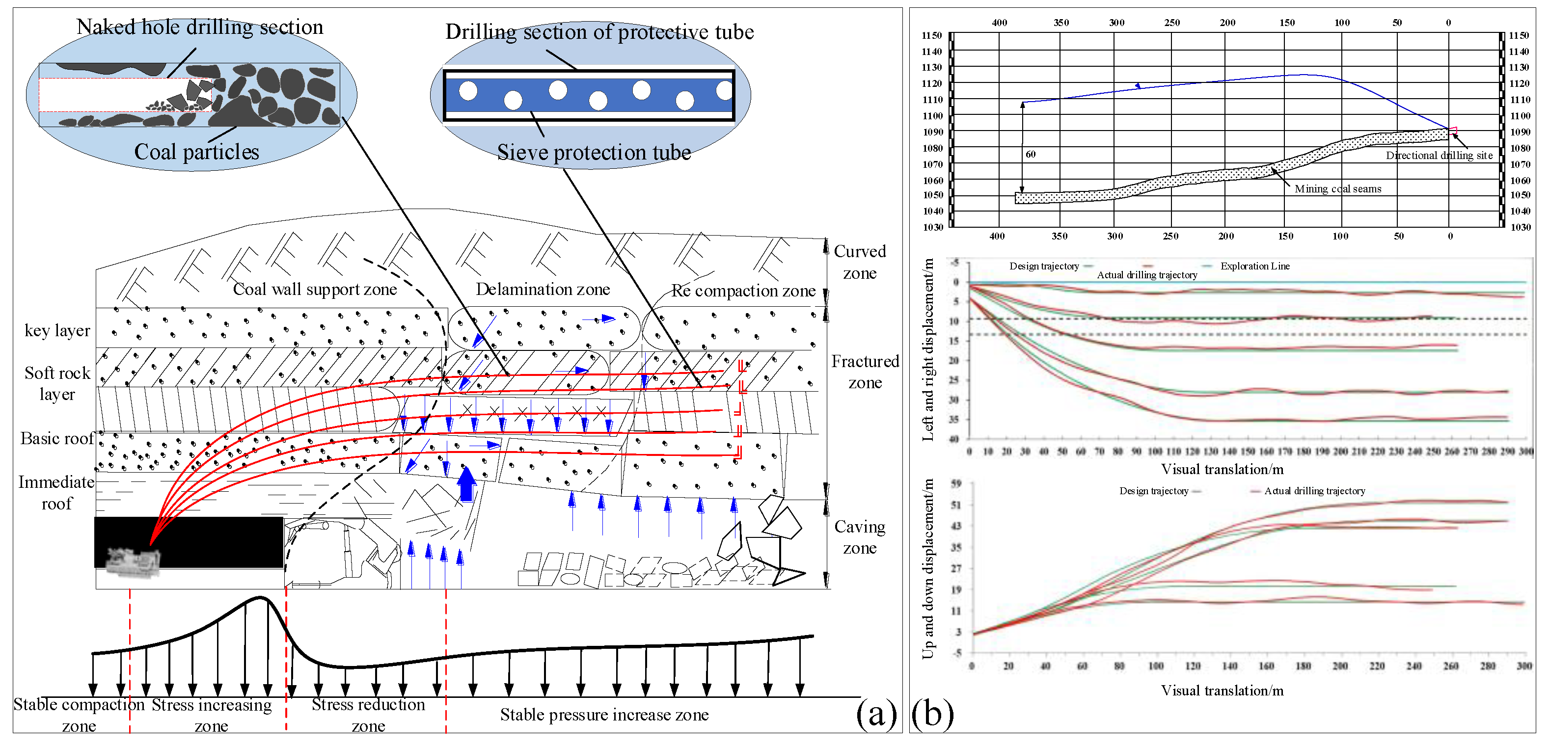
Figure 2.
Stress strain curve of coal seam 21 in Xin’an Mine.
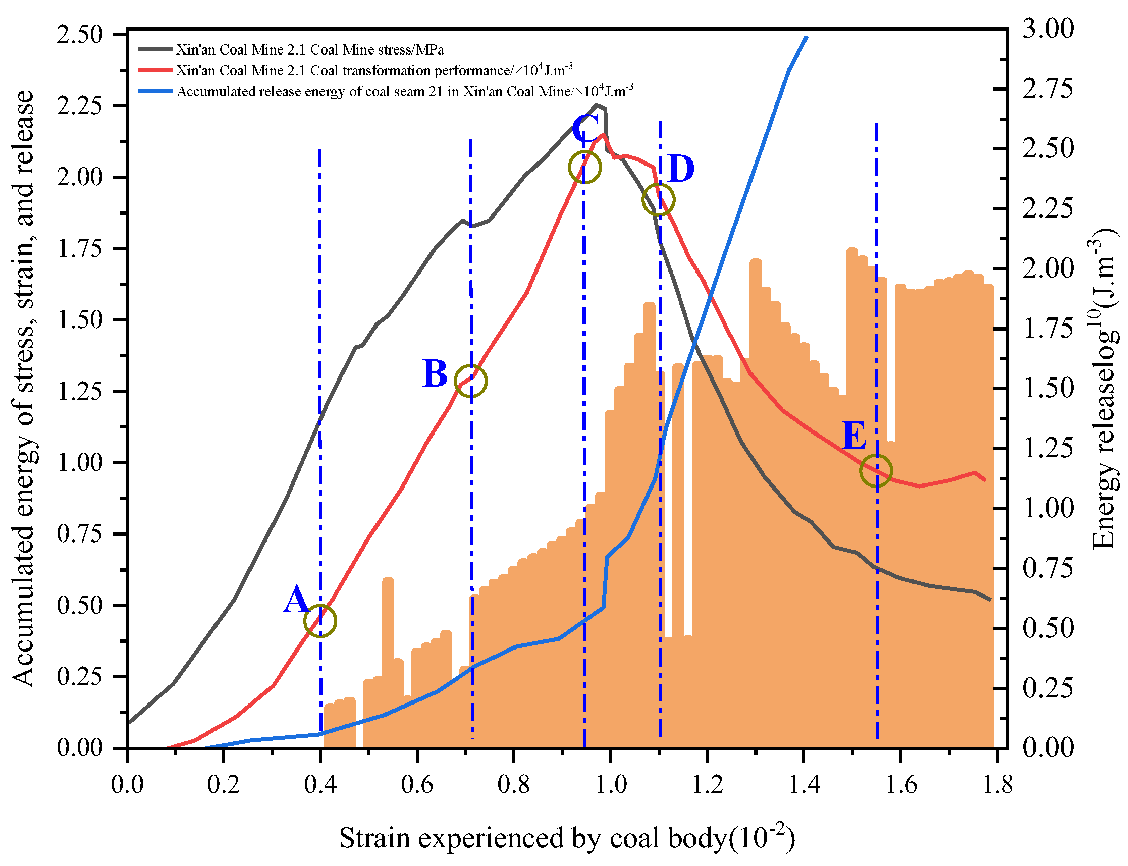
Figure 3.
Stress analysis of screen pipe.
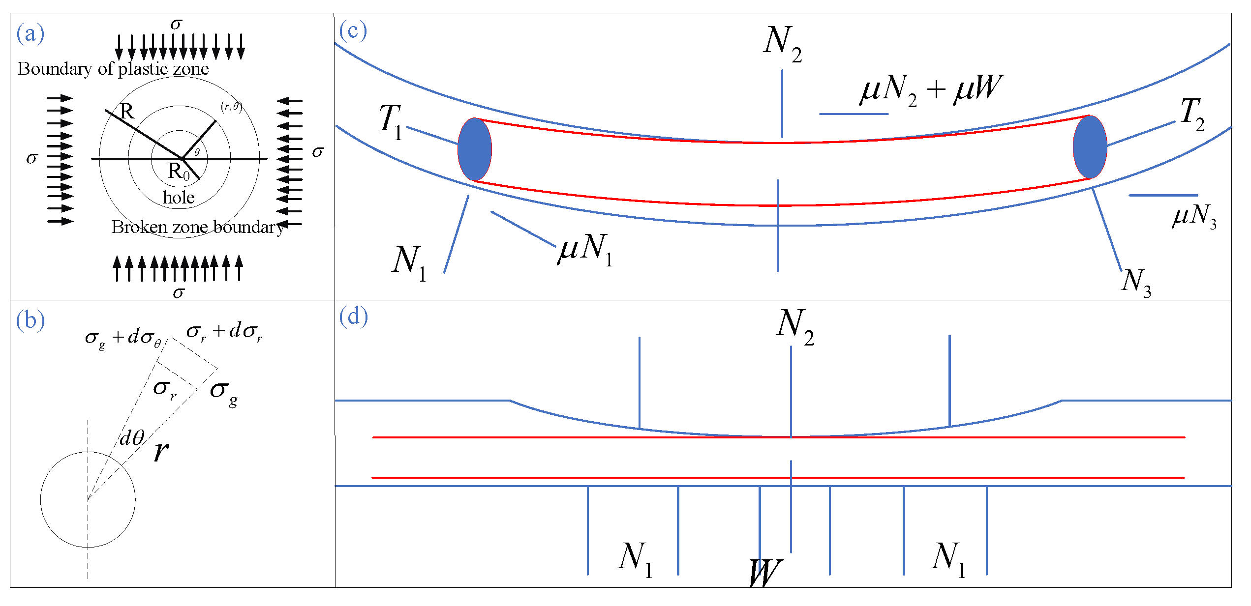
Figure 4.
Connection method and physical object of screen pipe.
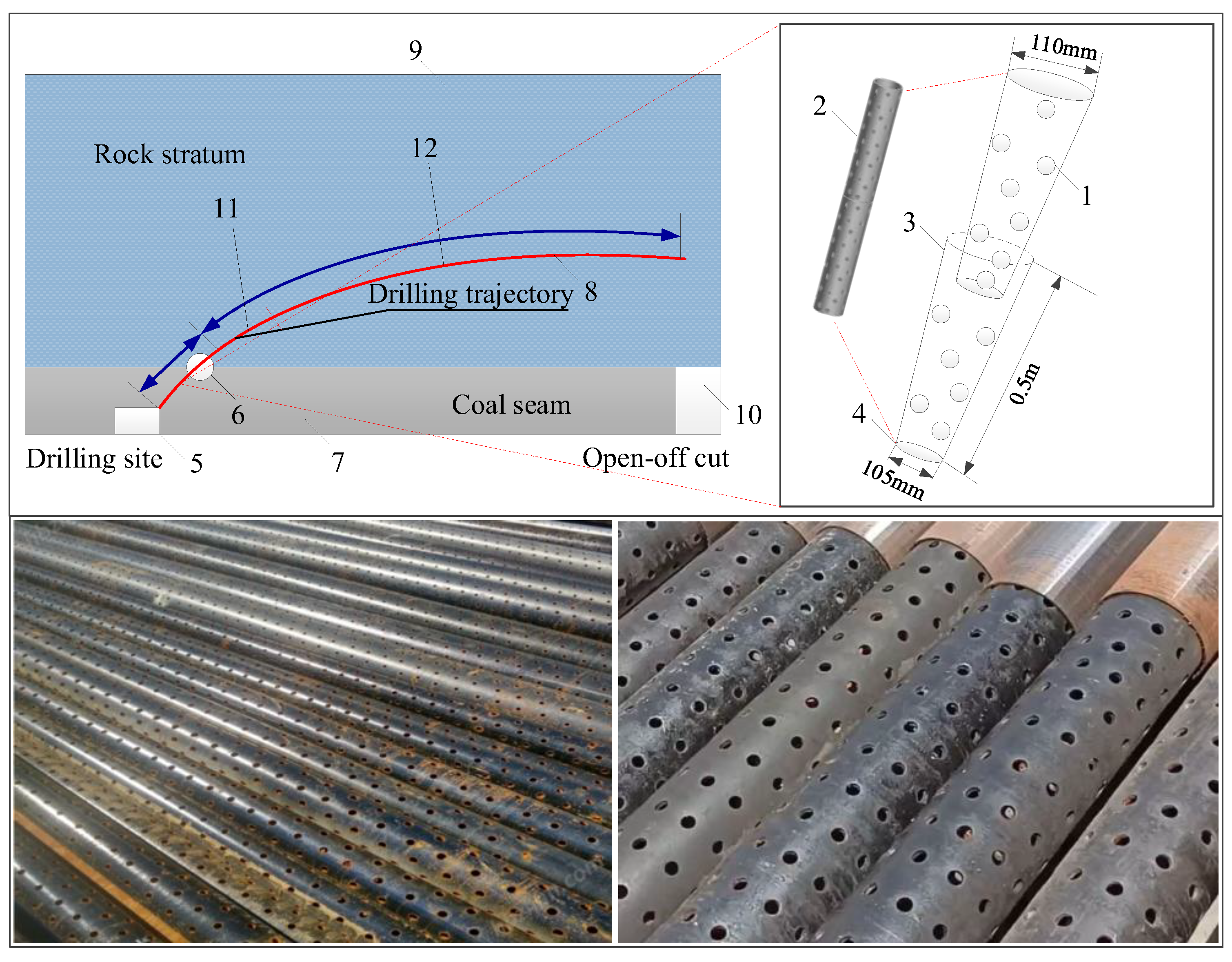
Figure 5.
Pressure distribution of high-level roof borehole at different extraction times.
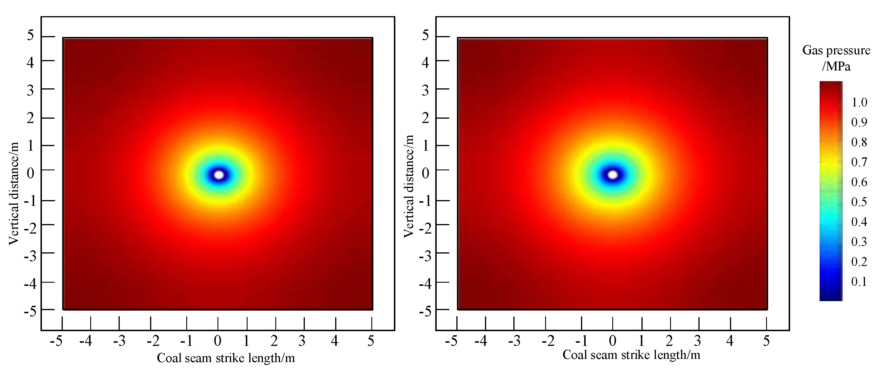
Figure 6.
Dynamic changes of gas pressure in fracture zones under different extraction times.
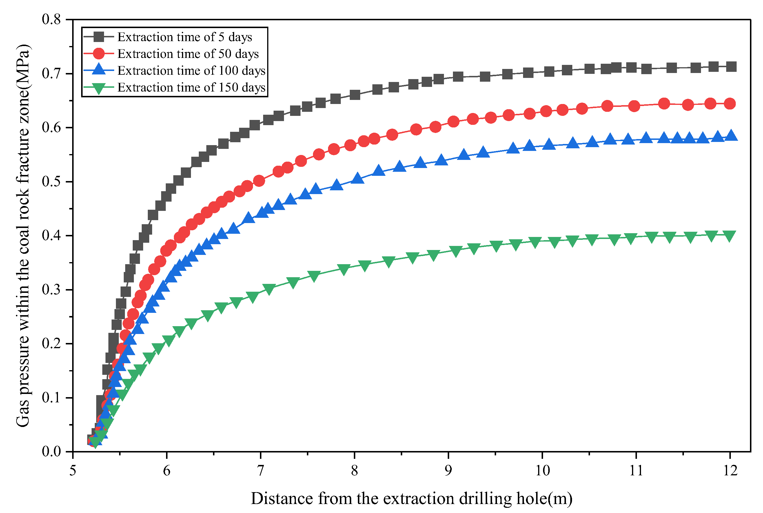
Figure 7.
Directional high-level roof boreholes measured trajectory and detector.
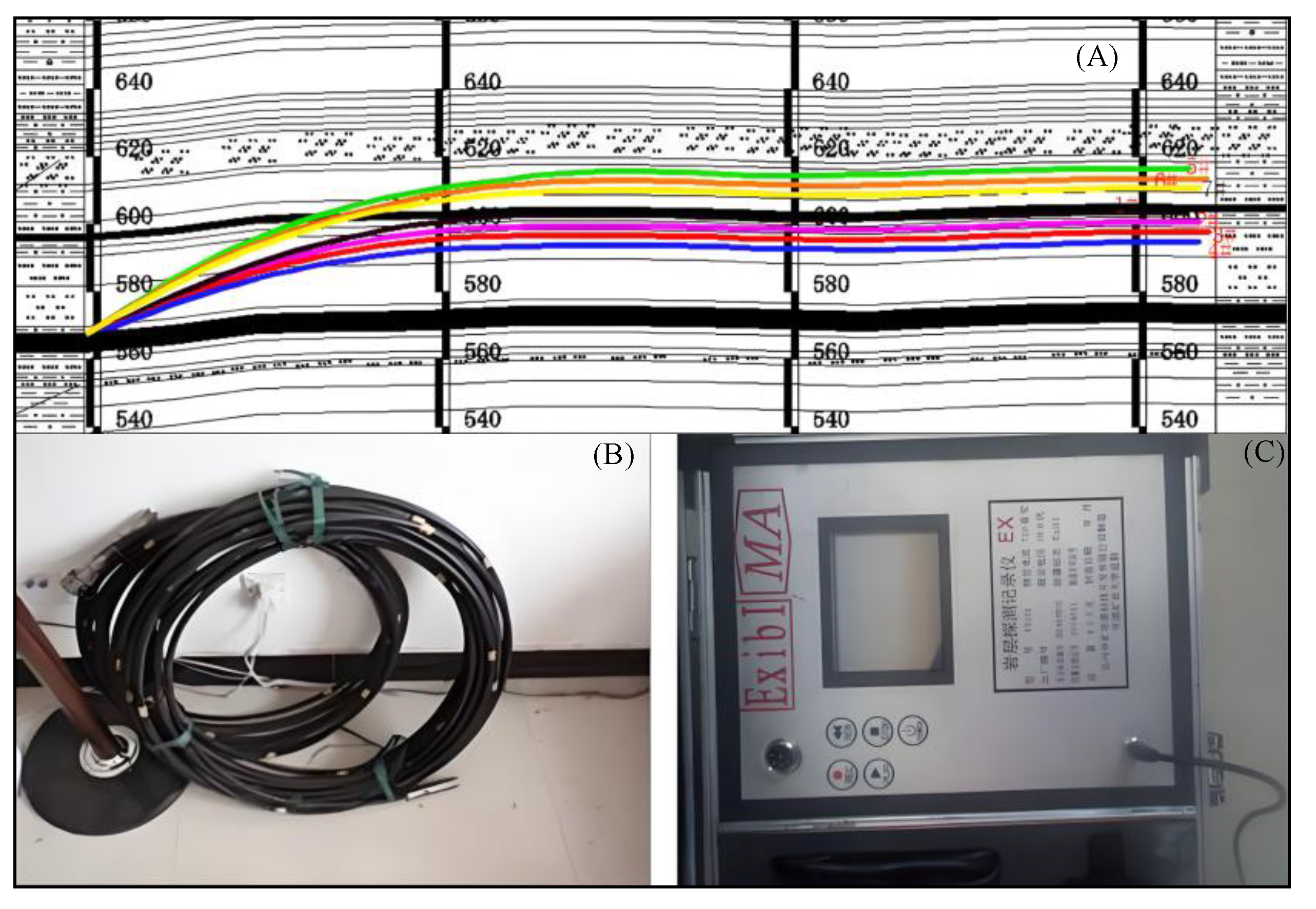
Figure 8.
Internal conditions of borehole walls at different locations during drilling.
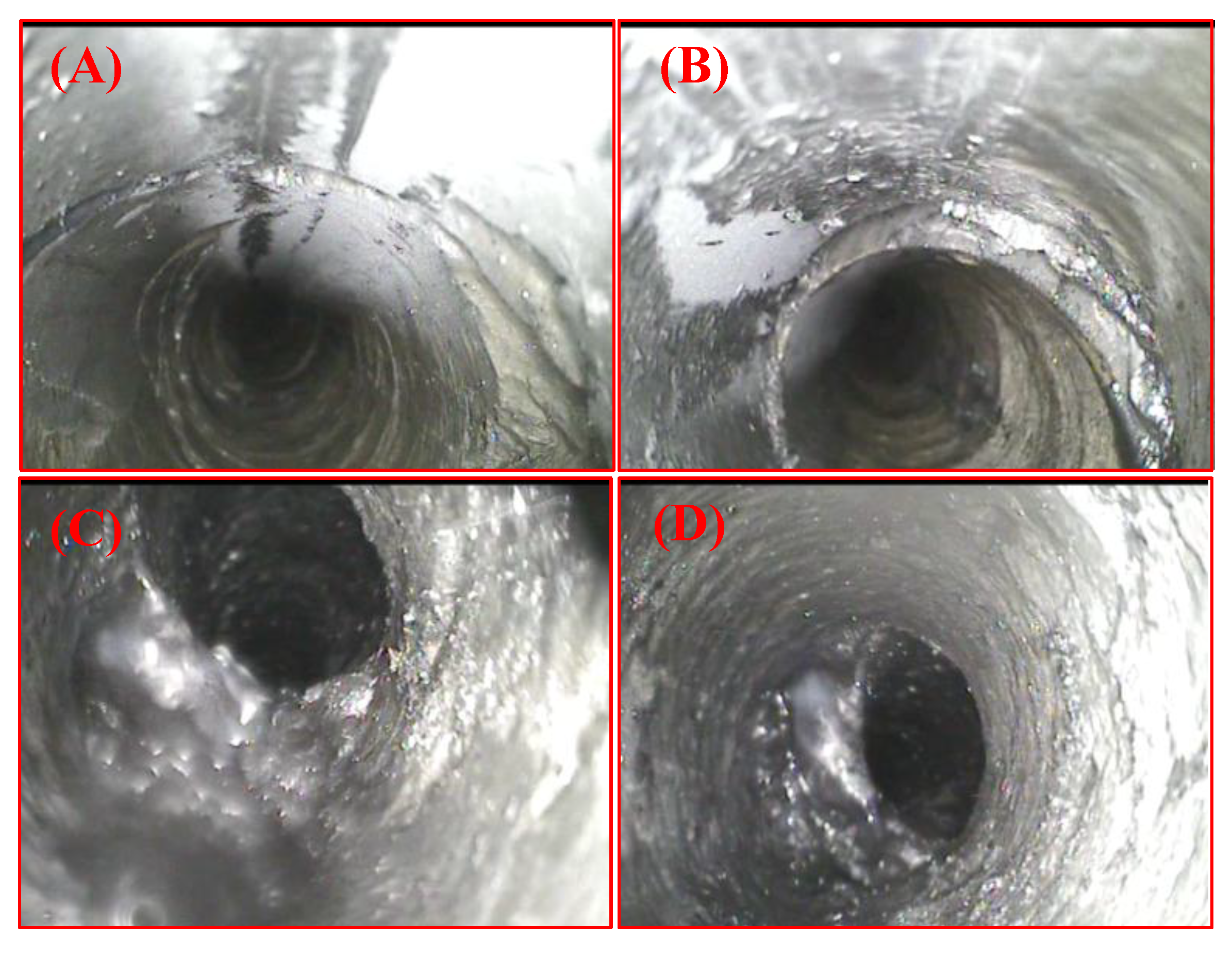
Figure 9.
Comparison of production data between workfaces with and without protective boreholes.
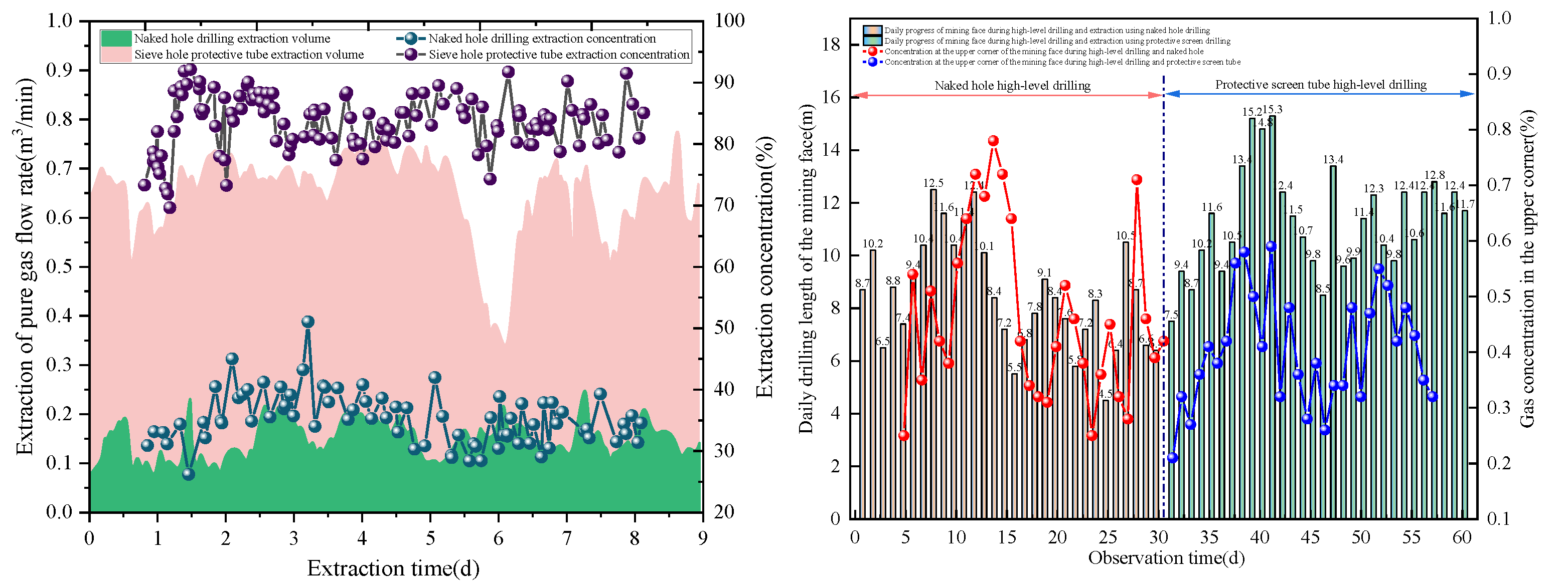

Table 1.
Production parameters of screen pipe.
| screen pipe production parameters/mm | Strength of screen pipe/MPa | |||
| Upper port diameter | Lower port diameter | Wall thickness of protective hole tube | Screen pipe size | Resistance to internal pressure |
| 110 | 105 | 7 | 6-8 | 38 |
Table 2.
Mechanical parameters of coal and rock in the 21st coal seam of Xin’an Coal Mine.
| Parameter | Value | Parameter | Value |
| Gas adsorption pressure pL(MPa) | 1.98 | Langmuir constant mL/g | 0.06 |
| Klinkenberg coefficient | 1.44 | Gas adsorption strain εL | 0.10 |
| Rock density ρ(kg/m³) | 2550 | Fracture compressibility Cf | 0.0024 |
| Rock Poisson’s ratio v | 0.3 | Initial gas pressure p0 | 1.03MPa |
| Rock matrix elastic modulus Em(GPa) | 5.323 | Molar volume of methane at standard conditions Vm [L/mol] | 22.4 |
| Initial rock fracture porosity ϕf0 | 0.02 | Gas constant R[J/mol/K] | 8.413 |
| Initial matrix porosity ϕm0 | 0.045 | Gas extraction time t | 600 |
| Initial fracture permeability η0(m²) | 2.1×10⁻¹⁶ | Time delay d | 0.12 |
| Jump coefficient η | 200.96 | Damage coefficient λ | 0.82 |
| Initial cohesion C0(MPa) | 3.7 | Cohesion in plastic stage CR(MPa) | 0.85 |
| Internal friction angle (°) | 38 | Gas dynamic viscosity μ(Pa·s) | 1.88×10⁻⁵ |
Table 3.
Comparison of gas extraction parameters with and without protective boreholes.
Disclaimer/Publisher’s Note: The statements, opinions and data contained in all publications are solely those of the individual author(s) and contributor(s) and not of MDPI and/or the editor(s). MDPI and/or the editor(s) disclaim responsibility for any injury to people or property resulting from any ideas, methods, instructions or products referred to in the content. |
© 2026 by the authors. Licensee MDPI, Basel, Switzerland. This article is an open access article distributed under the terms and conditions of the Creative Commons Attribution (CC BY) license (http://creativecommons.org/licenses/by/4.0/).
Copyright: This open access article is published under a Creative Commons CC BY 4.0 license, which permit the free download, distribution, and reuse, provided that the author and preprint are cited in any reuse.


