
Submitted:
21 June 2025
Posted:
23 June 2025
You are already at the latest version
Abstract
Disaster prevention and control of thick and hard roof breakage in longwall mining is a major technical problem faced by coal production enterprises. Taking 15311-south workings face of a mine as the engineering background, a mechanical model of thick and hard roof breakage in longwall workings was established to analyze the main influencing factors of the energy released by the initial and cyclical breakage of thick and hard roofs and the disaster-causing mechanism. The results show that the total energy released from hard roof breakage is positively correlated with the mining thickness, hard roof thickness, hard roof tensile strength and negatively correlated with the direct roof thickness, and the total energy released from the initial breakage of the main roof, is more than twice as much as that released from the cyclic breakage. Based on the production geological conditions, the parameters of directional long-drilling fracturing of thick-hard roof (fine sandstone) in 15311-south working face were determined as follows: single-point water injection volume of 20m3, spacing of fracturing points of 15m. Based on the control idea of “energy mitigation - structural weakening - stress regulation”, the “fixed-length drilling - hydraulic fracturing of thick-hard roof” was proposed. Based on the idea of “energy mitigation, structural weakening and stress control”, the three-dimensional fracturing technology of “fixed-length drilling, segmental fracturing and layered control” was applied in the field practice. On-site monitoring shows that: the maximum amount of coal pillar gangs moving in 15311-south tailgate is 236mm, the maximum amount of solid coal moving is 135mm, and the maximum value of roof and floor convergence is 287mm; the initial pressure step of the working face is reduced from 45m to 18m; compared with the non-fractured working face, the average reduction of the cycle pressure step of the quarry is 35%, and the scheme effectively ensures the safe and efficient mining of the comprehensive workface under the thick-hard roof.
Keywords:
Extra-thick coal seams
; Thick-hard roof
; Fully-mechanized top coal caving mining
; Large-section mining space
; Directional hydraulic fracture
1. Introduction
Under the background of large-scale and high-intensity integrated mining of longwall, how to achieve safe and efficient advancement of longwall working face under the thick-hard roof has become a common technical problem faced by global mining field [1,2]. According to statistics, in the recoverable reserves of thick coal seams in China, the proportion of the uniaxial compressive strength of the roof rock strata exceeding 60 MPa reaches 37%, corresponding to the number of longwall workings more than 1,200, which are mainly distributed in large-scale production mines, such as Datong in Shanxi, Shaanxi and Mongolia, etc. [3]. Due to good integrity, high strength and strong self-stabilisation ability, such hard roofs are prone to form large overhanging roofs in the open area during the advancement of longwall workings, and their hazards are strongly coupled with geological conditions and mining parameters [4,5]. Relevant studies have shown that when the length of suspended roof exceeds 1/3 of the working face length, the elastic strain energy accumulated in the roof plate can reach the order of 10⁹J, and the risk of inducing dynamic hazards such as impact ground pressure and hurricane effect increases significantly [6]. In addition, the convergence and closure rate of the roadway triggered by the overhanging roof of thick hard top plate can be up to 3~5 times of the conventional geological conditions, and the rate of hydraulic bracket crushing and destruction is elevated to 22%~35%, which has become a key bottleneck restricting the safe and efficient mining of underground longwall of coal [7,8].
Researchers at home and abroad have used multiple means to carry out in-depth research on the mechanism of hard roof disaster and its control technology and achieved good results in field application. Dou et al [9] based on the principle of static and dynamic load superposition, analyzed the mechanism of impact pressure prevention and control of hard top plate, and put forward time-sharing, zoning, and grading of broken roof blasting prevention and control technology. Based on the concept of large space quarry, Yu et al [10] revealed the breaking mechanism of hard top plate in near and far field, and proposed the integrated hydraulic fracturing joint prevention and control technology in Datong mine area in China, which has achieved good engineering verification. Kang et al [11] established a fracture network evolution model for hydraulic fracturing of thick hard sandstone roof based on the fracture expansion energy criterion, and put forward the process of ‘graded pressure boosting-directional injection’, which shortened the step interval of the roof cycle from 32 m to 16 m. Zhao et al [12] obtained the results of the inversion results based on the microseismic CT. When the spacing of fracturing sections is >50m, the connectivity of fracture network is less than 60%, which leads to the ‘island effect’ in the weakened area. Based on fracture mechanics and discrete element numerical simulation, Ju et al [13] analyzed the asymmetric expansion of hydraulic fracture cracks in laminated sandstone top plate, and proposed the parameter of ‘critical stress difference ratio’ for predicting the direction of hydraulic fracture expansion. Based on the three-point bending experiment of half disc and theoretical fracture mechanics analysis, Zhao Shankun et al [14] investigated the influence of cutting angle on the expansion direction of hydraulic fracturing cracks in the roof plate, which provided powerful data for the time of hydraulic fracturing and anti-punching in hard roof plate.
The above studies provide a reliable theoretical basis and technical reference for the mechanism and control of the disaster caused by the overhanging roof under the thick and hard roof slab. However, in the past, there were obvious errors in the design of directional hydraulic fracturing parameters for hard rock formations. Specifically, the spacing of fracture points and the extension range were mostly determined based on on-site experience or laboratory methods, or the strength reduction method was used for the engineering scale modelling analysis of the control effect of hydraulic fracturing on the top plate, and the numerical computation model on engineering scale was lacking in order to assess the extent of the weakening of the hard top plate and the effect of top plate weakening in the process of quarrying in detail. There is a lack of engineering-scale numerical models to assess in detail the degree of hard roof weakening by hydraulic fracturing and the effect of roof weakening during mining.
In view of this, this paper establishes a mechanical model of the hard roof in a longwall quarry using the 15311-south workings of a mine as the engineering background, derives an analytical solution for the mechanics of the total energy released from the fracture of the hard roof, and carries out a sensitivity analysis of its influencing factors. Based on the principles of reducing the overhanging roof length of the quarry and lowering the energy released from the breaking of the hard top plate, the proposed hydraulic fracturing control technology with fixed-length drilling holes for thick and hard top plate has achieved good engineering practice in the research site, and is of good significance as a guide in the field.
2. Case Study
Xinjiang Coking Coal Group 1890 Coal Mine, located within Dabancheng District, Urumqi City, is situated approximately 130 km north of Urumqi City, as shown in Figure 1(a). The mine has an annual production capacity of 1.20 Mt/a. Within the mine field, the coal seams are primarily concentrated in the Lower Jurassic Badaowan Formation, containing a total of 12 minable coal seams. The current production area is the first level third mining district, which operates one coal mining face and two development headings. The 15311 south working face is located within the first level third mining district. It is bounded by the outcrop line of the 5# coal seam to the east, the 15312 working face to the west, the southern mine field boundary protective coal pillar to the south, and the 1901 east small shaft and 1901 west small shaft to the northeast. The 15311 south working face has an average dip length of 275 m and an average strike length of 988 m, as shown in Figure 1(c). The main mining target is the 5# coal seam, with an average minable thickness of 27.15 m and an average dip angle of 2°. The lithology of the seam roof, from bottom to top, consists sequentially of sandy mudstone, fine sandstone, carbonaceous mudstone (or coaly shale), sandy mudstone, and fine sandstone. A comprehensive columnar section of the roof and floor strata is shown in Figure 1(b). In-situ uniaxial compressive strength tests on the roof strata above the coal seam were conducted using a WQCZ-56 in-situ rock strength tester. The test results are shown in Figure 1(d). The borehole was positioned perpendicular to the roof of the 15311 south working face haulage roadway, with a depth of 50 m. The vicinity of the borehole collar corresponds to the 5# coal seam, where the compressive strength ranges between 22~32 MPa. The peak strength of the fine sandstone roof beyond 35 m from the collar exceeds 70 MPa, classifying it as a hard rock layer.
The currently mined 5# coal seam at the 1890 Coal Mine of Xinjiang Coking Coal Group is overlain by a unique multi-layered hard roof strata structure, exhibiting intense ground pressure characteristics typical of thick, hard, and difficult-to-cave roof strata. Affected by this intense ground pressure, the surrounding rock of the 15311 South Working Face roadway has suffered severe deformation and damage. This is primarily manifested as intense floor heave driving “inverted trapezoidal” convergence in both ribs, with convergence typically exceeding 1.0m. Influenced by the multi-layered hard roof structure, the surrounding rock periodically exhibits dynamic failure characterized by “sudden displacement”, leading to surrounding rock instability and extensive failure of the support structure. The characteristics of the roadway deformation and damage are shown in Figure 2.
3. Thick and Hard Overhanging Roof Effect in Longwall Quarries and Its Disaster-Causing Mechanism
3.1. Suspended Roof Effect of Thick-Hard Main Roof
During the advancement of the longwall working face, the soft direct top (or top coal) is generally able to collapse in time in the mining void area due to the low strength of the rock strata and the development of joints and fissures under the coupling effect of mining stress and self-weight. Due to the high strength and good integrity of the thick hard top plate, it is difficult to slide down in time under the action of the overlying rock layer and self-weight, forming a large area of overhanging top in the mining hollow area. With the further advance of the working face, the overhanging basic top bending moment reaches its limit state to form O-X cycle breakage, as shown in Figure 3.
Due to its high strength and good integrity, a large amount of elastic strain energy is accumulated inside the thick hard roof before breaking, and the strain energy is suddenly released after its rupture, which seriously threatens the safety of mining equipment and operators. Suspended roof disaster presents a three-stage evolution characteristic of “energy accumulation - structural instability - power release”, as shown in Figure 4.
3.2. Disaster Mechanism of Thick Hard-Suspension Roof Breakage
The study shows that as the working face advances, the thick hard roof plate breaks and releases energy to form a dynamic shock wave in the overhanging roof of the mining hollow area, which is dynamically transmitted to the vicinity of the working face and superimposed with the high static load of the coal and rock body, further inducing the impact ground pressure disaster. Therefore, it is necessary to establish a mechanical model of thick and hard roof breakage as shown in Figure 5 to analyze the energy accumulation characteristics of thick and hard roof and its influencing factors, so as to provide theoretical support and data support for the management of hard and hard overhanging roof disaster.
According to the relevant principles of material mechanics, without considering the difference in the length direction of the working surface, the thick-hard roof before the initial breakage can be simplified as a solidly supported beam structure with unit width, and the thick-hard roof before the cycle breakage can be simplified as a cantilever beam structure with unit width. The bending moment M1(x) on any cross-section of the thick-hard roof before initial breakage, and the bending moment M2(x) on any cross-section of the thick-hard roof before cyclic breakage, can be expressed as:
In the formula (1), l1 is the initial breaking step of the thick-hard roof, m; l2 is the cycle breaking step of the thick-hard roof, m; q0 is the overlying load of the thick-hard roof, N/m.
With the tensile strength as its breaking limit, the initial breaking step l1 and cycle breaking step l2 of the thick-hard roof are calculated by the following formula:
In the formula (2), h2 is the thickness of thick-hard roof, m; Rt is the tensile strength of thick-hard roof, MPa.
According to the relevant principles of elastic mechanics, the thick-hard roof is regarded as an elastic rock beam, and its bending strain energy U before breaking can be expressed as:
In the formula (3), E is the modulus of elasticity of the thick-hard roof, GPa; I is the moment of inertia per unit width of the thick-hard roof beam section, I = h2 2/12.
Substituting the formula (1) into the formula (2), the bending strain energy released by the initial breaking and cyclic breaking of the thick-hard roof can be obtained as:
In the formula (4), U11 and U21 are the bending strain energy released by the initial and cyclic breakage of the thick-hard roof, respectively, kJ.
The rotational kinetic energy U12 and U22 brought by the initial and cyclic breakage of the thick-hard roof and its overlying loaded rock layer with its common movement are respectively:
In the formula (5), g is the acceleration of gravity, N/kg; ρ2 and ρ3i are the densities of thick-hard roof and overlying load layer, kg/m3; h3i is the thickness of load layer of thick-hard roof, m; n is the number of load layers of thick-hard roof; α and β are the slewing angle of the hard rock layer after the initial breakage and cyclic breakage, °, respectively.
According to the theory of mine pressure and rock layer control, the slewing angle α and β after breaking the thick-hard roof can be obtained from the formula (6):
In the formula (6), k is the direct top breaking coefficient; ρ2 and ρ3i are the densities of the thick-hard roof and the overlying load layer, respectively, kg/m3; h1 is the thickness of the direct top, m; m is the thickness of the coal seam mined, m. The total energy released after the initial breaking of the thick-hard roof and the cycle breaking of the load layer is as follows.
From the above analyses, it can be seen that the total energy released after the initial breakage of the thick-hard roof and the cyclic breakage and the load layer after the coordinated slewing and stabilisation of the thick-hard roof are respectively:
From the formula (7), it can be seen that the total energy released after the hard roof breakage is closely related to the thickness of hard roof h2, the modulus of elasticity of hard roof E, the fracture step of hard roof l1 and l2, the overburden load of hard roof q0, the mining thickness of the coal seam m, the thickness of the direct roof h1, and the coefficient of expansion of the direct roof k. The higher the total energy released by the breakage of hard rock layer is, the greater the energy of dynamic load stress wave transmitted to the working face is, and the greater the risk of impact damage to the working face is.
The higher the total energy released by the fracture of hard rock layer, the higher the energy of the dynamic load stress wave transmitted to the working face, and the higher the risk of impact damage to the working face. When it reaches the index of its impact instability, the working face will be very likely to produce strong impact ground pressure, which will cause equipment damage and casualties in serious cases, as shown in Figure 6.
3.3. Analysis of Influencing Factors and Impact Mechanisms on Total Energy Release During Thick-Hard Roof Fracture
Based on the laboratory test, working face production geological conditions and field measurement results, it is determined that the selection results of relevant parameters are shown in Table 1. Substituting the relevant parameters into the formula (2), it can be obtained that the initial breakage step l1 of the thick-hard roof of the 15311-south working face is 60.14m, and the cycle breakage step l2 is 24.55m.
Using the single control variable method, sensitivity analyses were carried out on the influence patterns of different factors on the total energy released after breaking the thick-hard roof, as shown in Figure 7 and Figure 8.
(1) From Figure 7 and Figure 8, it can be seen that the total energy released by the thick-hard roof breaking is positively correlated with the mining thickness of the coal seam, the thickness of the thick-hard roof, and the tensile strength of the thick-hard roof, and negatively correlated with the thickness of the immediate roof; under the same geological background, the total energy released by the initial breakage of the main roof is more than twice of that released by the cyclic breakage of the main roof.
(2) The larger the thickness of the thick-hard roof is, the higher the elastic strain energy accumulated by its bending deformation is; the higher the tensile strength is, the larger the initial and cyclic breakage are, and the higher the total energy released by the breakage of the unit width of the hanging roof.
(3) The smaller the immediate roof thickness and the larger the coal seam mining thickness, the lower the filling degree of direct roof collapsing and swelling in the mining area, the larger the slewing angle of the thick-hard roof after its initial and cyclic breaking, and the higher the slewing kinetic energy released by its slewing and stabilisation with the overlying load.
(4) In addition, the larger the thickness of the immediate roof is, the farther the thick-hard rock breakage location is from the working face, the larger the attenuation amount of the dynamic load stress wave generated by the breakage is transmitted to the vicinity of the working face, and the lower the risk of the working face generating impact ground pressure;
In the process of engineering practice, hydraulic fracturing and other measures can be taken to weaken the integrity of the internal structure of the hard rock layer, prompting it to collapse in the hollow area in time after the workface is mined back to reduce the degree of its suspended roof, so that part of the elastic strain energy can be released slowly and gradually and safely, avoiding the impact triggered by the sudden large-scale fracture of the roof plate to focus on the release of high-energy. In addition, corresponding water injection and softening measures can be taken for the weakened roof plate below to improve its risk release and crushing degree, and to improve its filling degree in the extraction zone. It not only reduces the slewing space of the thick-hard roof breakage, but also improves the attenuation coefficient of the dynamic load stress wave formed by the breakage of the thick-hard roof in the soft and weak rock layer below.
4. Field Practice of Hydraulic Fracturing in Fixed-Length Boreholes
4.1. Principles of Hydraulic Fracturing with Fixed-Length Drilling
Firstly, after completing the directional drilling construction using a directional drilling rig and feeding the fracturing tool string into the designated location, the target layer section was fractured by single card fracturing through double packers, and then the high-pressure pump was activated, and when the high-pressure water reached the start-up pressure of the rear packers, the sealing space was formed between the packers. Continuing to increase the pumping pressure, the high-pressure water is continuously injected into the sealing space, prompting the water pressure acting on the borehole wall to gradually increase, and when the water pressure in the sealing space is greater than the fracture pressure of the rock formation, rupture cracks will be produced along the borehole wall, destroying the integrity of the rock formation as a whole. After completing the first fracturing construction, the high-pressure pump is turned off, and the packer is automatically restored to its original size; the directional drilling rig is used to drag the packer to the next position of the design to carry out the second fracturing construction, and the fracturing construction of the designed construction section is completed in turn, and the adjacent fracturing sections form three-dimensional three-dimensional continuity of the rock formation cracks. The process flow of hydraulic fracturing with fixed-length drilling is shown in Figure 9.
4.2. Hydraulic Fracturing Top Cutting and Pressure Relief Program
Comprehensive theoretical calculations, numerical simulation results, production geological conditions of the working face as well as fracturing parameter design principles, according to the recoverable length of the 15311-south working face, it is determined that the technical scheme of hydraulic fracturing with fixed-length drilling holes for the 15311-south working face is shown in Figure 10, and the technical parameters of the directional drilling holes are shown in Table 3.
(1) According to the actual production conditions, a total of 1# drilling site and 2# drilling site are arranged, which are located in the backwind link of 15311-south intake roadway (H1, H2, L1, L2, L3, M1, M2 drilling holes) and in 15312 tailgate (H3, H4, L4, L5, L6) respectively.
(2) According to the rock layer histogram, it was determined that the fixed-length drill holes were divided into three layers: 6m, 15m and 48m positions above the roof of the roadway.
(3) The diameter of the drill holes is 120 mm, and there are 4 high level drill holes (48m level) (H1, H2, H3, H4) located in the middle of fine sandstone of the main roof; 6 low level drill holes (15m level) (L1, L2, L3, L4, L5, L6) located in the gangue position of the coal seam; and there are 2 supplemental holes (6m level) in the shadow area of the turning radius of the fixed-length drill holes (M1, M2).
(4) H-type drilling design feed 2772m, drilling influence range for 15311-south intake roadway to the working face direction of 50 ~ 210m, spacing 50m; L-type drilling design feed 4134m, drilling influence range for 15312 tailgate to the working face direction of 30 ~ 230m, spacing 40m; M-type drilling design feed 315m, drilling control 15312 tailgate to the working face direction of 106 ~ 131m, spacing of drilling. 131m, the spacing of the drill holes is 25m, and the final position of the drill holes crosses the stopping line by 20m.
(5) The spacing of drilling holes is 1.0m, the height of drilling holes is controlled at 1.8~2.0m from the bottom plate, the azimuth angle of drilling holes is controlled within the range of ±3° in the design requirements, and the inclination angle is controlled within the range of ±1° in the design requirements, avoiding the influence of the anchor rods and anchor cables.
(6) According to the numerical simulation results and engineering experience, backward segmental fracturing method is adopted to carry out segmental fracturing in a single borehole, and the spacing of fracturing points in the borehole is 15m.
4.3. Hydraulic Fracturing Field Application Results
(1) Drill hole peeping in hard-top fractures
The internal integrity of the fractured borehole was analyzed using borehole imaging equipment, as shown in Figure 11. The through-fracture was produced along the borehole axis near the fracturing point, and localized circumferential fissures were generated, which significantly reduced the integrity of the thick-hard roof (fine sandstone). As the working face advances, it is capable of collapsing rapidly into the void zone under the action of the overlying rock load and the hysteresis stress in the void zone.
(2) Water injection pressure monitoring for fracturing in sections
Using the pressure monitoring equipment of the high-pressure water injection system, real-time tracking of the water injection pressure during the segmental fracturing process of the fixed-length borehole is carried out. Taking borehole H2 as an example, the water injection pressure curves at different fracturing stages are shown in Figure 12.
During the initial fracturing of each section of borehole H2, the water injection pressure showed fluctuation phenomenon when the pressure reached about 3 MPa, which was caused by the continuous injection of high-pressure water into the sealer and the expansion of the sealer. Subsequently, the water injection pressure increased sharply and then continued to decrease, which indicated that the high-pressure water was continuously injected into the sealing interval between the packers at both ends, and the water pressure in the sealing interval increased to the fracturing pressure of the rock body, and the rock body on the surface of the borehole ruptured.
When the water injection pressure showed sawtooth-like fluctuations, it indicated that the water injection pressure entered the pressure preservation stage, and the hydraulic fractures continued to expand to the depth; the presence of multiple pressure drops during the injection period indicated that the continuous injection of high-pressure water induced the further rupture of the rock body in the deep part, and the hydraulic fractures expanded deeper away from the surface of the borehole, forming a network of penetrating cracks and dense hydraulic fractures, which achieved the effect of pre-fracturing.
In addition, the fracture initiation pressure, the water injection pressure and the number of pressure drops during the first stage of fracturing were greater than those in the second stage. This indicates that the hydraulic fracture extension range produced by the first fracturing section is larger than the spacing between the two fracturing points, effectively weakening the hard top plate integrity in the control range of the second fracturing section, and the two fracturing control ranges overlap with each other, which further improves the control effect of hydraulic fracturing in directional long-distance drilling.
(3) Stress and deformation of roadway peripheral rock
A monitoring station was established every 50m in the 15311-south tailgate, and the station layout is shown in Figure 13(a). During the face mining period, the surface displacement of the surrounding rock and the evolution of coal body stress in the 15311-south tailgate are shown in Figure 13(b). The deformation of the coal pillar gangs in the roadway started to increase at about 70m from the working face, the maximum amount of coal pillar gangs moving closer is 236mm, the maximum amount of solid coal gangs moving closer is 135mm, the maximum amount of top and bottom plate convergence is 287mm, and the roadway surface displacement is small enough to ensure the safe and efficient mining of the working face.
(4) Comparison of the step of pressure coming from the quarry cycle
Figure 14 shows the comparison of the working resistance of hydraulic support in 15311-south working face and the statistical results of the average coming pressure step before and after adopting hydraulic fracturing with directional long drilling.
After adopting directional long-drilling hydraulic fracturing in 15311-south working face, the initial incoming pressure step in the working face was reduced from 45m to 18m, and the incoming pressure step in the upper, middle and lower areas of the working face was reduced compared with that of the working face without hydraulic fracturing, and the average reduction of cycle incoming pressure step was 35%. This technology effectively reduces the overhanging effect of the thick-hard roof in the open area, reduces the pressure step in the quarry, and ensures the safe and efficient mining of the longwall face under the thick-hard roof.
5. Conclusions
(1) Establish the mechanical model of the thick-hard roof in the longwall face, and derive the analytical solution of the energy released after the thick-hard roof breaks. The total energy released by breaking the thick-hard roof is positively correlated with the mining thickness of the coal seam m, the thickness of the thick-hard roof, the tensile strength of the thick-hard roof, and negatively correlated with the thickness of the immediate roof; the total energy released by breaking the main roof for the first time is more than two times of the total energy released by breaking the main roof.
(2) The control technology of hydraulic fracturing in long directional drill holes and its key parameters are proposed. Engineering practice shows that hydraulic fracturing significantly reduces the integrity of the thick-hard roof; during the mining period of the working face, the maximum amount of the coal pillar in the 15311-south tailgate is 236mm, the maximum amount of the solid coal is 135mm, and the maximum amount of the roof and floor convergence is 287mm; the initial pressure step in the working face is reduced from 45m to 18m; compared with the unfractured working face, the average reduction of the cycle pressure step is 35%, which ensures the long wall under the thick-hard roof. This ensures safe and efficient mining of longwall face under the thick-hard roof.
Data Availability Statement
Data will be made available on request.
Acknowledgments
The authors sincerely appreciate the financial support received from the Xinjiang Uygur Autonomous Region Tianchi Elite Talent Innovation Leadership Program (No.2024XGYTCYC03); Urumqi City Hongshan Sci-Tech Innovation Elite Talents Youth Top Talents Program (No. B241013004); National Key Research and Development Program Young Scientists Project (No. 2024YFC2910600); the Xinjiang Uygur Autonomous Region Key R&D Project Task Special-Department and Department Linkage Project (No. 2022B01051-3) and Xinjiang Institute of Engineering Doctoral Start-up Fund (No. 2023XGYBQJ14).
Conflicts of Interest
The authors declare that there are no known competing financial interests or personal relationships that could have influenced the work reported in this paper
References
- Z.G. Zhang, L.C. Dai, H.T. Sun, et al. Study on the Spatiotemporal Dynamic Evolution Law of a Deep Thick Hard Roof and Coal Seam[J]. Processes, 2023,11(11):3173. [CrossRef]
- B.B. Chen, C.Y. Liu, B. Wang. A case study of the periodic fracture control of a thick-hard roof based on deep-hole pre-splitting blasting[J]. ENERGY EXPLORATION & EXPLOITATION, 2022, 40(1):279-301. [CrossRef]
- D. Zhang, J. Bai, R. Wang, et al. Investigation on instability mechanism and control of abandoned roadways in coal pillars recovery face: A case study[J]. Underground Space, 2025, 20:119-139. [CrossRef]
- Q.W. Bu, M. Tu, X.Y. Zhang, et al. Analysis of Energy Accumulation and Dispersion Evolution of a Thick Hard Roof and Dynamic Load Response of the Hydraulic Support in a Large Space Stope[J]. FRONTIERS IN EARTH SCIENCE, 2022, 10:884361. [CrossRef]
- D.D. Qin, Z.C. Chang, Z. Xia. Experimental study on the strain energy evolution mechanism of thick and hard sandstone roof in Xinjiang Mining Area[J]. HELIYON, 2024, 10(2):e24594. [CrossRef]
- J.L. Jia, L.W. Cao, D.J. Zhang, et al. Study on the fracture characteristics of thick-hard limestone roof and its controlling technique[J]. ENVIRONMENTAL EARTH SCIENCES,2017, 76(17):605. [CrossRef]
- Y.B. Lu, S.H. Yan, K.Y. Zhou, et al. Structural quantification of multi-thick hard roof and strong ground pressure control in large mining height stope: a case study[J]. GEOMECHANICS AND GEOPHYSICS FOR GEO-ENERGY AND GEO-RESOURCES, 2025, 11(1):56. [CrossRef]
- K. Zhong, W.Z. Chen, W.S. Zhao, et al. Monitoring and evaluation of segmented hydraulic fracturing effect in rock burst prevention on hard roof of coal mine[J]. Journal of Central South University (Science and Technology),2022, 53(7):2582-2593.
- L.M. Dou, J.L. Kan, X.W. Li, et al. Study on prevention technology of rock burst by break-tip blasting and its effect estimation[J]. Coal Science and Technology,2020,48(1):24-32.
- B. Yu, T.J. Kuang, J.X. Yang, et al. Analysis of overburden structure and evolution characteristics of hard roof mining in extremely thick coal seam[J]. Coal Science and Technology, 2023,51(1):95-104. [CrossRef]
- H.P. Kang, Y.J. Feng, Z. Zhang, et al. Hydraulic fracturing technology with directional boreholes for strata control in underground coal mines and its application[J]. Coal Science and Technology,2023,51(1):31-44. [CrossRef]
- Y. Ju, Y.M. Yang, J.L. Chen, et al. 3D reconstruction of low-permeability heterogeneous glutenites and numerical simulation of hydraulic fracturing behavior[J]. China Science Bulletin, 2016,61(1):82-93. [CrossRef]
- ZHAO Yixin, LING Chunwei, LIU Bin, et al. Fracture evolution and energy dissipation of overlying strata in shallow-buried underground mining with ultra-high working face[J]. Journal of Mining & Safety Engineering, 2021,38(1):9-18+30.
- ZHAO Shankun. Mechanism and application of force-structure cooperative prevention and control on rockburst with deep hole roof pre-blasting[J]. Journal of China Coal Society ,2021,46(11):3419-3432.
- LING Chunwei, CHEN Qingtong, GUO Wenyan, et al. Study on overlying rock fissure and energy evolution law of high intensity mining working face adjacent to gob[J]. Safety in Coal Mines,2024,55(12):48-56.
- GAO Mingshi, XU Dong, HE Yongliang, et al. Investigation on the near-far field effect of rock burst subject to the breakage of thick and hard overburden[J]. Journal of Mining & Safety Engineering, 2022,39(2):215-226.
- ZHOU Kunyou, DOU Linming, LI Jiazhuo, et al. Effect of extra-thick key strata on the static and dynamic stress of rockburst[J]. Journal of Mining & Safety Engineering, 2024,41(5):908-919.
- WANG Wanjie, GAO Fuqiang. Study of the evolution of mining-induced fractures with longwall face proceeds-insight from physical and numerical modeling[J]. Journal of Mining and Strata Control Engineering, ,2023,5(2):17-26. [CrossRef]
- Gao, Fuqiang, Stead, Doug, Kang, Hongpu, Numerical Simulation of Squeezing Failure in a Coal Mine Roadway due to Mining-Induced Stresses, Rock Mechanics and Rock Engineering.2015;48(4):1635-1645. [CrossRef]
- PANG Lining, HU Quanhong, JING Judong, et al. Regional pressure relief technology with directional hydraulic fracturing of deep buried thick hard roof working face[J]. Coal Engineering, 2023,55(10):67-73.
Figure 1.
Engineering geological conditions.
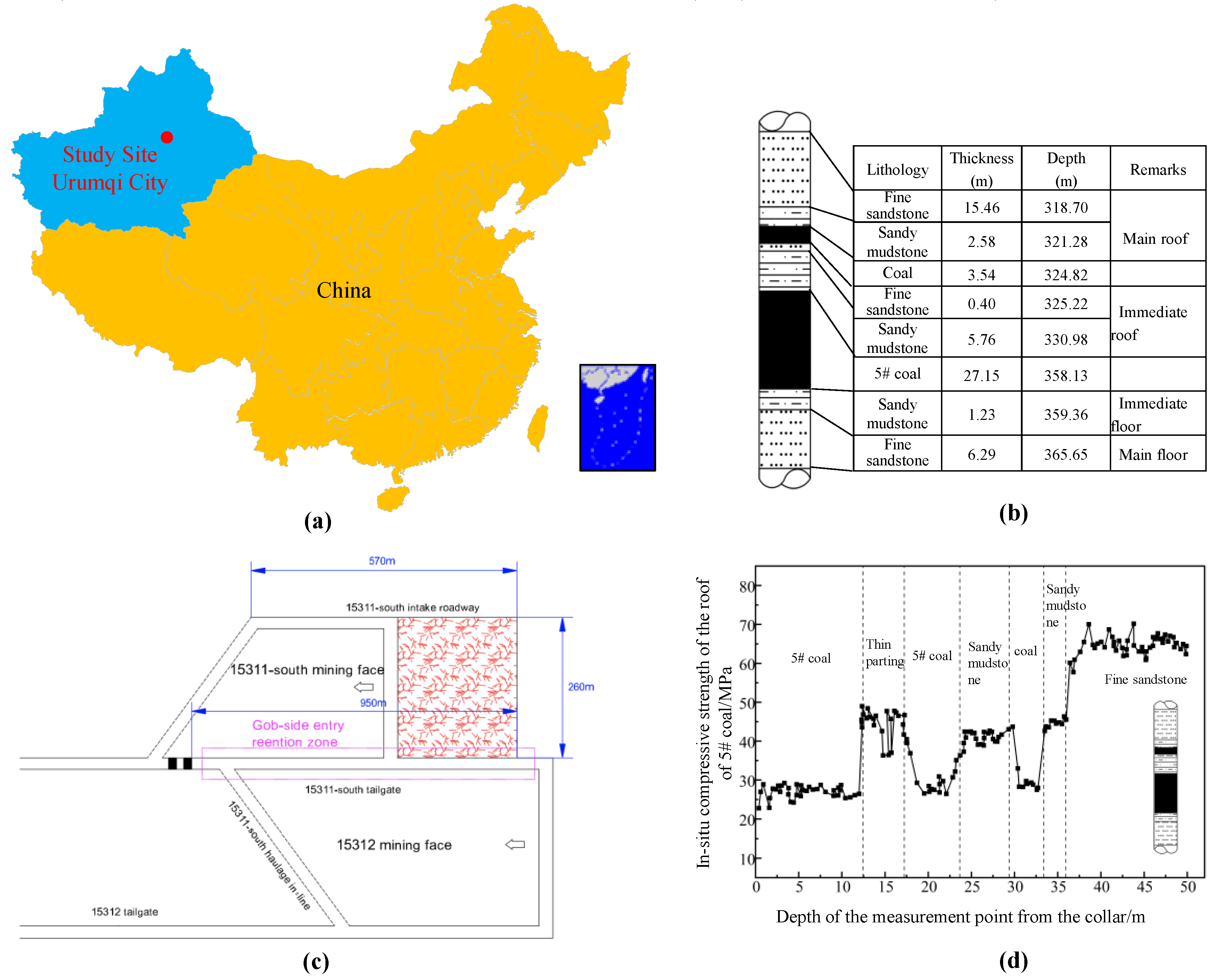
Figure 2.
The characteristics of roadway deformation and damage.
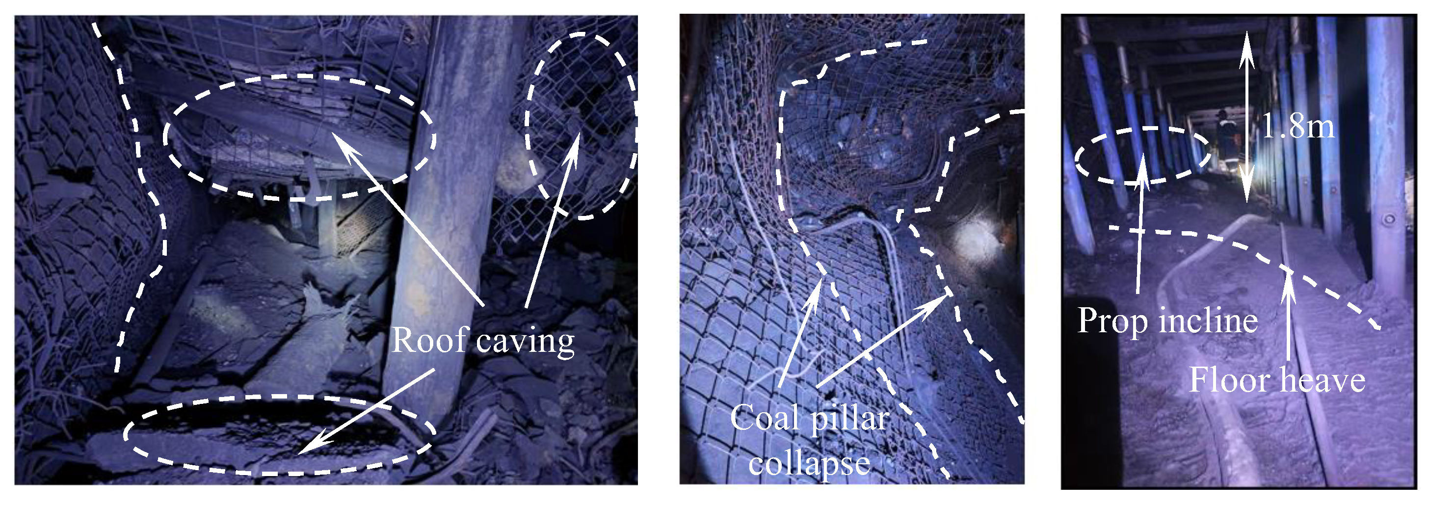
Figure 3.
Fracture characteristics of the thick-hard roof overlying the mining area.
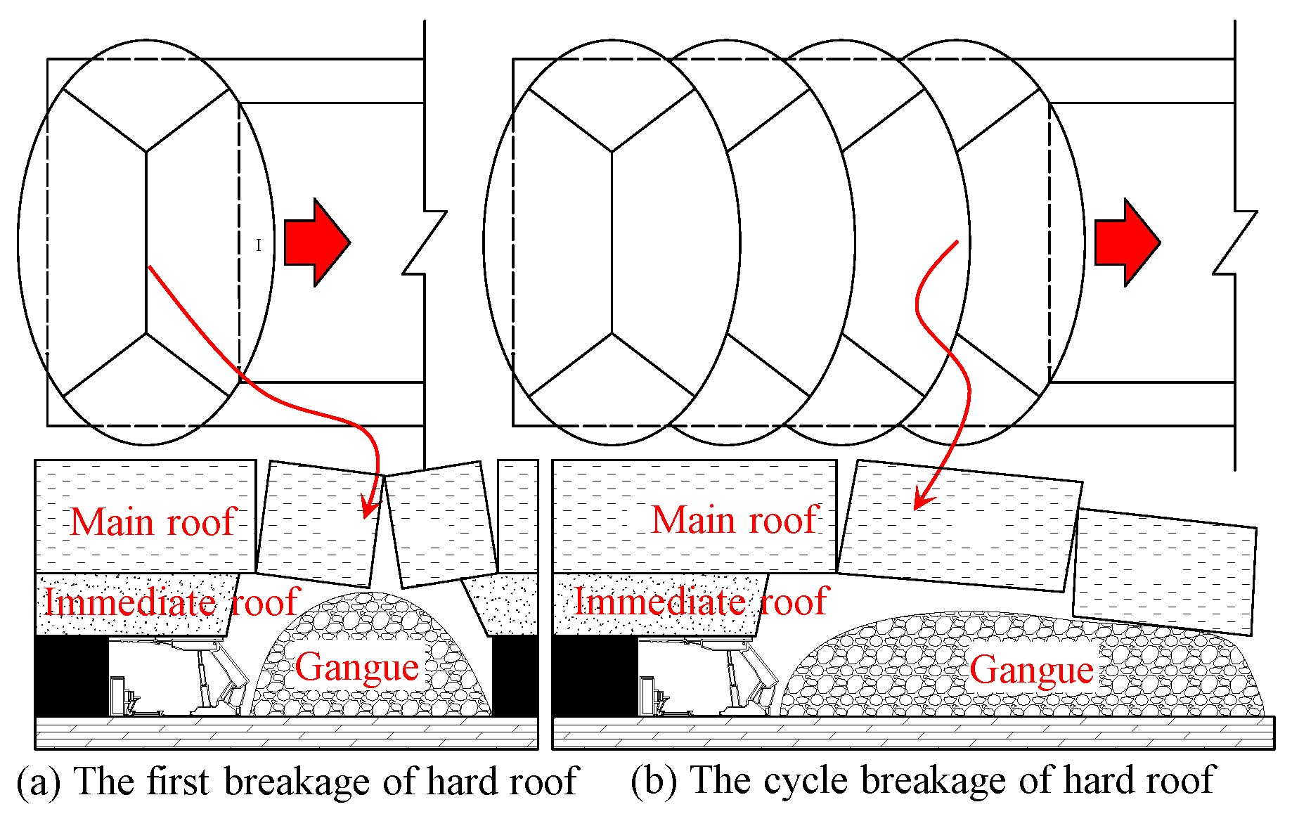
Figure 4.
Schematic diagram of disaster mechanisms induced by thick hard roof fracture.
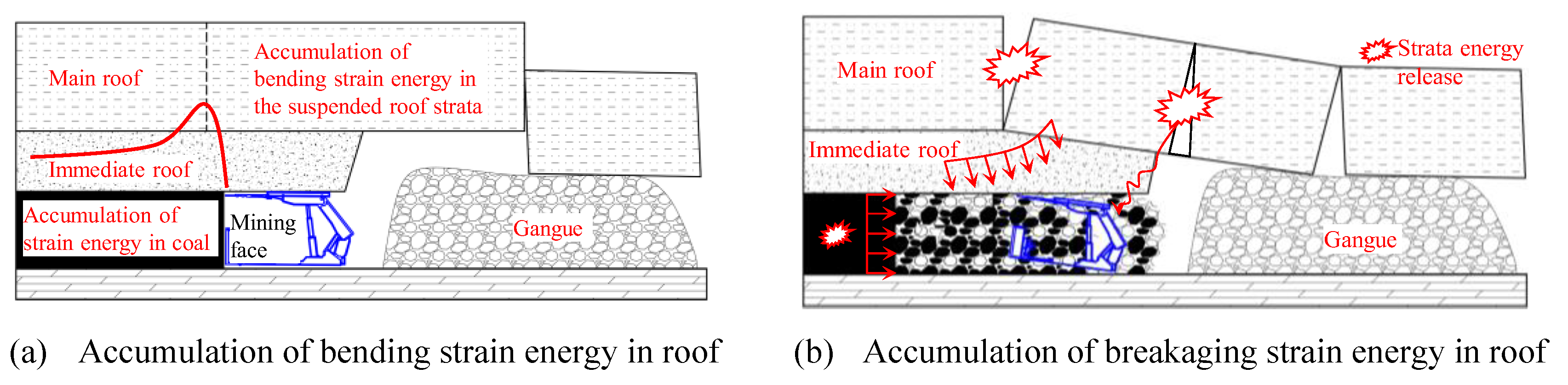
Figure 5.
Mechanical model for the fracture of thick-hard roof .
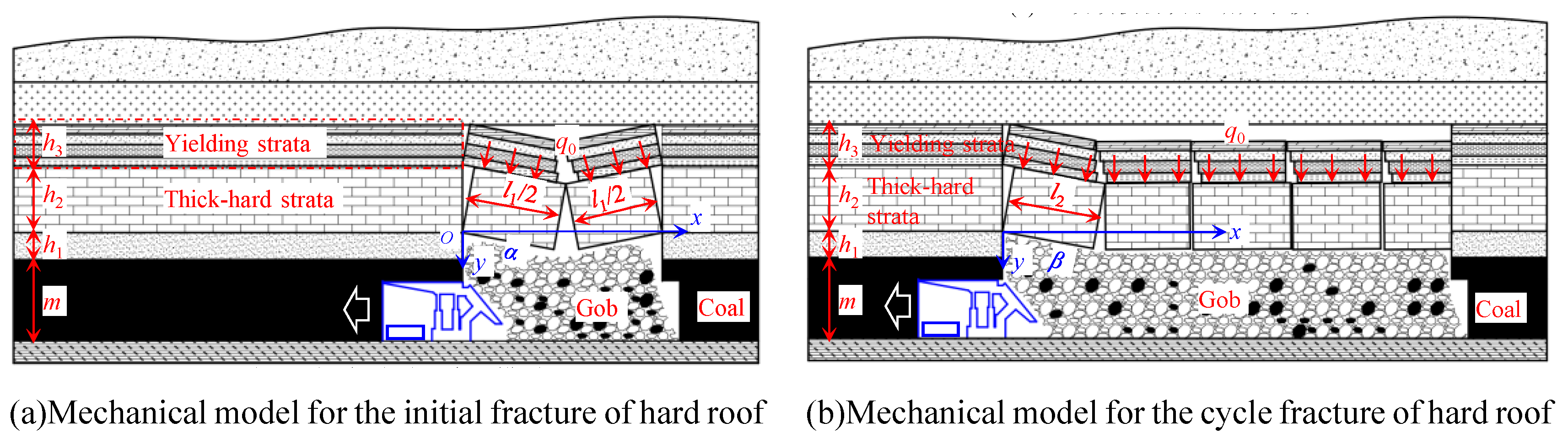
Figure 6.
Criterion for the generation of rock burst.
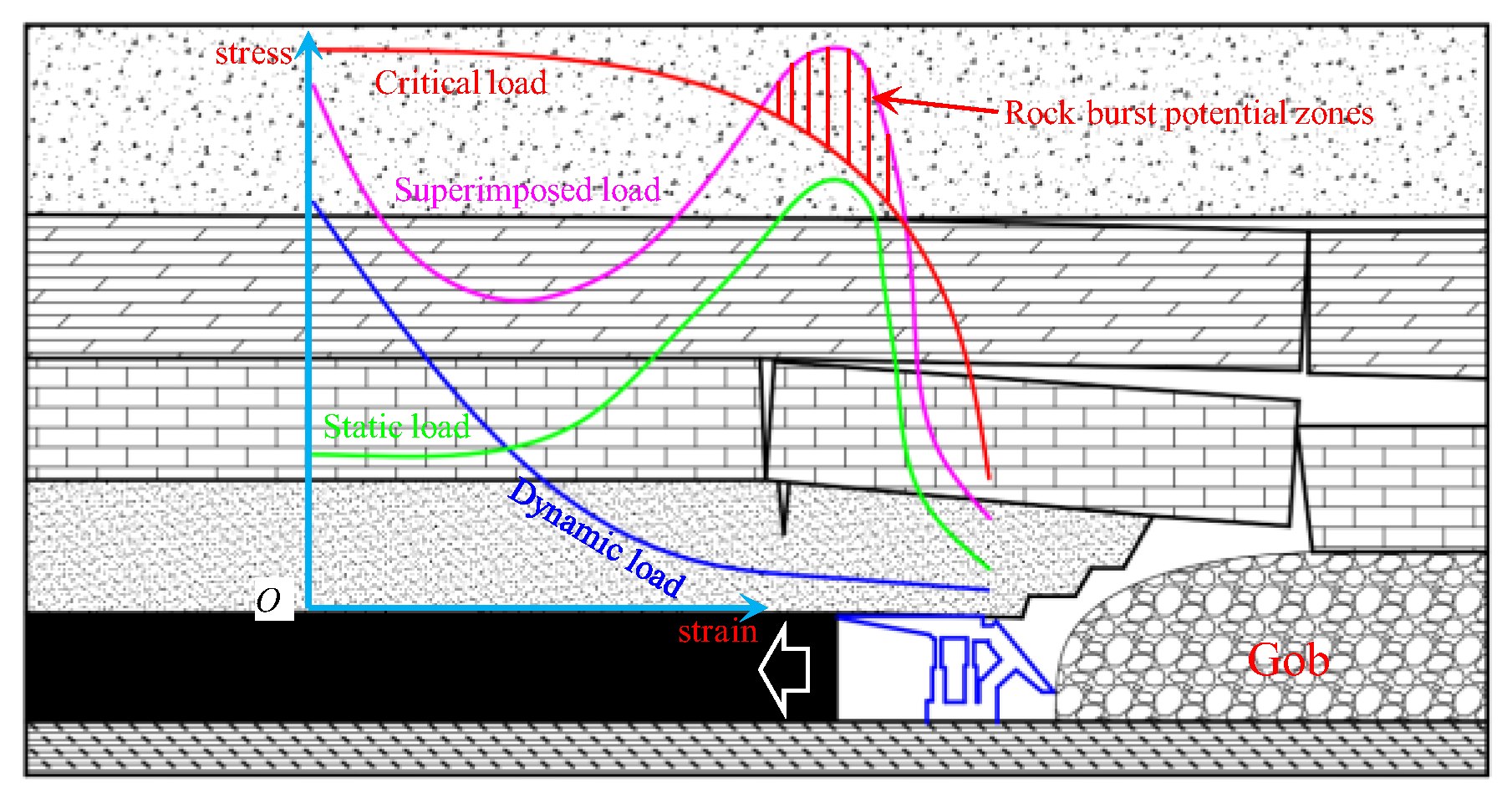
Figure 7.
Influencing factors of total energy released by initial fracture of the hard roof.
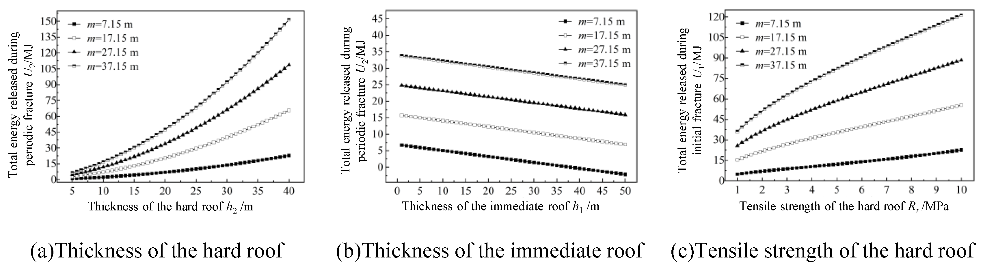
Figure 8.
Influencing factors of total energy released by periodic fracture of hard roof.
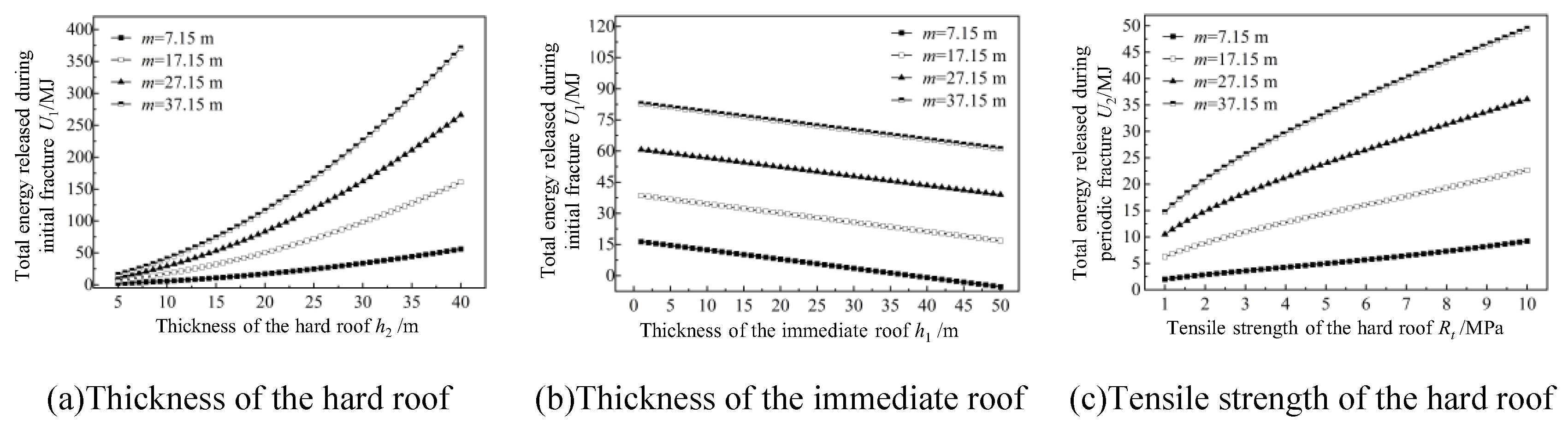
Figure 9.
Principle of directional long borehole hydraulic fracturing technology.

Figure 10.
Directional hydraulic fracturing scheme of 15311-south working face.
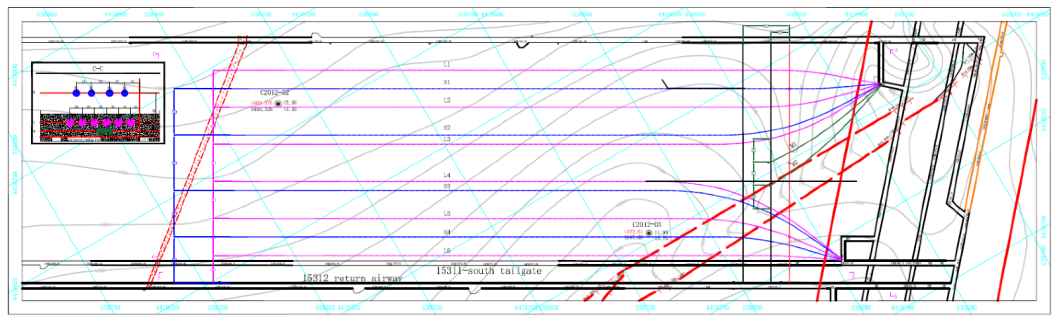
Figure 11.
Characteristics of thick-hard roof fracture before and after fracturing.
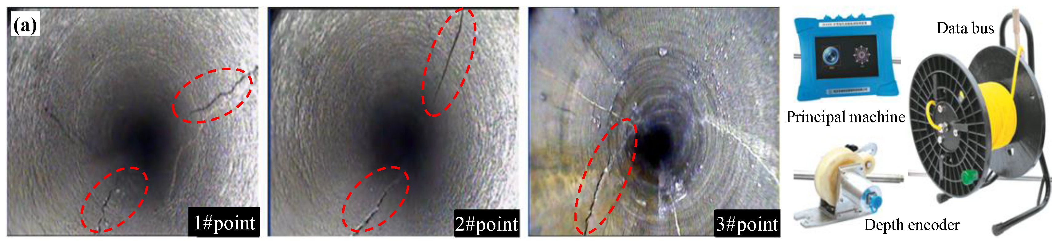
Figure 12.
Water injection pressure curve of directional hydraulic fracturing.
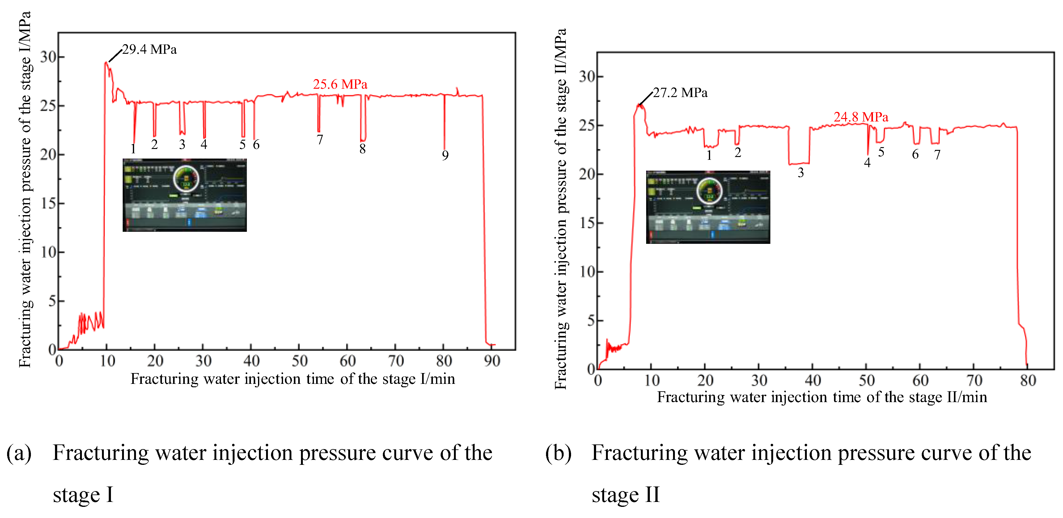
Figure 13.
Roadway deformation and coal stress monitoring curve
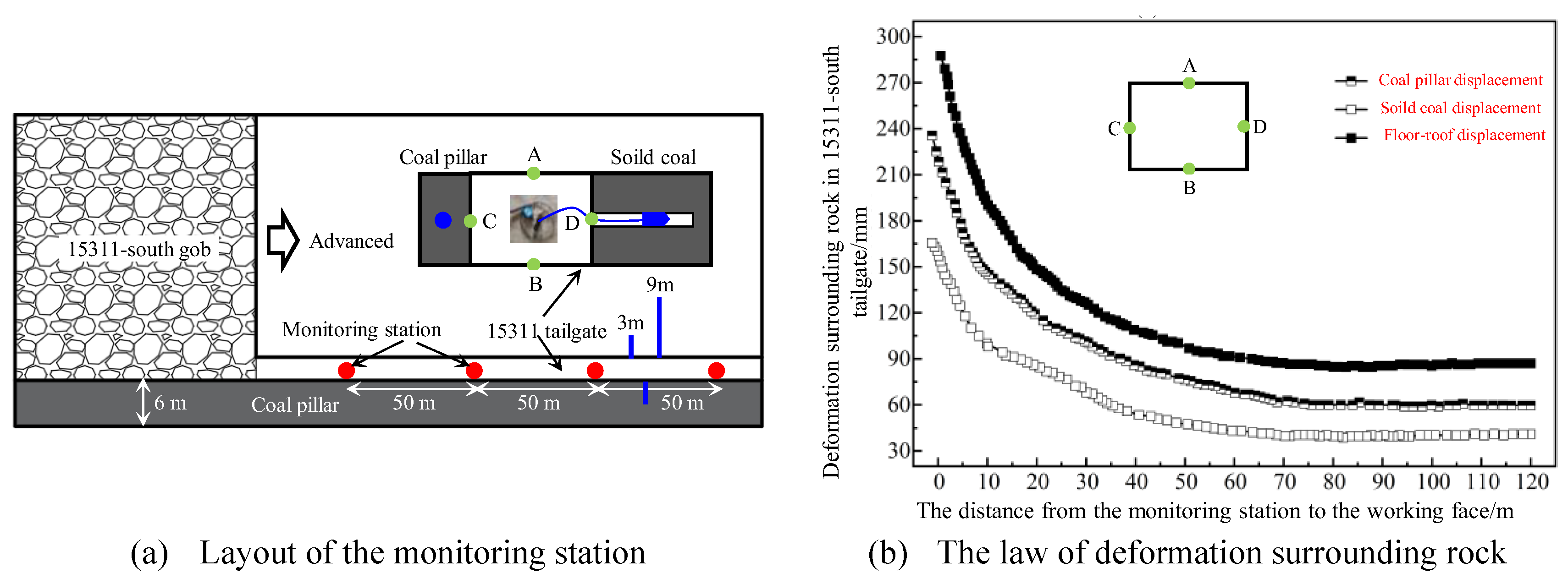
Figure 14.
The pressure distribution pattern in the mining area before and after hydraulic fracturing.
Figure 14.
The pressure distribution pattern in the mining area before and after hydraulic fracturing.
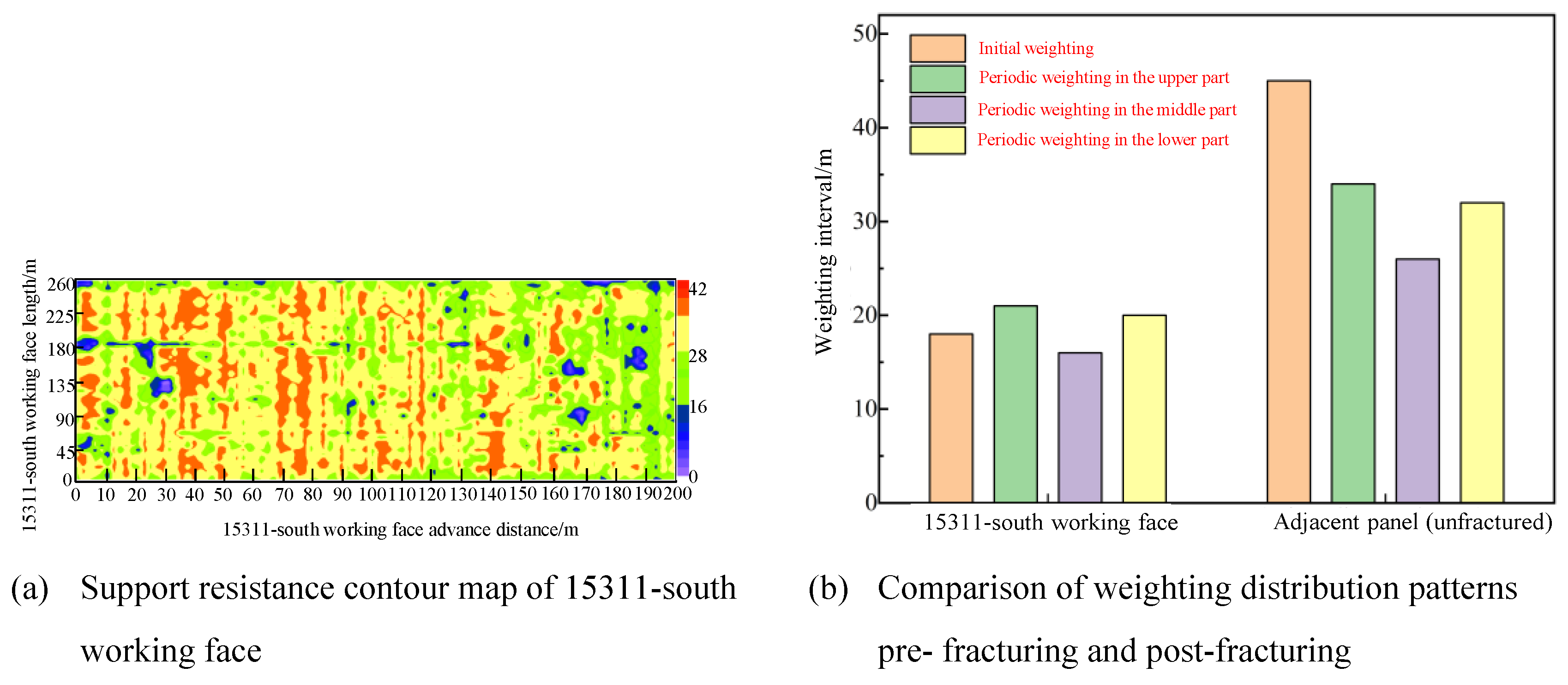

Table 1.
Physical and mechanical parameters and geometric characteristics of coal and rock mass.
| Influencing Factors | Variables | Value |
| The thickness of immediate roof | h1 | 12.28 m |
| The density of hard roof | ρ2 | 2500 kg/m3 |
| The elastic modulus of hard roof | E | 6.4 GPa |
| The thickness of hard roof | h2 | 15.46 m |
| The mining height of coal seam | m | 27.15 m |
| Overburden load on hard roof | q0 | 600 kPa |
| The tensile strength of hard roof | Rt | 4.54 MPa |
| The bulking factor of immediate roof | k | 1.2 |
| The density of overburden strata | ρ3i | 2400 kg/m3 |
| The thickness of overburden strata | h3i | 14.56 m |
Table 3.
Design parameters of directional hydraulic fracturing in 15311-south working face.
| Borehole number | Initial hole azimuth(°) | Initial hole dip angle(°) | Target azimuth(°) | Borehole diameter(mm) | Start point(m) | End point(m) | Fracturing stage(m) | Fracturing zone(m) |
| H1 Borehole | 295.5 | 10 | 300.15 | 120 | 0 | 705 | 150-705 | 48m |
| H2 Borehole | 272 | 10 | 0 | 717 | 162-717 | |||
| L1 Borehole | 310.5 | 7 | 0 | 699 | 150-699 | 15m | ||
| L2 Borehole | 284.5 | 7 | 0 | 705 | 150-705 | |||
| L3 Borehole | 268 | 7 | 0 | 717 | 162-717 | |||
| M1 Borehole | 260 | 10 | 0 | 150 | - | 6m | ||
| M2 Borehole | 252 | 10 | 0 | 165 | - | |||
| H3 Borehole | 335 | 10 | 0 | 681 | 126-681 | 48m | ||
| H4 Borehole | 316 | 10 | 0 | 669 | 114-669 | |||
| L4 Borehole | 338 | 7 | 0 | 681 | 126-681 | 15m | ||
| L5 Borehole | 324 | 7 | 0 | 669 | 114-669 | |||
| L6 Borehole | 304.5 | 7 | 0 | 663 | 108-663 |
Disclaimer/Publisher’s Note: The statements, opinions and data contained in all publications are solely those of the individual author(s) and contributor(s) and not of MDPI and/or the editor(s). MDPI and/or the editor(s) disclaim responsibility for any injury to people or property resulting from any ideas, methods, instructions or products referred to in the content. |
© 2025 by the authors. Licensee MDPI, Basel, Switzerland. This article is an open access article distributed under the terms and conditions of the Creative Commons Attribution (CC BY) license (http://creativecommons.org/licenses/by/4.0/).
Copyright: This open access article is published under a Creative Commons CC BY 4.0 license, which permit the free download, distribution, and reuse, provided that the author and preprint are cited in any reuse.


