Submitted:
13 January 2026
Posted:
14 January 2026
You are already at the latest version
Abstract
In this paper a folding wing based on gear meshing deformation mechanism is developed, focusing on structural analysis and further optimization of the folding wing. Compared with existing folding wing concepts, the deformation mode of this wing is easier to manufacture and implement in engineering. A dynamic contact finite element model of gear meshing is established in ABAQUS, achieving the transmission of motion. The meshing simulation on the gear pair and dynamic strength analysis on the gear mechanism is conducted to obtain stress analysis. The results shows that the mechanism meets the strength requirements. Further dynamic numerical simulations are conducted on the outboard wing to determine the hazardous area of the load, indicating that the folding wing meets the strength requirements. At the same time, the analysis is conducted on the displacement at the tip of the outboard wing, indicating that the folding motion is relatively gentle. Finally, based on the stress analysis results, a weight reduction topology design is carried out for the spoke area of the gear and the rib structure of the folding wing using the variable density method. While ensuring strength, the optimal distribution of materials is sought by using as little material as possible, and the model is reconstructed according to the optimization results. The optimization results show that the weight reduction effect is significant.
Keywords:
folding wing
; gear meshing
; deformation mechanism
; dynamic strength
; optimization
1. Introduction
The aircraft with morphing wing refers to aircraft that can change their aerodynamic shape during flight, such as aspect ratio, sweep angle, and wing area, to achieve optimal performance in different flight conditions [1,2].
At present, folding technology is divided into folding wings and folding winglets based on their application areas. According to the folding method, it can be divided into horizontal folding and vertical folding [3]. For example, Lockheed · Martin’s “folding wing” concept is highly favored, which involves changing the shape of the wings in a folding manner under different flight requirements. The wings are fully extended for takeoff or cruising, and fully retracted for high-speed or maneuvering flight [4]. The folding winglet proposed by the University of Bristol has achieved gust alleviation. By establishing an aeroelastic model of the folding wingtip, conducting parameter analysis, wind tunnel tests, and flight tests, the gust alleviation effect of the folding wingtip has been verified [5].
For folding wing structures, it is necessary to have the load-bearing capacity, deformation, and lightweight, while also being limited by the geometric dimensions of the wing and weight. So, this leads to efficient implementation of structural load-bearing and driving deformation [6]. Therefore, there are only a few practical designs available. For example, the X-47B unmanned aerial vehicle developed in the United States can fold up 130 degrees, and the deformation mechanism adopts a hinge multilink mechanism. The driving source is a hydraulic actuator, which can drive the folding mechanism to achieve retraction [4]. A folding mechanism for folding wings using planetary gears as the main transmission pair has been designed [7,8]. Zhang utilizes high-precision servo servos and high-strength worm gears as driving devices for the folding motion of the wing, achieving the folding motion of the wing [9]. However, these transmission mechanisms, such as planetary gear transmission, have the shortcomings of complex structure, difficult manufacturing and installation, and the hinge connection drive method is not easy to operate, making it difficult to meet design requirements. Han et al. [10] embeds shape memory alloy wires and glass fibers together into soft body materials to achieve folding deformation of wing tips. Li Wei et al. [11] uses shape memory alloy springs as drivers to achieve wing tip folding deformation. NASA’s spanwise morphing wing uses shape memory alloy torque tubes as drivers to achieve the folding of the outboard wing [12] Under existing conditions, there are still some limitations to applying shape memory alloys in practice, such as low driving efficiency.
The concept of a morphing aircraft with folding wing based on gear meshing deformation mechanism is proposed. And a mechanical model and virtual prototype suitable for the folding wing deformation mechanism is established. On this basis, the structural dynamic analysis of the folding wing is carried out. and the deformation mechanism and outboard wing of the folding wing are analyzed for force and motion through numerical simulation results to investigate the mechanical behavior during the morphing process. Based on the force analysis of the folding wing, the deformation mechanism of the folding wing and the rib structure of the outboard wing are optimized for weight reduction by the variable density method [13,14,15].
2. Design Concept of Folding Wing
This folding wing is divided into three sections: fuselage, inboard wing, and outboard wing, as shown in Figure 1. Each wing segment is tightly connected by hinge shafts, and the fuselage is fixed. The inboard and outboard wings can be continuously folded around the axis direction parallel to the fuselage within the range of 0° -120° through the shafts at each connection.
During the morphing process, the wingspan and reference area of the folding wing will decrease, while the wing will generate significant aerodynamic forces and moments, which have a significant impact on the aerodynamic characteristics. Folding wings can maximize aerodynamic advantages by changing the angle, resulting in better flight performance. When the folding angle is 0°, the fuselage, inboard wing, and outboard wing are in the same plane, with the largest wingspan and wetted area. When the folding angle is 120°, the wingspan and wetted area are minimized. The geometric parameters of each wing segment are shown in Table 1.
For folding wing, a driving mechanism is utilized to achieve the folding/folded motion. According to publicly available literature, the advantages and disadvantages of different drivers can be identified in Table 2. In this paper a gear meshing mechanism is used to achieve the folding and folded motion of the wing. The virtual prototype model of the folding wing and deformation mechanism - gear meshing mechanism are shown in Figure 2 and Figure 3.
Virtual prototype model diagram of gear meshing mechanism is shown in Figure 4. The gear meshing mechanism consists of two pairs of gears with different numbers of teeth and two driving motors. The motor shaft passes through the center of the small gear and is fixedly connected to the small gear. The motor is fixedly connected to the wing, and the large gear is fixed on a fixed shaft. The fixed shaft is fixedly connected to the wing, realizing the morphing motion of the movable wing relative to the fixed wing. Due to the fact that the components of the gear meshing mechanism consist only of two sets of four gears and driving motors, it is simple to construct, highly reliable, and easy to manufacture. However, there are also problems such as the motion mechanism being not compact, the contact force between teeth being large, high requirements for the driving motor, and the mechanism moving unevenly when the wing is folded.
3. Analysis and Optimization of Folding Wing
3.1. Structural Dynamics Analysis of Folding Wing
The folding wings of morphing aircraft have more motion mechanisms and components than conventional aircraft wings. And after the morphing the integrity of the wing structure may be damaged. When the shape of the wing changes, its internal structure must have sufficient load-bearing capacity. When the folding wing undergoes morphing motion, due to the large load transmitted between each section of the wing, especially at the gear meshing and the connection between the tabs and the shafts. The failure of gear transmission will directly affect the transmission performance of the deformation mechanism. At the same time, excessive stress at the tabs will also reduce the reliability of the structure. Therefore, accurate analysis of the stress at the gears and tabs is particularly important.
3.1.1. Dynamic Analysis of Deformation Mechanism
3.1.1.1. Finite Element Model of Deformation Mechanism
Motion coupling can restrict a large number of nodes (slave nodes) to rigid body motion of a single node (master node), allowing for arbitrary selection of restricted degrees of freedom for slave nodes, with each slave node having a separate motion relationship with the master node. Therefore, motion coupling can be described as rotational and translational coupling. This type of motion coupling enables elements without rotational degrees of freedom to achieve rotational motion.
The nonlinear finite element software ABAQUS provides contact algorithms with high computational accuracy. The contact problem in mechanics involves complex material, geometric, and boundary nonlinear problems. The nonlinearity of the contact interface includes the contact area, contact state, and contact conditions, which make the solution of the contact problem complex. The two basic solutions commonly used are the Lagrange multiplier method and the penalty function method. The penalty function method does not increase the degrees of freedom, keeping the coefficient matrix positive definite. ABAQUS uses penalty functions to solve contact problems [16]. The solution process is shown in Figure 5.
The gear meshing mechanism of the folding wing is taken as the object, made of 45 steels, and its basic parameters are shown in Table 3 and Table 4.
Due to the weak modeling ability of ABAQUS for complex surfaces, a pair of gear pairs with accurate meshing are established in CATIA, and then imported into ABAQUS through IGS format files. The assembled model in ABAQUS is shown in Figure 6.
Considering the complex structure of gears, geometric mesh division should be carried out first. The mesh division should be as regular as possible in the expected heavily stressed areas. At the same time, the mesh at the tooth profile boundary should reach a certain density to ensure the smoothness of the tooth surface when continuing to generate the body mesh. Element refinement should be carried out at the chamfer. ABAQUS can use SWEEP technology to mesh complex areas. After generating a two-dimensional mesh on the end face, the mesh is divided using SWEEP method.
There are two methods for contact simulation in ABAQUS/Standard: one is surface-based method and the other one is contact element-based method. Therefore, it is necessary to create surfaces that may come into contact separately on each component of the model. Then, it is necessary to determine which pair of surfaces may come into contact with each other. Finally, a constitutive model must be defined to control the interaction between the contact surfaces [17]. When defining contact pairs, it is necessary to correctly select the primary and secondary surfaces to ensure minimal penetration during the simulation process. When the node density is relatively close, the surface with higher material stiffness is chosen as the main surface and the softer surface as the secondary surface. Since the materials of the two gears in this paper are the same, the master and slave surfaces can be arbitrarily selected.
The contact problem requires defining a constitutive model that controls the interaction between the contact surfaces. The distance between two surfaces is a gap. When the gap between two surfaces becomes zero, contact constraints are applied in ABAQUS. When the contact pressure between the contact surfaces becomes zero or negative, the two contact surfaces separate and the constraint is removed, which represents a “hard” contact. The tangential behavior of contact described in ABAQUS is divided into finite slip and small slip. When using finite slip, it is necessary to determine the main surface area in contact with each node of the secondary surface. When using small sliding, the relationship between the face node and the main face node is established at the beginning of the simulation. When a surface comes into contact, tangential and normal forces are generally transmitted between the contact surfaces. In the analysis, it is necessary to consider the frictional force that prevents relative sliding between surfaces.
Contact pairs on the tooth surfaces of two gears is established, using finite slip to allow for movement of the contact surface. In the case of relative motion between the driving wheel and the driven wheel teeth, the influence of friction on the tooth surface contact force should be considered as much as possible. According to the gear manual, the sliding coefficient of the gear pair is 0.05-0.1 with lubrication and 0.1-0.2 without lubrication. The Coulomb friction coefficient used in this paper is equivalent to the friction coefficient under harsh working conditions.
During the meshing transmission process of gears, the driving wheel rotates at a certain speed, driving the driven wheel to move. The driven wheel generates a counter torque to the driving gear, which is transmitted between the two gears through tooth contact [18,19]. A reference point control method is employed to simulate the rotational speed and transmission of the gear pair for the application of rotational speed. For the driving gear, the speed reference point is defined and the rotational speed is applied around the axis. The application of torque, the load reference point is defined, on which the rotational degrees of freedom in two directions of the reference point are limited. The rotational degrees of freedom of the driven gear around the axis is free, while the translational degrees of freedom in three directions are constrained. Based on the torque results at the axis, an amplitude curve is used in ABAQUS to define any load that varies over time. The final finite element model is shown in Figure 7.
3.1.1.2. Analysis of Numerical Simulation Results of Deformation Mechanism
Through simulation analysis of gear drive, not only can the correctness of the model be verified, but also the change rule of contact stress and tooth root bending stress in various meshing states of the tooth surface can be obtained. Figure 8 shows the curve of the angular velocity of the driven gear. The angular velocity of the driving gear is 1.396 rad/s, and the angular velocity curve of the driven gear is basically a straight line, fluctuating around 0.698 rad/s. Therefore, the ratio of the angular velocities of the driving and driven gears is equal to the transmission ratio, satisfying the relationship of the gear pair transmission ratio. Meanwhile, Figure 9 shows the curve of the contact area. It can be seen that during the gear meshing transmission process, the contact area between the two surfaces is constantly changing, indicating the complexity of the contact relationship in gear transmission and verifying the correctness of the established model, which is consistent with the actual situation.
Figure 10 shows the curve of contact forces in different directions caused by friction. It can be seen that the influence of friction on the tooth surface contact force cannot be ignored. Therefore, it should be fully considered in the analysis of gear meshing motion. Due to a significant impact at the beginning of meshing and the appearance of the maximum torque in the torque application , the curve of the contact force caused by friction shows the maximum value. Secondly, friction causes circumferential contact forces to be greater than radial contact forces.
The stress cloud of the gear contact area at different meshing positions during the meshing motion of two gears is shown in Figure 11, reflecting the meshing performance of the gear pair.
From Figure 11, it can be seen that the actual dynamic stress distribution obtained is consistent with the mechanical analysis. The areas with relatively high stress are mainly concentrated near the contact and tooth roots, and the stress influence zone is only near the contact tooth pair. For areas far from the contact, the stress is relatively low, which conforms to Saint Vedant’s law in elastic mechanics.
During the meshing process of gears, the root of the driving gear teeth collides with the top of the driven gear teeth, generating significant contact stress and resulting in meshing impact [20]. When exiting, the top of the driving gear teeth collides with the root of the driven gear teeth, generating significant contact stress and creating a meshing impact. Due to the presence of gear tooth errors and deformation during the meshing process, the meshing and disengagement nodes of the gear teeth will deviate from the theoretical nodes, resulting in collisions between the driving gear and the driven gear, thereby generating significant stress. The stress can suddenly increase to 294MPa in a short time.
Due to the fact that the edges of the two gears teeth are not parallel and aligned, but staggered and tangent, severe shear phenomena occur under load, resulting in stress concentration at both ends of the gear teeth. At this point, the contact area is no longer rectangular, but slightly increases at both ends, with high stress at the ends. There is severe stress concentration at both ends of the contact area, and the load distribution along the tooth direction is also uneven. In addition, due to the initial meshing and the obstruction of the driven gear, the driving gear cannot rotate smoothly, which can cause complex vibration responses. This is also the main reason for the uneven stress distribution of the meshing teeth along the tooth width direction. These can all be reflected in Figure 12 and Figure 13. In order to ensure uniform distribution of load and reduce stress concentration, deformation treatment is carried out.
3.1.2. Dynamic Analysis of Wing Structure
The process of converting from an actual model to a finite element model requires a reasonable simplification of the original model, removing several minor details that have little impact on the investigation purpose. Otherwise, the calculation process will be very extensive and even impossible to implement. Therefore, the wing structure of the morphing aircraft is simplified in this paper to determine the modeling scheme, and finally the outboard wing is selected as the analysis object for dynamic modeling.
3.1.2.1. Finite Element Model of Wing Structure
For the outboard wing structure of the folding wing, continuous shell elements are used for the skin and ribs, and solid elements are used for the wing beams. The material of the skin is LY-12, and the material of the ribs is 30CrMn. The material parameters and material of different component are shown in Table 5 and Table 6.
Due to the complexity of the folding wing structure model, if the wing beams, skin, ribs, and tabs are imported into ABAQUS separately, their connection parts are needed to be set up for contact, which will increase the complexity of establishing the finite element model. Due to the loss of geometric features when importing CAD models into CAE software, different geometric structures generate different types of meshes, requiring processing of the geometric models. HYPERMESH is used to improve the quality of finite element models by processing geometric surfaces, geometric bodies, and small features in this paper.
The wing rib model generated in CATIA is a three-dimensional geometric body, and the mesh generation is complicated due to the holes in the wing ribs. Therefore, the method of extracting the mid surface of the wing rib is adopted, which is beneficial for the generation of SHELL elements. Using a two-dimensional AUTOMESH panel, adjust the size, density, and type to perform element partitioning. To ensure the quality around the circular hole, an additional layer of WASHER is added around the hole.
When meshing beams, the surface of the beam is first divided into mappable shapes, and then the SOLID MAP function is used to define two opposing faces (source face and target face) and directly connect the source face and target face to generate SOLID elements. The division elements of the beam should be coordinated with the wing surface as much as possible, because the beam nodes need to be connected to the wing surface nodes as a common node.
The mesh division method of the tab is similar to the division of the beam, which will not be repeated here, but the nodes at the connection with the beam is needed to be consistent with the nodes of the beam.
Firstly, the skin is partitioned based on the positions of the beams and wing ribs. A two-dimensional AUTOMESH panel is used to adjust the size, density, and type of elements, as well as the number of nodes, in order to partition the mesh and make most of the QUAD element. In addition, due to the partition of the skin and the use of SHELL elements, it is necessary to maintain consistency in the normal direction of the elements. Adjust the normal direction of the element through the NORMAL panel.
Finally, the elements of each component using IGES panels are assembled, which set appropriate tolerance sizes to merge nodes at different component connections to improve the connectivity of the entire model. The finite element model of the outboard wing of the folding wing is shown in Figure 14.
In order to obtain the correct solution, it is necessary to define constraints reasonably. By defining a reference point at the center of the tab hole and coupling it with the surface of the tab hole, the rotational degrees of freedom of the reference point around the Z-axis are released, while the remaining degrees of freedom of the reference point are fixed. The local coupling points and applied loads are shown in Figure 15 and Figure 16.
3.1.2.2. Analysis of Simulation Results of the Outboard Wing of a Folding Wing
After solving the loading of the outboard wing of the folding wing, it can be seen from the dynamic stress cloud that the overall stress is relatively small, but during the loading process, the stress at the tab is relatively high. Due to the torque applied at the center of the tab, the entire outboard wing needs to be driven, and the amplitude of the loading varies greatly, with fluctuating stress distribution over time. The local stress is shown in Figure 17.
From the stress cloud at different time on the tab, it can be seen that the stress amplitude on the tab is changing and there is a phenomenon of stress concentration, with the maximum values mainly concentrated at the center hole of the tab and the connection with the beam. During the entire loading process, the maximum stress on the tab occurred at 1.5 seconds.
The displacement curve at the wingtip is shown in Figure 18. It can be seen that during the loading process, the displacement is a slowly increasing process, which conforms to the definitions of boundary and load conditions. At the same time, the displacement changes slowly, which is conducive to motion control.
Through the dynamic analysis of the outboard wing structure of the folding wing, it can be seen that although the overall stress level of the outboard wing structure is relatively low, far less than the material’s failure strength, high stress occurs at the center hole of the tab and the connection between the tab and the beam. Secondly, due to the difference in size between the front and rear tabs, the stress range on the rear tab is larger. Therefore, corresponding measures should be taken to improve.
3.2. Optimization Design of Folding Wing
Folding wings increases the complexity and weight of the structure. However, considering some design industries such as aerospace that prioritize quality as an important indicator, how to reduce quality, lower costs, and improve lifespan while meeting usage requirements has become one of the important issues that needs to be addressed. In aircraft structures, the main function of wing ribs is to maintain the shape of the wing, and their contribution to the total bending stiffness of the wing is relatively small. However, the weight of wing ribs accounts for a considerable proportion of the structural importance of the wing box. Therefore, it is necessary to reduce the structural weight of wing ribs through structural optimization methods.
3.2.1. Theory and Process of Structural Optimization
Topology optimization is a mathematical method that can generate optimized shapes and material distributions within a given spatial structure. According to certain design criteria, under the constraint conditions of stress, stiffness, displacement, frequency, etc., holes are drilled, unnecessary components and materials are removed in the structure (i.e. changes in the layout of structural components and node connections), so that the structure achieves optimal performance in the specified sense. Structural topology optimization generally uses the “base structure” as the initial structure for optimization, and finite element mesh division is performed on the selected base structure. Therefore, the design variables of topology optimization become variables that describe whether the elements exist, and the structural topology optimization problem becomes a discrete variable optimization problem.
By discretizing the region into finite element grids, OPTISTRUCT calculates material properties for each element. Under given constraints, the material distribution is modified using the approximation and optimization algorithms in OPTISTRUCT to optimize the design objective given by the user. When the objective function changes below the given tolerance in any three consecutive iterations, the convergence result is obtained.
The response (or any combination) defined by the objective or constraint function used for topology optimization is shown in Table 7.
When the element is in the topology design area, its stress, strain, or force cannot be constrained. When the element is not in the topology design area, the responses listed in Table 8 can be used as objective or constraint functions.
The variable density method is also a common topology optimization method, which belongs to the material (physical) description method. For the density method, the material density of each unit is directly used as a design variable and continuously varies between 0-1. 0 and 1 respectively represent empty or real. The median value is the same as the homogenization method, representing the hypothetical material density value. Based on this method, the elastic modulus of the material is assumed to be linearly related to density. This method is based on isotropic materials and does not require the introduction of microstructures or additional homogenization processes. The program implementation is simple and the computational efficiency is high.
In OptiStruct, the uniform method is only used for homogeneous isotropic materials, and the effective material properties calculated by the half density element are anisotropic. The density method can be used for both isotropic and anisotropic materials (including composite materials). The effective material properties used for calculation are proportional to the properties of the original material. Due to its effectiveness and universal applicability, the density method is the default method for all topology optimization problems, which uses the variable density method based on the OptiStruct solver.
A typical optimization mathematical model can be described as follows:
There are n design variables . Under the constraints of and , the minimum objective functionis abbreviated as:
The topology optimization process is shown in Figure 19. For structures that are directly redesigned, they should be designed according to the three elements of topology; For optimization based on the original structure, it is necessary to first analyze the original model, determine the operating conditions, and provide reference parameters for the next step of topology optimization. The three elements of optimization include: design variables, objective functions, and constraints.
3.2.2. Optimization Design of Deformation Mechanism
The structure of a gear consists of three parts: the rim, the hub, and the spokes. The spokes are located between the wheel rim and the wheel hub. For the wheel rim, its design has been standardized. The wheel hub and shaft are designed to match, leaving little design space. Therefore, taking the large gear in the meshing mechanism as a model, weight reduction design is carried out for the spoke area of the gear, aiming to minimize the weight of the gear while ensuring strength. The OptiStruct module can achieve topology optimization of structures, seeking the optimal material distribution within a given design space. Define the flow pattern of materials through two methods: homogenization and density. Approximation methods and optimization algorithms are adopted to obtain the optimal loading path design scheme. In addition, the processability of the optimization model can also be considered to make the optimization results easier to design and manufacture.
3.2.2.1. Optimization of Deformation Mechanism
When performing mesh partitioning, the model is first segmented to obtain high-quality elements, and the design and non-design areas of the model are determined. The main mesh used for mesh partitioning in HyperMesh is hexahedral mesh. The torque condition of the deformation mechanism is analyzed, and the contact area between gear teeth is constrained. RBE2 is used to connect to the center point to simulate the rigid connection between the shaft hole and the shaft. A torque load of 6644N·mm is applied at this point, and the entire displacement of the gear are constrained to simulate the gear meshing condition, as shown in Figure 20.
Define design variables: Considering the working condition of the deformation mechanism, the rotational operating condition is selected as the topology optimized operating condition, and the spoke area is set as the designable area.
Define response: the volume fraction and strain energy of the design variable region is defined as the response. Constraints and objective function are defined. Stress is less than 294MPa (maximum stress), and upper limit of volume fraction is 0.3. By minimizing strain energy and implementing corresponding optimization control, discrete solutions can be obtained by eliminating intermediate density elements and density interleaved structures, resulting in more refined structures.
The symmetrical constraints to the design area applied to form a symmetrical design, eliminating the rotational inertia caused by asymmetric structures. The Optimization control is shown in Figure 21.
3.2.2.2. Optimization Results of Deformation Mechanism
Using the OptiStruct module, numerical simulations are conducted on the topology optimization finite element analysis model. After multiple iterations, the optimal model is obtained. Figure 22 shows the material distribution at a density threshold of 0.3. After optimization analysis and design, the weight of the structure has been reduced and the stiffness of the structure has been increased. Compared with some existing standard gears, the optimized spoke area has a certain degree of similarity, but the model in this paper has a better weight reduction effect while ensuring force transmission and motion.
3.2.3. Optimization Design of Wing Rib Structure
For the outboard wing of the folding wing, first finite element mesh division on the wing ribs of the folding wing is performed to determine the design area and non-design area. By using common nodes, the fixed connection between the wing ribs and wing beams can be achieved. The final element model is shown in Figure 23. The blue part is the wing beam, and the middle part is the design area. In order to analyze the load-bearing capacity of the outboard wing ribs, when the folding angle is 0 degrees, the lift received by the wing is distributed on the surface of the beam in the form of nodal forces, and all nodes on the surface of the center hole of the tab are reinforced and restrained to simulate a rigid connection with the shaft (not shown), as shown in Figure 24.
Based on the finite element analysis model, the calculation conditions are set and the OptiStruct module is used for static analysis. The analysis results are shown in Figure 25. The left side is the deformation cloud, and the right side is the stress cloud. It can be seen that the maximum deformation is 3.298mm and the maximum stress is 47.71MPa.
3.2.3.1. Optimization of Wing Rib Structure
Define design variables: the wing ribs connected to the beam is designated as the designable area, which is the middle area in the figure above.
Define response: the volume fraction and strain energy of the design variable region are defined as the response.
Define constraints and objective function: the upper limit of volume fraction is 0.5. The strain energy is minimum. And corresponding optimization control is carried out. The design area is applied to pattern repetition to achieve similar topology layout, that is, by specifying the structural style of one or more areas to be consistent with another area, or scaling proportionally along a certain direction, thereby the workload of process design and manufacturing processing are reduced. The mode repetition setting is shown in Figure 26.
3.2.3.2. Optimization Results of Wing Rib Structure
Using the OptiStruct module, numerical simulations are conducted on the topology optimization finite element analysis model. After multiple iterations, the optimal model is obtained and the calculation results are viewed in HYPERVIEW. Figure 27 shows the density distribution cloud of the topology optimization results. The red area (density=1) indicates that the material must be retained, while the blue area (density=0) indicates that the material can be removed. Figure 28 shows the material distribution at different density thresholds.
4. Conclusions
In this paper a folding wing is designed based on gear meshing deformation mechanism. Then, finite element method is used to establish the dynamic models of gear meshing deformation mechanism and folding wing structure, and dynamic analysis is carried out on them. Furthermore, based on the results of dynamic analysis, the gear meshing deformation mechanism and wing ribs are optimized and designed using the variable density method. The following conclusions can be drawn:
(1) Compared with existing folding wing concepts, the deformation mode of this wing is easy to process, manufacture, and implement in engineering.
(2) The overall stress level of the entire structure during the morphing process is relatively low, and severe stress concentration occurs at the gear meshing. The stress distribution along the tooth width direction is uneven, which can be improved by increasing the gear radius, increasing the tooth thickness, and modifying the tooth profile.
(3) The stress is higher at the center hole of the earpiece and at the connection between the tab and the beam. During the process of load transmission, the stress distribution range on the later earpiece is larger. Therefore, corresponding measures should be taken to improve the reliability of the structure.
(4) Based on the stress analysis results, the weight reduction optimization design of the gear meshing deformation mechanism and wing ribs is completed in OptiStruct, resulting in a structure that effectively transmits motion and force, ensuring the optimization of structural form and the minimization of structural weight. OptiStruct can make the optimization results easier to manufacture and improve their adaptability through specific constraints.
Author Contributions
Conceptualization, Y.N., and W.Z.; methodology, Y.N., and W.Z.; formal analysis, Y.N.; investigation, Y.N., and W.Z.; data curation, Y.N.; writing—original draft preparation, Y.N.; writing—review and editing, W.Z.. All authors have read and agreed to the published version of the manuscript.
Data Availability Statement
The data supporting the study findings can be provided upon request to the corresponding author. The data are not publicly available due to privacy.
Conflicts of Interest
The authors declare no conflicts of interest.
References
- Akhilesh, K. J.; Jayanth, N. K. Morphing Aircraft Concepts, Classifications, and Challenges. Smart Structures and Materials 2004: Industrial and Commercial Applications of Smart Structures Technologies. Bellingham: SPIE, Bellingham, WA, 2004: 213-224.
- European Commission. Flight path 2050: Europe's vision for aviation maintaining global leadership and serving society's needs. Luxemburg: European Commission-Directorate General for Mobility and Transport. 2011:1-11.
- Ni, Y.G.; Zhang, W., Lyu, Y., Zhao, H. Application and modeling analysis of wing folding technology. Flight Dynamics. 2020,38(6):1-7.
- Love, M. H.; Zink, P.S.; Stroud, R. L.; Bye, D. R.; Chase, C. Impact of Actuation Concepts on Morphing Aircraft Structures. AIAA 2004-1724.2004.
- Richard, T. M. WASP-a high survivable UAV. AIAA-2002-3439, Portsmouth, 2002.
- Zhang, J. Y.; Huang, K.; Wu G. Z.; et al. Key technologies and research progress of morphing aircraft structure.Electronics Optics & Control.2024, 31(1) : 1-13..
- Yan Z.K.; Wan, X.P.; Zhao M.Y. Dynamics analysis on planetary gear mechanism of a kind of folding-wing aircraft. Journal of Machine Design. 2009,26(12):49-51.
- Mi X.L.; Zhao, M.Y.; Meng, M.M.; Wan, X.P. Based on the floating-point Coded Genetic Algorithm Planetary Gear Train Folding Mechanism Optimization Design. Advances in Aeronautical Science and Engineering. 2013,4(3): 280-305.
- Zhang, Y.L.; The Rigid-flexible Aerodynamic Couple Dynamics of Folding Wing. Tianjin: Tianjin University of Technology.2021.
- Han, M. W.; Rodrigue, H.; Kin, H. I.; et al. Shape memory alloy /glass fiber woven composite for soft morphing winglets of unmanned aerial vehicles.Composite Structures. 2016, 140: 202-212..
- Li, W.; Xiong K.; Chen H.; Zhang X., et al. Research on Variable Cant Angle Winglets with Shape Memory Alloy Spring Actuators. Acta Aeronautica et Astronautica Sinica. 2012,33 (1) : 22-33..
- Moholt, M.; Benafano, O. Spanwise adaptive wing.Cleveland, OH: NASA’s Glenn Research Center, 2017.
- Liu, Y.; Chen, B.; Luo, F. OptiStruct Structural Analysis and Engineering Applications. China Machine Press: Beijing, China,2021;pp:187-190.
- Wang, X.; Zhang, D.; Zhao, C.; et al. Optimal design of lightweight serial robots by integrating topology optimization and parametric system optimization. Mechanism and Machine Theory. 2019,132:48-65.
- Zhang, S.L, et al. Structural Optimization Design Technology Based on Hyperworks. Mechanical Industry Press: Beijing, China, 2022; pp. 210-214.
- Zhuang, Z.; You, X.C.; Liao, J.H.; Cen, S., et al. Finite Element Analysis and Application Based on ABAQUS. Tsinghua University Press: Beijing, China, 2010; pp.312-320.
- Liang, D., Cao Y.P.; Xu, X.Y.; Jia, H.J; He, Z.Y. Tooth Surface Design and Dynamic Characteristics Analysis of Helical Non-circular Gear with Point Contact. Science Technology and Engineering. 2025,25 (4). 1458-1466.
- Jiang, J.K. Research on Design and NC Machining Technology for High-speed Involute Cylindrical Gears. Master's dissertation. Northwestern Polytechnical University, Xi‘an, 2015.
- Shu, T.L. Study on Machining Technology and Meshing Performance of Arthogonal Face-gear. Master's dissertation, Hunan University of Technology, Hunan, 2013.
- Ling, S.Y.; Zhang H.; Yang Z.X.; Zhang J.Y.; et al. Research on the Relevant Meshing Theories and Meshing Performance of Elliptical Toroidal Worm Gears and Cylindrical Gears. Journal of Mechanical Engineering. 2025,61(3): 325-336.
Figure 1.
Schematic diagram of folding wing: (a) Top view ; (b) Isometric View.
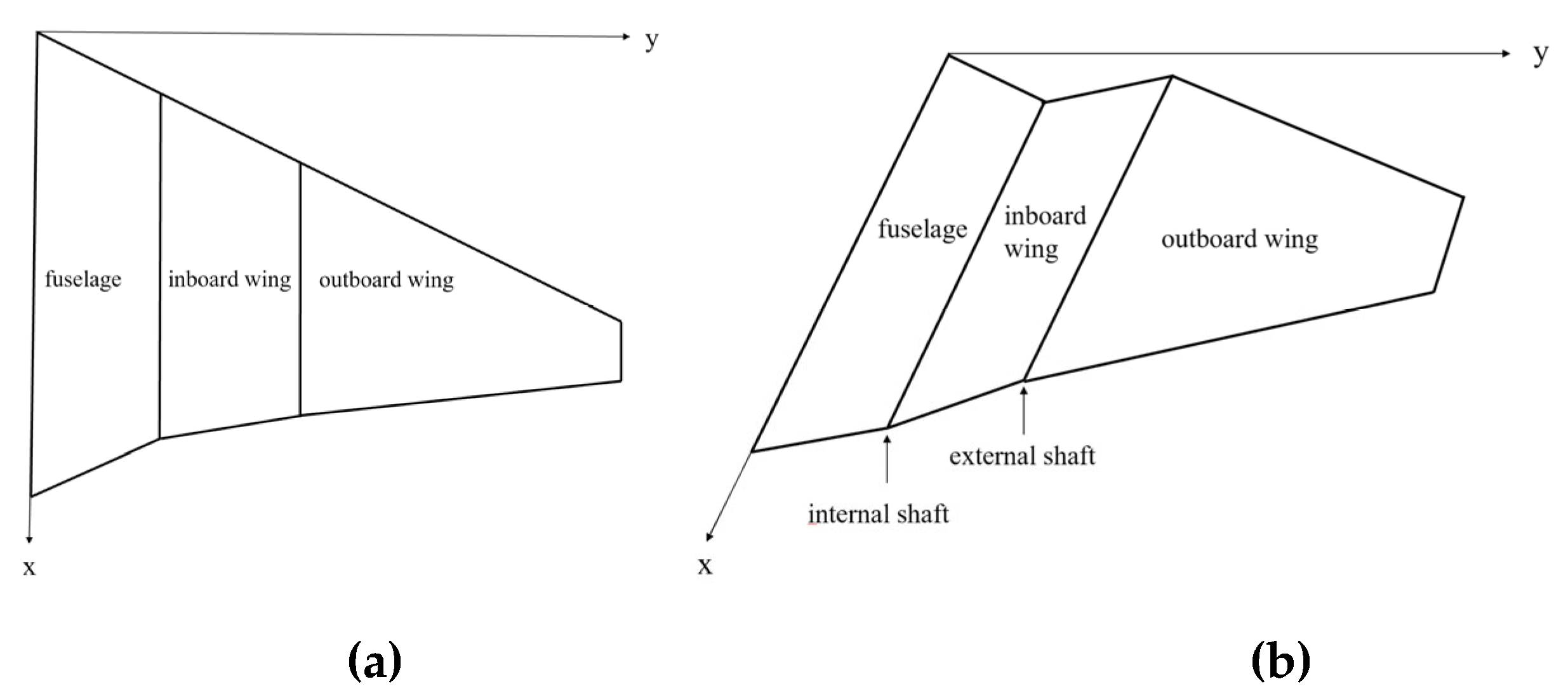
Figure 2.
Virtual prototype diagram of folding wing.
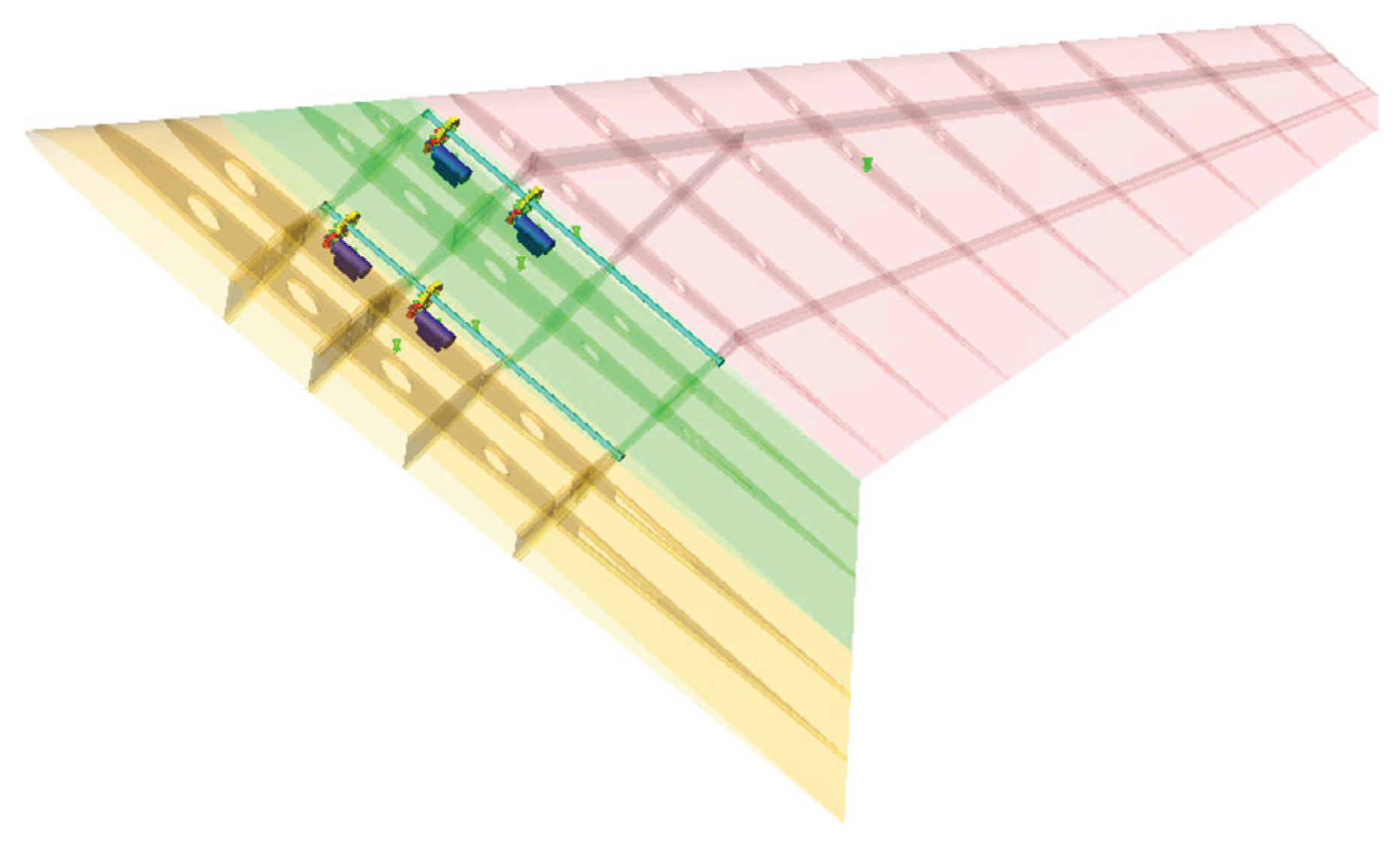
Figure 3.
Morphing motion diagram of folding wing: (a) 60° folding angle; (b) 120°folding angle.
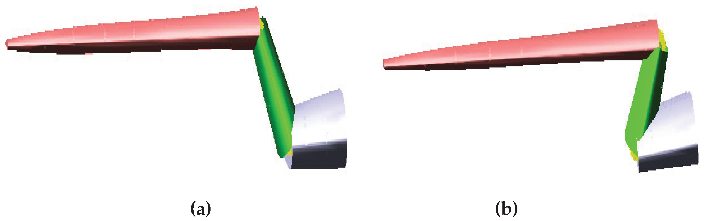
Figure 4.
Virtual prototype model diagram of gear meshing mechanism.
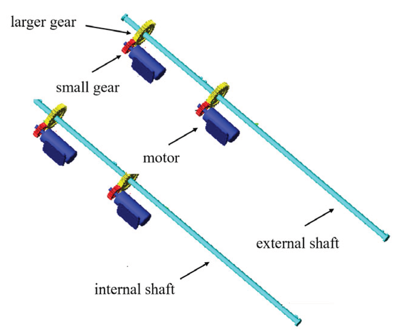
Figure 5.
Finite element solution process.
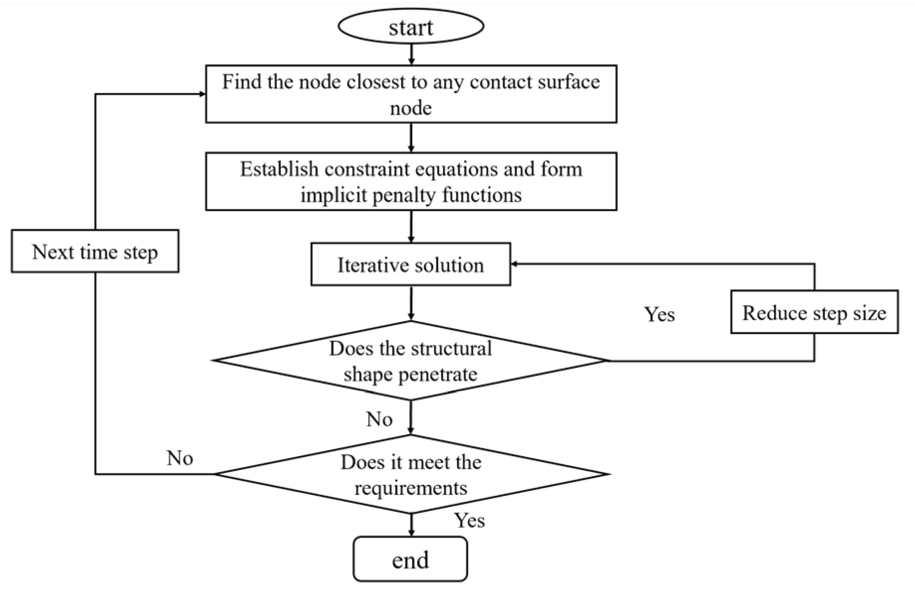
Figure 6.
Gear meshing assembly diagram.
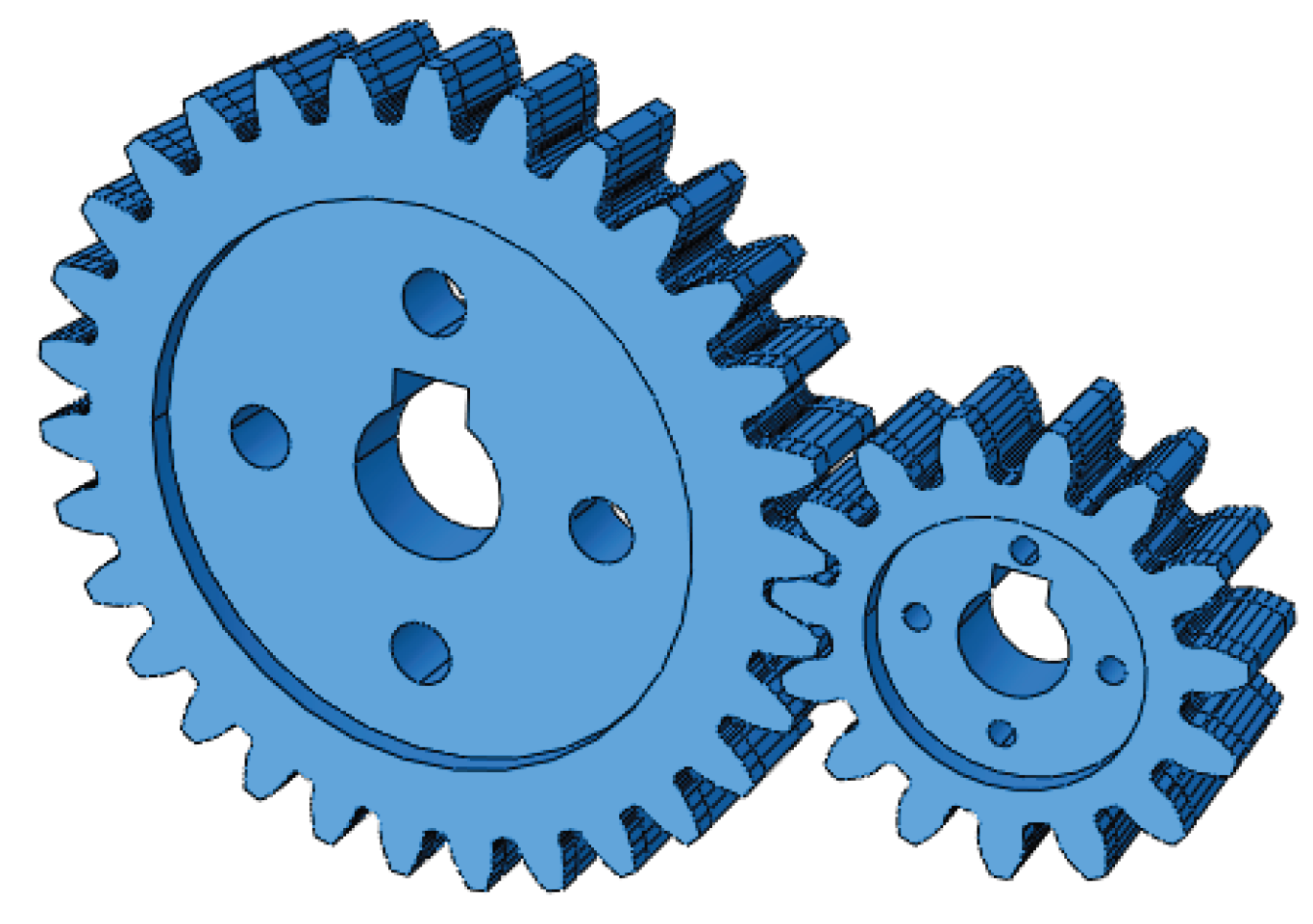
Figure 7.
Finite element model of gear.
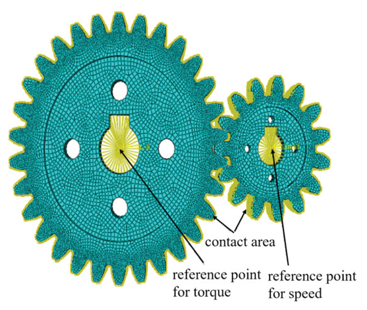
Figure 8.
Curve of driven wheel angular velocity.
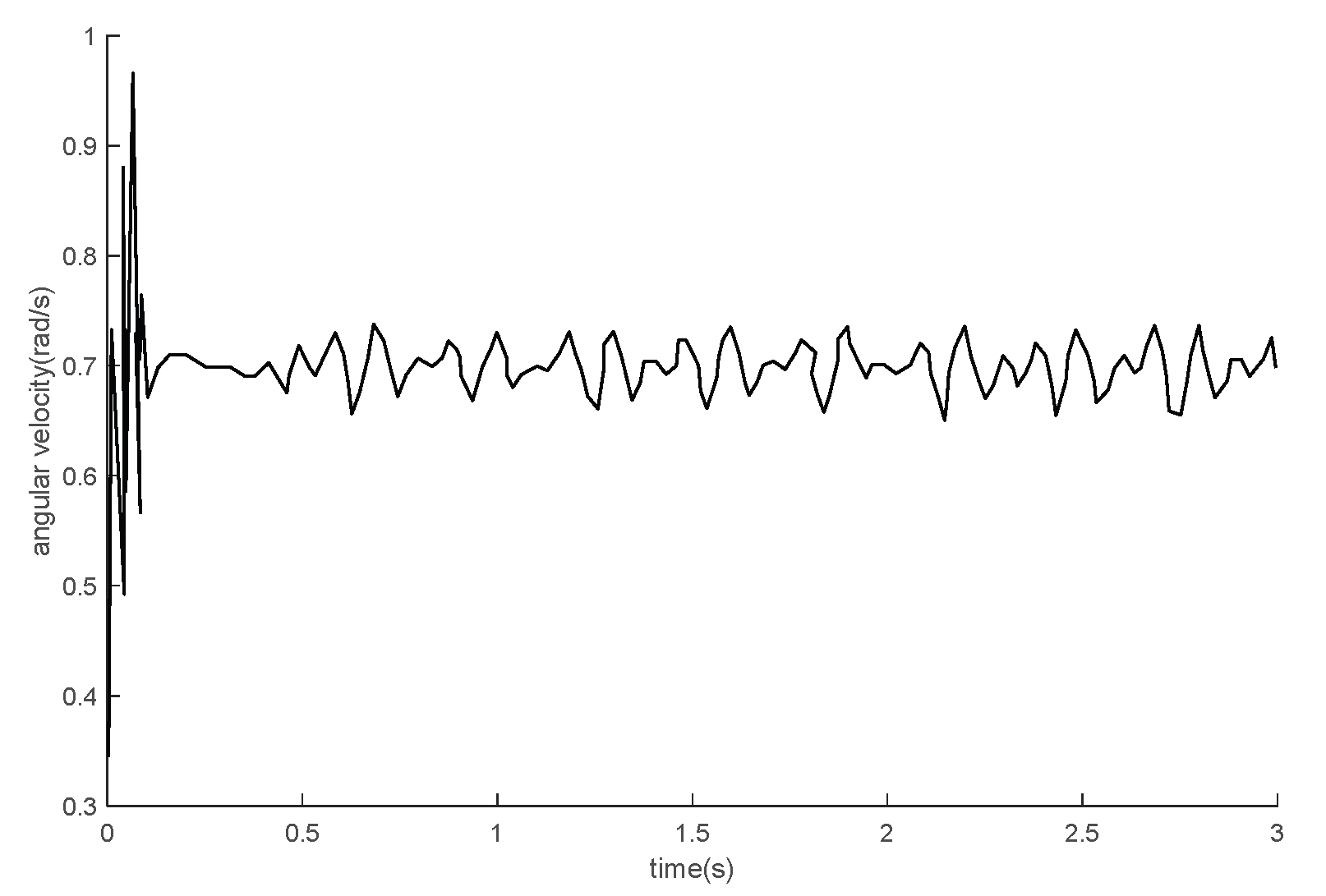
Figure 9.
Curve of contact area.
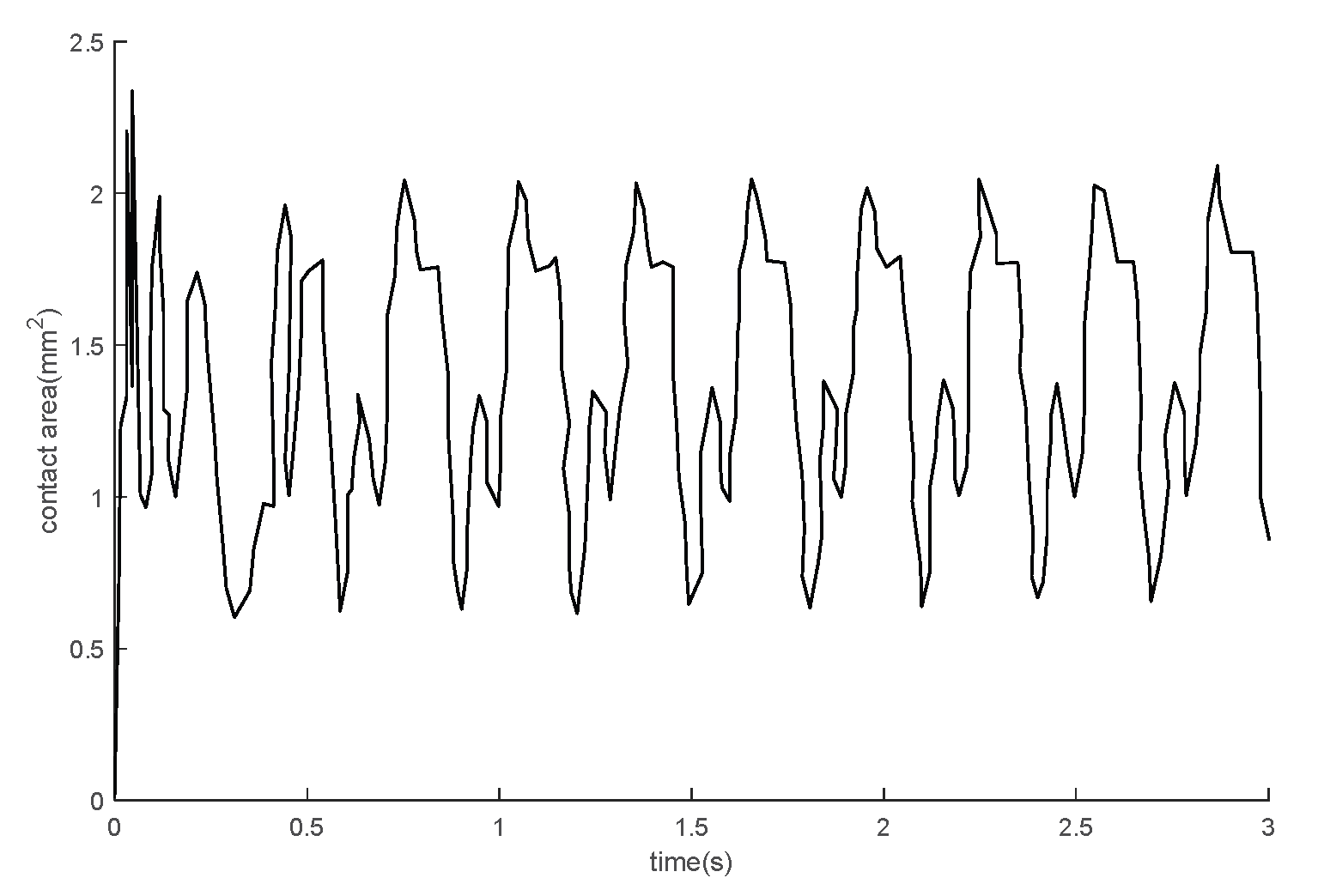
Figure 10.
Curve of contact force caused by friction.
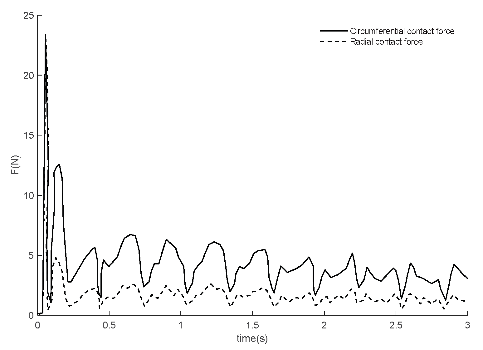
Figure 11.
Stress cloud at different meshing points at different time: (a) 0.1s ;(b)1.5s ; (c)3s.
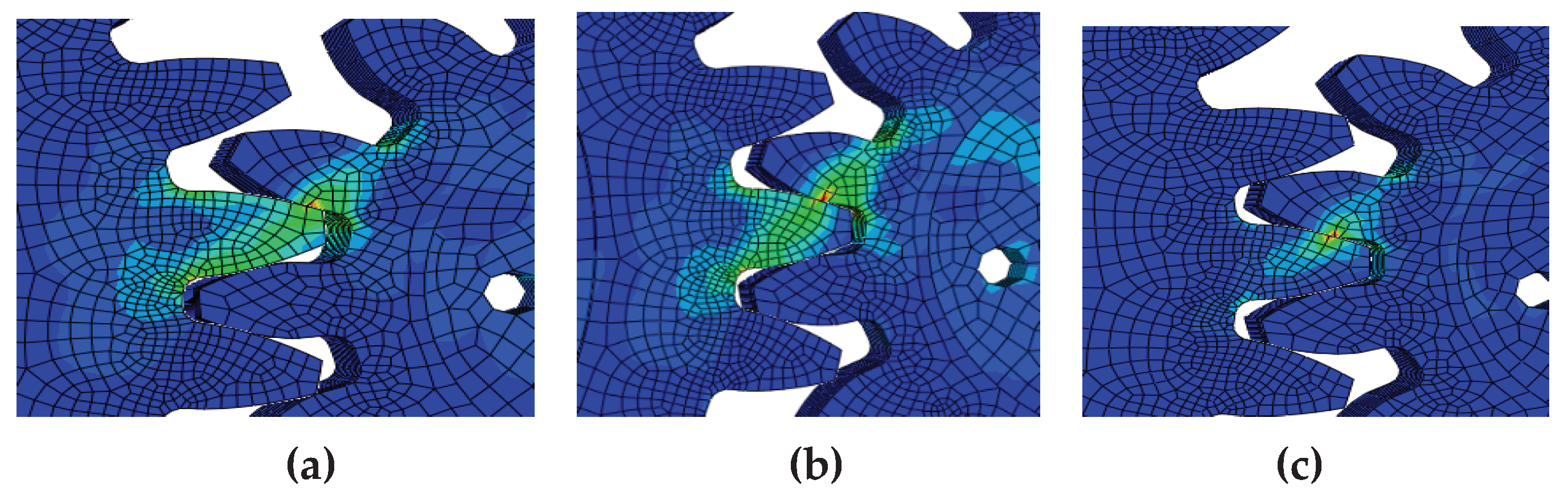
Figure 12.
Stress concentration at the end of the driving gear at different time: (a) 0.15s ; (b)2.5s.
Figure 12.
Stress concentration at the end of the driving gear at different time: (a) 0.15s ; (b)2.5s.
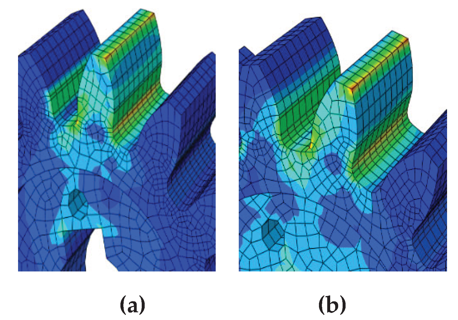
Figure 13.
Equivalent stress of the tooth width direction node at a certain moment: (a)Equivalent stress of driving gear tooth width direction node; (b) Equivalent stress of the driven gear tooth width direction node.
Figure 13.
Equivalent stress of the tooth width direction node at a certain moment: (a)Equivalent stress of driving gear tooth width direction node; (b) Equivalent stress of the driven gear tooth width direction node.
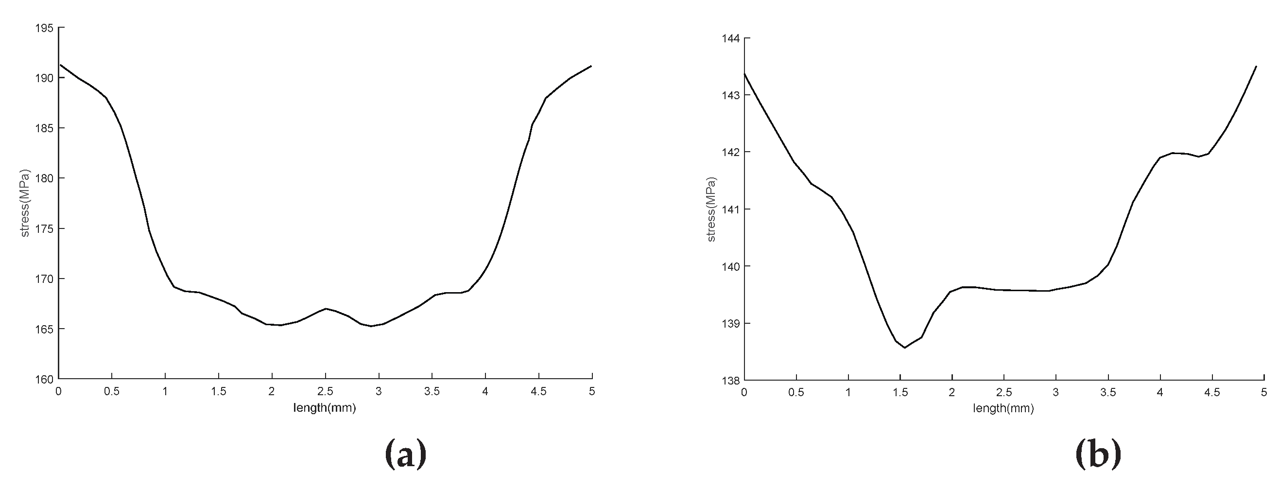
Figure 14.
Finite element model of the outboard wing of a folding wing.
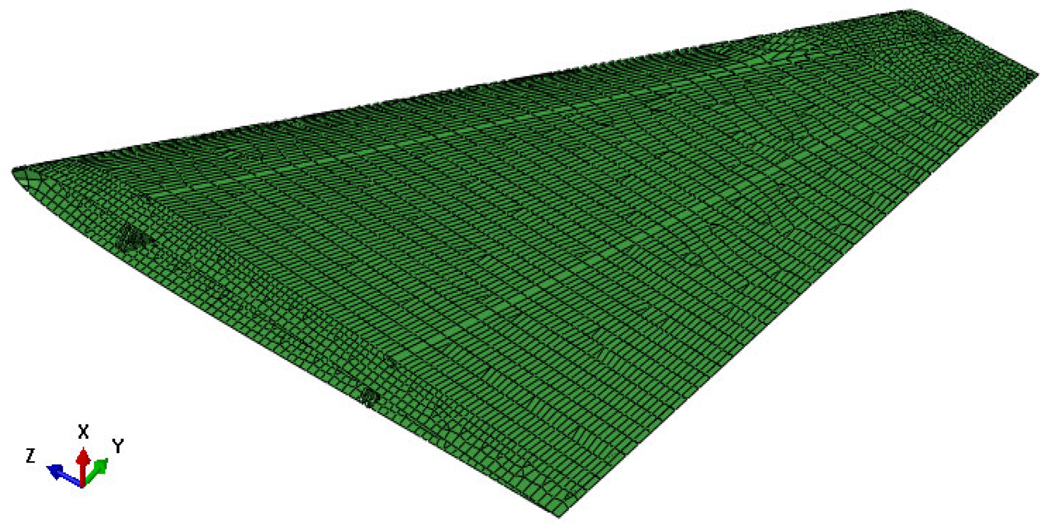
Figure 15.
Local coupling diagram.
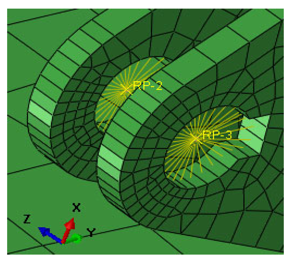
Figure 16.
Load application.
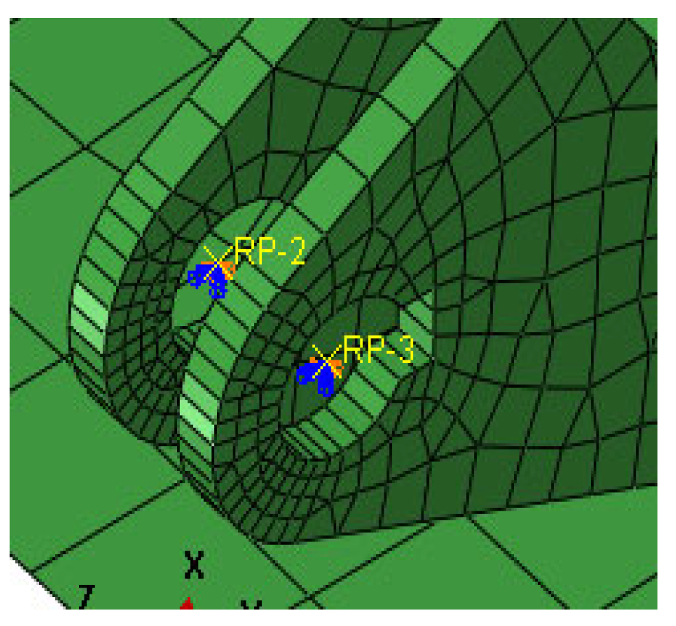
Figure 17.
Stress at the tab at different time: (a) 0.1; (b) 1.5s ;(c) 3s.
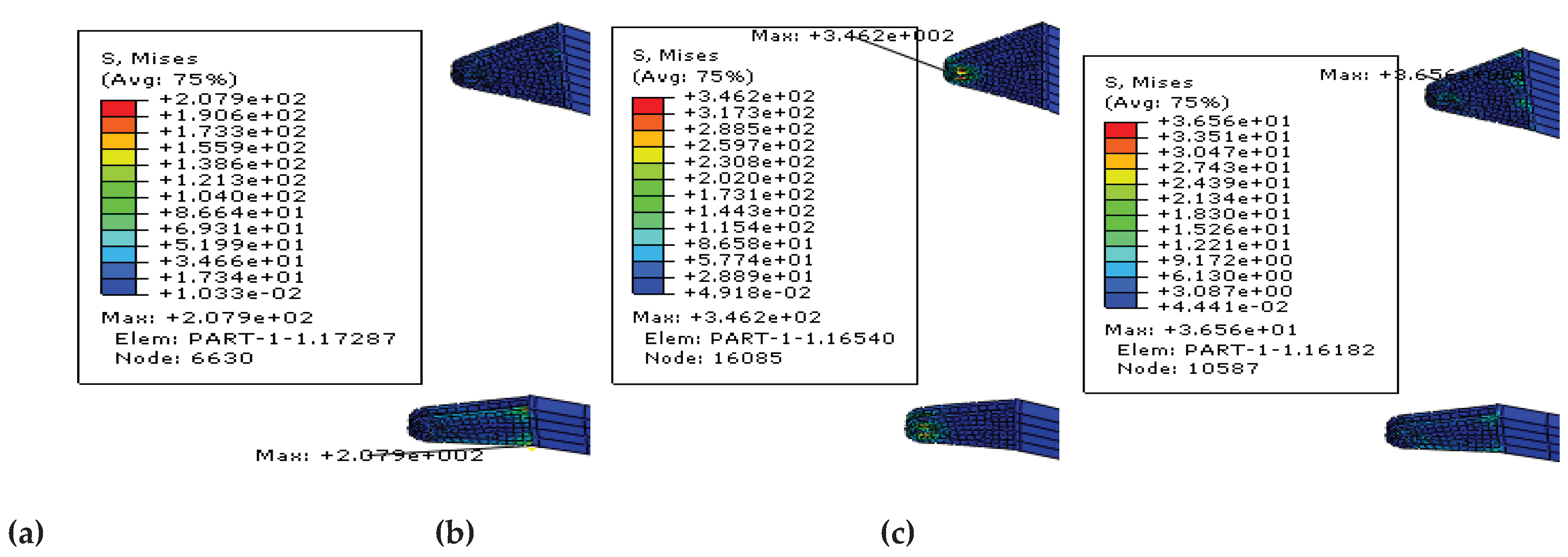
Figure 18.
Displacement t curve at the wingtip.
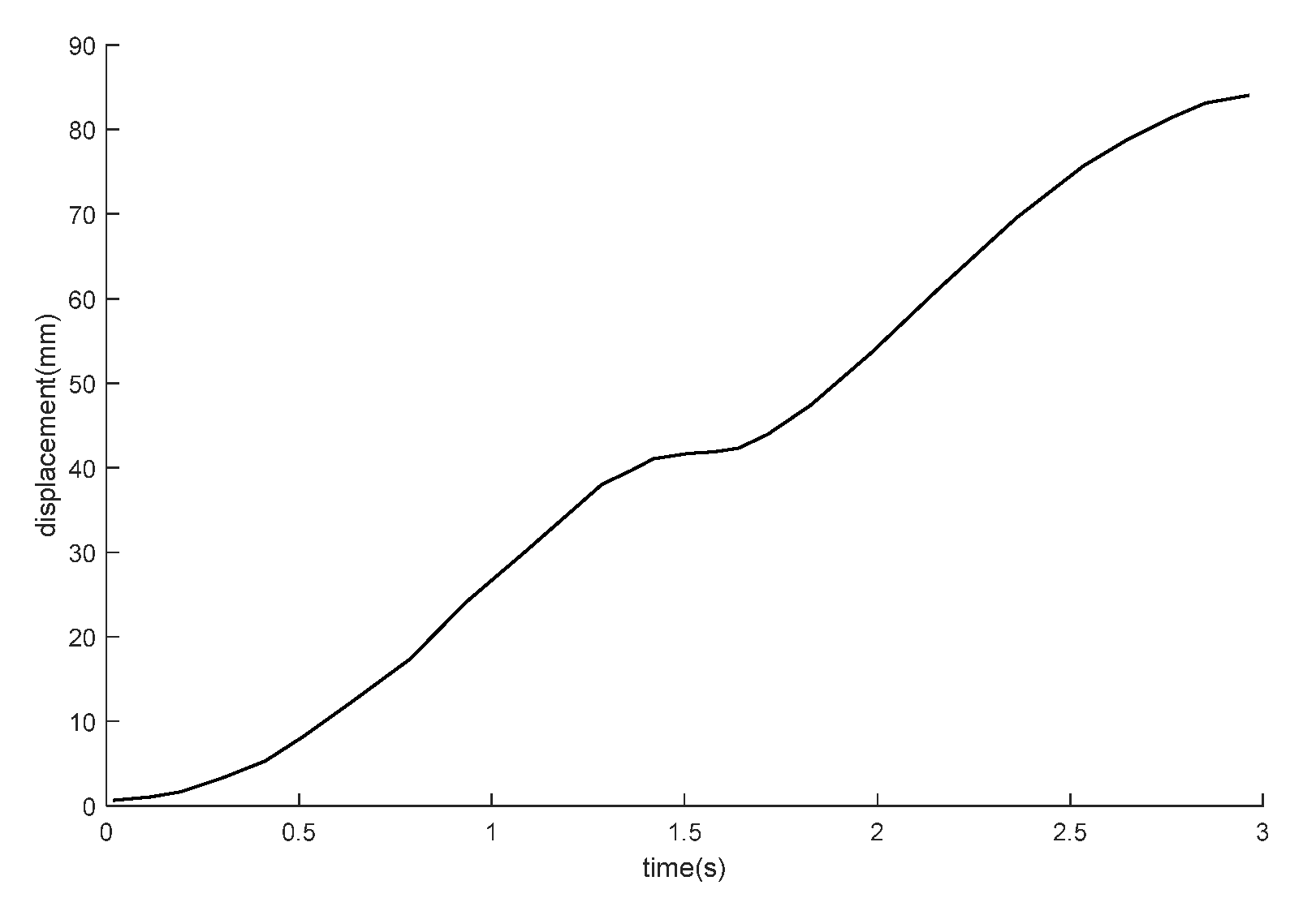
Figure 19.
Topology optimization process.
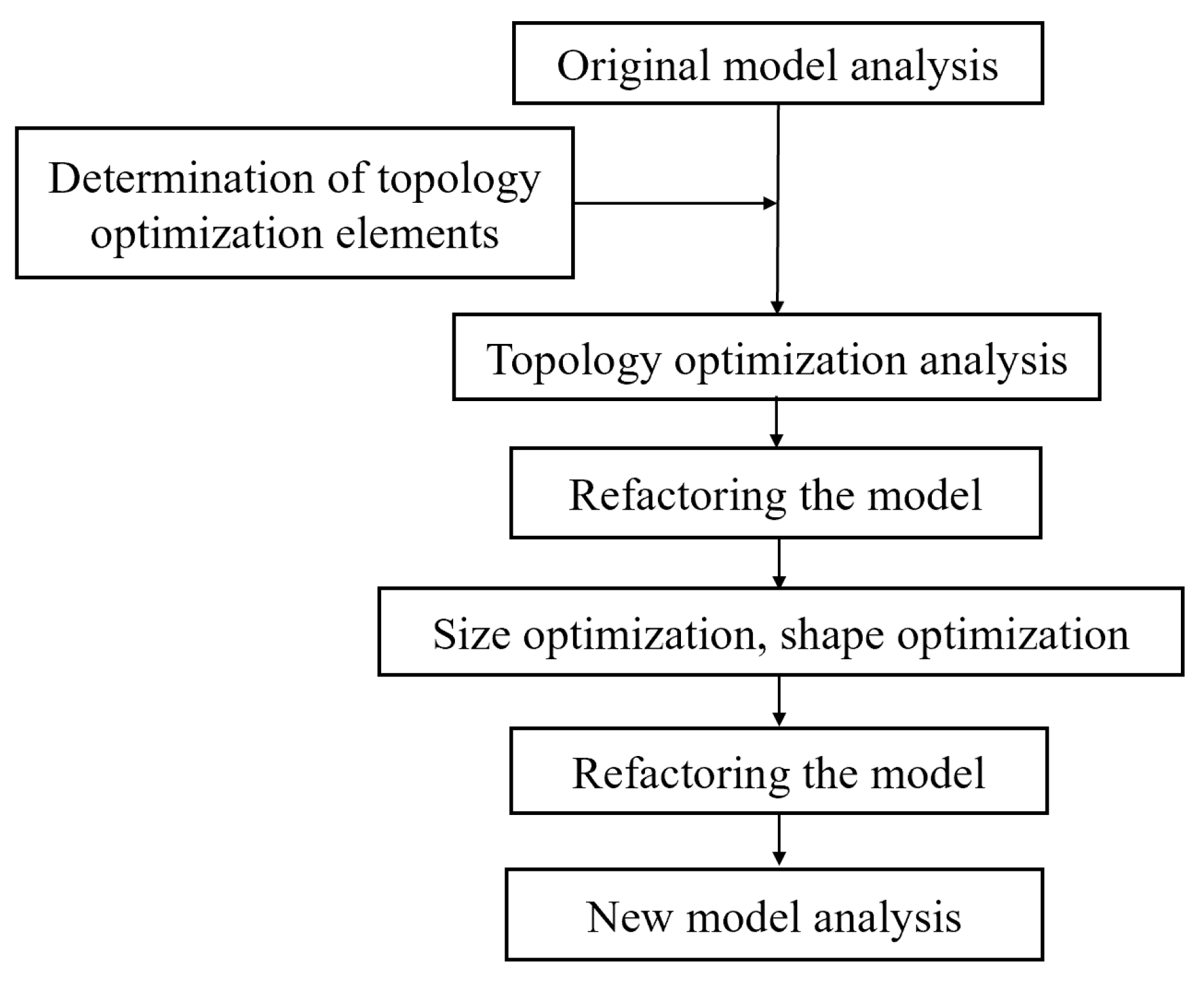
Figure 20.
Load and boundary Conditions.
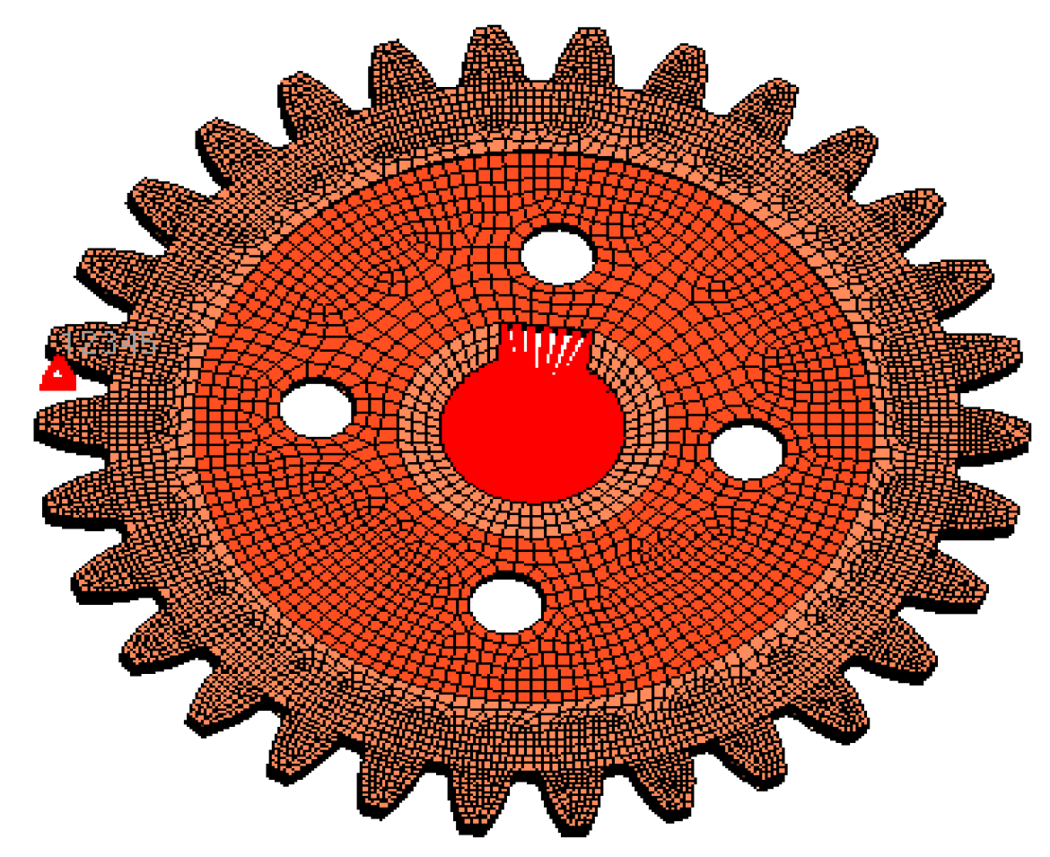
Figure 21.
Optimization Control.
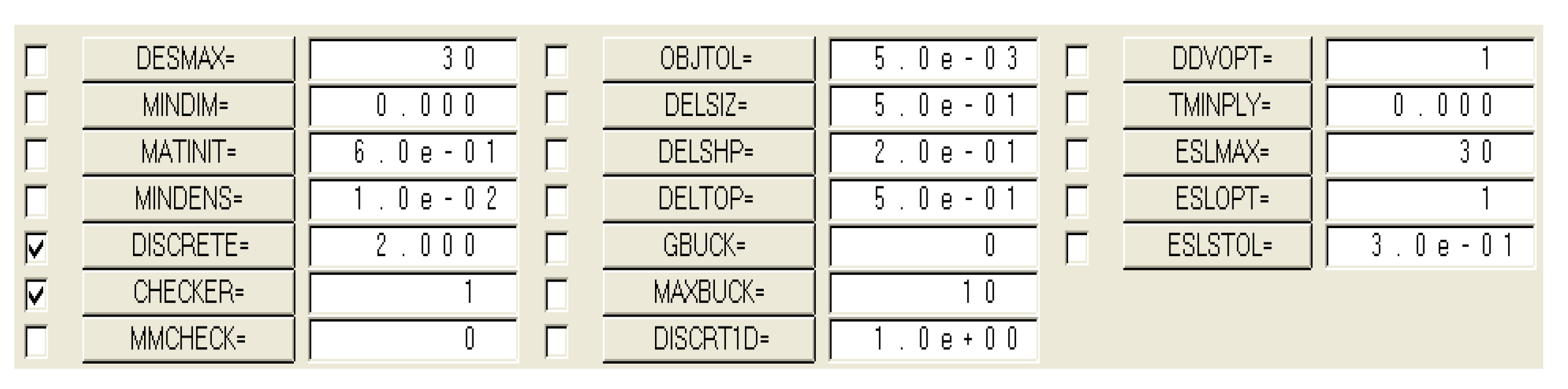
Figure 22.
Material distribution map with a threshold of 0.3.
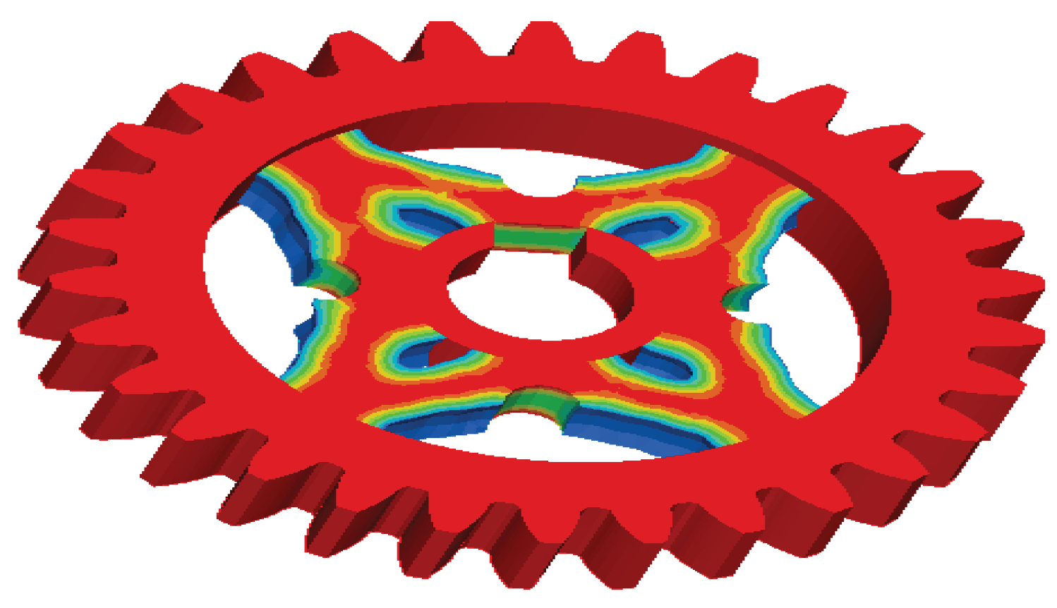
Figure 23.
Element model of wing rib.
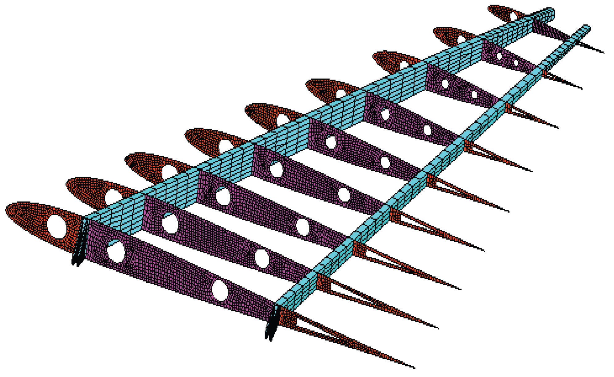
Figure 24.
Load and boundary conditions.
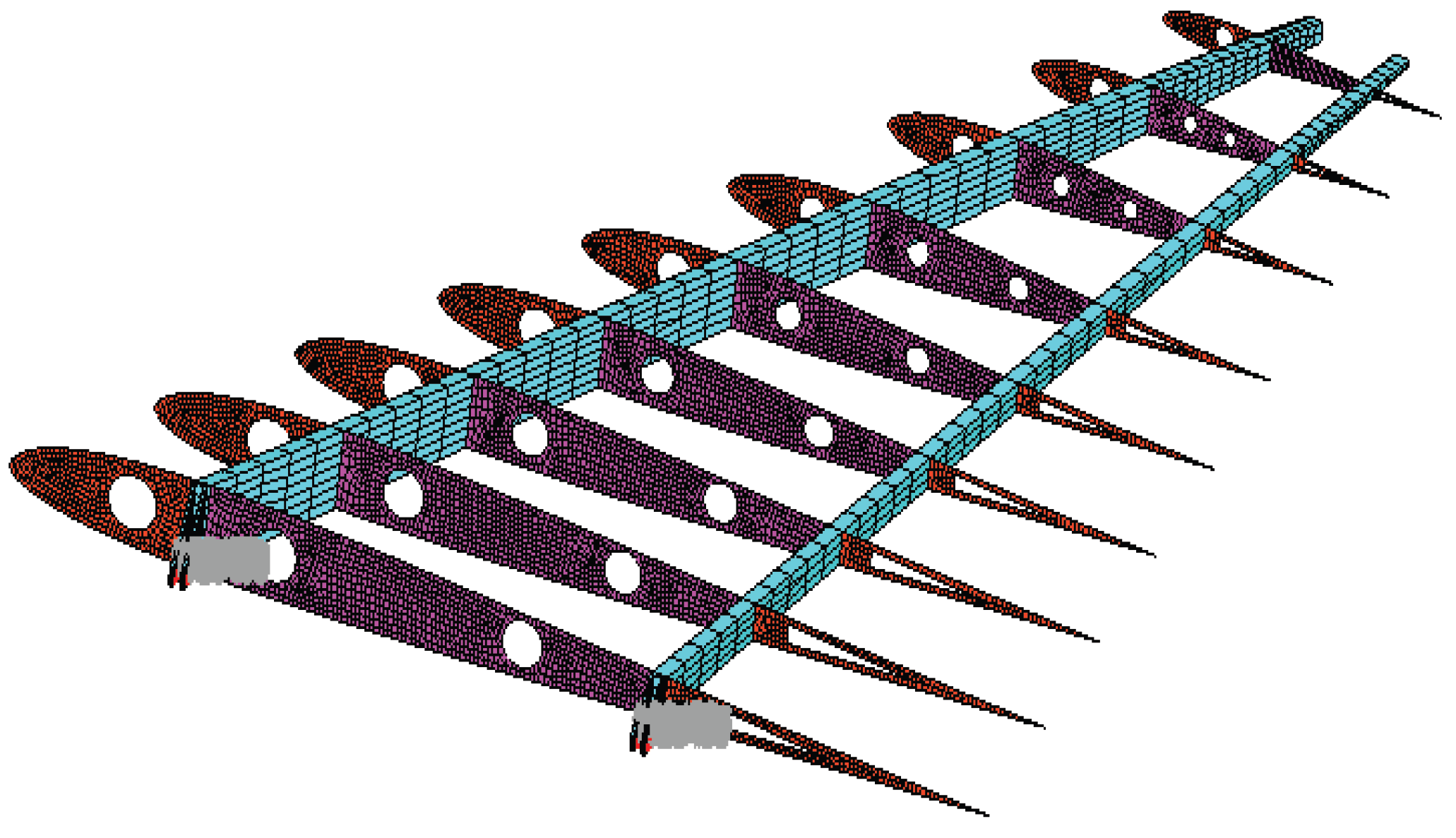
Figure 25.
Static analysis results: (a) displacement contour ; (b) stress contour.
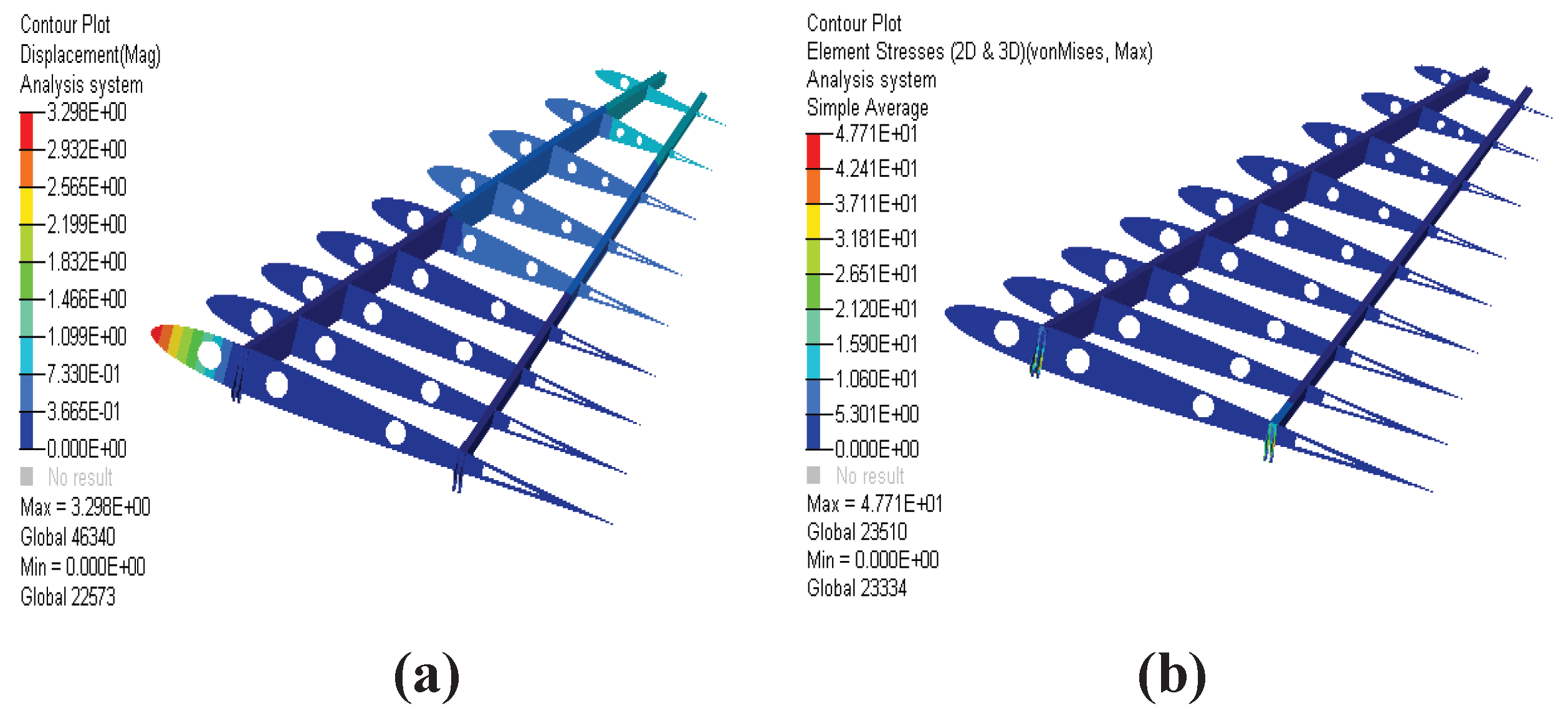
Figure 26.
Mode repetition setting.
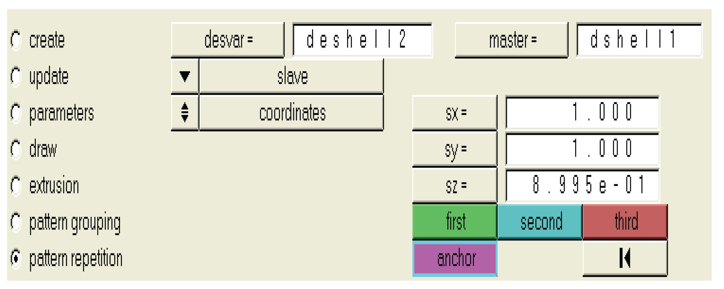
Figure 27.
Density distribution cloud after topology optimization.
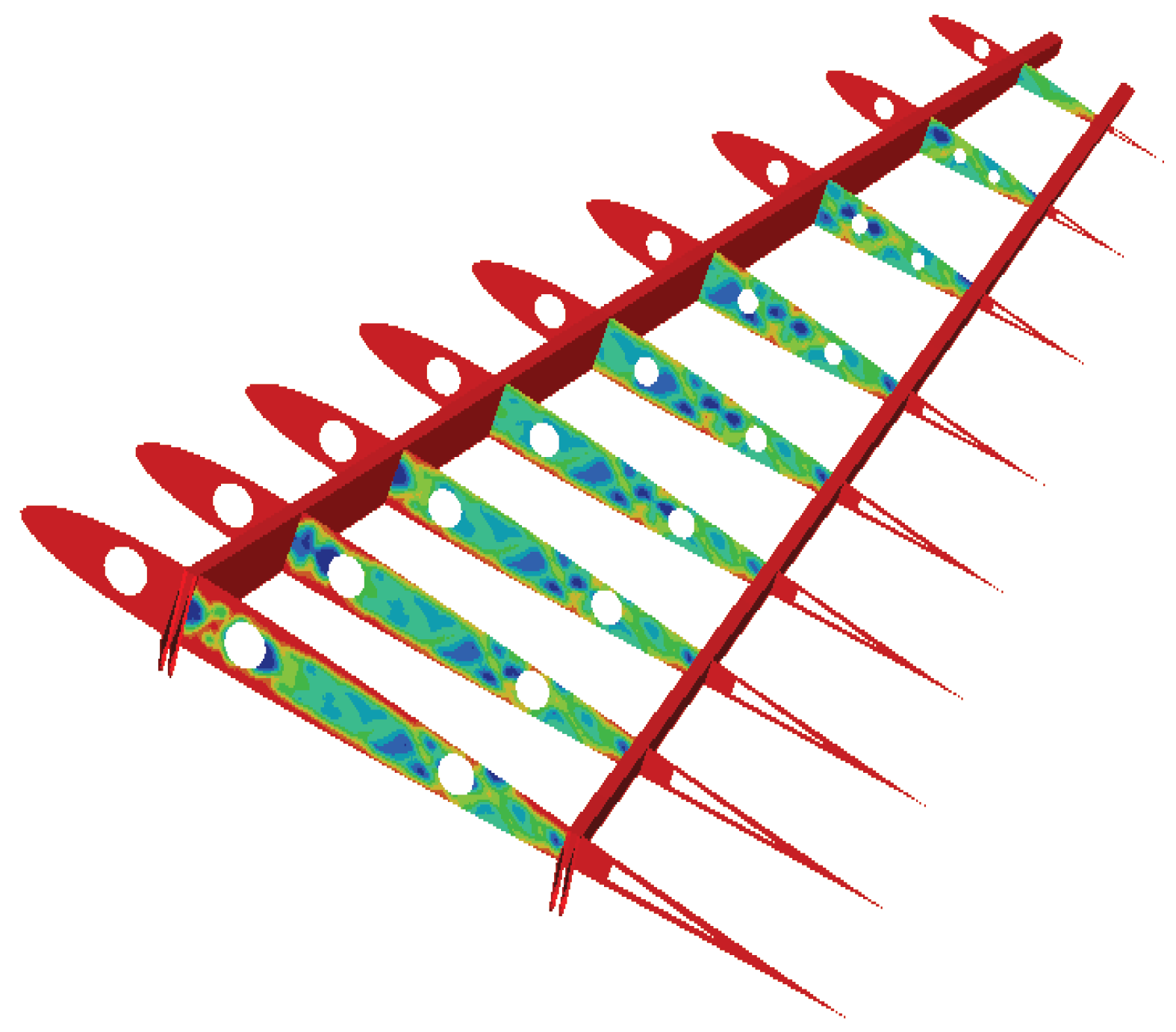
Figure 28.
Material distribution at different density thresholds: (a) Material distribution with a threshold of 0.2; (b) Material distribution with a threshold of 0.3.
Figure 28.
Material distribution at different density thresholds: (a) Material distribution with a threshold of 0.2; (b) Material distribution with a threshold of 0.3.
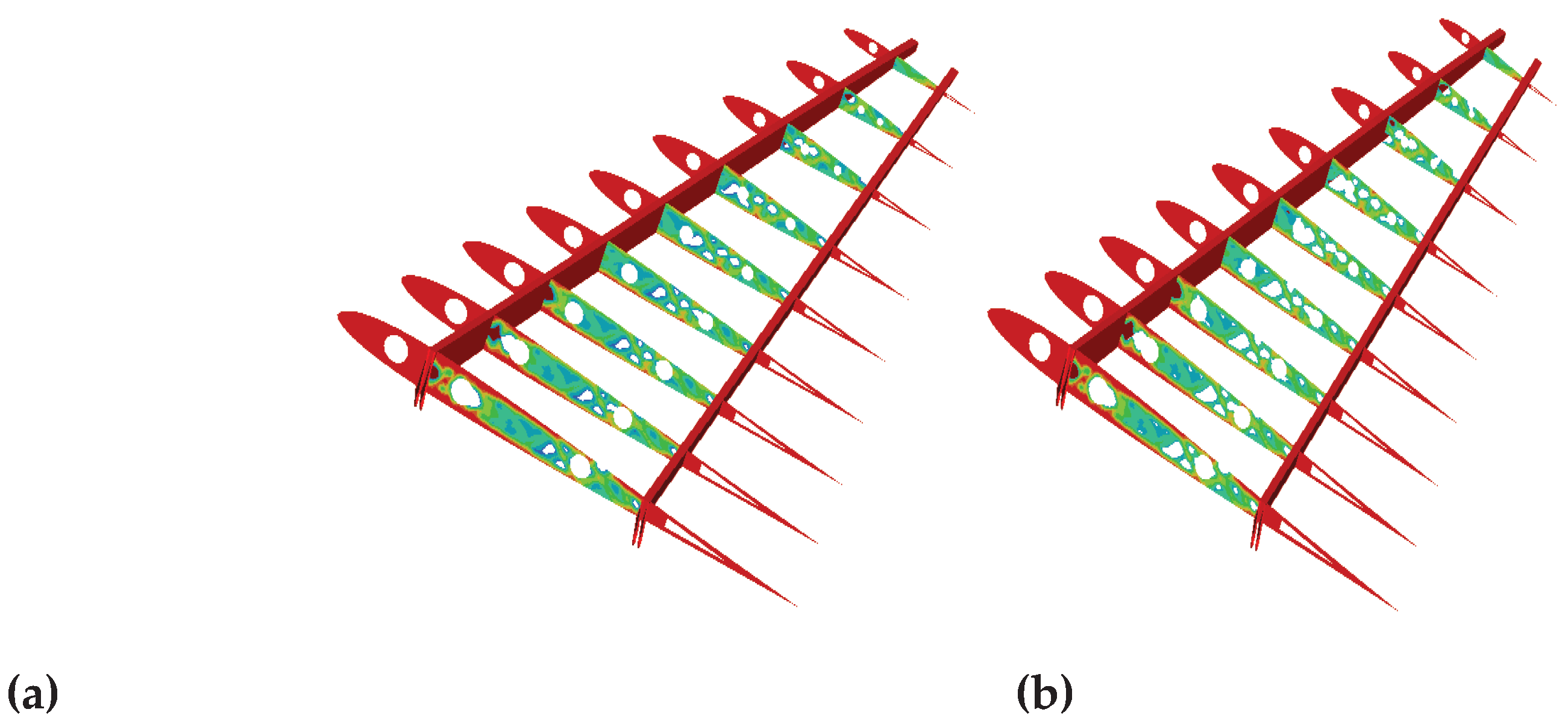

Table 1.
Parameters of each wing segment.
| Name | Span/mm | Root chord/mm | Tip chord/mm | Sweepback angle/° |
| Fuselage | 150 | 1100 | 800 | 45 |
| Inboard wing | 150 | 800 | 550 | 45 |
| Outboard wing | 620 | 550 | 200 | 45 |
Table 2.
Comparison of advantages and disadvantages of different driving method
| Driving method | Advantage | Disadvantage |
| Motor drive | Easy to control, high precision | Low power |
| Hydraulic drive | Low power, small structural size | High hydraulic cost and poor dynamic performance |
| Torsion spring drive | Simple structure | Poor reliability |
Table 3.
Parameters of gears.
| Large gear | Number of Teeth | Modulus/mm | Tooth width/mm | Pressure angle/° |
| 30 | 1 | 5 | 20 | |
| Small gear | Number of Teeth | Modulus/mm | Tooth width/mm | Pressure angle/° |
| 15 | 1 | 5 | 20 |
Table 4.
Material parameters of gears
| E/ GPa | kg/m3 | |
| 210 | 0.3 | 7.85x10³ |
Table 5.
Material parameters of wing.
| Material | Densitykg/m3 | Elastic modulus/Pa | Poisson's ratio | Strength limit/Pa | Yield limit/Pa |
| LY-12 | 2.8×10³ | 7.1×10¹⁰ | 0.33 | 4×10⁸ | 3.5×10⁸ |
| 30CrMn | 7.75×10³ | 2×10¹¹ | 0.3 | 1.078×10⁹ | 8.82×10⁹ |
Table 6.
Material of different component
| Component | Skin | Rib | Beam |
|---|---|---|---|
| Material | LY-12 | LY-12 | 30CrMn |
Table 7.
Response topology optimization 1.
| Response | Response | Response |
| mass | volume | volume/mass fraction |
| center of gravity | moment of inertia | static compliance |
| static displacement | natural frequency | von mises |
| buckling factor | frequency, response displacement, velocity, accelerate | |
| weight compliance | weight frequency | combined compliance index |
| function |
Table 8.
Response to topology optimization 2.
| Response | Response | Response |
| static stress | static strain | static force |
| composite stress | composite strain | composite failure criterion |
| frequency response stress | frequency response strain | frequency response force |
Disclaimer/Publisher’s Note: The statements, opinions and data contained in all publications are solely those of the individual author(s) and contributor(s) and not of MDPI and/or the editor(s). MDPI and/or the editor(s) disclaim responsibility for any injury to people or property resulting from any ideas, methods, instructions or products referred to in the content. |
© 2026 by the authors. Licensee MDPI, Basel, Switzerland. This article is an open access article distributed under the terms and conditions of the Creative Commons Attribution (CC BY) license (http://creativecommons.org/licenses/by/4.0/).
Copyright: This open access article is published under a Creative Commons CC BY 4.0 license, which permit the free download, distribution, and reuse, provided that the author and preprint are cited in any reuse.


