1. Introduction
Ti alloys are important materials used in various fields where high mechanical performance combined with environmental stability and lightness are required. Considering these properties, it is well known their use in aerospace [
1,
2,
3] and biomedical fields for the production of human implants [
4,
5,
6,
7]. In recent years, the increasing interest in the production of components by additive manufacturing process has put Ti alloys at one of the main studied materials, since their manufacture in Near Net Shape (NNS) makes the use of such an expensive material economically sustainable. In fact, with this manufacturing approach, the costs due to material loss are reduced to a minimum [
2].
The mechanical performances of Ti alloys, in particular the Ti-6Al-4V (Ti gr.5), produced by additive manufacturing process have been extensively studied by many researchers, in particular focusing on the microstructure [
8,
9,
10,
11], the internal defects [
12,
13,
14,
15], the anisotropy [
13], the tensile strength and the fatigue resistance [
7,
8,
9,
12,
13,
14,
15,
16,
17,
18,
19,
20,
21,
22,
23,
24,
25]. In terms of production techniques, many studies have focused attention on Electron Beam Melting (EBM) [
17,
26,
27,
28] and Selective Laser Melting (SLM) [
13,
16,
20,
28,
29,
30], where powders of appropriate geometry and size are deposited layer by layer, and between each deposition are melted by a heat source, which can be a laser or electron beam [
22,
31].
In terms of mechanical properties, due to the high mechanical performance required of components manufactured from Ti alloys, fatigue resistance is one of the key properties and it has been extensively studied in the past years. In particular, the effect of both internal defects [
12,
13,
15,
22,
25] and surface texture [
12,
23,
24,
31] on fatigue resistance has been analysed in depth. Masuo et al [
12] described that the most critical internal defects are (gas) pores and lack of fusion. They stated that the presence of detrimental defects predominates in the microstructure of the material itself. They also concluded that the most detrimental parameter in controlling the fatigue resistance of the material is the surface roughness. Shamir et al. [
25] observed that the microstructure of the material and its orientation in the proximity of the internal defect plays a crucial role in the fatigue resistance and in some cases can prevail over the defect size by causing scattering of the fatigue data. Some attempts have also been made to predict fatigue life using numerical analysis based on real CT scans taken on the samples [
30,
32]. In this case, the results are encouraging, although strongly dependent on the CT resolution [
33]. They also observed a strong correlation between the fatigue life and the microstructure in the proximity of the defect, where the size of the α lath determines the crack nucleation of the material. Pessard et al. [
20] also studied the scale effect on the fatigue resistance of the SLM Ti gr.5 alloy. In particular, they observed a slight increase in fatigue resistance due to the probabilistic effect of the defect distribution, which is reduced in small size samples.
Some authors have also investigated the effect of microstructure on the fatigue resistance, for instance a material showing a fine α+β lamellar microstructure can positively impact the fatigue resistance, provided that no internal defects are present [
10,
29,
34]. For SLM samples, the goal is usually achieved by post-printing heat treatments [
19] or Hot Isostatic Pressing (HIP) [
35], which also plays an important role in reducing internal defects [
22,
23,
36]. In the case of SLM it is also necessary to reduce the high residual stresses due to the production process [
19]. In the EBM process, the HIP process can be used to reduce the pores, but usually the microstructure is coarsened due to the acicular shape in the as-printed state [
37]. In general, the control of the α lamella dimension, to obtain a fine size, is necessary to control the fatigue strength of the material [
12,
36,
38].
The effect of surface treatments have been studied to reduce the surface roughness, such as mechanical and chemical surface treatments or machining [
12,
23,
24].
Other researchers have investigated heat treatment processes by including a HIP step prior to the final heat treatment [
36]. The main purpose of HIP was to close the pores and the final heat treatment is to produce the desired microstructure. In the latter case, the strong relationship between mechanical properties and microstructure was observed by producing a fine α+β lamellar microstructure after a complete solubilisation step.
Surface treatment has also been the subject of research by many authors investigating the fatigue resistance of the additive manufactured Ti alloys [
9,
38,
39,
40]. In this case, any surface treatment that greatly reduces the severity of the printed surface is a benefit to fatigue life. Most of the researchers showed that simple machining of the as-printed surface increased the fatigue resistance of the material, some authors also introduced some treatments to induce compressive stresses [
38] on the surface such as shot peening or tumbling [
9]. The negative effect of the surface on fatigue resistance has generally been related to the high roughness of the printed materials and also to the layered structure of the printed sample [
31]. In all cases the surface acts as a series of small notches which can act as stress raisers.
The main goal of this study is to characterize Ti6Al4V material produced by EBM and SLM processes from the point of view of fatigue performance by considering the surface finish, thermal and thermomechanical treatment effect. The aim of this work is to evaluate the fatigue resistance of the Ti6Al4V alloy through a comprehensive experimental methodology, incorporating the analysis of potential crack initiation sites, including surface morphology, microstructural characteristics, and internal defects. The study compares two additive manufacturing processes, assessing their influence on the alloy’s mechanical performance as a function of both intrinsic material properties and applied post-processing treatments. The fatigue results, and in particular the failed samples, are deeply investigated in order to seek for correlations of the defects that nucleated the fracture on the fatigue resistance of the material.
2. Materials and Methods
2.1. Sample Design and Preparation
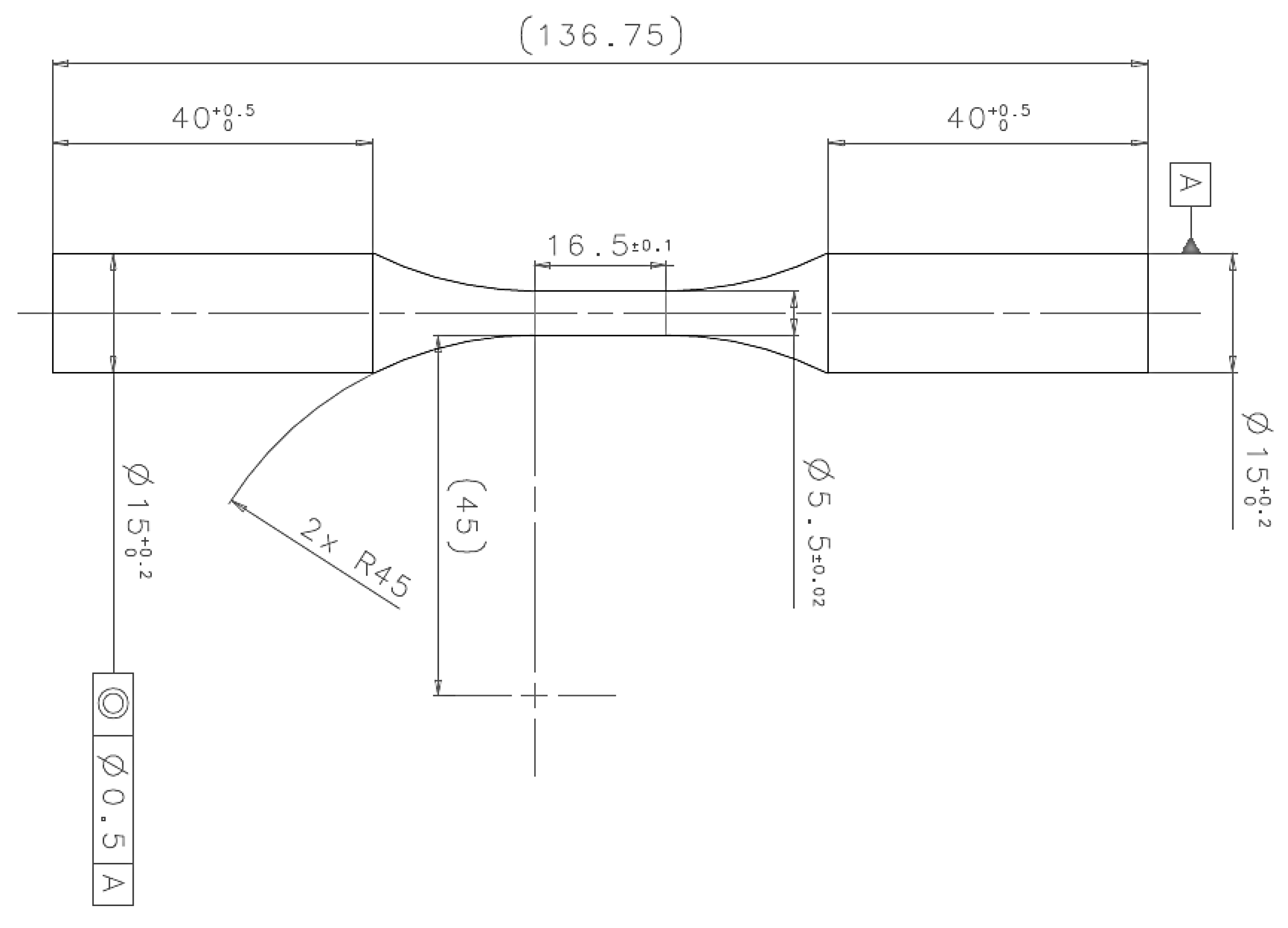
The specimen geometry adopted for the fatigue tests in this study, illustrated in
Figure 1, was designed in accordance with the ASTM E466-15
Standard Practice for Conducting Force Controlled Constant Amplitude Axial Fatigue Tests of Metallic Materials [
41]. A total of 100 samples were produced in a single build for the EBM technology and total of 100 samples were produced in four different builds for the SLM technology. For EBM technology, two different surface finishing (as-printed and machined) and two microstructural conditions (NO-HIP and HIP) were investigated. For the SLM technology two different surface finishing (as-printed and machined) and two microstructural conditions were investigated (VHT and HIP). The SLM samples underwent stress relief treatment in vacuum (VHT) in order to both slightly modify the microstructure and relief the internal stresses induced by the SLM process [
42,
43]. In addition, the treatment should modify the microstructure of material in order to fulfil the tensile test results requirements according to ISO 5832-3:2021 I
mplants for surgery - Metallic materials - Part 3: Wrought titanium 6-aluminium 4-vanadium alloy [
44]. The heat treatment was performed in vacuum following an recipe developed in LimaCorporate. For the SLM specimens, the NO-HIP conditions indicated in the work corresponds to a stress relieved condition. The HIP treatment is compliant to ASTM F3001-14(2021)
Standard Specification for Additive Manufacturing Titanium-6 Aluminum-4 Vanadium ELI (Extra Low Interstitial) with Powder Bed Fusion [
45].
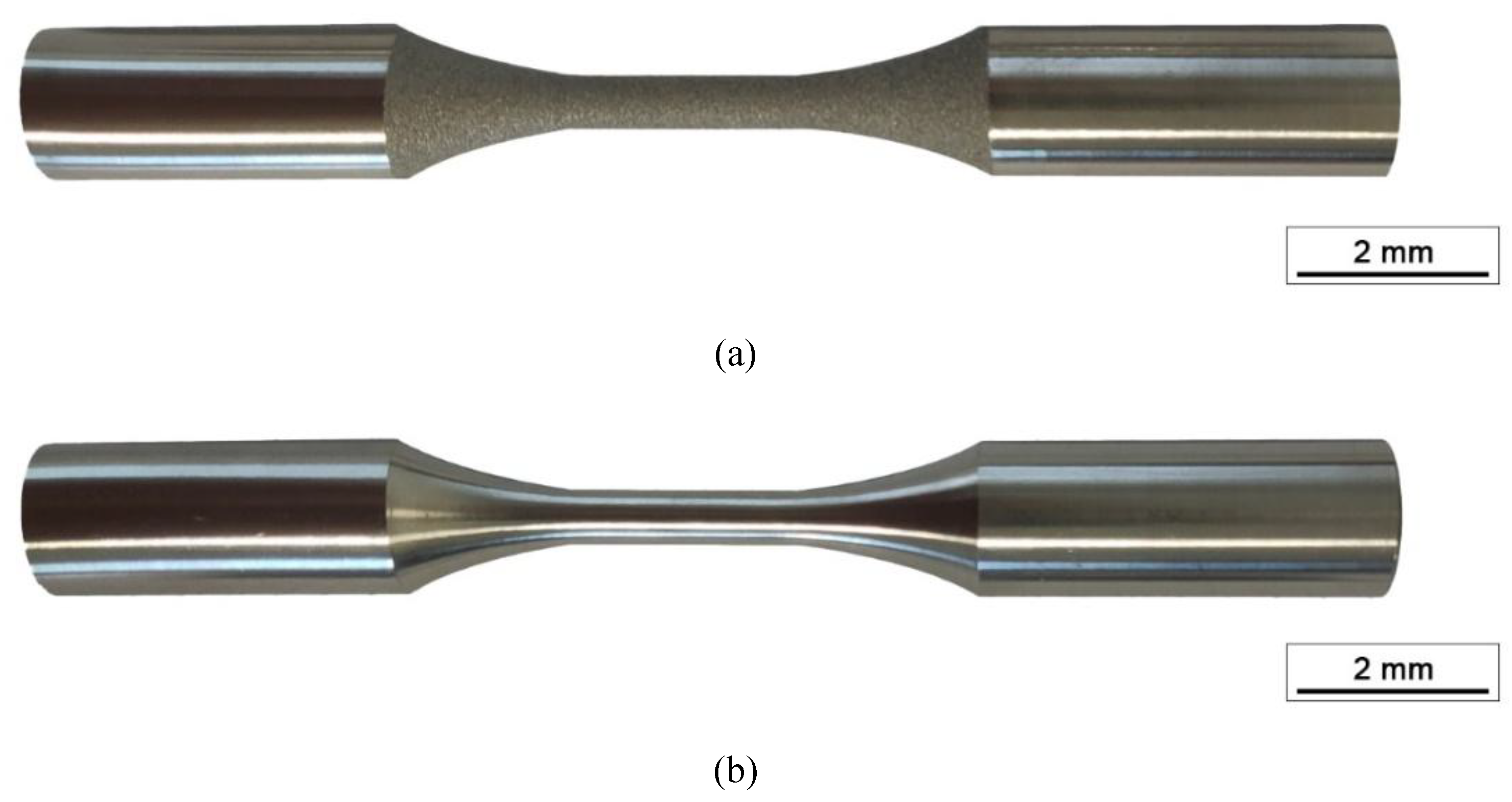
A representative example of the surface finish obtained on the analysed samples is presented in
Figure 2, while the different processing conditions investigated in this study are summarised in
Table 1.
For both technologies, EBM and SLM, the samples were produced with a vertical orientation in respect to the building plate, that usually is the printing direction with the lower mechanical resistance of the material [
46,
47]. All batches were subjected to dimensional tests according to the specific drawings and a degreasing washing step before being made available for mechanical testing. Each build includes dedicated test coupons to characterise the material in different thermal conditions (NO-HIP and HIP). Traceability of each sample was maintained throughout the production chain by micro-milling marking of the gripping head.
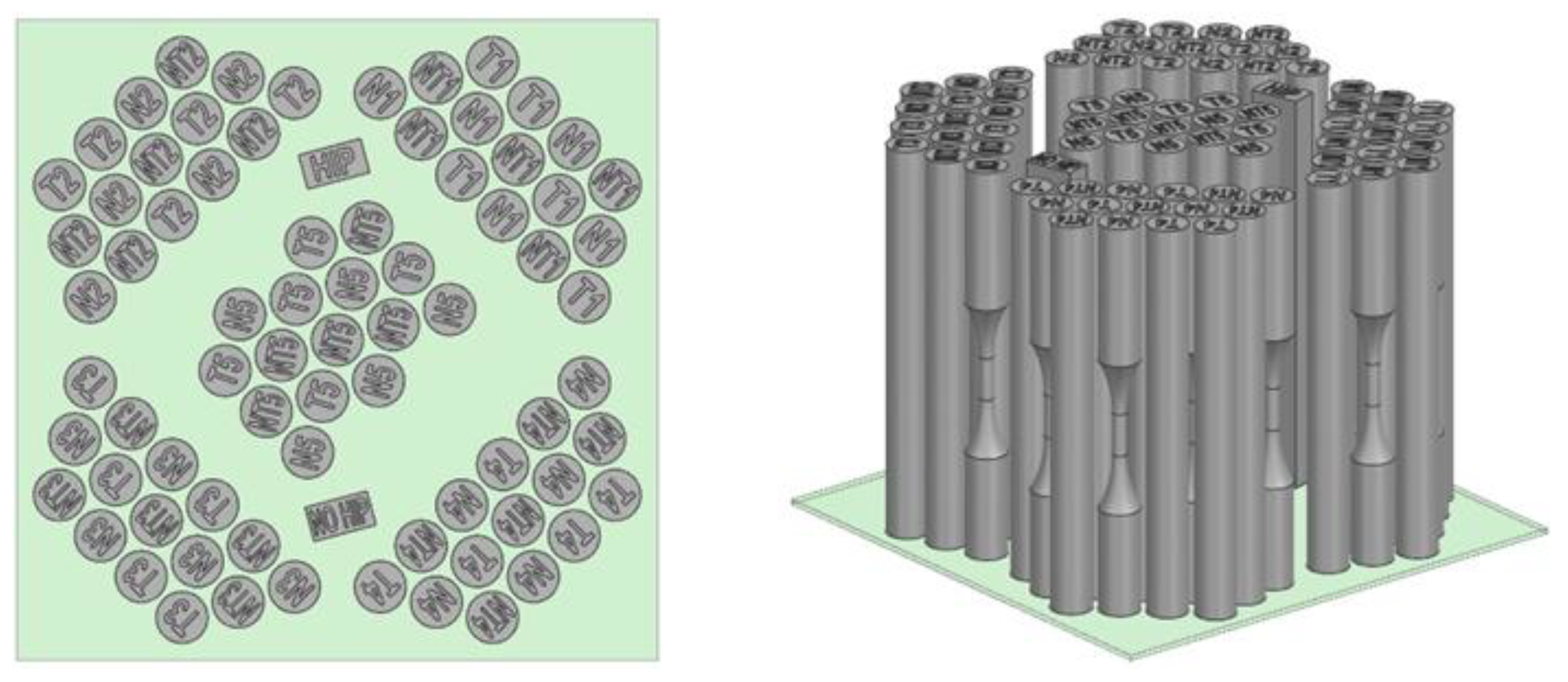
Machine model and printing conditions are summarized in
Table 2 and
Table 3 for EBM and SLM technology respectively. The process parameters (normally called melting themes) are invariant along the samples production. The available print volume has been divided into five zones, one central and four at the perimeter, as reported in
Figure 3. Five samples for each different condition in each area were manufactured, for a total of 25 samples for each build. An illustrative build layout used for this study is reported in the same figure.
2.2. Microstructural Characterization
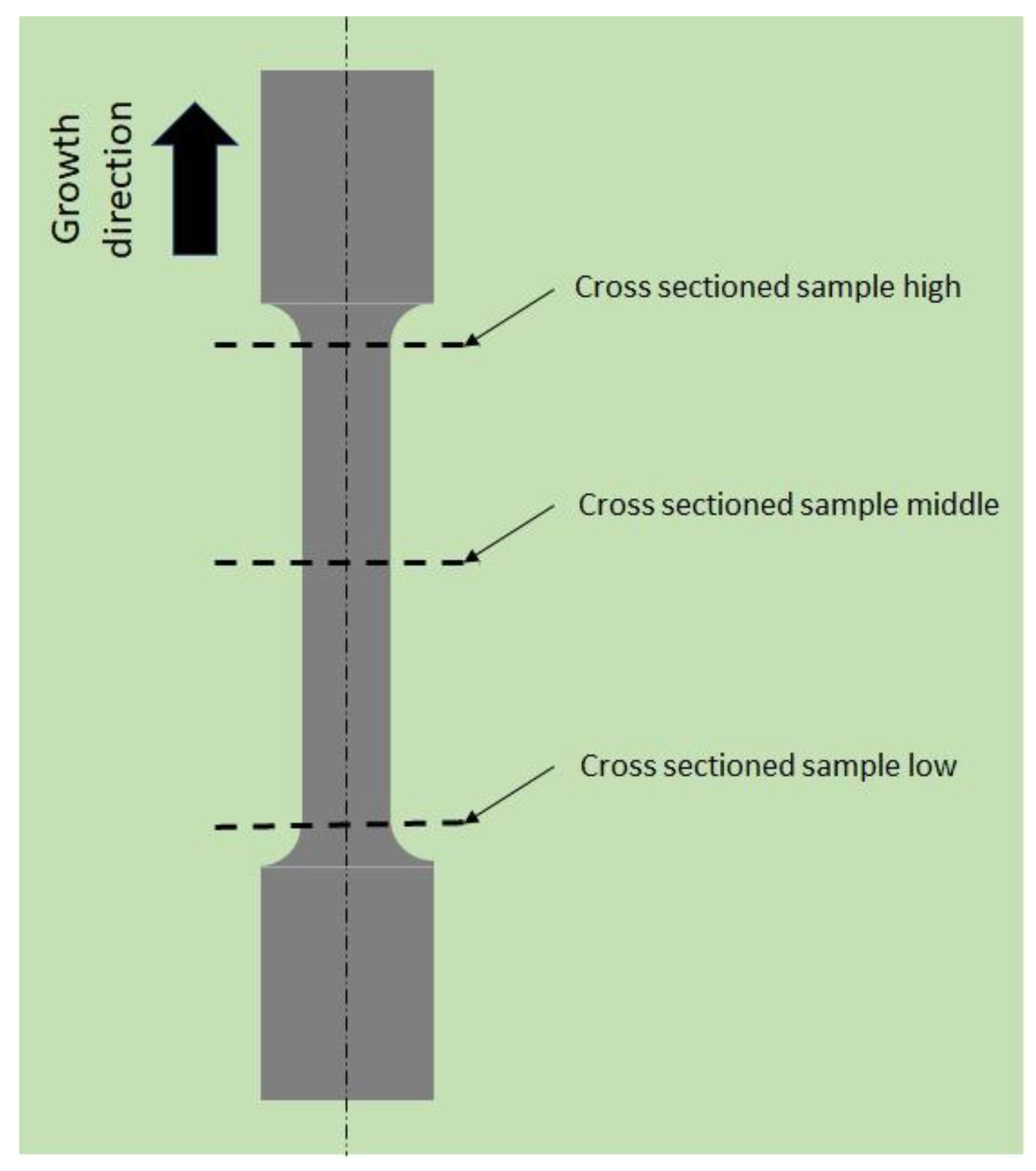
A detailed microstructural and mechanical characterisation was performed on the samples. Two samples for each heat treatment condition and printing technique were used for the microstructural analysis. A detail of the sample extraction is shown in
Figure 4.
The extracted samples were embedded in epoxy resin and then subjected to a standard metallography preparation in order to obtain a mirror like surface. The prepared cross-section samples were subjected to a size and defect distribution analysis, performed by light microscope on five different analysis areas of each sample. The samples were then etched using Kroll’s reagent (100 ml deionized water mixed with 3 ml of hydrofluoric acid and 3 ml of nitric acid) for 60 sec. Subsequently, the etched microstructures were examined using a Zeiss Axio Vert.A1 optical microscope. The β-phase content and α-phase grain size were determined via phase analysis and the linear intercept method, respectively. Quantitative image analysis was performed using Zeiss ZEN core software.
Subsequently, the previously characterised samples were subjected to further metallographic preparation to obtain a suitable surface finish for microhardness mapping. In the cross sectioned samples, a polar HV0.3 pattern was used in order to have a circumferential and radial spacing of 0.25 mm between each indentation. A total amount of 257 points were collected for each sample and the results are presented in 2D parametric graphs. The average microhardness value ((HV) ̅) of the cross sectioned sample (HIP machined EBM) extracted from the central region, for each heat treatment condition was used to a-dimensionalize the mechanical properties used in this work according to the following equation:
where ∆σ represent the difference between the maximum and the minimum value of the applied stress in the specific condition.
The surface texture of the samples in the as-printed condition was analysed in the same three different sections shown in
Figure 4. The measurements were carried out by following these procedures:
acquisition of a EDF (motorized focus) image via a Zeiss Axio Zoom V16 optical stereoscope at a 50x magnification, with a PlanNeoFluar Z 1x/0.25 FWD 56 mm lens and slice thickness equal to 1 µm;
post-processing of the raw image with the surface analysis workbench of the software
ConfoMap 8.0, using the Minidoc for the profile extraction and select the right λs (25 um) and λc (8 mm) filters as for ISO 21920-3 2021 Geometrical product specifications (GPS) —
Surface texture: Profile - Part 3: Specification operators [
48];
extrapolation of the surface characteristics via colour maps and quantitative data combined with a table where are listed all the surface and linear metrics (Ra, Rt, Rz).
The surface properties of machined specimens was evaluated by means of Veeco Dektak 150 stylus profilometer with five scans for each sample along the growth direction, in accordance to ISO 21920-3:2021
Geometrical product specifications (GPS) — Surface texture: Profile - Part 3: Specification operators [
48]. The acquired data was the same of as-printed surfaces (Ra, Rt, Rz).
With the surface data characterization the Kt (Kf) factor was evaluated as indicated by Arola et al. with the following equation [
49,
50]:
To calculate , the longitudinal samples were analyses in proximity of five deeper surface notches.
2.3. Static Tensile Tests
Static tensile tests were conducted to characterize the properties of the material under investigation according to ISO 5832-3:2021
Implants for surgery - Metallic materials - Part 3: Wrought titanium 6-aluminium 4-vanadium alloy [
44]. In particular, the specimens are the same used for the fatigue characterization. The tensile tests were performed in mixed control mode: strain control up to a strain of 2% and displacement control up to rupture. The strain rate used was 0.5 (mm/mm)/min and the displacement rate was 5 mm/min. The YS, TS and E% were acquired for each analysed specimen.
2.4. Fatigue Tests
Fatigue tests were performed on a minimum of 12 samples for each batch presented in the previous paragraph. The experimental condition for the fatigue tests consisted of applying an uniaxial load with R=0.1 and a frequency of 40 Hz with a run-out reached at 10^7 cycles, also identified as the fatigue endurance limit. A staircase approach was used and the initial load was determined from the scientific literature review [
51,
52]. After each failure or run-out event, the applied load was varied by ± 20 MPa. The data obtained were plotted to an S-N diagram and the fatigue limit was calculated using the Dixon Mood approach [
53]. Some run-out samples were retested at significantly higher stress amplitude to partially populating the High Cycle Fatigue regime of the S-N curve. All the data obtained were presented in dimensionless plots for the stress-related data. The failed samples were analysed by SEM to obtain information on the crack initiation point and the area of the crack nucleation defect [
55].
3. Results and Discussion
3.1. Microstructural Characterization
The evaluation of the internal defects content and distribution is a key information to better understand the fatigue behaviour of the material and also to evaluate the accuracy of the printing parameters. In
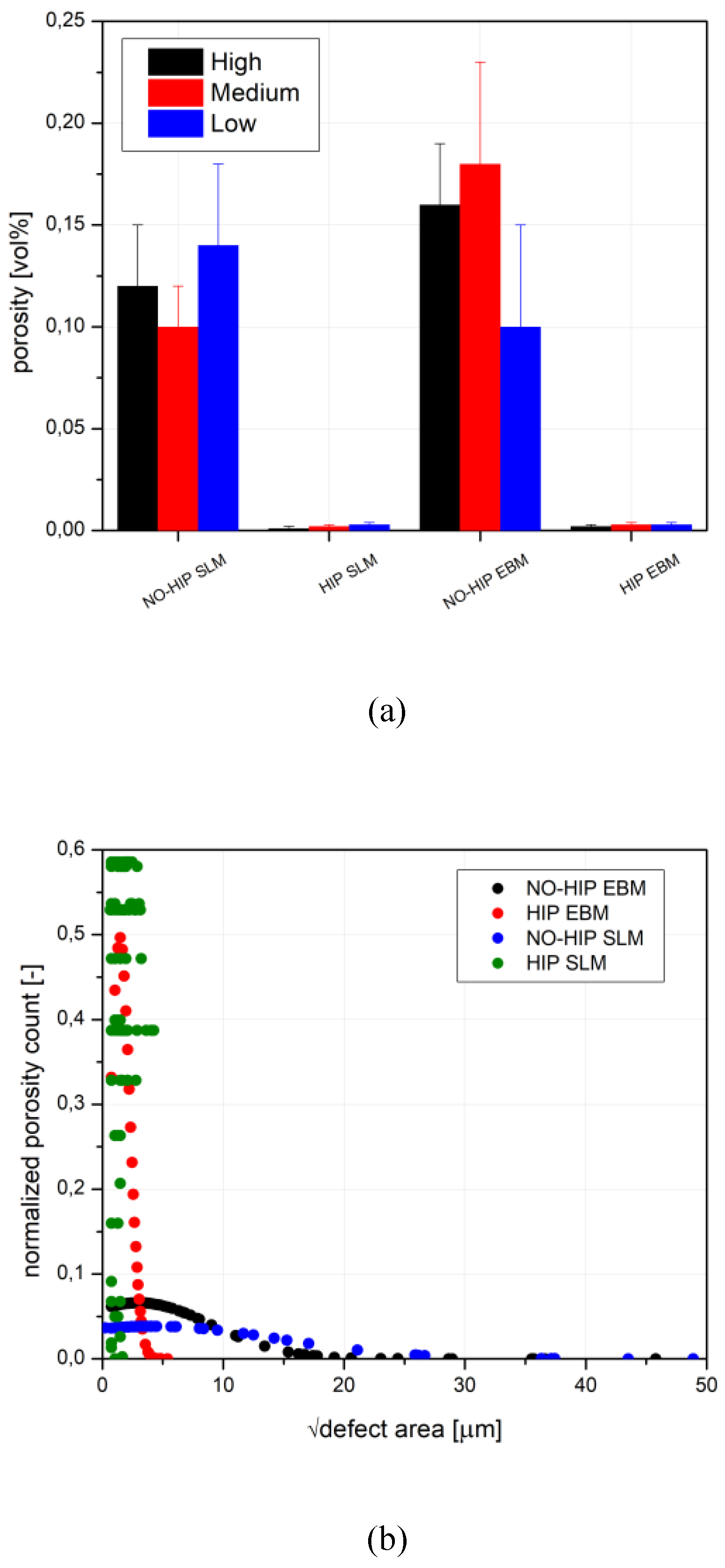
Figure 5 the volumetric content and the relative internal defects distribution are shown for all batches analysed with different postprocessing treatment conditions (NO-HIP and HIP). The volumetric content, as shown in
Figure 5(a), reveals that the SLM sample in as-printed condition (VHT) is similar to the EBM ones. Possible variations of the volumetric content as a function of the analysed area may be correlated to measurement errors rather than process parameters, due to the small differences found between each analysed sample. On the other hand, the HIP treatment strongly reduced the internal defects in both the analysed samples to levels near to zero. The detected defects are mainly labelled as spherical pores and lack of fusion defects [
17]; the latter are less in number as compared with the pores but larger in characteristic size.
The internal defects size distribution, as shown in
Figure 5(b), shows a broad range for the as-printed samples with defect sizes ranging from a few µm to hundreds µm. The EBM samples, when compared to the SLM ones, show a broader distribution with defects of slightly higher dimension.
In both samples, the HIP greatly reduced the distribution of defects, becoming narrower in the proximity of small circular pores, which are also likely to be confused with the background noise of the image analysis. It can be stated that, for both technologies, the post-HIP situation is totally comparable when referencing internal defects. This agrees with the analysis of other authors [
54].
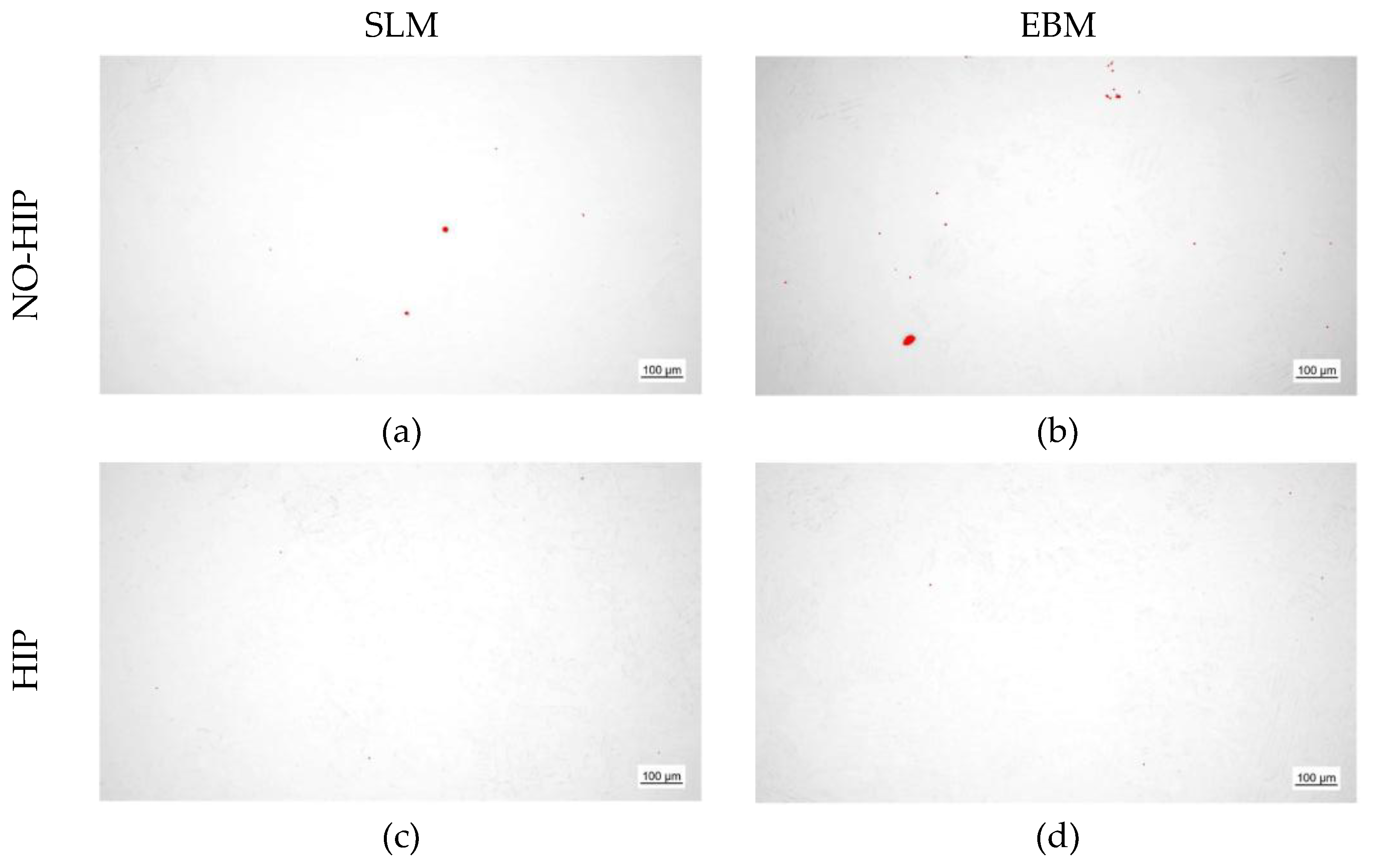
Figure 6 shows that the red areas are mainly pores, some of them elongated. The porosity is barely visible in samples that underwent to HIP. This is in agreement to what expected from material treated by HIP.
The microstructures of the analysed samples are shown in
Figure 7, for samples in NO-HIP condition, and
Figure 8, for samples in HIP condition.
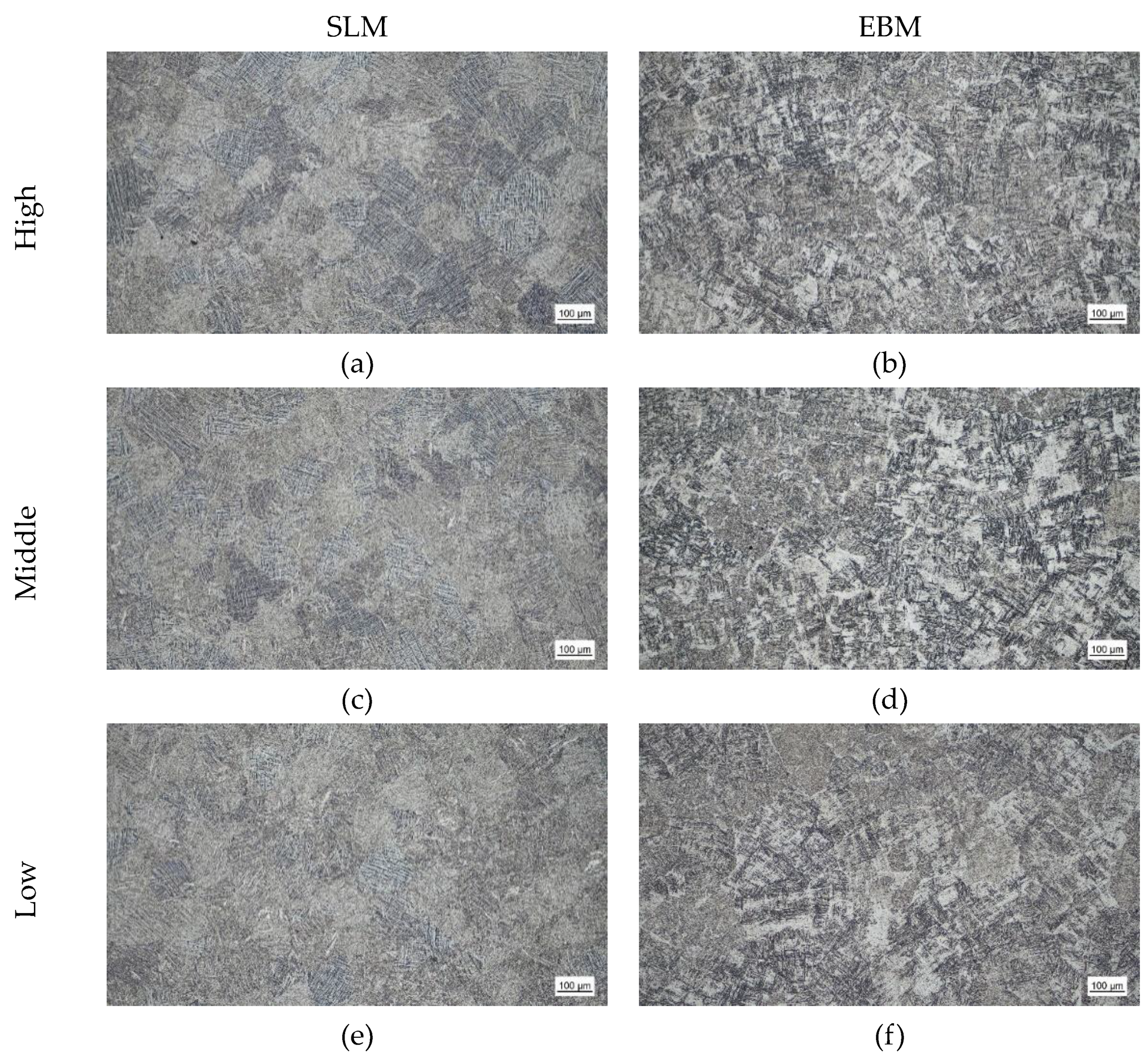
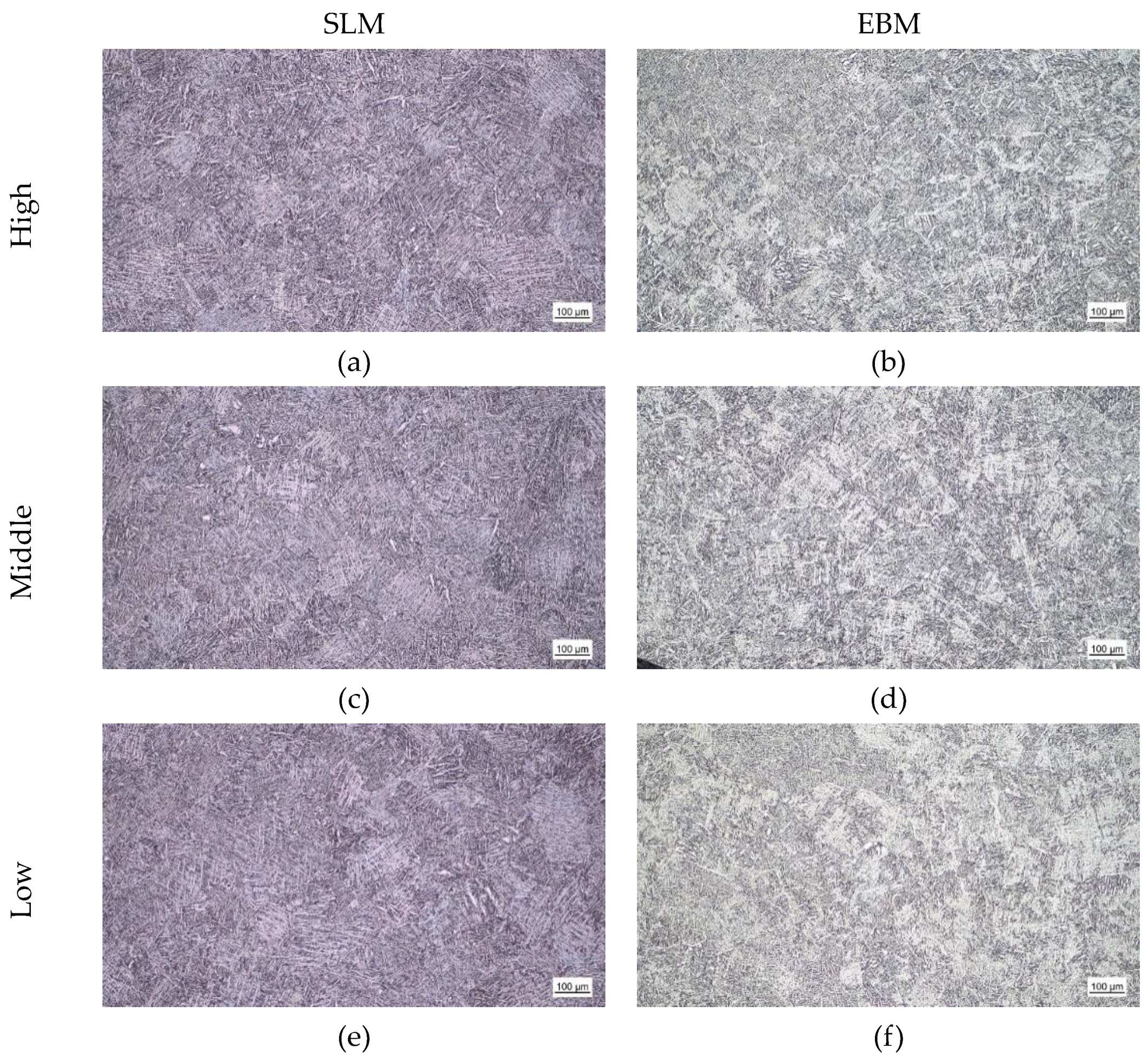
Both samples show an α acicular microstructure with the presence of β-phase in the α inter-laths. In the case of the SLM samples it is also possible to observe the prior β grains with a dimension of about 150 µm. The EBM samples show the same microstructure, but the prior β grain is not detected. The microstructure of the EBM seems to be less homogeneous compared to the SLM samples. The HIP treatment has the effect of producing a coarser microstructure for both analysed samples. No differences were found between the regions of the analysed samples.
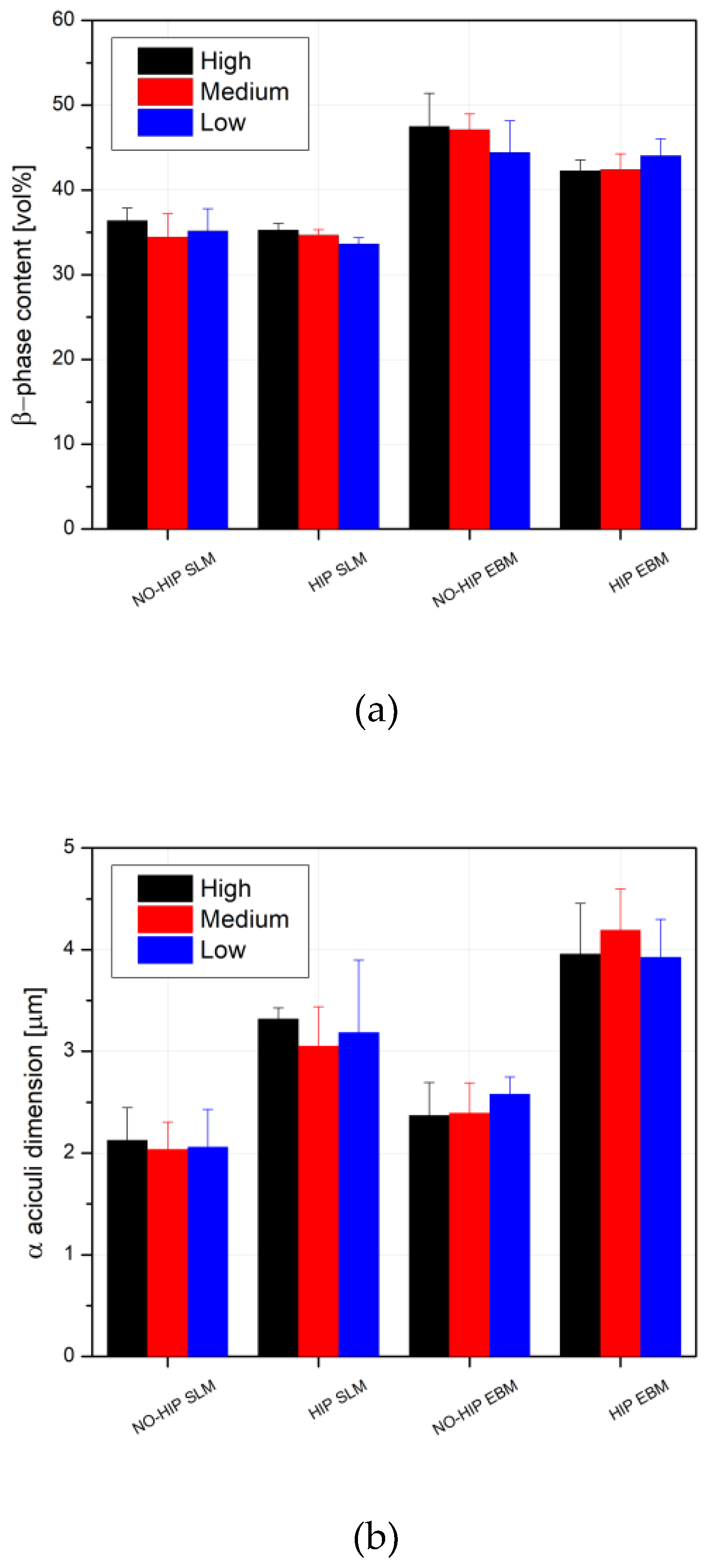
In order to better characterise the microstructure of the analysed samples, the α-phase dimension and the β-phase distribution were calculated using image analysis software, with procedure previously described. The results are summarised in
Figure 9. The β-phase content is lower in the SLM samples compared to the EBM ones. This is probably because the SLM samples start from a Ti martensite microstructure which decomposes into α- and β-phases after the heat treatment. The amounts are also lower since in SLM samples the β-phase also precipitates within the α-phase. In this case the phase is so small that the light microscope cannot resolve the dimension and it is probably underestimated by image analysis. It is also to consider certain amount of not transformed martensite that probably is present in the material [
19]. In general, the microstructural differences between the two batches in the as-printed condition are related to the different initial microstructure of the materials, which is decomposed martensite in the SLM samples and acicular α-phase with interactive β-phase in the EBM samples [
22]. In fact, this is usually related to a difference in the two microstructural parameters analysed in this work, which are usually lower in SLM.
However, in both cases, no difference was observed along the length of the sample in terms of β-phase content and the HIP process appears to have a negligible effect on it, at least in this experience. By analysing the α-phase dimension, it is possible to observe that this is homogenous along the length of the sample. As indicated above, the SLM samples have a finer microstructure compared to the EBM ones and again, as expected, the HIP process seems to slightly increase the grain size in both the cases. This is due to the fact that HIP takes place at high temperature under relatively high pressure, which can promote the formation of coarser phases [
15]. Also in the case of HIP, the starting microstructure has a strong effect on the material response in terms of β-phase content and α-phase dimension. In general, the SLM samples present lower β-phase content and finer grain size. This is because the SLM samples should at the beginning decompose the martensitic microstructure, while the EBM samples are only undergoing to coarsening of the initial microstructure due to the grain growth mechanism at high temperature.
3.2. Roughness Characterization
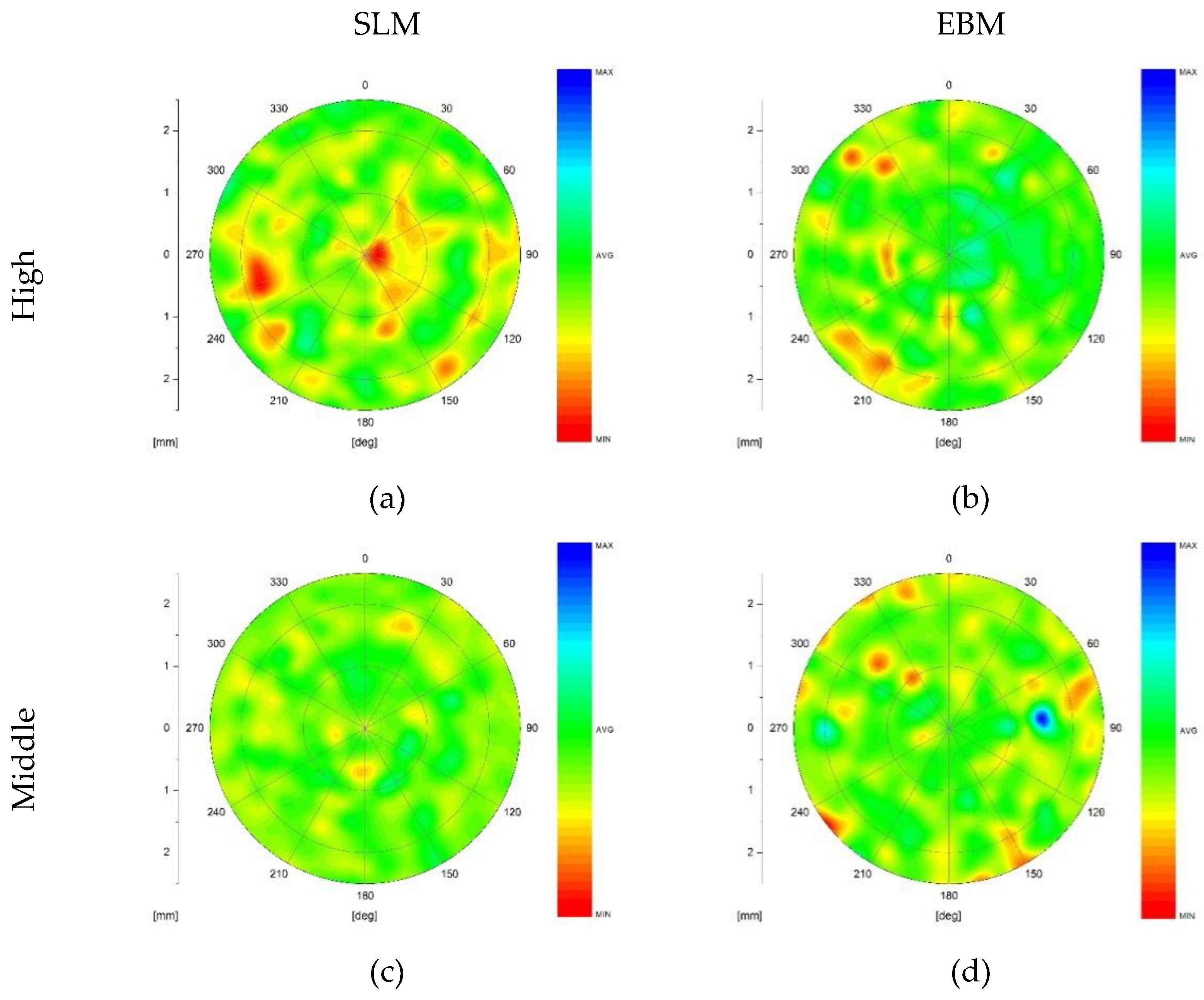
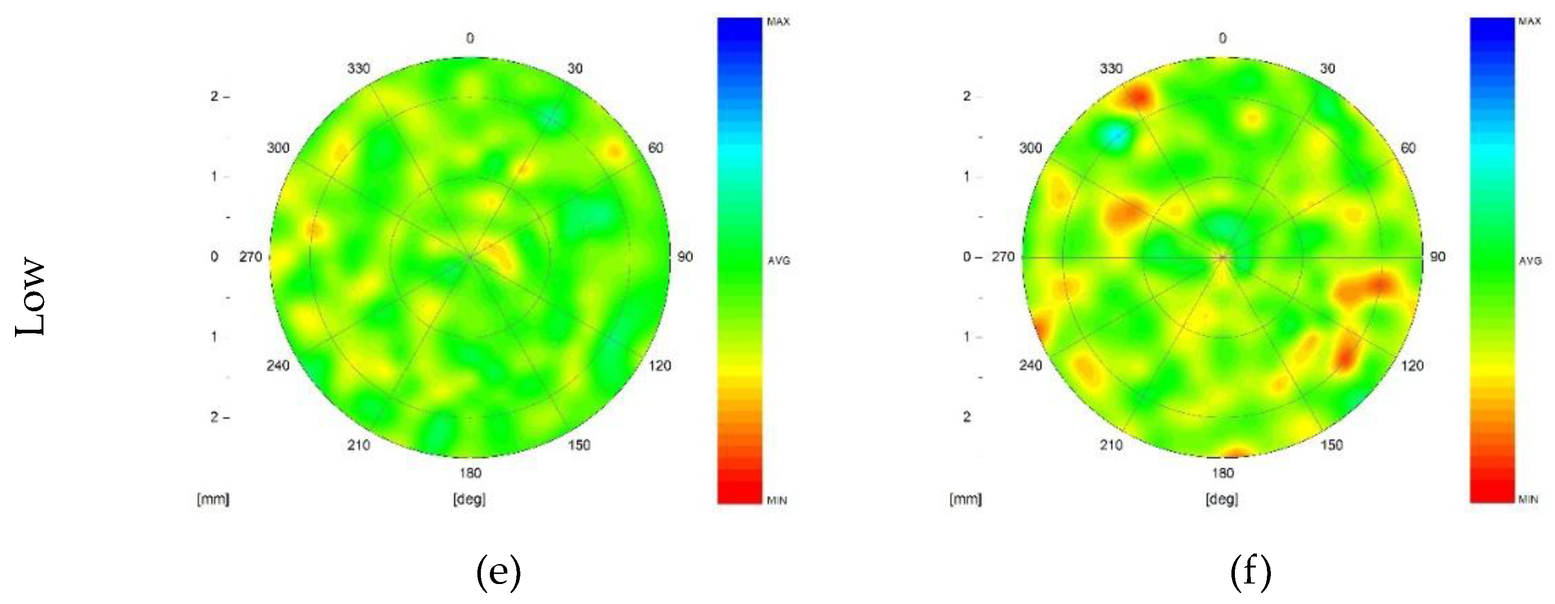
Another important parameter to consider in the evaluation of the fatigue properties of the material is the surface roughness. A detailed investigation, reported in
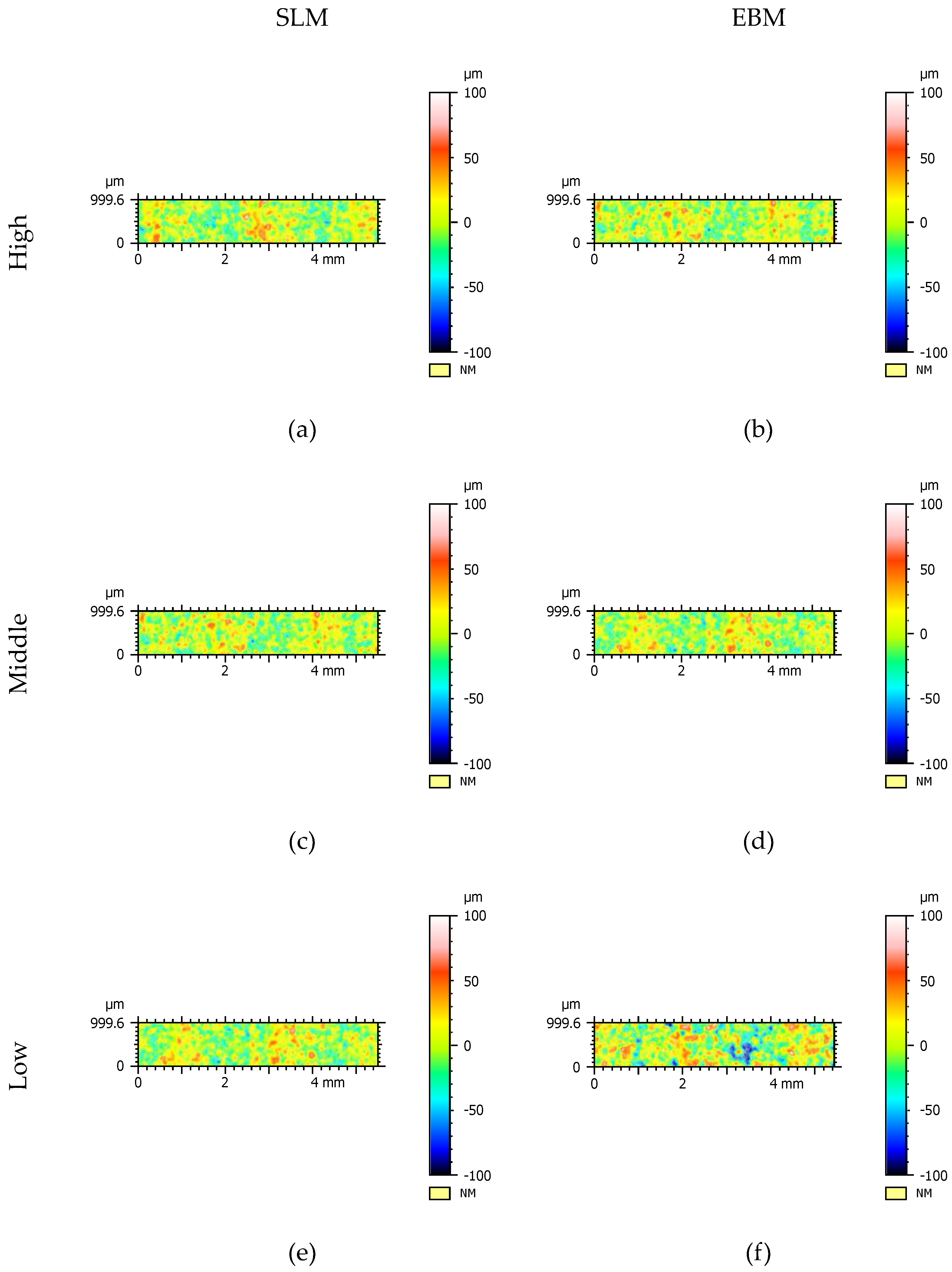
Figure 10, was done on the samples in the as-printed texture because most relevant to characterize the fatigue related crack initiation behaviour.
The surface texture of each sample analysed is homogeneous along the length of the gauge and present comparable surface characteristics in term of Ra, Rt and Rz in all regions analysed. The colormaps indicate the heights of different points in the surface, which in the present case are roughly distributed between -100 µm and +100 µm relative to the average surface. Specifically, the points that deviate negatively are represented with a range of colours from light green to deep blue. In contrast, points that are positively offset have a colour scale from yellow to deep red.
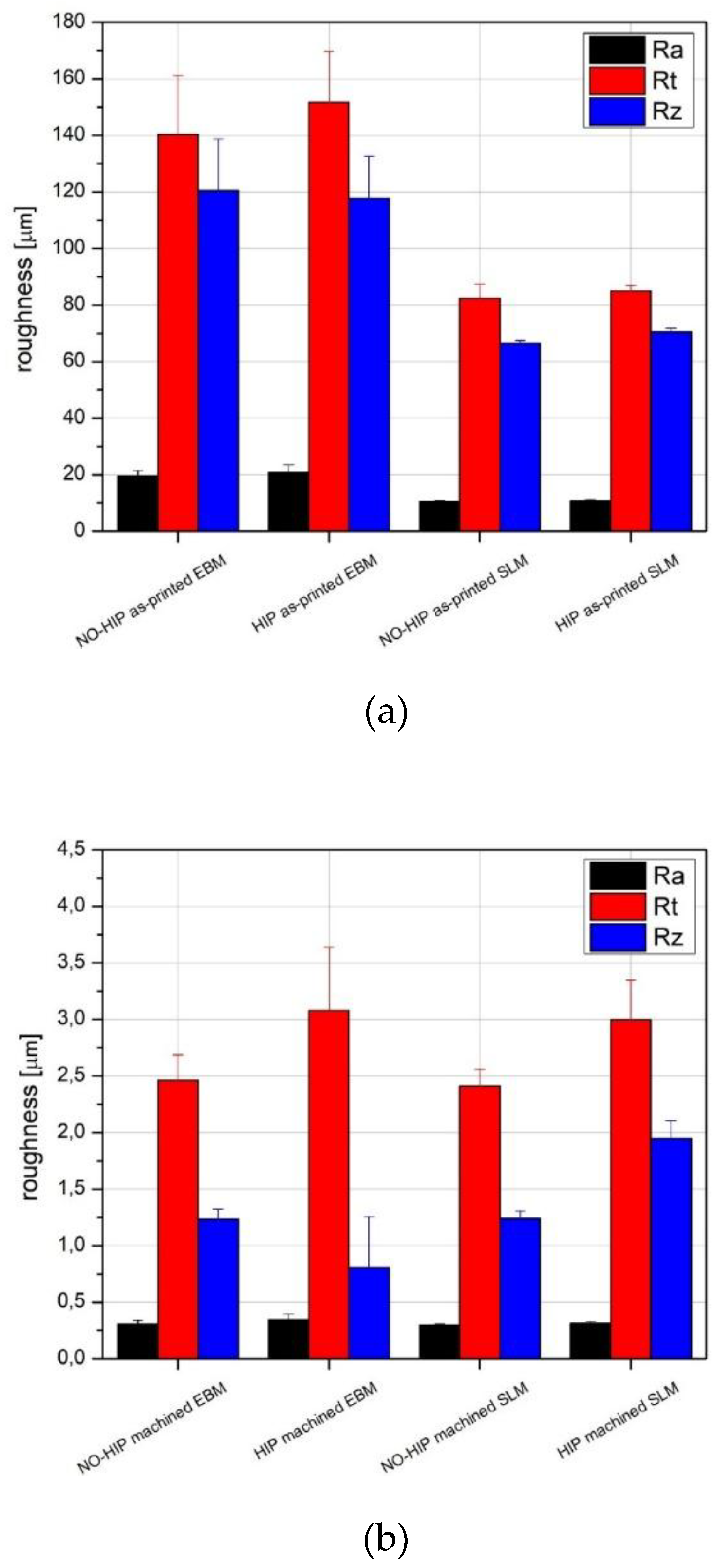
Some differences are observed between the SLM samples and the EBM samples, as shown in
Figure 11. In fact, as expected, the EBM samples are rougher, in agreement with several studies carried out on the surface texture of additively manufactured components [
55]. This difference is related to the printing conditions in terms of printing parameters (beam spot dimension) and powder size, which is typically coarser in the EBM process. The machining process removes all the as-printed surface by smoothing the surface of the sample. In addition, the HIP process does not seem to have an effect on surface morphology.
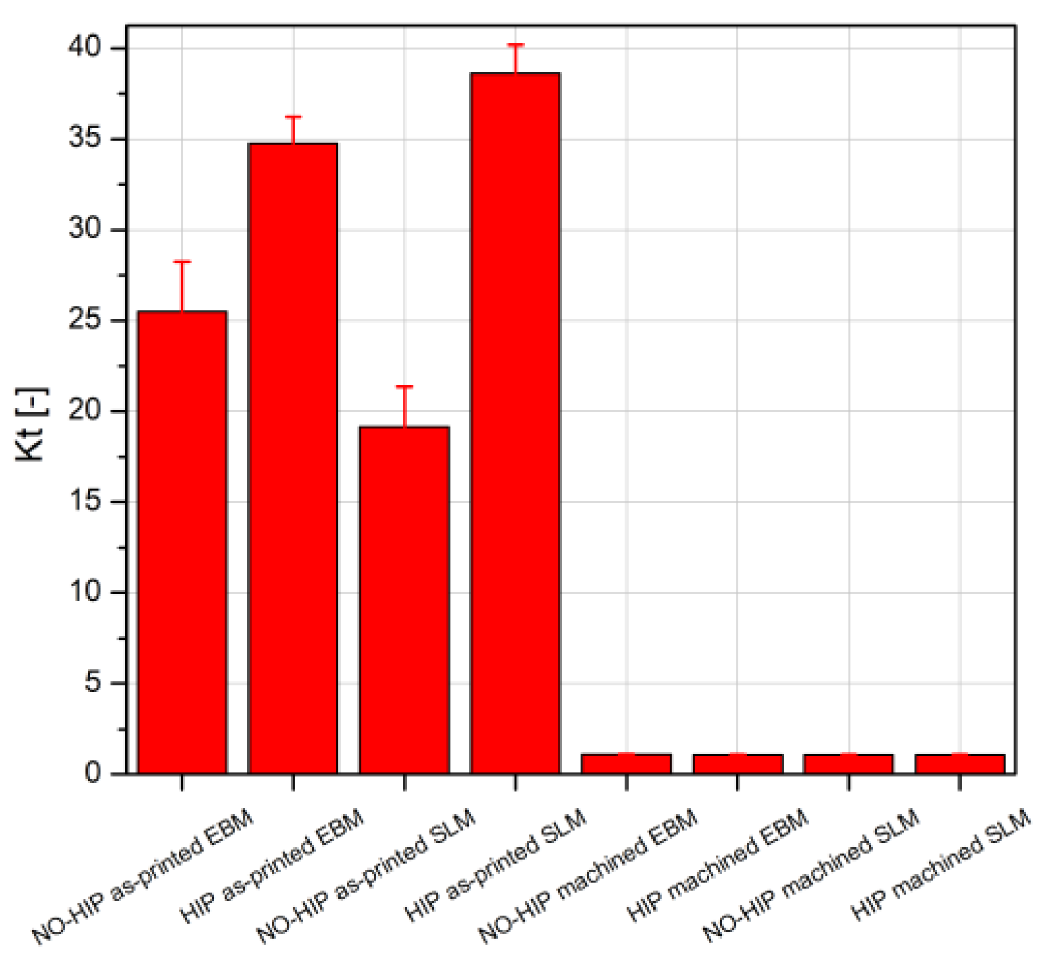
The surface intensity factor Kt is then calculated according to Arola Williams indications [
49] and shown in
Figure 12. It is possible to observe that the Kt of the as-printed surface is too large respect to the machined samples. This probably will have a great effect on fatigue properties of material, by decreasing the fatigue life. By analysing in detail the Kt values, it is possible to observe that the SLM present, in as-printed condition, a lower Kt respect to the EBM. The HIP process increases the surface Kt, probably because some un-melted particles will drop from the surface by increasing the Rt (see
Figure 11).
3.3. Microhardness Characterization
Another important parameter to consider in the evaluation of the fatigue properties of the material is the material microhardness.
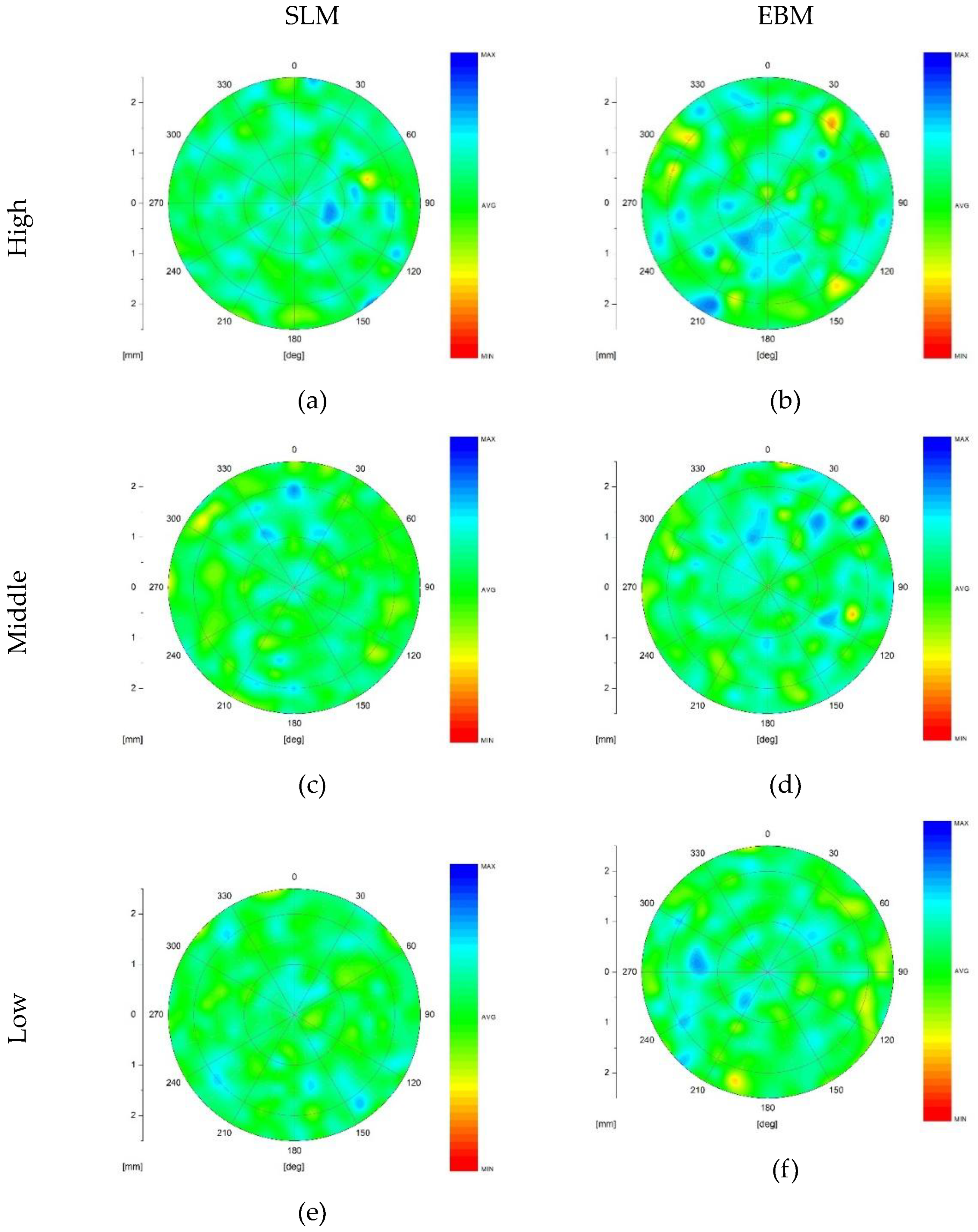
Figure 13 shows the microhardness maps obtained on the cross-sectional areas listed in
Figure 4 for the as-printed samples.
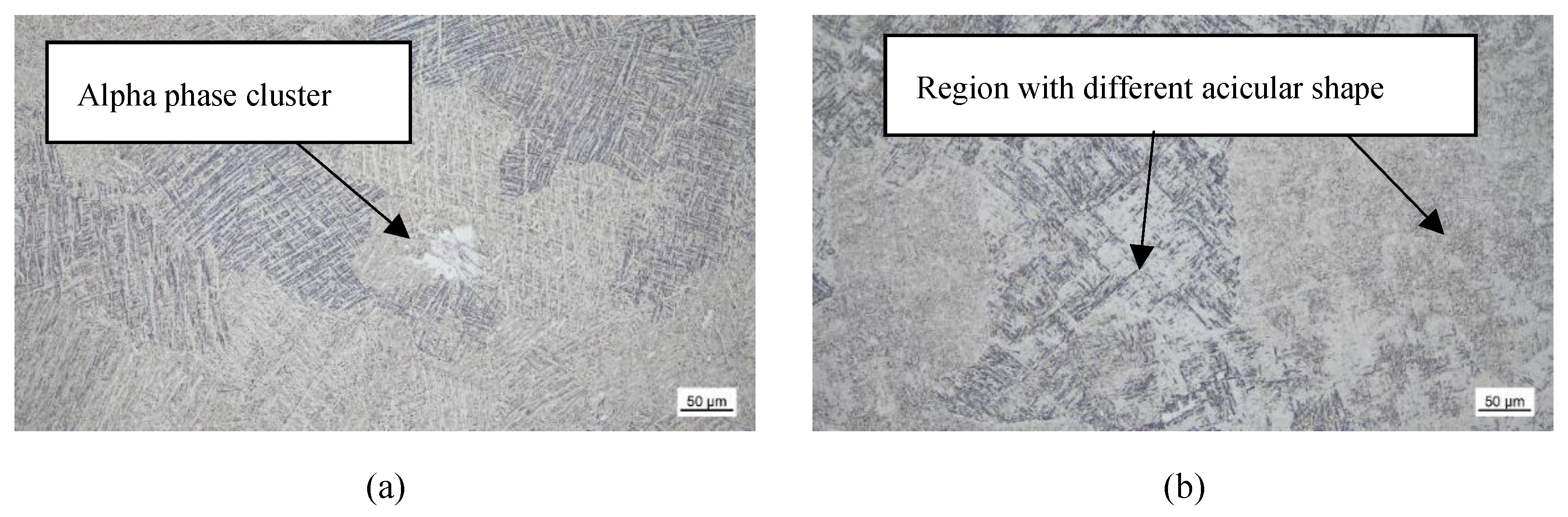
The hardness maps obtained on the cross sections of the as-printed samples show a slightly heterogeneous distribution of the mechanical properties. In fact, for both the SLM and EBM samples, some softer areas are detected, associated with regions where the microstructure is heterogeneous, such as regions enriched in α-phase or regions where the grains are slightly coarser (see the α grains in
Figure 14). The EBM sample presents the higher amount of these regions, which are homogeneously distributed in the three analysed positions. On the other hand, the SLM samples show a higher amount of these soft areas in the upper part with respect to the lower part. This is s probably due to its thermal history, which is modified during the printing process due to the gradual increase in temperature of the printed component [
27].
HIP has a beneficial effect on hardness homogeneity. In fact, the hardness maps do not show areas of lower hardness. In general, when comparing the results in
Figure 15, there is a gradual decrease in hardness associated with the effect of the heat treatment, which has reduced the heterogeneities by slightly coarsening the microstructure. A more homogenous hardness distribution is observed in the SLM samples. This probably is due to the fact that the starting microstructure (Ti martensite), before the HIP treatment, is more homogeneous in the SLM samples respect to the EBM samples, that presents its coarsened as-printed microstructure after HIP.
3.4. Tensile Tests
Table 4 shows the tensile tests results obtained on analysed specimens. The results are in agreement to ISO 5832-3:2021
Implants for surgery - Metallic materials - Part 3: Wrought titanium 6-aluminium 4-vanadium alloy [
44]. It is to highlight a slightly difference in mechanical properties between the HIP and NO-HIP samples, in particular for the Yeld Strength (YS) and Ultimate Tensile Strength (UTS). As observed, the EBM and SLM samples present the same properties in HIP conditions. In as-printed EBM samples and SLM heat treated samples some differences were detected. In particular the SLM samples present slightly lower mechanical properties respect to the EBM samples, this probably is related to the slightly different microstructure of materials.
3.5. Fatigue Tests
Uniaxial fatigue tests were carried out on all the batches analysed in the experimental procedure. The main objective was to determine the effect of both heat treatment and surface finishing on the fatigue resistance of the material for samples produced by EBM and SLM techniques.
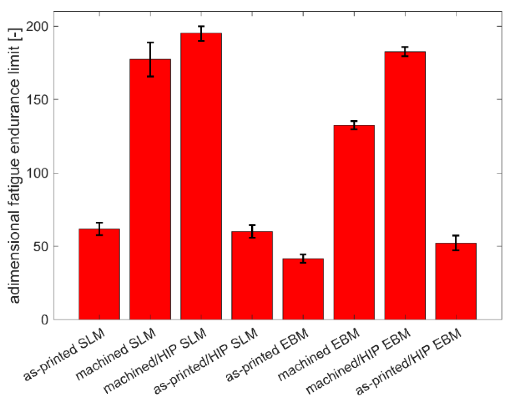
By analysing the graph shown in
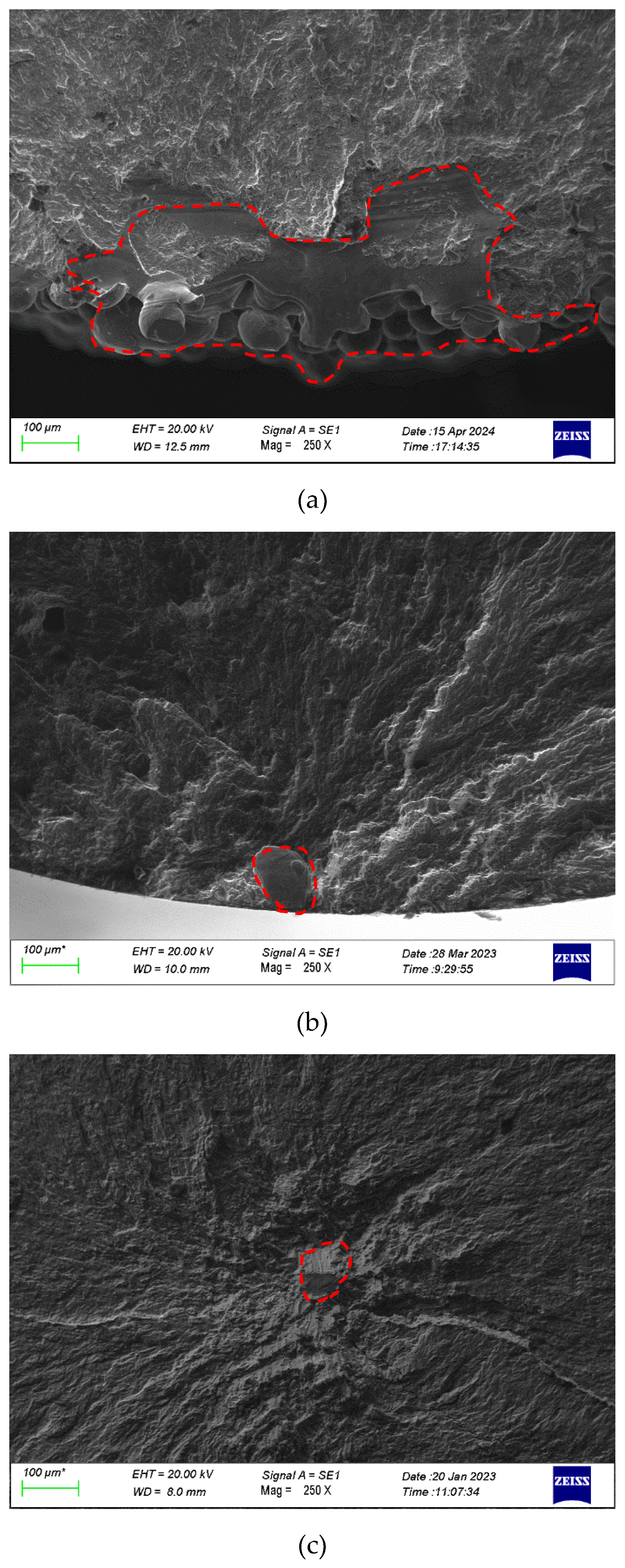
Figure 16, it is possible to observe that the as-printed samples present a lower fatigue behaviour, as expected. In fact, it can be observed that the failure occurs at low applied loads. Comparing the two printing techniques analysed in this test campaign, it is possible to observe that the EBM as-printed samples present the worst fatigue resistance and this agrees with the surface characterisation of the samples, which showed a higher roughness with respect to the SLM ones. In this case, it appears that the fatigue behaviour is controlled more by the surface condition than by the internal defects or microstructure, as suggested by the fracture surface analysis which showed typical crack nucleation in the proximity of the surface asperities (
Figure 17(a)). When the asperity is removed, the fatigue resistance increases abruptly, still in favour of the SLM samples. This demonstrates how the surface asperities are more critical than the internal defects which are the predominant cause of failure when the as-printed surface is removed (
Figure 17(b)). Indeed, this statement is also confirmed by the fatigue behaviour of the EBM samples, which is lower than the SLM ones, and this is in agreement with the internal defect characterisation, which showed a higher amount of coarse defects in the EBM samples.
On the other hand, the HIP treatment increases the fatigue resistance of the machined samples for both EBM and SLM techniques, and also in this case the SLM presents even better fatigue resistance. The failures usually occur at a number of cycles very close to the run-out and the crack nucleation is usually observed close to the microstructural heterogeneities rather than to the internal defects or to the surface condition (
Figure 17(c)). The HIP process on as-printed surface is not effective to improve the fatigue properties of material due to the fact that the surface asperities are controlling the fatigue crack nucleation.
Looking at the fatigue limit calculated by the Dixon-Mood approach, a strong agreement with the S-N curve discussion can be observed. In particular, the SLM samples show a better fatigue performance in each condition analysed with respect to the EBM samples. This behaviour is in agreement with the previous discussion: the SLM sample in as-printed condition presents a smoother surface, the SLM one in machined condition presents finer and lower amount of internal defects. The HIP treatment, in the case of as-printed surfaces, is not effective to increase the fatigue properties of material that present the same behaviour of the NO-HIP condition. The same consideration concerning the difference between SLM and EBM on fatigue life is still valid for machined and HIP condition even if the difference in this case seems negligible between the technologies due to the similar microstructure obtained on both EBM and SLM samples after HIP treatment. It is also to highlight that the fracture surface of the HIP samples, in most of the analysed ones, presents a crack nucleation site that does not correspond to an internal defect but rather to a microstructural discontinuity that can be correlated to possible areas where the pore was present and, after HIP, closed with a dynamic recrystallization. In particular, some authors have observed that the microstructure is equiaxed and biphasic [
56].
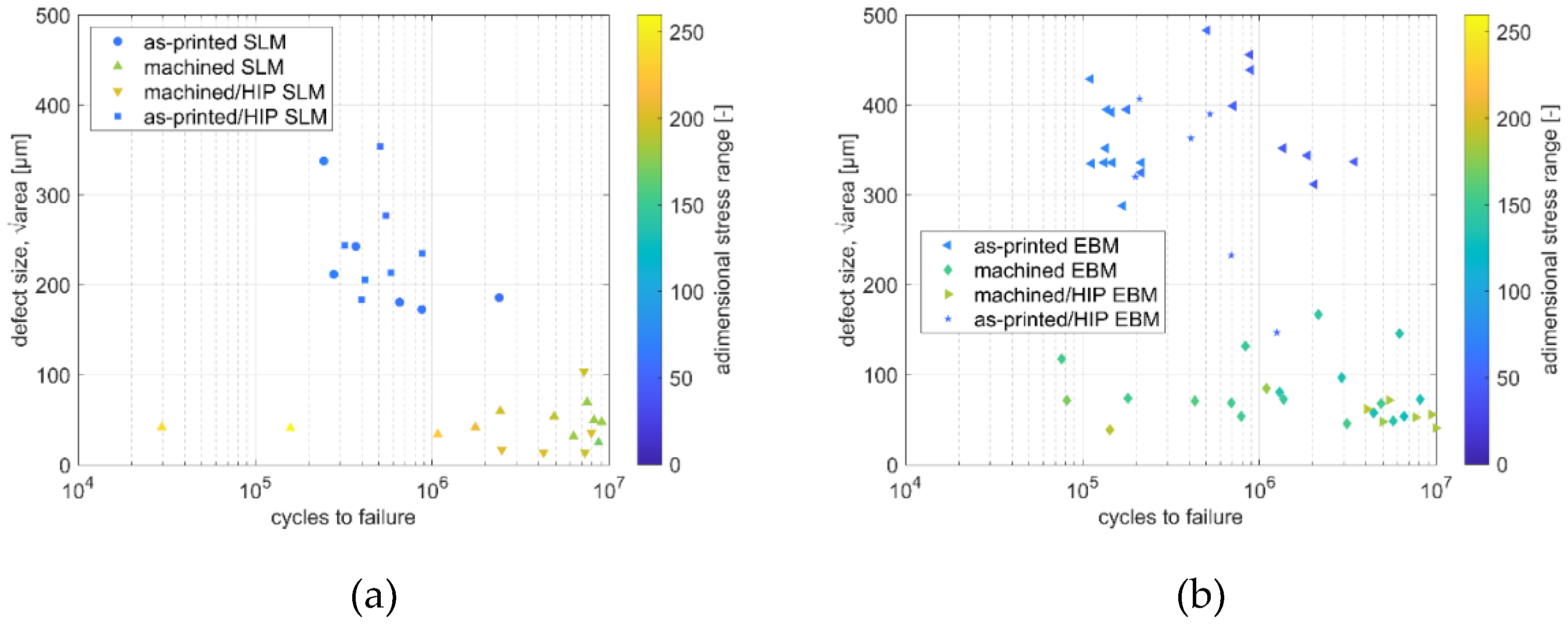
In order to better characterise the failures occurring at the critical defect from which the crack nucleated,
Figure 18 shows a graph summarising, for failed samples, the number of cycles as a function of the dimensionless applied load and the defect extension. As previously mentioned, the as-printed samples exhibit larger internal defects compared to other conditions. Among the two printing techniques, EBM samples show the coarsest defects, a trend also observed in the machined condition. These larger defects in EBM are reflected in the bigger crack nucleation sites found in failed samples. On the other hand, the HIP samples present smaller defects that caused the samples to fail, which usually occurs with low data scatter and failures closer to the fatigue limit. In addition, it is possible to observe that the effect of the dimensionless applied load is to anticipate the failure of the samples when it is increased. It is also evidenced that the applied load becomes less invasive on cycles to failure when the dimension of crack nucleation site is becoming finer. This probably is related to the severity of the crack nucleation discontinuity that in HIP samples is usually finer and in round shape respect to the other tested conditions. Again, the SLM samples show the smallest extension of the crack nucleation area. By analysing in detail the graphs, it is possible to observe that each tested condition presents a dimension class of the defects responsible of the crack nucleation. These defects are coarser for the EBM samples due to the fact that the surface texture is of lower quality compared to the SLM ones. In addition, the dispersion of the data is higher for the EBM samples. In this case, the defects are usually gas pores or lack of fusion and correspond to the internal defects detected in
Figure 6 [
17]. In fact, the EBM again present the higher data dispersion due to the wider dimensional distribution of the defects observed during the characterisation of the internal voids. As expected, the HIP samples show a critical flaw discontinuity dimensional class below 50 µm. This again corresponds to the dimensional distribution of the internal defects. Moreover, the EBM samples have the coarser defects. It can be seen that a reduction in the size of crack nucleation defects means a failure closer to the fatigue limit of the material.
By analysing the effect of defect size as a function of applied load, it can be observed for machined samples that failure occurs at a lower number of cycles when the applied load is higher. This is probably related to the fact that increasing the applied load means anticipating the activation of the flaw and thus the failure of the material. This is also true for the as-printed samples, but in this case the initial defect extension is widely dispersed and is the main cause of crack nucleation. In machined samples subjected to HIP, the internal defects are probably local microstructural changes, as previously demonstrated, whose dimensions are within a very narrow dispersion range. On the other hand, the defects that produced the crack nucleation in HIP as-printed samples present similar dimension respect to the NO-HIP samples with as-printed surface. This confirms that HIP treatment has little effect on as-printed surfaces, as surface asperities dominate the material's fatigue behaviour.
4. Conclusions
The present work aims to highlight the state of the art in terms of fatigue studies concerning the fatigue properties of the Ti6Al4V alloy produced by last released industrial SLM and EBM processes. Particular attention has been paid to the surface finish and the thermal treatments used as a post-processing for the additive manufactured products.
The main results obtained from this work are:
the internal defects, limited by a correct choice of printing parameters, are usually coarser for the EBM samples respect to the SLM ones. HIP greatly reduced the content and dimension of these defects;
the microstructure of the samples is similar, although the EBM samples usually show coarser metallurgical features and a slightly higher beta phase content. This is also observed in the HIP samples. The causes are related to the initial microstructure prior to heat treatment (no heat treatment for EBM samples) or the HIP process. This is also reflected in the microhardness distribution, although the HIP process made the microstructure more homogeneous;
the surface texture in the as-printed condition is strongly influenced by the printing technique and also by the process parameters. The fatigue resistance of the samples is strongly influenced by the surface condition and texture, which is also the origin of the fatigue failures. In this case, the EBM samples exhibited the worst fatigue behaviour in the as-printed condition. When the as-printed texture is removed, the fatigue life is strongly influenced by internal defects. The HIP treatment of rough surfaces, as the as-printed ones, is not effective on increase the fatigue life of material. The difference in fatigue resistance between EBM and SLM is strongly reduced for machined and HIP samples;
the applied load plays a role in fatigue crack nucleation. In particular, for the same defect size, the defect induces an anticipated failure at higher applied loads.
Author Contributions
F. Sordetti: formal analysis, investigation, writing—original draft preparation, writing—review and editing. N. Picco: formal analysis, investigation, writing—review and editing. M. Pelegatti: formal analysis, investigation, writing—review and editing. R. Toninato: supervision, writing—review and editing. M. Petruzzi: formal analysis, investigation, writing—review and editing. F. Milan: writing—review and editing. E. Avoledo: writing—review and editing. A. Tognan: writing—review and editing. E. Marin: writing—review and editing. L. Fedrizzi: writing—review and editing. M. Magnan: investigation, formal analysis. E. Salvati: conceptualization, writing—review and editing. M. Pressacco: funding acquisition, writing—review and editing. A. Lanzutti: project administration, conceptualization, supervision, writing—original draft preparation. All authors have read and agreed to the published version of the manuscript.
Funding
This research was funded by POR FESR 2021–2027 - Ricerca e sviluppo - Bando2022 - Progetto EFESTO Prat. N. 2022/76’’ granted by Regione FVG Friuli Venezia Giulia to LimaCorporate S.p.A.
Data Availability Statement
The raw/processed data required to reproduce these findings cannot be shared at this time as the data also forms part of an ongoing study.
Acknowledgments
Elia Marin received support from L-INSIGHT program (program for the development of the next generation leading researchers with global insights), Kyoto University, and a research grant from Nippon sheet glass foundation for material science and engineering.
Conflicts of Interest
The authors declare no conflicts of interest. The funders had no role in the design of the study; in the collection, analyses, or interpretation of data; in the writing of the manuscript; or in the decision to publish the results.
Abbreviations
The following abbreviations are used in this manuscript:
| HIP |
Hot Isostatic Pressing |
| VHT |
Vacuum Heat Treatment |
| SLM |
Selective Laser Melting |
| EBM |
Electron Beam Melting |
References
- Pasang T, Budiman AS, Wang JC, Jiang CP, Boyer R, Williams J, et al. Additive manufacturing of titanium alloys – Enabling re-manufacturing of aerospace and biomedical components. Microelectron Eng 2023;270. [CrossRef]
- Blakey-Milner B, Gradl P, Snedden G, Brooks M, Pitot J, Lopez E, et al. Metal additive manufacturing in aerospace: A review. Mater Des 2021;209. [CrossRef]
- Madhavadas V, Srivastava D, Chadha U, Aravind Raj S, Sultan MTH, Shahar FS, et al. A review on metal additive manufacturing for intricately shaped aerospace components. CIRP J Manuf Sci Technol 2022;39:18–36. [CrossRef]
- Marin E, Lanzutti A. Biomedical Applications of Titanium Alloys: A Comprehensive Review. Materials 2024;17. [CrossRef]
- Marin E, Lanzutti A. History of Metallic Orthopedic Materials. Metals (Basel) 2025;15:378. [CrossRef]
- Zhang LC, Chen LY. A Review on Biomedical Titanium Alloys: Recent Progress and Prospect. Adv Eng Mater 2019;21. [CrossRef]
- Campanelli LC. A review on the recent advances concerning the fatigue performance of titanium alloys for orthopedic applications. J Mater Res 2021;36:151–65. [CrossRef]
- Molaei R, Fatemi A, Sanaei N, Pegues J, Shamsaei N, Shao S, et al. Fatigue of additive manufactured Ti-6Al-4V, Part II: The relationship between microstructure, material cyclic properties, and component performance. Int J Fatigue 2020;132. [CrossRef]
- Denti L, Bassoli E, Gatto A, Santecchia E, Mengucci P. Fatigue life and microstructure of additive manufactured Ti6Al4V after different finishing processes. Materials Science and Engineering: A 2019;755:1–9. [CrossRef]
- Wu GQ, Shi CL, Sha W, Sha AX, Jiang HR. Effect of microstructure on the fatigue properties of Ti-6Al-4V titanium alloys. Mater Des 2013;46:668–74. [CrossRef]
- Nguyen HD, Pramanik A, Basak AK, Dong Y, Prakash C, Debnath S, et al. A critical review on additive manufacturing of Ti-6Al-4V alloy: Microstructure and mechanical properties. Journal of Materials Research and Technology 2022;18:4641–61. [CrossRef]
- Masuo H, Tanaka Y, Morokoshi S, Yagura H, Uchida T, Yamamoto Y, et al. Influence of defects, surface roughness and HIP on the fatigue strength of Ti-6Al-4V manufactured by additive manufacturing. Int J Fatigue 2018;117:163–79. [CrossRef]
- Jiao Z, Wu X, Yu H, Xu R, Wu L. High cycle fatigue behavior of a selective laser melted Ti6Al4V alloy: Anisotropy, defects effect and life prediction. Int J Fatigue 2023;167. [CrossRef]
- Naab B, Ramachandran S, Mirihanage W, Celikin M. Fatigue prediction through quantification of critical defects and crack growth behaviour in additively manufactured Ti-6Al-4V alloy. Materials Science and Engineering: A 2024;903. [CrossRef]
- Hrabe N, Gnäupel-Herold T, Quinn T. Fatigue properties of a titanium alloy (Ti–6Al–4V) fabricated via electron beam melting (EBM): Effects of internal defects and residual stress. Int J Fatigue 2017;94:202–10. [CrossRef]
- Nicoletto G. Anisotropic high cycle fatigue behavior of Ti–6Al–4V obtained by powder bed laser fusion. Int J Fatigue 2017;94:255–62. [CrossRef]
- Chern AH, Nandwana P, Yuan T, Kirka MM, Dehoff RR, Liaw PK, et al. A review on the fatigue behavior of Ti-6Al-4V fabricated by electron beam melting additive manufacturing. Int J Fatigue 2019;119:173–84. [CrossRef]
- Hrabe NW, Heinl P, Flinn B, Körner C, Bordia RK. Compression-compression fatigue of selective electron beam melted cellular titanium (Ti-6Al-4V). J Biomed Mater Res B Appl Biomater 2011;99 B:313–20. [CrossRef]
- Tusher MMH, Ince A. Effect of stress-relieved heat treatment on very high cycle fatigue performance of additive manufactured Ti-6Al-4V alloy. Fatigue Fract Eng Mater Struct 2023;46:3982–4000. [CrossRef]
- Pessard E, Lavialle M, Laheurte P, Didier P, Brochu M. High-cycle fatigue behavior of a laser powder bed fusion additive manufactured Ti-6Al-4V titanium: Effect of pores and tested volume size. Int J Fatigue 2021;149. [CrossRef]
- Fatemi A, Molaei R, Simsiriwong J, Sanaei N, Pegues J, Torries B, et al. Fatigue behaviour of additive manufactured materials: An overview of some recent experimental studies on Ti-6Al-4V considering various processing and loading direction effects. Fatigue Fract Eng Mater Struct 2019;42:991–1009. [CrossRef]
- Pegues JW, Shao S, Shamsaei N, Sanaei N, Fatemi A, Warner DH, et al. Fatigue of additive manufactured Ti-6Al-4V, Part I: The effects of powder feedstock, manufacturing, and post-process conditions on the resulting microstructure and defects. Int J Fatigue 2020;132. [CrossRef]
- Cutolo A, Elangeswaran C, Muralidharan GK, Van Hooreweder B. On the role of building orientation and surface post-processes on the fatigue life of Ti-6Al-4V coupons manufactured by laser powder bed fusion. Materials Science and Engineering: A 2022;840. [CrossRef]
- Fu R, Zheng L, Zhong Z, Hong Y. High-cycle and very-high-cycle fatigue behavior at two stress ratios of Ti-6Al-4V manufactured via laser powder bed fusion with different surface states. Fatigue Fract Eng Mater Struct 2023;46:2348–63. [CrossRef]
- Shamir M, Syed AK, Janik V, Biswal R, Zhang X. The role of microstructure and local crystallographic orientation near porosity defects on the high cycle fatigue life of an additive manufactured Ti-6Al-4V. Mater Charact 2020;169. [CrossRef]
- Batalha GF, Silva LC, Coelho RS, Teixeira MCC, Castro TL, Pereira MVS, et al. Mechanical properties characterization of Ti-6Al-4 V grade 5 (recycled) additively manufactured by selective electron beam melting (EB-PBF). Eng Fail Anal 2024;157. [CrossRef]
- Takase A, Ishimoto T, Morita N, Ikeo N, Nakano T. Comparison of phase characteristics and residual stresses in ti-6al-4v alloy manufactured by laser powder bed fusion (L-pbf) and electron beam powder bed fusion (eb-pbf) techniques. Crystals (Basel) 2021;11. [CrossRef]
- Chastand V, Quaegebeur P, Maia W, Charkaluk E. Comparative study of fatigue properties of Ti-6Al-4V specimens built by electron beam melting (EBM) and selective laser melting (SLM). Mater Charact 2018;143:76–81. [CrossRef]
- Afroz L, Das R, Qian M, Easton M, Brandt M. Fatigue behaviour of laser powder bed fusion (L-PBF) Ti–6Al–4V, Al–Si–Mg and stainless steels: a brief overview. Int J Fract 2022;235:3–46. [CrossRef]
- Gao X, Tao C, Wu S. Anisotropic high cycle fatigue property estimation for laser additive manufactured Ti6Al4V alloy dependence on tomographic imaging of defect population. Journal of Materials Research and Technology 2023;22:1971–82. [CrossRef]
- Lanzutti A, Magnan M, Vaglio E, Totis G, Sortino M, Fedrizzi L. Study of the Effect of L-PBF Technique Temporal Evolution on Microstructure, Surface Texture, and Fatigue Performance of Ti gr. 23 Alloy. Metals (Basel) 2023;13. [CrossRef]
- Salvati E, Tognan A, Laurenti L, Pelegatti M, De Bona F. A defect-based physics-informed machine learning framework for fatigue finite life prediction in additive manufacturing. Mater Des 2022;222:111089. [CrossRef]
- Avoledo E, Petruzzi M, Pelegatti M, Tognan A, De Bona F, Pressacco M, et al. Defect Analysis by Computed Tomography in Metallic Materials: Optimisation, Uncertainty Quantification and Classification. n.d.
- Naab B, Celikin M. The role of microstructural evolution on the fatigue behavior of additively manufactured Ti–6Al–4V alloy. Materials Science and Engineering: A 2022;859. [CrossRef]
- Ariza DA, Arrieta E, Banuelos C, Colón BJ, Murr LE, Wicker RB, et al. Comparison of fatigue life behavior between 4-point and uniaxial loading for L-PBF Ti–6Al–4V after HIP treatments. Results in Materials 2024;22. [CrossRef]
- Jimenez EH, Kreitcberg A, Moquin E, Brailovski V. Influence of Post-Processing Conditions on the Microstructure, Static, and Fatigue Resistance of Laser Powder Bed Fused Ti-6Al-4V Components. Journal of Manufacturing and Materials Processing 2022;6. [CrossRef]
- Saville AI, Benzing JT, Semiatin SL, Derimow N, Hrabe NW. Defect recrystallization in subtransus hot isostatic pressing of electron beam powder bed fusion Ti-6Al-4V. Addit Manuf 2024;91. [CrossRef]
- Jin B, Wang Q, Zhao L, Pan A, Ding X, Gao W, et al. A Review of Additive Manufacturing Techniques and Post-Processing for High-Temperature Titanium Alloys. Metals (Basel) 2023;13. [CrossRef]
- Shiyas KA, Ramanujam R. A review on post processing techniques of additively manufactured metal parts for improving the material properties. Mater Today Proc, vol. 46, Elsevier Ltd; 2021, p. 1429–36. [CrossRef]
- Ali M, Almotari A, Algamal A, Qattawi A. Recent Advancements in Post Processing of Additively Manufactured Metals Using Laser Polishing. Journal of Manufacturing and Materials Processing 2023;7. [CrossRef]
- Standard Practice for Conducting Force Controlled Constant Amplitude Axial Fatigue Tests of Metallic Materials 1. n.d.
- Takase A, Ishimoto T, Morita N, Ikeo N, Nakano T. Comparison of phase characteristics and residual stresses in ti-6al-4v alloy manufactured by laser powder bed fusion (L-pbf) and electron beam powder bed fusion (eb-pbf) techniques. Crystals (Basel) 2021;11. [CrossRef]
- Tusher MMH, Ince A. Effect of stress-relieved heat treatment on very high cycle fatigue performance of additive manufactured Ti-6Al-4V alloy. Fatigue Fract Eng Mater Struct 2023;46:3982–4000. [CrossRef]
- ISO 5832-3. Surgical implants - Metallic materials - Part 3: Titanium 6-aluminium 4-vanadium alloy 2021.
- ASTM International. ASTM F3001-14(2021): Standard Specification for Additive Manufacturing Titanium-6 Aluminum-4 Vanadium ELI (Extra Low Interstitial) with Powder Bed Fusion 2021.
- Chern AH, Nandwana P, Yuan T, Kirka MM, Dehoff RR, Liaw PK, et al. A review on the fatigue behavior of Ti-6Al-4V fabricated by electron beam melting additive manufacturing. Int J Fatigue 2019;119:173–84. [CrossRef]
- Chastand V, Quaegebeur P, Maia W, Charkaluk E. Comparative study of fatigue properties of Ti-6Al-4V specimens built by electron beam melting (EBM) and selective laser melting (SLM). Mater Charact 2018;143:76–81. [CrossRef]
- ISO. ISO 21920-3 2021 Geometrical product specifications (GPS) — Surface texture: Profile - Part 3: Specification operators 2021.
- Arola D, Williams CL. Estimating the fatigue stress concentration factor of machined surfaces. vol. 24. 2002.
- Lanzutti A, Pujatti M, Magnan M, Andreatta F, Nurmi H, Silvonen A, et al. Uniaxial fatigue properties of closed die hot forged 42CrMo4 steel: Effect of flash and mechanical surface treatments. Mater Des 2017;132:324–36. [CrossRef]
- Qian G, Li Y, Paolino DS, Tridello A, Berto F, Hong Y. Very-high-cycle fatigue behavior of Ti-6Al-4V manufactured by selective laser melting: Effect of build orientation. Int J Fatigue 2020;136:105628. [CrossRef]
- Masuo H, Tanaka Y, Morokoshi S, Yagura H, Uchida T, Yamamoto Y, et al. Influence of defects, surface roughness and HIP on the fatigue strength of Ti-6Al-4V manufactured by additive manufacturing. Int J Fatigue 2018;117:163–79. [CrossRef]
- Dixon WJ, Mood AM. A Method for Obtaining and Analyzing Sensitivity Data. J Am Stat Assoc 1948;43:109. [CrossRef]
- Tammas-Williams S, Withers PJ, Todd I, Prangnell PB. The Effectiveness of Hot Isostatic Pressing for Closing Porosity in Titanium Parts Manufactured by Selective Electron Beam Melting. Metall Mater Trans A Phys Metall Mater Sci 2016;47:1939–46. [CrossRef]
- Chan KS, Koike M, Mason RL, Okabe T. Fatigue life of titanium alloys fabricated by additive layer manufacturing techniques for dental implants. Metall Mater Trans A Phys Metall Mater Sci 2013;44:1010–22. [CrossRef]
- Saville AI, Benzing JT, Semiatin SL, Derimow N, Hrabe NW. Defect recrystallization in subtransus hot isostatic pressing of electron beam powder bed fusion Ti-6Al-4V. Addit Manuf 2024;91:104349. [CrossRef]
Figure 1.
Sample geometry adopted for the fatigue tests.
Figure 1.
Sample geometry adopted for the fatigue tests.
Figure 2.
Different surface finishing of the analysed samples: (a) as-printed surface, (b) machined surface.
Figure 2.
Different surface finishing of the analysed samples: (a) as-printed surface, (b) machined surface.
Figure 3.
Top and lateral view of the build design used for the production of the EBM batches.
Figure 3.
Top and lateral view of the build design used for the production of the EBM batches.
Figure 4.
Scheme of the sample extraction map for both microstructural and mechanical characterization.
Figure 4.
Scheme of the sample extraction map for both microstructural and mechanical characterization.
Figure 5.
Porosity characterisation results: (a) volumetric content, (b) dimensional distribution.
Figure 5.
Porosity characterisation results: (a) volumetric content, (b) dimensional distribution.
Figure 6.
Representative images of the internal voids detected by image analysis. In red are highlighted the voids: (a) NO-HIP SLM, (b) NO-HIP EBM, (c) HIP SLM, (d) HIP EBM.
Figure 6.
Representative images of the internal voids detected by image analysis. In red are highlighted the voids: (a) NO-HIP SLM, (b) NO-HIP EBM, (c) HIP SLM, (d) HIP EBM.
Figure 7.
Microstructure of samples in the NO-HIP condition: (a) SLM high, (b) EBM high, (c) SLM middle, (d) EBM middle, (e) SLM low, (f) EBM low.
Figure 7.
Microstructure of samples in the NO-HIP condition: (a) SLM high, (b) EBM high, (c) SLM middle, (d) EBM middle, (e) SLM low, (f) EBM low.
Figure 8.
Microstructure of samples in the HIP condition: (a) SLM high, (b) EBM high, (c) SLM middle, (d) EBM middle, (e) SLM low, (f) EBM low.
Figure 8.
Microstructure of samples in the HIP condition: (a) SLM high, (b) EBM high, (c) SLM middle, (d) EBM middle, (e) SLM low, (f) EBM low.
Figure 9.
(a) β-phase content, (b) α aciculi dimension of the samples with different thermal condition.
Figure 9.
(a) β-phase content, (b) α aciculi dimension of the samples with different thermal condition.
Figure 10.
Surface texture of the as-printed samples: (a) SLM high, (b) EBM high, (c) SLM middle, (d) EBM middle, € SLM low, (f) EBM low.
Figure 10.
Surface texture of the as-printed samples: (a) SLM high, (b) EBM high, (c) SLM middle, (d) EBM middle, € SLM low, (f) EBM low.
Figure 11.
Surface roughness of the samples with: (a) as-printed surface, (b) machined surface.
Figure 11.
Surface roughness of the samples with: (a) as-printed surface, (b) machined surface.
Figure 12.
Kt values of the samples with: (a) as-printed surface, (b) machined surface.
Figure 12.
Kt values of the samples with: (a) as-printed surface, (b) machined surface.
Figure 13.
Microhardness maps on different region of the NO-HIP samples: (a) SLM high, (b) EBM high, (c) SLM middle, (d) EBM middle, (e) SLM low, (f) EBM low.
Figure 13.
Microhardness maps on different region of the NO-HIP samples: (a) SLM high, (b) EBM high, (c) SLM middle, (d) EBM middle, (e) SLM low, (f) EBM low.
Figure 14.
Heterogeneities that can cause local reduction of hardness in as-printed samples.
Figure 14.
Heterogeneities that can cause local reduction of hardness in as-printed samples.
Figure 15.
Microhardness maps on different region for HIP samples: (a) SLM high, (b) EBM high, (c) SLM middle, (d) EBM middle, (e) SLM low, (f) EBM low.
Figure 15.
Microhardness maps on different region for HIP samples: (a) SLM high, (b) EBM high, (c) SLM middle, (d) EBM middle, (e) SLM low, (f) EBM low.
Figure 16.
Fatigue endurance limit calculated from the fatigue testing.
Figure 16.
Fatigue endurance limit calculated from the fatigue testing.
Figure 17.
Typical crack nucleation morphologies for: (a) as-printed samples, (b) machined samples, (c) HIP samples. The crack nucleation sites are indicate with dotted lines.
Figure 17.
Typical crack nucleation morphologies for: (a) as-printed samples, (b) machined samples, (c) HIP samples. The crack nucleation sites are indicate with dotted lines.
Figure 18.
Square root of the defects area as a function of the number of cycles to failure for all batches: (a) SLM, (b) EBM.
Figure 18.
Square root of the defects area as a function of the number of cycles to failure for all batches: (a) SLM, (b) EBM.
Table 1.
Different conditions of the analysed samples.
Table 1.
Different conditions of the analysed samples.
| Thermal condition |
Surface finishing |
Printing technique |
| NO-HIP |
as-printed |
EBM |
| HIP |
as-printed |
EBM |
| NO-HIP |
machined |
EBM |
| HIP |
machined |
EBM |
| NO-HIP (stress relieved, VHT) |
as-printed |
SLM |
| HIP |
as-printed |
SLM |
| NO-HIP (stress relieved, VHT) |
machined |
SLM |
| HIP |
machined |
SLM |
Table 2.
Printing conditions for EBM samples.
Table 2.
Printing conditions for EBM samples.
| Instrument |
Q10plus Version 2.1 with EBM Control 6.1 GE Additive (Arcam) (LaB6 crystal) |
| Powders size |
45-105 µm |
| Atmosphere |
Vacuum 4.0 x10⁻⁴ mbar |
| Scan strategy |
Snake with optimized layer orientation |
| Layer thickness |
50 µm |
Table 3.
Printing conditions for SLM samples.
Table 3.
Printing conditions for SLM samples.
| Instrument |
M 290- EOS with EOSystem (HCS) 2.11.552.0 control (Yb fibre laser with a wavelength of 1060 - 1100 nm) |
| Powders size |
15-45 µm |
| Atmosphere |
inert argon atmosphere with 0.17% of max residual oxygen |
| Scan strategy |
Stripes with 5 mm of width adjacent one to each other without overlap and optimized layer rotation. |
| Layer thickness |
60 µm |
Table 4.
Tensile strength results.
Table 4.
Tensile strength results.
| Material condition |
YS (Rp0.2) [MPa] |
UTS (Rm) [MPa] |
Elongation [%] |
| NO-HIP EBM |
961 (12) |
1051 (13) |
18 (1) |
| HIP EBM |
877 (19) |
1002 (6) |
20 (1) |
| NO-HIP SLM |
959 (6) |
1039 (6) |
17 (0,3) |
| HIP SLM |
839 (3) |
938 (3) |
19 (0,1) |
|
Disclaimer/Publisher’s Note: The statements, opinions and data contained in all publications are solely those of the individual author(s) and contributor(s) and not of MDPI and/or the editor(s). MDPI and/or the editor(s) disclaim responsibility for any injury to people or property resulting from any ideas, methods, instructions or products referred to in the content. |
© 2026 by the authors. Licensee MDPI, Basel, Switzerland. This article is an open access article distributed under the terms and conditions of the Creative Commons Attribution (CC BY) license (http://creativecommons.org/licenses/by/4.0/).