
Submitted:
30 December 2025
Posted:
31 December 2025
You are already at the latest version
Abstract
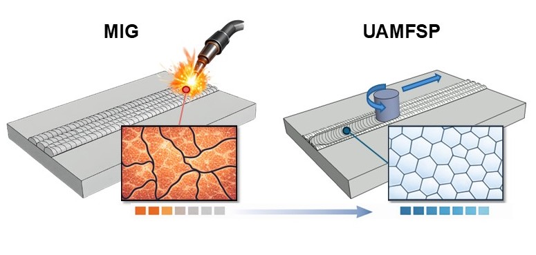
Wire Arc Additive Manufacturing (WAAM) is a cost-effective method for fabricating large aluminum components; however, it tends to suffer from heat accumulation and coarse anisotropic microstructures, which can limit the part's performance and its mechanical properties. In this study, a wall is fabricated using a hybrid unified additive deformation manufacturing process (UAMFSP) method, which integrates friction stir processing (FSP) into WAAM, and is compared with a WAAM-only wall fabricated by Metal Inert Gas (MIG) deposition. Based on the outcomes, Infrared (IR) thermography revealed progressive heat buildup in WAAM-only MIG walls, with peak layer temperatures of about 870 to 1000 °C and occasional clipped peaks near the IR-camera limit (~1300 °C). In contrast, in the UAMFSP process, heat was redistributed through mechanical stirring, maintaining more uniform sub-solidus profiles below approximately 400 °C. Also, optical microscopy and quantitative image analysis showed that MIG walls developed coarse, dendritic grains with a mean grain area of about 314 µm², whereas the UAMFSP produced refined, equiaxed grains with a mean grain area of about 10.9 µm², which is approximately 1.5 orders of magnitude smaller. Mechanical performance assessment through microhardness measurement confirmed that the UAMFSP process can improve the hardness by 45.8% compared to the MIG process (75.8 ± 7.7 HV vs. 52.0 ± 1.3 HV; p = 0.0027). In summary, the outcomes of this study introduce the UAMFSP process as a robust method for addressing the thermal and microstructural limitations of WAAM and improving the performance of the fabricated part. By combining deposition with plastic deformation, UAMFSP enables the fabrication of aluminum parts with fine isotropic microstructures and improved strength. These findings provide a framework for further extending hybrid additive-deformation strategies to thicker builds, alternative alloys, and service-relevant mechanical evaluations.
Keywords:
additive manufacturing
; aluminum alloys
; microstructure–property relationships
; wire arc additive manufacturing
; friction stir processing
; unified additive–deformation manufacturing (UAMFSP)
1. Introduction
Direct Energy Deposition Additive Manufacturing (DEDAM) processes have emerged as methods for the fabrication of near-net-shape metal parts and enable the production of complicated structures [1,2]. These processes are based on Directed Energy Deposition (DED), which uses a focused energy source for melting the feedstock, with common options such as laser beams, electron beams, and electric arc plasma. The material in the DED process can be supplied as either a powder or a wire. Wire Arc Additive Manufacturing (WAAM) is a DED-based process that has gained remarkable attention because of its cost-effectiveness, high deposition rate, and design flexibility. This technique is based on conventional welding processes, such as Metal Inert Gas (MIG), Tungsten Inert Gas (TIG), and Plasma Arc Welding (PAW) [3]. WAAM enables the production of large-scale aluminum (Al) based structures with minimal post-processing requirements, which makes it appealing for use in aerospace, automotive, and tooling applications [4,5]. Recently, it has been considered a sustainable alternative for subtractive fabrication methods due to its material efficiency, scalability, and potential for use in digital design processes [6,7].
Although WAAM has many advantages, it has some limitations. The parts fabricated by the WAAM process have dendritic microstructures [8,9], porosity, residual stresses, anisotropy, and coarse grains resulting from repetitive thermal cycles in its layer-by-layer deposition process [3,10]. These features compromise the mechanical performance by reducing the toughness, fatigue resistance, and isotropy of the fabricated part. Therefore, grain refinement is critical for improving the strength and durability of WAAM-fabricated parts. This could be done by reducing dislocation motion and enhancing Hall–Petch strengthening [11,12,13]. Furthermore, macrostructural distortions and residual stresses that result from excessive heat buildup during multilayer deposition can negatively affect the dimensional accuracy and fatigue performance of the components [14,15]. Recent studies have highlighted that effectively controlling the heat and microstructure is vital for improving the consistency of the WAAM-built aluminum components [16,17].
To address the limitations of WAAM-built parts, among the Severe Plastic Deformation (SPD) techniques, the Friction Stir Processing (FSP) is widely recognized for its ability to refine the microstructures, eliminating casting defects, and improving isotropy [13,18,19]. Derived from Friction Stir Welding (FSW), FSP has been shown to refine dendritic grains [8,9] into fine equiaxed structures, remarkably improving the strength and toughness of Al-based alloys [13,18,19]. The FSP process causes intense plastic deformation and dynamic recrystallization (DRX). This disrupts the columnar dendritic structures in the WAAM-fabricated parts, encourages the formation of high-angle grain boundaries, and helps mix solutes evenly. Recent studies have shown that using in situ interlayer FSP during WAAM can create a uniform equiaxed structure and decrease the grain size remarkably [16].
The interlayer FSP eliminates porosity and breaks eutectic phases, producing refined α-Al grains and increasing the tensile strength compared to that of WAAM-only builds [20,21]. For instance, Wei et al. [21] demonstrated that applying an interlayer FSP to the WAAM 2219 aluminum alloy improved the yield strength from 118 MPa to 143 MPa and the fatigue strength from 97 MPa to 139 MPa owing to the breakup and dissolution of coarse eutectic phases. Similarly, in Al–Cu–Mg systems, the interlayer FSP reduced porosity, refined grains to sub-5 µm, and produced nearly isotropic hardness and tensile responses [22].
Beyond FSP, new hybrid approaches, such as ultrasonic impact treatment, interlayer hot rolling, and cryogenic deformation, are being explored to simultaneously manage heat accumulation and mechanical anisotropy at the same time [23,24]. For example, interlayer ultrasonic impact increases the dislocation density and strengthens the grain boundaries while reducing the buildup of tensile residual stress [23]. Similarly, interlayer rolling and in situ electric pulse treatments decrease the residual stress and distortion without affecting geometric accuracy [25,26]. These deformation-assisted methods show that combining thermal and mechanical energy inputs can more effectively control grain shape and texture changes than optimizing the process parameters [27,28].
Recently, a patented unified additive deformation manufacturing process (UAMFSP) was proposed. This approach directly integrates WAAM with FSP to introduce a single hybrid additive–deformation process [29]. In this method, first, the WAAM stage provides a rapid material deposition, and then the FSP stage acts as SPD on the deposited material [30] to dynamically recrystallize and refine the grains during or after deposition of each layer. This method has the potential for stabilizing the thermal cycles, suppressing the abnormal grain growth, improving equiaxedness of the grains, and enhancing the mechanical properties of the fabricated part compared with the WAAM-only builds [5]. Recent research studies have supported this introduced concept. For instance, Yuan et al. [31] reported that the hybrid WAAM–interlayer FSP in Al–Cu alloys can form a periodic bimodal grain structure (BGS) that simultaneously enhances the strength and ductility of the fabricated part through combined discontinuous and continuous dynamic recrystallization (CDRX). Also, Guo et al. [32] presented that multiple stirring passes in the WAAM–FSP manufactured 2319 Al alloy part promoted secondary recrystallization and balanced strength–ductility relationships by reducing the coarsening of the remelted grain. These findings indicate that the controlled thermomechanical coupling via the iterative deposition and stirring can stabilize the heat-affected zone and also tailor the recrystallized grain size. Furthermore, in another study, Shan et al. [33] revealed that the addition of reinforcement particles during the FSP stage can result in dual strengthening and ductility in Al–Zn–Mg–Cu systems, thereby demonstrating the versatility of the hybrid fabrication approach.
Recent hybrid systems that combine the WAAM and FSP processes on a single platform have enabled improvement on controlling the heat flow and strain distribution. This integration reduces interlayer gradients of temperature and can promote a more uniform microstructure, leading to improved mechanical performance that approaches isotropy [17,27]. Studies on Al–Mg and Al–Si aluminum-based alloys have revealed the remarkable enhancements in thermal uniformity and refinement in microstructure [26,28]. The integration of the UAMFSP aligns with broader trends in hybrid manufacturing that merge additive, subtractive, and deformation processes for achieving improved structural integrity and dimensional precision [34,35,36].
The hybrid additive–subtractive systems have advantages like on-machine finishing, relief of the residual stress, and repair of defects in a single production cycle. This can reduce the production lead time and can improve repeatability [7,37]. These hybrid methods represent a paradigm shift in manufacturing, transforming WAAM from a standalone deposition process to a multifunctional platform that is capable for delivering both microstructural and geometrical excellence.
In addition, optimizing the process sequences between the FSP and heat treatment has been shown to further improve the balance between strength and ductility. For example, Zhou et al. [38] showed that the FSP followed by solution and aging of the WAAM-fabricated Al–Cu alloys can result in tensile strengths higher than 425 MPa, whereas reversing the sequence can lead to an abnormal grain growth and loss of ductility. The findings of this research emphasized that controlling the thermomechanical and thermal histories of unified systems is critical for achieving high performance.
This present study investigates the process–microstructure–property relationships of aluminum 4043 walls fabricated using WAAM-only and the patented UAMFSP processes. The analysis focuses on (i) the role of thermal accumulation during the deposition of the layers, (ii) refinement of the microstructural and statistical analysis of the grain morphology, and (iii) validation of property improvements through hardness testing [11,12]. This work introduces the UAMFSP as a robust pathway for overcoming the metallurgical and mechanical limitations of WAAM. Furthermore, it provides an experimental evidence and a conceptual framework for extending additive deformation strategies to thicker walls, alternative alloy systems, and the application-specific architectures in the future studies. The outcomes of this research are expected to contribute to a broader understanding of hybrid process coupling and the evolution of the next-generation manufacturing technologies that enable the production of high-strength, minimal-defect, and dimensionally precise Al-based components [6,22,26,39].
2. Materials and Methods
2.1. Materials
The substrate material that used in this study was an as-received commercial AA6061 aluminum alloy (purchased from Alro Metals) machined to dimensions of 152 (L) × 102 (W) × 12.7 (H) mm. The filler material used was ER4043 (an Al-Si aluminum alloy) wire (Blue Demon, 0.9 mm diameter). The nominal chemical compositions of the substrate and wire used in this study are listed in Table 1. For the deformation stage, the FSP tool was fabricated from H13 tool steel. The tool had a shoulder diameter of 18 mm and the pin diameter of 5.4 mm, with a shoulder penetration depth of 0.2 mm into the weld bead surface.
2.2. Fabrication Process
The fabrication process of this study was performed by using a HAAS VF3 CNC machining center that was retrofitted with a spool gun connected to a power source of MIG-welding. This modification enabled an automated deposition of the bead with the precise control on the welding voltage, current, wire-feed rate, and the travel speed. In the hybrid process, referred to as the UAMFSP, the FSP stage was applied between layers with controlled plunge depth, tool rotational speed, and traverse speed to induce the SPD [30,40]. The experimental setup use in this study is shown in Figure 1(a).
In this study, for performing the comparative experiments, two types of thick walls were fabricated: a MIG-only fabricated wall (baseline WAAM process) and a hybrid-fabricated UAMFSP wall. Each wall consisted of three layers with four overlapping beads per layer and a 50% overlap between adjacent beads. Room-temperature cooling intervals were introduced between successive layers until the interlayer temperature decreased to 38–40 °C, thereby minimizing the excessive heat accumulation [41,42]. Figure 1(b) shows the two types of walls, and the fabrication sequence of the walls using the UAMFSP process is illustrated in Figure 1(c). For clarity, the first type of wall was produced using only the initial stage of UAMFSP, namely MIG deposition, whereas the second type of wall was fabricated using the complete two-step UAMFSP route, comprising MIG deposition followed by FSP.
The wire tip–substrate gap was fixed at 6 mm to ensure the stability of the arc. The wire feeding rate was controlled with the welding current, and pure (99%) argon was used as the shielding gas. The MIG welding process parameters are summarized in Table 2, and the FSP parameters are presented in Table 3.
Specimens were extracted from both the MIG and the UAMFSP walls for a comparative analysis. Synchronizing MIG deposition with the FSP step was challenging because of the difference in processing speeds; therefore, the second stage of the process (FSP) was initiated only after the temperature of the deposited layer decreased to 38–40 °C.
2.3. Fabrication Process
For microstructural analysis, the specimens were prepared using standard metallographic procedures, including hot mounting, sequential polishing with progressively finer abrasive papers, ultrasonic cleaning, cloth polishing with aluminum oxide powder, and final polishing with a colloidal silica suspension. The polished surfaces were etched with Keller’s reagent to reveal grain boundaries. The specimens were extracted perpendicular to the x-axis from each layer to obtain representative samples across the build height. The sectioning locations and orientations of the specimens are shown in Figure 2(a).
The prepared specimens were first examined with a 3D laser scanning microscope (VK-9700, KEYENCE) for evaluating the quality of their surface, followed by detailed microstructural imaging. The acquired image datasets were processed employing the MIPAR software (MIPAR Image Analysis, Columbus, OH, USA) for isolating the grain boundaries and quantifying the grain metrics, like the grain area and perimeter. The outputs were then further analyzed utilizing a custom MATLAB script for evaluating the grain size distributions, roundness, and power-law fitting. Figure 2(b) depicts a representative image showing MIPAR-based microstructural analysis.
2.4. Thermal Monitoring
The thermal history during the fabrication process of the walls was captured employing an FLIR T300 infrared (IR) camera (Teledyne FLIR) to monitor and record the real-time temperature profiles. The camera provided a resolution of 76,800 pixels (320 × 240), a standard temperature range of −20 °C to 650 °C (upgraded to 1300 °C), and an accuracy of ±2%. Before use, the system was calibrated against a MIKRON M330 high-temperature blackbody source at distances of 500 and 1000 mm, resulting in deviations of 8 °C at 1000 mm and 19–22 °C at 500 mm from the actual temperatures. These deviations were acceptable for the expected temperature range (up to 450 °C). During the experiments, the camera was positioned 500 mm from the substrate, focusing on the deposition and FSP zones in a side-view orientation (Figure 2(c)) and connected to a laptop running the FLIR Tools+ software. The temperature fields over time under the MIG and UAMFSP conditions were recorded at a frame rate of 10 fps. The software was employed for recording radiometric videos, extracting temperature–time histories, and generating radiometric images for the correlation with the microstructural analyses
2.5. Mechanical Testing
For evaluating the mechanical performance, the Vickers microhardness measurements were performed on the samples, employing a Tukon 2100 Micro indentation Hardness Tester (Wilson Instruments, division of Instron Corporation, USA). For the hardness measurement, the specimens were prepared according to the ASTM E3 metallographic standards, including sectioning, phenolic mounting, sequential grinding (240 to 1200 grit), and polishing with the diamond suspensions (6–1 µm), followed by a final polishing with 0.05 µm colloidal silica. For ensuring the integrity, the samples were cleaned ultrasonically, gently etched with Keller's reagent, and examined under an optical microscope. The hardness measurement experiments were performed on the polished cross-sections at the ambient temperature, while maintaining a uniform spacing within the microstructural regions to ensure representative and reproducible measurements.
3. Results
In this section, the outcomes of comparative evaluation of the MIG and the UAMFSP walls in terms of their microstructural specifications, thermal history during their manufacturing process, and their resulting mechanical performance are presented.
3.1. Microstructural Analysis
As discussed earlier in the previous section, two types of thick aluminum walls were fabricated for the comparison: a WAAM baseline wall produced solely by MIG deposition and a hybrid wall produced using the UAMFSP method, which integrated MIG deposition with FSP. The quantitative analysis of the captured images was employed for evaluating the effects of the processing routes on the microstructural evolution. Representative optical micrographs of two types of walls are presented in Figure 3.
Based on the analysis, the MIG wall revealed an evolution in the grain morphology across the build height. In Layer 1 (L1) of the MIG fabricated sample, the grains were comparatively coarse, elongated, and partially dendritic, with irregular boundaries, while in Layer 2 (L2), the grains exhibited a partial refinement and spheroidization of the dendritic arms in comparison to L1, suggesting the influence of the repeated thermal cycling. In Layer 3 (L3), the progressive heat accumulation [41,42] led to a further coarsening of grains with irregular morphologies, which is consistent with the repeated reheating during the process of deposition.
In contrast, the UAMFSP wall displayed significantly more refined and homogeneous microstructures across all the layers. As can be observed in Figure 3, in layers 1 to 3, the grain morphology remained predominantly fine and equiaxed, which reflects the combined influence of plastic deformation [30,40] and localized DRX [43,44,45] induced by the FSP. The observed consistent grain size and uniform structure confirmed the strong grain-refinement capability of the UAMFSP process, which can mitigate the thermal coarsening and can improve the microstructural stability.
For the quantification of the microstructural observations, the grain size and shape parameters were statistically analyzed. The analyzed outcomes are summarized in Table 4. Based on these results, the MIG wall exhibited a mean grain area of 313.6 µm² with a median of 219.9 µm², which confirms the dominance of large grains with a broad distribution of grain sizes. The high standard deviation of the grain area (335.2 µm²) indicates a significant heterogeneity in the grains of the MIG-fabricated wall. Also, the mean grain perimeter was 73.4 µm with a standard deviation of 49.6 µm, which further confirm the irregular and elongated boundary morphology of the grains. Furthermore, the mean equivalent diameter of the grains was 17.2 µm, while the mean roundness of the grains (0.71 ± 0.38) further revealed the presence of the elongated dendritic features rather than equiaxed grains.
In contrast, the UAMFSP-fabricated wall exhibited a refined and uniform microstructure. The mean grain area was 10.9 µm², with a median of 6.4 µm², with a much smaller standard deviation (13.1 µm²), which confirms a tightly clustered distribution of the grain areas. Also, the mean grain perimeter was decreased to 14 µm (σ = 9.5 µm), and the mean equivalent diameter was reduced to 3.2 µm, with a significant refinement compared with the MIG wall. Although the mean roundness (0.62 ± 0.29) was comparable to that of MIG, the reduced deviation indicated a more consistent and isotropic grain shape.
Figure 4 shows the distributions of the probability density of the grain area, grain perimeter, grain equivalent diameter, and grain roundness for the MIG and the UAMFSP walls. Also, Figure 5 compares these distributions, which highlights the pronounced grain refinement and improved morphological uniformity that have been achieved in the UAMFSP-fabricated wall.
The presented outcomes show wide spread of elongated and irregular grains in the MIG wall. These characteristics are consistent with progressive interlayer heat accumulation [41,42], which promotes the Ostwald ripening and dendritic growth [8,9] along the thermal gradient. In contrast, for the UAMFSP wall, the narrow and uniform distributions of dense clusters of fine equiaxed grains were observed. These results, including about a 1.5-order-of-magnitude reduction in the mean grain area (from 313.6 µm² in the MIG wall to 10.9 µm² in the UAMFSP wall), are consistent with the role of the FSP in promoting DRX [43,44,45], fragmenting dendritic grains [8,9], redistributing boundaries, and enhancing isotropy
3.2. Thermal Behavior
The thermal evolution of the MIG and the UAMFSP walls was monitored using the infrared (IR) thermography imaging. Representative temperature contour maps obtained by IR thermography are presented in Figure 6, illustrating the spatial temperature distribution across the layers 1 to 3, corresponding to L1 at 60 s, L2 at 50 s, and L3 at 30 s after the start of each layer's deposition or processing. As shown in the figure, the MIG wall exhibited the broad and intense high-temperature zones that expanded with the build height, that indicate progressive interlayer heat accumulation. In contrast, the UAMFSP wall maintained the uniformly distributed low-intensity contours, that reflect superior thermal management and minimal residual heating.
As can be observed, Figure 6 reveals that the layers in the MIG wall that are shown in the left column have a higher maximum temperature with a broader distributions. The peak values reach to approximately 600 °C in layers 1 to 3. This indicates substantial heat accumulation and a reduced cooling efficiency along the successive depositions in the MIG wall. On the other hand, the layers in the UAMFSP wall, that are shown in the right column, maintained lower and more uniform temperature fields, with the peak temperatures of about 300 °C across all layers, reflecting efficient thermal dissipation and localized heat generation in the interface of the tool and the sample. This comparison highlights that the UAMFSP process can significantly reduce the overall heat input and can mitigate interlayer thermal buildup, compared to the conventional MIG deposition. This reduction in the maximum and residual temperatures can improve the microstructural uniformity and prevent the defects that could be induced by overheating. These results confirm the capability of hybrid deposition–deformation strategies in redistributing the heat and mitigating the thermal gradients [30,40]. The distinct temperature regimes align with the refined grain structures observed in Section 3.1, that confirm the reduced thermal exposure in the UAMFSP process can promote stable and fine-grained microstructures.
As the temperature contour maps shown in Figure 6 represent the instantaneous thermal states at selected time points, they do not capture the complete temporal evolution of heat accumulation during the whole process. To address this limitation, the variations in the maximum temperature with time throughout the entire deposition and processing sequence for layers 1 to 3, in both the MIG and UAMFSP walls, are presented in Figure 7. As shown in this figure, the MIG condition exhibited sharp, repeated temperature spikes corresponding to arc ignition and droplet transfer events, followed by brief cooling intervals between the passes. The observed fluctuating temperature profile for the MIG wall indicates an unstable heat input and significant thermal cycling, which is consistent with the melting–solidification behavior of the MIG process during the welding. In contrast, the UAMFSP condition was demonstrating a much smoother and more stable thermal curve, with the peak temperatures being maintained at around 300 to 400 °C for all the layers. The absence of abrupt spikes confirms that the heat generation in the UAMFSP wall is governed mainly by frictional and plastic deformation mechanisms rather than the melting. This steady-state temperature evolution reflects effective heat redistribution and rapid dissipation during the hybrid processing, which minimizes interlayer thermal gradients and prevents excessive local heating.
As shown in the Figure 7, for the MIG wall, the thermal profiles, that was recorded by the IR camera, occasionally displayed clipped peaks near the maximum measurable temperature of 1300 °C. This saturation suggests that the localized regions (particularly within an arc core and molten droplets) temporarily reached the temperatures higher than the calibrated range. This transient overheating is characteristic for the aluminum 4043 MIG welding, where the arc plasma and the molten pool can reach into highly elevated temperatures [46]. Although these extreme values were not fully captured, the clipped peaks on the plots are confirming their occurrence. However, this limitation does not affect the comparative analysis as the UAMFSP condition peak temperatures remain within the solid-state temperature range, that ensure a reliable differentiation between the melting-based MIG and FSP processes.
Figure 8 and Table 5 show a comparison of the maximum temperatures measured through layers 1–3 for the MIG and UAMFSP walls. The results demonstrated that the MIG process generated significantly higher peak temperatures at all layers than the UAMFSP process. Specifically, the mean maximum temperatures for the MIG ranged from 869.4 °C to 998.2 °C, whereas the UAMFSP showed much lower temperatures ranging from 277.2 °C and 386.2 °C. Based on the t-test analysis, this difference was statistically significant for each layer (****p < 0.0001)). The standard deviations were also remarkably higher for the MIG wall (384–426 °C) than for the UAMFSP wall (55–96 °C), indicating higher thermal fluctuations and non-uniform heating during conventional MIG deposition. In contrast, the temperature in the fabrication of the UAMFSP wall had more stable and controlled conditions, which can be helpful for decreasing residual stresses, reducing microstructural heterogeneity, and decreasing potential metallurgical defects in the fabricated wall. The results revealed that the integration of the FSP stage in the UAMFSP process effectively suppressed excessive heat accumulation and promoted a more uniform thermal profile, contributing to improved process stability and microstructural refinement compared with conventional MIG deposition.
3.3. Mechanical Properties
The mechanical responses of the two walls were evaluated through the Vickers microhardness testing (HV0.2), following the procedure described earlier. Figure 9 presents graphically the measured mean hardness values and their corresponding standard deviations for the MIG and the UAMFSP conditions. As can be seen in this figure, the MIG wall exhibited an average hardness of 52.0 ± 1.3 HV, indicating a relatively low strength, consistent with the aluminum structures fabricated by the conventional wire-arc deposition. In comparison, the UAMFSP wall achieved a hardness of 75.8 ± 7.7 HV, corresponding to an increase of 45.8% compared to the MIG wall. Statistical analysis (t-test, p = 0.0027) confirmed that this improvement in the UAMFSP wall was statistically significant compared to MIG wall, as indicated by the double asterisks in Figure 9.
Similar improvements in hardness through grain refinement have been reported in aluminum alloys in previous studies, where Hall–Petch strengthening dominates the structure–property relationship [1,11,12]. The enhancement in the hardness of the UAMFSP wall reflects the combined effects of the fine equiaxed grains, the improved isotropy, and the enhanced boundary density that were produced by the DRX [43,44,45].
Although the UAMFSP wall displayed a slightly higher scatter in the hardness values, this variability remained within the typical range expected for the hybrid additively processed aluminum components. Overall, the UAMFSP condition exhibited the consistently higher hardness across the measured regions compared to the MIG wall. A detailed interpretation of the strengthening mechanisms and their relationship with the refined microstructure is provided in the Discussions section.
4. Discussions
4.1. Microstructural Analysis
The earlier presented microstructural analysis results emphasize the important role of the processing strategy in controlling the microstructure. The contrast in the evolution of the microstructures between the conventional MIG-deposited wall and the hybrid UAMFSP wall highlights the mechanisms governing grain coarsening, refinement, and the recrystallization in these two processes.
For the MIG wall, the progressive coarsening quantified in Table 4 and shown in Figure 3, along with the broad statistical spread reported in Table 4 and Figs. 4 and 5, can be attributed to the interpass heat accumulation [41,42] during the successive deposition of the layers. The repeated reheating of already solidified layers encourages Ostwald ripening and dendritic grain alignment [8,9] through the prevailing thermal gradient, resulting in anisotropic and heterogeneous microstructures. A similar behavior has been reported in WAAM-fabricated aluminum alloys, where heat accumulation causes abnormal grain growth and lower structural uniformity [41,42]. The presence of coarse, irregular grains in the MIG-deposited wall can increase the likelihood of the formation of a stress concentration site, thereby reducing fatigue resistance and declining the overall mechanical reliability [8,9]. The heterogeneous structure of the MIG wall, characterized by a mean grain area of 313.6 µm² and a high standard deviation of 335.2 µm², implies a strong spatial variation in the local solidification rates, in line with the reports on WAAM aluminum alloys, where the variable thermal gradients lead to uneven grain morphologies and the solidification behaviors [47]. These coarse, irregular grains are likely acting as the stress concentrators under the cyclic loading, which can reduce the fatigue strength and the reliability [48,49]. Therefore, the MIG microstructure typifies a thermally dominated WAAM system in which high peak temperatures and thermal cycling govern the grain coarsening.
In contrast, the UAMFSP wall exhibited comparatively refined, equiaxed, and isotropic grains across all build layers, as shown in Figure 3. The outcomes revealed that the average grain area was decreased by about 1.5 orders of magnitude (from 313.6 µm² to 10.9 µm²) compared to that of the MIG-deposited wall. This improvement is consistent with the mechanisms of the FSP, where SPD [30,40] thermal stirring fragments dendritic grains [8,9] and drives dynamic recrystallization (DRX) [43,44,45,50,51]. The tight statistical distributions and equiaxed morphologies validate that the FSP stage in the UAMFSP process can help to mitigate anisotropy and achieve uniform grain refinement, which is consistent with previous studies on hybrid additive–deformation processes [30,40]. Additionally, the combination of moderate thermal input (300 to 400 °C, as shown in Figure 8) and rapid heat dissipation prevents the abnormal grain growth, that produces stable subgrain structures with the high-angle boundaries [50,51,52]. This microstructural stability can explain the narrow statistical spread of the grain size (σ = 13.1 µm²) and perimeter (σ = 9.5 µm) in the UAMFSP fabricated wall. The observed isotropy and grain uniformity suggest that the thermomechanical environment during the FSP stage of the UAMFSP process can effectively mitigate the thermal gradients while maintaining a controlled deformation-driven recrystallization regime. These results agree with those of hybrid FSP-assisted WAAM systems reported for aluminum alloys [17,22,31,53,54,55,56,57,58], in which post-deposition or interlayer FSP reduced porosity, homogenized solute distribution, and significantly refined the structure of the grain.
The DRX during the FSP stage of the UAMFSP process can introduce the high-angle grain boundaries that act as dislocation barriers, and frictional heat exposure below the solidus temperature promotes fine sub-grain formation without coarsening. These mechanisms collectively stabilize the dislocation structures and can improve the strain accommodation. The intimate coupling of the frictional heating and plastic flow can create the favorable conditions for CDRX, leading to refined, equiaxed, and defect-free grain structures. Figure 10 schematically depicts the grain refinement mechanism in UAMFSP via CDRX. The rotating FSP tool refined the MIG-deposited layer into fine, equiaxed grains.
The achieved grain refinement ratio (~29× decrease in the mean grain area) is consistent with the reported DRX refinement factors for FSP-processed aluminum alloys [53]. Furthermore, the observed homogeneity across layers 1–3 indicates that the UAMFSP overcomes the common limitation of WAAM, namely, the microstructural gradient along the build direction [31]. Similar hybrid approaches, such as interlayer hot rolling [59] and in-situ friction stir additive manufacturing [52], have also demonstrated the isotropic and high-strength outcomes by controlling the thermomechanics of their relevant process. Therefore, the present study confirms that integrating a solid-state deformation step directly after deposition is an effective strategy for stabilizing the microstructure and enhancing the structural integrity of aluminum alloy WAAM components.
4.2. Thermal Behavior
The thermal profiles, that were presented in Section 3.2, highlighted the divergent heat management between the MIG and the UAMFSP walls. In the MIG condition, progressive heat accumulation [41,42] was observed in each layer. Such accumulation is characteristic of WAAM processes without interpass cooling, where a high heat input promotes reduced cooling rates and localized reheating [41,42]. The IR thermography results showed broad, intense high-temperature zones extending through the wall height, with mean peak temperatures between 869 and 998 °C and standard deviations of approximately 384–426 °C, as shown in Table 5.
The microstructural transformations discussed earlier correlate with the distinct thermal history of the two processing routes. The MIG wall experienced extreme and fluctuating maximum temperatures between about 900 to 1000 °C, occasionally exceeding the calibrated limit of the IR camera, that was about 1300 °C, whereas the UAMFSP wall maintained stable peak temperatures below 400 °C (Figs. 7 and 8). This reduction in the temperature amplitude minimizes solute diffusion and grain coarsening kinetics [60]. Figure 8 confirms that the peak temperature is lower than 400 °C, which is fairly below the Al-Si eutectic (~577 °C) [61], which can prevent remelting and preserve the solid-state nature of the FSP. The lower and more uniform heat input during the FSP stage of the UAMFSP process enhanced heat dissipation through the substrate and tool shoulder, reducing the residual heat and suppressing the epitaxial grain growth.
Occasional clipped peaks near the IR camera limit of about 1300 °C indicate transient local overheating during arc ignition and droplet transfer, which is a known feature of aluminum MIG deposition [46]. Such thermal nonuniformity produces steep gradients along the build direction, which provides a driving force for anisotropic grain growth via dendritic alignment [8,9]. This mechanism explains the anisotropic coarsened morphologies observed in the Figure 3 and is consistent with prior studies on the WAAM process that link the excessive interpass temperatures to the abnormal grain growth, residual stresses, and microstructural heterogeneity [57].
The UAMFSP wall exhibited peak temperatures below 400 °C with the uniform contours and moderate cooling rates throughout all layers. Mechanical stirring during the FSP stage of the UAMFSP process redistributes the heat, limits the extreme gradients, and prevents the localized overheating. The friction-stir caused convection can enhance the heat dissipation through the shoulder and substrate, which maintains the material well below the melting range, and prevents the interlayer thermal buildup. The lower and more uniform temperatures (mean approximately 277–386 °C with standard deviations 55–96 °C) confirm the stabilized thermal regime achieved through the FSP stage in the UAMFSP process. This steady-state heating mode helps minimize the residual stresses, mitigating the thermal gradients, and providing favorable conditions for CDRX, accounting for the refined equiaxed grains observed in the Figure 3. The stark contrast between these two regimes of the temperature underscores the fundamental differences in the mechanisms of heat generation. Similar redistribution mechanisms have been reported in the hybrid additive–deformation processes [50,51,62], where SPD [30,40] reduces thermal accumulation and stabilizes microstructural development.
MIG deposition is dominated by the arc-based melting and solidification, which can produce sharp thermal spikes and steep gradients, whereas the FSP stage in the UAMFSP process is based on distributed frictional and plastic work heating, which generates a lower-magnitude, spatially uniform temperature field. Consequently, the UAMFSP process integrates both thermal and mechanical stabilization, ensuring a controlled solid-state thermal cycle that can suppress overheating and enhance the reproducibility of the process. These results are consistent with those of earlier hybrid-WAAM investigations [51], which demonstrated that the active control of the interlayer temperature effectively improves the microstructural uniformity, hardness, and the overall build integrity.
4.3. Mechanical Properties
The outcomes of microhardness measurements further validated the microstructural differences between the MIG and the UAMFSP walls. Grain refinement plays a crucial role in the mechanical performance of the metallic materials. According to the Hall–Petch relationship, the yield strength increases inversely with the square root of the grain size, that indicates the smaller grains can provide higher resistance to the motion of dislocation along the grain boundaries [63]. In this context, the substantial grain size reduction achieved through the UAMFSP process led to a notable improvement in the yield strength compared to that of the coarse-grained MIG-deposited wall. As the hardness value is directly correlated to the yield strength, this microstructural refinement also manifests as a measurable increase in hardness values, which confirms the strengthening effect of fine equiaxed grains produced by DRX [63].
The MIG wall, with the measured hardness of 52.0 ± 1.3 HV, displayed a comparatively low value of hardness that confirms the coarse dendritic microstructures [8,9] and residual anisotropy typical of aluminum components fabricated by the conventional WAAM method [1,11,12]. The limited grain boundary density and the presence of elongated, irregular grains (as can be observed in Table 4) reduced the effectiveness of dislocation hindrance, that lead to a lower hardness and strength. This behavior aligns with earlier reports that insufficient thermal control during arc-based deposition produces heterogeneous microstructures with localized stress concentrations, which then diminish the mechanical efficiency and fatigue reliability [58].
On the other hand, the UAMFSP sample exhibited hardness values of 75.8 ± 7.7 HV, corresponding to an increase of ~45.8 % compared with the MIG condition (p = 0.0027; Figure 9). This improvement can be mainly attributed to Hall–Petch strengthening, whereby the finer grain sizes (from ~17.2 µm to ~3.2 µm) increase the resistance to dislocation motion [1,11,12]. Although the UAMFSP wall displayed slightly higher scatter in the hardness values, this variation remained within the typical range reported for the hybrid additive–deformation aluminum systems [50,51,62]. The intense plastic deformation and thermal–mechanical coupling during FSP produced a more refined equiaxed grain structure with an increased boundary density and uniform crystallographic orientation. Moreover, the equiaxed and isotropic microstructures produced by the FSP minimize the anisotropy, enhance the uniform mechanical response, and reduce the likelihood of microcrack initiation.
Figure 11 shows the dominant strengthening mechanism. As illustrated, in the MIG wall, coarse dendritic grains allowed long dislocation glide paths (red arrows), resulting in a low hardness of about 52 HV. On the other hand, in the UAMFSP wall, with a hardness value of about 76 HV, the ultrafine equiaxed grains generate dense dislocation pile-ups (blue arrows) on high-angle boundaries, which can increase the resistance to slip, a direct manifestation of Hall–Petch strengthening.
Comparable hardness and strength have been reported for hybrid FSP-assisted WAAM fabricated aluminum alloys, where the interlayer deformation transformed columnar grains into fine equiaxed morphologies and enhanced both the yield strength and fatigue endurance [52,62]. For example, Zhou et al. [50] reported that Al–Cu–Sc alloys processed by the FSP-assisted WAAM process exhibited substantial yield and ultimate strength gains of about 30% compared to as-deposited walls. Also, Sun et al. [51] similarly demonstrated that an interlayer FSP can eliminate the metallurgical defects, such as porosity, refine grains, and redistribute Al₂Cu precipitates, collectively can improve the tensile strength and ductility while also promoting the isotropic behavior.
Collectively, the results of the mechanical performance evaluation using microhardness measurement confirm that the UAMFSP process can successfully overcome the characteristic limitations of the conventional WAAM process by producing fine-grained isotropic walls with enhanced strength and improved reliability.
4.4. Implications and Final Remarks
The earlier presented comparative findings highlight that the processing strategy plays a vital role in governing the process–structure–property relationships of aluminum alloy walls fabricated using MIG-only and the hybrid UAMFSP routes. In the MIG wall, the dominance of course, irregular, and partially dendritic grains reflected the cumulative effects of interpass heat accumulation and slow solidification. These structural characteristics can foster the anisotropy [8,9], localized stress concentrations, and the nonuniform mechanical behavior, which collectively can degrade the toughness, fatigue life, and strength. These limitations are consistent with those of prior studies on the WAAM process, which reported that uncontrolled thermal cycling and remelting can lead to the uniform and heterogeneous microstructures, high residual stresses, and premature fatigue cracking [22,58]. In contrast, the UAMFSP-fabricated wall exhibited refined, equiaxed, and isotropic microstructures accompanied by significantly lower and more uniform peak temperatures.
These thermal and structural refinements have been translated directly to superior mechanical properties, as evidenced by a 45.8 % hardness increase. The hybrid WAAM construction exploits the geometric freedom of additive processes while retaining the mechanical robustness of conventional manufacturing [59]. This principle underpins the UAMFSP strategy, which couples layer-wise deposition with solid-state deformation to achieve the design flexibility and structural reliability of the fabricated parts. This enhancement can be ascribed to Hall–Petch strengthening [53,63] arising from the reduced grain size in combination with the isotropic and defect-minimized microstructure achieved by the FSP. Such simultaneous refinement and homogenization are consistent with earlier hybrid FSP-assisted WAAM investigations on different aluminum alloys, which reported parallel improvements in hardness, yield strength, and fatigue endurance [22,51,62].
Overall, the results confirm that coupling MIG deposition with FSP overcomes the limitations of conventional WAAM and establishes a robust process–structure–property relationship. These outcomes are aligned with our group’s patented vision for hybrid manufacturing [29], which integrates deposition, deformation, and machining into a single thermomechanically balanced workflow to achieve reproducible, isotropic, and high-performance components.
Collectively, these findings establish the UAMFSP approach as a robust, scalable, and thermomechanically balanced pathway to fabricate aluminum alloy components that need high structural integrity, isotropy, and reliability, which are key prerequisites for aerospace, marine, and automotive applications, where the conventional WAAM is constrained by anisotropy and heat-accumulation effects [59].
5. Conclusion
This study demonstrated that the processing strategy exerts a decisive influence on the thermal, microstructural, and mechanical characteristics of aluminum-alloy walls fabricated using the MIG and the hybrid UAMFSP processes.
The microstructural results confirmed that the MIG-deposited walls developed coarse, dendritic, and anisotropic grains (mean area of about 313.6 µm²), which was a direct consequence of uncontrolled solidification and thermal gradients. However, the walls fabricated using the UAMFSP process exhibited a refined, equiaxed, and isotropic structure that had a mean grain area of 10.9 µm², attributed to the SPD and DRX during the FSP stage of the UAMFSP process. This transition from the melting–solidification process to solid-state recrystallization significantly improved the grain uniformity and eliminated the anisotropy typical of WAAM-deposited aluminum structures.
The thermal analysis revealed that the MIG wall experienced a progressive heat accumulation for each successive layer, where the maximum temperatures of about 900 to 1000 °C were recorded during the process, and the transient peaks occasionally exceeded the limit of the highest measurable temperature of the IR camera, which was approximately 1300 °C. In contrast, the UAMFSP process effectively redistributed the frictional heat through plastic stirring, which maintains the peak temperatures below 400 °C and ensures more uniform and stable temperature fields along the build line.
Mechanical characterization further supported the previous observations. The UAMFSP walls achieved a hardness of 75.8 ± 7.7 HV, which represents an approximately 45.8% increase compared to the MIG walls, which showed a hardness of 52.0 ± 1.3 HV. This improvement is governed by the Hall–Petch relationship, in which a refined grain size and isotropic microstructure can increase the resistance to dislocation motion and improve the overall mechanical performance. These results reveal that the UAMFSP process can provide a strong and reproducible pathway for overcoming the inherent thermal and microstructural limitations of the conventional WAAM, resulting in fine-grained, isotropic, and mechanically stable aluminum walls.
Overall, the results of this study demonstrate that the hybrid UAMFSP process is a robust approach for overcoming the inherent thermal and microstructural limitations of the WAAM process, which enables the fabrication of the high-performance aluminum components. For a broader industrial adoption, the future research should extend this approach into thicker multilayer builds, explore additional aluminum alloys and hybrid material systems, and investigate about their performance under the service-relevant loading conditions, such as tensile, fatigue, and the thermal cycling. Such a research study is essential for establishing the scalability, the durability, and the qualification potential of the UAMFSP as a reliable manufacturing route for the high-performance structural components used in aerospace, marine, and automotive applications.
Author Contributions
Conceptualization, A.E. and X.W.; methodology, A.E.; software, A.E.; validation, A.E., Y.Y. and X.W.; formal analysis, A.E.; investigation, A.E.; resources, A.E.; data curation, A.E.; writing—original draft preparation, A.E.; writing—review and editing, A.E.; visualization, A.E.; supervision, X.W.; project administration, A.E.; funding acquisition, X.W. All authors have read and agreed to the published version of the manuscript.
Funding
This research received no external funding
Data Availability Statement
Data supporting the findings of this study are available from the corresponding author upon reasonable request.
Acknowledgments
The authors acknowledge the support of Wayne State University and the Department of Mechanical Engineering at Wayne State University. The authors also thank Dr. Husam Alrihili, and Dr. Pawan Vedanti their technical assistance during the experiments.
Conflicts of Interest
The authors declare no competing financial interests or personal relationships that could influence the work reported in this study.
Abbreviations
The following abbreviations are used in this manuscript:
| AA | Aluminum Alloy |
| AM | Additive Manufacturing |
| BGS | Bimodal Grain Structure |
| CDRX | Continuous Dynamic Recrystallization |
| DED | Directed Energy Deposition |
| DEDAM | Direct Energy Deposition Additive Manufacturing |
| DOE | Design of Experiments |
| DRX | Dynamic Recrystallization |
| ER4043 | Al–Si welding wire/filler alloy (AWS designation) |
| FSP | Friction Stir Processing |
| FSW | Friction Stir Welding |
| HV | Vickers Hardness |
| IR | Infrared |
| MIG | Metal Inert Gas |
| PAW | Plasma Arc Welding |
| SPD | Severe Plastic Deformation |
| TIG | Tungsten Inert Gas |
| UAMFSP | Unified Additive–Deformation Manufacturing Process |
| WAAM | Wire Arc Additive Manufacturing |
Symbols/Variables
The following Symbols/Variables are used in this manuscript:
| Symbol | Description | Unit |
| σA | Standard deviation of grain area | µm² |
| σDeq | Standard deviation of equivalent diameter | µm |
| σP | Standard deviation of grain perimeter | µm |
| σR | Standard deviation of grain roundness | - |
| A | Grain area | µm² |
| Ā | Mean grain area | µm² |
| Ã | Median grain area | µm² |
| Deq | Grain equivalent diameter | µm |
| D̄ | Mean equivalent diameter | µm |
| D̃ | Median equivalent diameter | µm |
| HV | Vickers microhardness | - |
| I | Welding current | A |
| L1, L2, L3 | Layer 1, Layer 2, Layer 3 (build sequence) | - |
| P | Grain perimeter | µm |
| P̄ | Mean grain perimeter | µm |
| P̃ | Median grain perimeter | µm |
| R | Grain roundness | - |
| R̄ | Mean grain roundness | - |
| R̃ | Median grain roundness | - |
| T( | Temperature field at position ( | °C |
| U | Welding voltage | V |
| v | Tool/substrate travel speed | mm·min⁻¹ |
References
- Montevecchi, F.; Venturini, G.; Grossi, N.; Scippa, A.; Campatelli, G. Idle Time Selection for Wire-Arc Additive Manufacturing: A Finite Element-Based Technique. Additive Manufacturing 2018, 21, 479–486. [CrossRef]
- Ayarkwa, K.F.; Williams, S.W.; Ding, J. Assessing the Effect of TIG Alternating Current Time Cycle on Aluminium Wire + Arc Additive Manufacture. Additive Manufacturing 2017, 18, 186–193. [CrossRef]
- Li, S.; Zhang, L.-J.; Ning, J.; Wang, X.; Zhang, G.-F.; Zhang, J.-X.; Na, S.-J. Microstructures and Mechanical Properties of Al–Zn–Mg Aluminium Alloy Samples Produced by Wire + Arc Additive Manufacturing. Journal of Materials Research and Technology 2020, 9, 13770–13780. [CrossRef]
- IvánTabernero; Paskual, A.; Álvarez, P.; Suárez, A. Study on Arc Welding Processes for High Deposition Rate Additive Manufacturing. Procedia CIRP 2018, 68, 358–362. [CrossRef]
- Oliveira, J.P.; Santos, T.G.; Miranda, R.M. Revisiting Fundamental Welding Concepts to Improve Additive Manufacturing: From Theory to Practice. Progress in Materials Science 2020, 107, 100590. [CrossRef]
- Zhang, H.; Li, R.; Liu, J.; Wang, K.; Weijian, Q.; Shi, L.; Lei, L.; He, W.; Wu, S. State-of-Art Review on the Process-Structure-Properties-Performance Linkage in Wire Arc Additive Manufacturing. Virtual and Physical Prototyping 2024, 19, e2390495. [CrossRef]
- Freitas, B.; Richhariya, V.; Silva, M.; Vaz, A.; Lopes, S.F.; Carvalho, Ó. A Review of Hybrid Manufacturing: Integrating Subtractive and Additive Manufacturing. Materials (Basel) 2025, 18, 4249. [CrossRef]
- Li, J.L.Z.; Alkahari, M.R.; Rosli, N.A.B.; Hasan, R.; Sudin, M.N.; Ramli, F.R. Review of Wire Arc Additive Manufacturing for 3D Metal Printing. International Journal of Automation Technology 2019, 13, 346–353. [CrossRef]
- Chaturvedi, M.; Scutelnicu, E.; Rusu, C.C.; Mistodie, L.R.; Mihailescu, D.; Subbiah, A.V. Wire Arc Additive Manufacturing: Review on Recent Findings and Challenges in Industrial Applications and Materials Characterization. Metals 2021, 11, 939. [CrossRef]
- Liu, J.; Xu, Y.; Ge, Y.; Hou, Z.; Chen, S. Wire and Arc Additive Manufacturing of Metal Components: A Review of Recent Research Developments. Int J Adv Manuf Technol 2020, 111, 149–198. [CrossRef]
- Singh, S.R.; Khanna, P. Wire Arc Additive Manufacturing (WAAM): A New Process to Shape Engineering Materials. Materials Today: Proceedings 2021, 44, 118–128. [CrossRef]
- Wu, B.; Pan, Z.; Ding, D.; Cuiuri, D.; Li, H.; Xu, J.; Norrish, J. A Review of the Wire Arc Additive Manufacturing of Metals: Properties, Defects and Quality Improvement. Journal of Manufacturing Processes 2018, 35, 127–139. [CrossRef]
- Geng, H.; Li, J.; Xiong, J.; Lin, X. Optimisation of Interpass Temperature and Heat Input for Wire and Arc Additive Manufacturing 5A06 Aluminium Alloy. Science and Technology of Welding and Joining 2017, 22, 472–483. [CrossRef]
- Gurmesa, F.D.; Lemu, H.G.; Adugna, Y.W.; Harsibo, M.D. Residual Stresses in Wire Arc Additive Manufacturing Products and Their Measurement Techniques: A Systematic Review. Applied Mechanics 2024, 5, 420–449. [CrossRef]
- Vishwanath, N.; Suryakumar, S. Residual Stress and Distortion Control in Wire-Arc Additive Manufacturing Process through Novel Modular Substrate. Proceedings of the Institution of Mechanical Engineers, Part E: Journal of Process Mechanical Engineering 2024, 238, 1570–1579. [CrossRef]
- He, C.; Wei, J.; Li, Y.; Zhang, Z.; Tian, N.; Qin, G.; Zuo, L. Improvement of Microstructure and Fatigue Performance of Wire-Arc Additive Manufactured 4043 Aluminum Alloy Assisted by Interlayer Friction Stir Processing. Journal of Materials Science & Technology 2023, 133, 183–194. [CrossRef]
- Badri, E.; Shamsipur, A.; Abdollahzadeh, A. AlMg/SiC Nanocomposite Thin Wall via Hybrid Wire Arc Additive Manufacturing and Friction Stir Processing: Investigation of Microstructural, Mechanical, Tribological, and Electrochemical Properties. Journal of Materials Research and Technology 2025, 38, 2690–2706. [CrossRef]
- Guan, R.-G.; Tie, D. A Review on Grain Refinement of Aluminum Alloys: Progresses, Challenges and Prospects. Acta Metall. Sin. (Engl. Lett.) 2017, 30, 409–432. [CrossRef]
- Fu, R.; Tang, S.; Lu, J.; Cui, Y.; Li, Z.; Zhang, H.; Xu, T.; Chen, Z.; Liu, C. Hot-Wire Arc Additive Manufacturing of Aluminum Alloy with Reduced Porosity and High Deposition Rate. Materials & Design 2021, 199, 109370. [CrossRef]
- Wei, J.; He, C.; Qie, M.; Li, Y.; Zhao, Y.; Qin, G.; Zuo, L. Microstructure Refinement and Mechanical Properties Enhancement of Wire-Arc Additive Manufactured 2219 Aluminum Alloy Assisted by Interlayer Friction Stir Processing. Vacuum 2022, 203, 111264. [CrossRef]
- Wei, J.; He, C.; Zhao, Y.; Qie, M.; Qin, G.; Zuo, L. Evolution of Microstructure and Properties in 2219 Aluminum Alloy Produced by Wire Arc Additive Manufacturing Assisted by Interlayer Friction Stir Processing. Materials Science and Engineering: A 2023, 868, 144794. [CrossRef]
- Wei, J.; He, C.; Dong, R.; Tian, N.; Qin, G. Enhancing Mechanical Properties and Defects Elimination in 2024 Aluminum Alloy through Interlayer Friction Stir Processing in Wire Arc Additive Manufacturing. Materials Science and Engineering: A 2024, 901, 146582. [CrossRef]
- Su, Z.; Yang, D.; Yang, C.; Fan, J.; Yan, D.; Peng, Y.; Wang, K. The Influence of Different Ultrasonic Impact Treatment Modes on Microstructure and Mechanical Properties of 18Ni-300 Steel Fabricated by Wire Arc Additive Manufacturing. Virtual and Physical Prototyping 2024, 19, e2362424. [CrossRef]
- Huang, J.; Fu, Y.; Zhai, W.; Li, R.; Zhao, X.; Lin, H.; Zhang, H.; Wang, G. Hybrid Interlayer Hot Rolling and Wire Arc Additive Manufacturing of Al-Mg Alloy: Microstructure, Mechanical Properties and Strengthening Mechanism. Journal of Materials Research and Technology 2024, 30, 7037–7050. [CrossRef]
- Gudur, S.; Simhambhatla, S.; Venkata Reddy, N. Residual Stress Reduction in Wire Arc Additively Manufactured Parts Using In-Situ Electric Pulses. Science and Technology of Welding and Joining 2023, 28, 193–199. [CrossRef]
- Wang, J.; Xie, Y.; Meng, X.; Zhao, Y.; Sun, S.; Li, J.; Chen, J.; Chen, H.; Ma, X.; Wang, N.; et al. Wire-Based Friction Stir Additive Manufacturing towards Isotropic High-Strength-Ductility Al-Mg Alloys. Virtual and Physical Prototyping 2024, 19, e2417369. [CrossRef]
- Nguyen, D.S.; Song, J.; Fu, Y.; To, A.C. An Integrated Hybrid Wire-Arc Directed Energy Deposition, Friction Stir Processing, and Milling System for Multi-Track, Multi-Layer Part Manufacturing. Additive Manufacturing Letters 2024, 11, 100247. [CrossRef]
- Dai, P.; Li, A.; Zhang, J.; Chen, R.; Luo, X.; Wen, L.; Wang, C.; Lv, X. Research Status and Development Trend of Wire Arc Additive Manufacturing Technology for Aluminum Alloys. Coatings 2024, 14, 1094. [CrossRef]
- Wu, X.; YANG, Q.; Elalem, A.N. Additive Manufacturing System and Unified Additive-Deformation-Machining (ADM) Process of Manufacturing 2025.
- Amuda, M.O.H.; Mridha, S. Grain Refinement and Hardness Distribution in Cryogenically Cooled Ferritic Stainless Steel Welds. Materials & Design 2013, 47, 365–371. [CrossRef]
- Yuan, T.; Xu, D.; Jiang, X.; Chen, S. Origins and Optimization Mechanisms of Periodic Microstructures in Al-Cu Alloys Fabricated by Wire Arc Additive Manufacturing Combined with Interlayer Friction Stir Processing. Materials Science and Engineering: A 2024, 916, 147337. [CrossRef]
- Guo, Y.; Jiang, X.; Min, J.; Dai, G.; Li, M.; Xia, Y.; Sun, Z. Microstructure Evolution and Grain Refinement in 2319 Aluminium Alloy via Wire Arc Additive Manufacturing Coupled with Multi-Pass Friction Stir Processing. Journal of Alloys and Compounds 2024, 1007, 176338. [CrossRef]
- Shan, H.; Li, Y.; Wang, S.; Yuan, T.; Chen, S. Friction Stir Processing of Wire Arc Additively Manufactured Al-Zn-Mg-Cu Alloy Reinforced with High-Entropy Alloy Particles: Microstructure and Mechanical Properties. Journal of Alloys and Compounds 2025, 1020, 179476. [CrossRef]
- Rabalo, M.A.; Rubio, E.M.; Agustina, B.; Camacho, A.M. Hybrid Additive and Subtractive Manufacturing: Evolution of the Concept and Last Trends in Research and Industry. Procedia CIRP 2023, 118, 741–746. [CrossRef]
- Smith, S.; Schmitz, T.; Feldhausen, T.; Sealy, M. Hybrid Metal Additive/Subtractive Machine Tools and Applications. CIRP Annals 2024, 73, 615–638. [CrossRef]
- Sitharaj, A.; Arulmurugan, B.; Karthi, N.; Dhanushh, M.S.; Deepak, S.R.; Ajay, M. Hybridization in Metal Additive Manufacturing: Current Status and Future Prospectives. In Proceedings of the Recent Advances in Additive Manufacturing, Volume 2; Mallaiah, M., Thapliyal, S., Chandra Bose, S., Eds.; Springer Nature: Singapore, 2025; pp. 467–482.
- Nagarajan, S.; Carter, M.; Curtis, T.; Crawford, G. Cold Spray-Friction Stir Hybrid Additive Manufacturing of 316L SS: Feasibility, Microstructure, and Mechanical Performance. Materials & Design 2025, 255, 114164. [CrossRef]
- Zhou, S.; Xu, L.; Wang, S.; Xie, H.; Zhao, Y.; Sun, Z.; Dai, G.; Yang, G. Effect of Friction Stir Processing and Heat Treatment Sequences on the Microstructural Evolution and Mechanical Properties of Wire Arc Additively Manufactured Aluminum Alloys. Materials Science and Engineering: A 2025, 947, 149133. [CrossRef]
- Yuan, T.; Xu, D.; Jiang, X.; Zhao, P.; Chen, S. Enhanced Strength-Plasticity of 2319 Al-Cu Alloy Formed by Hybrid Interlayer Friction Stir Processing and Wire-Arc Additive Manufacturing. Journal of Materials Processing Technology 2023, 321, 118146. [CrossRef]
- 石出孝; 坪田秀峰; 名山理介; 下楠善昭; 長島是; 沖村浩司 高出力yagレーザー加工の厚板分野への適用. レーザー研究 2000, 28, 13–18. [CrossRef]
- Mohanty, P.S.; Gruzleski, J.E. Mechanism of Grain Refinement in Aluminium. Acta Metallurgica et Materialia 1995, 43, 2001–2012. [CrossRef]
- Jiménez, M.; Romero, L.; Domínguez, I.A.; Espinosa, M. del M.; Domínguez, M. Additive Manufacturing Technologies: An Overview about 3D Printing Methods and Future Prospects. Complexity 2019, 2019, 9656938. [CrossRef]
- Zhao, Y.; Li, F.; Chen, S.; Lu, Z. Unit Block–Based Process Planning Strategy of WAAM for Complex Shell–Shaped Component. Int J Adv Manuf Technol 2019, 104, 3915–3927. [CrossRef]
- Vimal, K.E.K.; Naveen Srinivas, M.; Rajak, S. Wire Arc Additive Manufacturing of Aluminium Alloys: A Review. Materials Today: Proceedings 2021, 41, 1139–1145. [CrossRef]
- Xiong, J.; Zhang, G. Adaptive Control of Deposited Height in GMAW-Based Layer Additive Manufacturing. Journal of Materials Processing Technology 2014, 214, 962–968. [CrossRef]
- Han, Y. A Finite Element Study of Wire Arc Additive Manufacturing of Aluminum Alloy. Applied Sciences 2024, 14, 810. [CrossRef]
- Gao, Z.; Li, Y.; Shi, H.; Lyu, F.; Li, X.; Wang, L.; Zhan, X. Microstructure Characteristics under Varying Solidification Parameters in Different Zones during CMT Arc Additive Manufacturing Process of 2319 Aluminum Alloy. Vacuum 2023, 214, 112177. [CrossRef]
- Evstifeev, A.; Volosevich, D.; Smirnov, I.; Yakupov, B.; Voropaev, A.; Vitokhin, E.; Klimova-Korsmik, O. Comparative Study of the Relationship between Microstructure and Mechanical Properties of Aluminum Alloy 5056 Fabricated by Additive Manufacturing and Rolling Techniques. Materials (Basel) 2023, 16, 4327. [CrossRef]
- Liu, H.; Yu, H.; Guo, C.; Chen, X.; Zhong, S.; Zhou, L.; Osman, A.; Lu, J. Review on Fatigue of Additive Manufactured Metallic Alloys: Microstructure, Performance, Enhancement, and Assessment Methods. Advanced Materials 2024, 36, 2306570. [CrossRef]
- Zhou, G.; Huang, T.; Su, L.; Huang, Q.; Wu, S.; Zhang, B. The Microstructure and Mechanical Properties of Deposited AlCuSc Alloy Wall Structures Fabricated by WAAM with FSP Assistance. Thin-Walled Structures 2025, 209, 112954. [CrossRef]
- Sun, Z.; Dai, G.; Ye, W.; Xing, Y.; Yao, J.; Jiang, T.; Guo, Y.; Lu, H.; Lu, J. Modified Microstructure and Enhanced Mechanical Performance of Waam-Fabricated 2319 Aluminum Alloy Via Interlayer Friction Stir Processing 2025.
- Zhou, S.; Xu, L.; Wang, S.; Xie, H.; Zhao, Y.; Sun, Z.; Dai, G.; Yang, G. Microstructural Evolution and Mechanical Properties of Wire Arc Additively Manufactured Aluminum Alloys Processed by Different Sequences of Friction Stir Processing and Heat Treatments 2025.
- Ma, J.; Fan, S.; Gong, Y.; Jiang, Q.; Li, F. Influence of Friction Stir Processing Post-Treatment on the Microstructure and Mechanical Properties of 205A Aluminum Alloy Produced by Wire Arc-Directed Energy Deposition. Metals 2025, 15, 331. [CrossRef]
- Liu, L.; Xu, W.; Li, Y.; Liu, R.; Liu, R.; Huang, Y.; Dong, C. Investigation the Effects of Friction Stir Processing on Microstructure and Mechanical Properties of Al–Cu Alloy Fabricated by Wire Arc Additive Manufacturing. Journal of Materials Research and Technology 2025, 34, 539–551. [CrossRef]
- Bagheri, M.; Mirsalehi, S.E. A Novel Hybrid WAAM-FSP Approach for Fabrication of Ceramic-Reinforced Aluminum Matrix Nanocomposites. Journal of Alloys and Compounds 2025, 1042, 183896. [CrossRef]
- Li, S.; Zhang, L.-J.; Zhang, G.-F.; Ning, J. In-Situ Induce Reinforcement in WAAM of Al-Matrix Composite Using Active N2 as Shielding Gas Followed by Friction Stir Processing. Journal of Materials Research and Technology 2024, 30, 1687–1695. [CrossRef]
- Wang, F.; Wei, J.; Wu, G.; Qie, M.; He, C. Microstructural Modification and Enhanced Mechanical Properties of Wire-Arc Additive Manufactured 6061 Aluminum Alloy via Interlayer Friction Stir Processing. Materials Letters 2023, 342, 134312. [CrossRef]
- Qie, M.; Wei, J.; He, C. Microstructure Evolution and Mechanical Properties of Wire-Arc Additive Manufactured Al–Zn–Mg–Cu Alloy Assisted by Interlayer Friction Stir Processing. Journal of Materials Research and Technology 2023, 24, 2891–2906. [CrossRef]
- Meng, X.; Gardner, L. Hybrid Construction Featuring Wire Arc Additive Manufacturing: Review, Concepts, Challenges and Opportunities. Engineering Structures 2025, 326, 119337. [CrossRef]
- Lv, H.; Bai, X.; Wang, Y.; Chen, Q.; Zhang, H.; Deng, C. Submerged Friction Stir Processing of Wire Arc Additively Manufactured Al Alloy: Microstructure and Mechanical Properties. Journal of Alloys and Compounds 2025, 1010, 177351. [CrossRef]
- Voort, G.V.; Asensio-Lozano, J. The Al-Si Phase Diagram. Microsc Microanal 2009, 15, 60–61. [CrossRef]
- Zeng, L.; Chen, J.; Li, T.; Tuo, Z.; Zheng, Z.; Wu, H. Microstructure, Mechanical Properties, and Fatigue Resistance of an Al-Mg-Sc-Zr Alloy Fabricated by Wire Arc Additive Manufacturing. Metals 2025, 15, 31. [CrossRef]
- Jr, W.D.C.; Rethwisch, D.G. Materials Science and Engineering: An Introduction; John Wiley & Sons, 2020; ISBN 978-1-119-72177-2.
Figure 1.
(a) General experimental setup showing the HAAS VF3 CNC machining center retrofitted with a spool gun for MIG deposition and equipped with an FSP tool for hybrid UAMFSP operation; (b) fabricated MIG and UAMFSP walls; (c) fabrication sequence of the walls using the UAMFSP process: (i) deposition sequence of MIG layers and (ii) execution sequence illustrating the integration of FSP.
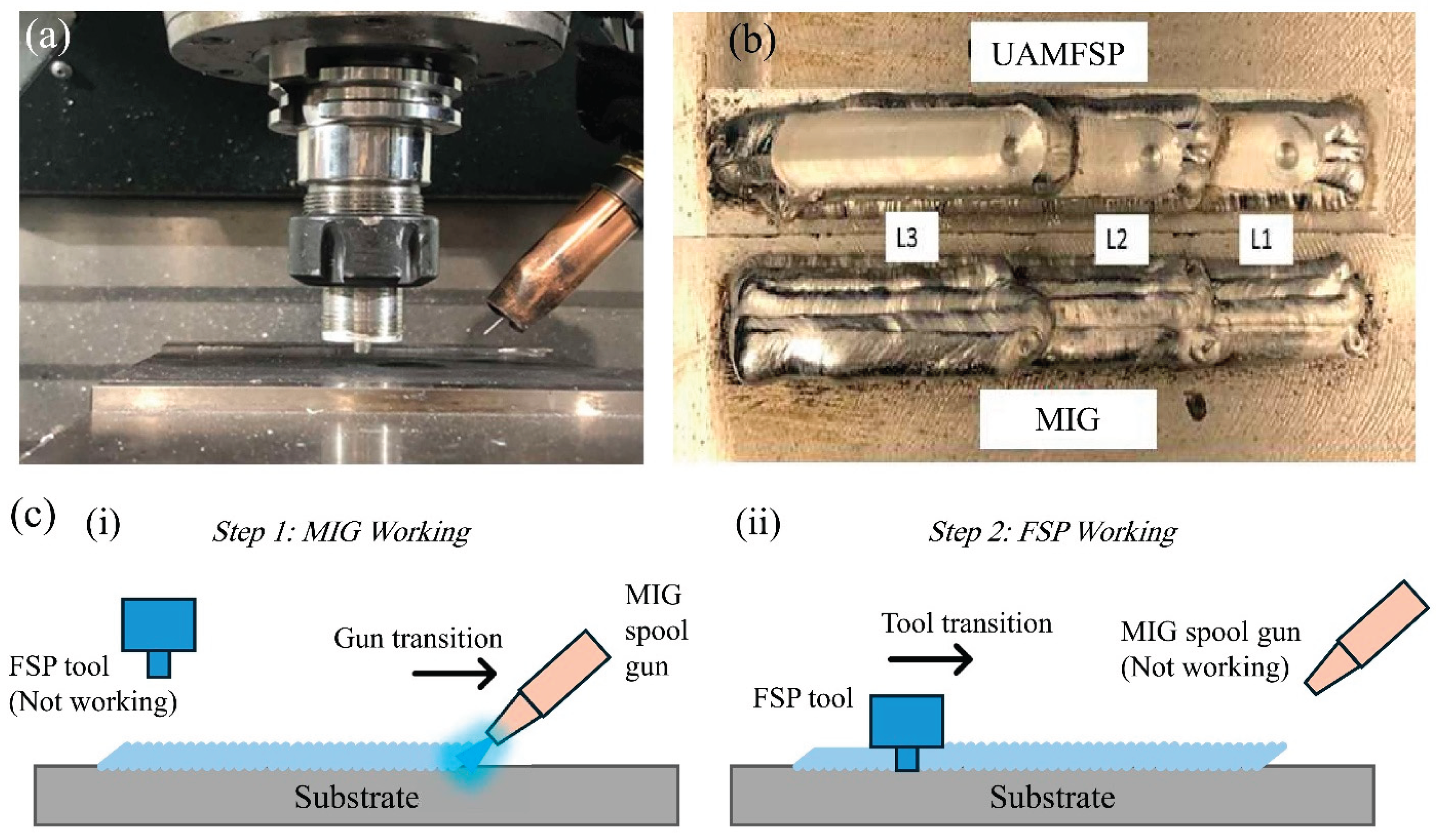
Figure 2.
(a) The locations on the specimen section in the walls, (b) a representative MIPAR-based microstructural analysis, and (c) IR thermal imaging camera location in the experimental setup.
Figure 2.
(a) The locations on the specimen section in the walls, (b) a representative MIPAR-based microstructural analysis, and (c) IR thermal imaging camera location in the experimental setup.
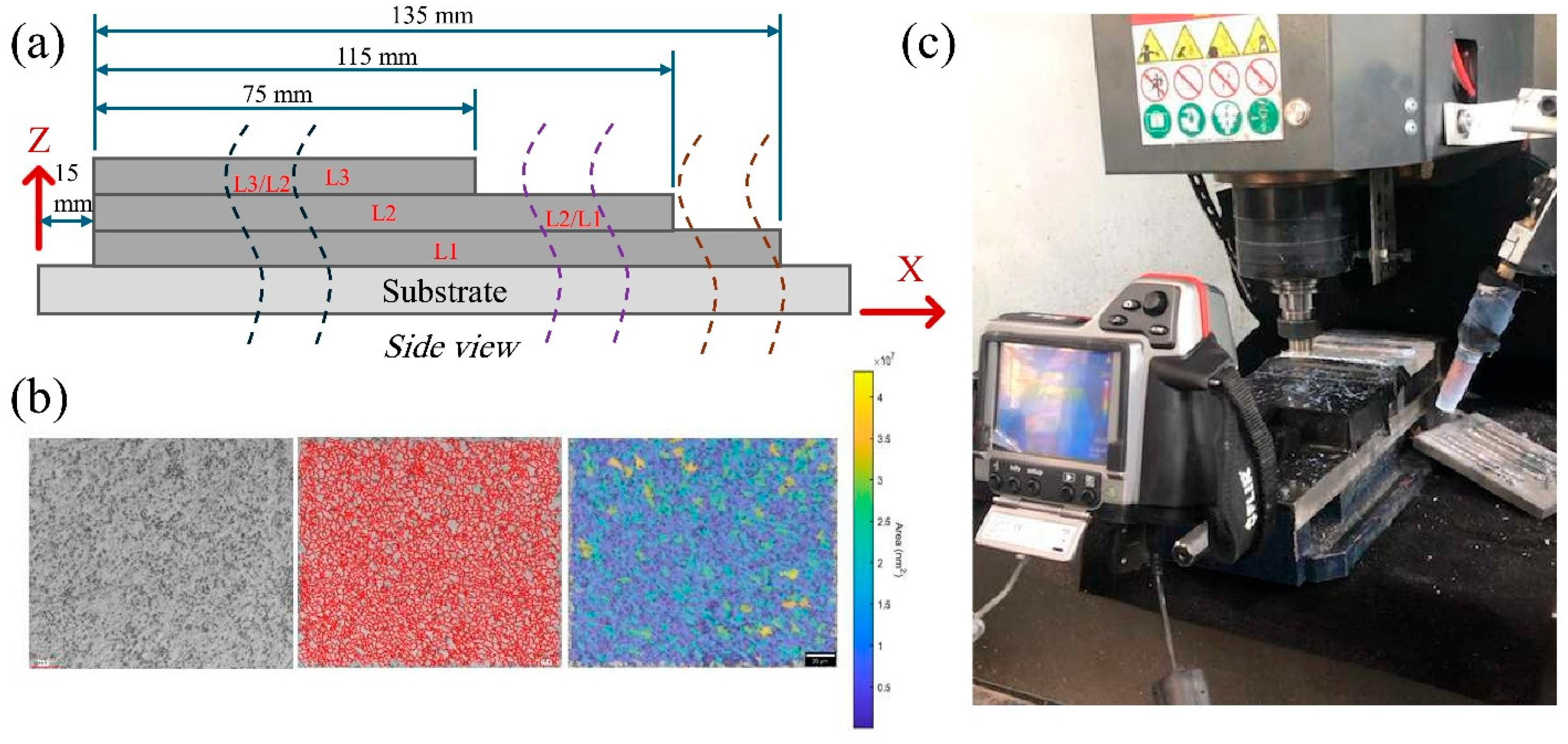
Figure 3.
Representative optical micrographs of the MIG-deposited and the UAMFSP-processed 4043 aluminum alloy walls, illustrating the evolution of grain morphology with build height. Sequential layers (L1, L2, and L3) denote the first, second, and third layers, respectively. The images of the UAMFSP fabricated sample highlight the influence of FSP on grain refinement and uniformity of the microstructure. Scale bar = 50 µm.
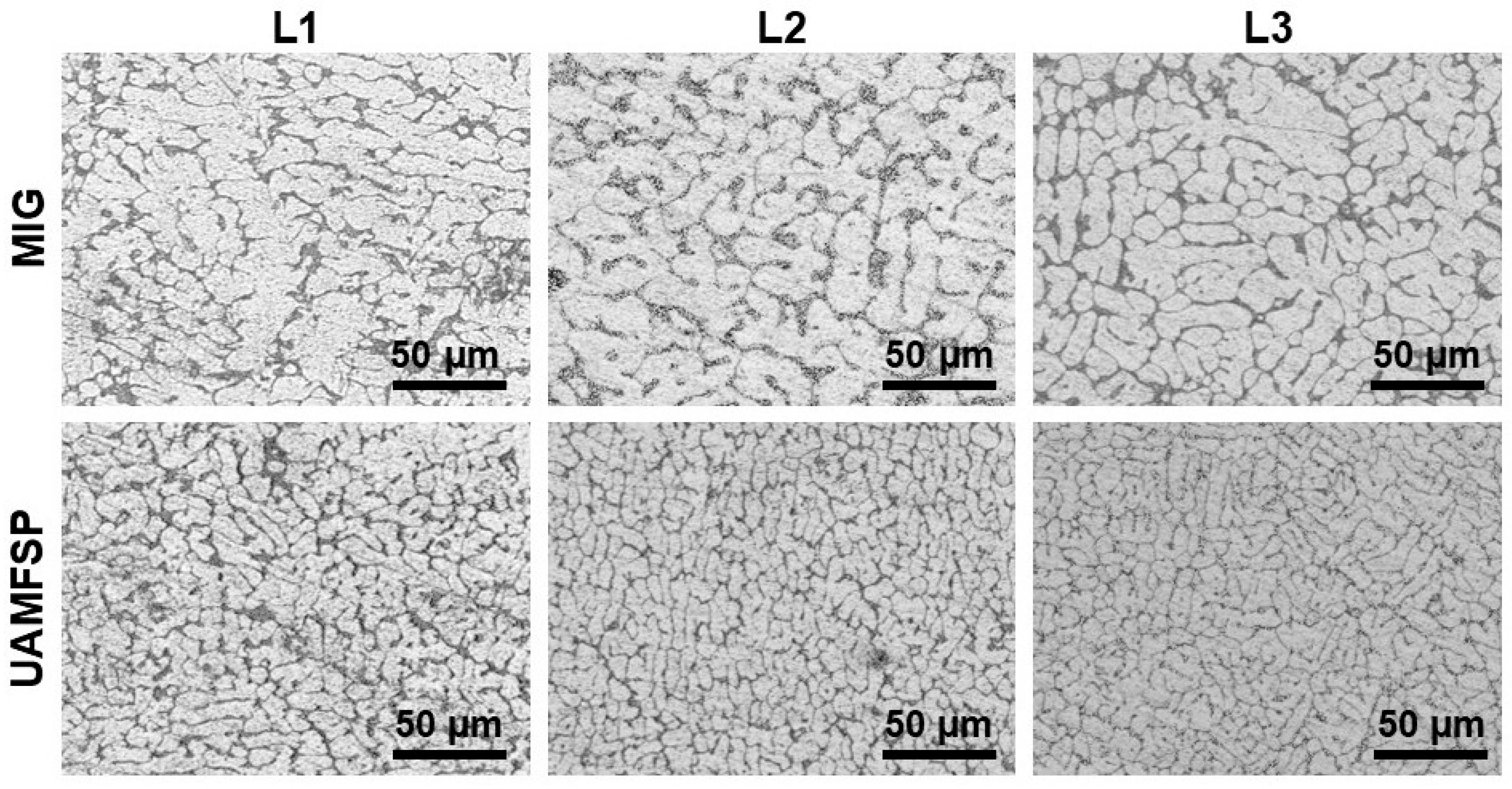
Figure 4.
The probability density distributions of the grain area, grain perimeter, grain equivalent diameter, and grain roundness for the MIG and the UAMFSP walls.
Figure 4.
The probability density distributions of the grain area, grain perimeter, grain equivalent diameter, and grain roundness for the MIG and the UAMFSP walls.
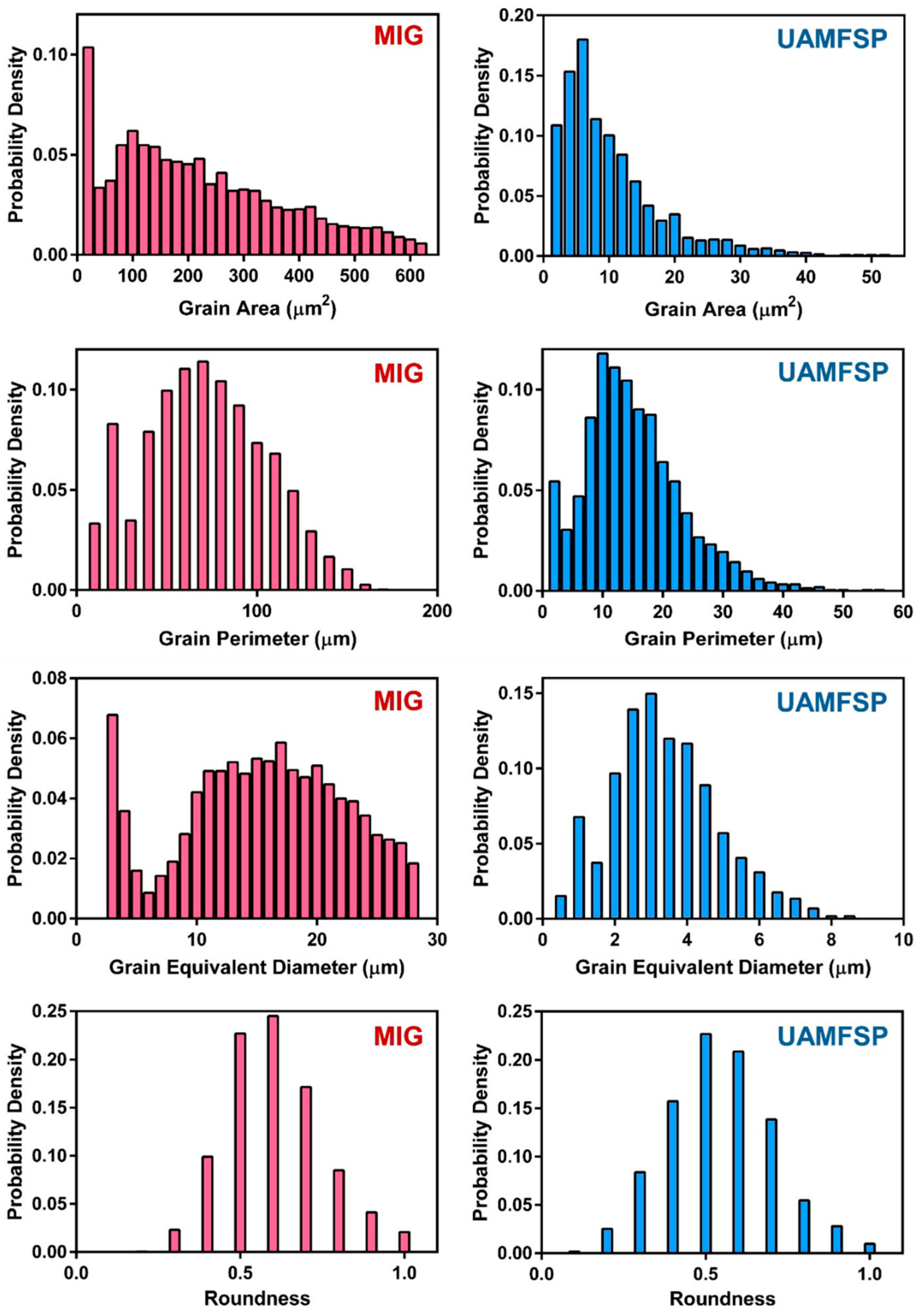
Figure 5.
The comparative probability density curves of the grain area, grain perimeter, grain equivalent diameter, and grain roundness for the MIG and the UAMFSP walls.
Figure 5.
The comparative probability density curves of the grain area, grain perimeter, grain equivalent diameter, and grain roundness for the MIG and the UAMFSP walls.
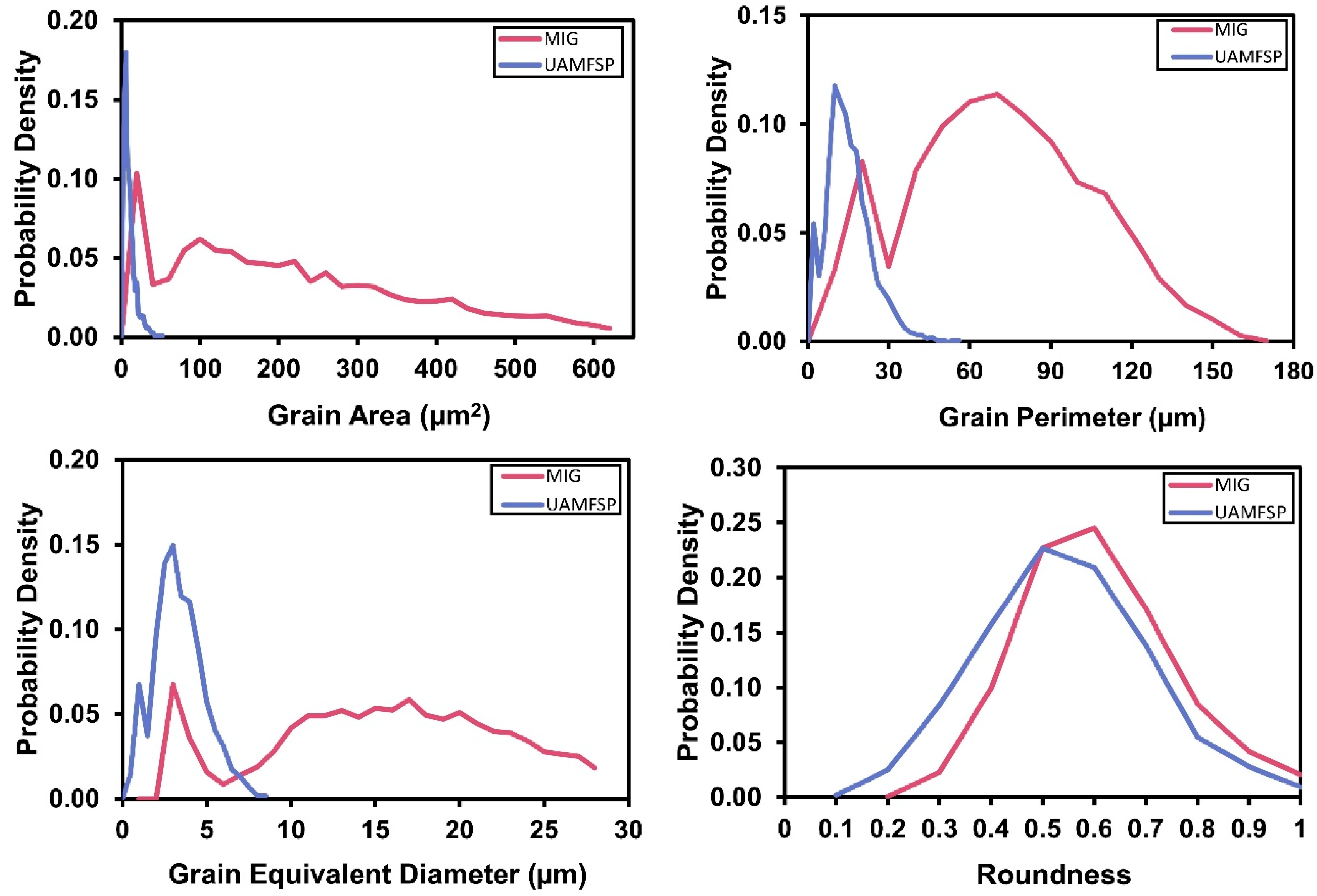
Figure 6.
The temperature contour maps (T(x,y), °C) obtained, utilizing the IR thermography, for the MIG and the UAMFSP walls across Layers 1 to 3, corresponding to L1 (60 s), L2 (50 s), and L3 (30 s). The temperature data were captured utilizing an FLIR T300 IR camera and processed in °C, with an emissivity of 0.95 on the aluminum surface. The color scale represents the distribution of the spatial temperature. Scale bar = 5 µm.
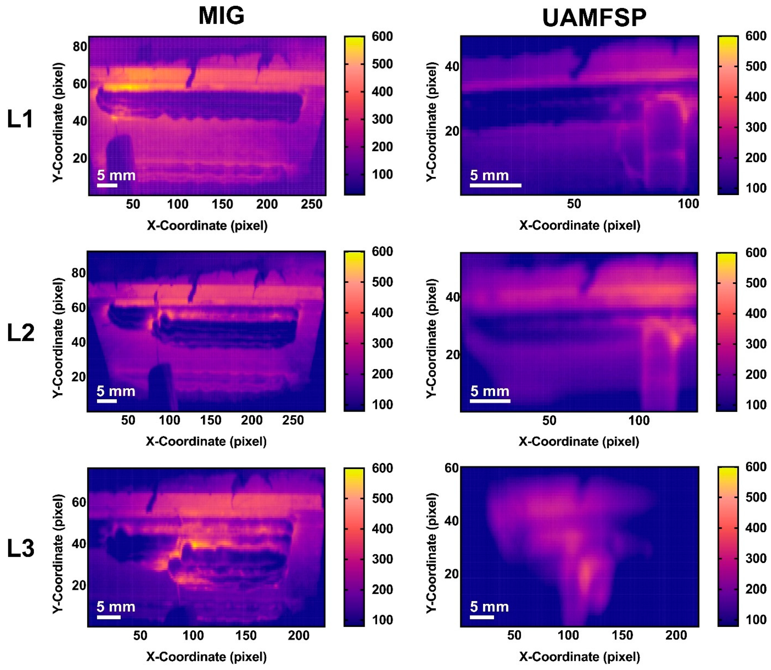
Figure 7.
Temporal variation of the maximum temperature (°C) throughout the entire deposition and processing sequence for Layers 1–3, along with comparative results between the MIG and UAMFSP walls across the corresponding layers. Temperature data were captured using a FLIR T300 IR camera and processed in °C, with an emissivity of 0.95 for the aluminum surface.
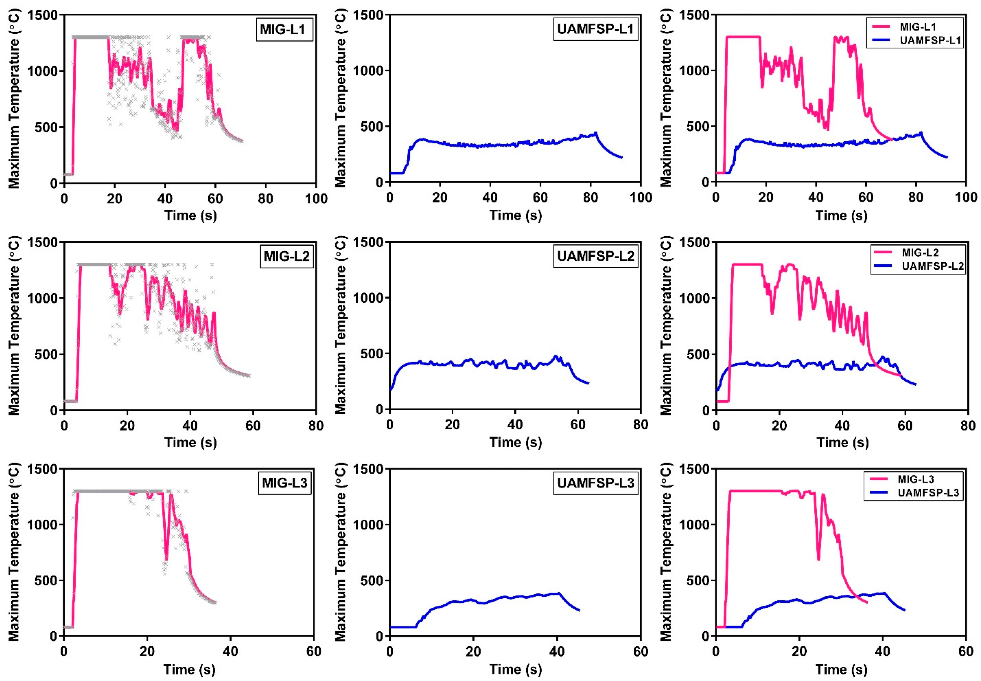
Figure 8.
The comparison of the maximum temperatures (mean ± SD) measured at Layers 1–3 for the MIG and UAMFSP walls. The UAMFSP process exhibited significantly lower temperature peaks across all layers (****p < 0.0001).
Figure 8.
The comparison of the maximum temperatures (mean ± SD) measured at Layers 1–3 for the MIG and UAMFSP walls. The UAMFSP process exhibited significantly lower temperature peaks across all layers (****p < 0.0001).
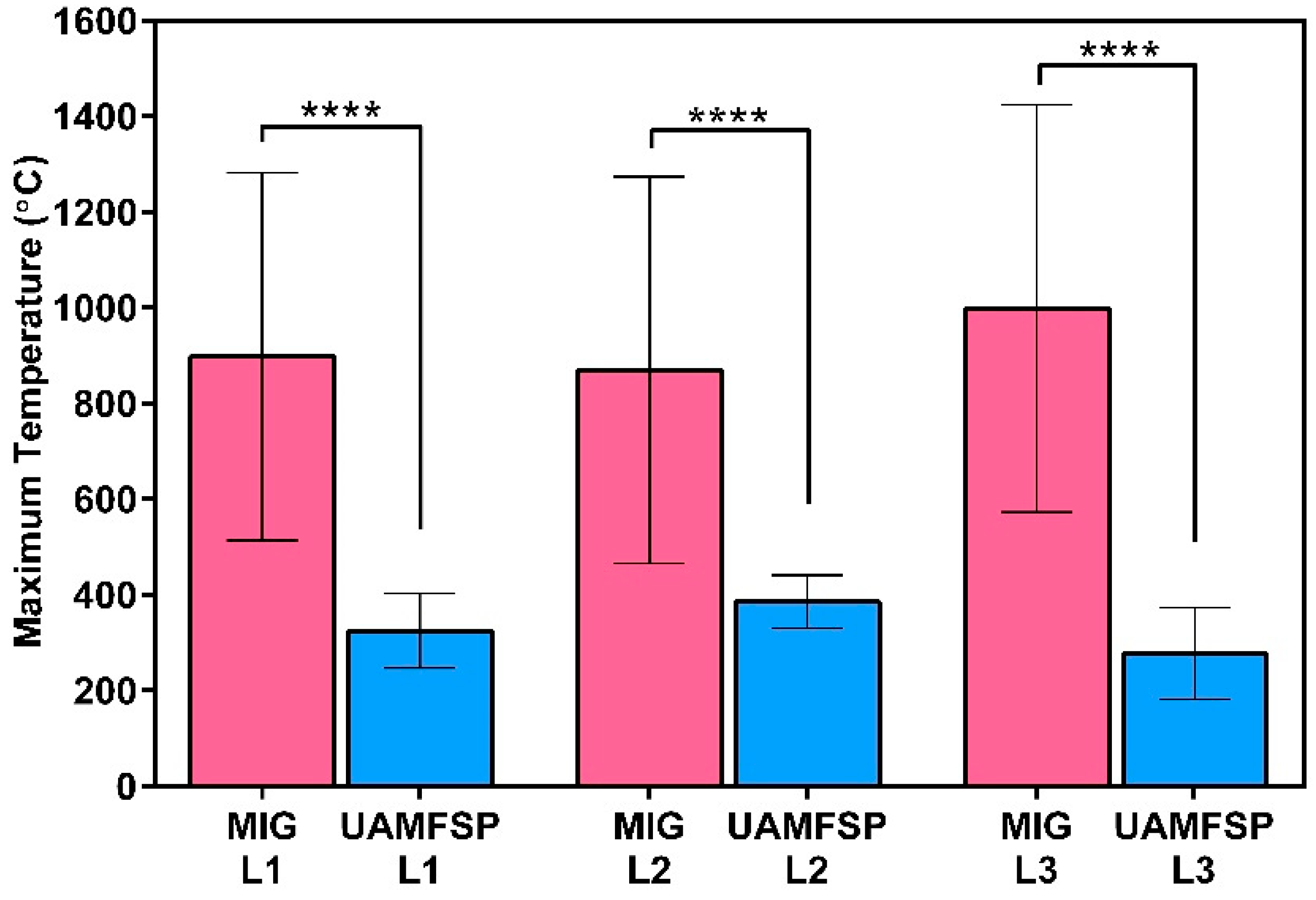
Figure 9.
The Vickers hardness (HV0.2) measurement results of the MIG and the UAMFSP fabricated samples. Error bars represent one standard deviation. The double asterisk (**) indicates a statistically significant difference (p = 0.0027).
Figure 9.
The Vickers hardness (HV0.2) measurement results of the MIG and the UAMFSP fabricated samples. Error bars represent one standard deviation. The double asterisk (**) indicates a statistically significant difference (p = 0.0027).
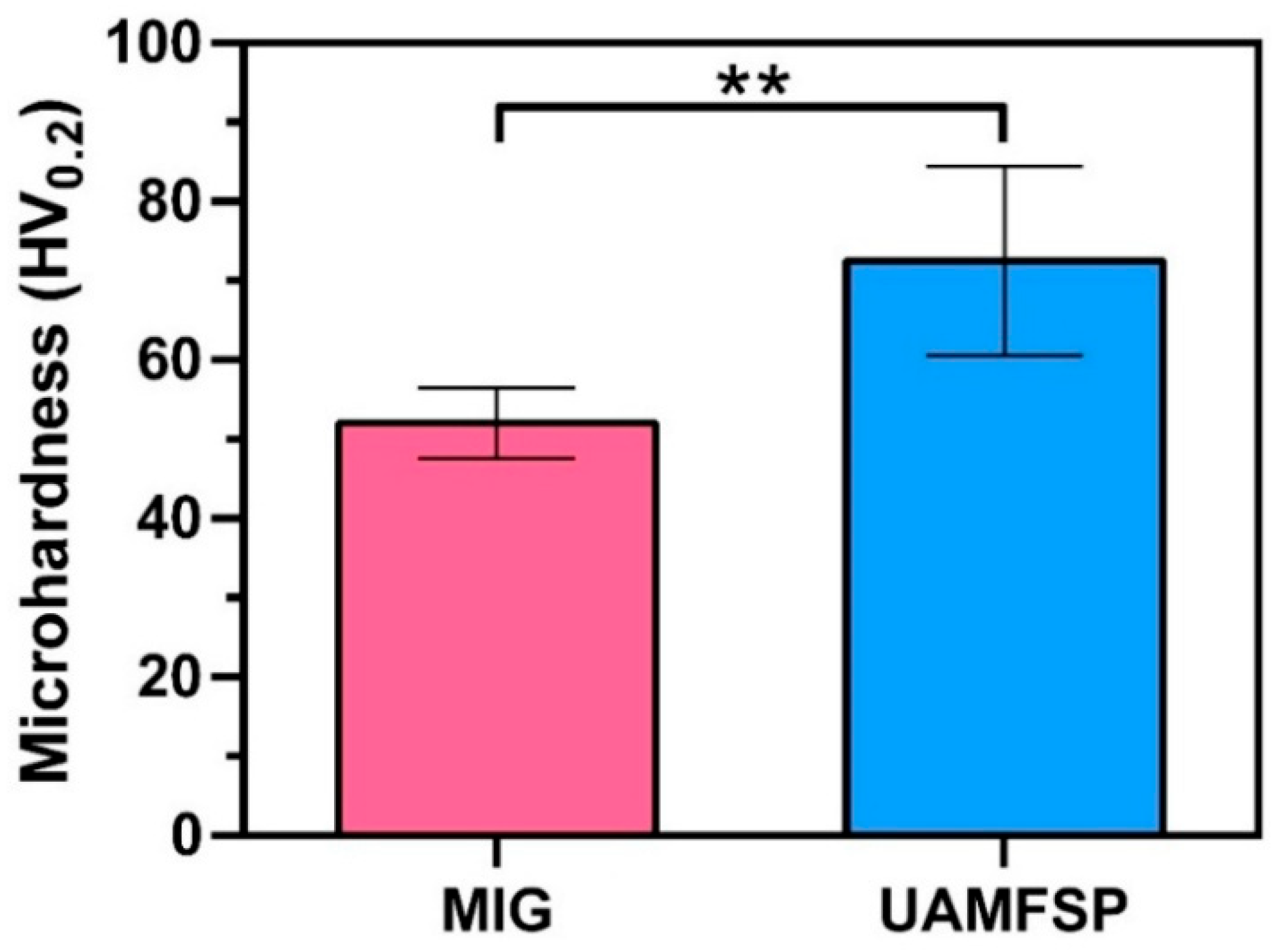
Figure 10.
Mechanism of grain refinement in UAMFSP via CDRX. The rotating FSP tool refined the MIG-deposited layer (bottom-right inset: dendritic grains) into fine equiaxed grains (top-left inset).
Figure 10.
Mechanism of grain refinement in UAMFSP via CDRX. The rotating FSP tool refined the MIG-deposited layer (bottom-right inset: dendritic grains) into fine equiaxed grains (top-left inset).
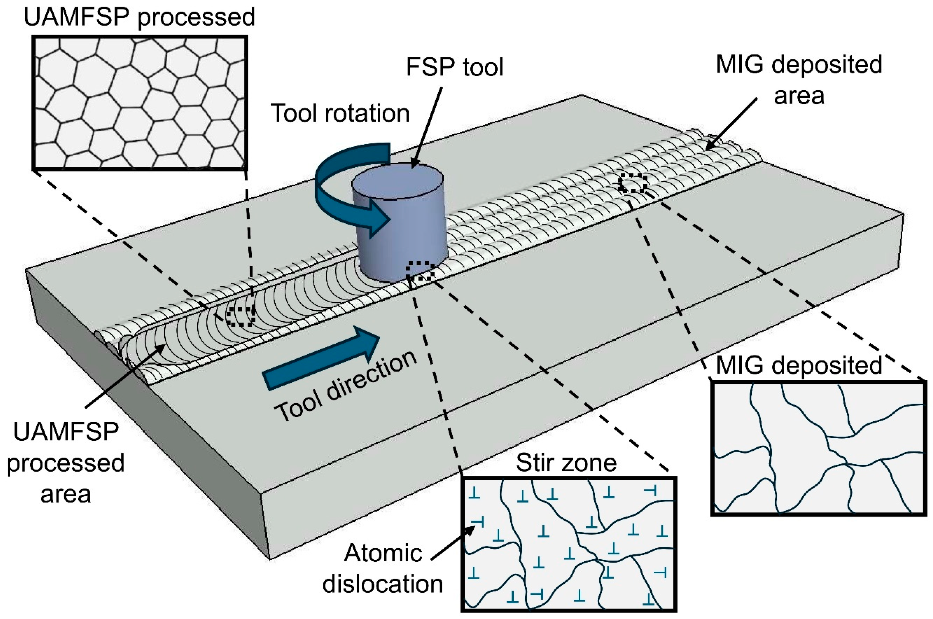
Figure 11.
The schematic illustration of the dislocation-mediated strengthening in the MIG and the UAMFSP walls. In the MIG condition, coarse, irregular grains permit long dislocation mean free paths (red arrows), enabling easy glide and a low hardness. In the UAMFSP condition, the SPD during FSP produced fine equiaxed grains, with a high boundary density, inducing dislocation pile-ups (blue arrows) at the grain boundaries and therefore significantly increasing the strength via Hall–Petch strengthening,.
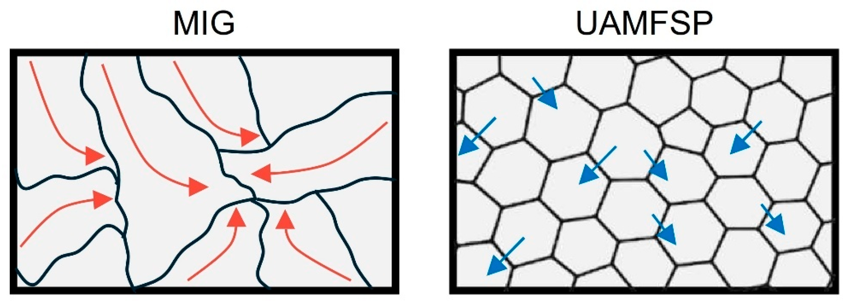

Table 1.
Nominal chemical compositions of the substrate (AA6061 aluminum alloy) and the filler (ER4043 aluminum wire) in wt.%.
Table 1.
Nominal chemical compositions of the substrate (AA6061 aluminum alloy) and the filler (ER4043 aluminum wire) in wt.%.
| Element | Mg | Fe | Mn | Cr | Si | Cu | Zn | Ti | Al |
|---|---|---|---|---|---|---|---|---|---|
| Substrate | 0.8-1.2 | ≤0.70 | ≤0.15 | 0.04-0.35 | 0.40-0.80 | 0.1-0.4 | ≤0.25 | ≤0.15 | Bal. |
| Filler (ER4043) | ≤0.05 | ≤0.8 | ≤0.05 | - | 4.5-6.0 | ≤0.3 | ≤0.1 | ≤0.2 | Bal. |
Table 2.
MIG parameters used for the fabrication of the two walls.
| Voltage (U) | Current (I) | Welding speed (v) (mm/min) | Wire stick-out (mm) | Argon flow rate (CHF) |
|---|---|---|---|---|
| 18 | 120 | 330 | 9 | 27 |
Table 3.
FSP parameters used in the fabrication of the UAMFSP wall.
| Layer | Tool rotational speed (vs) (RPM) | Tool travel speed (v) (mm/min) | Plunge depth (mm) |
|---|---|---|---|
| 1 | 600 | 50 | 0.2 |
| 2&3 | 1200 | 50 | 0.2 |
Table 4.
Grain size and morphology statistics of MIG and UAMFSP walls.
| Wall | Ā (µm²) | Ã (µm²) | σA | P̄ (µm) | P̃ | σP | D̄ | D̃ | σD | R̄ | R̃ | σR |
|---|---|---|---|---|---|---|---|---|---|---|---|---|
| MIG | 313.6 | 219.8 | 335.2 | 73.4 | 68 | 49.6 | 17.2 | 16.7 | 10.2 | 0.71 | 0.61 | 0.38 |
| UAMFSP | 10.9 | 6.4 | 13.1 | 14 | 12.1 | 9.5 | 3.2 | 2.9 | 1.9 | 0.62 | 0.57 | 0.29 |
Note: A=Grain Area; P=Grain Perimeter; Deq=Grain Equivalent Diameter; R=Grain Roundness. x̄=mean, x̃=median, and σx=standard deviation.
Table 5.
The average of maximum temperatures (°C) at Layers 1–3 for the MIG and UAMFSP walls.
| Process | L1 | L2 | L3 |
|---|---|---|---|
| MIG | 897.63 | 869.42 | 998.15 |
| UAMFSP | 324.45 | 386.21 | 277.23 |
Disclaimer/Publisher’s Note: The statements, opinions and data contained in all publications are solely those of the individual author(s) and contributor(s) and not of MDPI and/or the editor(s). MDPI and/or the editor(s) disclaim responsibility for any injury to people or property resulting from any ideas, methods, instructions or products referred to in the content. |
© 2025 by the authors. Licensee MDPI, Basel, Switzerland. This article is an open access article distributed under the terms and conditions of the Creative Commons Attribution (CC BY) license (http://creativecommons.org/licenses/by/4.0/).
Copyright: This open access article is published under a Creative Commons CC BY 4.0 license, which permit the free download, distribution, and reuse, provided that the author and preprint are cited in any reuse.


